log splitter...when loading a ram-type log splitter, place your hands on the sides of the log not at...
TRANSCRIPT

Log Splitter
04581300 2/13Printed in USA
ENGLISH
FRANÇAIS
Owner/Operator ManualManuel Du Propriétaire/Utilisateur
E10The use of any gasoline exceeding 10% ethanol (E10) or 10% MTBE will void the product warranty.L’utilisation d’une essence contenant plus de 10% d’éthanol (E10) ou de 10% de MTBE annulent la garantie.
Models917011 – 22-Ton Log Splitter
(SN 000101 +)
917012 – 25-Ton Log Splitter(SN 000101 +)
SAFETY. . . . . . . . . . . . . . . . . . . . . . . . . . 4
CONTROLS AND FEATURES . . . . . . . 10
OPERATION . . . . . . . . . . . . . . . . . . . . . 11
MAINTENANCE SCHEDULE . . . . . . . . 18
STORAGE . . . . . . . . . . . . . . . . . . . . . . . 20
TROUBLESHOOTING . . . . . . . . . . . . . 21
SERVICE PARTS . . . . . . . . . . . . . . . . . 22
SPECIFICATIONS. . . . . . . . . . . . . . . . . 22
ACCESSORIES. . . . . . . . . . . . . . . . . . . 22
WARRANTY . . . . . . . . . . . . . . . . . . . . . 23
Manuales en idiomas diferentes del ingles
Puede obtener manuales en idiomas diferentes del inglés en su distribuidor. Visite a su distribuidor o vaya a www.ariens.com para obtener una lista de idiomas disponibles para su equipo.También puede imprimir manuales en idiomas diferentes del inglés descargándolos gratuitamente de nuestra página Web:
http://www.ariens.com
THE MANUALBefore operation of unit, carefully and completely read your manual. The contents will provide you with an understanding of safety instructions and controls during normal operation and maintenance.
ENGINE MANUALThe engine on this unit is covered by aseparate manual specific to the engine. Thismanual is included in the literature packagethat shipped with the unit. Refer to thismanual for engine service recommendations.If the engine manual is not available, contactthe engine manufacturer for a replacementmanual.
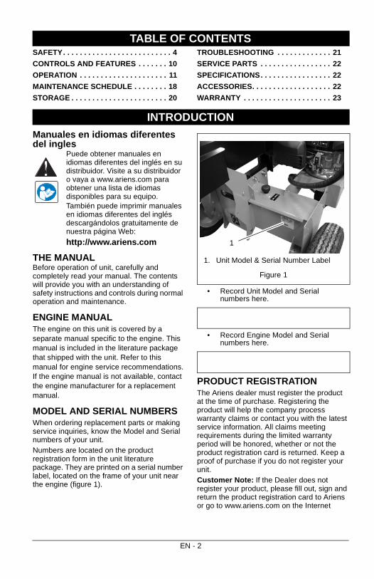
MODEL AND SERIAL NUMBERSWhen ordering replacement parts or making service inquiries, know the Model and Serial numbers of your unit.Numbers are located on the product registration form in the unit literature package. They are printed on a serial number label, located on the frame of your unit near the engine (figure 1).
• Record Unit Model and Serial numbers here.
• Record Engine Model and Serial numbers here.
PRODUCT REGISTRATIONThe Ariens dealer must register the product at the time of purchase. Registering the product will help the company process warranty claims or contact you with the latest service information. All claims meeting requirements during the limited warranty period will be honored, whether or not the product registration card is returned. Keep a proof of purchase if you do not register your unit.Customer Note: If the Dealer does not register your product, please fill out, sign and return the product registration card to Ariens or go to www.ariens.com on the Internet
TABLE OF CONTENTS
INTRODUCTION
Figure 1
1. Unit Model & Serial Number Label
1
EN - 2
UNAUTHORIZED REPLACEMENT PARTSUse only Ariens replacement parts. The replacement of any part on this unit with anything other than an Ariens authorized replacement part may adversely affect the performance, durability, and safety of this unit and may void the warranty. Ariens disclaims liability for any claims or damages, whether warranty, property damage, personal injury or death arising out of the use of unauthorized replacement parts. NOTE: A complete Parts manual may be downloaded from www.ariens.com on the Internet
DELIVERYCustomer Note: If you have purchased this product without complete assembly and instruction by your retailer, it is your responsibility to:
• Read and understand all assembly instructions in this manual. If you do not understand or have difficulty following the instructions, contact your nearest Ariens Dealer for assistance.
NOTE: To locate your nearest Ariens Dealer, go to www.ariens.com on the Internet.
Before Attempting to Operate Your Unit:
1. Make sure all assembly has been properly completed.
2. Understand all Safety Precautions provided in the manuals.
3. Review control functions and operation of the unit. Do not operate the unit unless all controls function as described in this manual.
4. Review recommended lubrication, maintenance and adjustments.
5. Review Limited Warranty Policy.6. Fill out a product registration card and
return the card to the Ariens Company or go to www.ariens.com.
DISCLAIMER Ariens reserves the right to discontinue, change, and improve its products at any time without notice or obligation to the purchaser.
The descriptions and specifications contained in this manual were in effect at printing. Equipment described within this manual may be optional. Some illustrations may not be applicable to your unit.
WARNING: Improper assembly or adjustments can cause serious injury.
EN - 3
Read these safety rules and follow them closely. Failure to follow these rules could lead to loss of control of unit, severe personal injury or death to you or bystanders or result in damage to property or the machine.
Safety Alert Symbol
SIGNAL WORDSThe safety alert symbols above and signal words below are used on decals and in this manual.Read and understand all safety messages.
1. Danger
2. Warning
3. Caution
4. NoticeNOTICE: Indicates information or procedures that are considered important but not hazard related. If not avoided property damage could result.
5. ImportantIMPORTANT: Indicates general reference information worthy of special attention.
SAFETY DECALSThis splitting machine is capable of crushing or amputating body parts. Failure to observe the following safety instructions could result in serious injury or death.The safety decals on your machine are visual reminders of the important safety information found in this manual. All messages found on your unit must be fully understood and carefully followed. Safety decals found on the machine are explained below.Always replace missing or damaged safety decals. Replacement decals can be found in the parts manual for your machine and ordered from your dealer.
Refer to Figure 2 for Safety Decal locations.
SAFETY
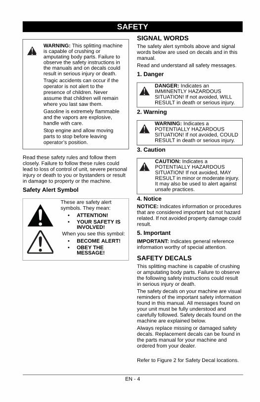
WARNING: This splitting machine is capable of crushing or amputating body parts. Failure to observe the safety instructions in the manuals and on decals could result in serious injury or death.Tragic accidents can occur if the operator is not alert to the presence of children. Never assume that children will remain where you last saw them.Gasoline is extremely flammable and the vapors are explosive, handle with care.Stop engine and allow moving parts to stop before leaving operator’s position.
These are safety alert symbols. They mean:
• ATTENTION! • YOUR SAFETY IS
INVOLVED! When you see this symbol:
• BECOME ALERT! • OBEY THE
MESSAGE!
DANGER: Indicates an IMMINENTLY HAZARDOUS SITUATION! If not avoided, WILL RESULT in death or serious injury.
WARNING: Indicates a POTENTIALLY HAZARDOUS SITUATION! If not avoided, COULD RESULT in death or serious injury.
CAUTION: Indicates a POTENTIALLY HAZARDOUS SITUATION! If not avoided, MAY RESULT in minor or moderate injury. It may also be used to alert against unsafe practices.
EN - 4
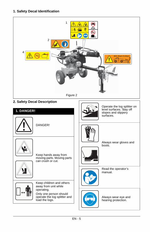
1. Safety Decal Identification
2. Safety Decal Description
08000722
08000723
08000724
08000725
MAX. 45mph (72.42kph)
Figure 2
1
2
3
4
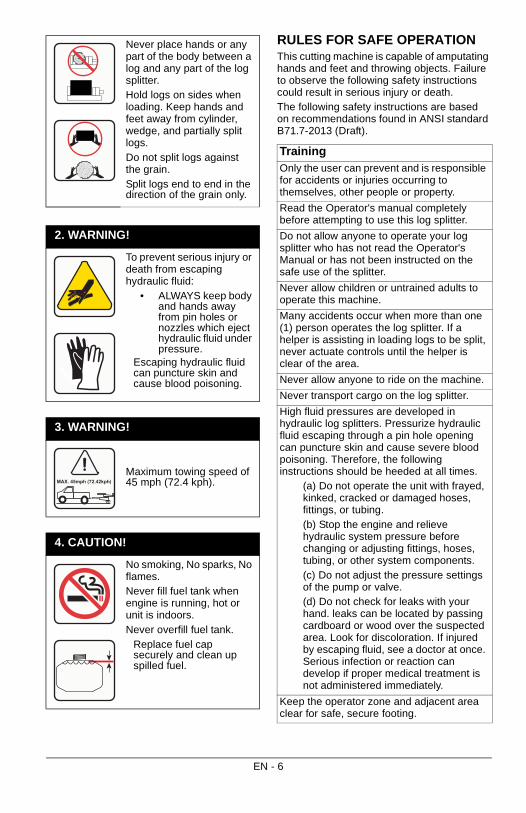
1. DANGER!
DANGER!
Keep hands away from moving parts. Moving parts can crush or cut.
Keep children and others away from unit while operating.Only one person should operate the log splitter and load the logs.
Operate the log splitter on level surfaces. Stay off slopes and slippery surfaces.
Always wear gloves and boots.
Read the operator’s manual.
Always wear eye and hearing protection.
EN - 5
RULES FOR SAFE OPERATIONThis cutting machine is capable of amputating hands and feet and throwing objects. Failure to observe the following safety instructions could result in serious injury or death.The following safety instructions are based on recommendations found in ANSI standard B71.7-2013 (Draft).
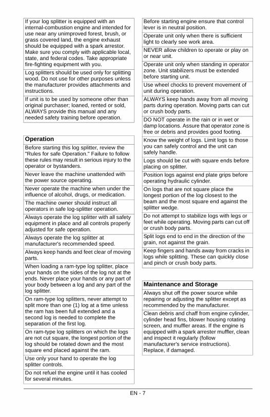
Never place hands or any part of the body between a log and any part of the log splitter.Hold logs on sides when loading. Keep hands and feet away from cylinder, wedge, and partially split logs.Do not split logs against the grain.Split logs end to end in the direction of the grain only.
2. WARNING!
To prevent serious injury or death from escaping hydraulic fluid:
• ALWAYS keep body and hands away from pin holes or nozzles which eject hydraulic fluid under pressure.
Escaping hydraulic fluid can puncture skin and cause blood poisoning.
3. WARNING!
Maximum towing speed of 45 mph (72.4 kph).
4. CAUTION!
No smoking, No sparks, No flames.Never fill fuel tank when engine is running, hot or unit is indoors.Never overfill fuel tank.
Replace fuel cap securely and clean up spilled fuel.
MAX. 45mph (72.42kph)
TrainingOnly the user can prevent and is responsible for accidents or injuries occurring to themselves, other people or property.
Read the Operator's manual completely before attempting to use this log splitter.
Do not allow anyone to operate your log splitter who has not read the Operator's Manual or has not been instructed on the safe use of the splitter.
Never allow children or untrained adults to operate this machine.
Many accidents occur when more than one (1) person operates the log splitter. If a helper is assisting in loading logs to be split, never actuate controls until the helper is clear of the area.
Never allow anyone to ride on the machine.
Never transport cargo on the log splitter.
High fluid pressures are developed in hydraulic log splitters. Pressurize hydraulic fluid escaping through a pin hole opening can puncture skin and cause severe blood poisoning. Therefore, the following instructions should be heeded at all times.
(a) Do not operate the unit with frayed, kinked, cracked or damaged hoses, fittings, or tubing.(b) Stop the engine and relieve hydraulic system pressure before changing or adjusting fittings, hoses, tubing, or other system components.(c) Do not adjust the pressure settings of the pump or valve.(d) Do not check for leaks with your hand. leaks can be located by passing cardboard or wood over the suspected area. Look for discoloration. If injured by escaping fluid, see a doctor at once. Serious infection or reaction can develop if proper medical treatment is not administered immediately.
Keep the operator zone and adjacent area clear for safe, secure footing.
EN - 6
If your log splitter is equipped with an internal-combustion engine and intended for use near any unimproved forest, brush, or grass covered land, the engine exhaust should be equipped with a spark arrestor. Make sure you comply with applicable local, state, and federal codes. Take appropriate fire-fighting equipment with you.
Log splitters should be used only for splitting wood. Do not use for other purposes unless the manufacturer provides attachments and instructions.
If unit is to be used by someone other than original purchaser; loaned, rented or sold, ALWAYS provide this manual and any needed safety training before operation.
OperationBefore starting this log splitter, review the "Rules for safe Operation." Failure to follow these rules may result in serious injury to the operator or bystanders.
Never leave the machine unattended with the power source operating.
Never operate the machine when under the influence of alcohol, drugs, or medication.
The machine owner should instruct all operators in safe log-splitter operation.
Always operate the log splitter with all safety equipment in place and all controls properly adjusted for safe operation.
Always operate the log splitter at manufacturer's recommended speed.
Always keep hands and feet clear of moving parts.
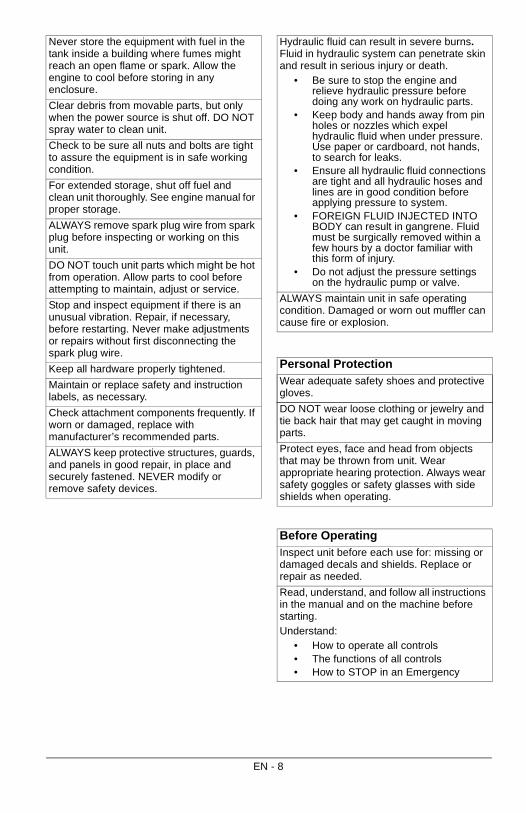
When loading a ram-type log splitter, place your hands on the sides of the log not at the ends. Never place your hands or any part of your body between a log and any part of the log splitter.
On ram-type log splitters, never attempt to split more than one (1) log at a time unless the ram has been full extended and a second log is needed to complete the separation of the first log.
On ram-type log splitters on which the logs are not cut square, the longest portion of the log should be rotated down and the most square end placed against the ram.
Use only your hand to operate the log splitter controls.
Do not refuel the engine until it has cooled for several minutes.
Before starting engine ensure that control lever is in neutral position.
Operate unit only when there is sufficient light to clearly see work area.
NEVER allow children to operate or play on or near unit.
Operate unit only when standing in operator zone. Unit stabilizers must be extended before starting unit.
Use wheel chocks to prevent movement of unit during operation.
ALWAYS keep hands away from all moving parts during operation. Moving parts can cut or crush body parts.
DO NOT operate in the rain or in wet or damp locations. Assure that operator zone is free or debris and provides good footing.
Know the weight of logs. Limit logs to those you can safely control and the unit can safely handle.
Logs should be cut with square ends before placing on splitter.
Position logs against end plate grips before operating hydraulic cylinder.
On logs that are not square place the longest portion of the log closest to the beam and the most square end against the splitter wedge.
Do not attempt to stabilize logs with legs or feet while operating. Moving parts can cut off or crush body parts.
Split logs end to end in the direction of the grain, not against the grain.
Keep fingers and hands away from cracks in logs while splitting. These can quickly close and pinch or crush body parts.
Maintenance and StorageAlways shut off the power source while repairing or adjusting the splitter except as recommended by the manufacturer.
Clean debris and chaff from engine cylinder, cylinder head fins, blower housing rotating screen, and muffler areas. If the engine is equipped with a spark arrester muffler, clean and inspect it regularly (follow manufacturer's service instructions). Replace, if damaged.
EN - 7
Never store the equipment with fuel in the tank inside a building where fumes might reach an open flame or spark. Allow the engine to cool before storing in any enclosure.
Clear debris from movable parts, but only when the power source is shut off. DO NOT spray water to clean unit.
Check to be sure all nuts and bolts are tight to assure the equipment is in safe working condition.
For extended storage, shut off fuel and clean unit thoroughly. See engine manual for proper storage.
ALWAYS remove spark plug wire from spark plug before inspecting or working on this unit.
DO NOT touch unit parts which might be hot from operation. Allow parts to cool before attempting to maintain, adjust or service.
Stop and inspect equipment if there is an unusual vibration. Repair, if necessary, before restarting. Never make adjustments or repairs without first disconnecting the spark plug wire.
Keep all hardware properly tightened.
Maintain or replace safety and instruction labels, as necessary.
Check attachment components frequently. If worn or damaged, replace with manufacturer’s recommended parts.
ALWAYS keep protective structures, guards, and panels in good repair, in place and securely fastened. NEVER modify or remove safety devices.
Hydraulic fluid can result in severe burns. Fluid in hydraulic system can penetrate skin and result in serious injury or death.
• Be sure to stop the engine and relieve hydraulic pressure before doing any work on hydraulic parts.
• Keep body and hands away from pin holes or nozzles which expel hydraulic fluid when under pressure. Use paper or cardboard, not hands, to search for leaks.
• Ensure all hydraulic fluid connections are tight and all hydraulic hoses and lines are in good condition before applying pressure to system.
• FOREIGN FLUID INJECTED INTO BODY can result in gangrene. Fluid must be surgically removed within a few hours by a doctor familiar with this form of injury.
• Do not adjust the pressure settings on the hydraulic pump or valve.
ALWAYS maintain unit in safe operating condition. Damaged or worn out muffler can cause fire or explosion.
Personal ProtectionWear adequate safety shoes and protective gloves.
DO NOT wear loose clothing or jewelry and tie back hair that may get caught in moving parts.
Protect eyes, face and head from objects that may be thrown from unit. Wear appropriate hearing protection. Always wear safety goggles or safety glasses with side shields when operating.
Before OperatingInspect unit before each use for: missing or damaged decals and shields. Replace or repair as needed.
Read, understand, and follow all instructions in the manual and on the machine before starting.Understand:
• How to operate all controls• The functions of all controls• How to STOP in an Emergency
EN - 8
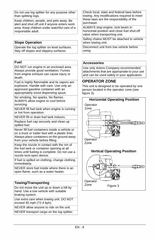
OPERATOR ZONEThis unit is designed to be operated by one person located in the operator zone (see figure 3).
Do not use log splitter for any purpose other than splitting logs.
Keep children, people, and pets away. Be alert and shut off unit if anyone enters work area. Keep children under watchful care of a responsible adult.
Slope OperationOperate the log splitter on level surfaces. Stay off slopes and slippery surfaces.
FuelDO NOT run engine in an enclosed area. Always provide good ventilation. Fumes from engine exhaust can cause injury or death.
Fuel is highly flammable and its vapors are explosive. Handle with care. Use only an approved gasoline container with an appropriately sized dispensing spout.
No smoking, No sparks, No flames. ALWAYS allow engine to cool before servicing.
NEVER fill fuel tank when engine is running or hot from operation.
NEVER fill or drain fuel tank indoors.
Replace fuel cap securely and clean up spilled fuel.
Never fill fuel containers inside a vehicle or on a truck or trailer bed with a plastic liner. Always place containers on the ground away from your vehicle before filling.
Keep the nozzle in contact with the rim of the fuel tank or container opening at all times until fueling is complete. Do not use a nozzle lock-open device.
If fuel is spilled on clothing, change clothing immediately.
NEVER store fuel inside where there is an open flame, such as a water heater.
Towing/TransportingDo not move the unit up or down a hill by hand. Use a tow vehicle with suitable braking system.
Use extra care when towing unit. DO NOT exceed 45 mph (72.4 kph).
NEVER allow anyone to ride on the unit.
NEVER transport cargo on the log splitter.
Check local, state and federal laws before towing. Any modifications required to meet these laws are the responsibility of the purchaser.
ALWAYS stop engine, lock beam in horizontal position and close fuel shut-off valve when transporting unit.
Safety chains MUST be attached to vehicle when towing unit.
Disconnect unit from tow vehicle before using.
AccessoriesUse only Ariens Company-recommended attachments that are appropriate to your use and can be used safely in your application.
Horizontal Operating Position
Vertical Operating Position
Operator Zone
Operator Zone
Operator Zone
Figure 3
EN - 9
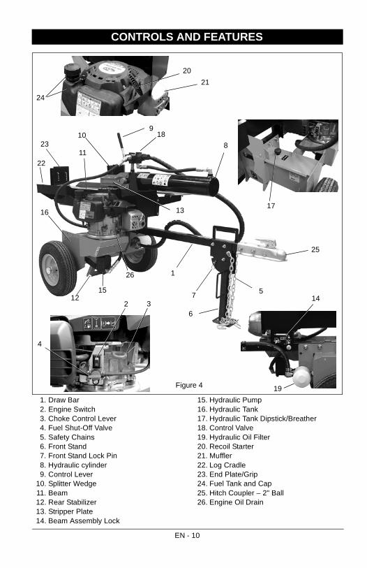
1. Draw Bar2. Engine Switch3. Choke Control Lever4. Fuel Shut-Off Valve5. Safety Chains6. Front Stand7. Front Stand Lock Pin8. Hydraulic cylinder9. Control Lever
10. Splitter Wedge11. Beam12. Rear Stabilizer13. Stripper Plate14. Beam Assembly Lock
15. Hydraulic Pump16. Hydraulic Tank17. Hydraulic Tank Dipstick/Breather18. Control Valve19. Hydraulic Oil Filter20. Recoil Starter21. Muffler22. Log Cradle23. End Plate/Grip24. Fuel Tank and Cap25. Hitch Coupler – 2" Ball26. Engine Oil Drain
CONTROLS AND FEATURES
Figure 4
2
1
36
910
13
11
57
15
19
14
17
18
16
23
4
20
21
22
8
24
25
26
12
EN - 10
CONTROLS AND FEATURES
See figure 4 for all controls and features locations.
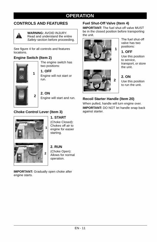
Engine Switch (Item 2)The engine switch has two positions:
1. OFFEngine will not start or run.
2. ONEngine will start and run.
Choke Control Lever (Item 3)
1. START(Choke Closed): Chokes off air to engine for easier starting.
2. RUN(Choke Open): Allows for normal operation.
IMPORTANT: Gradually open choke after engine starts.
Fuel Shut-Off Valve (Item 4)IMPORTANT: The fuel shut-off valve MUST be in the closed position before transporting the unit.
The fuel shut-off valve has two positions:
1. OFFUse this position to service, transport, or store the unit.
2. ONUse this position to run the unit.
Recoil Starter Handle (Item 20)When pulled, handle will turn engine over.IMPORTANT: DO NOT let handle snap back against starter.
OPERATION
WARNING: AVOID INJURY. Read and understand the entire Safety section before proceeding.
1
2
2
1
1
2
EN - 11
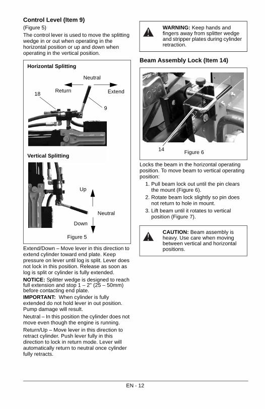
Control Level (Item 9)(Figure 5)The control lever is used to move the splitting wedge in or out when operating in the horizontal position or up and down when operating in the vertical position.
Extend/Down – Move lever in this direction to extend cylinder toward end plate. Keep pressure on lever until log is split. Lever does not lock in this position. Release as soon as log is split or cylinder is fully extended.NOTICE: Splitter wedge is designed to reach full extension and stop 1 – 2" (25 – 50mm) before contacting end plate.IMPORTANT: When cylinder is fully extended do not hold lever in out position. Pump damage will result. Neutral – In this position the cylinder does not move even though the engine is running.Return/Up – Move lever in this direction to retract cylinder. Push lever fully in this direction to lock in return mode. Lever will automatically return to neutral once cylinder fully retracts.
Beam Assembly Lock (Item 14)
Locks the beam in the horizontal operating position. To move beam to vertical operating position:
1. Pull beam lock out until the pin clears the mount (Figure 6).
2. Rotate beam lock slightly so pin does not return to hole in mount.
3. Lift beam until it rotates to vertical position (Figure 7).
Figure 5
Horizontal Splitting
Vertical Splitting
Return Extend
Neutral
Up
Down
Neutral
9
18
WARNING: Keep hands and fingers away from splitter wedge and stripper plates during cylinder retraction.
CAUTION: Beam assembly is heavy. Use care when moving between vertical and horizontal positions.
Figure 614
EN - 12
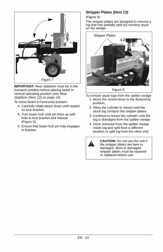
IMPORTANT: Rear stabilizer must be in the transport position before placing beam in vertical operating position (see Rear Stabilizer (Item 12) on page 14).To move beam to horizontal position:
4. Carefully rotate beam down until seated on lock bracket.
5. Turn beam lock until pin lines up with hole in lock bracket and release (Figure 6).
6. Ensure that beam lock pin fully engages in bracket.
Stripper Plates (Item 13)(Figure 8)The stripper plates are designed to remove a log that has partially split but remains stuck on the wedge.
To remove stuck logs from the splitter wedge:1. Move the control lever to the Return/Up
position.2. Allow the cylinder to retract until the
stuck log contacts the stripper plates. 3. Continue to retract the cylinder until the
log is dislodged from the splitter wedge.4. Once removed from the splitter wedge
rotate log and split from a different location or split log from the other end.
Figure 7
CAUTION: Do not use the unit if the stripper plates are bent or damaged. Bent or damaged stripper plates must be repaired or replaced before use.
Figure 8
Stripper Plates
EN - 13
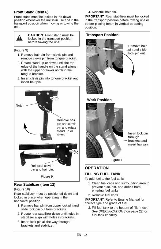
Front Stand (Item 6)Front stand must be locked in the down position whenever the unit is in use and in the transport position when moving or towing the unit.
(Figure 9)1. Remove hair pin from clevis pin and
remove clevis pin from tongue bracket.2. Rotate stand up or down until the top
edge of the handle on the stand aligns with the upper or lower notch in the tongue bracket.
3. Insert clevis pin into tongue bracket and insert hair pin.
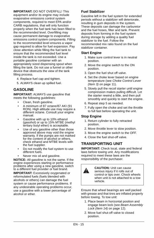
Rear Stabilizer (Item 12)(Figure 10)Rear stabilizer must be positioned down and locked in place when operating in the horizontal position.
1. Remove hair pin from upper lock pin and slide lock pin out from brackets.
2. Rotate rear stabilizer down until holes in stabilizer align with holes in brackets.
3. Insert lock pin all the way through brackets and stabilizer.
4. Reinstall hair pin.IMPORTANT: Rear stabilizer must be locked in the transport position before towing unit or before placing beam in vertical operating position.
OPERATION
FILLING FUEL TANKTo add fuel to the fuel tank:
1. Clean fuel caps and surrounding area to prevent dust, dirt, and debris from entering fuel tanks.
2. Remove fuel caps.IMPORTANT: Refer to Engine Manual for correct type and grade of fuel.
3. Fill fuel tank to the bottom of filler neck. See SPECIFICATIONS on page 22 for fuel tank capacity.
CAUTION: Front stand must be locked in the transport position before towing the unit.
Figure 9
Remove hair pin and clevis pin and rotate stand up or down.
Reinstall clevis pin and hair pin.
Notch
Figure 10
Remove hair pin and slide lock pin out.
Insert lock pin through brackets and insert hair pin.
Transport Position
Work Position
EN - 14
IMPORTANT: DO NOT OVERFILL! This equipment and/or its engine may include evaporative emissions control system components, required to meet EPA and/or CARB regulations, that will only function properly when the fuel tank has been filled to the recommended level. Overfilling may cause permanent damage to evaporative emissions control system components. Filling to the recommended level ensures a vapor gap required to allow for fuel expansion. Pay close attention while filling the fuel tank to ensure that the recommended fuel level inside the tank is not exceeded. Use a portable gasoline container with an appropriately sized dispensing spout when filling the tank. Do not use a funnel or other device that obstructs the view of the tank filling process.
4. Replace fuel cap and tighten.5. ALWAYS clean up spilled fuel.
GASOLINEIMPORTANT: ALWAYS use gasoline that meets the following guidelines:
• Clean, fresh gasoline.• A minimum of 87 octane/87 AKI (91
RON). High altitude use may require a different octane. Consult your engine manual.
• Gasoline with up to 10% ethanol (gasohol) or up to 15% MTBE (methyl tertiary butyl ether) is acceptable.
• Use of any gasoline other than those approved above may void the engine warranty. If the pumps are not marked for the content of alcohol or ethers, check ethanol and MTBE levels with the fuel supplier.
• Do not modify the fuel system to use different fuels.
• Never mix oil and gasoline.NOTICE: All gasoline is not the same. If the engine experiences starting or performance problems after using a new gasoline, switch to a different fuel provider or fuel brand.IMPORTANT: Excessively oxygenated or reformulated fuels (fuels blended with alcohols or ethers) can damage the fuel system or cause performance problems. If any undesirable operating problems occur, use a gasoline with a lower percentage of alcohol or ether.
Fuel StabilizerGasoline left in the fuel system for extended periods without a stabilizer will deteriorate, resulting in gum deposits in the system. These deposits can damage the carburetor and the fuel hoses, filter and tank. Prevent deposits from forming in the fuel system during storage by adding a quality fuel stabilizer to the fuel. Follow the recommended mix ratio found on the fuel stabilizer container.
Start Engine1. Make sure control lever is in neutral
position.2. Move the engine switch to the ON
position.3. Open the fuel shut off valve.4. Set the choke lever based on engine
temperature (see Choke Control Lever (Item 3) on page 11).
5. Slowly pull the recoil starter until engine compression makes pulling difficult. Let the starter rewind a little, and then pull smoothly and quickly to start the engine.
6. Repeat step 5 as needed.7. Fully open the choke and set the throttle
to full fast before operating the unit.
Stop Engine1. Return cylinder to fully retracted
position.2. Move throttle lever to slow position.3. Move the engine switch to the OFF.4. Close the fuel shut-off valve.
TRANSPORTING UNITIMPORTANT: Check local, state and federal laws before towing unit. Any modifications required to meet these laws are the responsibility of the purchaser.
Ensure that wheel bearings are well packed with grease and that tires are inflated properly before towing. To tow unit:
1. Place beam in horizontal position and engage beam lock (see Beam Assembly Lock (Item 14) on page 12).
2. Move fuel shut-off valve to closed position.
CAUTION: Unit can cause serious injury if it rolls out of control or tips over. Chock wheels when unit is not attached to a tow vehicle.
EN - 15
3. Move rear stabilizer to transport position and lock in place (see Rear Stabilizer (Item 12) on page 14).
4. Attach log splitter hitch to tow vehicle with class 1 or higher receiver and 2-in. ball. Adjust hitch coupler to ensure lock lever fully locks onto ball with no excess movement. Install a locking pin or lock through the lock lever.
5. Move front stand to transport position and lock in place (see Front Stand (Item 6) on page 14)
NOTICE: Tow vehicles with low ball heights will require the stand to be stored before attaching the hitch coupler to the ball.
6. Cross unit safety chains under the coupler and attach to tow vehicle.
Check Tire Pressure
See SPECIFICATIONS on page 22 for tire pressure.
OPERATION
Work SiteSet up log splitter in an area that provides:
• a dry level surface.• good footing that is free of debris or
other tripping hazards.• sufficient clearance for engine exhaust
to not blow directly on combustible material.
Disconnect the log splitter from the tow vehicle before operating. If splitting logs in the horizontal position, move rear stabilizer to work position (see Rear Stabilizer (Item 12) on page 14). Chock the wheels to prevent movement during operation.
Warm Up UnitWhen using the unit in temperatures of 68° F (20° C) or lower, the hydraulic system should be cycled before splitting logs. This allows the cool hydraulic oil in the cylinder to be circulated before placing a load on the hydraulic system.
1. Start the engine and allow it warm up (see Start Engine on page 15).
2. Cycle the cylinder through three or four full extension/retraction cycles.
3. Proceed with splitting logs.IMPORTANT: Always split logs with engine set at Fast position.
CAUTION: Avoid damage or injury! Use maximum caution when towing log splitter:
• DO NOT exceed 45 mph (72.4 kph).
• Obey all applicable local, state and federal laws regarding towing.
• DO NOT carry passengers, cargo or logs on the towed unit.
• Allow for the extra length of the unit when turning, parking, crossing intersections and in all driving situations.
• Ensure that stabilizers are locked in the transport position and that the beam is locked before moving unit.
• Drive slowly and take extra caution over rough terrain.
CAUTION: Avoid injury! Explosive separation of tire and rim parts is possible when they are serviced incorrectly:
• Do not attempt to mount a tire without the proper equipment and experience to perform the job.
• Do not inflate the tires above the recommended pressure.
• Do not weld or heat a wheel and tire assembly. Heat can cause an increase in air pressure resulting in an explosion. Welding can structurally weaken or deform the wheel.
• Do not stand in front or over the tire assembly when inflating. Use a clip-on chuck and extension hose long enough to allow you to stand to one side.
EN - 16
Splitting Logs
Determine if the size of the logs to be split can be safely and comfortably lifted up onto the beam in the horizontal position. If logs are too heavy for the operator, position the beam in the vertical position for splitting.
Working only in the Operator Zone (see OPERATOR ZONE on page 9):
1. Fully retract cylinder.2. Place log on beam:• Split only from log ends, with the grain.• Position log against grips on end plate
with the squarest end toward the splitter edge.
• Position hands on sides of logs when placing logs on unit and not on the end. Never place hands or any part of the body between a log and any part of the log splitter.
• Do not attempt to stabilize logs with legs or feet while operating.
3. Using only your hand, push the control lever toward the log.
4. Hold the lever in the out position until log is split.
5. Allow split logs to drop to the ground. DO NOT try to catch split logs.
6. Move control lever away from the log until it locks into retract position. Lever will automatically return to neutral once cylinder is fully retracted.
7. Do not load another log or remove split pieces until the cylinder has completely stopped and the control lever is in the neutral position. Do not reach across the unit.
8. Split only one log at a time unless the cylinder has been fully extended and a second log is needed to complete the separation of the first log.
9. Move split logs as necessary to ensure that all tripping hazards have been eliminated from the operator zone.
FOR BEST PERFORMANCE• Ensure that logs to be split are cut as
square as possible.• Split dry, cured logs. Wet or recently
cut logs will be more difficult to split.• Split logs with straight grain. Logs with
knots or twisted or irregular grain patterns will be more difficult to split.
• Move split logs as needed to keep operator zone free of tripping hazards.
• When splitting logs that are not square place the longest portion of the log closest to the beam and the most square end against the splitter wedge.
WARNING: AVOID INJURY. Read and understand the entire Safety section before proceeding.
CAUTION: During operation, engine and hydraulic system are hot. Always stop engine and allow unit to cool before changing beam positions.
EN - 17

IMPORTANT: Proper maintenance can prolong the life of unit. The following chart shows the recommended service schedule.
MAINTENANCE SCHEDULE
WARNING: AVOID INJURY. Read and understand the entire Safety section before proceeding.
Interval Task Action
Each Use Clean Unit Clean engine and hydraulic tank of all dirt and debris. DO NOT spray unit with water. Do not use solvents, hard cleaners, or abrasives.NOTICE: Protect painted surfaces with automotive-type wax.
Check Tires See SPECIFICATIONS on page 22 for correct tire pressure. See Check Tire Pressure on page 16.
Check Engine Oil
Refer to engine manual.
Check Hydraulic Oil Level
See Checking Hydraulic Oil Level on page 19.
Check Hydraulic Lines
Check for leaking, kinked or damaged lines. Replace as necessary. See HYDRAULIC OIL SYSTEM on page 19.
Follow Engine Maintenance Schedule
Perform scheduled engine maintenance. Refer to Engine Manual for detailed instructions.
50 Hours or Every Season
Check Fasteners
Check all fasteners. Replace fasteners that are missing or damaged. Tighten all nuts and bolts to the correct torque value.
100 Hours or Every Season
Change Hydraulic Oil and Filter
Drain oil from hydraulic tank, replace filter and refill tank with hydraulic oil. See Recommended Hydraulic Oil on page 19.
Check Hydraulic Drive Coupling
Inspect hydraulic drive coupling for damage, wear or deterioration. Replace as necessary.
IMPORTANT: Alignment tool must be used to install drive coupling. See SERVICE PARTS on page 22.
Check Wheel Bearings
Remove bearing dust caps and inspect and repack wheel bearings with grease. After packing bearings seat bearings by tightening the spindle nut snug. Loosen nut, spin wheel and retighten slightly until first slot in castle nut aligns with hole in hub. Ensrure that wheel spins freely and replace cotter pin and dust cap. Wheel should spin freely with no wobble.
Hydraulic Pump
Drive Coupling
Engine
EN - 18
HYDRAULIC OIL SYSTEM
Checking Hydraulic Oil LevelIMPORTANT: ADD OIL BEFORE OPERATING! Add hydraulic oil to operating level before use. Do not overfill.To check the hydraulic oil level:
1. Park the unit on a level surface.2. Start the unit and run it to operating
temperature (about 10 minutes). 3. Cycle the hydraulic cylinder in and out
two or three times. 4. Shut off engine. 5. Remove any dirt that may be around the
cap/breather on the hydraulic reservoir.6. Remove cap/breather and wipe oil level
dipstick clean.7. Replace cap/breather and fully tighten.8. Remove cap/breather and check oil
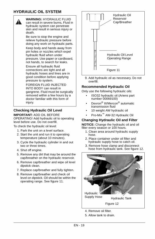
level on dipstick. Oil should be within the operating range. See figure 11.
9. Add hydraulic oil as necessary. Do not overfill.
Recommended Hydraulic OilOnly use the following hydraulic oils:
• ISO32 hydraulic oil (Ariens part number 00069100)
• Dexron® III/Mercon® automatic transmission fluid
• 10 weight AW hydraulic oil
• Pro-Mix™ AW-32 Hydraulic Oil
Changing Hydraulic Oil and FilterNOTICE: Change the hydraulic oil and oil filter every season or 100 hours.
1. Clean area around hydraulic supply hose.
2. Place container under oil filter and hydraulic supply hose to catch oil.
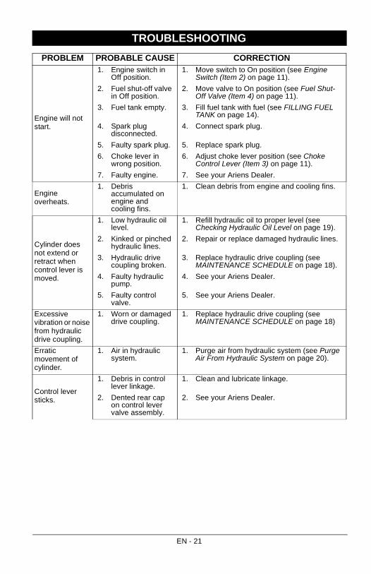
3. Remove hose clamp and disconnect hose from hydraulic tank. See figure 12.
4. Remove oil filter. 5. Allow tank to drain.
WARNING: HYDRAULIC FLUID can result in severe burns. Fluid in hydraulic system can penetrate skin and result in serious injury or death.Be sure to stop the engine and relieve hydraulic pressure before doing any work on hydraulic parts.Keep body and hands away from pin holes or nozzles which expel hydraulic fluid when under pressure. Use paper or cardboard, not hands, to search for leaks.Ensure all hydraulic fluid connections are tight and all hydraulic hoses and lines are in good condition before applying pressure to system.FOREIGN FLUID INJECTED INTO BODY can result in gangrene. Fluid must be surgically removed within a few hours by a doctor familiar with this form of injury.
Figure 11
Hydraulic Oil Level Operating Range
Hydraulic Oil Reservoir Cap/Breather
Figure 12
Hydraulic Supply Hose Hydraulic Tank
EN - 19

6. Reinstall hydraulic suction hose and tighten hose clamp.
7. Lubricate rubber gasket on new oil filter with clean hydraulic oil.
8. Spin new oil filter onto filter housing until it makes contact. Tighten oil filter another 1/2 turn.
9. Add new oil to the oil tank.10. Check hydraulic oil level.11. Properly dispose of waste oil.
Purge Air From Hydraulic System1. With the engine running, extend the
hydraulic cylinder out fully and then retract fully.
2. Repeat 4 – 5 times. Erratic movement in the hydraulic cylinder indicates that there is air in the system.
3. Stop the engine and check the hydraulic oil level. Add if necessary.
4. Repeat extending and retracting of hydraulic cylinder unit motion is consistent and smooth in both directions.
5. Ensure that hydraulic oil is at proper level.
IMPORTANT: At this point a large amount of hydraulic oil has been drawn into the hydraulic cylinder and hoses. Be sure to refill the oil reservoir to prevent pump damage.
SHORT TERMNEVER spray unit with high pressure water or store unit outdoors.Inspect unit for visible signs of wear, breakage or damage.Keep all nuts, bolts and screws properly tightened and know unit is in safe working condition.Store unit in a cool, dry protected area.Protect bare-metal areas with a light coat of oil or anti-rust compound.
LONG TERMPerform all steps found in Short Term storage.Touch up all scratched painted surfaces.Remove weight from wheels by putting blocks under frame or axle.
Fuel SystemGasoline left in the fuel system for extended periods without a stabilizer will deteriorate, resulting in gum deposits in the system. These deposits can damage the carburetor and the fuel hoses, filter and tank. Prevent deposits from forming in the fuel system during storage by adding a quality fuel stabilizer to the fuel. Follow the recommended mix ratio found on the fuel stabilizer container.To treat the fuel system for storage:
1. Add fuel stabilizer (Ariens part number 00592900) according to manufacturer’s instructions.
2. Run engine for at least 10 minutes after adding stabilizer to allow it to reach the carburetor.
NEVER store the engine with fuel in the fuel tank inside of a building with potential sources of ignition.
To Take the Unit Out of Storage1. Refer to the engine service manual to
prepare the engine for service.2. Put fresh, clean fuel in the fuel tank.3. Begin the maintenance schedule.
STORAGE
EN - 20
TROUBLESHOOTING
PROBLEM PROBABLE CAUSE CORRECTION
Engine will not start.
1. Engine switch in Off position.
1. Move switch to On position (see Engine Switch (Item 2) on page 11).
2. Fuel shut-off valve in Off position.
2. Move valve to On position (see Fuel Shut-Off Valve (Item 4) on page 11).
3. Fuel tank empty. 3. Fill fuel tank with fuel (see FILLING FUEL TANK on page 14).
4. Spark plug disconnected.
4. Connect spark plug.
5. Faulty spark plug. 5. Replace spark plug.
6. Choke lever in wrong position.
6. Adjust choke lever position (see Choke Control Lever (Item 3) on page 11).
7. Faulty engine. 7. See your Ariens Dealer.
Engine overheats.
1. Debris accumulated on engine and cooling fins.
1. Clean debris from engine and cooling fins.
Cylinder does not extend or retract when control lever is moved.
1. Low hydraulic oil level.
1. Refill hydraulic oil to proper level (see Checking Hydraulic Oil Level on page 19).
2. Kinked or pinched hydraulic lines.
2. Repair or replace damaged hydraulic lines.
3. Hydraulic drive coupling broken.
3. Replace hydraulic drive coupling (see MAINTENANCE SCHEDULE on page 18).
4. Faulty hydraulic pump.
4. See your Ariens Dealer.
5. Faulty control valve.
5. See your Ariens Dealer.
Excessive vibration or noise from hydraulic drive coupling.
1. Worn or damaged drive coupling.
1. Replace hydraulic drive coupling (see MAINTENANCE SCHEDULE on page 18)
Erratic movement of cylinder.
1. Air in hydraulic system.
1. Purge air from hydraulic system (see Purge Air From Hydraulic System on page 20).
Control lever sticks.
1. Debris in control lever linkage.
1. Clean and lubricate linkage.
2. Dented rear cap on control lever valve assembly.
2. See your Ariens Dealer.
EN - 21
* Requires purchase of 71701300 Light Kit.
SERVICE PARTSSee your authorized Ariens dealer for genuine OEM service parts.
Part No. Qty Description
03931900 1 Hydraulic Oil Filter
21100120 1 Air Filter
21100122 1 Spark Plug
00069100 AR Hydraulic Oil – ISO 32, 2.5 Gal (9.5 L)
04651900 1 Drive Coupler Alignment Tool
ACCESSORIESSee your authorized Ariens dealer to add these optional accessories to your unit.
Part No. Description
71703300 Brake Light Bracket Kit *
71703200 License Plate Holder With Light *
71701500 Engine Cover Kit
71702000 Log Splitter Cover Kit
00592900 Fuel Stabilizer 4 oz.
71703000 Fender Kit
71702100 Handle Draw Bar Kit
71702900 Work Table Kit
SPECIFICATIONSModel Number 917011 917012
Model 22-Ton Log Splitter 25-Ton Log Splitter
Engine
Engine Subaru
Engine Model Number EA175V
Displacement – Cu. In. (cc) 10.6 (174)
Max RPM 3800±100
Oil Capacity – Pt. (L) 1.3 (.6)
Fuel Tank Capacity Qt. (L) 1.2 (1.3)
Fuel Octane Rating Refer to Engine Manual
Hydraulic System Capacity – Gal. (L) 4.5 (17)
Splitting Force – Ton (kg) 22 (22353) 25 (25401)
Cylinder Cycle Time – Seconds 12 16
Bed Capacity: Log Length – in. (cm) 25 (63.5)
Size and Weight
Length: Horizontal Position – in. (cm) 84.7 (215.1)
Length: Vertical Position – in. (cm) 39.75 (101)
Width – in. (cm) 37.6 (95.5)
Height: Horizontal Position – in. (cm) 46.25 (117.5)
Height: Vertical Position – in. (cm) 49.4 (125.5)
Weight – lbs. (kg) 374 (169.6) 424 (192.3)
Tires
Tire Size – in. 4.80/4.00 x 8
Tire Pressure – psi (kPa) 30 (137.9)
Maximum Towing Speed – mph (kph) 45 (72.4)
Hitch Coupler – in. (cm) 2 (5.1)
EN - 22
Sno-Thro®, Sno-Tek® and Chore Performing Equipment
Limited Warranty
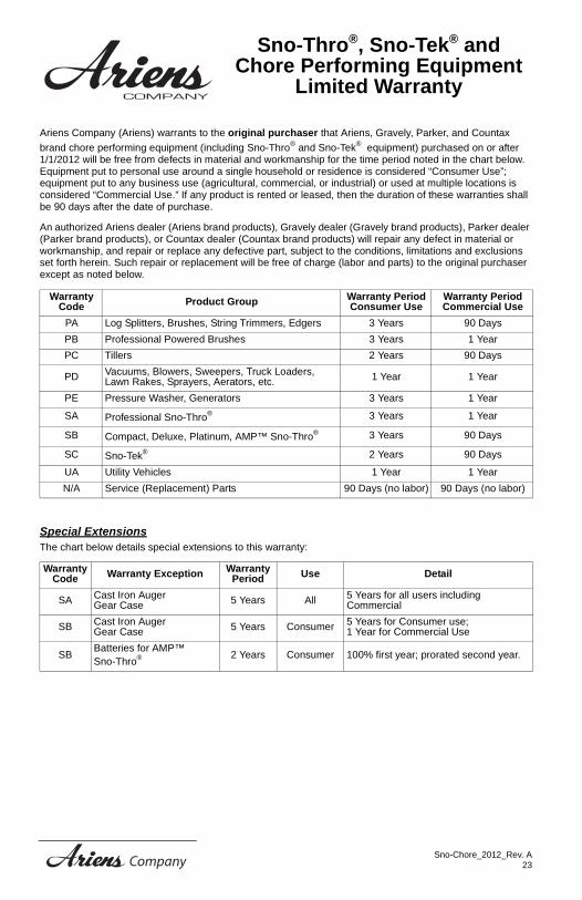
Ariens Company (Ariens) warrants to the original purchaser that Ariens, Gravely, Parker, and Countax
brand chore performing equipment (including Sno-Thro® and Sno-Tek® equipment) purchased on or after 1/1/2012 will be free from defects in material and workmanship for the time period noted in the chart below. Equipment put to personal use around a single household or residence is considered “Consumer Use”; equipment put to any business use (agricultural, commercial, or industrial) or used at multiple locations is considered “Commercial Use.” If any product is rented or leased, then the duration of these warranties shall be 90 days after the date of purchase.
An authorized Ariens dealer (Ariens brand products), Gravely dealer (Gravely brand products), Parker dealer (Parker brand products), or Countax dealer (Countax brand products) will repair any defect in material or workmanship, and repair or replace any defective part, subject to the conditions, limitations and exclusions set forth herein. Such repair or replacement will be free of charge (labor and parts) to the original purchaser except as noted below.
Special ExtensionsThe chart below details special extensions to this warranty:
Warranty Code Product Group Warranty Period
Consumer UseWarranty Period Commercial Use
PA Log Splitters, Brushes, String Trimmers, Edgers 3 Years 90 Days
PB Professional Powered Brushes 3 Years 1 Year
PC Tillers 2 Years 90 Days
PD Vacuums, Blowers, Sweepers, Truck Loaders, Lawn Rakes, Sprayers, Aerators, etc. 1 Year 1 Year
PE Pressure Washer, Generators 3 Years 1 Year
SA Professional Sno-Thro® 3 Years 1 Year
SB Compact, Deluxe, Platinum, AMP™ Sno-Thro® 3 Years 90 Days
SC Sno-Tek® 2 Years 90 Days
UA Utility Vehicles 1 Year 1 Year
N/A Service (Replacement) Parts 90 Days (no labor) 90 Days (no labor)
Warranty Code Warranty Exception Warranty
Period Use Detail
SA Cast Iron Auger Gear Case 5 Years All 5 Years for all users including
Commercial
SB Cast Iron Auger Gear Case 5 Years Consumer 5 Years for Consumer use;
1 Year for Commercial Use
SBBatteries for AMP™ Sno-Thro® 2 Years Consumer 100% first year; prorated second year.
Sno-Chore_2012_Rev. A23
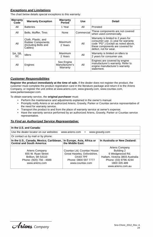
Exceptions and LimitationsThe chart below details special exceptions to this warranty:
Customer ResponsibilitiesRegister the product immediately at the time of sale. If the dealer does not register the product, the customer must complete the product registration card in the literature package and return it to the Ariens Company, or register the unit online at www.ariens.com, www.gravely.com, www.countax.com, www.parkersweeper.com.
To obtain warranty service, the original purchaser must:• Perform the maintenance and adjustments explained in the owner's manual.• Promptly notify Ariens or an authorized Ariens, Gravely, Parker or Countax service representative of
the need for warranty service.• Transport the product to and from the place of warranty service at owner's expense.• Have the warranty service performed by an authorized Ariens, Gravely, Parker or Countax service
representative.
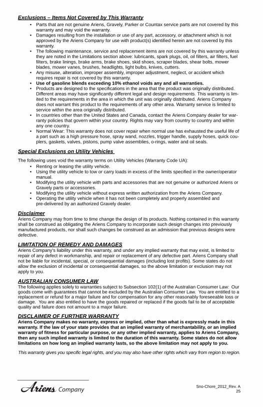
To Find an Authorized Service Representative:
Warranty Code Warranty Exception Warranty
Period Use Detail
All Batteries 1 Year All Prorated
All Belts, Muffler, Tires None Commercial These components are not covered when used commercially.
All
Cloth, Plastic, and Rubber Components (Including Belts and Cables)
Maximum 2 Years
All
Warranty is limited to 2 years for consumer use. (1 year for warranty code "PD".) Except as noted above, these components are covered for defect, not for wear.
SA, SB, SC Idlers
Maximum 2 Years
AllWarranty is limited on idlers to 2 years for consumer use.
All EnginesSee Engine
Manufacturer’s Warranty
All
Engines are covered by engine manufacturer’s warranty. Refer to engine manufacturer’s warranty statement.
In the U.S. and Canada:
Use the dealer locator on our websites: www.ariens.com • www.gravely.com
Or contact us by mail or by phone:
In the U.S., Canada, Mexico, Caribbean, Central and South America:
In Europe, Asia, Africa or the Middle East:
In Australia or New Zealand:
Ariens Company 655 W. Ryan Street Brillion, WI 54110
Phone: (920) 756 - 4688www.ariens.com
Countax Ltd, Countax HouseGreat Haseley, Oxfordshire,
OX44 7PFPhone: 0800 597 7777
www.countax.com
Ariens CompanyBuilding 2
6 Wedgewood Rd.Hallam, Victoria 3803 Australia
Phone: (03) 9796 42441800 335 489
www.ariens.com.au
Sno-Chore_2012_Rev. A24
Exclusions – Items Not Covered by This Warranty• Parts that are not genuine Ariens, Gravely, Parker or Countax service parts are not covered by this
warranty and may void the warranty.• Damages resulting from the installation or use of any part, accessory, or attachment which is not
approved by the Ariens Company for use with product(s) identified herein are not covered by this warranty.
• The following maintenance, service and replacement items are not covered by this warranty unless they are noted in the Limitations section above: lubricants, spark plugs, oil, oil filters, air filters, fuel filters, brake linings, brake arms, brake shoes, skid shoes, scraper blades, shear bolts, mower blades, mower vanes, brushes, headlights, light bulbs, knives, cutters.
• Any misuse, alteration, improper assembly, improper adjustment, neglect, or accident which requires repair is not covered by this warranty.
• Use of gasoline blends exceeding 10% ethanol voids any and all warranties.• Products are designed to the specifications in the area that the product was originally distributed.
Different areas may have significantly different legal and design requirements. This warranty is lim-ited to the requirements in the area in which the unit was originally distributed. Ariens Company does not warrant this product to the requirements of any other area. Warranty service is limited to service within the area originally distributed.
• In countries other than the United States and Canada, contact the Ariens Company dealer for war-ranty policies that govern within your country. Rights may vary from country to country and within any one country.
• Normal Wear: This warranty does not cover repair when normal use has exhausted the useful life of a part such as a high pressure hose, spray wand, nozzles, trigger handle, supply hoses, quick cou-plers, gaskets, valves, pistons, pump valve assemblies, o-rings, water and oil seals.
Special Exclusions on Utility Vehicles
The following uses void the warranty terms on Utility Vehicles (Warranty Code UA):• Renting or leasing the utility vehicle.• Using the utility vehicle to tow or carry loads in excess of the limits specified in the owner/operator
manual. • Modifying the utility vehicle with parts and accessories that are not genuine or authorized Ariens or
Gravely parts or accessories. • Modifying the utility vehicle without express written authorization from the Ariens Company.• Operating the utility vehicle when it has not been completely and properly assembled and
pre-delivered by an authorized Gravely dealer.
DisclaimerAriens Company may from time to time change the design of its products. Nothing contained in this warranty shall be construed as obligating the Ariens Company to incorporate such design changes into previously manufactured products, nor shall such changes be construed as an admission that previous designs were defective.
LIMITATION OF REMEDY AND DAMAGESAriens Company's liability under this warranty, and under any implied warranty that may exist, is limited to repair of any defect in workmanship, and repair or replacement of any defective part. Ariens Company shall not be liable for incidental, special, or consequential damages (including lost profits). Some states do not allow the exclusion of incidental or consequential damages, so the above limitation or exclusion may not apply to you.
AUSTRALIAN CONSUMER LAWThe following applies solely to warranties subject to Subsection 102(1) of the Australian Consumer Law: Our goods come with guarantees that cannot be excluded by the Australian Consumer Law. You are entitled to a replacement or refund for a major failure and for compensation for any other reasonably foreseeable loss or damage. You are also entitled to have the goods repaired or replaced if the goods fail to be of acceptable quality and failure does not amount to a major failure.
DISCLAIMER OF FURTHER WARRANTYAriens Company makes no warranty, express or implied, other than what is expressly made in this warranty. If the law of your state provides that an implied warranty of merchantability, or an implied warranty of fitness for particular purpose, or any other implied warranty, applies to Ariens Company, then any such implied warranty is limited to the duration of this warranty. Some states do not allow limitations on how long an implied warranty lasts, so the above limitation may not apply to you.
This warranty gives you specific legal rights, and you may also have other rights which vary from region to region.
Sno-Chore_2012_Rev. A25

655 West Ryan StreetBrillion, WI 54110
920-756-4688Fax 920-756-2407www.ariens.com