logic, drive control, and user interface integration - tufts university
TRANSCRIPT

Logic, Drive Control, and User Interface Integration of a Multidiscipline Kinetic
Sculpture
Submitted By Jason D. Adrian
IN PARTIAL FULFILLMENT OF THE REQUIREMENTS FOR AN
UNDERGRADUATE HONORS THESIS WITH A
BACHELOR OF SCIENCE IN COMPUTER ENGINEERING
School of Engineering
Tufts University Medford, Massachusetts
May 2004
Signature of Author: Jason D. Adrian
Committee: Professor Joseph P. Noonan Dept. of Electrical and Computer Engineering Tufts University
Committee: Professor Chris Rogers Department of Mechanical Engineering Tufts University
Committee Chair: Professor Chorng Hwa Chang Dept. of Electrical and Computer Engineering Tufts University
© Copyright 2004, by Jason Adrian

Abstract Five diverse disciplines including mechanical, electrical, and computer
engineering in tandem with human factors and child development helped create an
interactive learning device called the kinetic sculpture. The kinetic sculpture consists of
five engaging user interfaces that control the actions inside a Rube Goldberg-like device.
The sculpture actions are controlled by DC, AC, and stepper motors along with solenoids
to control the path of the ball in the sculpture. N-channel and P-channel MOSFETs were
used extensively to control the motors and electronic components. The heart of the
modular input devices is a PIC microcontroller which interfaces with both sensor inputs
and LED output displays. The electrical and mechanical components together formed a
unique and interactive learning device for elementary school children.
i
Table of Contents
INTRODUCTION ........................................................................................................................................ 3 DESIGN......................................................................................................................................................... 4
THE SCULPTURE ....................................................................................................................................... 5 Elevator ................................................................................................................................................ 6 Gate....................................................................................................................................................... 8 Turnstile ............................................................................................................................................... 9 Funnel ................................................................................................................................................ 10 Accelerator ......................................................................................................................................... 11
THE INPUT DEVICES ............................................................................................................................... 12 Simon.................................................................................................................................................. 13 Distance Piano ................................................................................................................................... 14 Grip..................................................................................................................................................... 15 Laser Maze ......................................................................................................................................... 15 Noise ................................................................................................................................................... 16
PROTOTYPING ........................................................................................................................................ 16 PIC MICROCONTROLLERS ..................................................................................................................... 16 JDM PROGRAMMER ............................................................................................................................... 18 PROTOTYPE BOARD ................................................................................................................................ 19 MAJOR COMPONENTS............................................................................................................................. 21
IMPLEMENTATION................................................................................................................................ 24 THE SCULPTURE ..................................................................................................................................... 25
Elevator .............................................................................................................................................. 25 Gate..................................................................................................................................................... 31 Turnstile ............................................................................................................................................. 31 Funnel ................................................................................................................................................ 37 Accelerator ......................................................................................................................................... 38
INPUT DEVICES ....................................................................................................................................... 40 Simon.................................................................................................................................................. 43 Distance Piano ................................................................................................................................... 46 Grip..................................................................................................................................................... 49 Laser Maze ......................................................................................................................................... 51 Noise ................................................................................................................................................... 54
AUDIO AND VISUAL FEEDBACK .............................................................................................................. 56 POWER SUPPLY ....................................................................................................................................... 57 SCULPTURE CONTROL CIRCUIT ENCLOSURE........................................................................................ 61
ANALYSIS.................................................................................................................................................. 63 FUTURE INTEGRATION WITH THE ROBO-TABLE .................................................................................. 65
CONCLUSION........................................................................................................................................... 66 SOURCES ................................................................................................................................................... 67 APPENDIX ................................................................................................................................................. 68
1

Table Of Figures
Figure 1 - The Kinetic Sculpture ........................................................................................ 6 Figure 2 - Elevator Platform ............................................................................................... 7 Figure 3 - Top of Elevator With DC Motor........................................................................ 8 Figure 4 - Gate .................................................................................................................... 9 Figure 5 - Turnstile ........................................................................................................... 10 Figure 6 - Simulated Funnel ............................................................................................. 11 Figure 7 - Accelerator With AC Motor............................................................................. 12 Figure 8 - JDM Programmer............................................................................................. 18 Figure 9 - Custom Prototyping Board............................................................................... 21 Figure 10 - Happ Controls Large Arcade Button [4]........................................................ 23 Figure 11 - 12V Solenoid.................................................................................................. 24 Figure 12 - Elevator Circuit Diagram ............................................................................... 28 Figure 13 - Bi-Directional Elevator Circuit ...................................................................... 30 Figure 14 - Applied Motion HT23-397 Stepper ............................................................... 33 Figure 15 - Turnstile Circuit Diagram .............................................................................. 35 Figure 16 - Turnstile Circuit ............................................................................................. 36 Figure 17 - Full Step State Diagram ................................................................................. 37 Figure 18 - Funnel Solenoid Plunger ................................................................................ 38 Figure 19 - RJ-45 Pinout................................................................................................... 42 Figure 20 - External RCA and RJ-45 Jacks ...................................................................... 42 Figure 21 - All 5 Input Devices ........................................................................................ 43 Figure 22 - Simon ............................................................................................................. 44 Figure 23 - Simon Instructions and Feedback .................................................................. 45 Figure 24 - Simon Circuit Diagram .................................................................................. 46 Figure 25 - Sharp IR Sensor Theory [1] ........................................................................... 47 Figure 26 - Distance Piano................................................................................................ 48 Figure 27 - Distance Piano Instructions and Feedback..................................................... 48 Figure 28 – Distance Piano Circuit Diagram.................................................................... 49 Figure 29 – Grip................................................................................................................ 50 Figure 30 - Grip Circuit Diagram ..................................................................................... 51 Figure 31 - Laser Maze Star Detail................................................................................... 52 Figure 32 - Laser Maze Circuit Diagram.......................................................................... 53 Figure 33 - Laser Maze Plexiglas Top.............................................................................. 54 Figure 34 - Noise Circuit Diagram ................................................................................... 55 Figure 35 - Noise Input ..................................................................................................... 56 Figure 36 - Power Supply Parts Labeled .......................................................................... 59 Figure 37 - Power Supply Circuit Diagram ...................................................................... 59 Figure 38 - External View of 17 Volt Power Supply........................................................ 60 Figure 39 - Sculpture Circuit Enclosure ........................................................................... 61
2
Introduction
The Tufts Robotics Academy, started in the fall of 2002, aims to bring an
interdisciplinary team of students together to solve a problem with a robotic design. The
robotic creation is also designed to act as a teaching tool for elementary school children
to learn about basic engineering principles. This years’ team consisted of 2 electrical
engineers, 2 mechanical engineers, a human factors, and a child development major. By
working as a cohesive team, and combining the knowledge and expertise of each major,
the team designed a kinetic sculpture.
The objective of this year’s Robotics Academy project was to develop an
educational and entertaining robotic creation. This robot needed to be interesting to grade
school children while teaching them basic engineering principles through demonstration.
The inspiration for this project came from what many people know as a “Rube Goldberg”
device. Reuben Goldberg, a career cartoonist, often featured incredibly complex
machines for accomplishing a simple task in his cartoons [7]. His cartoons inspired
contests in which people tried to come up with the most interesting and complex method
to perform a set task. With this in mind, the idea of the kinetic sculpture was born.
During brainstorming sessions, the actions and events were chosen to both
illustrate engineering principles and grab the attention of grade school children. The key
difference between a typical Rube Goldberg device and the kinetic sculpture came in the
form of user interaction. Getting the children involved was important, so the addition of
input devices to control the events within the sculpture set the kinetic sculpture apart
from what has been done in the past. Rube Goldberg machines are something of a
3
spectacle where people watch the unfolding events; the kinetic sculpture, in contrast, is a
fully interactive cause and effect learning device.
The kinetic sculpture consists of two major components: the sculpture where a
ball moves through a closed loop path, and five unique input devices to control the
actions of the sculpture. The five input devices are played by children to generate a
response within the sculpture. Each input device consists of a game or task that the user
must complete to activate the next action within the sculpture.
The electrical engineering aspect of this project was to control all the moving
parts as well as provide the user interface for the kinetic sculpture. The sculpture consists
of solenoids, DC motors, AC motors, and stepper motors that need to be both controlled
and synchronized with the flow of the ball through the sculpture. Creating an interesting
and engaging experience with the kinetic sculpture is dependent on having interesting
input devices and generating the desired reaction within the sculpture. The input devices
consist of many LEDs, sensors, and microcontrollers to create interactive games and
tasks.
Design
Designing the kinetic sculpture involved all of the team members generating ideas
and evolving them based on knowledge from each discipline. Perhaps one of the most
important criteria was making the sculpture portable, so it could be brought to
classrooms. Thus, it was decided it should be able to be lifted by two adults to be
considered portable. In addition, the sculpture cycle needed to be repeatable, without any
user intervention to set it up again. It was also desirable to have the sculpture need a
4
single 110 V AC power plug, to allow the sculpture to be easily setup and placed almost
anywhere.
The Sculpture
The sculpture consists of five major events, each controlled by one of the five
input devices. The five events are each controlled by an elevator, turnstile, funnel,
accelerator, and gate [Figure 1]. These events together form a closed loop path in which
the ball starts and ends in same place. Repeatability is an important aspect of the
sculpture, and the closed loop design assures this. The starting point for the sculpture is at
the base of an elevator. The elevator event is triggered by completing the first input task,
and will lift the ball to the top of the sculpture to begin its journey. At the top of the
elevator, the ball will roll onto the track and stop at a gate. Completing the second input
station will cause the gate to rise, allowing the ball to continue down the track to the third
event. The ball then falls into a turnstile, which is activated by the third input device,
causing the turnstile to rotate dropping the ball onto the track below it. The ball then
continues along the track until it comes to the funnel. The ball is blocked from entering
the funnel until the fourth input device is completed. After going through the funnel the
ball comes to the final event, the accelerator to get the ball back to the starting point of
the sculpture. The ball is blocked from entering the accelerator until the fifth input task is
completed. Upon task completion, the ball goes into the accelerator which moves the ball
fast enough to go through a three foot diameter loop which ends back at the base of the
elevator, completing the path.
5

Constructing the sculpture required extensive interaction between the mechanical
and the computer and electrical engineers. Every event needed to be analyzed for the
feasibility of being mechanically and electrically possible. While some designs were
mechanically simple, they presented difficulties for the development of the electronics,
and visa versa.
Figure 1 - The Kinetic Sculpture
Elevator
The elevator, as the first event, is the largest single component and serves to bring
the ball from the base of the sculpture to the top to begin its journey. Unlike a traditional
elevator which is composed of gears and pulleys, this elevator moves by rotating a central
6
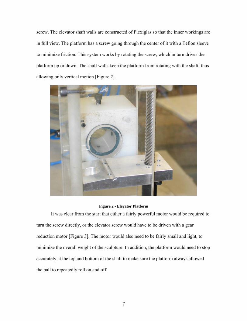
screw. The elevator shaft walls are constructed of Plexiglas so that the inner workings are
in full view. The platform has a screw going through the center of it with a Teflon sleeve
to minimize friction. This system works by rotating the screw, which in turn drives the
platform up or down. The shaft walls keep the platform from rotating with the shaft, thus
allowing only vertical motion [Figure 2].
Figure 2 - Elevator Platform
It was clear from the start that either a fairly powerful motor would be required to
turn the screw directly, or the elevator screw would have to be driven with a gear
reduction motor [Figure 3]. The motor would also need to be fairly small and light, to
minimize the overall weight of the sculpture. In addition, the platform would need to stop
accurately at the top and bottom of the shaft to make sure the platform always allowed
the ball to repeatedly roll on and off.
7
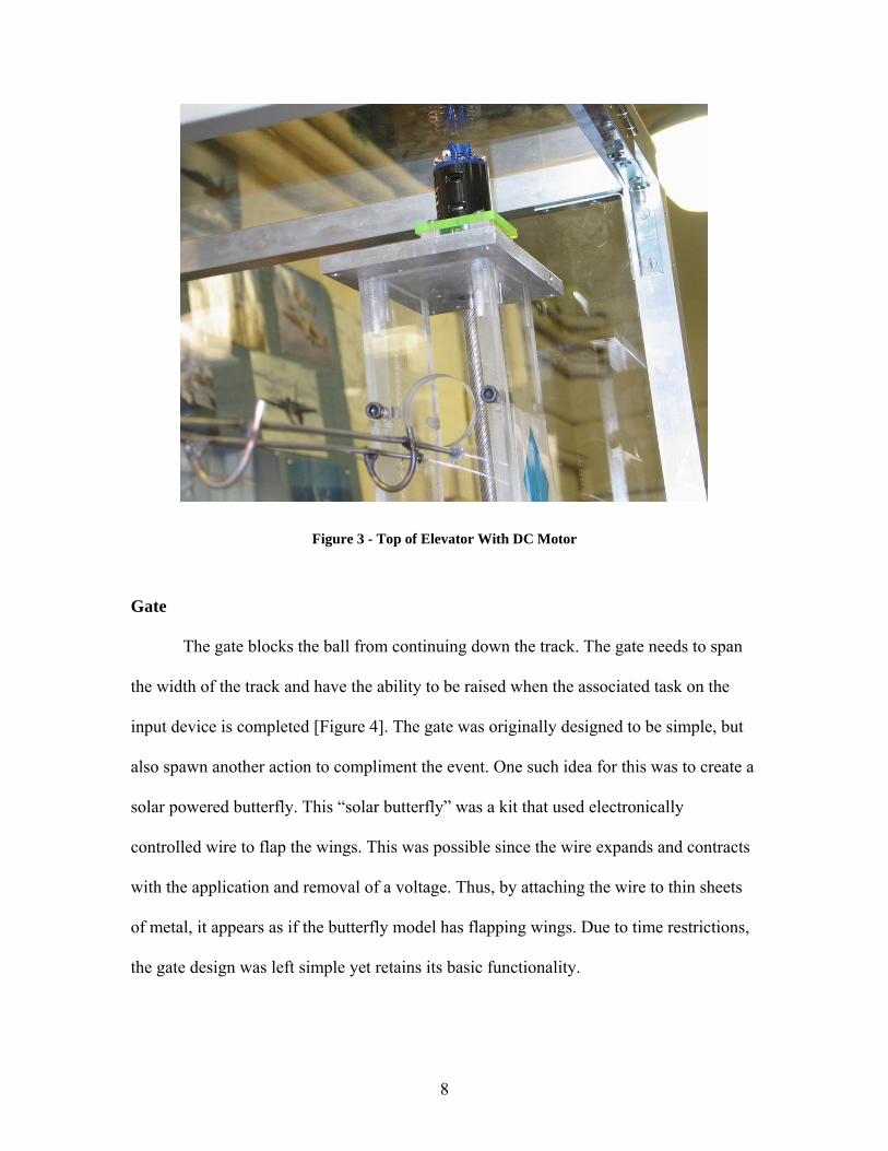
Figure 3 - Top of Elevator With DC Motor
Gate
The gate blocks the ball from continuing down the track. The gate needs to span
the width of the track and have the ability to be raised when the associated task on the
input device is completed [Figure 4]. The gate was originally designed to be simple, but
also spawn another action to compliment the event. One such idea for this was to create a
solar powered butterfly. This “solar butterfly” was a kit that used electronically
controlled wire to flap the wings. This was possible since the wire expands and contracts
with the application and removal of a voltage. Thus, by attaching the wire to thin sheets
of metal, it appears as if the butterfly model has flapping wings. Due to time restrictions,
the gate design was left simple yet retains its basic functionality.
8

Figure 4 - Gate
Turnstile
The turnstile event is modeled after a waterwheel. The wheel consists of many
compartments that are large enough to hold the ball, and turns on a central axis [Figure
5]. When the ball rolls into the wheel, it should stay there until the user has completed an
input task. Upon task completion, the wheel will rotate and drop the ball onto the track
below. The wheel itself is fairly heavy, so a motor with strong holding power is needed to
control the angular momentum of the wheel.
9
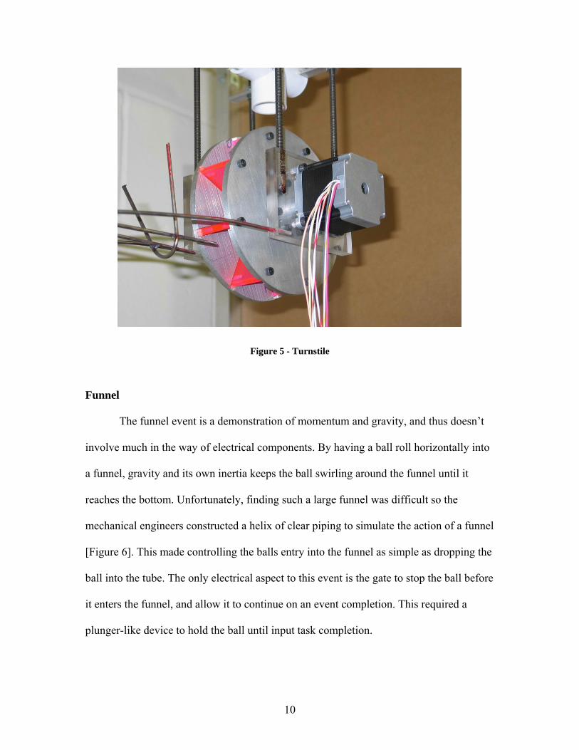
Figure 5 - Turnstile
Funnel
The funnel event is a demonstration of momentum and gravity, and thus doesn’t
involve much in the way of electrical components. By having a ball roll horizontally into
a funnel, gravity and its own inertia keeps the ball swirling around the funnel until it
reaches the bottom. Unfortunately, finding such a large funnel was difficult so the
mechanical engineers constructed a helix of clear piping to simulate the action of a funnel
[Figure 6]. This made controlling the balls entry into the funnel as simple as dropping the
ball into the tube. The only electrical aspect to this event is the gate to stop the ball before
it enters the funnel, and allow it to continue on an event completion. This required a
plunger-like device to hold the ball until input task completion.
10

Figure 6 - Simulated Funnel
Accelerator
The physics behind designing an accelerator capable of propelling a large steel
ball bearing through a loop with a diameter of nearly three feet is a daunting task. The
mechanical engineers built an accelerator consisting of two shafts meshed together with
gears [Figure 7]. Thus, rotating either one of the shafts spins both shafts at the same
velocity. Attached to the shafts are foam wheels sized to allow the ball to fit snugly
between them. To make this system work, a motor was needed to rotate one of the shafts
at an incredibly high speed so that when the ball enters one side, it gets accelerated
through the wheels and shoots out the other side at a high enough velocity to make it
through the loop.
11
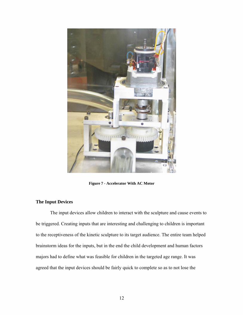
Figure 7 - Accelerator With AC Motor
The Input Devices
The input devices allow children to interact with the sculpture and cause events to
be triggered. Creating inputs that are interesting and challenging to children is important
to the receptiveness of the kinetic sculpture to its target audience. The entire team helped
brainstorm ideas for the inputs, but in the end the child development and human factors
majors had to define what was feasible for children in the targeted age range. It was
agreed that the input devices should be fairly quick to complete so as to not lose the
12

attention of the children. In addition, they should be as hands on as possible to get the
children actively involved.
Many of the ideas brought to light would require complex sensors and circuits.
Components such as distance sensors, photo-sensors, pressure sensors, and temperature
sensors were conceived to implement the input devices. Simple tasks such as measuring
the distance from an input device to a child’s hand would require the complex hardware
to be concealed from the user. The input devices were expected to exercise basic
principles such as cause and effect and memorization. The inputs also needed to be
dynamic, where the tasks varied each time to retain the attention of the children.
Five input devices were chosen to control the sculpture and provide a variety of
tasks for the children. One of the tasks was similar to the popular Simon game, where
children needed to perform pattern recognition. The “distance piano” required children to
recreate a musical note by varying the height of their hand above the input device. A
high-tech version of connect the dots with a laser is known as “laser maze”. Both the
“grip” input and the “noise” input require the children to aim for a target level either with
their voice or a pressure sensitive grip.
Simon
The classical childhood game Simon seemed a logical choice of an input device
with respect to the age of the children the sculpture is designed for. The rules of Simon
are rather intuitive, and most children have played a similar game at some point in their
lives. Simon also develops and exercises memorization skills in an entertaining and
interactive way. The Simon-like game chosen for the input device always requires a
13

pattern of four lights instead of varying the length of the pattern like the commercial
game does.
Simon consists of four buttons, each of a unique color, that are used as inputs for
the game. The buttons light up to demonstrate the pattern to follow or show when they
have been pressed. The game is played by observing a sequence of buttons lighting up,
followed by the user pressing the buttons in the same order. If the user mimics the
sequence correctly, they complete the input task. If the user makes an incorrect choice, a
new random sequence is displayed so they are able to try again.
Distance Piano
The “distance piano” input evolved from the interest in having music related
input, as well as the desire to use an Infra-Red (IR) distance sensor. Using a distance
sensor, the user can interact with the input device without physically touching it, which
would definitely impress elementary school children. The distance piano allows children
to play musical tones by varying the height of their hand above the sensor. The goal was
to make accurate representation of musical notes audible and have the children match the
given note. This approach alone might be confusing or difficult for those without musical
experience, so it was decided that this input should also have graphical note displays and
feedback. There are 13 possible notes: 7 treble notes, and 6 bass notes.
The distance piano plays a random note for the user to mimic by varying the
height of their hand above the sensor. When the user thinks they have matched the note,
they press a button to confirm their selection. The game requires three musical note
matches to win. As with all the input stations, there is of course visual feedback to let the
14
user know if they are right or wrong, but this station also uses audible feedback to
compliment the visual. The correct and incorrect tones add to the overall musical motif of
the distance piano.
Grip
The grip input allows the user to squeeze a handle grip to meet a target pressure
amount. There is a corresponding bar graph on the input station to indicate how hard the
user is squeezing the grip. The bar graph has eight lights in four colors showing the
pressure level. The scale goes from green at the bottom for the least pressure, then yellow
orange and finally red for the most pressure. The input station will display a random
pressure level via a blinking light that the user has to match. The user in turn squeezes the
grip until the target level is reached and presses a button to confirm their choice. A
successful match completes the task, whereas an incorrect pressure will generate a new
random pressure for the user to try.
Laser Maze
Laser Maze is essentially a high-tech version of “connect the dots”. Instead of a
pencil and paper, a laser is used to connect the dots. There are ten “dots”, or targets, that
comprise the shape of a star. Each point is labeled with a number, so the user can connect
the targets in the correct order. The user has to use the laser to connect the dots in
ascending order, and a false move forces the user to restart from the beginning. The user
knows when a target has been hit when a nearby light illuminates to confirm the action.
Upon completing the ten targets in order, the star flashes to confirm a victory for the user.
15

Noise
The noise input device was designed to have the user match a randomized volume
level with their voice. The user is free to make any sounds possible, but they have to
continue to hold the target volume level for a full two seconds. Thus, simply making
random sounds will not complete the task, only deliberate and constant sounds will
trigger the event completion. The target sound range goes between requiring a sound
slightly above a whisper to just above a normal conversation voice. This was chosen so
that the children would not scream or otherwise act overly unruly.
Prototyping
Controlling a complex sculpture and creating five input devices with the
complexity envisioned in the brainstorming sessions required the use of powerful
microcontrollers. While speed wasn’t a major concern, the important criteria were the
number of input and output pins due to the complexity of the designs. With several major
brands of microcontrollers available on the market, choosing one with a wide range of
models and a relatively inexpensive programmer was important. Use of a microcontroller
stamp, which is a microcontroller based board that can be programmed with a high-level
language, was not considered due to price. In addition, using an OOPic or BASIC stamp
produces inefficient and slow code, with less access to a microcontroller’s features.
PIC Microcontrollers
16

Research into microcontrollers led to Microchip’s PIC microprocessor line [5].
The PIC line consists of hundreds of different microcontrollers ranging from 8 to 64 pins,
and a host of features such as Analog to Digital conversion, pulse width modulation
(PWM) ports, and more. It was also discovered that many robotics projects used the
PICs because of their many features as well as a low cost to feature ratio. One of the most
important aspects considered when choosing the PIC was the many programmers
available for this line of microcontrollers. One of the best aspects of the PIC
microcontroller is that Microchip has a sampling program which allows the PICs to be
used for free.
Research into popular PIC chips pointed to two chips as the most commonly used.
The 16F84A, an 18 pin PIC, was incredibly popular and many websites were dedicated
just to this microcontroller. The other popular chip was the 16F877A which features 40
pins, thus making it more appropriate for larger projects. With 33 of the 40 pins on the
16F877A available as I/O pins, including 8 channels of 10bit analog to digital
conversion, and a generous 8192 instructions of space in the FLASH memory, the PIC is
suitable for very complex tasks.
Programming the PIC microcontrollers can be easily done with Microchip’s
MPLAB software and one of their PRO MATE II programmers. While the software is
free to download, the official Microchip IC programmers cost several hundred dollars. To
save money on the programmer, many PIC related websites and discussion forums were
consulted for other alternatives. It turns out that there are many programmer designs that
should work for the PIC 16F84A. Designs ranged from only a few resistors to more
17

complex designs costing over $100 in parts alone. One of the most popular programmers,
which falls mid-range in terms of cost and complexity, was the JDM programmer.
JDM Programmer
The JDM programmer is a fairly simple design consisting of several resistors,
capacitors, and zener diodes [Figure 8]. Instead of using an IC socket, a Zero Insertion
Force (ZIF) socket was chosen to simplify the process of inserting and removing the
PICs. The pin-out reference in the JDM schematic was for an older, 25 pin (d25) serial
port. Since the PC’s used only have 9 pin (d9) serial ports, a simple lookup of the pin
mappings was all that was needed to adapt the JDM design to a 9 pin connection. Below
is the modified JDM schematic used to program the PICs for this project.
Figure 8 - JDM Programmer
18

As a 3rd party programmer, the JDM is obviously not supported by MPLAB.
Thus, even though the code can be written and tested with MPLAB, it is unable to
program the PIC on the JDM programmer. To solve this, the assembly code written in
MPLAB is compiled and exported as a hexadecimal file. To copy this HEX file to the
PIC, an EEPROM programming program capable of writing to the PIC through the JDM
needed to be found. Two options worked with the JDM, IC-Prog and Pony Prog. Both
programs are freeware, and IC-Prog was chosen over Pony Prog for its fast write times
and simple interface.
Prototype Board
From the beginning, it was known that prototyping and debugging would be the
most time consuming aspect of the project. With this in mind a fast, efficient, and most
importantly portable prototyping method was needed. The scale of the sculpture is
sufficiently large that the individual components are too large to transport to a lab, so the
circuitry would need to be brought to the machine shop where the sculpture resides. The
most logical solution seemed to be to create a small prototyping board with its own
power source that could run a PIC with no other external devices needed.
There are many prototyping boards on the market that contain several power
sources, switch banks, LED’s, and a host of other input and output devices. These
prototyping systems cost a few hundred dollars and are quite large. Another drawback to
these boards is the lack of a ZIF socket, and constantly inserting and removing a PIC
from the breadboard would be damaging to the pins on the PIC. Building a prototyping
19
board from scratch would allow for a smaller device well suited for a PIC
microcontroller. It was deemed beneficial from both a financial aspect as well as a
functionality aspect to build a custom prototyping board. Before beginning constructing
such a device, a careful examination of the input and output devices was needed.
The first aspect of the prototyping board to be examined was the power
requirements. The PIC draws only 100mA to 200mA at 5V with all output ports
outputting their maximum rating of 20mA. Typical power draw for the 16F84A PIC with
no outputs in use is 2mA [5]. With such a low power draw, a small battery could easily
be used as the power source. With lots of testing, batteries would need to be a renewable
commodity, so a common battery type was selected. The choice was narrowed down to
either a 9V battery or four AAs or AAAs. A 9V was deemed better due to a smaller size
and the fact that using a 5V regulator needs an input of at least 6V, which 4 AAs or
AAAs only meet when they are fully charged.
To make the prototyping board versatile, all of the output pins should be
connected to a breadboard output so that any device could be connected. In addition,
LED outputs and switches would be needed to simulate input and output signals. Since
most PICs do not have onboard resonators, the board would also need a socket for that as
well. A resonator is needed to give the clock frequency to the PIC, which for the
16F84A’s is 4MHz. Last but not least, the board needed to have an easy method of
expansion, so input devices such as IR sensors and microphones could be connected at a
later date.
The final design utilized a 24 pin ZIF socket, which allowed the board to be used
for the 16F84A, 16F88, and any other PIC chips with 24 pins or less [Figure 9]. Two
20

banks of 8 LEDs were integrated, one on each side of the board. One of the banks used
yellow LEDs, and the other red to help differentiate outputs. By integrating a resistor
network, and tying one end to ground, the connection of an output port to an LED is as
simple as putting a jumper from the LED to the output pin. To simulate inputs, a bank of
six SPDT switches was implemented, to switch the input from either 5V or ground. If a
static input of 5V or ground was needed, there are sockets on both sides of the board
providing both outputs to reduce wire clutter. Finally, an RJ-45 jack was added to the
board that would allow the connection of any external device with 8 lines or less. With all
of these features, and nothing hard-wired, this prototype board could be used to test any
of the circuits used in the kinetic sculpture.
Figure 9 - Custom Prototyping Board
Major Components
21
There are several components, outlined below, that were used in many of the
input devices or in the sculpture itself. Standardization of parts was important to simplify
the sculpture design and allow many parts to be interchangeable. Using commonly
available parts was also crucial for repair work and future maintenance of the sculpture.
MOSFETs
When designing the motors controllers, it was obvious that the design would need
to handle substantial current. The obvious starting point was to look into high-current
transistors. Metal Oxide Semiconductor Field Effect Transistors (MOSFETs) were found
to have low on resistance, high current ratings, and fast switching rates[6]. In particular,
the Fairchild Semiconductor NDP603AL N-channel MOSFET had a good cost to feature
and high availability. The NDP603AL is rated for 25A continuous current, or up to 100A
when pulsed. The pulsed rating of 100A refers to the ability to draw a large instantaneous
current when turned on and off at a high frequency. A P-channel MOSFET was also
needed, and the IRFP9140 from International Rectifier had similar characteristics most
notably a 21A current rating with up to 84A when pulsed. Using a MOSFET instead of a
transistor saves on the overall parts costs, since the transistor would need to operate in
saturation to give the simple on-off switching needed by the sculpture motors and
components. This would require the addition of resistors for each and every transistor
used.
Arcade Buttons
22

Large, illuminated buttons were required for many of the input devices. Finding
large buttons, yet alone with a built in light, was a challenge. Collaboration with the
human factors team member led to the discovery of arcade buttons. Not only are arcade
buttons large and lit, but they are proven to be durable. Happ Controls sells many arcade
buttons, and their large round illuminated pushbutton was chosen for the input devices.
These buttons mount through a 1” diameter hole and have a 12V lamp assembly with a
micro-switch that mounts below the surface [Figure 10]. The availability of six colors
was more than ample, since the only input requiring more than one button was Simon,
which required four.
Figure 10 - Happ Controls Large Arcade Button [4]
Solenoids
Solenoids were chosen to perform the action of a gate in the sculpture mainly for
their simple operation. A solenoid is essentially an electromagnet with an iron core that
23

fits inside the electromagnetic coil [Figure 11]. When there is no current flowing through
the electromagnet, there is no electromagnetic field and the core remains at rest. When
the electromagnet is energized, the field forces the shaft into or out of the solenoid
depending on which direction the solenoid’s electromagnet is wound. The core must
either have a ledge to stop the motion, or the solenoid housing must be closed on one end
to prevent to core from shooting out the opposite end. Typically a spring is used to force
the core to its natural state, but in the case of the kinetic sculpture, gravity was used to
return the core to its resting state.
Figure 11 - 12V Solenoid
Implementation
Converting the specifications on paper into a physical entity was a time
consuming process of trial and error. By using microcontrollers, updating the code to
control the sculpture events and inputs was a simple as removing the PIC and
24
reprogramming it. By choosing to implement the sculpture in modules, each individual
unit was tested and the design validated before integrating it with the main sculpture.
The Sculpture
The sculpture involved several types of motors and controllers to regulate
these motors. Most of the circuit designs focus on how to apply and modulate the power
to a motor to get the speed and torque needed. Solenoids proved very useful to act as
gates to block the ball from continuing down the track.
Despite the complexity of the circuitry controlling the sculpture and input devices,
the setup and operation of the devices is incredibly simple. With a single power cord to
connect to the wall, the sculpture does not require multiple outlets to limit the placement
of the sculpture. A single power switch turns on the entire sculpture, at which point the
central PIC initializes and checks the status of the sculpture. The only other setup button
is a single reset button. This reset button is used to cycle all the inputs in case the ball is
partway through the sculpture, which might happen if the sculpture is turned off before
completing the entire loop. A pre-timed routine turns on each event in sequence to force
the ball to return to the starting point at the base of the elevator.
Elevator
One of the most challenging events was the elevator to transport the ball from the
end of the closed loop back to the beginning. The elevator consists of a Plexiglas
enclosure with the platform being pushed up the enclosure by a steel shaft. Turning the
shaft one direction or the other allows the platform to be raised and lowered with
25
minimum friction. To control the platform height, a DC motor was chosen to turn the
shaft since speed and torque were both important requirements. The best solution found
to balance speed, torque, and cost was a motor from a remote controlled hobby car. The
Kyosho Ion Storm motor has a maximum RPM of 23,500, but more importantly the
motor has the highest torque rating of the RC car “stock” motors, a respectable 206N/cm
[2]. At only $18, the Ion Storm is cheaper than many small motors sold for robotics use,
yet it has higher torque and RPM ratings.
High torque motors do not come without their cost, such a speed controller.
Commercial speed controllers for remote controlled cars often have reverse capabilities
on the lower end models, but the reverse does not run at full speed and torque. For the
elevator motor controller, a speed controller had to have high torque in both directions to
get the shaft to spin. With commercial speed controllers costing $70 and up, a custom
design was drafted to fit the needs of the kinetic sculpture.
Building on the research into high-current MOSFETs, such as those used in the
turnstile, a bidirectional motor controller capable of 20A sustained current was designed.
With an impedance of 0.8Ω when the motor is not rotating, the initial current draw to
start the motor was estimated to be 17V / 0.8Ω to yield a current draw of 21.25A for a
short fraction of a second. To overcome the motor’s initial rotational inertia, a far greater
current spike would be needed to overcome stiction. Stiction, or static friction, is simply
the force often associated with motors attached to a mechanical device or load. Once the
motor begins to rotate, the impedance of the motor increases and thus the current
decreases since the two are inversely proportional.
26
A traditional H-bridge design was chosen for the bidirectional elevator motor
controller, with the exception of MOSFETs being substituted for transistors. In fact, most
of the commercial remote controlled car speed controllers use N-Channel MOSFETs due
to their low on resistance and high current capabilities. The N-channel MOSFETs used
are capable of 25A, whereas the P-Channel are capable of only 21A. Since the maximum
measured draw of the motor was only 18A, this would not be a problem.
The theory behind the H-bridge uses the characteristics of N and P-Channel
substrates to control which FET’s are on at a given time. N-channel MOSFETs turn on
when the gate to source voltage is higher than the threshold voltage, or roughly 1.5V.
Below this voltage the impedance of the drain to source is very high, allowing no current
to flow which in essence is an off state. A P-channel MOSFET, on the other hand, turns
on when the gate voltage is 1.5V less than the source voltage. Thus, an N-channel
MOSFET is off when the gate to source voltage is 0V to 1.5V, and on for all voltages 1.6
to Vcc. In contrast, a P-channel MOSFET is on from 0 to Vcc – 2V, and off from Vcc –
2V to Vcc. Using these characteristics, two channels can be formed by pairing up a N and
P channel MOSFET. One channel carries current in one direction, and the other channel
carries the current in the opposite direction, giving the ability to have a bidirectional
motor controller.
The first prototype of the elevator motor used only N-channel MOSFETS. This,
however, failed to work because the N-channel MOSFETs connected to the source
voltage did not turn on. The voltage differential of the gate to source could never exceed
the threshold, thus the two N-channel MOSFETs were always off. Since the Vcc source
was 17V and this was connected to the source, and the gate was also driven with a 17V
27

signal, the difference was at most 0V. Replacing the upper N-channel MOSFETs with P-
channel part fixed this. The P-channel MOSFETs turn on when the differential is less
than -2V. Thus, when the gate signal is at Vcc, the differential of 0V turns them off.
When the gate is held low, the differential then becomes 0 –Vcc, in this case -17, and
turns the P-channel on.
Figure 12 - Elevator Circuit Diagram
The final circuit consisted of 4 N-Channel MOSFETs, 2 P-Channel MOSFETs,
and 8 Schottky diodes [Figure 12]. Two of the N-Channel MOSFETs, and both P-
channels formed the H-bridge configuration [Figure 13]. The remaining two N-channel
MOSFETs were used to boost the output of the PIC from 5V to 17V, since the DC motor
28

required 17V and the P-channel MOSFETs need a gate voltage of 17V to turn off.
Without these voltage conversion N-channel MOSFETs, a 5V signal at the P-channel
MOSFETs gate would force them to remain constantly on. Perhaps the highlight of this
motor design was the use of Schottky diodes to protect the circuit. When power is
removed from a DC motor, it acts as a generator and produces back EMF which can
damage the motor controller. The MOSFET already had small diodes integrated into the
package, but seemed unable to dissipate the current efficiently. To allow current to flow
in only one direction, two Schottky diodes in parallel were used between each MOSFET
and the motor. Since each diode is only rated to handle 10A, they had to be paired in
parallel to handle the 20A this circuit was capable of. Before adding the Schottky diodes
to the motor controller, the driver MOSFETs would become warm to the touch when the
motor was turned off due to the back EMF. When the Schottky diodes were added to the
design, no noticeable temperature increase was detectable when power was removed
from the motor.
29

Figure 13 - Bi-Directional Elevator Circuit
Controlling the speed of the motor was an important factor when creating the
elevator motor controller. To control the speed of a DC motor, the voltage input needs to
increase or decrease voltage within the range of the motor. The DC hobby motor used in
the elevator works best at 12V and below. This works well with the 25A, 17V power
supply that was built for the motor controllers. Since the supply voltage is too high for
the motor, altering the duty cycle of the output from the 17V supply can be used to lower
the voltage. Pulse width modulation proved to be an effective and simple method of
controlling the speed using the PIC microcontroller. Pulse width modulation (PWM)
produces a square wave signal with a varying distance interval between the square pulses
and length of the pulse. By altering these two variables, one can change the duty cycle,
which at high frequencies appears to the load as a constant voltage. Thus, by setting the
pulse width and distance to the same, and repeating this over a thousand times per
30

second, the output of the PWM will be seen as half of the input voltage. By adjusting the
duty cycle this way, any voltage between 0V and the input voltage can be simulated.
With the 16F84A running at 4MHz, creating a pulse width frequency from 1kHz to 2kHz
was well within the operating speed of the PIC. This specific frequency range was chosen
to mimic commercial speed controllers which run between 1kHz and 1.9kHz.
Gate
The gate event was implemented with a 12V solenoid blocking the path of the
ball. Attached to the shaft of the solenoid was a circular plastic stopper to block the entire
width of the track. One important characteristic of the chosen solenoid was its ability to
hold in the activated state for extended periods of time. Some solenoids are rated for only
a single second of continuous activation, whereas the solenoid chosen for the gate claims
extended duty with no specified limit on holding time. Thus, it was perfect for raising the
gate for 2 to 3 seconds in which the ball could easily pass. The solenoid was controlled
with an N-Channel MOSFET with the gate connected to the master PIC. The source was
grounded and the drain connected to one of the solenoid terminals. The other solenoid
terminal was tied to +12V.
Turnstile
Creating a turnstile from scratch seemed a simple goal consisting of a motor and a
multi-compartment wheel. The desired motion was either a 120 degree rotation in one
direction followed by a reverse 120 degree rotation, or a simple 360 degree rotation. The
two 120 degree rotations were chosen for the following two reasons: velocity and ball
31

delivery accuracy. To allow the ball to roll out of the turnstile, a pause was needed to
give the ball a chance to roll out before returning to the starting position. By having the
turnstile stop, the issue of the ball getting stuck between the turnstile and the track was
eliminated, as well as allowing the rotational velocity to be increased to the maximum
possible. While experimenting with the 360 degree idea, the rotational velocity needed to
be low in order to allow the ball to roll onto the track, or it had to stop at 120 and wait.
A stepper motor was chosen for the turnstile since they rotate in controlled steps
of only a few degrees, in comparison to a typical DC motor which rotates freely. The
motor chosen for the turnstile was a high torque stepper motor capable of 1.8 degree steps
[3]. Applied Motion Products sells a variety of stepper motors, and the selected model
HT23-397 comes from their high torque line [Figure 14]. The high torque and holding
power of this particular stepper required high current and a low operation voltage of 3.6
volts. The motor controller circuit consisted of 4 NDP603AL N-channel MOSFETs to
energize the four internal coils of the motor. To control the logic driving the MOSFETs, a
PIC 16F84A microcontroller was chosen as the sole logic control element. It was also
possible to control the stepper motor using prefabricated TTL (Transistor-Transistor
Logic) chips but that design requires far more IC’s ranging from timer chips to shift
registers. Perhaps the most common way to control a stepper motor is using an H-bridge
IC, which combines the logic and the power circuitry. This approach did not work for the
stepper used in the sculpture because commercially sold H-bridges only handle low
current motors under 2A.
32

Figure 14 - Applied Motion HT23-397 Stepper
The PIC was programmed to energize the 4 coils of the stepper motor in sequence
to create a clockwise and counter-clockwise motion. The PICs output consisted of four
output lines capable of drawing 25mA each from the IC. This obviously would not power
the coils in the stepper, so four N-channel MOSFETs were used. Each output line was
connected to the gate of a MOSFET, so the output current could be boosted to power the
stepper motor. In order to standardize the power source to a single computer power
supply, 5 volts was switched by the MOSFETs, instead of the rated 3.6 volts that the
stepper motor is rated for. Thus, for each of the four coils, one lead was tied to 5 volts,
and the other to the drain of the N-Channel MOSFET. The source of the MOSFET was
tied to ground, so that when the PIC outputs 5V on a data line, this is above the
MOSFETs 0.6V threshold. Thus, the MOSFET turns on, completing the circuit, and
33

energizing the coil. This implementation pulls minimum current from the PIC, and
instead uses the MOSFETs to deliver the high current needed by the stepper motor.
Running the motor from a 5V source instead of a 3.6V source forced the stepper
to run outside of its normal parameters. The internal resistance if the motor is 1.8Ω, thus
when run at the specified 3.6V calculates to a 2A current draw. When using a 5V source,
the current then becomes 5V/1.8Ω = 2.78A, nearly 40% higher than the specified current.
This was not observed to be a problem, since testing the stepper in continuous motion for
10 minutes only made the stepper lukewarm. In the sculpture, the turnstile only operates
for less than three seconds each time the ball completed the full path.
The circuit built to control the stepper is simple, consisting of only a few
components [Figure 15]. An IC socket was used to hold the PIC, so that the PIC can be
easily removed to update the code if needed. A 4MHz ceramic resonator was used to
provide the clock frequency for the PIC 16F84A, which is designed to run at 4MHz. A
resonator was chosen since it integrates a 4MHZ crystal with two capacitors to stabilize
the output. The Panasonic PX400MC resonator was chosen due to its small size thus
using little PCB space. The PX400MC package has three pins, two of which are outputs,
and the central pin is a ground. The central pin was tied to the common ground of the
circuit, and the two outputs were connected to oscillator input pins 15 and 16 on the PIC
16F84A.
34

Figure 15 - Turnstile Circuit Diagram
The “master clear” pin on the 16F84A, pin 4, was connected to 5V through a
470Ω resistor [Figure 16]. The master clear is held high, since it is an active-low input,
thus only clearing the PIC when the pin is connected to ground. The Vss input, pin 5, was
tied to ground, and Vdd input, pin 14, was connected to 5V to supply the power to the
PIC. The single input to the circuit was connected to pin 17, which is bit 0 on port A.
This input bit is controlled by the master PIC, which tells the turnstile when it should
activate. The four outputs, pins 6 to 9, represent the lower four bits on port B of the PIC.
These outputs are each connected to one of the four MOSFETs used to energize the coils
in the stepper motor. Finally, a 0.1µF tantalum capacitor was placed across the 5V and
ground lines to smooth small ripple from the power input.
35

Figure 16 - Turnstile Circuit
The program to control the turnstile is fairly simple. The single input, “turnstile
activate”, is constantly polled until a signal is detected. When the turnstile activate input
is triggered, the program begins the forward motion. After rotating 120 degrees in one
direction, several delays are called to pause the motor for roughly one second. The code
then cycles the outputs in reverse order to get the motor to the starting position. To
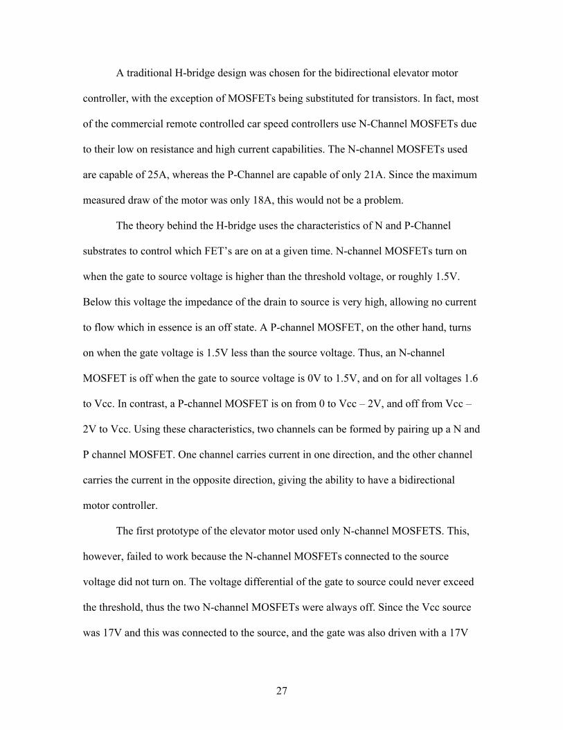
increase the torque and holding power of the motor, a full-step implementation was used.
Full-stepping is when two coils are energized simultaneously, and this leads to four
output combinations that are repeated many times [Figure 17].
State Number Winding 1 Winding 2 Winding 3 Winding 41 1 1 0 0 2 0 1 1 0
36
3 0 0 1 1 4 1 0 0 1
Figure 17 - Full Step State Diagram
Funnel
The funnel event is mostly mechanical, and the only electrical aspect was the need
to stop the ball before the funnel, and let the ball continue after a successful input task.
To create this functionality, a solenoid was placed right over the opening to the funnel
[Figure 18]. A NDP603AL N-channel MOSFET controlled by the master PIC was all that
was needed to energize the solenoid and control the gate action. A single output from the
master PIC was connected to the gate of the MOSFET, the drain was connected to one
lead on the solenoid, and the source was connected to ground. The other lead of the
solenoid is connected to +12V, but only when the gate is high is the circuit completed
allowing current to flow.
37

Figure 18 - Funnel Solenoid Plunger
Accelerator
The accelerator requirements were fairly simple, spin the drive shaft as fast as
possible to shoot the ball through a large radius loop. While this seemed a simple task,
the friction of the bearings and the gears provided a substantial load to drive. By using a
direct-drive system, with the motor directly connected to one of the shafts, the motor had
no mechanical advantage. In the design phase, this wasn’t expected to be a problem since
the RC car DC motor seemed to have plenty of torque.
Getting the motor up to full speed as fast as possible seemed as simple as
applying full voltage to the motor. This, however, had the same result as the elevator
motor which drew too much current from the computer power supply. To solve this
problem, the next attempt was to modulate the power applied by varying the pulse width.
38

To accomplish this, two N-Channel MOSFETs were controlled by a PIC 16F84A which
ramped the duty cycle from 40% to 90%. This method however also overloaded the
power supply, which is current limited to 8.5A on the 12V line.
Since the problem seemed to lie with a lack of current from the power supply,
finding a new power source was critical. The 25A, 17V power supply built for the
elevator seemed the best logical choice even though the voltage was higher than desired.
When tested, this did indeed get the accelerator to work, but lacked the speed to
accelerate the ball through the loop. In addition, the motor drew so much current that the
brushes attached to the commutator of the motor boiled off the lubricant.
The RC car motor obviously wasn’t powerful enough for the accelerator, so a new
motor had to be found. While searching for a high-RPM motor capable of meeting the
requirements of the accelerator, a vacuum motor was chosen for its high torque and
speed. Using this motor would require different logic since the original design was for a
DC motor, not an AC motor. To turn the motor on and off, a relay was used to interface
the digital control logic with the motor. This motor propelled the ball through the loop
with plenty of momentum to spare. However, not everything was perfect with this motor.
While this motor did solve the problem of accelerating the ball, it also posed new
problems in terms of noise levels. The motor is incredibly loud in operation and sends
sparks flying out from the commutator/brush junction.
To make the sculpture applicable for a classroom environment, a DC motor will
replace the vacuum motor. Several suitable motors have been found to replace the AC
motor, but all cost over $50. By using a relay for the current AC motor, changing the
39

motor to a DC replacement is simply a matter of connecting the replacement to either the
12V connector on the ATX power supply, or using the high current 17V supply.
A solenoid was needed for this input, since the ball had to be stopped before
reaching the accelerator. On completion of an input task, the master PIC sends the signal
to start the motor and wait two seconds for it to get up to speed. Then, the solenoid
release signal is sent allowing the ball to roll into the accelerator and get shot through the
loop.
Input Devices
Assembling every component together into a cohesive and simple to use kinetic
sculpture was crucial for the longevity and reliability of the sculpture. The sculpture
needed to be useable and intuitive to non-engineers, especially teachers, children, and
child development majors who will be utilizing the sculpture in a classroom setting. First
and foremost, the sculpture needs to work every time as well as being able to handle
abuse such as being turned off before the ball has completed the full path. In addition, the
sculpture needs to be easy and foolproof to setup.
Careful consideration of the needs of teachers and child development majors led
to a simple yet robust connection of the sculpture to the inputs. With five individual
inputs, it was deemed useful to be able to interchange which input device controls a
specific sculpture event. By standardizing the inputs and outputs to all of the devices, a
universal connector could be used. All of the input stations require a ground and 5V
connection for the PIC microcontrollers and devices such as sensors and LED’s. In
addition, some stations need a 12V line for the incandescent lamps used in the large
40

arcade-style buttons. Thus, three power lines needed to be included in the universal
connector. In addition, each station needs three additional control signals. One signal lets
the input device know that it is currently active and to start the game. Another two signals
are outputs from the input device, which tell the sculpture if the user completed or failed
in the task.
The original plan for the standard input device cable was to use an RJ-45
connector, the same one used for Ethernet cables. Power consumption and current draw
on the 12V line unfortunately was pushing the limits for the desired RJ-45 jack, so an
RCA plug was also used. A RJ-45 connector has a total of eight available conductors,
which would easily accommodate the 3 signal wires. The other 5 wires were split
between 5V, -5V, and ground, with two of the lines dedicated to 5V, one to -5V, and the
remaining 2 for the ground [Figure 19]. This was done to split the current over several
wires to increase the total current carrying capability of the cables. Another benefit of
using an RJ-45 jack is the availability of connectors and receptacles which connect
together with a tactile click letting the user know that a solid connection was made. With
the current draw of the 12V lamps, it was deemed beneficial to put the 12V supply on
another connector. This connector was chosen to be a RCA connector, which has two
conductors. The outer conductor was used for 12 volts and the inner for ground. The
RCA connector shares the same important characteristic of the RJ-45 jack which is that it
is polarized, thus maintaining the simple setup of the sculpture.
Pin # Connection1 Activate 2 Ground 3 Victory 4 Ground 5 Wrong
41

6 +5V 7 -5V 8 +5V
Figure 19 - RJ-45 Pinout
By using standardized connectors, the RJ-45 and the RCA, the kinetic sculpture
becomes a dynamic and versatile device [Figure 20]. Instead of a static ordering for the
input devices, they can simply be plugged into the sculpture in any order deemed
interesting or useful. This will extend the children’s interest in the kinetic sculpture as a
learning and exploration device. In addition, this setup will allow future integration with
other input devices or even a computer.
Figure 20 - External RCA and RJ-45 Jacks
All five of the input devices were built from the same overall box design. The
material used to build the boxes was medium density fiberboard (MDF) which simplified
drilling the numerous holes. The input stations have a vertical back board measuring 23”
42
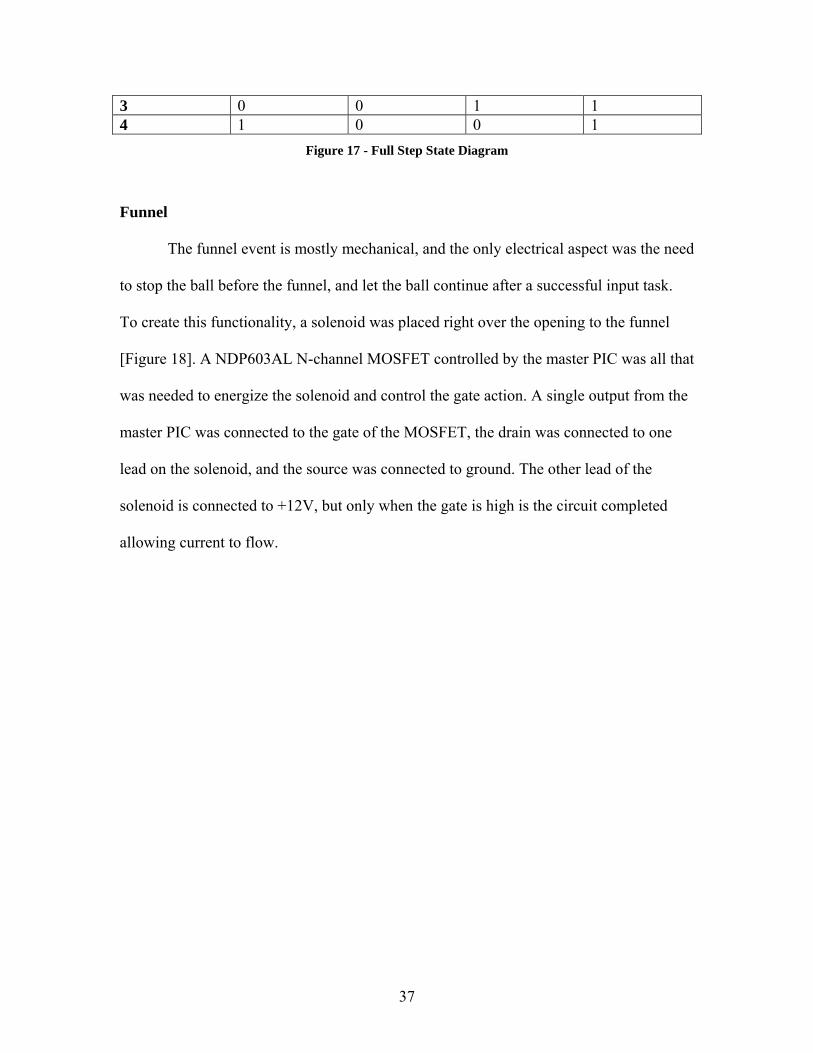
tall where most of the user feedback as well as operating instructions are placed. The
stations are 19” deep allowing for all the buttons to be placed on the surface of the
station. The width of each station is 10”, so when all five are placed side-by-side, the
total width is just over 4’ which should fit on most medium sized tables [Figure 21]. All
of the input stations were painted off-white, to give them a clean look and contrast well
with the black plastic bezels for the LEDs and buttons.
Figure 21 - All 5 Input Devices
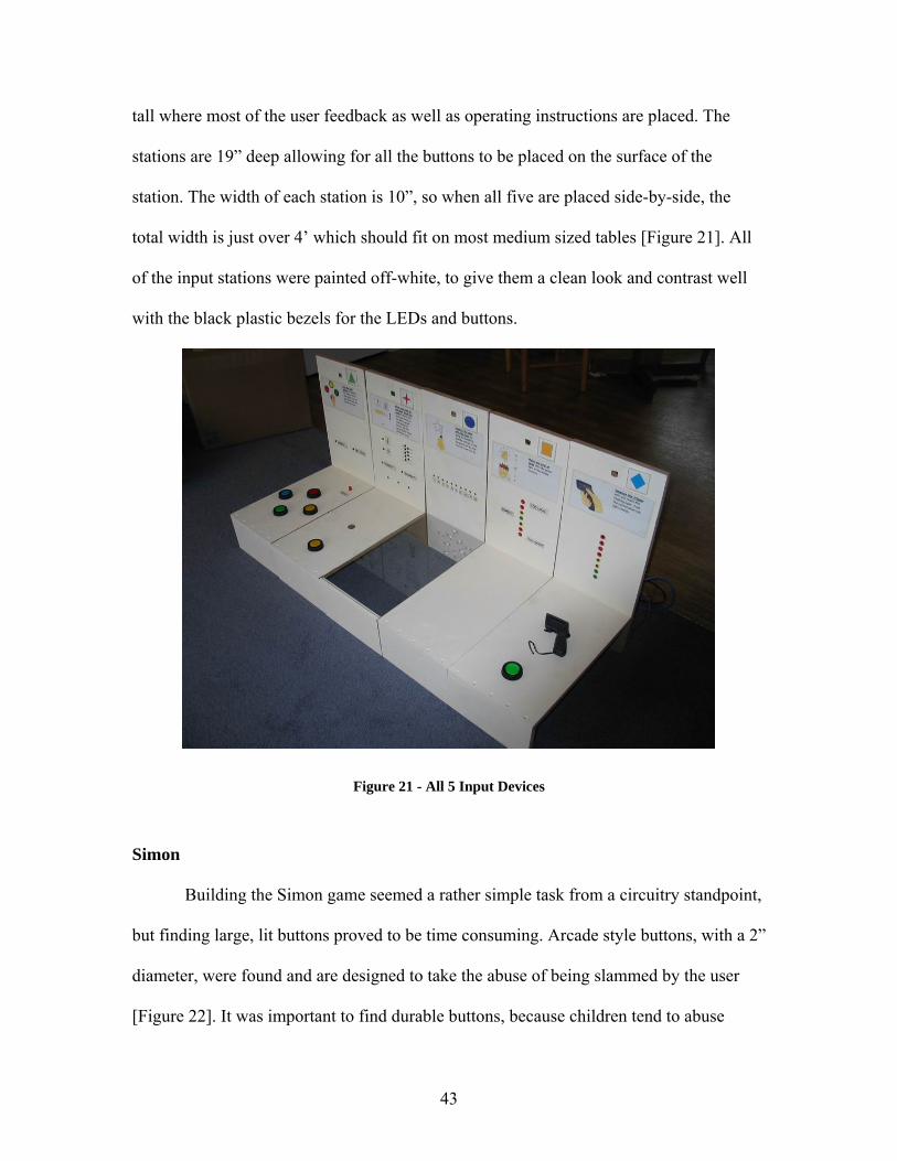
Simon
Building the Simon game seemed a rather simple task from a circuitry standpoint,
but finding large, lit buttons proved to be time consuming. Arcade style buttons, with a 2”
diameter, were found and are designed to take the abuse of being slammed by the user
[Figure 22]. It was important to find durable buttons, because children tend to abuse
43

video game buttons. Having the buttons lit was also critical in creating the look and feel
of Simon. The buttons had a protruding plastic bump to act as a key and prevent the
buttons from rotating. Once secured with the provided mounting hardware, the buttons
mounted flush with the surface of the box and did not rotate in the hole.
The buttons came with integrated 12V incandescent lamps, which draw a lot more
power than LEDs and require a 12V power source. Since the PIC can not output 12V nor
provide the current, N-Channel MOSFETs were used to interface the PIC and the lamps.
One lead from the incandescent lamp is tied to 12V, and the other lead is connected to the
drain of the MOSFET. The gate is controlled by the output from the PIC, and the source
is tied to ground [Figure 24].
Figure 22 - Simon
44
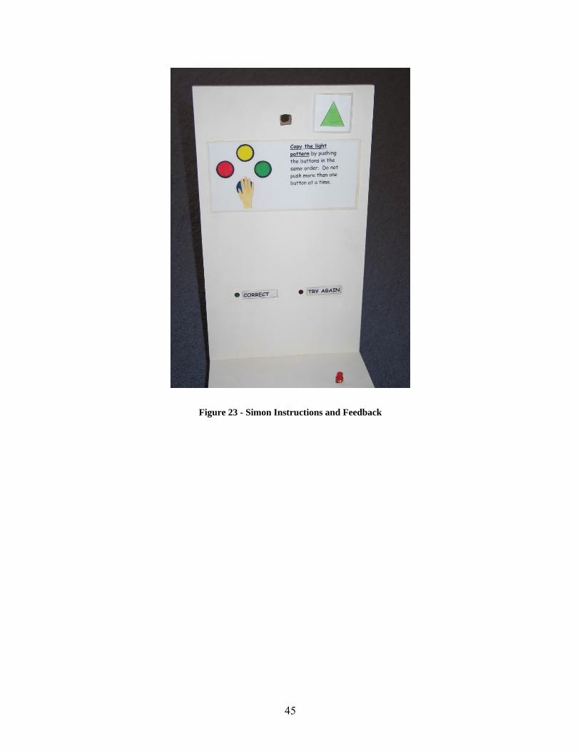
Figure 23 - Simon Instructions and Feedback
45
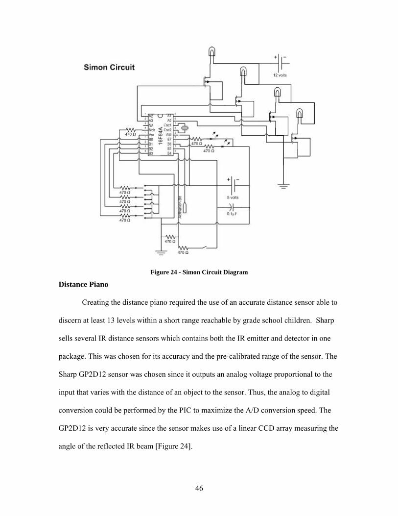
Figure 24 - Simon Circuit Diagram
Distance Piano
Creating the distance piano required the use of an accurate distance sensor able to
discern at least 13 levels within a short range reachable by grade school children. Sharp
sells several IR distance sensors which contains both the IR emitter and detector in one
package. This was chosen for its accuracy and the pre-calibrated range of the sensor. The
Sharp GP2D12 sensor was chosen since it outputs an analog voltage proportional to the
input that varies with the distance of an object to the sensor. Thus, the analog to digital
conversion could be performed by the PIC to maximize the A/D conversion speed. The
GP2D12 is very accurate since the sensor makes use of a linear CCD array measuring the
angle of the reflected IR beam [Figure 24].
46

Figure 25 - Sharp IR Sensor Theory [1]
The response curve of the sensor is smooth curve from 8cm to 80cm from the
sensor, which provides the range needed to create 13 separate notes. To block the 0cm to
8cm range from the sensor, it was mounted below the surface of the input box by 8cm. It
was mounted in a PVC tube painted matte black in an attempt to eliminate any stray IR
beams [Figure 25].
LEDs were used as indicators due to their power efficiency, size, and brightness.
Two large 8mm yellow LEDs were used to indicate the bass or treble clef [Figure 26, 27].
Nine smaller 5mm yellow LEDs indicated which of the notes was currently active. A
green and a red LED were placed below the note indicators to give visual feedback
whether the choice was correct or incorrect. Finally, three yellow LEDs line the bottom
of the input device to indicate overall progress towards completion of the three notes
needed to complete the input [Figure 28].
47

Figure 26 - Distance Piano
Figure 27 - Distance Piano Instructions and Feedback
48
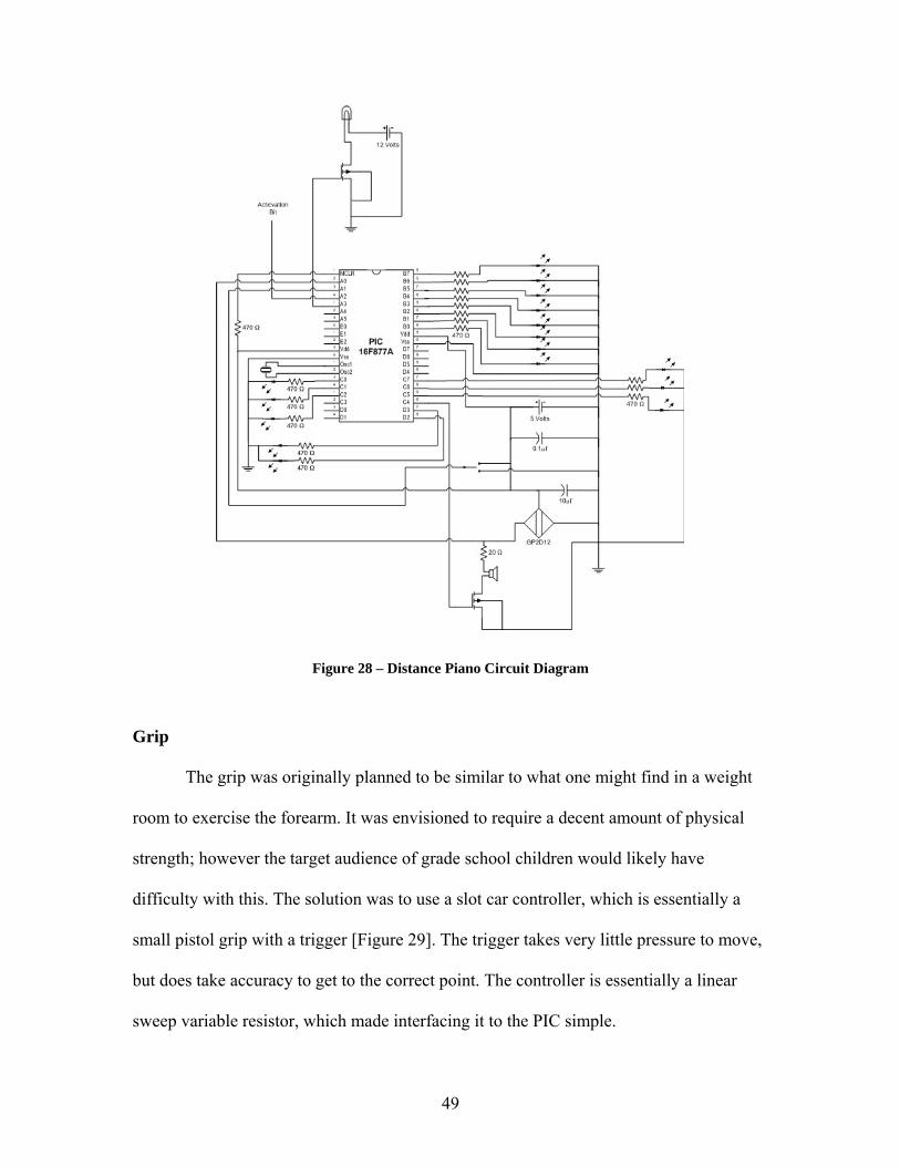
Figure 28 – Distance Piano Circuit Diagram
Grip
The grip was originally planned to be similar to what one might find in a weight
room to exercise the forearm. It was envisioned to require a decent amount of physical
strength; however the target audience of grade school children would likely have
difficulty with this. The solution was to use a slot car controller, which is essentially a
small pistol grip with a trigger [Figure 29]. The trigger takes very little pressure to move,
but does take accuracy to get to the correct point. The controller is essentially a linear
sweep variable resistor, which made interfacing it to the PIC simple.
49

Figure 29 – Grip
Eight LEDs were used to indicate the target pressure value as well as show hard
the user is gripping. An arcade style button was used to allow the user to verify their
choice. A 12V green lamp was mounted at the top center to indicate the input task has
been completed. To power the 12V lamp, an N-channel MOSFET was interfaced with the
PIC [Figure 30]. The eight LEDs were connected to the PIC with a 470Ω resistor in
series to limit the current to 10mA.
50
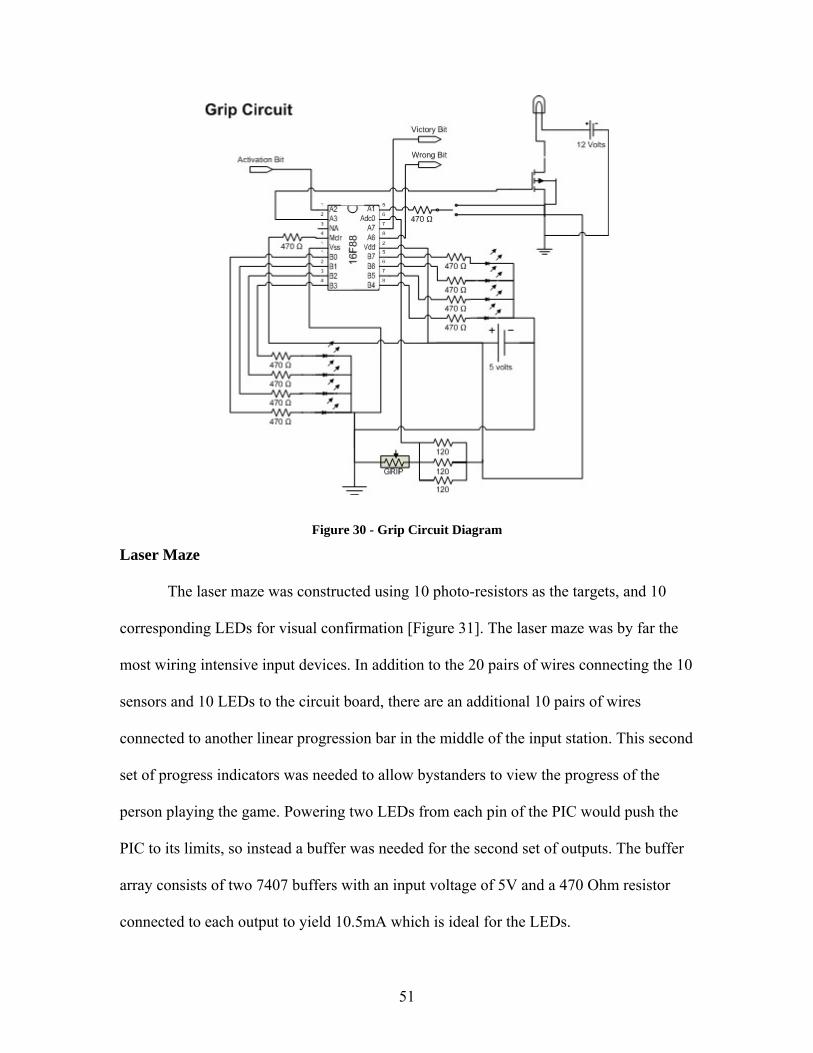
Figure 30 - Grip Circuit Diagram
Laser Maze
The laser maze was constructed using 10 photo-resistors as the targets, and 10
corresponding LEDs for visual confirmation [Figure 31]. The laser maze was by far the
most wiring intensive input devices. In addition to the 20 pairs of wires connecting the 10
sensors and 10 LEDs to the circuit board, there are an additional 10 pairs of wires
connected to another linear progression bar in the middle of the input station. This second
set of progress indicators was needed to allow bystanders to view the progress of the
person playing the game. Powering two LEDs from each pin of the PIC would push the
PIC to its limits, so instead a buffer was needed for the second set of outputs. The buffer
array consists of two 7407 buffers with an input voltage of 5V and a 470 Ohm resistor
connected to each output to yield 10.5mA which is ideal for the LEDs.
51

Figure 31 - Laser Maze Star Detail
Laser maze required 10 analog to digital conversion ports to handle the 10 targets
needed by using the start shape. Even the large PIC 16F877A only has eight analog to
digital conversion (A/D) capable ports. Thus, a two PIC design was chosen [Figure 32].
The PIC 16F84A lacks A/D conversion, but a similar PIC, the 16F88 has eight A/D
channels. Using two of the 16F88s gave 16 A/D capable inputs, which was plenty for the
laser maze.
The actual maze is concealed below a sheet of Plexiglas for safety so the children
can not look into the laser [Figure 33]. Safety was a major factor in designing the laser
maze box, since the laser can easily blind someone if misused. The laser was also fitted to
a gimble, so that the children can not remove the laser and misuse it.
52
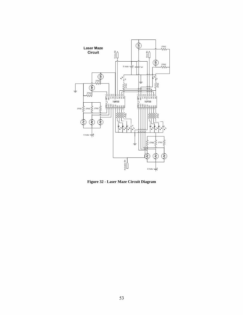
Figure 32 - Laser Maze Circuit Diagram
53
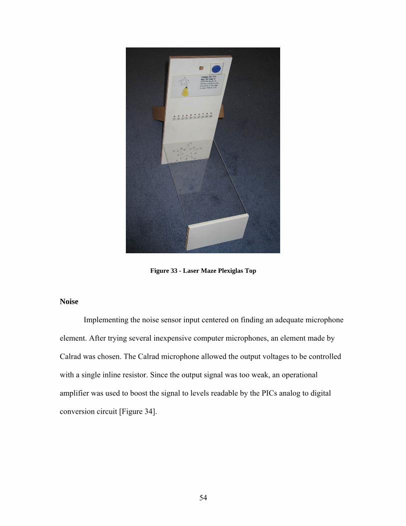
Figure 33 - Laser Maze Plexiglas Top
Noise
Implementing the noise sensor input centered on finding an adequate microphone
element. After trying several inexpensive computer microphones, an element made by
Calrad was chosen. The Calrad microphone allowed the output voltages to be controlled
with a single inline resistor. Since the output signal was too weak, an operational
amplifier was used to boost the signal to levels readable by the PICs analog to digital
conversion circuit [Figure 34].
54

Figure 34 - Noise Circuit Diagram
The back panel of the input device featured a seven element bar graph. The
central element of the graph was a single LED that represents the target volume level to
reach. On the top of the green LED, and below it are yellow, orange, and red LEDs
indicating how close the user is to the target. The user makes an audible tone to light the
central green LED and then holds this level for two full seconds to complete the input.
55
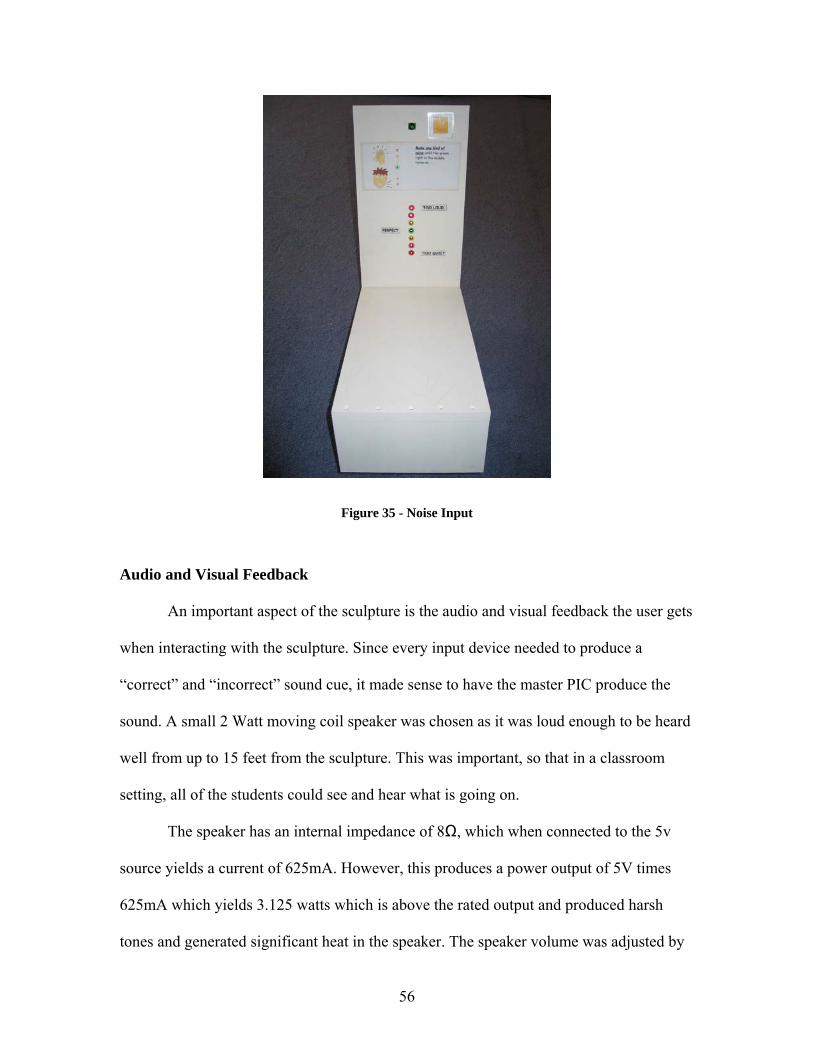
Figure 35 - Noise Input
Audio and Visual Feedback
An important aspect of the sculpture is the audio and visual feedback the user gets
when interacting with the sculpture. Since every input device needed to produce a
“correct” and “incorrect” sound cue, it made sense to have the master PIC produce the
sound. A small 2 Watt moving coil speaker was chosen as it was loud enough to be heard
well from up to 15 feet from the sculpture. This was important, so that in a classroom
setting, all of the students could see and hear what is going on.
The speaker has an internal impedance of 8Ω, which when connected to the 5v
source yields a current of 625mA. However, this produces a power output of 5V times
625mA which yields 3.125 watts which is above the rated output and produced harsh
tones and generated significant heat in the speaker. The speaker volume was adjusted by
56

putting a resistor in line with the speaker. The find the desired current, the equation
Power = Current times Voltage was used to yield the current of 0.4A ( I = 2watts / 5
volts). To decrease the current, the resistance needed to be increased according to the
following equation: R = 5V / 0.4A = 12.5Ω. The speaker’s impedance alone was 8Ω so a
5Ω was added in series to keep the speaker at just under its maximum rated output. To
provide the current needed to drive the speaker, an N-channel MOSFET was used to
power the speaker with the gate controlled by the PIC.
It was deemed important to have something special happen when the ball
completes the full path around the sculpture. A longer musical sequence plays once the
sculpture cycle is completed, but that didn’t seem exciting enough. A large blue rotating
light, such as those found on the top of a police car or some gambling machines, was
placed atop the sculpture. This light is power by AC, so it is run off a relay controlled by
the master PIC. Thus, once completing the sculpture cycle, the rotating light turns on for
the duration of the sculpture completion audio sequence.
Power Supply
A computer power supply is a great power source for many electronics projects
needing power from 5V, 12V, and -5V. However, DC motors often draw very high
instantaneous currents which strains regulated power supplies. The current demand is so
high in fact, that the power supply can not compensate and simply resets or shuts itself
off. While this is a great safety feature, it limits the supply to only powering small DC
motors. Both the elevator and the accelerator in the sculpture needed high torque and
57

high RPM DC motors. To power these high current motors, a custom power supply
would need to be built with the high current ratings in mind.
After measuring the peak current draw of the DC motor on the elevator, it was
found to be 10A at 12V when raising the elevator platform. This specification was
doubled just to be safe, so the minimum current output of the power supply should be
20A. The key to building such a high-current supply would be to find a large transformer
capable of converting 120V AC to 12V AC at high current. Searching the internet and
local electronics stores yielded only expensive transformers meeting these requirements
until a used 25A at 12.6V transformer was found for $20.
Converting an AC signal to a DC signal is fairly simple if some line ripple is
acceptable. Since a DC motor does not need an incredibly clean or stable power source,
even a substantial amount of ripple will power the motor smoothly. The output of the
secondary windings of the transformer is passed into a full wave bridge rectifier with a
35A, 400V rating [Figure 36]. This converts the sinusoidal wave of AC into a rectified
positive wave. The output is then passed through several large microfarad filter
capacitors to smooth the output waveform to a DC line voltage with a slight amount of
ripple. To get the capacitance needed to smooth the output, six electrolytic capacitors
were placed in parallel to save money over purchasing a single large capacitor. Together
the capacitors have a total capacitance of 38,800µF. This meets the recommended
capacitance found on several websites suggesting at least 1000µF per amp of output
power [Figure 37].
58
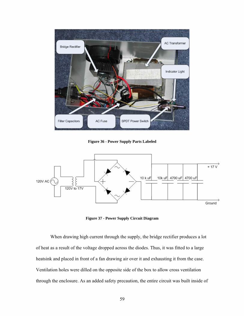
Figure 36 - Power Supply Parts Labeled
Figure 37 - Power Supply Circuit Diagram
When drawing high current through the supply, the bridge rectifier produces a lot
of heat as a result of the voltage dropped across the diodes. Thus, it was fitted to a large
heatsink and placed in front of a fan drawing air over it and exhausting it from the case.
Ventilation holes were dilled on the opposite side of the box to allow cross ventilation
through the enclosure. As an added safety precaution, the entire circuit was built inside of
59

a project box to protect against any electric shocks, and is connected to earth ground
[Figure 38]. Of course when dealing with AC, safety becomes an issue, so a fuse was
placed inline with the main AC input. The front of the enclosure has a power switch as
well as a green lamp to let the user know the power is on.
Figure 38 - External View of 17 Volt Power Supply
When the power supply was turned on for the first time, the output voltage was
just under 17V. Unfortunately, All Electronics specification of 12.6 V for the output was
an RMS value, not the peak value, but this was not specified. Thus, the output of the
transformer was 1.4 * 12.6 giving a true peak voltage of 17.64 volts. However, the bridge
rectifier consists of four diodes, thus creating a voltage drop of 0.6V volts each. Since
only two diodes have current flowing during a given part of the sine wave, the essential
voltage drop is 1.2V. Thus, the calculated output is 17.64V – 1.2V yielding a true output
of 16.44V. This matched well with the observed output voltage. Even though the desired
60
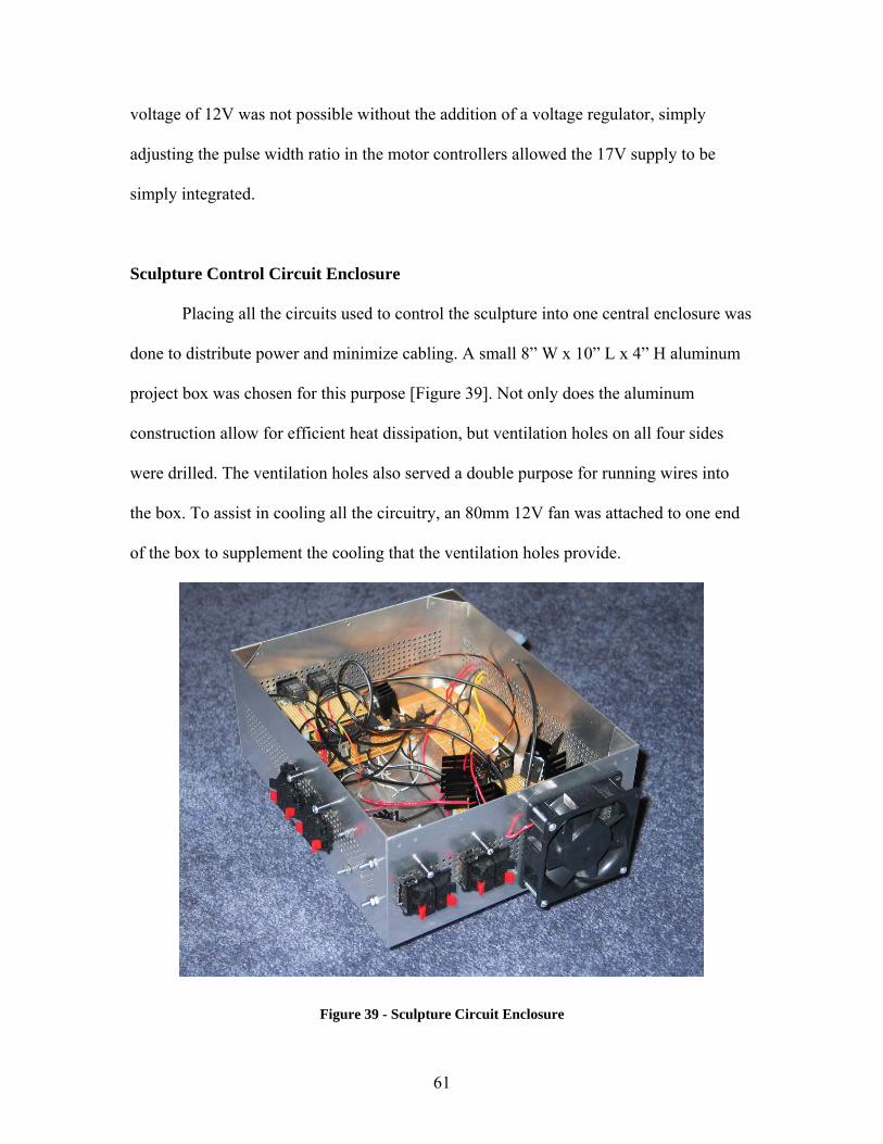
voltage of 12V was not possible without the addition of a voltage regulator, simply
adjusting the pulse width ratio in the motor controllers allowed the 17V supply to be
simply integrated.
Sculpture Control Circuit Enclosure
Placing all the circuits used to control the sculpture into one central enclosure was
done to distribute power and minimize cabling. A small 8” W x 10” L x 4” H aluminum
project box was chosen for this purpose [Figure 39]. Not only does the aluminum
construction allow for efficient heat dissipation, but ventilation holes on all four sides
were drilled. The ventilation holes also served a double purpose for running wires into
the box. To assist in cooling all the circuitry, an 80mm 12V fan was attached to one end
of the box to supplement the cooling that the ventilation holes provide.
Figure 39 - Sculpture Circuit Enclosure
61
Some of the important aspects of the kinetic sculpture are the longevity and
simple operation of the unit as a whole. Provisions needed to be made to allow easy
swapping of worn or defective parts. For the circuit enclosure, this meant not having the
motors hard-wired to the box. Instead, spring-loaded speaker terminals were chosen to
connect the motors to the enclosure. Doing this allowed the DC motors and stepper
motors to be easily connected and replaced if they failed.
When the elevator motor circuit was tested, the MOSFETs were found to generate
a significant amount of heat when frequently used. Thus, placement of the elevator motor
circuit in front of the 80mm fan was chosen to assist in cooling. This placement in the
rear of the enclosure also helped keep the length of wire from the circuit to the speaker
terminals minimal. This was advantageous since the 8AWG wire is not flexible and
would be hard to route around any circuits in the way.
The master PIC circuit was located at the front of the box so that the RJ-45 jacks
could be mounted through the front. This placement also allowed the signal wires which
control the stepper motor circuit and the elevator circuit to be as short as possible to
maintain signal integrity. By having all of the sculpture’s internal circuits in one box, the
overall wire length measures only a few inches. If each circuit was placed near the motor
it controls, then the amount of wire needed would increase exponentially causing
problems with signal integrity as well as creating a mess of wires.
The project enclosure used to house the circuits came with an aluminum lid.
Unfortunately, that hid all the internal circuitry contained within the central circuit
enclosure. To give viewers a clear view of the circuitry, the aluminum top was replaced
62
with a piece of Plexiglas. In addition, LEDs were installed in the four corners to
illuminate the enclosure further enhancing the visibility of the circuit box.
Powering the circuits in the enclosure was done via a central power distribution
board. This board was connected to a 4 pin Molex connector outside of the enclosure.
The 4 pin Molex connector is standard for all desktop computer power supplies, so
changing the power supply requires only a simple connection. Powering every circuit
within the box was as simple as connecting the enclosures’ Molex connector to the
corresponding Molex connector on the computer power supply. The internal board
consisted of low gauge wire soldered to the board to provide an easy connecting point for
the internal circuits.
Analysis
Interfacing electric circuits with mechanical devices produced many challenges
during the implementation phase of the kinetic sculpture. The small remote controlled car
DC motors, while fairly powerful and high speed, were not adequate to drive the large
loads in the kinetic sculpture. The initial torque requirements for the elevator, for
example, were calculated with respect to the screw in the Teflon sleeve. When the motor
failed to turn the elevator, it was found that the bearings and than the platform rubbing
against the Plexiglas shaft walls added to the friction and increased the torque needed to
get the motor in motion. Building a power supply with high current and a higher voltage
overcame these limitations. For the accelerator, however, the RC car motor was simply
too weak to rotate the shaft fast enough to shoot the ball. By replacing the DC motor with
a large AC vacuum motor, the torque and RPM requirements were met. The AC motor is
63

very loud and unusable in a classroom setting. Thus, replacing this motor with a larger,
high torque and RPM DC motor would make the sculpture quiet and unobtrusive in a
classroom environment.
The modular design of the kinetic sculpture proved useful for testing purposes and
for quick setup. Since each input device contains its own microcontroller, testing each
input as a standalone entity was possible. The input devices could be built and tested
without the need for the master PIC to test the whole system. This was important for
debugging purposes, since testing the master PIC connected to the input devices would
make it hard to find which module was causing a problem. The modular design makes
upgrading and adding new input modules as simple as plugging them in to the sculpture.
The main circuit enclosure, which houses the master PIC, elevator controller
circuit, stepper motor circuit, and accelerator circuit turned out to be very convenient. By
containing all circuits in one enclosure, and having the spring loaded speaker terminals
and Molex power cables, connecting the circuits in the lab was made simple. Simply
connecting the Molex connector powers all the circuits, and the spring loaded terminals
make exchanging different motors hassle free.
The final sculpture implementation is a cohesive fusion of the mechanical and
electrical components. After some trial and error with the motors used in the elevator and
accelerator, suitable motors were found to get the job done. The original design specified
a single power supply, but the final implementation needed the second 17V supply. This
unfortunately added 20lbs to the final sculpture weight, which makes it fairly heavy for
two people to carry. The finished product is a complete stand-alone kinetic sculpture
which is easy to transport and setup.
64

When observing grade school children view and play with the sculpture, their
excitement was very obvious. The goal from the very beginning was to get the children
involved and interested and to create a unique learning experience for them. Children
traditionally find textbooks and static museum displays somewhat boring, but the kinetic
sculpture successfully engages the children and keeps their attention. The input devices
were intuitive for the children, who have seen similar tasks utilized in arcade games. In
fact, many of the children simply played the games without even needing to read the
instructions. By giving them a variety of tasks, such as holding their hands at several
distances, grabbing a controller, and matching pattern sequences, the children were still
excited with the sculpture after playing it several times. While looking at the inner
workings of the sculpture, they questioned how certain parts worked, which is exactly
why the sculpture was built. With the guidance and explanation of the teacher, the
children can easy understand and see many of the basic engineering principles that are the
foundation of the sculpture.
Future Integration With the Robo-Table
The Robo-Table is a computer controlled LCD projector which displays its output
on the surface of a frosted glass table that allows communication with establishments and
schools located in other nations. Interfacing the sculpture to the Robo-Table requires a
simple interface device. A computer parallel port inputs and outputs 12V control signals,
which are easily converted to 5V CMOS inputs used in the sculpture. In fact, this
conversion is so commonly used that there are dedicated IC’s for this purpose. By placing
a converter IC between the PC’s parallel port and the inputs to the sculpture, the
65
computer can control and simulate all inputs to the sculpture. This converter would have
five RJ-45 connectors on the 5V end of the converter chips, and a parallel port connector
(DB25) on the other.
By connecting the kinetic sculpture to the Robo-Table, the range of input devices
is only limited by the creativity of the programmers and engineers. The inputs could be
complex computer games or other programmed tasks. The input devices could also be
physical entities such as the five used in the kinetic sculpture, but connected to a
computer or Robo-Table in another city, state, or country. With a connection to the
internet, the input devices can be replaced by a computer or physical device located
anywhere, yet to the sculpture all of this is totally transparent.
Conclusion
The kinetic sculpture is an outstanding example of a multidiscipline project
showing that the combination of teamwork, ingenuity, and tenacity can bring to fruition a
product that is truly engineering in motion. The combination of mechanical, electrical and
computer engineering dedicated to producing a device that is at once educational and
entertaining is the recipe behind modern product development. The sculpture
incorporates many engineering principles and yet remains interesting to young children.
By incorporating user interaction, the kinetic sculpture is more engaging than simply
vicariously watching a common Rube Goldberg device. In this project each specialty had
to overcome physical barriers and setbacks, and in the end simple yet eloquent solutions
ruled the day.
66

Sources
[1] “Demystifying the Sharp IR Rangers.” Acroname.com. 5 Oct. 2003. http://www.acroname.com/robotics/info/articles/sharp/sharp.html
[2] “Dyno Data Comparison.” Hobbytalk.com. 2 Feb. 2004.
http://www.hobbytalk.com/ modules.php?op=modload&name=Sections&file=index&req=viewarticle&artid=77&page=1#R
[3] “HT 23 Stepper Motor.” Applied Motion Products. 2 Oct. 2003. http://66.220.31.211/products/stepper/motors/sizeht23.php
[4] “Large Round Pushbutton.” Happ Controls. 15 Jan. 2004.
http://www.happcontrols.com/pushbuttons/5400041x.htm [5] Microchip.com. 30 Sep. 2003. www.microchip.com [6] “MOSFET Basics.” PowerDesigner.com. 12 Oct. 2003.
http://www.powerdesigner.com/InfoWeb/design_center/articles/MOSFETs/ mosfets.shtm
[7] “The Rube Goldberg Machine Contest.” Anl.gov. 18 Mar. 2004.
http://www.anl.gov/OPA/rube/rube.html
67

Appendix
Appendix....................................................................................................... 68 Master PIC Flow Diagram............................................................................ 69 Master PIC Code........................................................................................... 70 Simon Flow Diagram.................................................................................... 85 Simon Code................................................................................................... 86 Distance Piano Flow Diagram...................................................................... 93 Distance Piano Code..................................................................................... 94 Grip Flow Diagram..................................................................................... 109 Grip Code.................................................................................................... 110 Laser Maze Flow Diagram – PIC A ........................................................... 117 Laser Maze Code – PIC A .......................................................................... 118 Laser Maze Flow Diagram – PIC B ........................................................... 123 Laser Maze Code – PIC B .......................................................................... 124 Noise Flow Diagram................................................................................... 129 Noise Code.................................................................................................. 130 Turnstile Code............................................................................................. 135 Circuit Photos ............................................................................................. 138
Simon Circuit .............................................................................................................. 138 Distance Piano Circuit ................................................................................................ 138 Grip Circuit ................................................................................................................. 139 Laser Maze Circuit...................................................................................................... 139 Master PIC - Back....................................................................................................... 140 Master PIC - Front ...................................................................................................... 140
68
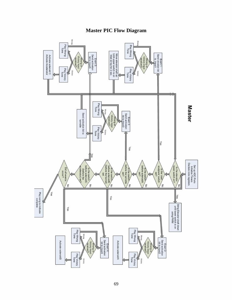
Master PIC Flow Diagram
69

Master PIC Code ;################################################# ; Robotics Academy - Kinetic Sculpture (2003-2004) ; Jason Adrian & Marc Weintraub ; Date Finalized: 4/10/04 ; ; Target PIC: 16F877A ; Program Name: MasterPIC ; Purpose: Control electronic components of sculpture ; Description: Interfaces with everything ; ;################################################# ; bit mapping: ; ***INPUTS*** ; -switches- ; B0 = elevator lower switch ; B1 = elevator upper switch ; B2 = switchA (b4 solenoidA) ; B3 = switchT (b4 turnstile) ; -event/input station bits ; B4 = switchB (b4 solenoidB) ; B5 = switchC (b4 solenoidC) ; B6 = input1 victory ; B7 = input1 wrong ; ; C0 = input2 victory ; C1 = input2 wrong ; C2 = input3 victory ; C3 = input3 wrong ; C4 = input4 victory ; C5 = input4 wrong ; C6 = input5 victory ; C7 = input5 wrong ; ; E2 = input1 start: sculpture start ; ; ***OUTPUTS*** ; A0 = input1 activate ; A1 = input2 activate ; A2 = input3 activate ; A3 = input4 activate ; A4 = not used ; A5 = supply input stations with power ; ; D0 = elevator DOWN ; D1 = elevator UP ; D2 = solenoidA ACTIVATE ; D3 = turnstile ACTIVATE ; D4 = solenoidB ACTIVATE
70
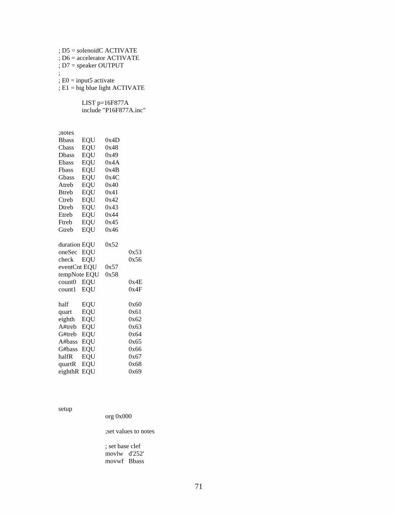
; D5 = solenoidC ACTIVATE ; D6 = accelerator ACTIVATE ; D7 = speaker OUTPUT ; ; E0 = input5 activate ; E1 = big blue light ACTIVATE LIST p=16F877A include "P16F877A.inc" ;notes Bbass EQU 0x4D Cbass EQU 0x48 Dbass EQU 0x49 Ebass EQU 0x4A Fbass EQU 0x4B Gbass EQU 0x4C Atreb EQU 0x40 Btreb EQU 0x41 Ctreb EQU 0x42 Dtreb EQU 0x43 Etreb EQU 0x44 Ftreb EQU 0x45 Gtreb EQU 0x46 duration EQU 0x52 oneSec EQU 0x53 check EQU 0x56 eventCnt EQU 0x57 tempNote EQU 0x58 count0 EQU 0x4E count1 EQU 0x4F half EQU 0x60 quart EQU 0x61 eighth EQU 0x62 A#treb EQU 0x63 G#treb EQU 0x64 A#bass EQU 0x65 G#bass EQU 0x66 halfR EQU 0x67 quartR EQU 0x68 eighthR EQU 0x69 setup org 0x000 ;set values to notes ; set base clef movlw d'252' movwf Bbass
71

movlw d'238' movwf Cbass movlw d'212' movwf Dbass movlw d'189' movwf Ebass movlw d'178' movwf Fbass movlw d'159' movwf Gbass movlw d'150' movwf G#bass ; set treble clef movlw d'141' movwf Atreb movlw d'134' movwf A#treb movlw d'126' movwf Btreb movlw d'119' movwf Ctreb movlw d'105' movwf Dtreb movlw d'94' movwf Etreb movlw d'88' movwf Ftreb movlw d'79' movwf Gtreb movlw d'75' movwf G#treb ; load one sec movlw d'121' movwf oneSec movlw d'61' movwf half movlw d'31' movwf quart movlw d'16' movwf eighth movlw d'69' movwf halfR movlw d'39' movwf quartR movlw d'24' movwf eighthR ; set IO ports bsf STATUS,RP0 ;bank 1 bcf STATUS,RP1 ; input ports
72

movlw 0xFF movwf TRISB ;portb inputs movwf TRISC ;portc inputs bsf TRISE,2 ; output ports clrf TRISA ;porta clrf TRISD ;portd bcf TRISE,0 bcf TRISE,1 ; disable a2d channels movlw 0x07 movwf ADCON1 ; set timer0 movlw 0x84 movwf OPTION_REG bcf STATUS,RP0 ;bank 0 ; set timer2 movlw 0x05 movwf T2CON ; main function main ; set initial output conditions bcf PORTE,1 clrf PORTA movlw 0x03 movwf PORTD clrf eventCnt clrf check movlw d'30' movwf duration call wait ; supply power to inputStations bsf PORTA,5 ; check the inputs from the scupture to get the ball status. ; once the input is received, the program should jump to the ; appropriate state to handle the event the ball will enter ; in the sculpture checkInputs ; --sculpture inputs-- btfss PORTB,0 ; bring elevator shaft down call moveShaftDown btfsc PORTE,2 ; goto event1: start elevator goto event1
73
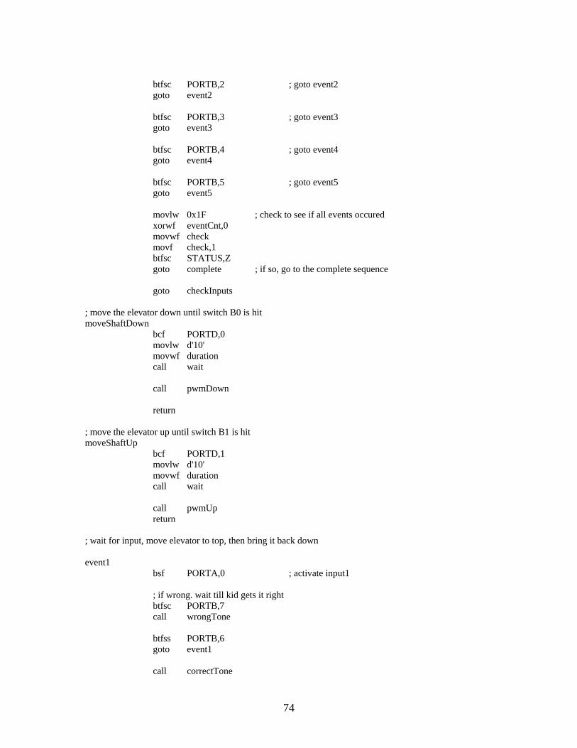
btfsc PORTB,2 ; goto event2 goto event2 btfsc PORTB,3 ; goto event3 goto event3 btfsc PORTB,4 ; goto event4 goto event4 btfsc PORTB,5 ; goto event5 goto event5 movlw 0x1F ; check to see if all events occured xorwf eventCnt,0 movwf check movf check,1 btfsc STATUS,Z goto complete ; if so, go to the complete sequence goto checkInputs ; move the elevator down until switch B0 is hit moveShaftDown bcf PORTD,0 movlw d'10' movwf duration call wait call pwmDown return ; move the elevator up until switch B1 is hit moveShaftUp bcf PORTD,1 movlw d'10' movwf duration call wait call pwmUp return ; wait for input, move elevator to top, then bring it back down event1 bsf PORTA,0 ; activate input1 ; if wrong. wait till kid gets it right btfsc PORTB,7 call wrongTone btfss PORTB,6 goto event1 call correctTone
74

call moveShaftUp movf oneSec,0 movwf duration call wait movf oneSec,0 movwf duration call wait call moveShaftDown bcf PORTA,0 ; deactivate input1 bsf eventCnt,0 ; set event checker movf oneSec,0 movwf duration call wait goto checkInputs ; wait for input, activate solenoidA event2 bsf PORTA,1 ; activate input2 btfsc PORTC,1 call wrongTone btfss PORTC,0 goto event2 call correctTone bsf PORTD,2 ; turn on solenoidA movf oneSec,0 movwf duration call wait movf oneSec,0 movwf duration call wait bcf PORTD,2 ; turn on solenoidA bcf PORTA,1 ; deactivate input2 bsf eventCnt,1 ; set event checker movf oneSec,0 movwf duration call wait goto checkInputs ; wait for input, activate turnstile event3 bsf PORTA,2 ; activate input3 btfsc PORTC,3 call wrongTone
75

btfss PORTC,2 goto event3 call correctTone bsf PORTD,3 ; activate turnstile movf oneSec,0 movwf duration call wait bcf PORTD,3 ; shut off turnstile bcf PORTA,2 ; deactivate input3 bsf eventCnt,2 ; set event checker movf oneSec,0 movwf duration call wait goto checkInputs ; wait for input, activate solenoidB event4 bsf PORTA,3 ; activate input4 btfsc PORTC,5 call wrongTone btfss PORTC,4 goto event4 call correctTone bsf PORTD,4 ; turn on solenoidB movf oneSec,0 movwf duration call wait movf oneSec,0 movwf duration call wait bcf PORTD,4 ; turn off solenoidB bcf PORTA,3 ; deactivate input4 bsf eventCnt,3 ; set event checker movf oneSec,0 movwf duration call wait goto checkInputs ; wait for input, activate solenoidC event5 bsf PORTE,0 ; activate input5 btfsc PORTC,7 call wrongTone
76
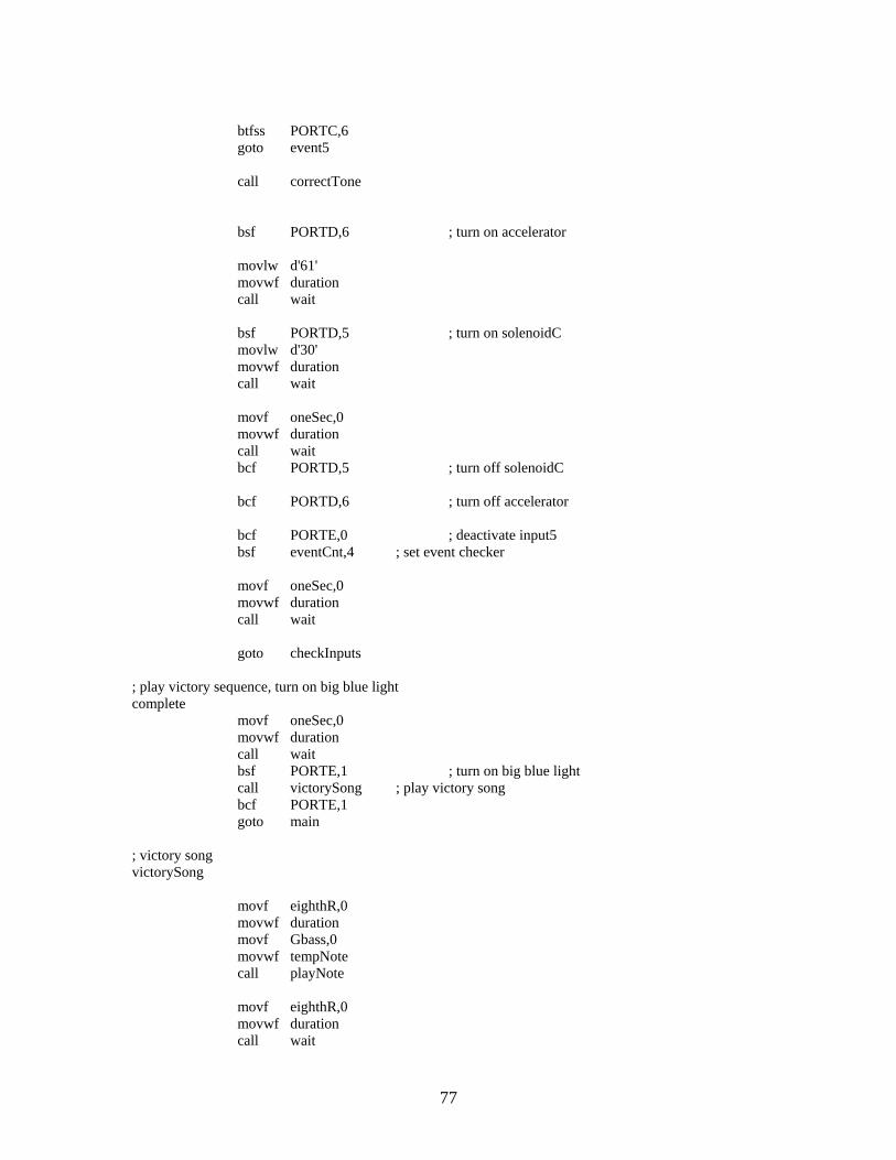
btfss PORTC,6 goto event5 call correctTone bsf PORTD,6 ; turn on accelerator movlw d'61' movwf duration call wait bsf PORTD,5 ; turn on solenoidC movlw d'30' movwf duration call wait movf oneSec,0 movwf duration call wait bcf PORTD,5 ; turn off solenoidC bcf PORTD,6 ; turn off accelerator bcf PORTE,0 ; deactivate input5 bsf eventCnt,4 ; set event checker movf oneSec,0 movwf duration call wait goto checkInputs ; play victory sequence, turn on big blue light complete movf oneSec,0 movwf duration call wait bsf PORTE,1 ; turn on big blue light call victorySong ; play victory song bcf PORTE,1 goto main ; victory song victorySong movf eighthR,0 movwf duration movf Gbass,0 movwf tempNote call playNote movf eighthR,0 movwf duration call wait
77

movf eighthR,0 movwf duration movf Gbass,0 movwf tempNote call playNote movf eighthR,0 movwf duration call wait movf eighthR,0 movwf duration movf Ebass,0 movwf tempNote call playNote movlw d'8' movwf duration call wait movf eighth,0 movwf duration movf Gbass,0 movwf tempNote call playNote movf eighthR,0 movwf duration call wait movf eighth,0 movwf duration movf Ebass,0 movwf tempNote call playNote movlw d'8' movwf duration call wait movf eighth,0 movwf duration movf Gbass,0 movwf tempNote call playNote movlw d'8' movwf duration call wait movf eighth,0 movwf duration movf Ebass,0 movwf tempNote call playNote
78
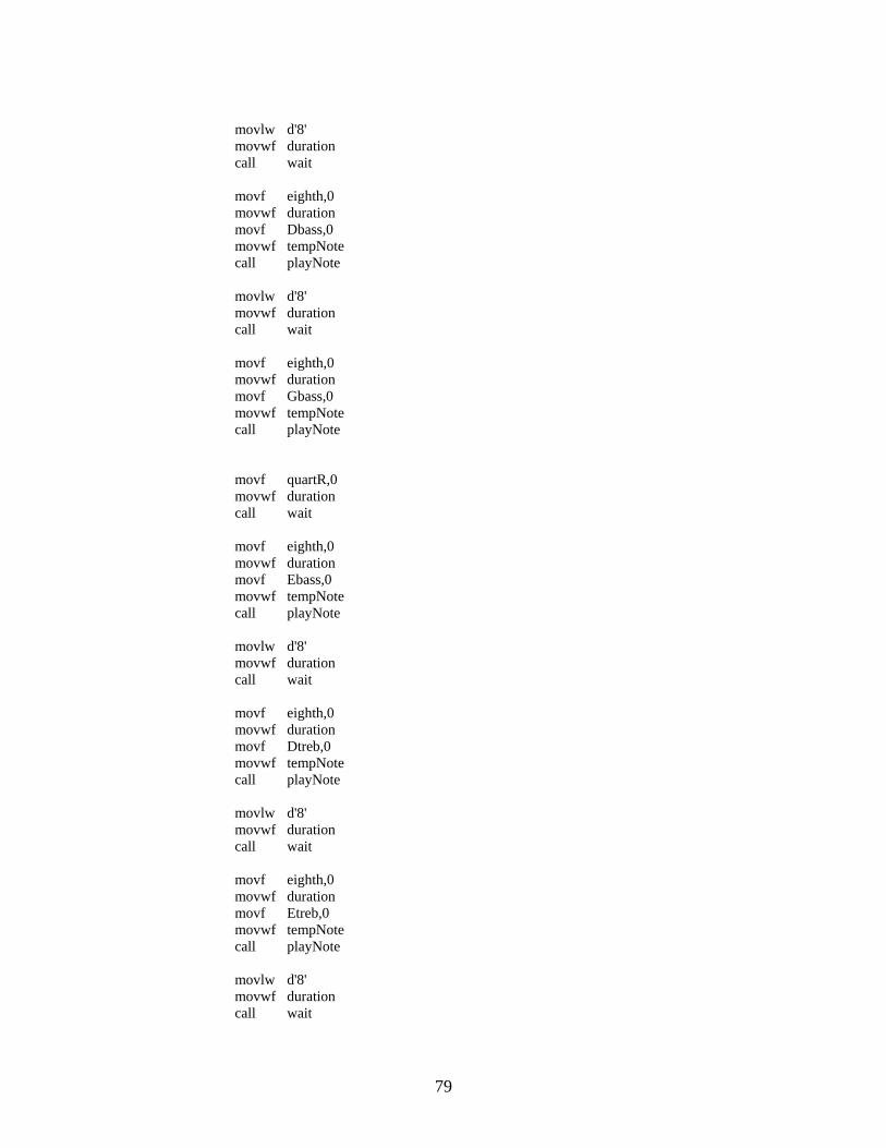
movlw d'8' movwf duration call wait movf eighth,0 movwf duration movf Dbass,0 movwf tempNote call playNote movlw d'8' movwf duration call wait movf eighth,0 movwf duration movf Gbass,0 movwf tempNote call playNote movf quartR,0 movwf duration call wait movf eighth,0 movwf duration movf Ebass,0 movwf tempNote call playNote movlw d'8' movwf duration call wait movf eighth,0 movwf duration movf Dtreb,0 movwf tempNote call playNote movlw d'8' movwf duration call wait movf eighth,0 movwf duration movf Etreb,0 movwf tempNote call playNote movlw d'8' movwf duration call wait
79

movf eighth,0 movwf duration movf Dtreb,0 movwf tempNote call playNote movlw d'8' movwf duration call wait movf eighth,0 movwf duration movf Etreb,0 movwf tempNote call playNote movlw d'8' movwf duration call wait movf eighth,0 movwf duration movf Dtreb,0 movwf tempNote call playNote movlw d'16' movwf duration call wait movlw d'10' movwf duration movf Gbass,0 movwf tempNote call playNote movlw d'2' movwf duration call wait movlw d'10' movwf duration movf Btreb,0 movwf tempNote call playNote movlw d'2' movwf duration call wait movlw d'10' movwf duration movf Atreb,0 movwf tempNote call playNote
80

movlw d'4' movwf duration call wait movf oneSec,0 movwf duration movf Gbass,0 movwf tempNote call playNote movlw d'4' movwf duration call wait movlw d'4' movwf duration movf Gbass,0 movwf tempNote call playNote movlw d'4' movwf duration movf Atreb,0 movwf tempNote call playNote movlw d'4' movwf duration movf Btreb,0 movwf tempNote call playNote movlw d'4' movwf duration movf Ctreb,0 movwf tempNote call playNote movlw d'4' movwf duration movf Dtreb,0 movwf tempNote call playNote movlw d'4' movwf duration movf Etreb,0 movwf tempNote call playNote movlw d'4' movwf duration movf Ftreb,0 movwf tempNote call playNote
81

movlw d'161' movwf duration movf Gtreb,0 movwf tempNote call playNote return ; tone for correct input correctTone movf eighthR,0 movwf duration movf Btreb,0 movwf tempNote call playNote movf half,0 movwf duration movf Gbass,0 movwf tempNote call playNote return ; tone for wrong input wrongTone movf eighthR,0 movwf duration movf Bbass,0 movwf tempNote call playNote movlw d'8' movwf duration call wait movf oneSec,0 movwf duration movf Bbass,0 movwf tempNote call playNote movlw d'161' movwf duration call wait return playNote ; produce square wave of certain frequency movf tempNote,0 bsf STATUS,RP0 movwf PR2 bcf STATUS,RP0 bsf PORTD,7 bcf INTCON,TMR0IF ; clear interrupt bit out0 ; check interupt flags btfss PIR1,TMR2IF
82

goto out0 bcf PIR1,TMR2IF bcf PORTD,7 out1 ; check interupt flags btfss PIR1,TMR2IF goto out1 bcf PIR1,TMR2IF bsf PORTD,7 btfss INTCON,TMR0IF ; skip if interrupt is not enabled goto out0 bcf INTCON,TMR0IF ; clear interrupt bit decfsz duration goto out0 return pwmUp ; 75% duty cycle square wave at 2KHz movlw d'31' bsf STATUS,RP0 movwf PR2 bcf STATUS,RP0 bsf PORTD,1 out0u0 ; check interupt flags btfss PIR1,TMR2IF goto out0u0 bcf PIR1,TMR2IF bcf PORTD,1 out1u0 ; check interupt flags btfss PIR1,TMR2IF goto out1u0 out1u1 ; check interupt flags btfss PIR1,TMR2IF goto out1u1 bcf PIR1,TMR2IF out1u2 ; check interupt flags btfss PIR1,TMR2IF goto out1u2 bcf PIR1,TMR2IF bsf PORTD,1 btfss PORTB,1 ; skip if switch is not pressed goto out0u0 return pwmDown ; 50 % duty cycle square wave at 2KHz movlw d'63' bsf STATUS,RP0 movwf PR2
83

bcf STATUS,RP0 bsf PORTD,0 out0d ; check interupt flags btfss PIR1,TMR2IF goto out0d bcf PIR1,TMR2IF bcf PORTD,0 out1d ; check interupt flags btfss PIR1,TMR2IF goto out1d bcf PIR1,TMR2IF bsf PORTD,0 btfss PORTB,0 ; skip if switch is not pressed goto out0d return ; wait for a given duration of time wait ; produce square wave of certain frequency bcf STATUS,RP0 bcf INTCON,TMR0IF ; clear interrupt bit wait4int btfss INTCON,TMR0IF ; skip if interrupt is not enabled goto wait4int bcf INTCON,TMR0IF ; clear interrupt bit decfsz duration goto wait4int return endz end
84

Simon Flow Diagram
85

Simon Code
;################################################# ; Robotics Academy - Kinetic Sculpture (2003-2004) ; Jason Adrian & Marc Weintraub ; Date Finalized: 4/10/04 ; ; Target PIC: 16F84A ; Program Name: Simon ; Purpose: Input device ; Description: Simon game. A pattern of 4 lights ; are displayed, which need to be matched to win. ; ;################################################# LIST p=16F84A include "P16F84a.inc" _CONFIG_0x3d18 org 0x000 DATAONE EQU 0x16 DATATWO EQU 0x17 DATATHREE EQU 0x18 DATAFOUR EQU 0x19 INPUT EQU 0x1c clock EQU 0x1d count EQU 0x21 select EQU 0x22 decoded EQU 0x23 waitCnt EQU 0x24 win EQU 0x25 PREVINPUT EQU 0x26 ;SET UP INPUT and OUTPUT PORTS bsf STATUS, RP0 ;go to bank b ; set A to input movlw 0x0F movwf TRISA ; set B to input and output movlw 0x30 movwf TRISB ; enable timer movlw 0x81 movwf OPTION_REG bcf STATUS, RP0 ;go to bank a clrf PORTB
86
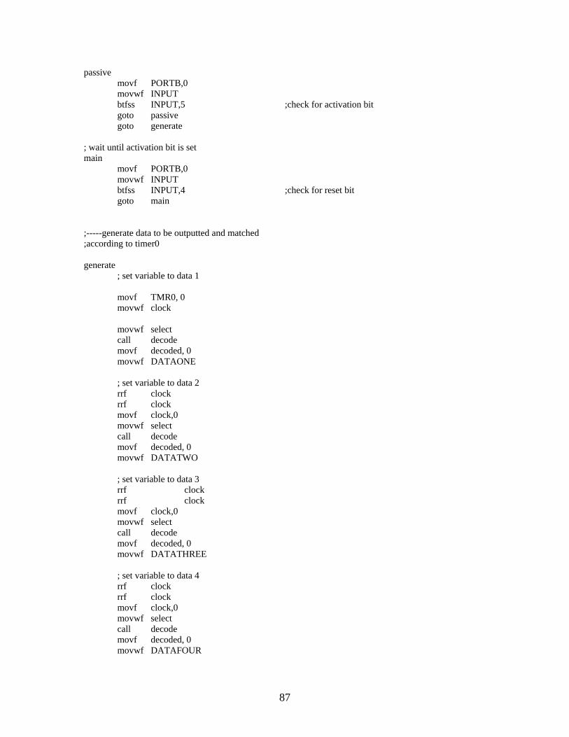
passive movf PORTB,0 movwf INPUT btfss INPUT,5 ;check for activation bit goto passive goto generate ; wait until activation bit is set main movf PORTB,0 movwf INPUT btfss INPUT,4 ;check for reset bit goto main ;-----generate data to be outputted and matched ;according to timer0 generate ; set variable to data 1 movf TMR0, 0 movwf clock movwf select call decode movf decoded, 0 movwf DATAONE ; set variable to data 2 rrf clock rrf clock movf clock,0 movwf select call decode movf decoded, 0 movwf DATATWO ; set variable to data 3 rrf clock rrf clock movf clock,0 movwf select call decode movf decoded, 0 movwf DATATHREE ; set variable to data 4 rrf clock rrf clock movf clock,0 movwf select call decode movf decoded, 0 movwf DATAFOUR
87

;-----display the pattern onto the buttons displayPattern call wait movf DATAONE, 0 movwf PORTB call wait clrf PORTB call wait movf DATATWO, 0 movwf PORTB call wait clrf PORTB call wait movf DATATHREE, 0 movwf PORTB call wait clrf PORTB call wait movf DATAFOUR, 0 movwf PORTB call wait clrf PORTB ; check input to see if it matches DATAONE inputcheck1 movf PORTA, 0 movwf INPUT xorwf DATAONE,1 btfsc STATUS, Z goto inputcheck2 movf INPUT, 1 btfss STATUS, Z goto gameover goto inputcheck1 ; do not do anything as long as button is pressed inputcheck2 call wait2 movf INPUT,0 movwf PREVINPUT movwf PORTB movf PORTA, 0 movwf INPUT xorwf PREVINPUT,1 btfsc STATUS, Z goto inputcheck2 clrf PORTB
88

;check input to see if it matches DATATWO inputcheck2a movf PORTA, 0 movwf INPUT xorwf DATATWO,1 btfsc STATUS, Z goto inputcheck3 movf INPUT, 1 btfss STATUS, Z goto gameover goto inputcheck2a ; do not do anything as long as button is pressed inputcheck3 call wait2 movf INPUT,0 movwf PREVINPUT movwf PORTB movf PORTA, 0 movwf INPUT xorwf PREVINPUT,1 btfsc STATUS, Z goto inputcheck3 clrf PORTB ; check input to see if it matches DATATHREE inputcheck3a movf PORTA, 0 movwf INPUT xorwf DATATHREE,1 btfsc STATUS, Z goto inputcheck4 movf INPUT, 1 btfss STATUS, Z goto gameover goto inputcheck3a ; do not do anything as long as button is pressed inputcheck4 call wait2 movf INPUT,0 movwf PREVINPUT movwf PORTB movf PORTA, 0 movwf INPUT xorwf PREVINPUT,1 btfsc STATUS, Z goto inputcheck4 clrf PORTB
89

; check input to see if it matches DATAFOUR inputcheck movf PORTA, 0 movwf INPUT xorwf DATAFOUR,1 btfsc STATUS, Z goto victory movf INPUT, 1 btfss STATUS, Z goto gameover goto inputcheck4a gameover movlw 0x40 ;bit 6 indicates failure movwf PORTB call wait call wait clrf PORTB goto main victory ; do not do anything as long as button is pressed inputchecklast call waitC movf INPUT,0 movwf PREVINPUT movwf PORTB movf PORTA, 0 movwf INPUT xorwf PREVINPUT,1 btfsc STATUS, Z goto inputchecklast clrf PORTB call wait2 call wait2 movlw 0x03 movwf win ;-----display a pattern on the buttons to indicate victory winPattern movlw 0x01 movwf PORTB call wait2 movlw 0x02 movwf PORTB call wait2
90

movlw 0x08 movwf PORTB call wait2 movlw 0x04 movwf PORTB call wait2 decfsz win,1 goto winPattern ;activate victory bit clrf PORTB bsf PORTB, 7 call wait call wait clrf PORTB goto main ;-----decoder function. 2-4 bit decoder decode clrf decoded btfsc select, 1 goto MSB1 goto MSB0 MSB1 btfsc select, 0 bsf decoded, 3 btfss select, 0 bsf decoded, 2 return MSB0 btfsc select, 0 bsf decoded, 1 btfss select, 0 bsf decoded, 0 return ;-----delay generator wait movlw 0xFF ; load count1 with decimal 100 movwf waitCnt d1a movlw 0xFF ; load count2 with decimal 100 movwf count d2a NOP NOP NOP NOP decfsz count,1 goto d2a decfsz waitCnt,1 goto d1a return
91
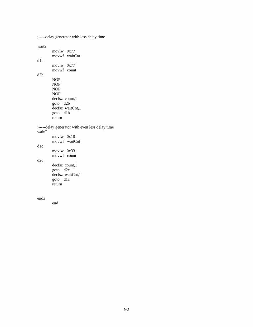
;-----delay generator with less delay time wait2 movlw 0x77 movwf waitCnt d1b movlw 0x77 movwf count d2b NOP NOP NOP NOP decfsz count,1 goto d2b decfsz waitCnt,1 goto d1b return ;-----delay generator with even less delay time waitC movlw 0x10 movwf waitCnt d1c movlw 0x33 movwf count d2c decfsz count,1 goto d2c decfsz waitCnt,1 goto d1c return endz end
92
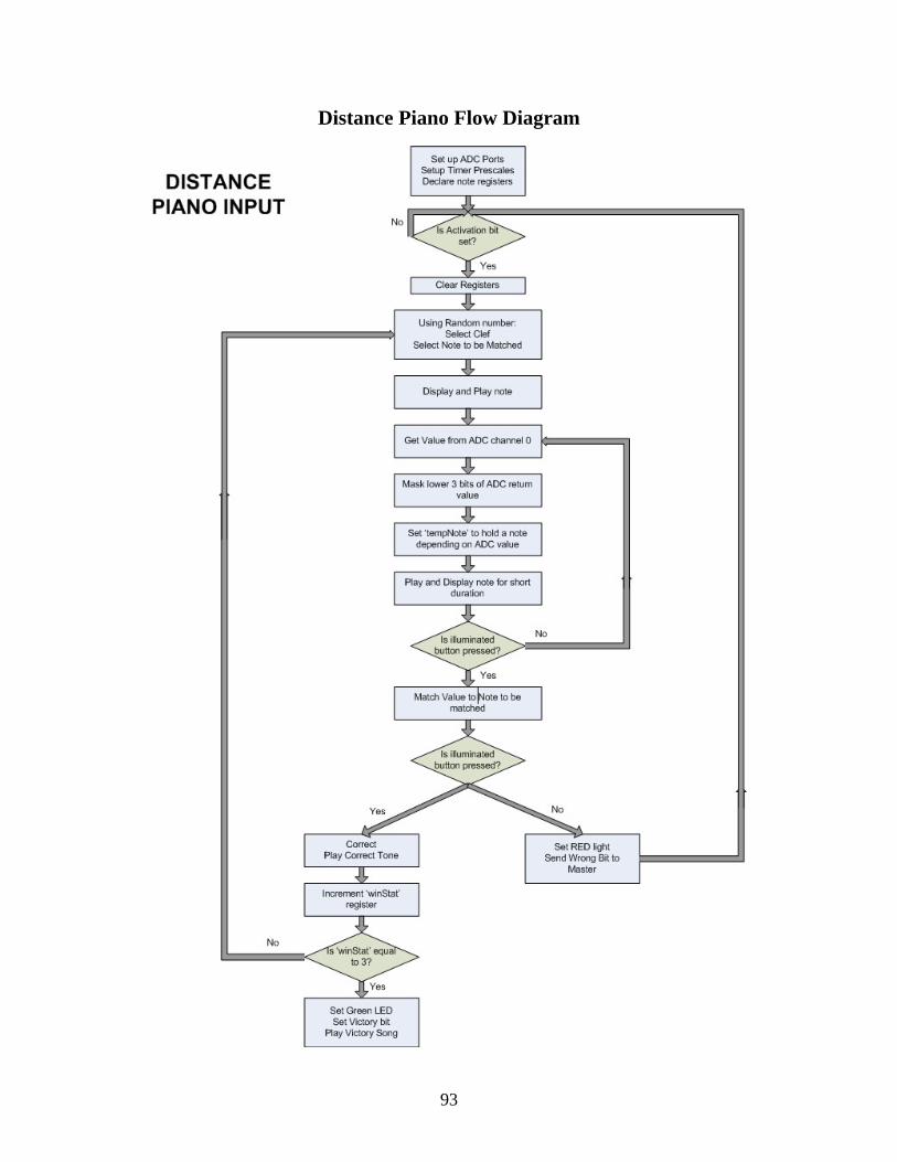
Distance Piano Flow Diagram
93
Distance Piano Code
;################################################# ; Robotics Academy - Kinetic Sculpture (2003-2004) ; Jason Adrian & Marc Weintraub ; Date Finalized: 4/10/04 ; ; Target PIC: 16F877A ; Program Name: Distance Piano ; Purpose: Input device ; Description: A game where the player must match ; a given note by putting their hand a certain ; distance away from the sensor. There will be three ; three notes. ; ;################################################# ; PORTB & 4msb of PORTD are outputs to the notes. ; C7-C5 are count outputs ; C4 is square wave output ; D3, D2 are Victory and Wrong outputs respectively ; A0 is Analog input ; A1 is Digital input ; A2 is activation bit LIST p=16F877A include "P16F877A.inc" ;notes ;declare registers clock EQU 0x21 select EQU 0x22 decoded EQU 0x23 Atreb EQU 0x40 Btreb EQU 0x41 Ctreb EQU 0x42 Dtreb EQU 0x43 Etreb EQU 0x44 Ftreb EQU 0x45 Gtreb EQU 0x46 adVal EQU 0x47 Bbass EQU 0x39 Cbass EQU 0x48 Dbass EQU 0x49 Ebass EQU 0x4A Fbass EQU 0x4B Gbass EQU 0x4C
94
tempNote EQU 0x4D count0 EQU 0x4E count1 EQU 0x4F count EQU 0x50 waitCnt EQU 0x51 duration EQU 0x52 oneSec EQU 0x53 noteReg EQU 0x54 winStat EQU 0x55 check EQU 0x56 setLight EQU 0x57 toggle EQU 0x58 half EQU 0x60 quart EQU 0x61 eighth EQU 0x62 A#treb EQU 0x63 G#treb EQU 0x64 A#bass EQU 0x65 G#bass EQU 0x66 halfR EQU 0x67 quartR EQU 0x68 eighthR EQU 0x69 thisNote EQU 0x6A lightReg EQU 0x6B setup org 0x000 ; clrf winStat ; goto checkInput ;set values to notes ; set base clef movlw d'268' movwf A#bass movlw d'252' movwf Bbass movlw d'238' movwf Cbass movlw d'212' movwf Dbass movlw d'189' movwf Ebass movlw d'178' movwf Fbass movlw d'159' movwf Gbass movlw d'150' movwf G#bass ; set treble clef movlw d'141'
95
movwf Atreb movlw d'134' movwf A#treb movlw d'126' movwf Btreb movlw d'119' movwf Ctreb movlw d'105' movwf Dtreb movlw d'94' movwf Etreb movlw d'88' movwf Ftreb movlw d'79' movwf Gtreb movlw d'75' movwf G#treb ; load one sec movlw d'121' movwf oneSec movlw d'61' movwf half movlw d'31' movwf quart movlw d'16' movwf eighth movlw d'69' movwf halfR movlw d'39' movwf quartR movlw d'24' movwf eighthR ; set IO ports bsf STATUS,RP0 ;bank 1 bcf STATUS,RP1 movlw 0x07 movwf TRISA ;2 inputs on porta clrf TRISB ;portb outputs clrf TRISC ;portc outputs clrf TRISD ;portd outputs ; set timer2, timer0 and a2d movlw 0x4E movwf ADCON1 movlw 0x84 movwf OPTION_REG bcf STATUS,RP0 ;bank 0 movlw 0x41 ;Fosc/4 A/D ch0 movwf ADCON0 movlw 0x05 movwf T2CON
96

;main function. clear all ports and enter passive state main clrf PORTB ; output LED to notes clrf PORTC ; C0 = 9th note, C1,C2 = treble, bass ; C5,C6,C7 = win status clrf PORTD clrf winStat clrf noteReg clrf toggle ;nothing should happen until the game is activated passive btfss PORTA,2 ;check for activation bit goto passive ;generate a value according to the time ;the current time would determine which note ;and whether the note is base or treble generate movlw 0xE0 andwf PORTC,1 movf TMR2, 0 movwf clock movwf select call decode movf decoded, 0 btfsc clock, 3 call shiftThree movf decoded,0 movwf noteReg ; treble or base btfsc clock, 4 bsf PORTC,1 btfss clock, 4 bsf PORTC,2 ;display the note on the LEDs and play the note, ;on the speaker ;this tells the player which note he/she should match displayAndPlay btfsc PORTC,1 call setTreb movf noteReg,0 movwf setLight movwf lightReg btfsc PORTC,1 call getNoteTreb btfsc PORTC,2 call getNoteBass
97
movlw d'255' movwf duration movf noteReg,0 movwf tempNote call playNote clrf PORTB bcf PORTC,0 clrf thisNote goto pianoState pianoState bcf PORTA,3 call a2d ; do a2d movlw 0xF8 ; mask bits andwf adVal ; least significant 3 bits become zero movlw 0x05 movwf duration ; if ye high play ye note ; set the light movlw 0x40 btfss toggle,0 movlw 0x00 movwf setLight ; set the note movf Atreb,0 btfss toggle,0 movf Gtreb,0 movwf tempNote movlw 0x88 xorwf adVal,0 movwf check btfsc STATUS, Z call playNote ; if ye high play ye note movlw 0x40 btfss toggle,0 movlw 0x00 movwf setLight movf Atreb,0 btfss toggle,0 movf Gtreb,0 movwf tempNote movlw 0x80 xorwf adVal,0 movwf check btfsc STATUS, Z call playNote
98

; if ye high play ye note movlw 0x40 btfss toggle,0 movlw 0x00 movwf setLight movf Atreb,0 btfss toggle,0 movf Gtreb,0 movwf tempNote movlw 0x78 xorwf adVal,0 movwf check btfsc STATUS, Z call playNote ; if ye high play ye note movlw 0x20 btfss toggle,0 movlw 0x80 movwf setLight movf Gbass,0 btfss toggle,0 movf Ftreb,0 movwf tempNote movlw 0x70 xorwf adVal,0 movwf check btfsc STATUS, Z call playNote ; if ye high play ye note movlw 0x20 btfss toggle,0 movlw 0x80 movwf setLight movf Gbass,0 btfss toggle,0 movf Ftreb,0 movwf tempNote movlw 0x68 xorwf adVal,0 movwf check btfsc STATUS, Z call playNote ; if ye high play ye note movlw 0x20 btfss toggle,0 movlw 0x80 movwf setLight movf Gbass,0 btfss toggle,0 movf Ftreb,0 movwf tempNote
99
movlw 0x60 xorwf adVal,0 movwf check btfsc STATUS, Z call playNote ; if ye high play ye note movlw 0x10 btfss toggle,0 movlw 0x40 movwf setLight movf Fbass,0 btfss toggle,0 movf Etreb,0 movwf tempNote movlw 0x58 xorwf adVal,0 movwf check btfsc STATUS, Z call playNote ; if ye high play ye note movlw 0x10 btfss toggle,0 movlw 0x40 movwf setLight movf Fbass,0 btfss toggle,0 movf Etreb,0 movwf tempNote movlw 0x50 xorwf adVal,0 movwf check btfsc STATUS, Z call playNote ; if ye high play ye note movlw 0x08 btfss toggle,0 movlw 0x20 movwf setLight movf Ebass,0 btfss toggle,0 movf Dtreb,0 movwf tempNote movlw 0x48 xorwf adVal,0 movwf check btfsc STATUS, Z call playNote ; if ye high play ye note movlw 0x08
100

btfss toggle,0 movlw 0x20 movwf setLight movf Ebass,0 btfss toggle,0 movf Dtreb,0 movwf tempNote movlw 0x40 xorwf adVal,0 movwf check btfsc STATUS, Z call playNote ; if ye high play ye note movlw 0x04 btfss toggle,0 movlw 0x10 movwf setLight movf Dbass,0 btfss toggle,0 movf Ctreb,0 movwf tempNote movlw 0x38 xorwf adVal,0 movwf check btfsc STATUS, Z call playNote ; if ye high play ye note movlw 0x02 btfss toggle,0 movlw 0x08 movwf setLight movf Cbass,0 btfss toggle,0 movf Btreb,0 movwf tempNote movlw 0x30 xorwf adVal,0 movwf check btfsc STATUS, Z call playNote ; if ye high play ye note movlw 0x01 btfss toggle,0 movlw 0x04 movwf setLight movf Bbass,0 btfss toggle,0 movf Atreb,0 movwf tempNote movlw 0x28 xorwf adVal,0 movwf check btfsc STATUS, Z
101

call playNote ; if ye high play ye note movlw 0x01 btfss toggle,0 movlw 0x04 movwf setLight movf Bbass,0 btfss toggle,0 movf Atreb,0 movwf tempNote movlw 0x20 xorwf adVal,0 movwf check btfsc STATUS, Z call playNote clrf PORTB btfsc PORTA,1 goto checkInput goto pianoState checkInput bsf PORTA,3 movf thisNote,0 xorwf noteReg,0 movwf check btfss STATUS,Z goto wrong call oneWin incf winStat,1 movlw 0x01 xorwf winStat,0 movwf check btfsc STATUS, Z bsf PORTC,5 movlw 0x02 xorwf winStat,0 movwf check btfsc STATUS, Z bsf PORTC,6 movlw 0x03 xorwf winStat,0 movwf check btfsc STATUS, Z goto victory clrf PORTB clrf noteReg clrf lightReg
102

movlw d'121' movwf duration call rest goto generate oneWin bsf PORTC,3 movlw d'8' movwf duration call rest movlw d'8' movwf duration movf Gbass,0 movwf tempNote call playNote movlw d'8' movwf duration movf Atreb,0 movwf tempNote call playNote movlw d'8' movwf duration movf Btreb,0 movwf tempNote call playNote movlw d'8' movwf duration movf Ctreb,0 movwf tempNote call playNote movlw d'8' movwf duration movf Dtreb,0 movwf tempNote call playNote movlw d'8' movwf duration movf Etreb,0 movwf tempNote call playNote movlw d'8' movwf duration movf Ftreb,0 movwf tempNote call playNote movlw d'8'
103
movwf duration movf Gtreb,0 movwf tempNote call playNote bcf PORTA,3 movlw d'31' movwf duration call rest bcf PORTC,3 return wrong movlw d'20' movwf duration call rest bcf PORTA,3 bsf PORTD,2 movlw d'121' movwf duration call rest bcf PORTD,2 movf lightReg,0 movwf noteReg goto displayAndPlay victory bcf PORTA,3 movlw d'10' movwf duration call rest bcf PORTA,3 bsf PORTC,7 movf eighth,0 movwf duration movf Ctreb,0 movwf tempNote call playNote movlw d'8' movwf duration call rest movf eighth,0 movwf duration movf Ctreb,0 movwf tempNote call playNote movlw d'8' movwf duration
104

call rest movf eighth,0 movwf duration movf Ctreb,0 movwf tempNote call playNote movlw d'8' movwf duration call rest movf quart,0 movwf duration movf Ctreb,0 movwf tempNote call playNote movf eighthR,0 movwf duration call rest movf quart,0 movwf duration movf G#bass,0 movwf tempNote call playNote movf eighthR,0 movwf duration call rest movf quart,0 movwf duration movf A#treb,0 movwf tempNote call playNote movf eighthR,0 movwf duration call rest movf eighth,0 movwf duration movf Ctreb,0 movwf tempNote call playNote movf eighthR,0 movwf duration call rest movf eighth,0 movwf duration movf A#treb,0 movwf tempNote
105

call playNote movf half,0 movwf duration movf Ctreb,0 movwf tempNote call playNote bsf PORTD,3 movlw d'121' movwf duration bcf PORTD,3 call rest clrf PORTB clrf PORTC goto passive ;function to set the notes to the appropriate value ;if treble is selected in the generate function, ;the treble scale will be loaded getNoteTreb btfsc noteReg,2 movf Atreb,0 btfsc noteReg,3 movf Btreb,0 btfsc noteReg,4 movf Ctreb,0 btfsc noteReg,5 movf Dtreb,0 btfsc noteReg,6 movf Etreb,0 btfsc noteReg,7 movf Ftreb,0 movf noteReg,1 btfsc STATUS,Z movf Gtreb,0 movwf noteReg bcf toggle,0 return ;same for bass getNoteBass btfsc noteReg,0 movf Bbass,0 btfsc noteReg,1 movf Cbass,0 btfsc noteReg,2 movf Dbass,0 btfsc noteReg,3 movf Ebass,0 btfsc noteReg,4 movf Fbass,0 btfsc noteReg,5 movf Gbass,0
106
btfsc noteReg,6 movf Atreb,0 movwf noteReg bsf toggle,0 return ;function to set the note to treble. ;this is needed for the LED lights setTreb btfsc noteReg,6 clrf noteReg rlf noteReg,1 rlf noteReg,1 return ;function to shift the decoded register 3 bits shiftThree bcf STATUS,C rlf decoded,1 rlf decoded,1 rlf decoded,1 return ;function to decode timer register. This takes a binary 2 bit value and decodes ;it to 4 bits. decode clrf decoded btfsc select, 1 goto MSB1 goto MSB0 MSB1 btfsc select, 0 bsf decoded, 3 btfss select, 0 bsf decoded, 2 return MSB0 btfsc select, 0 bsf decoded, 1 btfss select, 0 bsf decoded, 0 return ;rest function. produces a delay of a certain amount of time rest ; delay bcf STATUS,RP0 bcf INTCON,TMR0IF ; clear interrupt bit wait4int btfss INTCON,TMR0IF ; skip if interrupt is not enabled goto wait4int bcf INTCON,TMR0IF ; clear interrupt bit decfsz duration goto wait4int return
107
;play note function. plays the given note playNote ; produce square wave of certain frequency movf setLight,1 btfsc STATUS,Z bsf PORTC,0 btfss STATUS,Z bcf PORTC,0 movf setLight,0 movwf PORTB movf tempNote,0 movwf thisNote bsf STATUS,RP0 movwf PR2 bcf STATUS,RP0 bsf PORTC,4 bcf INTCON,TMR0IF ; clear interrupt bit ;output 0 out0 ; check interupt flags btfss PIR1,TMR2IF goto out0 bcf PIR1,TMR2IF bcf PORTC,4 ;output 1 out1 ; check interupt flags btfss PIR1,TMR2IF goto out1 bcf PIR1,TMR2IF bsf PORTC,4 btfss INTCON,TMR0IF ; skip if interrupt is not enabled goto out0 bcf INTCON,TMR0IF ; clear interrupt bit decfsz duration goto out0 clrf PORTB bcf PORTC,0 return ;analog to digital conversion a2d bsf ADCON0,GO newConv btfsc ADCON0,GO ;Wait for conversion to complete goto newConv movf ADRESH,W ; set adVal to 8 MSB of 10bit AD conversion movwf adVal return endz end
108
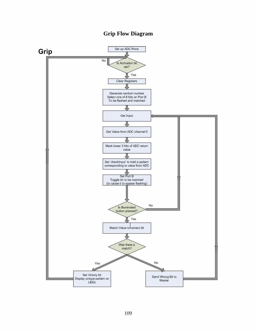
Grip Flow Diagram
109

Grip Code ;################################################# ; Robotics Academy - Kinetic Sculpture (2003-2004) ; Jason Adrian & Marc Weintraub ; Date Finalized: 4/10/04 ; ; Target PIC: 16F88 ; Program Name: Grip ; Purpose: Input device ; Description: The player is to squeeze a grip device ; until a certain threshold is met ; ;################################################# LIST p=16F88 include "P16F88.inc" ;Setting ports duration EQU 0x40 rightInput EQU 0x41 adVal EQU 0x42 thisInput EQU 0x43 check EQU 0x44 toggle EQU 0x45 count EQU 0x46 rightVal EQU 0x47 checkInput EQU 0x48 compareInput EQU 0x49 org 0x000 bsf STATUS,RP0 ;bank 1 bcf STATUS,RP1 movlw 0x07 movwf TRISA clrf TRISB ;portb output movlw 0x60 movwf OSCCON clrf ADCON1 movlw 0x01 movwf ANSEL ;activate all AD channels ; set timer0 movlw 0x84 movwf OPTION_REG bcf STATUS,RP0 ;bank 0 ;initialize variables initialize clrf TMR0 clrf PORTA movlw 0x01 clrf adVal clrf PORTB movlw 0x41
110
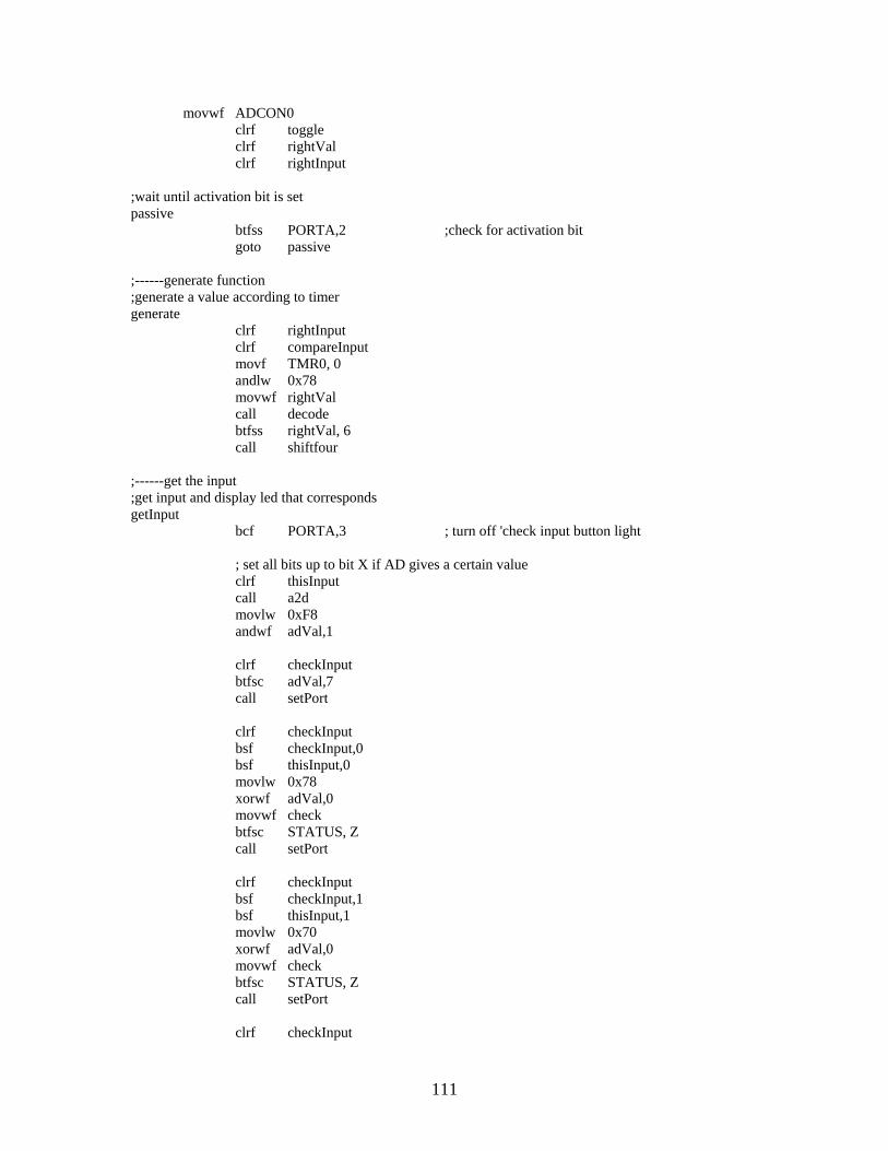
movwf ADCON0 clrf toggle clrf rightVal clrf rightInput ;wait until activation bit is set passive btfss PORTA,2 ;check for activation bit goto passive ;------generate function ;generate a value according to timer generate clrf rightInput clrf compareInput movf TMR0, 0 andlw 0x78 movwf rightVal call decode btfss rightVal, 6 call shiftfour ;------get the input ;get input and display led that corresponds getInput bcf PORTA,3 ; turn off 'check input button light ; set all bits up to bit X if AD gives a certain value clrf thisInput call a2d movlw 0xF8 andwf adVal,1 clrf checkInput btfsc adVal,7 call setPort clrf checkInput bsf checkInput,0 bsf thisInput,0 movlw 0x78 xorwf adVal,0 movwf check btfsc STATUS, Z call setPort clrf checkInput bsf checkInput,1 bsf thisInput,1 movlw 0x70 xorwf adVal,0 movwf check btfsc STATUS, Z call setPort clrf checkInput
111
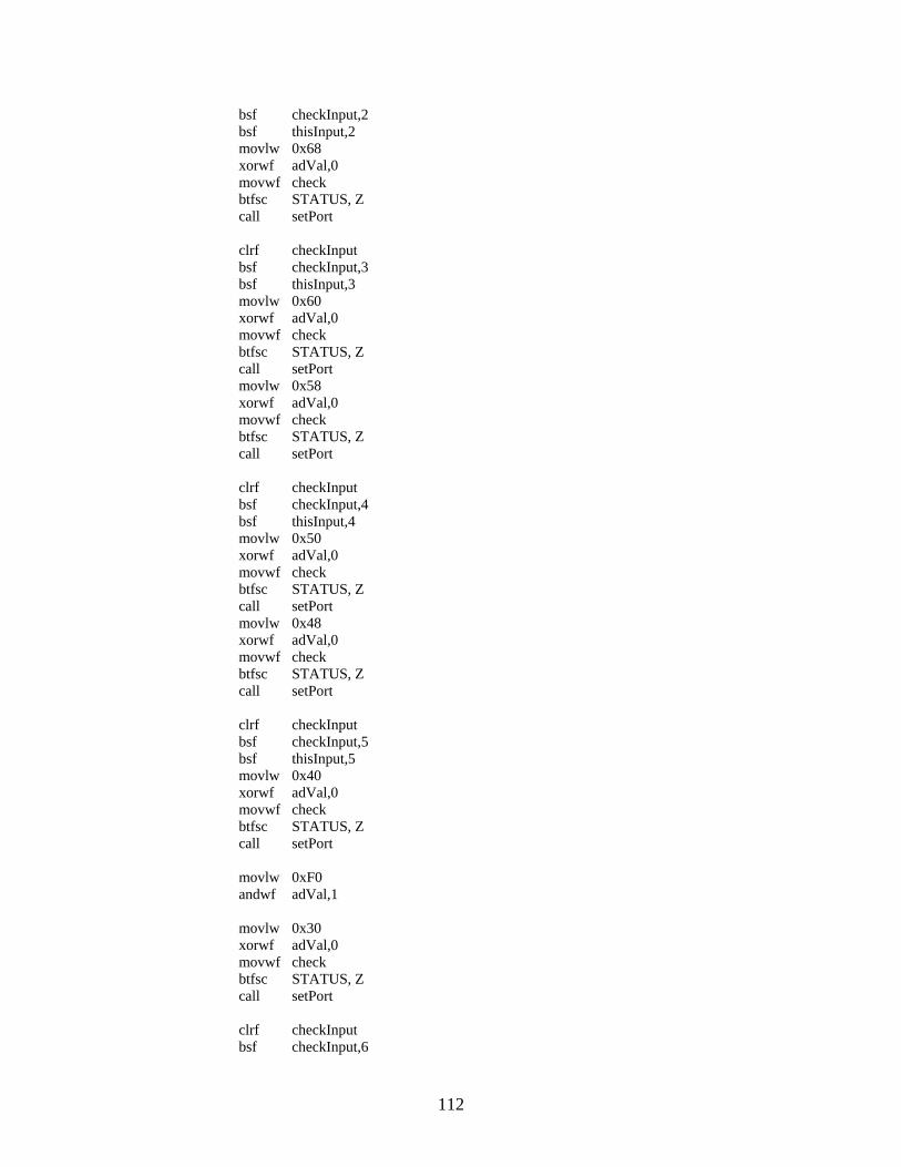
bsf checkInput,2 bsf thisInput,2 movlw 0x68 xorwf adVal,0 movwf check btfsc STATUS, Z call setPort clrf checkInput bsf checkInput,3 bsf thisInput,3 movlw 0x60 xorwf adVal,0 movwf check btfsc STATUS, Z call setPort movlw 0x58 xorwf adVal,0 movwf check btfsc STATUS, Z call setPort clrf checkInput bsf checkInput,4 bsf thisInput,4 movlw 0x50 xorwf adVal,0 movwf check btfsc STATUS, Z call setPort movlw 0x48 xorwf adVal,0 movwf check btfsc STATUS, Z call setPort clrf checkInput bsf checkInput,5 bsf thisInput,5 movlw 0x40 xorwf adVal,0 movwf check btfsc STATUS, Z call setPort movlw 0xF0 andwf adVal,1 movlw 0x30 xorwf adVal,0 movwf check btfsc STATUS, Z call setPort clrf checkInput bsf checkInput,6
112

bsf thisInput,6 movlw 0x20 xorwf adVal,0 movwf check btfsc STATUS, Z call setPort movlw 0x10 xorwf adVal,0 movwf check btfsc STATUS, Z call setPort clrf checkInput bsf checkInput,7 bsf thisInput,7 movf adVal,1 btfsc STATUS,Z call setPort btfsc PORTA,1 goto checkThis goto getInput ;-------check function ;check to see if the input is correct checkThis bsf PORTA,3 movf rightInput,0 xorwf compareInput,0 movwf check btfss STATUS, Z goto wrong call victory bsf PORTA,7 ;set Correct bit call wait call wait bcf PORTA,7 clrf PORTB goto passive ;-------victory function ;display a pattern that indicate victory victory clrf PORTB call wait0 call wait0 call wait0 bcf PORTA,3 movlw 0x10 movwf count bsf PORTB,0 loop1 call wait0 rlf PORTB,1 decfsz count
113

goto loop1 movlw 0x10 movwf count loop2 call wait0 rrf PORTB,1 decfsz count goto loop2 clrf PORTB return ;------set the LEDs connected to port ;set values to PORTB setPort movf checkInput,0 movwf compareInput movf thisInput,0 movwf PORTB btfsc toggle,0 call setBit btfss toggle,0 call resetBit movf rightInput,0 xorwf checkInput,0 movwf check btfsc STATUS, Z call setBit decfsz count,1 return comf toggle,1 movlw 0xFF movwf count return ;------set the correct LED ;show the LED needed to be matched setBit movf rightInput,0 iorwf PORTB,1 return ;------reset the correct LED ;turn the LED needed to be matched resetBit comf rightInput,0 andwf PORTB,1 return ;------analog to digital converter a2d bsf ADCON0,GO newConv btfsc ADCON0,GO ;Wait for conversion to complete
114

goto newConv movf ADRESH,W movwf adVal ; set adVal to 8 MSB of 10bit AD conversion return ;------wrong function wrong clrf PORTB bsf PORTA,6 ;set WRONG bit call wait bcf PORTA,3 call wait bcf PORTA,6 goto getInput ;------shift register 4 bits shiftfour bcf STATUS,C ; clear carry bit so register isn't affected rlf rightInput,1 rlf rightInput,1 rlf rightInput,1 rlf rightInput,1 return ;------decoder ; 2 to 4 bit decoder decode clrf rightInput btfsc rightVal, 5 goto MSB1 goto MSB0 MSB1 btfsc rightVal, 4 bsf rightInput, 0 btfss rightVal, 4 bsf rightInput, 1 return MSB0 btfsc rightVal, 5 bsf rightInput, 2 btfss rightVal, 5 bsf rightInput, 3 return ;------wait function ;wait for a fixed duration of time wait movlw d'121' movwf duration bcf INTCON,TMR0IF ; clear interrupt bit wait4int btfss INTCON,TMR0IF ; skip if interrupt is not enabled goto wait4int bcf INTCON,TMR0IF ; clear interrupt bit
115

decfsz duration goto wait4int return ;------shorter wait ;wait for a shorter duration of time wait0 movlw d'07' movwf duration bcf INTCON,TMR0IF ; clear interrupt bit wait4int0 btfss INTCON,TMR0IF ; skip if interrupt is not enabled goto wait4int bcf INTCON,TMR0IF ; clear interrupt bit decfsz duration goto wait4int0 return end
116

Laser Maze Flow Diagram – PIC A
117

Laser Maze Code – PIC A
;################################################# ; Robotics Academy - Kinetic Sculpture (2003-2004) ; Jason Adrian & Marc Weintraub ; Date Finalized: 4/10/04 ; ; Target PIC: 16F88 ; Program Name: LaserMazeA ; Purpose: Input device ; Description: A game where the player must flash ; a laser over a sequence of sensors in a certain ; order to win. One of two PICS ; ;################################################# LIST p=16F88 include "P16F88.inc" ;Setting ports count EQU 0x40 nextInput EQU 0x41 adVal EQU 0x42 thisInput EQU 0x43 waitCnt EQU 0x44 org 0x000 bsf STATUS,RP0 ;bank 1 bcf STATUS,RP1 movlw 0x1F movwf TRISB movlw 0x60 movwf TRISB ;portb outputs movwf OSCCON movlw 0x40 movwf ADCON1 movlw 0x1F movwf ANSEL ;activate all AD channels bcf STATUS,RP0 ;bank 0 ;------main function ;set initial values main movlw 0x01 movwf nextInput clrf thisInput clrf adVal clrf PORTB ;------check values ;convert the value on half of the sensors from analog to digital ;also check status of PICB. If PICB returns a signal that a wrong input has ;been received then the function wrong will be called. If PICB returns ;a signal indicating that the game has been completed, the victory function
118

;is called checkInputs clrf thisInput ; check status of PICB btfsc PORTB,5 goto wrong ; check status of PICB btfsc PORTB,6 goto victory ;check value on sensor0 movlw 0xC1 movwf ADCON0 call a2d btfsc adVal,7 bsf thisInput,0 ;check value on sensor1 movlw 0xC9 movwf ADCON0 call a2d btfsc adVal,7 bsf thisInput,1 ;check value on sensor2 movlw 0xD1 movwf ADCON0 call a2d btfsc adVal,7 bsf thisInput,2 ;check value on sensor3 movlw 0xD9 movwf ADCON0 call a2d btfsc adVal,7 bsf thisInput,3 ;check value on sensor4 movlw 0xE1 movwf ADCON0 call a2d btfsc adVal,7 bsf thisInput,4 ; check to see if an input was acquired. return to checkInputs if not movf thisInput,1 btfsc STATUS,Z goto checkInputs ; check to see if the input is in sequence with the previous inputs movf nextInput,0 xorwf thisInput,1 btfss STATUS,Z
119
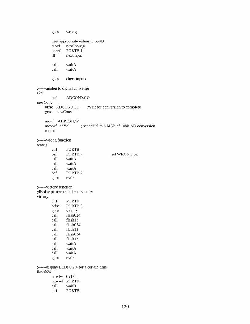
goto wrong ; set appropriate values to portB movf nextInput,0 iorwf PORTB,1 rlf nextInput call waitA call waitA goto checkInputs ;------analog to digital converter a2d bsf ADCON0,GO newConv btfsc ADCON0,GO ;Wait for conversion to complete goto newConv movf ADRESH,W movwf adVal ; set adVal to 8 MSB of 10bit AD conversion return ;------wrong function wrong clrf PORTB bsf PORTB,7 ;set WRONG bit call waitA call waitA call waitA bcf PORTB,7 goto main ;------victory function ;display pattern to indicate victory victory clrf PORTB btfsc PORTB,6 goto victory call flash024 call flash13 call flash024 call flash13 call flash024 call flash13 call waitA call waitA call waitA goto main ;------display LEDs 0,2,4 for a certain time flash024 movlw 0x15 movwf PORTB call waitB clrf PORTB
120
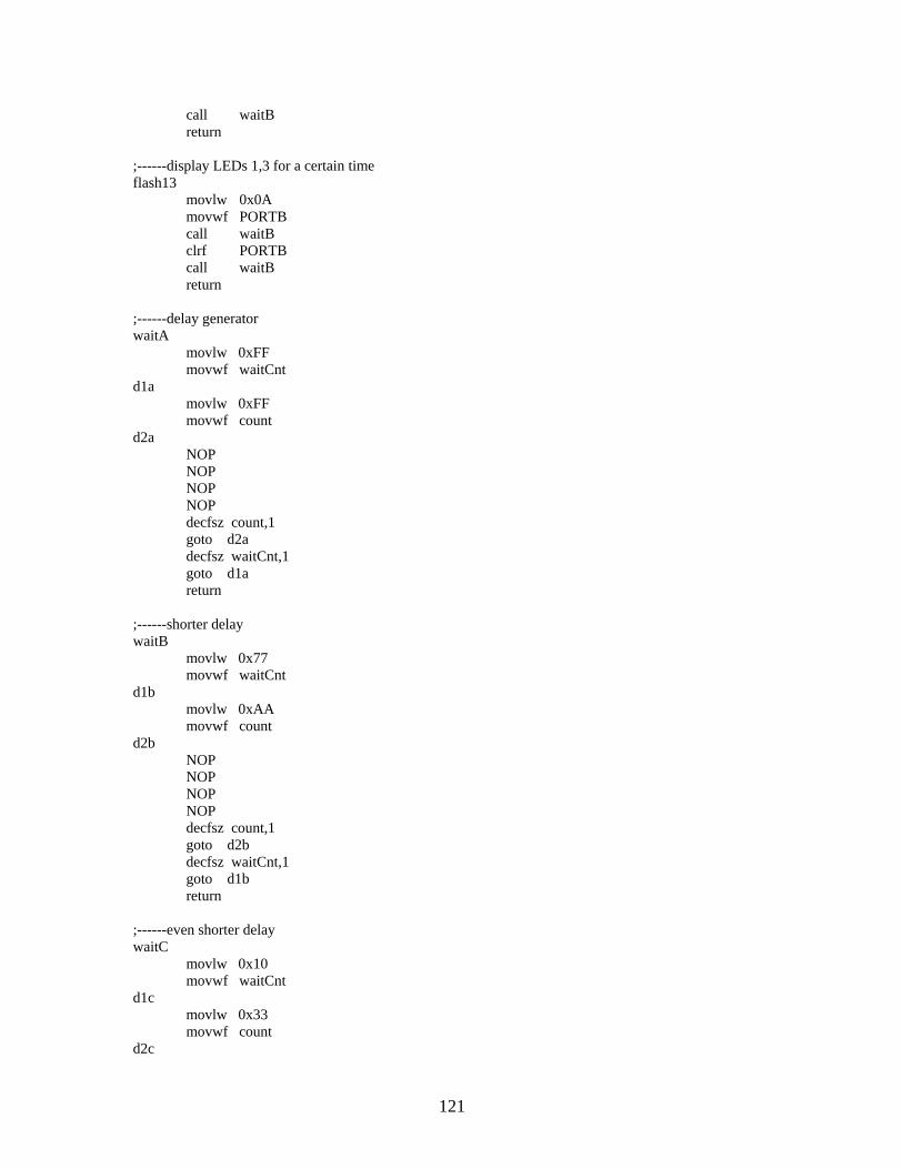
call waitB return ;------display LEDs 1,3 for a certain time flash13 movlw 0x0A movwf PORTB call waitB clrf PORTB call waitB return ;------delay generator waitA movlw 0xFF movwf waitCnt d1a movlw 0xFF movwf count d2a NOP NOP NOP NOP decfsz count,1 goto d2a decfsz waitCnt,1 goto d1a return ;------shorter delay waitB movlw 0x77 movwf waitCnt d1b movlw 0xAA movwf count d2b NOP NOP NOP NOP decfsz count,1 goto d2b decfsz waitCnt,1 goto d1b return ;------even shorter delay waitC movlw 0x10 movwf waitCnt d1c movlw 0x33 movwf count d2c
121

decfsz count,1 goto d2c decfsz waitCnt,1 goto d1c return end
122

Laser Maze Flow Diagram – PIC B
123

Laser Maze Code – PIC B
;################################################# ; Robotics Academy - Kinetic Sculpture (2003-2004) ; Jason Adrian & Marc Weintraub ; Date Finalized: 4/10/04 ; ; Target PIC: 16F88 ; Program Name: LaserMazeB ; Purpose: Input device ; Description: A game where the player must flash ; a laser over a sequence of sensors in a certain ; order to win. One of two PICs ; ;################################################# LIST p=16F88 include "P16F88.inc" ;Setting ports count EQU 0x40 nextInput EQU 0x41 adVal EQU 0x42 thisInput EQU 0x43 waitCnt EQU 0x44 org 0x000 bsf STATUS,RP0 ;bank 1 bcf STATUS,RP1 movlw 0x1F movwf TRISB movlw 0x60 movwf TRISB ;portb outputs movwf OSCCON movlw 0x40 movwf ADCON1 movlw 0x1F movwf ANSEL ;activate all AD channels bcf STATUS,RP0 ;bank 0 ;------main function ;set initial values main movlw 0x01 movwf nextInput clrf thisInput clrf adVal clrf PORTB ;------check values ;convert the value on half of the sensors from analog to digital ;also check status of PICB. If PICB returns a signal that a wrong input has ;been received then the function wrong will be called. If PICB returns ;a signal indicating that the game has been completed, the victory function
124

;is called checkInputs clrf thisInput; ; check status of PICB btfsc PORTB,5 goto wrong ; check status of PICB btfsc PORTB,6 goto victory ;check value on sensor5 movlw 0xC1 movwf ADCON0 call a2d btfsc adVal,7 bsf thisInput,0 ;check value on sensor6 movlw 0xC9 movwf ADCON0 call a2d btfsc adVal,7 bsf thisInput,1 ;check value on sensor7 movlw 0xD1 movwf ADCON0 call a2d btfsc adVal,7 bsf thisInput,2 ;check value on sensor8 movlw 0xD9 movwf ADCON0 call a2d btfsc adVal,7 bsf thisInput,3 ;check value on sensor9 movlw 0xE1 movwf ADCON0 call a2d btfsc adVal,7 bsf thisInput,4 ; check to see if an input was acquired. return to checkInputs if not movf thisInput,1 btfsc STATUS,Z goto checkInputs ; check status of PICA. If PICA is not complete, any input is an error. btfss PORTB,6 goto wrong
125
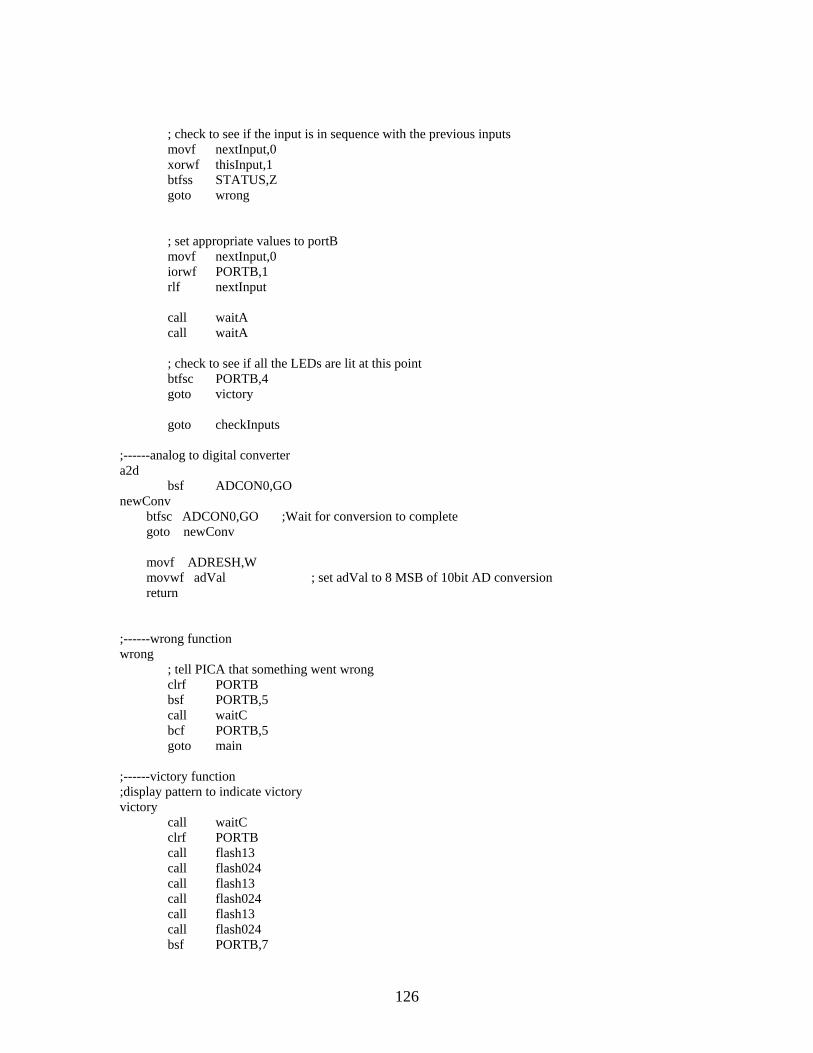
; check to see if the input is in sequence with the previous inputs movf nextInput,0 xorwf thisInput,1 btfss STATUS,Z goto wrong ; set appropriate values to portB movf nextInput,0 iorwf PORTB,1 rlf nextInput call waitA call waitA ; check to see if all the LEDs are lit at this point btfsc PORTB,4 goto victory goto checkInputs ;------analog to digital converter a2d bsf ADCON0,GO newConv btfsc ADCON0,GO ;Wait for conversion to complete goto newConv movf ADRESH,W movwf adVal ; set adVal to 8 MSB of 10bit AD conversion return ;------wrong function wrong ; tell PICA that something went wrong clrf PORTB bsf PORTB,5 call waitC bcf PORTB,5 goto main ;------victory function ;display pattern to indicate victory victory call waitC clrf PORTB call flash13 call flash024 call flash13 call flash024 call flash13 call flash024 bsf PORTB,7
126
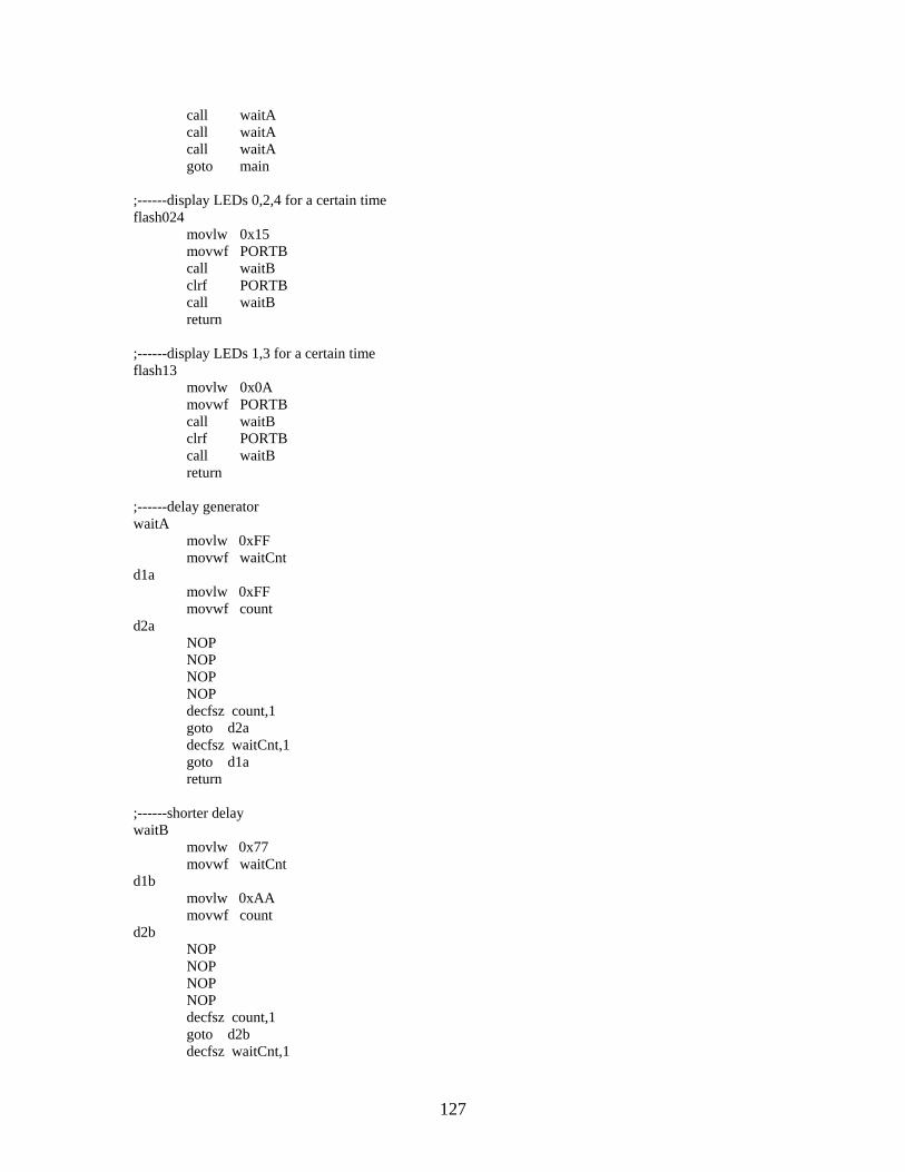
call waitA call waitA call waitA goto main ;------display LEDs 0,2,4 for a certain time flash024 movlw 0x15 movwf PORTB call waitB clrf PORTB call waitB return ;------display LEDs 1,3 for a certain time flash13 movlw 0x0A movwf PORTB call waitB clrf PORTB call waitB return ;------delay generator waitA movlw 0xFF movwf waitCnt d1a movlw 0xFF movwf count d2a NOP NOP NOP NOP decfsz count,1 goto d2a decfsz waitCnt,1 goto d1a return ;------shorter delay waitB movlw 0x77 movwf waitCnt d1b movlw 0xAA movwf count d2b NOP NOP NOP NOP decfsz count,1 goto d2b decfsz waitCnt,1
127
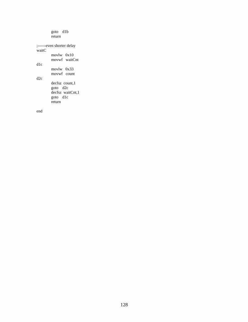
goto d1b return ;------even shorter delay waitC movlw 0x10 movwf waitCnt d1c movlw 0x33 movwf count d2c decfsz count,1 goto d2c decfsz waitCnt,1 goto d1c return end
128
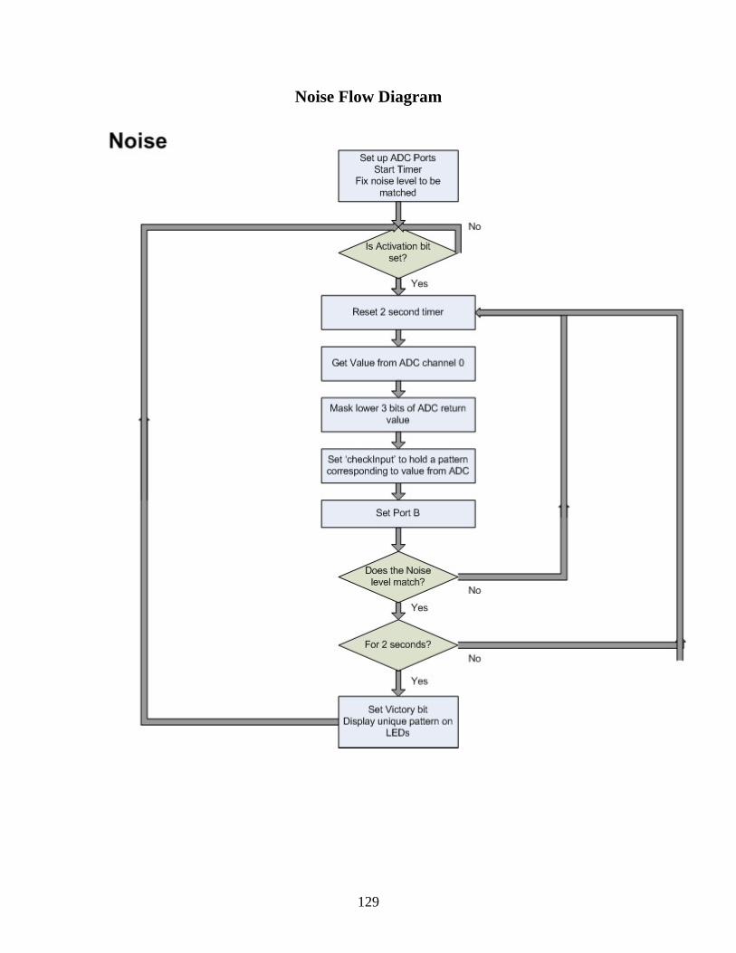
Noise Flow Diagram
129

Noise Code
;################################################# ; Robotics Academy - Kinetic Sculpture (2003-2004) ; Jason Adrian & Marc Weintraub ; Date: 4/10/04 ; ; Target PIC: 16F88 ; Program Name: Noise ; Purpose: Input device ; Description: The player is to produce noise of a ; certain loudness for a certain amount of time ; ;################################################# LIST p=16F88 include "P16F88.inc" ;Setting ports duration EQU 0x40 rightInput EQU 0x41 adVal EQU 0x42 thisInput EQU 0x43 check EQU 0x44 toggle EQU 0x45 count EQU 0x46 rightVal EQU 0x47 checkInput EQU 0x48 compareInput EQU 0x49 org 0x000 bsf STATUS,RP0 ;bank 1 bcf STATUS,RP1 movlw 0x07 movwf TRISA clrf TRISB ;portb output movlw 0x60 movwf OSCCON clrf ADCON1 movlw 0x01 movwf ANSEL ;activate all AD channels ; set timer0 movlw 0x84 movwf OPTION_REG bcf STATUS,RP0 ;bank 0 ;initialize variables initialize clrf TMR0 clrf PORTA movlw 0x01 clrf adVal clrf PORTB
130

movlw 0x41 movwf ADCON0 clrf toggle clrf rightVal clrf rightInput ;wait until activation bit is set passive btfss PORTA,2 ;check for activation bit goto passive clrf rightInput bsf rightInput,3 setVal ; simply resets count movlw d'255' movwf duration ;------get the input ;get input and display led that corresponds getInput bcf PORTA,3 ; turn off 'check input button light ; set all bits up to bit X if AD gives a certain value clrf thisInput call a2d movlw 0xE0 andwf adVal,1 clrf checkInput movf adVal,1 btfsc STATUS, Z goto setPort clrf checkInput bsf checkInput,0 bsf thisInput,0 movlw 0x20 xorwf adVal,0 movwf check btfsc STATUS, Z goto setPort clrf checkInput bsf checkInput,1 bsf thisInput,1 movlw 0x40 xorwf adVal,0 movwf check btfsc STATUS, Z goto setPort clrf checkInput bsf checkInput,2 bsf thisInput,2 movlw 0x60
131

xorwf adVal,0 movwf check btfsc STATUS, Z goto setPort clrf checkInput bsf checkInput,3 bsf thisInput,3 movlw 0x80 xorwf adVal,0 movwf check btfsc STATUS, Z goto setPort clrf checkInput bsf checkInput,4 bsf thisInput,4 movlw 0xA0 xorwf adVal,0 movwf check btfsc STATUS, Z goto setPort clrf checkInput bsf checkInput,5 bsf thisInput,5 movlw 0xC0 xorwf adVal,0 movwf check btfsc STATUS, Z goto setPort clrf checkInput bsf checkInput,6 bsf thisInput,6 movlw 0xE0 xorwf adVal,0 movwf check btfsc STATUS, Z goto setPort ;-------victory function ;display a pattern that indicate victory victory clrf PORTB call wait0 call wait0 call wait0 bcf PORTA,3 movlw 0x10 movwf count loop1 movlw 0x81
132

movwf PORTB call wait0 movlw 0x42 movwf PORTB call wait0 movlw 0x24 movwf PORTB call wait0 movlw 0x18 movwf PORTB call wait0 movlw 0x24 movwf PORTB call wait0 movlw 0x42 movwf PORTB call wait0 decfsz count goto loop1 return ;------set the LEDs connected to port ;set values to PORTB ;wait until noise is activated for certain amount of time setPort movf checkInput,0 movwf compareInput movf thisInput,0 movwf PORTB movf rightInput,0 xorwf checkInput,0 movwf check btfss STATUS, Z goto reset here btfss INTCON,TMR0IF ; skip if interrupt is not enabled goto here bcf INTCON,TMR0IF ; clear interrupt bit decfsz duration goto getInput goto victory ;------analog to digital converter a2d bsf ADCON0,GO newConv btfsc ADCON0,GO ;Wait for conversion to complete goto newConv
133

movf ADRESH,W movwf adVal ; set adVal to 8 MSB of 10bit AD conversion return ;------wait function ;wait for a fixed duration of time wait movlw d'121' movwf duration bcf INTCON,TMR0IF ; clear interrupt bit wait4int btfss INTCON,TMR0IF ; skip if interrupt is not enabled goto wait4int bcf INTCON,TMR0IF ; clear interrupt bit decfsz duration goto wait4int return ;------shorter wait ;wait for a shorter duration of time wait0 movlw d'07' movwf duration bcf INTCON,TMR0IF ; clear interrupt bit wait4int0 btfss INTCON,TMR0IF ; skip if interrupt is not enabled goto wait4int bcf INTCON,TMR0IF ; clear interrupt bit decfsz duration goto wait4int0 return end
134

Turnstile Code ;################################################# ; Robotics Academy - Kinetic Sculpture (2003-2004) ; Jason Adrian & Marc Weintraub ; Date Finalized: 4/10/04 ; ; Target PIC: 16F84A ; Program Name: Stepper Motor ; Purpose: Control the stepper motor used for the ; turnstile. ; Description: This program sequences the four ; coils in the stepper to rotate 120 ; degrees one direction, pause, then reverse ; direction and return to the starting point ; ;################################################# LIST p=16F84A include "P16F84a.inc" _CONFIG_0x3d18 ;Setting ports count1 EQU 0x40 count2 EQU 0x42 input EQU 0x48 looper EQU 0x46 org 0x00 bsf STATUS, RP0 movlw 0x0f ;A is input movwf TRISA clrf TRISB ;B is output bcf STATUS, RP0 main movf PORTA,0 movwf input btfss input,0 goto main movlw 0x13 movwf looper forward movlw 0x03 ;step sequence movwf PORTB ;to motor driver circuitry call wait movlw 0x06 movwf PORTB call wait
135
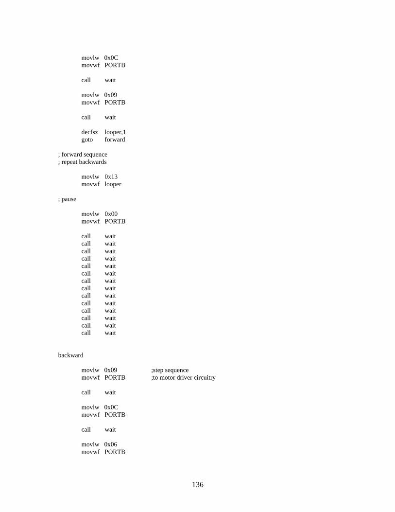
movlw 0x0C movwf PORTB call wait movlw 0x09 movwf PORTB call wait decfsz looper,1 goto forward ; forward sequence ; repeat backwards movlw 0x13 movwf looper ; pause movlw 0x00 movwf PORTB call wait call wait call wait call wait call wait call wait call wait call wait call wait call wait call wait call wait call wait call wait backward movlw 0x09 ;step sequence movwf PORTB ;to motor driver circuitry call wait movlw 0x0C movwf PORTB call wait movlw 0x06 movwf PORTB
136

call wait movlw 0x03 movwf PORTB call wait decfsz looper,1 goto backward goto main ;delay loop wait movlw 0x66 ; else load count1 with movwf count1 d1a movlw 0x66 ; else load count2 with movwf count2 d2a decfsz count2,1 goto d2a decfsz count1,1 goto d1a return end
137

Circuit Photos
Simon Circuit
Distance Piano Circuit
138

Grip Circuit
Laser Maze Circuit
139
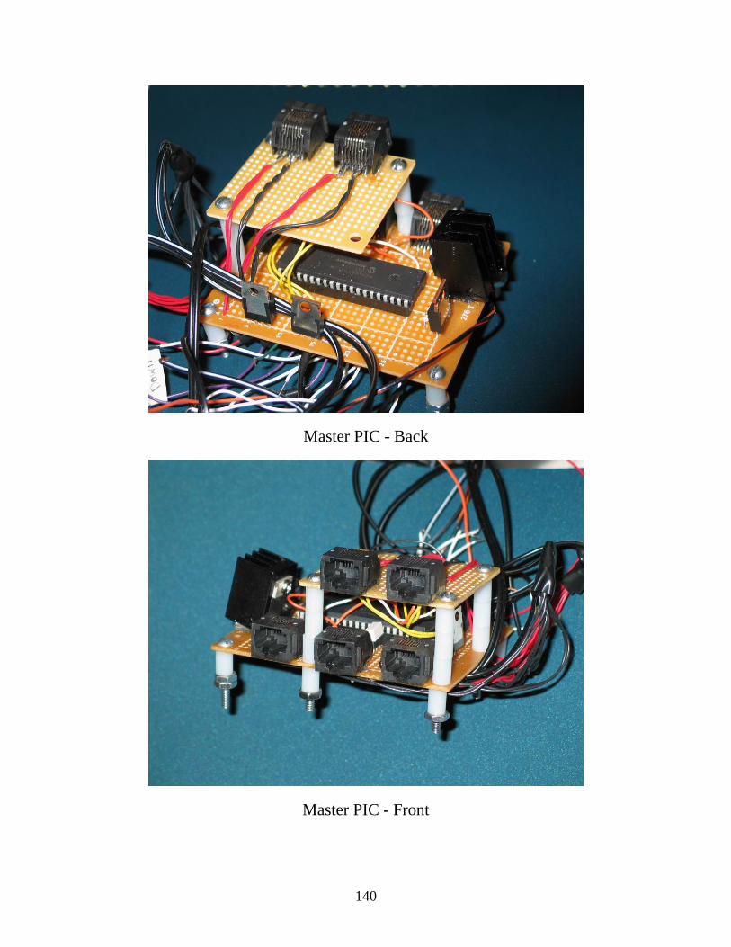
Master PIC - Back
Master PIC - Front
140