logic express 7.1 dedicated control surface support (manual)
TRANSCRIPT

Logic Express 7.1Dedicated Control Surface Support

Apple Computer, Inc.© 2004–2005 Apple Computer, Inc. All rights reserved.
Under the copyright laws, this manual may not be copied, in whole or in part, without the written consent of Apple. Your rights to the software are governed by the accompanying software licence agreement.
The Apple logo is a trademark of Apple Computer, Inc., registered in the U.S. and other countries. Use of the “keyboard” Apple logo (Option-Shift-K) for commercial purposes without the prior written consent of Apple may constitute trademark infringement and unfair competition in violation of federal and state laws.
Every effort has been made to ensure that the information in this manual is accurate. Apple Computer, Inc. is not responsible for printing or clerical errors.
Apple Computer, Inc.1 Infinite LoopCupertino, CA 95014-2084408-996-1010www.apple.com
Apple, the Apple logo, Aqua, Final Cut, Final Cut Pro, FireWire, iBook, iMac, iPod, iTunes, Logic, Mac, Macintosh, Mac OS, PowerBook, Power Mac, Power Macintosh, and QuickTime are trademarks of Apple Computer, Inc., registered in the U.S. and other countries.
Finder and GarageBand are trademarks of Apple Computer, Inc.
AppleCare is a service mark of Apple Computer, Inc.
Helvetica is a registered trademark of Heidelberger Druckmaschinen AG, available from Linotype Library GmbH.
Other company and product names mentioned herein are trademarks of their respective companies. Mention of third-party products is for informational purposes only and constitutes neither an endorsement nor a recommendation. Apple assumes no responsibility with regard to the performance or use of these products.
1 Contents
Preface 7 Introduction7 What Are Control Surfaces?8 How Control Surface Integration Works
Chapter 1 11 Control Surface Setup11 Control Surface Plug-ins12 About Software and Firmware12 Getting Started14 Installing and Setting Up Control Surfaces15 Control Surface Group16 Setup Window Parameters21 Control Surface Preferences24 Customizing Control Surfaces26 The Controller Assignments Editor28 Tips
Chapter 2 29 Logic Control29 Set Up30 The Displays32 The Channel Strip(s)36 The Assignment Zone48 Fader Bank Zone50 Master Fader50 Display Zone52 The Function Key Zone53 The Global View Zone54 Function Button Zone57 The Transport Zone63 The Cursor/Zoom Key Zone64 The Jog/Scrub Wheel Zone64 Assignment Overview
Chapter 3 75 Frontier Design TranzPort75 Set Up
3
4
75 LCD75 Assignment Overview
Chapter 4 79 J.L.Cooper CS-32 MiniDesk79 Set Up79 Assignment Overview
Chapter 5 85 J.L.Cooper FaderMaster 4/10085 Requirements85 Set Up86 Assignment Overview
Chapter 6 87 Korg microKONTROL and KONTROL4987 Set Up87 Assignment Overview
Chapter 7 93 Mackie C493 Set Up93 V-POTs, V-SELECTs96 Buttons at Bottom98 Marker Overlay98 Track Overlay98 Channel Strip Overlay99 Function Overlay
Chapter 8 101 Roland SI-24101 Set Up101 Assignment Overview
Chapter 9 107 Tascam FW-1884107 Introduction107 Set Up107 Assignment Overview
Chapter 10 115 Tascam US-2400115 Set Up115 Assignment Overview
Chapter 11 121 Tascam US-428 and US-224121 Set Up121 Assignment Overview
Appendix A 125 Logic Control—Specifications125 Logic Control (Base Unit)127 Logic Control XT (Extension Unit)
Contents
Appendix B 129 Logic Control—MIDI Implementation129 SysEx Message Header130 Global Control Messages132 Common Control Messages
Appendix C 141 Logic Control—Control Surface Layout and IDs
Appendix D 145 Logic Control—MIDI Implementation Chart
Index 147
Contents 5


Pref
ace
Introduction
This manual covers the control surface support of Logic Express 7. Please read it thoroughly to make the most of your new controller(s).
Using a mouse and computer keyboard to do things normally done on an analog mixer can be disconcerting. Clicking an onscreen fader or knob, and dragging the mouse to achieve a silky smooth fade or pan move is difficult, if not impossible, for many users.
Use of a control surface, such as the Logic/Mackie Control, provides you with hands-on control of most of Logic Express 7’s real time parameters. Move a fader and Logic’s on-screen fader will move with it. Similarly, when you make a fader move on-screen, the control surface fader moves (this only applies to control surfaces equipped with motorized faders). Adjust EQ parameters by turning one of your control surface’s knobs and Logic will update instantly.
What Are Control Surfaces?Control surfaces are hardware units that enable the operation of Logic Express using faders, rotary knobs, switches and displays.
There are a number of simple control surfaces that feature conventional faders and no displays. More progressive units are equipped with motorized faders, rotary encoders, LED rings and programmable displays. The more feedback a control surface provides, the easier it is to use, as you don’t need to watch the computer screen in order to determine what mode the unit is currently in.
Control surfaces—dependent on the options (buttons, knobs, switches, displays and so on) available—have the potential to:• control all Logic transport functions• adjust instrument, input,bus, aux, and audio channel volume and pan levels• control Channel EQ and parameters• select and control all effect and Instrument parameters• select, solo, mute and arm tracks
7
8
• set and adjust send parameters• remotely switch between Screensets• scrub MIDI and audio• zoom in on individual tracks• create, delete and move between markers, and much more
For live use, control surfaces are ideal. The performing musician only needs to take a laptop, equipped with suitable audio and/or MIDI interfaces, a keyboard, and a control surface to a live event. Some units available nowadays incorporate a keyboard, audio interface, control surface and MIDI interface into a single package.
Given that Logic Express 7’s track automation facilities can be active, even when not in record mode, you can capture your “live” real time changes for later recall. This ensures that you’ll never again lose that “once-in-a-lifetime” performance—on stage or in the studio.
How Control Surface Integration WorksLogic Express 7 features dedicated support for a number of control surface models. This is achieved through several plug-ins that are directly integrated into Logic. Some plug-ins support multiple, similarly-featured control surface models.
Note: Although many other control surfaces are supported, the Logic/Mackie Control, C4, and XT control surface units are recommended for use with Logic.
Logic also allows you to program new assignments for unsupported control surfaces. This facility allows you to extend the use of faders, knobs and switches, either directly or through the use of modifier commands.
You can use any combination of control surfaces with Logic Express 7.
Universal information, that applies to all control surfaces, is covered in the following chapter. Please read this before taking a look at the dedicated section on your control surface(s).
A detailed overview of installation and other control surface setup parameters is found in Chapter 1, “Control Surface Setup,” on page 11. Please read this, as it contains a lot of useful information that will help you to customize and/or make the most of your control surface(s).
Important: Specific information on device setup is found at the beginning of the relevant chapter for your control surface (see the table below).
Preface Introduction
It is assumed that you are familiar with the basic use and terminology of Logic Express 7. As such, the functionality and uses of individual Logic parameters are not covered in this documentation. Please consult your Logic Reference manual or the Online Help, if you require further information.
You are strongly encouraged to press buttons, move sliders and turn the knobs of your control surface while reading through the following chapters. This will help you to get a “feel” for how your control surface works, and how the various parts of the control surface interact with one another, and Logic.
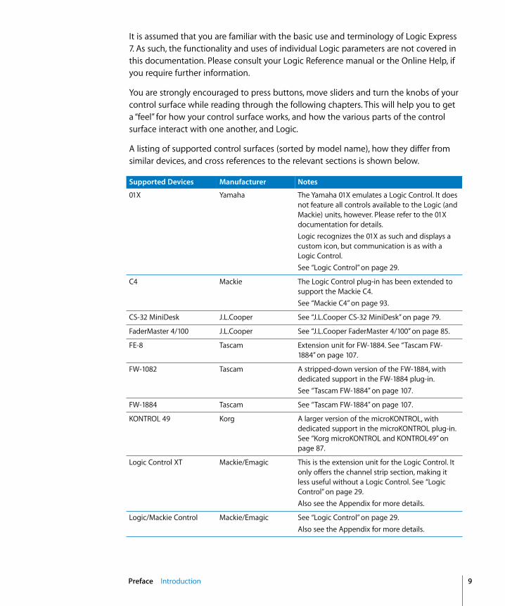
A listing of supported control surfaces (sorted by model name), how they differ from similar devices, and cross references to the relevant sections is shown below.
Supported Devices Manufacturer Notes
01X Yamaha The Yamaha 01X emulates a Logic Control. It does not feature all controls available to the Logic (and Mackie) units, however. Please refer to the 01X documentation for details.Logic recognizes the 01X as such and displays a custom icon, but communication is as with a Logic Control.See “Logic Control” on page 29.
C4 Mackie The Logic Control plug-in has been extended to support the Mackie C4. See “Mackie C4” on page 93.
CS-32 MiniDesk J.L.Cooper See “J.L.Cooper CS-32 MiniDesk” on page 79.
FaderMaster 4/100 J.L.Cooper See “J.L.Cooper FaderMaster 4/100” on page 85.
FE-8 Tascam Extension unit for FW-1884. See “Tascam FW-1884” on page 107.
FW-1082 Tascam A stripped-down version of the FW-1884, with dedicated support in the FW-1884 plug-in.See “Tascam FW-1884” on page 107.
FW-1884 Tascam See “Tascam FW-1884” on page 107.
KONTROL 49 Korg A larger version of the microKONTROL, with dedicated support in the microKONTROL plug-in. See “Korg microKONTROL and KONTROL49” on page 87.
Logic Control XT Mackie/Emagic This is the extension unit for the Logic Control. It only offers the channel strip section, making it less useful without a Logic Control. See “Logic Control” on page 29.Also see the Appendix for more details.
Logic/Mackie Control Mackie/Emagic See “Logic Control” on page 29.Also see the Appendix for more details.
Preface Introduction 9

10
Mackie Control Mackie The original Mackie Control hardware is similar to the Logic Control. The front panel legend is different, however. You should request a Logic Control Lexan Overlay from Mackie. As Logic also recognizes the Mackie Control protocol, you may use any firmware version. If you have firmware version 1.02 or higher, you can freely use either the Logic Control or Mackie Control mode. See “Logic Control” on page 29.
Mackie Control Extender Mackie Mackie Control version of the Logic Control XT. As Logic also recognizes the Mackie Control protocol, you may use any firmware version. If you have firmware version 1.02 or higher, you can freely use either the Logic Control or Mackie Control mode.See “Logic Control” on page 29.
Mackie Control Universal Mackie A Mackie Control with Logic Control silk screening (legend) and firmware version 2.0 or higher (including HUI emulation). As Logic also recognizes the Mackie Control protocol, you may use any firmware version. If you have firmware version 1.02 or higher, you can freely use either the Logic Control or Mackie Control mode.See “Logic Control” on page 29.
microKONTROL Korg See “Korg microKONTROL and KONTROL49” on page 87.
SI-24 Roland See “Roland SI-24” on page 101.
Smart Console SmartAV SmartAV offers a Logic plug-in for the Smart Console. This plug-in is not included in the Logic package.
TranzPort Frontier Design Group See “Frontier Design TranzPort” on page 75.
US-224 Tascam A stripped-down version of the US-428, with dedicated support in the US-428 plug-in.See “Tascam US-428 and US-224” on page 121.
US-2400 Tascam Logic has support for the US-2400’s native mode. In contrast to its Logic Control mode, all controls, including the joystick, are supported.See section “Tascam US-2400” on page 115.
US-428 Tascam See “Tascam US-428 and US-224” on page 121.
Supported Devices Manufacturer Notes
Preface Introduction
1
1 Control Surface Setup
Logic offers dedicated support for a number of control surfaces, plus the option to program unsupported devices.
The following chapter describes functions applicable to all control surface models. Specific documentation for various models is available in the following chapters.
Control Surface Plug-insDedicated control surface support is achieved through the use of special plug-in files. These files are automatically added when Logic is installed.
They are located in the Contents > MIDI Device Plug-ins sub-folder of the Logic application bundle (to view the bundle contents, Control or right-click on the Logic application icon, and choose Show Package Contents from the menu). Logic also checks for control surface plug-ins in the (optional) “/Library/Application Support/Logic/MIDI Device Plug-ins” and “~/Library/Application Support/Logic/MIDI Device Plug-ins” (the “~” denotes your user home directory) folders.
When new control surface plug-ins are released independently from a Logic update, please place them in the folders described above (or as advised in the documentation supplied with the plug-in).
11

12
About Software and FirmwareMost control surfaces have no “intelligence” of their own. Their functionality is host software-based, making them reliant on Logic to tell them what to do/how to behave. What this means is that control surfaces cannot perform any function that Logic itself isn’t capable of. It also means that if Logic is not booted, most control surface units will do nothing at all.
This reliance on the host application makes your control surface the ultimate upgradable hardware. As new functions are added to Logic, or you create new assignments (see Chapter 1), your control surface will be able to access and control them.
Most control surface units do, however, have a form of software called “firmware.” This firmware is much like the BIOS found in your computer. New behaviors—at a hardware level—such as improved control of fader servo motors and changes to the display can be made via firmware updates.
The firmware is usually stored on an EEPROM (Electronically Erasable Programmable Read Only Memory) chip. It can often be updated via a simple MIDI dump procedure, in the form of a MIDI file.
Should new firmware become available, you can simply download the appropriate MIDI file and play it to your control surface(s), which will be updated accordingly. The steps required to perform a firmware update will be outlined in the documentation that accompanies the MIDI file. Please read this before attempting any update.
Note: Some control surfaces may require a physical chip replacement for firmware updates. Please contact the manufacturer of your device for details.
Getting StartedTo make use of your control surface, you will require:• An installed, authorized copy of Express 7• If a USB or FireWire equipped device (such as a Yamaha 01X)—a free USB or FireWire
port. This should preferably be a direct USB/FireWire connection with the computer, rather than via a USB/FireWire hub. Please refer to the documentation provided by the manufacturer of your control surface.
• If a MIDI-only device (such as a Logic Control)—a free MIDI in and out port for each unit, on any suitable MIDI interface. As an example; if using a Unitor 8 or AMT 8, which feature 8 MIDI in and 8 MIDI out ports, with one Logic Control and one Logic Control XT, you will need to use two of the Unitor8/AMT8’s MIDI ins and two of its MIDI outs.
• An installed driver (if required by your control surface) that is supported by the operating system version being used.
Chapter 1 Control Surface Setup

Important: Your MIDI interface must feature driver software that supports SysEx communication. Please consult the documentation that shipped with your MIDI interface.
The number of units that can be run simultaneously is dependent on the availability of free MIDI in and out, FireWire or USB ports on your system. In a standard setup, a single control surface will be used alone, or accompanied by one or more units. It is also possible to make use of several units to create a Control Surface Group, as discussed in the Control Surface Group section on page 15.
The use of multiple control surfaces expands on the number of tracks, parameters and so on that can be controlled with individual faders, knobs and switches. As an example, the Logic/Mackie Control XT units are basically identical to the channel strip section (fader, V-POT, and LCD) of the main Logic/Mackie Control unit. The Mackie C4 features a number of V-POTs, but no faders. You may add as many XT, C4 or other control surface units as you wish to your Logic system, provided enough MIDI in and out ports are available.
Connecting the Unit(s)Connect your (MIDI) control surfaces as shown in the diagram below.
As mentioned earlier, each MIDI control surface must have a discrete MIDI in and MIDI out connection. Do not “daisy-chain” other MIDI devices via MIDI thru to the MIDI in or out ports used by control surfaces, as this may result in data errors.
FireWire and USB units are connected via a single cable to the computer. It is generally recommended that this is a direct connection with the Macintosh, rather than via a FireWire/USB hub. Daisy-chaining or the use of hubs can result in data errors.
Computer MIDI Interface
Optional Footswitches
Chapter 1 Control Surface Setup 13

14
Optional Footswitches and PedalsIf your control surface features suitable connectors, you may use optional foot switches to remotely control start/stop and other functions. This may be useful when using guitars or other instruments that require two-handed playing.
Power UpOnce everything is connected, press the power switch on your control surface. Once powered, the displays and/or LEDs will illuminate and the LCD (if applicable) will generally display a welcome message (often including the firmware version number). Each fader will slide to the top, and back to the bottom of its travel on most motorized control surfaces. This self-diagnostic power-on procedure indicates that your units are functioning correctly.
Your computer and MIDI interface can be powered up before or after initialization of your control surface units. Logic can be started either before or after the units have completed initialization.
Installing and Setting Up Control SurfacesSome control surface units (Logic/Mackie Control, for example) will automatically be detected when Logic is launched. Units which are not detected automatically can be added via the Setup window. This is accessed via the Setup option in the Preferences > Control Surfaces menu.
Installation is very easy (and is covered in the Set Up section of the chapter on your specific device). Some devices may require different or additional steps, but generally, all you need to do is select the device(s) that you wish to use in Logic, as follows:
To install control surfaces using Logic’s Scan function:1 Choose New > Install, and in the ensuing Install window, select the desired device from
the list.
Note: You may select one or more models. To select more than one model, select them with Command held down. If you select more than one model, Logic performs the desired operation for each model in turn.
2 Press the Scan button. You can also press Enter or double-click the device name.
Logic will then analyze your MIDI system, and will automatically install the devices it finds, including the correct connection settings.
Note: The Scan function is preferable to manual installation, as ProductName is able to gather the maximum amount of information about the devices.
If you don’t want to select the models to be scanned manually, you can also click Scan all. This will search for all supported control surface units on all MIDI ports. Please be aware that this may take a while.
Chapter 1 Control Surface Setup

Some control surfaces don’t support automatic scanning. Such devices must be added manually to your setup. In this scenario, you will need to manually set the MIDI In and Out port parameters.
To manually add the selected devices to your system:1 Select the desired devices from the list in the Install window.
2 Click the Add button.
Note: Alternatively you can Option-double-click the desired device.
If a control surface of the selected type already exists in your setup, you will be asked whether or not you really want to add the new device. You will need to manually alter the MIDI In and Out port values in the device parameters to match those of the connected unit.
Once you have completed the scanning or installation of the devices, click Done. The Install window will close.
Rebuilding DefaultsThe Preferences > Control Surfaces > Rebuild Defaults option re-initializes the support of all connected control surfaces.
Control Surface GroupIf you have multiple control surface units, you can define how they relate to each other, and build a Control Surface Group. A Control Surface Group consists of a number of control surface units (using the same plug-in) which are combined to create a single, unified (and larger) control surface.
When multiple control surface units are combined, you can independently determine the default behavior for each physical device. This is discussed in the Device Parameters (p. 16) section.
To build a Control Surface Group out of several units:m Simply arrange their icons (in the Setup window) in a single horizontal row—by
dragging each icon to the desired onscreen location.
The order of the icons from left to right also defines how the tracks and parameters are arranged on the units.
Note: The placement of your control surface units in relation to each other should be the same onscreen as in the real-world. Simply drag ’n drop the desired icon horizontally in your Control Surface Group to do so.
Chapter 1 Control Surface Setup 15

16
Setup Window ParametersThe three Parameter boxes along the left edge of the Setup window allow you to configure your control surface setup to meet your needs.
Device ParametersEach control surface unit must be connected to an independent MIDI in and out port (or corresponding USB/FireWire port, designated as a MIDI port by the device driver). The automatic setup or Scan procedure should have found, and set, the correct MIDI in/out port settings for each unit.
In the event that the MIDI in or out port identification is incorrect, you can manually select the appropriate one for the unit. To do so, click-hold on the MIDI Input and Output pull-down menus, and select the appropriate port(s) of your MIDI interface/device.
Some devices allow you to define a device ID (or global/basic channel). This can be set in this area. Module name, model name and firmware version are also displayed in the device parameters.
Special ParametersSome control surfaces may allow the definition of “special” parameters. An example of this is fader touch sensitivity. Such parameters can be found in the Special Parameters area. A detailed description can be found in the documentation of the particular control surface plug-in.
Control Surface Group ParametersThe following parameters are shown in the Setup window. They apply to the Control Surface Group associated with the selected device.
Many (if not all) Control Surface Group parameters can also be changed directly from the control surface. The parameter display in the Setup window is for information purposes only.
Any changes to settings (made here, or on the control surface) are saved in a preferences file, which is independent of the Logic program preferences: it’s named “com.apple.logic.Express.cs”, and is located in ~/Library/Preferences/Logic.
Display ParametersFlip ModeMany control surfaces offer both a fader and a rotary encoder for each channel strip. Flip Mode allows you to swap the encoder assignment with that of the fader for each channel. Alternately, you can assign both controls to the same parameter.
There are four “flip” or “swap” modes.• Off—disables Flip Mode, making the fader act as a volume control.
Chapter 1 Control Surface Setup
• Duplicate—makes both the fader and encoder active for the currently selected encoder parameter.
• Swap—swaps the fader and encoder, making the fader a pan control and the encoder a channel volume control, for example.
• Mute—disables the faders. This is useful for situations where recording is taking place in the same room as the control surface, and you wish to avoid the mechanical noise of the faders. Any existing automation data will still function as per normal.
Display ModeIf there is insufficient space available for the display of both the parameter name and value (on the control surface LCD), you can specify what is displayed here:
• Value—displays the parameter value.• Name—displays the parameter name.
Clock DisplayIf your control surface features a song position dipslay, the Clock Display parameter allows you to set the display mode:• Beats—the song position display shows Bars/Beats/(optional) Sub Division/Ticks.• SMPTE—as above, but in Hours/Minutes/Seconds/Frames.
Track View ModeThis parameter determines which tracks or channels are displayed:• Mixer—displays channels in their order of appearance in the Track Mixer window
(while Global mode is disabled). Channel Strip 1 in the Track Mixer is equivalent to channel 1 on the control surface, Channel Strip 2 in the Track Mixer is equivalent to channel 2 and so on. Instruments/channels used by multiple tracks are merged into one channel. Mixer View is the default mode of most devices, including the Logic/Mackie Control.
• Global—displays all Objects of certain type(s)—MIDI or Bus channels, for example—independently of their usage by tracks. They merely need to be defined as an Environment Object. The Object types to be displayed are defined by another parameter which is not shown in the parameter list. If a control surface supports switching to Global View, it also allows you to define which Objects to display. The Track Mixer window’s contents automatically follows the state of the GLOBAL VIEW buttons. It also sets Object filters in accordance with the Object classes activated in Global View.
• Arrange— Arrange View is similar to Mixer View, with one exception: Namely, if multiple tracks play back via the same Environment Object, all of them will be displayed on separate channel strips. The Hide button status is taken into account, with tracks hidden in the Arrange window also being hidden on the control surface.
These modes are mutually exclusive, so if you’re in one View mode, you cannot be in another.
Chapter 1 Control Surface Setup 17
18
Mixer View Fader BankThis parameter affects the Track View mode by shifting channels by the defined amount. Imagine that your control surface has eight channel strips, and you were looking at audio tracks 1 to 8 in the Arrange window. These would appear as channels 1 to 8 on the control surface. Using the Mixer View Fader Bank parameter, you could offset this view by a defined number of channels, looking at audio tracks 3 to 11, for example.
Global View Fader BankThe Global View Fader Bank parameter does the same thing as the Mixer View Fader Bank, but only applies if multiple Object types are enabled. When single Object types are enabled, there are separate fader bank parameters (these aren’t displayed in the parameter list).
Track/Channel ParametersTrack ParameterDefines the current Track Assignment behavior for the encoders. Options are:• Volume—encoders adjust channel volume.• Pan—encoders adjust channel panorama.• Mode—encoders adjust/select channel mode (mono/stereo).• Input—encoders adjust/select channel input source.• Output—encoders adjust/select channel output (main outs/busses/).• Automation—encoders adjust/select channel automation mode.• Displayed parameter—encoders adjust the automation parameter displayed in the
Arrange window. This is especially useful if you set the control surface to Arrange View mode, and your Arrange window shows multiple sub-tracks with various parameters.
EQ BandThe EQ Band parameter allows you to select the current EQ band, if you are editing one Channel EQ or Linear Phase EQ parameter for all tracks in the EQ Multi Channel View.
EQ ParameterThis parameter determines which parameter of the selected EQ Band is edited by the encoders in EQ Multi Channel View:• Frequency—encoders determine the frequency of the selected band.• Gain—encoders change the gain of the selected EQ band. For the Low Cut (band 1)
and High Cut (band 8) bands of the Channel and Linear Phase EQ, this parameter controls the slope.
• Q—encoders change the Q factor of the selected band.• On/Off—encoders bypass the selected EQ band.
EQ Parameter PageThe EQ Parameter Page parameter defines the EQ parameter displayed in EQ Channel Strip View.
Chapter 1 Control Surface Setup

To explain: Logic’s Channel and Linear Phase EQ feature 4 bands per audio channel, each band has four parameters. Every one of these parameters can be accessed with your control surface.
If you use a control surface that does not display all EQ parameters, you need to step trough the parameter “pages.” As an example: Imagine you are using a single, eight channel control surface. You can directly affect parameters 1 to 8 with knobs/sliders 1 to 8—once you’ve switched to EQ Channel Strip Edit View. You then need to switch by a “page” to access parameters 9 to 16.
Send/Plug-in ParametersSend SlotThe Send Slot parameter determines the currently selected Send slot. Normally, a value of 1 would be used, as this accesses the first (top) Send on each channel. A value of 2 accesses the second Send, and so on, up to the eighth Send. The Send slots are accessed by pressing the Up/Down buttons on your control surface—if applicable.
Send ParameterDefines the Send parameter edited with the encoders when in the Send Multi Channel view:• Destination:—encoder is used to determine the bus channel number for the Send
slot.• Level—encoder is used to adjust the Send level.• Position—encoders set Pre and Post fader modes.• Mute—encoders mute/unmute the selected Send slot.
Send Parameter PageMuch like the EQ parameters, up to 32 parameters are available in Send Channel Strip View on a given channel (Eight Send slots multiplied by the four parameters listed above). Send Parameter Page determines the current page for these parameters.
Split: no. of upper parametersControl surfaces that support split mode allow the display of two separate parameter sections within one plug-in (or even different plug-ins). They are called Split Upper and Split Lower.
This parameter defines how many encoders belong to Split Upper, leaving the remaining encoders to Split Lower. A value of 0 means that Split Mode is off—all encoders then belong to the Split Upper area.
Instrument Parameter PageThe Instrument Parameter Page parameter determines the parameter (counted from 1) which is assigned to the left-most encoder when editing an Audio Instrument. The next Instrument parameter is assigned to encoder 2, and so on.
With Split Mode enabled, this applies to Split Upper.
Chapter 1 Control Surface Setup 19

20
Inst Parameter Page (Split Lower)As with Instrument Parameter Page, but for Split Lower.
Insert SlotDetermines the current Insert slot number for both selecting a plug-in (in Plug-in Channel Strip View) and editing its parameters. A value of 1 accesses the first (top) plug-in slot on each channel. A value of 2 accesses the second plug-in slot, and so on.
With Split Mode enabled, this applies to Split Upper.
Insert Slot (Split Lower)As with Insert Slot, but for Split Lower.
Plug-In Parameter PageAs with Instrument Parameter Page, but for editing plug-ins. Having these parameters separate allows you to quickly switch between editing an instrument and an effect on a track, without the need to adjust the parameter page every time.
With Split Mode enabled, this applies to Split Upper.
Plug-In Parameter Page (Split Lower)As with Plug-In Parameter Page, but for Split Lower.
TrackSpecifies the currently displayed track for Channel Strip Views. With Split Mode enabled, this applies to Split Upper.
Track (Split Lower)As with Track, but for Split Lower.
Track LockWhen this parameter is set to “on,” selecting a track in Logic does not change the Track and Track (Split Lower) parameters. In other words, the control surface group continues to display the same track, independent from the currently selected track.
When Track Lock is disabled, the control surface group automatically switches to the selected track, whenever a track is selected.
Other ParametersTrack Name FormatChanges the track name display to show the track name alone, or the track name, and its track number. As an example, a track named “Audio1” may actually be placed on track 12 in the Arrange window. When a value of #:Name is toggled, “Audio1” would be displayed as “12:Au1”.
Parameter Page Shift ModeDefines whether the parameter is shifted by an entire “page” or by one parameter.
Chapter 1 Control Surface Setup

Relative Change ModeThis determines the behavior of assignments with a relative value change mode (e.g. rotary encoders).• Coarse: the parameter can be adjusted in coarse steps.• Full: the parameter value is set to its minimum if delta < 0. If greater than 0, it is set
to the maximum. This way, you can jump to the last or first track instead of the next or previous bank.
• Fine: the value is incremented/decremented in fine steps—one tick/by one “unit.” In this mode, the adjustable resolution is ignored, and the highest possible resolution is used instead. As an example, using the Sample Delay parameter: every encoder rotation tick in/decreases the value by 1 ms, no matter what the value of the resolution.
Coarse is the mode used by default.
Control Surface PreferencesThe Control Surface preferences window is accessible via the Logic > Preferences > Control Surfaces > Preferences menu.
Note: You can also use the global Control Surfaces Preferences key command.
GeneralResolution of Relative ControlsThis defines the default resolution of controls that change values in a relative manner. The default is 128 steps.
As an example: adjusting the Sample Delay (value range 0 to 4000 ms) in/decreases the value by 40 ms with every encoder rotation “tick,” if resolution is set to 100.
Maximum MIDI Band WidthThis slider determines the maximum amount of MIDI bandwidth that can be used by your control surface. By default, this is set to 50%, which should be suitable for most situations. You can adjust the value if you find that your MIDI or automation playback is being affected.
Touching fader selects trackActivation of this parameter will automatically select the track that corresponds to the selected fader. You require a device that features touch-sensitive faders for this functionality to work.
Jog resolution depends on horizontal zoomIf your control surface features a jog/shuttle wheel (or similar), the precision of any scrubbing is affected by the horizontal zoom level of Logic. To retain a consistent resolution, regardless of Logic window zoom levels, disable this checkbox.
Chapter 1 Control Surface Setup 21

22
Pickup ModeIf your control surface does not feature motorized faders and knobs, parameter changes—caused by playing back existing automation—are not reflected on its surface.
Such control surfaces usually offer a Pickup mode. In Pickup mode the current value must be reached (“picked up”) by the control before a value change can occur. This prevents sudden “jumps” of parameter values after parameter changes caused by playing back automation. A display (usually a pair of LED’s) will indicate the direction/distance you need to move the controller to match (also known as “NULL”) the settings shown in Logic. Once you have matched the onscreen values, deactivate Pickup mode, and start automating.
When the Pickup mode option is disabled, adjusting a fader modifies the parameter immediately.
Multiple Controls per ParameterThese parameters determine whether one, or multiple, encoders are used per parameter when editing plug-ins or audio instruments.
When multiple encoders are used per parameter, the encoders are subdivided into groups (for example 1/2, 3/4, 5/6, 7/8). The first encoder of each sub-division controls the parameter shown in the display. The remaining encoder(s) are inactive.
Using more than one encoder per parameter shows fewer parameters at any given time, but you gain space on the LCD to cater for longer parameter names and values. The more control surfaces you have within a Control Surface Group, the more you benefit from this feature.
The Multiple controls per parameter pull-down menu defines the maximum number of encoders which will be used for a single parameter.• 1: Parameters are always displayed using one encoder per parameter, with the least
space available for parameter name and value in the LCD.• 2: On each unit, encoders 1 and 2 are used for the first parameter, encoders 3 and 4
for the second, and so on.• 4: On each unit, encoders 1 to 4 are used for the first parameter, encoders 5 to 8 for
the second, and so on.• 8: On each unit, encoders 1 to 8 are used for the first parameter, and so on.
The default setting is “2”.
Only when all Parameters fit in one PageWhen this option is checked, the defined number of encoders are only used when there are sufficient encoders available to show all parameters without changing pages. As an example:
• You have a Logic Control and two Logic Control XTs, providing you with 24 encoders.
Chapter 1 Control Surface Setup

• A plug-in with 13 parameters will be shown with one encoder per parameter. Eleven encoders will remain unused.
• A plug-in with 11 parameters will be shown with two encoders per parameter. Two encoders will remain unused (and of course the inactive encoders of the above mentioned sub-divisions).
When the option is unchecked, multiple encoders are used for each parameter, which may require scrolling. This would not be the case if only one encoder was used for each parameter.
Show Value Units For:Allows you to adjust whether parameter values will be appended by the measurement “unit,” where applicable—“Hz” or “%”, for example. You can set this option separately for Instrument / Plug-in parameters and Volume and other parameters. If you can do without the value units, the display is less cluttered.
Controller AssignmentsThe Controller Assignments button launches the Controller Assignments Editor.
SetupThe Setup button launches the Control Surfaces Setup window.
Help TagsControl Surfaces that have freely programmable displays with more than six characters per line/segment of the display, can use Control Surfaces Help Tags. These Help Tags are similar to Logic’s Help Tags, showing additional information during operation. You can determine which information is displayed in the Help Tags pane of the Control Surfaces preferences.
While Editing Show Long Names For:• Parameter Name—While editing a parameter, the upper LCD line displays the full
parameter name, rather than an abbreviated form of it.• Parameter Value—While editing a parameter, the lower LCD line displays the full
parameter value. If the Show value unit for parameter box (see below) is checked, it will be appended by the measurement unit, where applicable—“dB”, “Hz” or “%”.
Note: The following options only have an effect if at least one of the two parameters above is active.
Display duration (s)Use the mouse to adjust the time that parameter names and values remain on the LCD display, following selection/adjustments.
Chapter 1 Control Surface Setup 23
24
Allow multiple infoThis determines the behavior when you edit multiple parameters simultaneously. When enabled: the long name info remains in the display, until the most recently edited parameter’s display times out. This may cause overlapping text. When disabled: the long name display is only shown for the most recently edited parameter. This can cause flicker.
Show info when selecting tracksWhen this option is checked, and you select a track, you will see “Selected” in the upper row, and the selected track’s name in the lower row of the LCD. You can disable this feature, if you find it disconcerting.
Show info when editing volumeWhen this option is checked, and you edit a track’s volume, you will see “Volume” in the upper row and the new volume value in the lower row.You can disable this feature, if you find it disconcerting.
Show Value Units For:Allows you to adjust whether parameter values will be appended by the measurement “unit,” where applicable—“Hz” or “%”, for example. You can set this option separately for Instrument / Plug-in parameters and Volume and other parameters. If you can do without the value units, the display is less cluttered.
Note: This parameter only applies while editing.
Customizing Control SurfacesLogic allows you to program new assignments for unsupported control surfaces. This facility allows you to extend the use of faders, knobs and switches, either directly or through the use of modifier commands.
To assign a MIDI control to a parameter:1 Click the destination parameter that you want to “teach” Logic.
2 Activate Learn by pressing Command-L (default), or via the Logic > Preferences > Control Surfaces > Learn Assignment for “xxx” menu option (the parameter name is appended to the menu item text).
3 The assignment editor window is launched, with the Learn Mode button enabled.
• If you continue to hold down the computer’s Command key (or whatever modifier key is assigned to the key command), a Help Tag will indicate what needs to be done next (move control, for example).
• If MIDI messages are received while the Command key is held down, releasing the key closes the Help Tag window, and the learn procedure is completed.
Chapter 1 Control Surface Setup

Note: If no MIDI messages are received, releasing the Command (modifier) key(s) leaves the Learn Mode button enabled, allowing you to immediately retry the generation of the intended control message. You will need to disable the Learn Mode button manually, once the procedure is completed.
To abort the learn procedure:m Either press Command-L a second time, or click the Learn Mode button. This will,
however, result in a new, unfinished assignment. You can re-enable the Learn Mode button to assign a message.
To delete a MIDI control assignment:1 Click the destination parameter that you would like to delete.
2 Select the Logic > Preferences > Control Surfaces > Delete Assignment for “xxx” menu option (the parameter name is appended to the menu item text), press the backspace key—or you may use the Edit > Clear menu option.
To assign a control surface button to a key command:1 Select the desired key command in the Key Commands window.
2 Click the Learn New Assignment button.
3 Press a control surface button that sends a MIDI message.
Note: After about 5 ms, the Learn New Assignment button is automatically deactivated to prevent recording of a button release message.
It is also possible to assign a key command to a button/key release message:1 Simply press and hold the desired button/key before you enable the Learn New
Assignment button.
2 When you release the button/key, the selected key command is assigned to the button release message.
To delete a key command assignment:1 Select the desired key command in the Key Commands window.
2 Press the Backspace key.
Changing an Existing AssignmentThe Learn procedure opens the Assignment Editor, which offers an overview of the most important parameters, allowing you to tweak the newly-created assignment in the following ways:• Control Name (Learned for unsupported devices; name of control for supported
devices).• Class (Track, for example).• Object (Fader Bank, for example).• Parameter (Volume or Plug-in parameter 5—relative to the parameter bank, for
example).
Chapter 1 Control Surface Setup 25

26
• Value Change message (Display only).• Mode (Direct, Toggle, Scaled, Relative, Rotate, X-OR).• For On/Off parameters, the mode is set to Toggle by default. Otherwise it is set to
Scaled if an absolute control (fader, pot) has been recognized, or to Relative if an encoder has been recognized.
• Multiply, with shortcuts for +1 and –1 (–1 for decrementing).
Shortcuts for Defining Multiple AssignmentsIf you want to define multiple assignments in the Controller Assignment Editor, you can use the following shortcuts:
Scenario 1: assign faders 1 to 16 to volume of tracks 1 to 161 Learn volume track 1 for fader 1.
2 Learn volume track 16 for fader 16.
3 As the track “distance” (15) is the same as the controller number distance for the two most recently learned assignments, a “Do you want to fill up in between?” message appears. Select OK to automatically fill the faders with corresponding Volume assignments for each track.
Note: This feature also works for any other track parameter (Pan, Solo, Mute and so on).
Scenario 2: assign knobs 1 to 16 to plug-in parameters 1 to 161 Learn parameter 1 for knob 1.
2 Learn parameter 16 for knob 16.
Note: The parameter enumeration is shown in the Plug-in window’s Control View.
3 As the gap between parameter numbers (15) is the same as the gap between controller numbers for the two most recently learned assignments, a “Do you want to fill up in between?” message appears. Select OK to automatically fill the knobs with corresponding Parameter assignments for each.
Note: This feature also works for instrument parameters. Currently, this only works for knobs that send a single channel message, where the first data byte is the controller number and the second data byte is the value. Alternatively, the controller number can be encoded in the MIDI channel, with a fixed first data byte.
The Controller Assignments EditorThe Controller Assignments Editor is opened via the Logic > Preferences > Control Surfaces > Controller Assignments menu item.
It allows you to edit all assignments of the Controller Assignments table. This table is a part of the Control Surfaces Preferences and is stored (along with all other control surface support settings) in the ~/Library/Preferences/com.apple.Logic.express.cs file.
Chapter 1 Control Surface Setup
The Controller Assignments Editor offers the following parameters:• Parameter: Displays clear text of the addressed parameter.• Track (default): This field can be used to specify the track parameter you would like
to assign. You can choose between the option Selected (which is the default, if creating assignments on the selected track) or a fixed track number (if you want to set up your controls as a mixer surface).
• Input message: Displays the incoming message data.
Only the parameters of one assignment are visible. You can choose the desired assignment with the left/right arrows at the bottom of the window. If you activate the Follow option at the top of the Controller Assignments window, the window always selects the assignment that matches the most recently received incoming MIDI message.
About Modal DialogsAll modal dialogs (except file selector boxes) are shown on control surfaces thatfeature text displays.
Modal dialogs do not allow you to perform actions in any other window when visible. As examples, authorization warnings, edit confirmations or error messages.
When these windows “pop up” on-screen, the upper LCD row (if applicable) shows the first part, or all, of the alert text.
If the dialog text does not fit into the LCD’s upper row, it will start scrolling after three seconds. You can scroll the dialog text manually with the appropriate control (see assignment tables in the appropriate chapter). Once you start doing so, automatic scrolling is disabled.• If there is an Enter or OK button on the control surface, it triggers the dialog’s default
button, where applicable.• If there is a Cancel or Exit button on the control surface, it triggers the button labeled
Cancel or Abort, where applicable.• All buttons (push buttons, including Enter/default and Cancel, as well as checkboxes
and radio buttons, but not pop-up buttons) are shown in the display’s lower row.
Pressing a control surface button below the display triggers the appropriate button/ function in the dialog, if applicable. Following use of the Enter/Cancel button on the control surface or with the mouse, the dialog will disappear, and all controls and displays will return to their previous state.
When a file select box is onscreen, a There is a file select dialog on the screen message appears on the LCD or other display (if applicable to your control surface).
Chapter 1 Control Surface Setup 27
28
TipsControl surfaces change the way you use Logic, and are most effective if you make a few small changes to your working methods. The following collection of hints will help you to work more smoothly and efficiently with your control surface/Logic system.
Customize your Template/Autoload Songs• Set up Screensets 1—7 to your liking. These can be accessed directly with some
control surfaces (on a Logic/Mackie Control—via Function Keys—F1 to F7. Function Key 8 (F8) will close the top-most window).
• We suggest that a full-screen Arrange window, with Track Automation View set to on, is among your Screensets.
• A full-screen Track Mixer window is also recommended.
Make Use of MarkersNot much more can be said. Markers allow you to quickly navigate from location to location in a project. Most control surfaces feature a number of shortcuts that allow you to rapidly switch between Markers.
Markers are very useful for the creation/selection of Cycle areas and a number of other tasks, such as Drop In and Replace.
If you tend to follow a particular song structure, or like to work with a particular number of bars (4, 8, 16 bars and so on) for verse and chorus sections, then set up a number of Markers at suitable locations in your Template/Autoload songs.
Always use ProjectsAs soon as Logic is launched, and the desired Template or Autoload song is loaded, you should routinely create a new project folder, and name it. This will provide a default folder structure/file path that contains the song file and all audio files associated with the project.
You can also choose to include plug-in Settings files, video files and EXS Instruments into your Project folder, if desired.
The button assigned to Save operations on your control surface will open the File Save dialog. Once the project/song has been saved once, pressing the “Save” button will incrementally save the project without launching the File Save dialog window.
Chapter 1 Control Surface Setup
2
2 Logic ControlThis chapter will introduce you to using Logic with a Logic/Mackie Control unit.
The Logic Control and Mackie Control Universal units are functionally identical. All information in this chapter (as appropriate for the device) applies to the Mackie Control Universal, the Mackie Extender and the C4.
To use Logic with a Logic/Mackie Control unit, you need:• a Logic/Mackie Control unit.• Express 7.1, or newer.
Set UpA powered Logic/Mackie Control unit will be automatically detected when Logic Express 7 is launched. You can use the Logic/Mackie Control in acontrol surface groupwith one or more control surfaces (such as Logic/Mackie Control XT or C4 units—place the icon(s) to the right of the existing icon(s).
Foot SwitchesThe foot switch sockets can use momentary foot pedals with either a positive or negative polarity. By default:• USER SWITCH A is assigned to Start/Stop.• USER SWITCH B is assigned to Record (note that a track must be selected and armed
for recording to take place),• EXTERNAL CONTROL is assigned to the Main Output (1 and 2) fader level. Only use an
expression pedal with this socket.
29

30
The polarity of the foot switches is determined by the Logic Control when powered up. As such, you should first connect the foot switches, then turn the power on.
Topics in this chapter are broken down into “Zones” of the Logic Control surface.
The DisplaysThe Logic Control features four displays, in addition to LEDs associated with individual switches: • Main LCD• Assignment LED• Song Position/SMPTE Time display• Solo LED
The following section discusses these displays.
LCD Assignment display Time display
V-Pots
Rec Rdy, Solo, Mute,and Select buttons
Faders
Jog WheelCursor keys
Transport
Control buttons
Assignment buttons
Display buttons
Channel buttons
Function keys
Chapter 2 Logic Control
Liquid Crystal Display (LCD)Each channel/parameter can be indicated by a name or value. In general, the upper row of each channel/parameter will display an abbreviated form of the track name, and the lower row will display the (abbreviated) parameter name and/or value.In some modes, a long (full, in other words) parameter or other name will be displayed briefly on-screen, when adjusted. The display of long names, and the duration of this display, is set in the Control Surfaces preferences. These settings are discussed in the Logic Reference manual.
Note: 8-bit ASCII characters such as curly quotes and umlaut characters are replaced by the best-possible 7-bit ASCII equivalent. As examples: ä = ae, ö=oe, ü=ue, á = a, ø = oe, œ = oe, ß = ss, å = a.
Assignment LED (Mode Display)The Logic/Mackie Control features a two digit, seven-segment LED display which indicates the current Assignment status (also referred to as the Mode Display).
A period is shown at the bottom-right of the display whenever a Channel Strip View is active.
Song Position/SMPTE Time DisplayThe Logic/Mackie Control includes a multi-digit, seven-segment LED. It is accompanied by two small LEDs which provide a quick visual indication of the currently active display format: SMPTE or BEATS.
When BEATS mode is selected, the Position/Time Display is divided into four segments, separated as follows:
Bars/Beats/Sub Divisions/Ticks
When SMPTE mode is selected, the Position/Time Display is divided into four segments, separated as follows:
Hours/Minutes/Seconds/Frames
Solo LEDThis LED indicates that either: an audio track is set to solo, or the track solo mode is enabled. It is a helpful visual aid in situations where a track has been soloed and the Fader Bank has been shifted—making the soloed track’s Solo LED invisible on the control surface.
Chapter 2 Logic Control 31
32
The Channel Strip(s)As each channel strip is identical, the information discussed in this section applies equally to all eight channel strips on the Logic Control and Logic Control XT units.
V-POT/V-SELECT This “soft” potentiometer can be used to adjust the send level and pan, plus any other parameter for EQ, instruments, effects and so on. The V-POT can also be used to scroll through and choose items—such as plug-ins, Audio Instruments and more—from menus, and to determine destinations for sends.
The V-POT also contains an integrated V-SELECT push button. This button generally sets a “default” parameter value (where a parameter has more than two possible values), or toggles between two parameter values (on/off ). The V-SELECT can also be used to activate a function, selected through use of the V-POT. As an example, the V-POT can be rotated in order to select an effect plug-in for a particular channel Insert slot. Once the desired effect is displayed in the LCD, a simple press downwards on the top of the V-POT will activate the V-SELECT button. In the example given, this would select, and insert, the effect and launch the Plug-in window. On occasion, the V-SELECT is used to switch to a special Assignment mode.
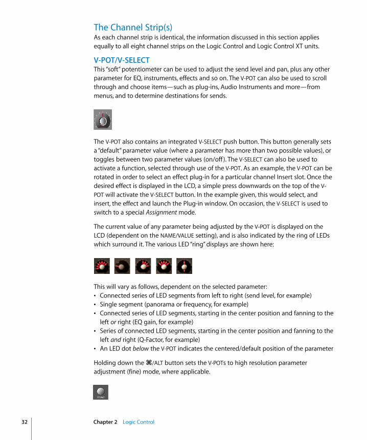
The current value of any parameter being adjusted by the V-POT is displayed on the LCD (dependent on the NAME/VALUE setting), and is also indicated by the ring of LEDs which surround it. The various LED “ring” displays are shown here:
This will vary as follows, dependent on the selected parameter:• Connected series of LED segments from left to right (send level, for example)• Single segment (panorama or frequency, for example)• Connected series of LED segments, starting in the center position and fanning to the
left or right (EQ gain, for example)• Series of connected LED segments, starting in the center position and fanning to the
left and right (Q-Factor, for example)• An LED dot below the V-POT indicates the centered/default position of the parameter
Holding down the C/ALT button sets the V-POTs to high resolution parameter adjustment (fine) mode, where applicable.
Chapter 2 Logic Control

Holding down the OPTION button, and turning the V-POT, toggles between the minimum/maximum parameter value.
Rec/Rdy (Record/Ready) ButtonThis button arms or disables the channel for recording. Each channel features an independent Rec/Rdy LED which is lit when a track is armed for recording.
Holding down the OPTION button, while pressing any channel’s REC/RDY button will disarm all tracks.
In Global View, if you arm an audio channel which is currently not used by any track in the song, and then start recording, you will be asked if you want to create a new track with this audio channel in the current recording folder.
Signal LEDIndicates the presence of any outgoing MIDI or audio signal. When recording, the presence of an incoming signal will be indicated.
SOLO ButtonFor isolating a channel’s signal. Each channel features an independent Solo LED which illuminates when a track is soloed. The Rude Solo LED—just to the right of the Position/Time Display LED—also illuminates whenever any track is soloed.
Holding down the OPTION button, while pressing any channel’s SOLO button will disable solo for all tracks.
In the Send Destination/Level views (see the Send Assignment Modes section, from page 41 onwards), the SOLO button controls the Pre/Post mode selection—in both Multi Channel and Channel Strip views.
Chapter 2 Logic Control 33

34
MUTE ButtonUsed to defeat the track’s signal. Each channel features an independent Mute LED which illuminates when a track is muted.
Holding down the OPTION button, while pressing any MUTE button will unmute all tracks.
In the EQ Frequency/Gain and Send Destination/Level views, the MUTE button controls the EQ bypass or Send mute function. This affects both Multi Channel and Channel Strip views.
SELECT ButtonThis button is used to select a channel for channel-based editing or assignment commands. Each channel features an independent SELECT LED which illuminates when a track is selected.
When holding down the SHIFT button, pressing any channel SELECT button will set the track’s volume to unity level (0 dB).
While holding down SHIFT, a SELECT button’s LED indicates if the track’s volume is set to 0 dB.
When holding down the OPTION button, pressing any channel SELECT button will create a new track (assigned to the same instrument of the selected track), and switch to Arrange View.
When holding down the SHIFT and OPTION buttons, pressing any channel SELECT button will create a new track (with the next instrument, following the selected track), and switch to Arrange View.
Chapter 2 Logic Control
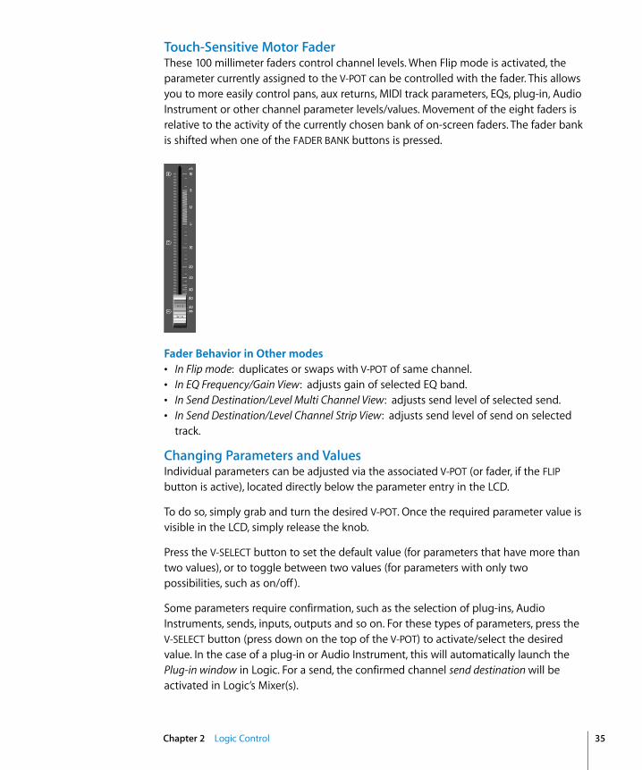
Touch-Sensitive Motor Fader These 100 millimeter faders control channel levels. When Flip mode is activated, the parameter currently assigned to the V-POT can be controlled with the fader. This allows you to more easily control pans, aux returns, MIDI track parameters, EQs, plug-in, Audio Instrument or other channel parameter levels/values. Movement of the eight faders is relative to the activity of the currently chosen bank of on-screen faders. The fader bank is shifted when one of the FADER BANK buttons is pressed.
Fader Behavior in Other modes• In Flip mode: duplicates or swaps with V-POT of same channel.• In EQ Frequency/Gain View: adjusts gain of selected EQ band.• In Send Destination/Level Multi Channel View: adjusts send level of selected send.• In Send Destination/Level Channel Strip View: adjusts send level of send on selected
track.
Changing Parameters and ValuesIndividual parameters can be adjusted via the associated V-POT (or fader, if the FLIP button is active), located directly below the parameter entry in the LCD.
To do so, simply grab and turn the desired V-POT. Once the required parameter value is visible in the LCD, simply release the knob.
Press the V-SELECT button to set the default value (for parameters that have more than two values), or to toggle between two values (for parameters with only two possibilities, such as on/off ).
Some parameters require confirmation, such as the selection of plug-ins, Audio Instruments, sends, inputs, outputs and so on. For these types of parameters, press the V-SELECT button (press down on the top of the V-POT) to activate/select the desired value. In the case of a plug-in or Audio Instrument, this will automatically launch the Plug-in window in Logic. For a send, the confirmed channel send destination will be activated in Logic’s Mixer(s).
Chapter 2 Logic Control 35
36
When a value has been pre-selected, but not confirmed/instantiated (such as send destination, plug-in insertion and so on) the value will flash until the V-SELECT button is pressed.
An exponential increase in value changes will occur as a V-POT is rotated more quickly.
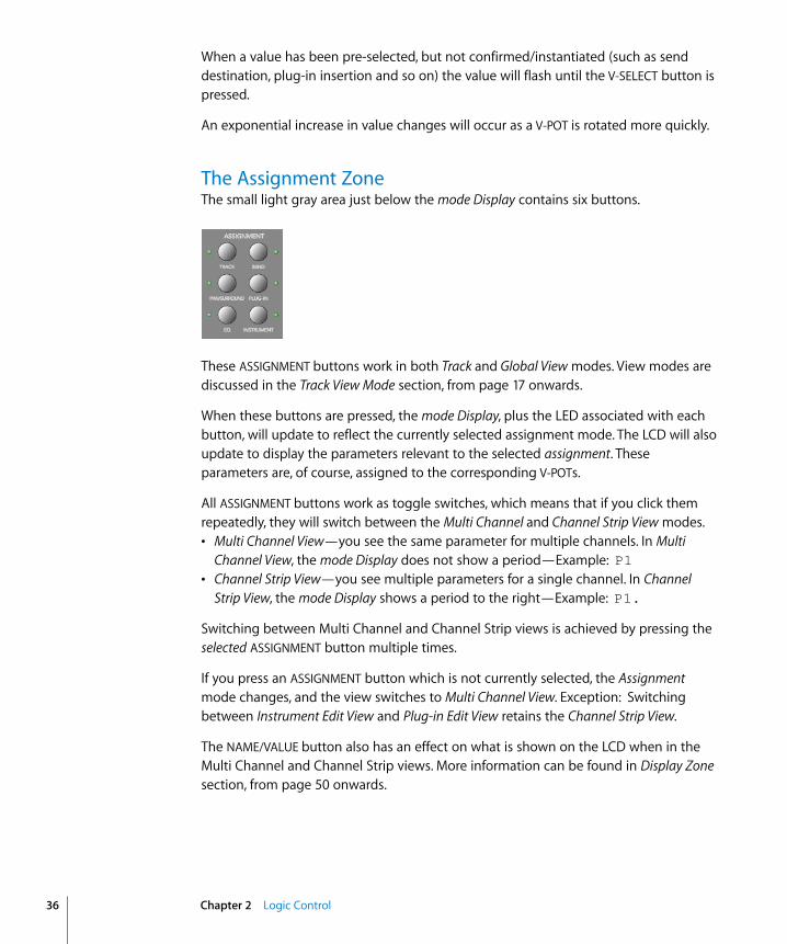
The Assignment ZoneThe small light gray area just below the mode Display contains six buttons.
These ASSIGNMENT buttons work in both Track and Global View modes. View modes are discussed in the Track View Mode section, from page 17 onwards.
When these buttons are pressed, the mode Display, plus the LED associated with each button, will update to reflect the currently selected assignment mode. The LCD will also update to display the parameters relevant to the selected assignment. These parameters are, of course, assigned to the corresponding V-POTs.
All ASSIGNMENT buttons work as toggle switches, which means that if you click them repeatedly, they will switch between the Multi Channel and Channel Strip View modes. • Multi Channel View—you see the same parameter for multiple channels. In Multi
Channel View, the mode Display does not show a period—Example: P1• Channel Strip View—you see multiple parameters for a single channel. In Channel
Strip View, the mode Display shows a period to the right—Example: P1.
Switching between Multi Channel and Channel Strip views is achieved by pressing the selected ASSIGNMENT button multiple times.
If you press an ASSIGNMENT button which is not currently selected, the Assignment mode changes, and the view switches to Multi Channel View. Exception: Switching between Instrument Edit View and Plug-in Edit View retains the Channel Strip View.
The NAME/VALUE button also has an effect on what is shown on the LCD when in the Multi Channel and Channel Strip views. More information can be found in Display Zone section, from page 50 onwards.
Chapter 2 Logic Control

Track Assignment ModesThe TRACK button selects Assignment modes which allow the editing of a number of global track parameters. It toggles between all displayed channels and the individual parameters of the selected channel (Track Multi Channel View or Track Channel Strip View). The parameters in Track Multi Channel View include: Volume, Pan, Track mode,Track Input, Track Output and Automation. In Track Channel Strip View you will see an overview of the most important track parameters: Volume, Pan, Instrument, Insert 1, Insert 2, Send 1 Level, Send 2 Level and Send 3 Level.
Track Multi Channel ViewTrack Multi Channel View allows you to edit a single “global” track parameter for all tracks: Volume, Pan, Track mode, Input, Output or Automation. The parameter being edited will be displayed briefly when switching to this mode.• The mode Display will show tr (for “Track”).• The upper LCD row shows track names.
Pressing NAME/VALUE toggles the display mode to show parameter values in the lower row:
As these display variants can be toggled in all Multi Channel Strip Views, the following will only show displays in Value mode.
• Turning the V-POTs changes the associated track parameter.• Pressing a V-SELECT sets the parameter to its default value.• CURSOR LEFT/RIGHT buttons switch to the next or previous track parameter. The
selected parameter will be displayed briefly in the upper LCD row.
Channel Strip ViewTrack Channel Strip View allows you to edit all parameters listed above, for the selected track.• The mode Display will show tr. (track channel strip).• The upper LCD row shows the name of the track and “Track parameters.”
Audio1 Audio2 Audio3 Audio4 Audio5 Audio6 Audio7 Audio8Volume Volume Volume Volume Volume Volume Volume Volume
Audio1 Audio2 Audio3 Audio4 Audio5 Audio6 Audio7 Audio8+0.1dB -1.8dB +01.dB -30.0 +0.0dB -50.2 -24.7 -1.2dB
Track 1 "Audio 1" Track parametersVolume Pan Inst Ins.1 Ins.2 Send 1 Send 2 Send 3
Chapter 2 Logic Control 37

38
Pressing
NAME/VALUE
toggles the display mode to show parameter names in the upper row and parameter values in the lower row:
As these display variants can be toggled in all
Channel Strip Views
, the following will only show displays in
Value
mode.
•
V-POT/V-SELECT 1
—edits
Volume
. The lower LCD row shows the current track volumes, either in dB or numeric format, depending on the settings of the underlying Environment Objects.
•
V-POT/V-SELECT 2
—edits
Pan
position. The lower LCD row shows the current track pan value, ranging from minus
64
to plus
63
. A value of
0
is the centered position.
•
V-POT 3
—selects the
Instrument
of Audio Instrument tracks. Confirm with
V-SELECT 3
.
•
V-POT/V-SELECT 4
and
5
—selects the
Plug-in
used in Insert slots 1 and 2 (on Audio and Audio Instrument tracks). Confirm with
V-SELECT
.
•
V-POT/V-SELECT 6
to
8
—edits the
Send Level
of Sends 1 to 3.
Holding SHIFT while pressing one of the MUTE or
V-SELECT
buttons toggles mute or bypass:
•
1 and 2—toggles the track’s Mute button.• 3—toggles Mute of the Audio Instrument used on the track.• 4 and 5—toggles Bypass of plug-ins used in Insert slots 1 and 2 (of Audio and Audio
Instrument tracks).• 6 to 8—toggles Mute of Sends 1 to 3.
Shortcuts MenuHolding down the TRACK button accesses a further sub-menu in the LCD.
• The mode Display will show t_ (Track)• V-SELECT 1 or F1—switches to Track Multi Channel View and selects Volume.
• The LCD’s lower line shows the current volume of the tracks, in dB or numerically, depending on the setting of the underlying Environment Object.
• Turning a V-POT changes the volume.• pressing a V-SELECT sets the volume to the default value.
• V-SELECT 2 or F2—switches to Track Multi Channel View and selects Pan. • V-SELECT 3 or F3—switches to Track Multi Channel View and selects Track mode.• V-SELECT 4 or F4—switches to Track Multi Channel View and selects Input.• V-SELECT 5 or F5—switches to Track Multi Channel View and selects Output.• V-SELECT 6 or F6 —switches to Track Multi Channel View and selects Automation mode.• V-SELECT 7 or F7—switches to Track Multi Channel View and displays the automation
parameter selected in the Arrange window. Also switches to Arrange View.
Volume Pan Inst Ins.1 Ins.2 Send 1 Send 2 Send 3+0.5dB 0 ES2 Dstrtn AutFlt -54.0 -27.0 -oo dB
Volume Pan TrkMod Input Output Auto Setup
Chapter 2 Logic Control
•
V-SELECT 8
or
F8
—switches to
Track Setup Channel Strip View
(see below).
Track Setup Channel Strip View
In this mode, rarely used parameters can be edited for the selected track.
•
V-POT/V-SELECT 1
—edits
Track mode
(mono, stereo, left, right).
•
V-POT/V-SELECT 3
—selects the
Track Input
. Confirm with
V-SELECT 6
.
•
V-POT/V-SELECT 4
—selects the
Track Output
. Confirm with
V-SELECT 7
.
•
V-POT/V-SELECT 5
—edits
Automation mode
.
•
V-POT/V-SELECT 6
—edits
Track Group Membership
. You can only choose one group or “Off”. To make a track a member of multiple groups, use Group Edit mode (see below).
Pan Assignment Modes
Briefly pressing the
PAN/SURROUND
button toggles between
Pan Multi Channel
and
Pan Channel Strip View
.
Multi Channel View
Pan Multi Channel view allows you to edit the pan parameter on all tracks
•
The
mode Display
will show Pn (Pan).• The upper LCD row shows track names.• Turning the V-POTs changes the pan parameter.• Pressing a V-SELECT sets the pan parameter to its default value.
Channel Strip ViewPan Channel Strip View allows you to edit the pan parameter for the selected track.• The mode Display will show Pn. (Pan/Surround channel strip).• The upper LCD row shows the name of the track and “Pan”.
• V-POT/V-SELECT 1—edits pan.
Track 1 "Audio 1" Pan/SurroundSrrAng SrrDvr SrrLFE mode
Chapter 2 Logic Control 39
40
EQ Assignment Modes
Briefly pressing the
EQ
button toggles between
EQ Multi Channel View
or
EQ Channel Strip View
.
Note:
If no Channel EQ is present on the selected track, it will be inserted automatically when the EQ Channel Strip View is entered.
Multi Channel View
EQ Multi Channel View
allows you to edit one equalizer parameter for all tracks:
Frequency
,
Gain
,
Q
or
EQ bypass
. The EQ band number, and parameter being edited will be displayed for one second when switching to this mode.
•
The
mode Display
will show
E1
to
E8
, dependent on the selected EQ band number.
•
The upper LCD row shows track names.
•
Turning the
V-POT
s changes the EQ parameter.
•
Pressing a
V-SELECT
sets the parameter to its default value.
•
CURSOR UP/DOWN
switches to the next or previous EQ band.
•
CURSOR LEFT/RIGHT
switches to the next or previous EQ parameter. The selected parameter will be displayed briefly in the upper LCD row.
•
Pressing a MUTE button while the SHIFT button is held down toggles the current EQ band’s Bypass status.
•
When Flip mode is enabled, the
MUTE
buttons display and edit the current EQ band’s Bypass status.
Channel Strip View
EQ Channel Strip view allows you to edit all EQ parameters—in all bands—for the selected track.
•
The
mode Display
will show
EQ.
(EQ channel strip).
•
The upper LCD row shows the name of the track, “EQs”, the page number and total number of pages—Example: “Page 1/2”.
•
V-POT/V-SELECT 1
—edits the Frequency of odd-numbered EQ bands.
•
V-POT/V-SELECT 2
—edits Gain of odd-numbered EQ bands.
• V-POT/V-SELECT 3 —edits Q-Factor of odd-numbered EQ bands.
•
V-POT/V-SELECT 4
—edits Bypass
of odd-numbered EQ bands.
•
V-POT/V-SELECT 5
—edits the Frequency of even-numbered EQ bands.
•
V-POT/V-SELECT 6
—edits Gain of even-numbered EQ bands.
•
V-POT/V-SELECT 7
—edits Q-Factor of even-numbered EQ bands.
•
V-POT/V-SELECT 8
—edits Bypass
of even-numbered EQ bands.
•
CURSOR LEFT/RIGHT
switches to the next or previous EQ band. The number of EQ bands displayed on the LCD depends on the number of Logic Control (XT) units (two EQ bands are shown per unit) available.
Chapter 2 Logic Control

Alternate Mode OptionsHolding down the EQ button accesses a further sub-menu in the LCD:• The mode Display shows E_ or E_., dependent on whether you were in EQ Multi
Channel or EQ Channel Strip View.• V-SELECT 1 or F1—switches to EQ Multi Channel View and selects Frequency.• V-SELECT 2 or F2—switches to EQ Multi Channel View and selects Gain• V-SELECT 3 or F3—switches to EQ Multi Channel View and selects Q.• V-SELECT 4 or F4—switches to EQ Multi Channel View and selects Bypass.• V-SELECT 6 or F6—switches to EQ Channel Strip View.• V-SELECT 7 or F7—switches to Frequency/Gain Multi Channel View. In this mode you
can edit the Frequency and Gain parameters of a specific EQ band (1 to 4) for all tracks.• the mode Display will show F1 to F8, depending on the selected EQ band.• the upper LCD row shows track names.• the lower LCD row shows the Frequency of the selected EQ.• turning a V-POT changes EQ Frequency.• pressing a V-SELECT sets the EQ Frequency to its default value.• use the MUTE buttons to Bypass the EQ.• use the faders adjust the EQ Gain.
• V-SELECT 8 or F8—switches to Frequency/Gain Channel Strip View. In this mode you can edit the Frequency and Gain parameters for all EQ bands of the selected track. Each pair of channel strips corresponds to one of the EQ bands.• the mode Display will show FG.• V-POTs 1 to 8 control the Frequency of EQ bands 1 to 8.• MUTE buttons 1 to 8 control the Bypass of EQ bands 1 to 8.• FADERs 1 to 8 control the Gain of EQ bands 1 to 8.
Note that the faders form a frequency response curve in this mode, if the EQ bands have ascending frequency values.
You can edit another track’s EQ, without leaving this view mode, by simply selecting the track.
Send Assignment ModesBriefly pressing the SEND button toggles between Send Multi Channel or Send Channel Strip View.
Multi Channel ViewSend Multi Channel View allows you to edit one Send parameter for all tracks: Destination, Level, Position and Mute. The Send slot number, and parameter being edited will be displayed for one second when switching to this mode.• The mode Display will show S1 to S8, depending on the selected Send slot.• The upper LCD row shows track names.• Turning the V-POTs changes the Send parameter.
Chapter 2 Logic Control 41
42
• Pressing a V-SELECT confirms the pre-selected Send Destination and sets the other send parameters to their defaults.
• CURSOR UP/DOWN switches to the next or previous Send slot.• CURSOR LEFT/RIGHT switches to the next or previous Send parameter. The selected
parameter will be displayed briefly in the upper LCD row.
• Pressing a MUTE button while the SHIFT button is held toggles the current Send’s Mute status.
• When Flip mode is enabled, the MUTE buttons display and edit the current Send’s Mute status.
Note: Ensure that the ZOOM button isn’t active when using the CURSOR keys.
Channel Strip ViewSend Channel Strip View allows you to edit all Send parameters for the selected track.• The mode Display will show SE. (Send channel strip).• The upper LCD row shows the name of the track, “Sends”, the page number and total
number of pages—Example: “Page 1/4”
• V-POT/V-SELECT 1—edits Destination of odd-numbered Sends.• V-POT/V-SELECT 2—edits Level of odd-numbered Sends.• V-POT/V-SELECT 3—edits Position (pre/post) of odd-numbered Sends.• V-POT/V-SELECT 4—edits Mute of odd-numbered Sends.• V-POT/V-SELECT 5—edits Destination of even-numbered Sends.• V-POT/V-SELECT 6—edits Level of even-numbered Sends.• V-POT/V-SELECT 7—edits Position (pre/post) of even-numbered Sends.• V-POT/V-SELECT 8—edits Mute of even-numbered Sends.• The horizontal CURSOR buttons shift between pages. The number of Sends displayed
simultaneously is dependent on the number of Logic Control XTs you have.
Alternate Edit Mode OptionsHolding down the SEND button accesses a further sub-menu in the LCD:• The mode Display shows S_ or S_., depending on whether you were in Send Multi
Channel or Send Channel Strip View.
Track 1 "Audio 1" Sends Page 1/2Snd3Ds Send 3 Snd3Ps Snd3Mt Snd4Ds Send 4 Snd4Ps Snd4Mt
Dest Pos Level Mute CStrip CSt2 Ds/LvM Ds/LvC
Chapter 2 Logic Control

•
V-SELECT 1
or
F1
—switches to
Send Multi Channel View
and selects Destination.
•
V-SELECT 2
or
F2
—switches to
Send Multi Channel View
and selects Send Level.
•
V-SELECT 3
or
F3
—switches to
Send Multi Channel View
and selects Position.
•
V-SELECT 4
or
F4
—switches to
Send Multi Channel View
and selects Mute.
•
V-SELECT 5
or
F5
—switches to
Send Channel Strip View.
•
V-SELECT 6
or
F6
—switches to
Send Channel Strip 2 View
:This mode is similar to
Send Channel Strip View
, but parameters are arranged in a slightly different way. You can control one parameter of all
Send
slots for the selected track.
•
The
mode Display will show SE. (Send channel strip).• The upper LCD row shows the name of the track, “Sends”, the page number and
total number of pages.
• V-POT/V-SELECT 1 to 8—edits the displayed parameter.• The horizontal CURSOR buttons shift between pages. The number of parameters
displayed simultaneously is dependent on the number of Logic Control XTs you have.
• V-SELECT 7 or F7—switches to Destination/Level Multi Channel View:In this mode, you can control one Send slot for all tracks. Each channel strip corresponds to the track shown in the upper LCD row.
• the mode Display will show d1 to d8, depending on the selected Send.• the upper LCD row shows track names.• the lower LCD row shows the destination of the selected Send.• turning a V-POT pre-selects the Send Destination.• pressing a V-SELECT confirms the pre-selected Send Destination.• the SOLO buttons edit Send Position— a lit SOLO LED indicates Pre Fader mode.• the MUTE buttons edit Send Mute.• the faders edit Send Level.
• V-SELECT 8 or F8—switches to Destination/Level Channel Strip View:You can control all Send slots for the selected track in this mode. Each channel strip corresponds to the (embossed) Send number shown below the LCD.
• the mode Display will show dL.• turning a V-POT pre-selects the corresponding Send Destination.• pressing a V-SELECT confirms a preselected Send Destination.• the SOLO buttons edit Send Position—a lit SOLO LED indicates Pre Fader mode.• the MUTE buttons edit Send Mute.
Track 1 "Audio 1" Sends Page 1/2Snd1Ds Snd2Ds Snd3Ds Snd4Ds Snd5Ds Snd6Ds Snd7Ds Snd7Ds
Chapter 2 Logic Control 43
44
•
the faders edit Send Gain.
If one or more Sends are activated on multiple channels, you can switch between them in the
Channel Strip View
s by simply pressing the SELECT button for the desired channel.
Plug-in Assignment Modes
Pressing
PLUG-IN
toggles between
Plug-in Multi Channel
or
Plug-in Channel Strip View
.
Note:
There is one exception to this behavior: if you are in
Instrument Edit View
, pressing this button switches to
Plug-in Edit View
.
Multi Channel View
This mode shows the plug-ins associated with a particular Insert slot for all channels.
•
The
mode Display
will show
P1
to P9, or simply 10 to 16, dependent on the selected Plug-in Insert slot number. Note that if an Audio Instrument channel is selected, the display will show P1 to P5.
• The upper LCD row shows track names.• The lower LCD row shows the currently selected plug-in for this Insert slot. Muted
plug-ins are shown with an asterisk * that precedes the plug-in name.• Turning the V-POTs pre-selects a new plug-in. The plug-in name flashes until
confirmed with the V-SELECT.• Turning another channel’s V-POT will cancel any earlier pre-selection, and will start
pre-selection on the newly selected track.• Pressing a V-SELECT:
• confirms/activates the pre-selected plug-in (assuming that you’ve made your pre-selection by turning the V-POT).
• opens a Plug-in window, if none are opened. If a Plug-in window is open, and Link mode is enabled, the selection of another plug-in will replace the existing Plug-in window.
• switches to Plug-in Edit View.• The CURSOR UP/DOWN buttons change the currently displayed plug-in Insert slot (1 to
5).• Pressing a V-SELECT or the MUTE button while the SHIFT button is held down will
mute/unmute the plug-in.
To remove a plug-in:1 Pre-select the “--” value (by turning the V-POT fully counter-clockwise)
2 Press the V-SELECT of the appropriate Insert slot.
Logic Control will not switch to Plug-in Edit view, and no Plug-in window will be launched. If one was previously opened, it will be closed (if Link mode is inactive).
Chapter 2 Logic Control

Channel Strip ViewThis mode shows the plug-ins associated with all Insert slots for the selected channel.• The mode Display will show PL.• The upper LCD row shows Ins1Pl through Ins8Pl• The lower LCD row shows the plug-in which is currently selected for this insert slot.
Muted plug-ins are indicated by an asterisk *, which precedes the plug-in name.• Turning the V-POTs pre-selects a new plug-in. The plug-in name flashes until
activated.• Turning another channel’s V-POT will cancel any previous pre-selection and will start
pre-selection on the newly selected track.• Pressing a V-SELECT:
• activates the pre-selected plug-in (assuming that you’ve made your pre-selection by turning the V-POT).
• opens a Plug-in window if none are opened (if a Plug-in window is open and Link mode is enabled, the selection of another plug-in will replace the existing plug-in).
• switches to Plug-in Edit View.• Pressing a V-SELECT while the SHIFT button is held will mute/unmute the plug-in.
To remove a plug-in: 1 Pre-select the “--” value (by turning the V-POT fully counter-clockwise).
2 Press the V-SELECT linked to the appropriate Insert slot.
Logic Control will not switch to Plug-in Edit view, and no Plug-in window will be launched. If one was previously opened, it will be closed (if Link mode is inactive).
Plug-in Edit View• The mode Display will show P1. to P8., depending on the number of the selected
plug-in Insert slot.• Dependent on the NAME/VALUE button, the LCD display will change in the following
ways between the two modes:• Name: The upper LCD row shows the track’s name, insert number, plug-in name,
current parameter page and total number of parameter pages. The lower LCD row shows the name of the parameter which can be edited via the V-POT located below.
• Value: The upper LCD row shows the name of the parameter which can be edited via the V-POT positioned below.The lower LCD row shows the current value of the parameter edited with the V-POT. If there is sufficient onscreen space, the unit type will be added—Example: Hz.
• Turning the V-POTs changes parameters.• Pressing a V-SELECT sets the parameter to its default value, except where the
parameter only has two values (on/off, for example). In this case, pressing the V-SELECT toggles between these values.
Chapter 2 Logic Control 45
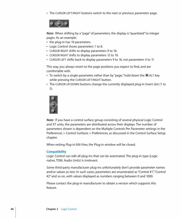
46
• The CURSOR LEFT/RIGHT buttons switch to the next or previous parameter page.
Note: When shifting by a “page” of parameters, the display is “quantized” to integer pages. As an example:• the plug-in has 19 parameters.• Logic Control shows parameters 1 to 8.• CURSOR RIGHT shifts to display parameters 9 to 16.• CURSOR RIGHT shifts to display parameters 12 to 19.• CURSOR LEFT shifts back to display parameters 9 to 16, not parameters 4 to 11.
This way, you always revert to the page positions you expect to find, and are comfortable with.• To switch by a single parameter, rather than by “page,” hold down the C/ALT key
while pressing the CURSOR LEFT/RIGHT button.• The CURSOR UP/DOWN buttons change the currently displayed plug-in Insert slot (1 to
5).
Note: If you have a control surface group consisting of several physical Logic Control and XT units, the parameters are distributed across their displays. The number of parameters shown is dependent on the Multiple Controls Per Parameter settings in the Preferences > Control Surfaces > Preferences, as discussed in the Control Surface Setup chapter.
When exiting Plug-in Edit View, the Plug-in window will be closed.
CompatibilityLogic Control can edit all plug-ins that can be automated. The plug-in type (Logic native, TDM, Audio Units) is irrelevant.
Some third-party manufacturer plug-ins unfortunately don’t provide parameter names and/or values as text. In such cases, parameters are enumerated as “Control #1”, “Control #2” and so on, with values displayed as numbers ranging between 0 and 1000.
Please contact the plug-in manufacturer to obtain a version which supports this feature.
Chapter 2 Logic Control
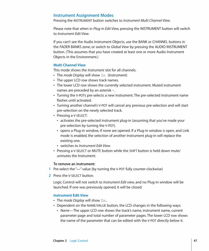
Instrument Assignment ModesPressing the INSTRUMENT button switches to Instrument Multi Channel View.
Please note that when in Plug-in Edit View, pressing the INSTRUMENT button will switch to Instrument Edit View.
If you can’t see the Audio Instrument Objects, use the BANK or CHANNEL buttons in the FADER BANKS zone, or switch to Global View by pressing the AUDIO INSTRUMENT button. (This assumes that you have created at least one or more Audio Instrument Objects in the Environment.)
Multi Channel ViewThis mode shows the Instrument slot for all channels. • The mode Display will show In (Instrument)• The upper LCD row shows track names.• The lower LCD row shows the currently selected instrument. Muted instrument
names are preceded by an asterisk *.• Turning the V-POTs pre-selects a new instrument. The pre-selected instrument name
flashes until activated.• Turning another channel’s V-POT will cancel any previous pre-selection and will start
pre-selection on the newly selected track.• Pressing a V-SELECT:
• activates the pre-selected instrument plug-in (assuming that you’ve made your pre-selection by turning the V-POT).
• opens a Plug-in window, if none are opened. If a Plug-in window is open, and Link mode is enabled, the selection of another Instrument plug-in will replace the existing one.
• switches to Instrument Edit View.• Pressing a V-SELECT or MUTE button while the SHIFT button is held down mute/
unmutes the Instrument.
To remove an instrument: 1 Pre-select the “--” value (by turning the V-POT fully counter-clockwise)
2 Press the V-SELECT button.
Logic Control will not switch to Instrument Edit view, and no Plug-in window will be launched. If one was previously opened, it will be closed.
Instrument Edit View• The mode Display will show In.• Dependent on the NAME/VALUE button, the LCD changes in the following ways:
• Name—The upper LCD row shows the track’s name, instrument name, current parameter page and total number of parameter pages. The lower LCD row shows the name of the parameter that can be edited with the V-POT directly below it.
Chapter 2 Logic Control 47
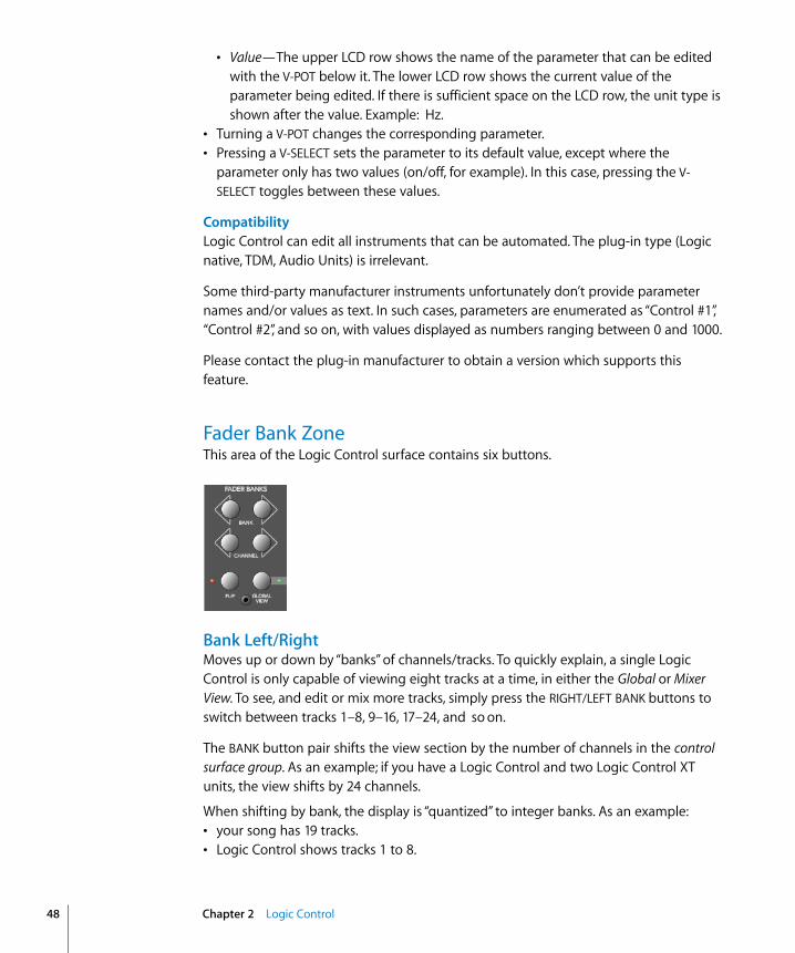
48
• Value—The upper LCD row shows the name of the parameter that can be edited with the V-POT below it. The lower LCD row shows the current value of the parameter being edited. If there is sufficient space on the LCD row, the unit type is shown after the value. Example: Hz.
• Turning a V-POT changes the corresponding parameter.• Pressing a V-SELECT sets the parameter to its default value, except where the
parameter only has two values (on/off, for example). In this case, pressing the V-SELECT toggles between these values.
CompatibilityLogic Control can edit all instruments that can be automated. The plug-in type (Logic native, TDM, Audio Units) is irrelevant.
Some third-party manufacturer instruments unfortunately don’t provide parameter names and/or values as text. In such cases, parameters are enumerated as “Control #1”, “Control #2”, and so on, with values displayed as numbers ranging between 0 and 1000.
Please contact the plug-in manufacturer to obtain a version which supports this feature.
Fader Bank ZoneThis area of the Logic Control surface contains six buttons.
Bank Left/RightMoves up or down by “banks” of channels/tracks. To quickly explain, a single Logic Control is only capable of viewing eight tracks at a time, in either the Global or Mixer View. To see, and edit or mix more tracks, simply press the RIGHT/LEFT BANK buttons to switch between tracks 1–8, 9–16, 17–24, and so on.
The BANK button pair shifts the view section by the number of channels in the control surface group. As an example; if you have a Logic Control and two Logic Control XT units, the view shifts by 24 channels.
When shifting by bank, the display is “quantized” to integer banks. As an example:• your song has 19 tracks.• Logic Control shows tracks 1 to 8.
Chapter 2 Logic Control

• BANK Right shifts to tracks 9 through 16.• BANK Right shifts to tracks 12 through 19.• BANK Left shifts back to tracks 9 through 16, not tracks 4 to 11.
This way, you always revert to the bank positions you expect, and are used to.
Channel Left/RightAs per the BANK buttons, but moves up or down in increments of a single channel.
Notes on Fader Bank EditingWhen holding down the OPTION button, pressing the BANK LEFT or CHANNEL LEFT button jumps to the first, and pressing the BANK RIGHT or CHANNEL RIGHT button jumps to the last, tracks in the song. As an example in a 64 track song, tracks 1 through 8 or tracks 57 through 64.
The fader bank offset is independently memorized for Global views where one track class is displayed (MIDI, Inputs,Audio Tracks, Instruments, Auxes, Busses, Outputs). There is also a separate fader bank offset memory location for combinations of multiple track types. This feature allows you to scroll to audio tracks 2 through 9 in Global Audio Track view, and then scroll to instruments 5 through 12 in Global Instruments view. You can switch between these views without losing the fader bank offset.
FlipThe FLIP button enables/disables the following Flip, Swap or Zero modes:• If the LED beside the FLIP button is off, Flip mode is off. The faders control volume.• Pressing the FLIP button enables Flip mode (the LED is lit): in this mode, the current
assignments of the eight V-POTs are mirrored by the eight channel faders. Pressing the FLIP button a second time disables Flip mode.
Turning a V-POT in this mode will also move the corresponding fader.• Pressing the FLIP button while the SHIFT button is held enables Swap mode (the LED
will flash): in this mode, the encoder assignments are swapped with the fader assignments. Pressing SHIFT and FLIP again disables Swap mode. As the LCD’s lower row shows the current value of the encoders, it will display volumes when in this mode.
• Pressing FLIP without SHIFT held reverts to Flip mode.• Pressing CONTROL and FLIP switches to Zero mode. Pressing CONTROL and FLIP a
second time disables Zero mode. In this mode, the faders are set to zero and don’t move. This is useful for acoustic/microphone recordings if Logic Control is located in the recording booth, and you don’t want to hear/capture any motor noise.
Both Flip and Swap modes work in all view modes.
Chapter 2 Logic Control 49
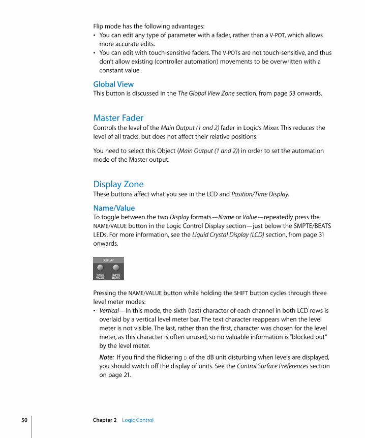
50
Flip mode has the following advantages:• You can edit any type of parameter with a fader, rather than a V-POT, which allows
more accurate edits.• You can edit with touch-sensitive faders. The V-POTs are not touch-sensitive, and thus
don’t allow existing (controller automation) movements to be overwritten with a constant value.
Global ViewThis button is discussed in the The Global View Zone section, from page 53 onwards.
Master FaderControls the level of the Main Output (1 and 2) fader in Logic’s Mixer. This reduces the level of all tracks, but does not affect their relative positions.
You need to select this Object (Main Output (1 and 2)) in order to set the automation mode of the Master output.
Display ZoneThese buttons affect what you see in the LCD and Position/Time Display.
Name/ValueTo toggle between the two Display formats—Name or Value—repeatedly press the NAME/VALUE button in the Logic Control Display section—just below the SMPTE/BEATS LEDs. For more information, see the Liquid Crystal Display (LCD) section, from page 31 onwards.
Pressing the NAME/VALUE button while holding the SHIFT button cycles through three level meter modes:• Vertical—In this mode, the sixth (last) character of each channel in both LCD rows is
overlaid by a vertical level meter bar. The text character reappears when the level meter is not visible. The last, rather than the first, character was chosen for the level meter, as this character is often unused, so no valuable information is “blocked out” by the level meter.
Note: If you find the flickering D of the dB unit disturbing when levels are displayed, you should switch off the display of units. See the Control Surface Preferences section on page 21.
Chapter 2 Logic Control
• Horizontal—with Peak Hold. In this mode, the second row is replaced by horizontal level meter bars. Peak Hold is shown as a hollow box which disappears after three seconds. Overload (clipping) is displayed as an asterisk. It remains on the LCD until cleared (see below).
• Off—In this mode, no level meters are displayed in the LCD.
In all three modes, the SIGNAL LEDs function as per usual, indicating the presence of a signal.
Note: The MIDI bandwidth required for the display of level meters is the same in all three modes—and is very low. The Position/Time Display updates require much more MIDI bandwidth than the level meters.
Pressing the NAME/VALUE button, while holding the CONTROL button, clears overload (clipping) in both Logic’s Environment/Track Mixer, and the horizontal level meters on the Logic Control.
Pressing the NAME/VALUE button, while holding the C/ALT button, enters Control Surface Group Settings mode. This mode enables you to edit several control surface group settings, some of which are not accessible with a single button:• V-POT/V-SELECT 5 (label “TrkNam”)—sets track name display format
“Name”—track name only“#:Name”—track number and nameThis parameter can also be toggled with OPTION and NAME/VALUE.
• V-POT/V-SELECT 6 (label “Lock”)—toggles Channel Strip View track lock“Off”—as you are used to: selecting a track also switches the currently edited Channel Strip track.“On”—the currently edited Channel Strip Track is not affected by selecting a track.
When you switch from On to Off, this also updates the Channel Strip track.
To edit another track in Locked mode, first disable Lock, then select the desired track, then re-enable Lock.• V-POT/V-SELECT 7 (label “Disply”)—toggles LCD display format.
“Name”—upper line displays global info, lower line displays parameter names.“Value”—upper line displays parameter names, lower line displays parameter values.This parameter can also be toggled with NAME/VALUE.
• V-POT/V-SELECT 8 (label “Clock”)—toggles Clock display format.“Beats”—clock is displayed in format bars/measures/beats/ticks.“SMPTE”—clock is displayed in SMPTE format.This parameter can also be toggled with SMPTE/BEATS.
Control Surface Group Settings mode can be exited by pressing NAME/VALUE, or by entering one of the Marker modes.
Chapter 2 Logic Control 51

52
SMPTE/BeatsTo toggle between the two Time formats, repeatedly press the SMPTE/BEATS button in the Display section at the top of the Logic Control—just below the SMPTE/BEATS LEDs. For more information, see the Song Position/SMPTE Time Display section on page 31.
The Function Key Zone
The eight Function keys—F1 to F8—are assigned as follows:• F1 to F7 recalls Screensets 1 to 7.• F8 closes the top-most window, with “floating” windows closed first.
With the SHIFT key held down, the Function keys toggle particular windows:• F1—Arrange window• F2—Track Mixer• F3—Event Editor• F4—Score Editor• F5—Hyper Editor• F6—Matrix Editor• F7—Transport window• F8—Audio window
With the C/ALT key held down, the Function keys trigger common key commands:• F1—Cut• F2—Copy• F3—Paste• F4—Clear• F5—Select All• F6—Select All Following• F7—Select Similar Objects• F8—Select Inside Locators
In modal dialogs, the Function keys are equivalent to the computer’s number keys:• F1—1• F2—2• F3—3• F4—4• F5—5• F6—6
Chapter 2 Logic Control

• F7—7• F8—8
The following buttons directly below the Function keys supplement the numeric input functions:• MIDI Tracks button—9• Inputs button—0
In some other “modes,” the Function keys perform other duties, such as shortcuts to markers. Please see the Marker section on page 57. Also see the tables in the Assignment Overview section, from page 64 onwards.
The Global View ZoneThe Global View mode is activated by pressing any of the GLOBAL VIEW buttons. When any is activated, the green LED to the right of the GLOBAL VIEW button will illuminate.
Pressing multiple GLOBAL VIEW buttons simultaneously will display the channels of the selected classes.
To do so:m Hold down any GLOBAL VIEW button, and add or remove other Object classes by
pressing the other desired GLOBAL VIEW buttons.
The display order matches the order of these buttons on the front panel of the Logic Control.
You can select multiple classes by clicking on multiple buttons simultaneously. The OUTPUTS button activates Output Objects.
As an example: To see the busses and the outputs, hold down BUSSES, and then press OUTPUTS.
Chapter 2 Logic Control 53

54
Function Button ZoneThere are three areas in this zone—Modifiers, Automation and Utilities.
Modifier Buttons
The four buttons in this area are similar to those found on your computer keyboard (but are independent from the keyboard modifiers). Many of Logic’s functions behave differently when one or more “modifier” key(s) is pressed, in conjunction with another key or mouse click. This also applies to the Logic Control. All “modified” Logic Control commands are covered in each function’s description.
A generic description of each button follows:• SHIFT—an alternate function/meaning for a button.• OPTION—the function applies to all objects. For relative value changes: the value is
set to the minimum or maximum, depending on whether you increase/decrease it.• C/ALT—fine tuning/variation of the function.
Automation Buttons
The five buttons in this area activate/deactivate the various automation modes of Logic. These work in conjunction with the channel SELECT buttons. Simply choose the channel you wish to automate, select the Automation mode via one of these six buttons, and move the corresponding fader. The modes are outlined below:
• READ/OFF—Pressing this button repeatedly toggles between the “Read” and “Off” automation modes.• Off—Automation is off. The fader will neither send nor receive automation data.
Existing automation data remains untouched. It will still behave as a fader, however, and will adjust the volume or pan position and so on as usual.
Chapter 2 Logic Control

• Read—The fader will read (follow) any existing automation data, but will not write data, regardless of any movements you make with the mouse or external control device.
• TOUCH—Writes new parameter changes when the fader is “touched” or V-POT turned during playback. Any existing track automation data (of the current fader type) will be replaced by new movements as long as the control is active—while the fader is being touched or V-POT is being turned.
• LATCH—Similar to Touch mode, but the control remains activated, even when the fader is no longer being “touched” or V-POT being turned. In other words, following the release of the fader, the current fader value will replace the existing automation data for as long as the sequencer is in playback mode. Press STOP to finish.
• WRITE—Overwrites all existing automation data, or creates new automation data. Only use it if you wish to destroy all existing automation data.
• TRIM—Not currently enabled.
Pressing one of the Automation buttons while holding the OPTION key assigns the selected automation mode for all tracks. When an automation mode has been selected for all tracks, the button’s LED will illuminate whenever the OPTION key is held.
Important: This behavior is slightly different for the “Off” automation mode, when holding down the OPTION button. While doing so, all automation “writing” buttons will be turned off, but this does not necessarily mean that all tracks are actually in Off mode—they could also be in different modes. To ensure that you have set all tracks to Off mode, press READ/OFF twice (its LED goes on, then off ), while holding down the OPTION key.
Utilities ButtonsThe four buttons in this area trigger functions that are often used when working with Logic.
SaveSaves the current song file. When pressed, a file save dialog will open on your computer screen, awaiting input of a filename.
The Logic Control LCD will display There is a file select dialog on the screen and the Position/Time Display will show ALErt. All LEDs are unlit.
Once the file save has been confirmed—in Logic—the Logic Control will return all controls to their status prior to use of the Save command.
Chapter 2 Logic Control 55

56
Once the song has been saved and given a name, you may freely use the SAVE button to save any subsequent changes. This will occur without the alert messages and file save dialog appearing onscreen.
As a general working tip, you should always save your Autoload/Template song under a different name as the first step in any project. If this practice is adhered to, you will be able to simply press the SAVE button on the Logic Control to incrementally save your work.
The SAVE LED illuminates as soon as any save-able change has been made in Logic.
Holding down the OPTION button while pressing SAVE opens the “Save As” file selector box.
UndoPressing the UNDO button undoes the last undo-able editing step. As Logic supports near-unlimited multiple undo/redo, the green UNDO LED does not illuminate to indicate an undo-able step, but rather to indicate that Redo is available. This serves as a warning that performing a reversible editing step would render all Redo steps unavailable.
Holding down the SHIFT button while pressing UNDO performs a “Redo.”
Holding down the OPTION button while pressing UNDO opens the Undo History window.
CancelIf an alert is open on-screen, it triggers the Cancel (or Abort) button. More information on alerts is found in the About Modal Dialogs section on page 27. Pressing the CANCEL button when no alert is opened will launch the Toolbox at the current on-screen position of the mouse cursor. Alternately, it will perform any function currently assigned to the computer keyboard’s Esc key.
If no alert is open, and Logic Control is currently showing the contents of a folder track, use of the CANCEL button exits the folder.
CANCEL also enables you to invalidate a (blinking) parameter value pre-selection.
EnterIf an alert is open, the ENTER button triggers the default button. See the About Modal Dialogs section on page 27 for more information.
If no alert is open, and the selected track is a folder track, the ENTER button opens the folder.
Chapter 2 Logic Control
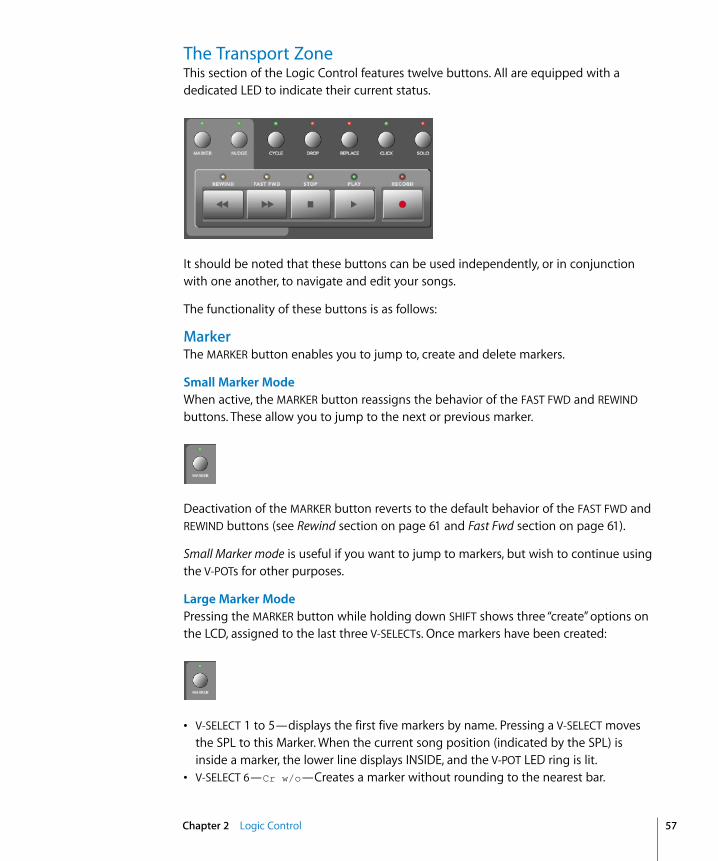
The Transport ZoneThis section of the Logic Control features twelve buttons. All are equipped with a dedicated LED to indicate their current status.
It should be noted that these buttons can be used independently, or in conjunction with one another, to navigate and edit your songs.
The functionality of these buttons is as follows:
MarkerThe MARKER button enables you to jump to, create and delete markers.
Small Marker ModeWhen active, the MARKER button reassigns the behavior of the FAST FWD and REWIND buttons. These allow you to jump to the next or previous marker.
Deactivation of the MARKER button reverts to the default behavior of the FAST FWD and REWIND buttons (see Rewind section on page 61 and Fast Fwd section on page 61).
Small Marker mode is useful if you want to jump to markers, but wish to continue using the V-POTs for other purposes.
Large Marker ModePressing the MARKER button while holding down SHIFT shows three “create” options on the LCD, assigned to the last three V-SELECTs. Once markers have been created:
• V-SELECT 1 to 5—displays the first five markers by name. Pressing a V-SELECT moves the SPL to this Marker. When the current song position (indicated by the SPL) is inside a marker, the lower line displays INSIDE, and the V-POT LED ring is lit.
• V-SELECT 6—Cr w/o—Creates a marker without rounding to the nearest bar.
Chapter 2 Logic Control 57
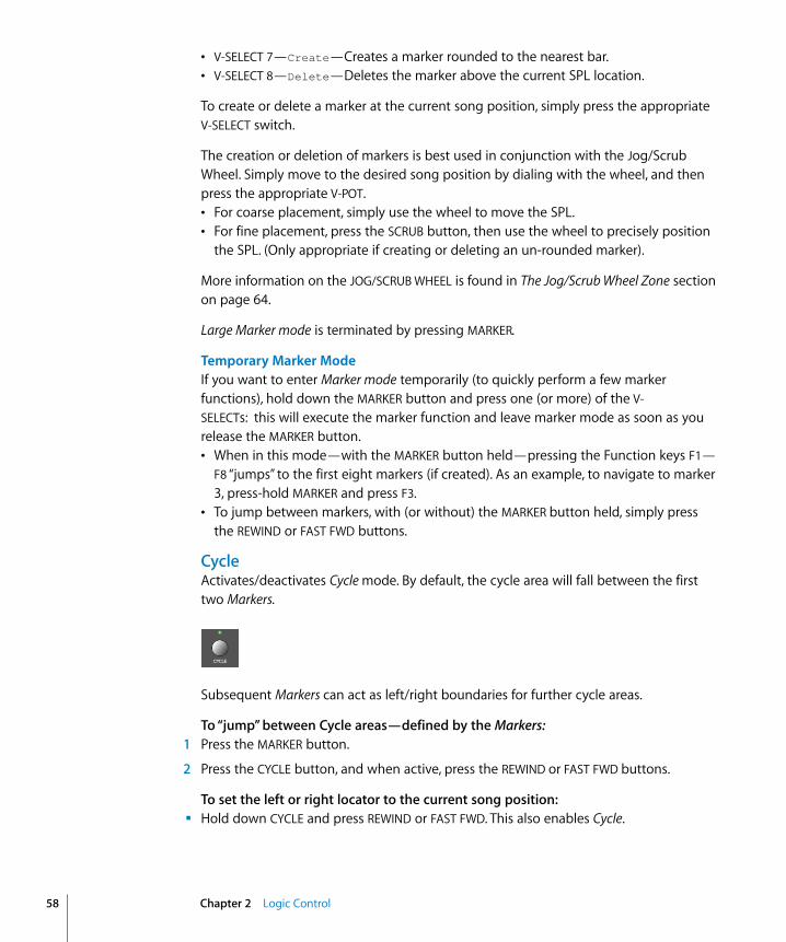
58
• V-SELECT 7—Create—Creates a marker rounded to the nearest bar.• V-SELECT 8—Delete—Deletes the marker above the current SPL location.
To create or delete a marker at the current song position, simply press the appropriate V-SELECT switch.
The creation or deletion of markers is best used in conjunction with the Jog/Scrub Wheel. Simply move to the desired song position by dialing with the wheel, and then press the appropriate V-POT. • For coarse placement, simply use the wheel to move the SPL. • For fine placement, press the SCRUB button, then use the wheel to precisely position
the SPL. (Only appropriate if creating or deleting an un-rounded marker).
More information on the JOG/SCRUB WHEEL is found in The Jog/Scrub Wheel Zone section on page 64.
Large Marker mode is terminated by pressing MARKER.
Temporary Marker ModeIf you want to enter Marker mode temporarily (to quickly perform a few marker functions), hold down the MARKER button and press one (or more) of the V-SELECTs: this will execute the marker function and leave marker mode as soon as you release the MARKER button.• When in this mode—with the MARKER button held—pressing the Function keys F1—
F8 “jumps” to the first eight markers (if created). As an example, to navigate to marker 3, press-hold MARKER and press F3.
• To jump between markers, with (or without) the MARKER button held, simply press the REWIND or FAST FWD buttons.
CycleActivates/deactivates Cycle mode. By default, the cycle area will fall between the first two Markers.
Subsequent Markers can act as left/right boundaries for further cycle areas.
To “jump” between Cycle areas—defined by the Markers:1 Press the MARKER button.
2 Press the CYCLE button, and when active, press the REWIND or FAST FWD buttons.
To set the left or right locator to the current song position:m Hold down CYCLE and press REWIND or FAST FWD. This also enables Cycle.
Chapter 2 Logic Control

The fastest way to define a new cycle area is to:1 Navigate to the left locator with the JOG/SCRUB WHEEL
2 Press CYCLE and REWIND
3 Navigate to the right locator with the JOG/SCRUB WHEEL
4 Press CYCLE and FAST FWD
Cycle ViewPressing the SHIFT and CYCLE buttons activates Cycle View mode:• The mode Display displays Cy• V-POT/V-SELECT 1—shows and edits the current Cycle status (off or on); you can also
use the CYCLE button.• V-SELECT 2—BySel— sets the current Cycle area by the selection made in the
Arrange window (selected Audio or MIDI Region).• V-POT 3—Move— moves the current Cycle by a bar with each “click” when turning the
V-POT• The display shows the left and right locators above V-POTs 5 and 7.• Pressing V-SELECT 5 picks up the current song position for the left locator.• Turning V-POT 5 changes the left locator in bars.• Turning V-POT 6 changes the left locator in beats (denominator steps).• Pressing V-SELECT 7 picks up the current song position for the right locator.• Turning V-POT 7 changes the right locator in bars.• Turning V-POT 8 changes the right locator in beats (denominator steps).
To return to a regular Assignment mode, press one of the ASSIGNMENT buttons.
DropActivates/deactivates Drop-In mode.
To navigate between drop-in areas:1 Press the MARKER button.
2 Press the DROP button, and when active, press the REWIND or FAST FWD buttons.
To set the Drop In or Drop Out locator to the current song position:m Hold down DROP and press REWIND or FAST FWD. This also enables Drop.
The fastest way to define a new Drop In area is to:1 Navigate to the Drop In locator with the JOG/SCRUB WHEEL
2 Press DROP and REWIND
3 Navigate to the Drop Out locator with the JOG/SCRUB WHEEL
Chapter 2 Logic Control 59

60
4 Press DROP and FAST FWD
Drop ViewPressing the SHIFT and DROP buttons activates Drop View:• The mode Display shows dr• V-POT/V-SELECT 1 shows and edits the current Drop status (off or on); you can also use
the DROP button.• V-POT 3—Move— moves the current Drop region by a bar with each “click” when
turning the V-POT.• The display shows the Drop In and Drop Out locators above V-POTs 5 and 7.• Pressing V-SELECT 5 picks up the current song position for the Drop In locator.• Turning V-POT 5 changes the Drop In locator in bars.• Turning V-POT 6 changes the left locator in beats (denominator steps).• Pressing V-SELECT 7 picks up the current song position for the Drop Out locator.• Turning V-POT 7 changes the Drop Out locator in bars.• Turning V-POT 8 changes the right locator in beats (denominator steps).
Changing a drop locator with Logic Control enables Drop mode.
To return to a regular Assignment mode, press one of the ASSIGNMENT buttons.
ReplaceActivates/deactivates Replace mode.
ClickEnables/Disables MIDI (or Klopfgeist) metronome click. There are independent click settings for play and record. The click settings are enabled or disabled, dependent on the current Record state (see the “MIDI/Monitor Metronome Click” key command).
Pressing SHIFT and CLICK buttons toggles both External Sync mode and Transmit MMC.
SoloThe SOLO button behaves as per the Solo key command. Individual channels can be soloed via the channel SOLO buttons on each channel strip. MIDI or Audio Regions can be selected and soloed along with the selected channels. Each channel features an independent SOLO LED which is lit when a track is soloed. The RUDE SOLO LED—just to the right of the Position/Time Display—is lit whenever any track is soloed.
Chapter 2 Logic Control

Pressing the SHIFT and SOLO buttons enables Solo Lock mode.
RewindRewinds/shuttles through the song. If pressed repeatedly while rewinding, the rewind speed is accelerated. If the FAST FWD button is pressed while REWIND is engaged, the fast rewind will be slowed. Repeated presses of the FAST FWD button will slow down, stop, and eventually reverse the shuttle direction. Pressing the STOP button will halt the rewind. Using the JOG/SCRUB WHEEL will also exit shuttle mode.
When one of the Marker modes is activated, repeated presses of the REWIND button will move the Song Position Line (SPL) to the previous marker.
Fast FwdFast forwards/shuttles through the song. If pressed repeatedly while fast forwarding, the shuttle speed is accelerated. If the REWIND button is pressed while FAST FWD is engaged, the fast forward will be slowed. Repeated presses of the REWIND button will slow down, stop, and eventually reverse the shuttle direction. Pressing the STOP button will halt the fast forward. Using the JOG/SCRUB WHEEL will also exit shuttle mode.
When one of the Marker modes is activated, repeated presses of the FAST FWD button will move the Song Position Line to the next marker.
As a tip, you can combine markers with Cycle areas by pressing the respective buttons on the Logic Control. This, in conjunction with navigation between markers (using the REWIND and FAST FWD buttons), will move the SPL and automatically set a cycle area between adjacent markers. Try this, and other options, with various button combinations.
StopStops all other Transport functions. Pressing the STOP button a second time will return to the song start point, or the beginning of the nearest cycle area, if Cycle is active. Repeated presses will toggle between the two.
Chapter 2 Logic Control 61
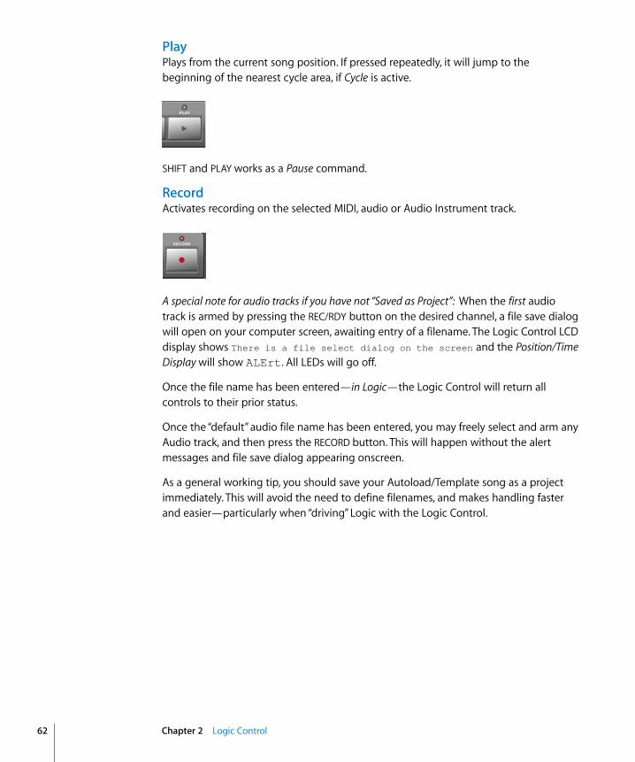
62
PlayPlays from the current song position. If pressed repeatedly, it will jump to the beginning of the nearest cycle area, if Cycle is active.
SHIFT and PLAY works as a Pause command.
RecordActivates recording on the selected MIDI, audio or Audio Instrument track.
A special note for audio tracks if you have not “Saved as Project”: When the first audio track is armed by pressing the REC/RDY button on the desired channel, a file save dialog will open on your computer screen, awaiting entry of a filename. The Logic Control LCD display shows There is a file select dialog on the screen and the Position/Time Display will show ALErt. All LEDs will go off.
Once the file name has been entered—in Logic—the Logic Control will return all controls to their prior status.
Once the “default” audio file name has been entered, you may freely select and arm any Audio track, and then press the RECORD button. This will happen without the alert messages and file save dialog appearing onscreen.
As a general working tip, you should save your Autoload/Template song as a project immediately. This will avoid the need to define filenames, and makes handling faster and easier—particularly when “driving” Logic with the Logic Control.
Chapter 2 Logic Control
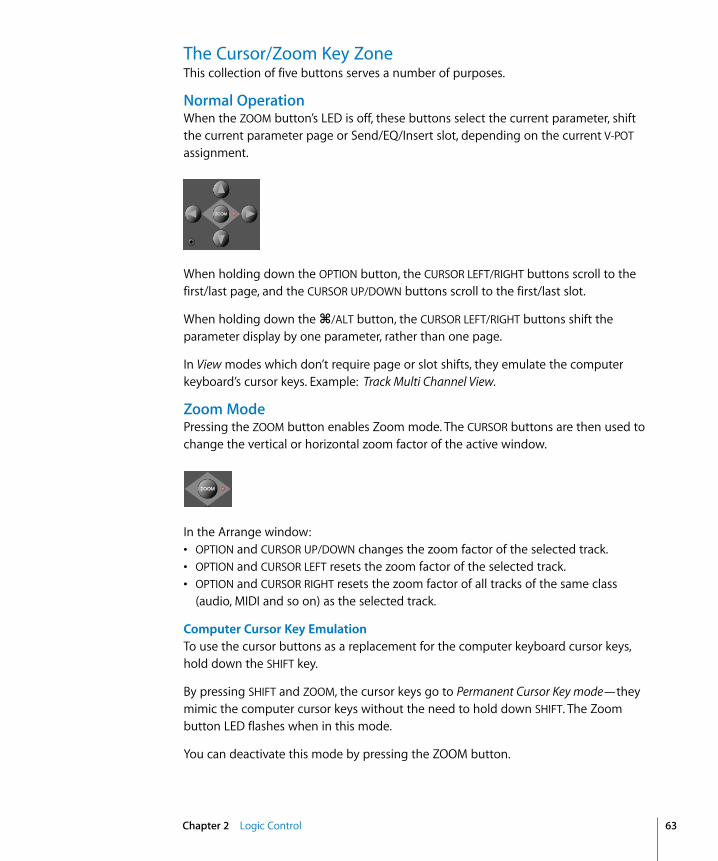
The Cursor/Zoom Key ZoneThis collection of five buttons serves a number of purposes.
Normal OperationWhen the ZOOM button’s LED is off, these buttons select the current parameter, shift the current parameter page or Send/EQ/Insert slot, depending on the current V-POT assignment.
When holding down the OPTION button, the CURSOR LEFT/RIGHT buttons scroll to the first/last page, and the CURSOR UP/DOWN buttons scroll to the first/last slot.
When holding down the C/ALT button, the CURSOR LEFT/RIGHT buttons shift the parameter display by one parameter, rather than one page.
In View modes which don’t require page or slot shifts, they emulate the computer keyboard’s cursor keys. Example: Track Multi Channel View.
Zoom ModePressing the ZOOM button enables Zoom mode. The CURSOR buttons are then used to change the vertical or horizontal zoom factor of the active window.
In the Arrange window:• OPTION and CURSOR UP/DOWN changes the zoom factor of the selected track.• OPTION and CURSOR LEFT resets the zoom factor of the selected track.• OPTION and CURSOR RIGHT resets the zoom factor of all tracks of the same class
(audio, MIDI and so on) as the selected track.
Computer Cursor Key EmulationTo use the cursor buttons as a replacement for the computer keyboard cursor keys, hold down the SHIFT key.
By pressing SHIFT and ZOOM, the cursor keys go to Permanent Cursor Key mode—they mimic the computer cursor keys without the need to hold down SHIFT. The Zoom button LED flashes when in this mode.
You can deactivate this mode by pressing the ZOOM button.
Chapter 2 Logic Control 63

64
The Jog/Scrub Wheel ZoneThe Jog/Scrub Wheel and SCRUB button can be used to navigate through the song, which is useful for a number of Transport tasks. Simply turn the dial to use it. The following Scrub modes change the behavior of the Jog/Scrub Wheel.• SCRUB mode off: the Jog/Scrub Wheel moves the SPL.• SCRUB mode on: the Jog/Scrub Wheel performs “scrubbing,” which allows you to
hear the data of the selected track while scrolling/moving through the song.Audio tracks are normally played back at their original speed. If you would prefer to hear them at double speed, choose Preferences > Audio > Drivers, and set Maximum Scrub Speed to Double in the pull-down menu.
Note: You can also use the SCRUB button for Pause functionality.
• SHUTTLE mode (SCRUB button LED flashing): the Jog/Scrub Wheel shuttles the SPL—turning it increases or decreases the speed of SPL movement.
Assignment OverviewThe following assigment tables are broken down into “zones” of the Logic Control.
Channel Strip (x8)Logic Control Modifier Function/Comments
V-POT — Modify parameter displayed in LCD.
OPTION Set parameter to minimum or maximum value.
C/ALT Modify parameter at high resolution.
V-SELECT — Set parameter displayed on LCD to default value, or: Switch between two possible values.
Flashing pre-selection:
— Enter the pre-selected value.
Menu options:
— Enter whatever option is visible in display.
If track is folder:
— Enter folder.
REC/RDY — Toggle Record Enable button of track.
OPTION Disable Record Enable button for all tracks.
SOLO — Toggle Solo button of track’s Audio Object.
OPTION Disable Solo button for all Audio Objects.
In Send Destination/Level Multi Channel View:
— Toggle pre/post status of selected send.
In Send Destination/Level Channel Strip View:
— Toggle pre/post of send on selected track.
Chapter 2 Logic Control

MUTE — Toggle Mute button of track’s Audio Object.
OPTION Disable Mute button for all Audio Objects.
In Track Multi Channel View:
SHIFT Toggle mute/bypass of the shown parameter.
In EQ Multi Channel View:
SHIFT Toggle bypass of the current EQ band.
In EQ Frequency/Gain View:
— Toggle bypass of selected EQ band.
In Send Multi Channel View:
SHIFT Toggle bypass of selected send.
In Send Destination/Level Multi Channel View:
— Toggle bypass of selected send.
In Send Destination/Level Channel Strip View:
— Toggle mute of send on selected track.
In Plug-in Multi Channel View:
SHIFT Toggle bypass of plug-in.
In Instrument Multi Channel View:
SHIFT Toggle bypass of instrument.
SELECT — Select track.
SHIFT Set track volume to unity level (0 dB).
OPTION Creates a new track with the same instrument as the selected track and switches to Arrange View.
SHIFT+OPTION
Create a new track with the next instrument (following the selected track) and switches to Arrange View.
FADER — Adjust volume.
In Flip mode “Duplicate”:
— Same function as V-POT of same channel.
In Flip mode “Swap”:
— Swap function with V-POT of same channel.
In EQ Frequency/Gain View:
— Adjust gain of selected EQ band.
In Send Destination/Level Multi Channel View:
— Adjust send level of selected send.
In Send Destination/Level Channel Strip View:
— Adjust send level of send on selected track.
Logic Control Modifier Function/Comments
Chapter 2 Logic Control 65

66
ASSIGNMENT SectionHold down to show soft-button menu; release to switch V-POTs to Multi Channel or Channel Strip views for:
DISPLAY Parameters
Logic Control Modifier Function/Comments
TRACK — Track parameters
PAN/SURROUND — Pan parameters
EQ — EQ parameters
SEND — Send parameters
PLUG-IN — Plug-in selection or Plug-in Edit mode
INSTRUMENT — Instrument selection or Instrument Edit mode
BANK <> — Shift fader bank left/right by number of channel strips.
OPTION Shift fader bank to beginning or end.
CHANNEL<> — Shift fader bank left/right by one channel.
OPTION Shift fader bank to beginning or end.
FLIP — Toggle Flip mode between Off” and Duplicate.
SHIFT Toggle Flip mode between Off and Swap.
CONTROL Toggle Flip mode between Off” and Zero (turns fader motors off ).
GLOBAL VIEW — Toggle between Mixer View and Global View.
SHIFT Toggle between Mixer View and Arrange View.
Logic Control Modifier Function/Comments
NAME/VALUE — Toggle between parameter name and parameter value display.
SHIFT Cycle through level meter displays: vertical, horizontal and off.
OPTION Toggle between track name and track number:name display.
CONTROL Clear clip/overload flags.
C/ALT Enter control surface group settings mode.
SMPTE/BEATS — Toggle between SMPTE and beat format in clock display.
Chapter 2 Logic Control
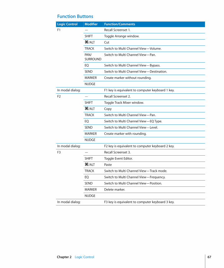
Function ButtonsLogic Control Modifier Function/Comments
F1 — Recall Screenset 1.
SHIFT Toggle Arrange window.
C/ALT Cut
TRACK Switch to Multi Channel View—Volume.
PAN/SURROUND
Switch to Multi Channel View—Pan.
EQ Switch to Multi Channel View—Bypass.
SEND Switch to Multi Channel View—Destination.
MARKER Create marker without rounding.
NUDGE
In modal dialog: F1 key is equivalent to computer keyboard 1 key.
F2 — Recall Screenset 2.
SHIFT Toggle Track Mixer window.
C/ALT Copy
TRACK Switch to Multi Channel View—Pan.
EQ Switch to Multi Channel View—EQ Type.
SEND Switch to Multi Channel View—Level.
MARKER Create marker with rounding.
NUDGE
In modal dialog: F2 key is equivalent to computer keyboard 2 key.
F3 — Recall Screenset 3.
SHIFT Toggle Event Editor.
C/ALT Paste
TRACK Switch to Multi Channel View—Track mode.
EQ Switch to Multi Channel View—Frequency.
SEND Switch to Multi Channel View—Position.
MARKER Delete marker.
NUDGE
In modal dialog: F3 key is equivalent to computer keyboard 3 key.
Chapter 2 Logic Control 67
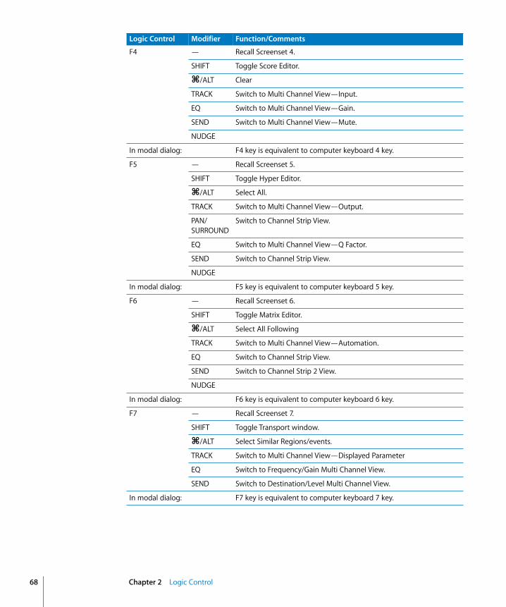
68
F4 — Recall Screenset 4.
SHIFT Toggle Score Editor.
C/ALT Clear
TRACK Switch to Multi Channel View—Input.
EQ Switch to Multi Channel View—Gain.
SEND Switch to Multi Channel View—Mute.
NUDGE
In modal dialog: F4 key is equivalent to computer keyboard 4 key.
F5 — Recall Screenset 5.
SHIFT Toggle Hyper Editor.
C/ALT Select All.
TRACK Switch to Multi Channel View—Output.
PAN/SURROUND
Switch to Channel Strip View.
EQ Switch to Multi Channel View—Q Factor.
SEND Switch to Channel Strip View.
NUDGE
In modal dialog: F5 key is equivalent to computer keyboard 5 key.
F6 — Recall Screenset 6.
SHIFT Toggle Matrix Editor.
C/ALT Select All Following
TRACK Switch to Multi Channel View—Automation.
EQ Switch to Channel Strip View.
SEND Switch to Channel Strip 2 View.
NUDGE
In modal dialog: F6 key is equivalent to computer keyboard 6 key.
F7 — Recall Screenset 7.
SHIFT Toggle Transport window.
C/ALT Select Similar Regions/events.
TRACK Switch to Multi Channel View—Displayed Parameter
EQ Switch to Frequency/Gain Multi Channel View.
SEND Switch to Destination/Level Multi Channel View.
In modal dialog: F7 key is equivalent to computer keyboard 7 key.
Logic Control Modifier Function/Comments
Chapter 2 Logic Control
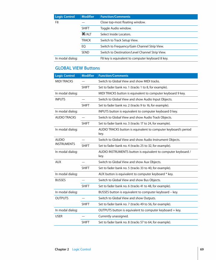
GLOBAL VIEW Buttons
F8 — Close top-most floating window.
SHIFT Toggle Audio window.
C/ALT Select Inside Locators.
TRACK Switch to Track Setup View.
EQ Switch to Frequency/Gain Channel Strip View.
SEND Switch to Destination/Level Channel Strip View.
In modal dialog: F8 key is equivalent to computer keyboard 8 key.
Logic Control Modifier Function/Comments
Logic Control Modifier Function/Comments
MIDI TRACKS — Switch to Global View and show MIDI tracks.
SHIFT Set to fader bank no. 1 (tracks 1 to 8, for example).
In modal dialog: MIDI TRACKS button is equivalent to computer keyboard 9 key.
INPUTS — Switch to Global View and show Audio Input Objects.
SHIFT Set to fader bank no. 2 (tracks 9 to 16, for example).
In modal dialog: INPUTS button is equivalent to computer keyboard 0 key.
AUDIO TRACKS — Switch to Global View and show Audio Track Objects.
SHIFT Set to fader bank no. 3 (tracks 17 to 24, for example).
In modal dialog: AUDIO TRACKS button is equivalent to computer keyboard’s period key.
AUDIO INSTRUMENTS
— Switch to Global View and show Audio Instrument Objects.
SHIFT Set to fader bank no. 4 (tracks 25 to 32, for example).
In modal dialog: AUDIO INSTRUMENTS button is equivalent to computer keyboard / key.
AUX — Switch to Global View and show Aux Objects.
SHIFT Set to fader bank no. 5 (tracks 33 to 40, for example).
In modal dialog: AUX button is equivalent to computer keyboard * key.
BUSSES — Switch to Global View and show Bus Objects.
SHIFT Set to fader bank no. 6 (tracks 41 to 48, for example).
In modal dialog: BUSSES button is equivalent to computer keyboard – key.
OUTPUTS — Switch to Global View and show Outputs.
SHIFT Set to fader bank no. 7 (tracks 49 to 56, for example).
In modal dialog: OUTPUTS button is equivalent to computer keyboard + key.
USER — Currently unassigned.
SHIFT Set to fader bank no. 8 (tracks 57 to 64, for example).
Chapter 2 Logic Control 69
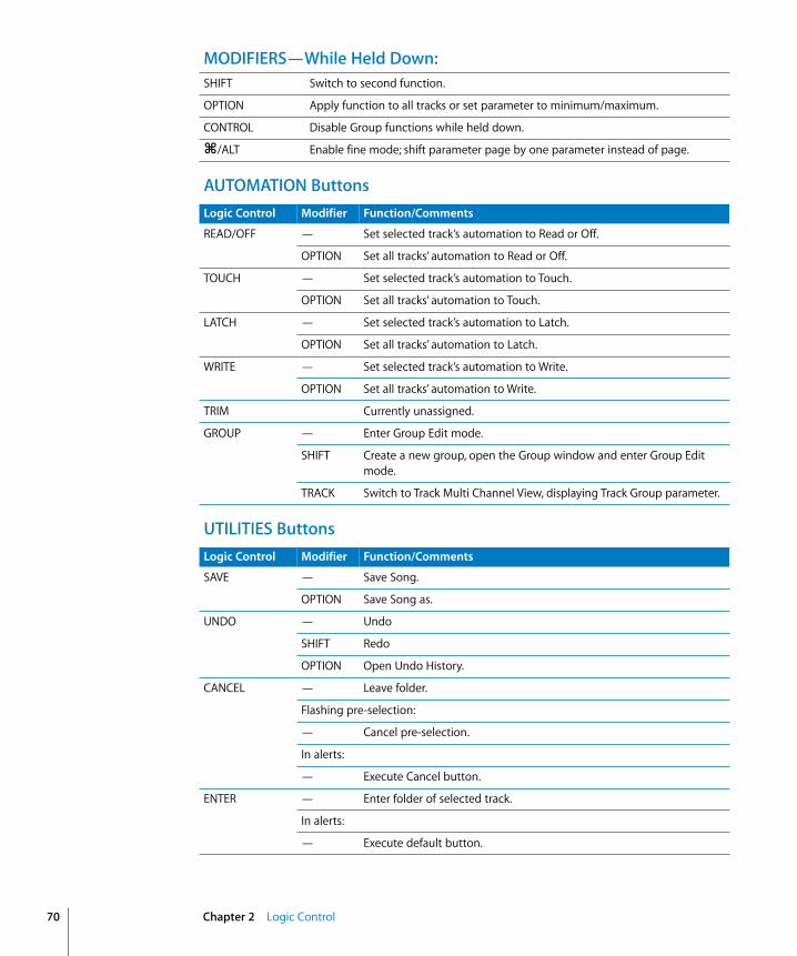
70
MODIFIERS—While Held Down:
AUTOMATION Buttons
UTILITIES Buttons
SHIFT Switch to second function.
OPTION Apply function to all tracks or set parameter to minimum/maximum.
CONTROL Disable Group functions while held down.
C/ALT Enable fine mode; shift parameter page by one parameter instead of page.
Logic Control Modifier Function/Comments
READ/OFF — Set selected track’s automation to Read or Off.
OPTION Set all tracks’ automation to Read or Off.
TOUCH — Set selected track’s automation to Touch.
OPTION Set all tracks’ automation to Touch.
LATCH — Set selected track’s automation to Latch.
OPTION Set all tracks’ automation to Latch.
WRITE — Set selected track’s automation to Write.
OPTION Set all tracks’ automation to Write.
TRIM Currently unassigned.
GROUP — Enter Group Edit mode.
SHIFT Create a new group, open the Group window and enter Group Edit mode.
TRACK Switch to Track Multi Channel View, displaying Track Group parameter.
Logic Control Modifier Function/Comments
SAVE — Save Song.
OPTION Save Song as.
UNDO — Undo
SHIFT Redo
OPTION Open Undo History.
CANCEL — Leave folder.
Flashing pre-selection:
— Cancel pre-selection.
In alerts:
— Execute Cancel button.
ENTER — Enter folder of selected track.
In alerts:
— Execute default button.
Chapter 2 Logic Control
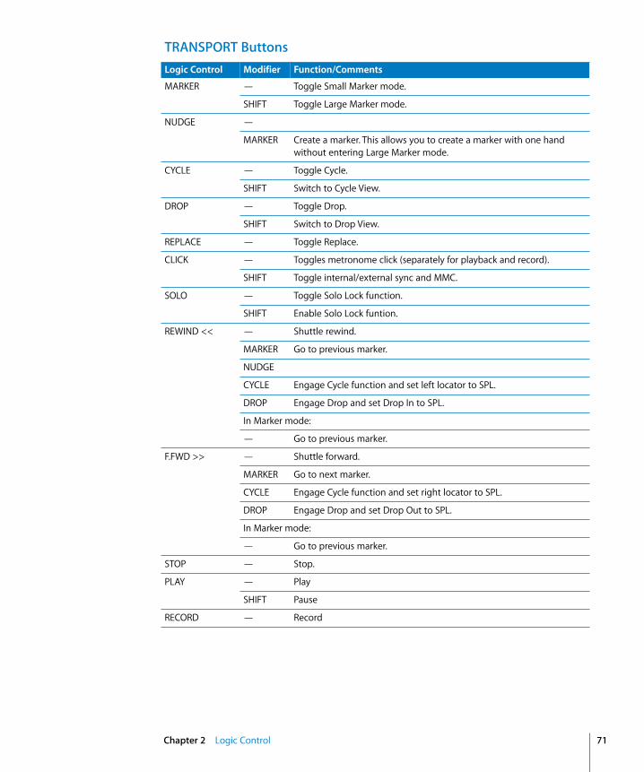
TRANSPORT ButtonsLogic Control Modifier Function/Comments
MARKER — Toggle Small Marker mode.
SHIFT Toggle Large Marker mode.
NUDGE —
MARKER Create a marker. This allows you to create a marker with one hand without entering Large Marker mode.
CYCLE — Toggle Cycle.
SHIFT Switch to Cycle View.
DROP — Toggle Drop.
SHIFT Switch to Drop View.
REPLACE — Toggle Replace.
CLICK — Toggles metronome click (separately for playback and record).
SHIFT Toggle internal/external sync and MMC.
SOLO — Toggle Solo Lock function.
SHIFT Enable Solo Lock funtion.
REWIND << — Shuttle rewind.
MARKER Go to previous marker.
NUDGE
CYCLE Engage Cycle function and set left locator to SPL.
DROP Engage Drop and set Drop In to SPL.
In Marker mode:
— Go to previous marker.
F.FWD >> — Shuttle forward.
MARKER Go to next marker.
CYCLE Engage Cycle function and set right locator to SPL.
DROP Engage Drop and set Drop Out to SPL.
In Marker mode:
— Go to previous marker.
STOP — Stop.
PLAY — Play
SHIFT Pause
RECORD — Record
Chapter 2 Logic Control 71
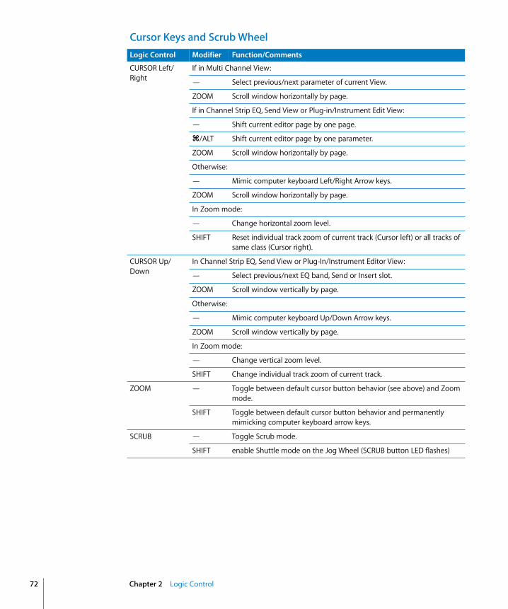
72
Cursor Keys and Scrub WheelLogic Control Modifier Function/Comments
CURSOR Left/Right
If in Multi Channel View:
— Select previous/next parameter of current View.
ZOOM Scroll window horizontally by page.
If in Channel Strip EQ, Send View or Plug-in/Instrument Edit View:
— Shift current editor page by one page.
C/ALT Shift current editor page by one parameter.
ZOOM Scroll window horizontally by page.
Otherwise:
— Mimic computer keyboard Left/Right Arrow keys.
ZOOM Scroll window horizontally by page.
In Zoom mode:
— Change horizontal zoom level.
SHIFT Reset individual track zoom of current track (Cursor left) or all tracks of same class (Cursor right).
CURSOR Up/Down
In Channel Strip EQ, Send View or Plug-In/Instrument Editor View:
— Select previous/next EQ band, Send or Insert slot.
ZOOM Scroll window vertically by page.
Otherwise:
— Mimic computer keyboard Up/Down Arrow keys.
ZOOM Scroll window vertically by page.
In Zoom mode:
— Change vertical zoom level.
SHIFT Change individual track zoom of current track.
ZOOM — Toggle between default cursor button behavior (see above) and Zoom mode.
SHIFT Toggle between default cursor button behavior and permanently mimicking computer keyboard arrow keys.
SCRUB — Toggle Scrub mode.
SHIFT enable Shuttle mode on the Jog Wheel (SCRUB button LED flashes)
Chapter 2 Logic Control

External Inputs
Jog Wheel — Move song position line.
CYCLE Set the Left locator to the current SPL, advance the SPL as normally, then set the Right locator to the SPL. Further Jog Wheel turns while still holding down CYCLE advances the SPL and sets the Right locator again. Tip: Rotating the Jog Wheel counterclockwise while holding down CYCLE defines a skip-cycle range.
DROP Set the Drop In locator to the current SPL, advance the SPL as normally, then set the Drop Out locator to the SPL. Further Jog Wheel turns while still holding down DROP advances the SPL and sets the Drop out locator again.
In Scrub mode (SCRUB button LED on):
— Scrub
In Shuttle mode (SCRUB button LED flashing):
— Shuttle
Logic Control Modifier Function/Comments
Logic Control Modifier Function
USER SWITCH A — Play/Stop
USER SWITCH B — Drop In/Out
EXTERNAL CONTROL
— Master Volume
Chapter 2 Logic Control 73


3
3 Frontier Design TranzPortSet UpPlease follow these steps before using your control surface with Logic Express 7.• Ensure that the software shipped with the TranzPort is installed.• Make sure that the “Tranz Bridge” (the wireless transmitter) is connected to the
computer via USB.• When Logic Express 7 is launched, it installs the TranzPort automatically, and sets it to
“native mode.”
LCDThe LCD displays the following information:• Top line left: name of currently displayed track.• Top line middle: volume of currently displayed track.• Top line right: panning of currently displayed track.• Bottom line left: level meter of currently displayed track (stereo).• Bottom line right: current clock position.
Assignment OverviewA right-aligned SHIFT (or other) button below a button description indicates that the button has an alternate meaning/use while holding down this modifier.
Channel StripControl Assignment
<CHAN Shift the currently displayed track to the left by one track.
SHIFT Shift the currently displayed track left by eight tracks.
CHAN> Shift the currently displayed track right by one track.
SHIFT Shift the currently displayed track right by eight tracks.
REC Toggle Record Enable button for the currently displayed track.
SHIFT Disable Record Enable button for all tracks.
SOLO Toggle Solo for the currently displayed track.
SHIFT Disable Solo for all tracks.
75

76
Master Section
MUTE Toggle Mute for the currently displayed track.
SHIFT Disable Mute for all tracks.
ANY SOLO Lit if any tracks or Regions are soloed.
UNDO Undo
SHIFT Redo
Control Assignment
Control Assignment
SHIFT Modifier for function of other controls.
IN Go to left Cycle locator.
PUNCH Engage Drop and set Drop In locator to SPL.
LOOP Engage Cycle and sets left Cycle locator to SPL.
OUT Go to right Cycle locator.
PUNCH Engage Drop and set Drop Out locator to SPL.
LOOP Engage Cycle and set right Cycle locator to SPL.
PUNCH Toggle Drop mode.
LOOP Toggle Cycle mode.
PREV Go to previous marker.
SHIFT Set locators by previous marker.
ADD Create marker at SPL.
SHIFT Delete marker at SPL.
NEXT Go to next marker.
SHIFT Set locators by next marker.
Jog Wheel Depending on current Jog Wheel mode:• Move SPL by bars.• Audio scrubbing or• Shuttle.
SHIFT Adjust volume of the currently displayed track.
LOOP Set the Left locator to the current SPL, advance the SPL as per usual, then set the Right locator to the SPL. Further Jog Wheel use while holding down LOOP advances the SPL and sets the Right locator. Tip: Rotating the Jog Wheel counter-clockwise while holding down LOOP defines a skip-cycle range.
DROP Set the Drop In locator to the current SPL, advance the SPL as per usual, then set the Drop Out locator to the SPL. Further jog wheel use while holding down DROP advances the SPL and sets the Drop Out locator.
REW Shuttle backward.
SHIFT Go to last play position.
Chapter 3 Frontier Design TranzPort

External Input
PUNCH Engage Drop mode and set Drop In locator to SPL.
LOOP Engage Cycle mode and set left locator to SPL.
F FWD Shuttle forward.
PUNCH Engage Drop mode and set Drop Out locator to SPL.
LOOP Engage Cycle moce and set right locator to SPL.
STOP Stop
SHIFT Switch Jog Wheel modes between Move SPL by Bars, Audio Scrubbing and Shuttle.
PLAY Play
SHIFT Pause
RECORD Record
SHIFT Save
Control Assignment
Control Assignment
Foot Switch Drop In/Out
Chapter 3 Frontier Design TranzPort 77


4
4 J.L.Cooper CS-32 MiniDeskSet UpPlease follow these steps before using your control surface with Logic Express 7.• Install the software that ships with the CS-32.• Ensure that the CS-32 is in Host mode:• Make sure that your CS-32 unit(s) are connected to the computer via USB or MIDI.
USB units are installed automatically. You must manually scan for MIDI units:
• Choose Logic > Preferences > Control Surfaces > Setup.• Choose New > Install in the Setup window’s local menu.• Select the CS-32 from the list in the Install window.• Click the Scan button.
Assignment OverviewA right-aligned modifier button (such as SHIFT) below a button description indicates that the button has an alternate meaning/use while holding down this modifier.
DisplayThe 2-digit 7-segment display shows information on the current mode and currently edited parameter:
Display text Meaning
-- A toggle parameter (Solo, Mute, Rec/Rdy) has been disabled.
AE Mute buttons 1–6 display/set Automation Enable.
AS Pots are in Pan/Send Assignment mode.
b1–b9 Pots are in Plug-in or Instrument bank select mode.
In Pots are in Instrument Edit mode.
Lt Mute buttons display/set “Latch” automation mode.
MI Mute buttons display/set “MIDI” automation mode.
Mu Mute has been enabled.
P1–P9 Pots are in Plug-in Edit mode.
PA Pots are in Pan/Send mode.
79
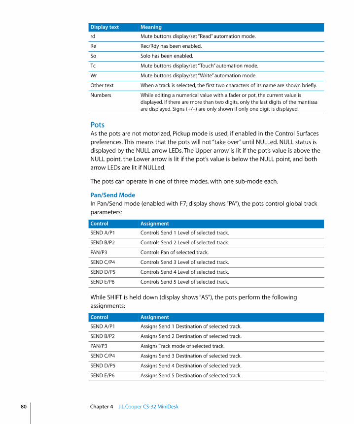
80
PotsAs the pots are not motorized, Pickup mode is used, if enabled in the Control Surfaces preferences. This means that the pots will not “take over” until NULLed. NULL status is displayed by the NULL arrow LEDs. The Upper arrow is lit if the pot’s value is above the NULL point, the Lower arrow is lit if the pot’s value is below the NULL point, and both arrow LEDs are lit if NULLed.
The pots can operate in one of three modes, with one sub-mode each.
Pan/Send ModeIn Pan/Send mode (enabled with F7; display shows “PA”), the pots control global track parameters:
While SHIFT is held down (display shows “AS”), the pots perform the following assignments:
rd Mute buttons display/set “Read” automation mode.
Re Rec/Rdy has been enabled.
So Solo has been enabled.
Tc Mute buttons display/set “Touch” automation mode.
Wr Mute buttons display/set “Write” automation mode.
Other text When a track is selected, the first two characters of its name are shown briefly.
Numbers While editing a numerical value with a fader or pot, the current value is displayed. If there are more than two digits, only the last digits of the mantissa are displayed. Signs (+/–) are only shown if only one digit is displayed.
Display text Meaning
Control Assignment
SEND A/P1 Controls Send 1 Level of selected track.
SEND B/P2 Controls Send 2 Level of selected track.
PAN/P3 Controls Pan of selected track.
SEND C/P4 Controls Send 3 Level of selected track.
SEND D/P5 Controls Send 4 Level of selected track.
SEND E/P6 Controls Send 5 Level of selected track.
Control Assignment
SEND A/P1 Assigns Send 1 Destination of selected track.
SEND B/P2 Assigns Send 2 Destination of selected track.
PAN/P3 Assigns Track mode of selected track.
SEND C/P4 Assigns Send 3 Destination of selected track.
SEND D/P5 Assigns Send 4 Destination of selected track.
SEND E/P6 Assigns Send 5 Destination of selected track.
Chapter 4 J.L.Cooper CS-32 MiniDesk

Instrument Edit ModeIn Instrument Edit mode (enabled with F8; display shows “In”), the pots control instrument parameters.
With SHIFT held down (display shows “b1”–“b9”), you can choose the parameter bank (see “Cursor Section” on page 83).
Plug-in Edit ModeIn Plug-in Edit mode (enabled with F9, display shows “P1”–”P9”), the pots control plug-in parameters of the currently selected insert.
With SHIFT held down (display shows “b1”–”b9”), you can choose the current insert and parameter bank (see “Cursor Section” on page 83).
Channel StripsControl Assignment
PAN SELECT/TRACK SELECT
Selects track.
SOLO Toggles Solo.
LOCATE Navigates to markers 1–32.
SHIFT LOCATE 17: Creates new marker.LOCATE 18: Creates new marker without rounding.LOCATE 19: Deletes marker at SPL.LOCATE 25: Opens Marker List.LOCATE 26: Opens Marker Text window.LOCATE 28: Sets locators by previous marker.LOCATE 29: Sets locators by current marker.LOCATE 30: Sets locators by next marker.LOCATE 31: Navigates to previous marker.LOCATE 32: Navigates to next marker.
MUTE Toggles Mute.
F1 Automation Enable setup (display shows “AE”).MUTE 1: Toggles automation of volume.MUTE 2: Toggles automation of pan.MUTE 3: Toggles automation of mute.MUTE 4: Toggles automation of solo.MUTE 5: Toggles automation of send.MUTE 6: Toggles automation of plug-in parameters.
F2 Displays/sets automation mode to “Read” (display shows “Td”).
F3 Displays/sets automation mode to “Touch” (display shows “Tc”).
F4 Displays/sets automation mode to “Latch” (display shows “Lt”).
F5 Displays/sets automation mode to “Write” (display shows “Wr”).
F6 Displays/sets automation mode to “MIDI” (display shows “MI”).
Chapter 4 J.L.Cooper CS-32 MiniDesk 81

82
Bank Button
F Key Section
ARM Toggles Record Enable button.
Faders Control volume. As the faders don’t offer feedback, Pickup mode is used, if enabled in the Control Surfaces preferences. This means that they will not “take over” until NULLed. NULL status is displayed by the NULL arrow LEDs. Upper arrow is lit if the pot’s value is above the NULL point, the lower arrow is lit if the pot’s value is below the NULL point, and both are lit if NULLed.
Control Assignment
Control Assignment
(Small red button with green LED)
LED off: black labels of channel strip buttons apply (TRK/LOC/ARM).LED on: white labels of channel strip buttons apply (PAN/SOLO/MUTE).
Control Assignment
SHIFT Modifier for function of other controls. See right-aligned “SHIFT” in left column.
F1 While held down, MUTE buttons 1–6 toggle automation of certain parameters (see MUTE).
SHIFT Toggles Cycle mode.
F2 While held down, MUTE buttons set automation mode to Read.
SHIFT Toggles Drop mode.
F3 While held down, MUTE buttons set automation mode to Touch.
SHIFT Sets left locator by current SPL.
F4 While held down, MUTE buttons set automation mode to Latch.
SHIFT Sets right locator by current SPL.
F5 While held down, MUTE buttons set automation mode to Write.
SHIFT Sets Drop In locator by current SPL.
F6 While held down, MUTE buttons set automation mode to MIDI.
SHIFT Sets Drop Out locator by current SPL.
F7 Sets pots to Pan/Send mode (display shows “PA”).
SHIFT Toggles metronome click.
F8 Sets pots to Instrument Edit mode (display shows “In”).
F9 Sets pots to Plug-in Edit mode (display shows “P1”–”P9”).
Chapter 4 J.L.Cooper CS-32 MiniDesk

Cursor Section
Transport Section
Jog Wheel Section
Control Assignment
Up Zooms out vertically.
SHIFT In Plug-in edit mode: decrements current Insert slot.
Down Zooms in vertically.
SHIFT In Plug-in Edit mode: increments current Insert slot.
Left Zooms out horizontally.
SHIFT In Instrument and Plug-in Edit modes: decrements current parameter bank.
Right Zooms in horizontally.
SHIFT In Instrument and Plug-in Edit modes: increments current parameter bank.
Control Assignment
RECORD Record
STOP Stop
REW Moves SPL backward by one bar.
PLAY Play
F FWD Moves SPL forward by one bar.
Control Assignment
Jog Wheel SCRUB off: moves SPL in bars.SCRUB on: Audio Scrubbing.SHUTTLE on: Shuttle mode.
SCRUB Toggles Jog Wheel between Move SPL by Bars and Audio Scrubbing mode.
SHUTTLE Toggles Jog Wheel between Move SPL by Bars and Shuttle mode.
Chapter 4 J.L.Cooper CS-32 MiniDesk 83

5
5 J.L.Cooper FaderMaster 4/100RequirementsYou need one or more FaderMaster 4/100 (MIDI or USB version) units with firmware version 1.03 or higher.
Important: If you have older firmware (see the sticker on the back of the unit), please contact J.L.Cooper.
Set UpPlease follow these steps before using your control surface with Logic Express 7.• USB model only: install the software that ships with the FaderMaster 4/100.• Ensure that your FaderMaster 4/100 unit(s) are connected to the computer via USB or
MIDI.
USB units are installed automatically.
You must manually scan for MIDI units: 1 Choose Logic > Preferences > Control Surfaces > Setup.
2 Choose New > Install in the Setup window’s local menu.
3 Select the FaderMaster 4/100 from the list in the Install window.
4 Click the Scan button.
Note: You can combine several FaderMaster 4/100 units to form one large virtual control surface. The meaning/functionality of the Track buttons, however, are individually switched for each unit.
85
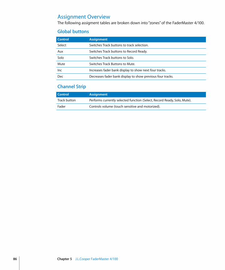
86
Assignment OverviewThe following assigment tables are broken down into “zones” of the FaderMaster 4/100.
Global buttons
Channel Strip
Control Assignment
Select Switches Track buttons to track selection.
Aux Switches Track buttons to Record Ready.
Solo Switches Track buttons to Solo.
Mute Switches Track Buttons to Mute.
Inc Increases fader bank display to show next four tracks.
Dec Decreases fader bank display to show previous four tracks.
Control Assignment
Track button Performs currently selected function (Select, Record Ready, Solo, Mute).
Fader Controls volume (touch sensitive and motorized).
Chapter 5 J.L.Cooper FaderMaster 4/100
6
6 Korg microKONTROL and KONTROL49Set UpPlease follow these steps before using your control surface with Logic Express 7.1.• Ensure that your unit(s) is/are connected to the computer via USB.• Boot Logic, and the unit(s) will be scanned for, and installed automatically.• When Logic launches, the microKONTROL/KONTROL49 is automatically set to “Native
mode”—internal Scene settings are ignored.
Note: If installation and identification fails, it may be possible that the microKONTROL/KONTROL49 reaction time is too slow, due to USB bus-power issues. In this situation, connect the supplied power adapter, and set the power switch to the “DC” position.
When Logic quits (or the icon is removed from the Control Surface Setup window), the microKONTROL/KONTROL49 is reset to normal operation.
Assignment OverviewA right-aligned modifier button (shown below a button description) indicates that the button has an alternate meaning/use while holding down this modifier.
PadsThe Pads can operate in one of eight modes and three overlays. While pressing SCENE, the Pads allow you to select modes for the Pads and channel strips. Releasing SCENE without pressing a Pad does not affect the currently selected Pad or Channel Strip modes.
Pad Assignment
1 Switches Pads to Transport mode.
2 Switches Pads to Solo/Mute mode.
3 Switches Pads to Rec/Select mode.
4–8 Switches Pads to User 4–8 mode.These modes have unassigned Pads. You can add assignments to key commands with Logic’s Learn function.
9 Switches channel strips to Pan mode.
10 Switches channel strips to Send mode.
87

88
Transport ModeThis mode is enabled by pressing SCENE and Pad 1.
Solo/Mute ModeThis mode is enabled by pressing SCENE and Pad 2.
Rec/Select ModeThis mode is enabled by pressing SCENE and Pad 3.
11 Switches channel strips to Automation mode.
12 Switches channel strips to Instrument Edit mode.
13 Switches channel strips to Plug-in Edit mode.
14–16 Switches channel strips to User 6–8 mode.These modes have unassigned encoders. You can add assignments with the Logic Learn function.
Pad Assignment
Pad Assignment
1 Sets main encoder to Transport mode.
2 Sets main encoder to Scrub mode.
3 Sets main encoder to Shuttle mode.
7 Toggles sync between internal and external.
8 Toggles metronome click (separately for Playback and Record).
9 Toggles Cycle function.
10 Toggles Drop function.
11 Toggles Replace function.
12 Toggles Solo function.
13 Record
14 Pause
15 Play
16 Stop
Pad Assignment
1–8 Toggles Solo for the eight tracks being controlled with the eight channel strips.
9–16 Toggles Mute for the eight tracks being controlled with the eight channel strips.
Pad Assignment
1–8 Toggles Record Enable button for the eight tracks being controlled with the eight channel strips.
9–16 Selects one of the eight tracks being controlled with the eight channel strips.
Chapter 6 Korg microKONTROL and KONTROL49

User 4–8 ModesThese modes are enabled by pressing SCENE and Pad 4 to 8.
In these modes, the Pads are unassigned. Use Logic’s Learn function (Logic > Preferences > Control Surfaces > Learn Assignment for xxx) to assign them to key commands, for example.
Send ModeThis mode is enabled by pressing SCENE and Pad 10.
Send overlayPressing SETTING while the encoders are in Send mode, changes the operation of the Pads in Send mode.
Plug-in Edit ModeThis mode is enabled by pressing SCENE and Pad 13.
Plug-in Edit overlayPressing SETTING while the encoders are in Plug-in Edit mode changes the operation of the Pads in Plug-in Edit mode.
Main SectionThe main LCD shows information on the current mode of the encoders.
Pad Assignment
1–8 Toggles send bypass of the currently selected send for the eight channel strips.
9–16 Toggles send position (Pre/Post) of the currently selected send for the eight channel strips.
Pad Assignment
1–8 Toggles plug-in bypass of the currently selected Insert slot for the eight channel strips.
Display text Meaning
<Instrument name> Encoders edit Instrument parameters.
<Plug-in name> Encoders edit Plug-in parameters (xx is for the currently selected insert).
Automatn Encoders control Automation mode.
Ins. x (SETTING held down) Main encoder chooses Plug-in insert.
ModePad? Displayed while SCENE button is held down.
Pan Encoders control pan.
Send x Encoders control send level of send x.
User 6 Channel Strip User Mode 6. Encoders are initially unassigned.
User 7 Channel Strip User Mode 7. Encoders are initially unassigned.
User 8 Channel Strip User Mode 8. Encoders are initially unassigned.
Chapter 6 Korg microKONTROL and KONTROL49 89

90
The LCD backlight is red while recording, and green at other times.
The controls in the main section have the following meaning:
Channel StripsThere are several modes for the encoders, enabled with SCENE and Pad 9–16.
Control Assignment
Main encoder Controls SPL in one of three modes (see Pads 1–3 in “Transport Mode” on page 88).
SETTING Held down in Send mode:• Main encoder chooses current send.• Pads have special meaning—see “Send Mode” on page 89.• LCDs display send destinations.• Encoders choose send destinations.Holding down in Plug-in Edit mode:• Main encoder chooses current plug-in insert.• Pads have special meaning—see “Plug-in Edit overlay” on page 89.• LCDs display plug-in name of the eight tracks.
MESSAGE Toggles Flip mode. When enabled, the encoders control volume and the faders control the parameter displayed in the LCDs.
SCENE While held down, pads switch Pad and Channel Strip modes. See “Pads” on page 87.
EXIT —
HEX LOCK Shifts fader bank to the previous eight tracks (LED is on if previous tracks exist).
ENTER Shifts fader bank to the next eight tracks (LED is on if subsequent tracks exist).
< Octave Shift Down
> Octave Shift Up
Control Assignment
LCD Shows the parameter controlled by the encoder. The currently chosen value is displayed for a few seconds while operating an encoder or fader.When the encoders are in a multi-channel view (Pan, Send, Send Setup), the background color indicates the track’s automation mode:• green—off or Read• yellow—Touch or Latch• red—Write or MIDI
Encoder Controls the parameter shown directly above the encoder in the LCD.
Fader Controls volume. As the faders don’t offer feedback, “Pickup mode” is used if enabled in the Logic Preferences. This means that they will not “take over” until NULLed.
Chapter 6 Korg microKONTROL and KONTROL49

External InputControl Assignment
Foot Switch Starts and stops playback.
Pedal Controls master volume.
Chapter 6 Korg microKONTROL and KONTROL49 91

7
7 Mackie C4Set UpThe C4 is added to your existing Logic/Mackie Control system in Logic Express 7’s Control Surfaces Setup window. It will automatically be detected when Logic Express 7 is launched.
Note: Although the C4 can be used independently, it is most useful when combined with other control surfaces, particularly the Logic/Mackie Control.
V-POTs, V-SELECTsFunctionality depends on current view mode, and optional overlay (see below).• The top row (row 1) consists of V-POT/V-SELECT 1 to 8.• Row 2 consists of V-POT/V-SELECT 9 to 16.• Row 3 consists of V-POT/V-SELECT 17 to 24.• The bottom row (row 4) consists of V-POT/V-SELECT 25 to 32.
V-POT/V-SELECT 1 to 8While no overlay is active, V-POT/V-SELECTS 1 to 8 (the top row) normally perform in the same way as their counterparts on a Logic Control or Logic Control XT. See “The Assignment Zone” on page 36.
V-POT/V-SELECT 9 to 32These V-POTs have additional functionality in many views.
In Multi Channel Views, the V-POT/V-SELECTs of rows 2, 3 and 4 usually edit the parameter that “follows” the parameter edited on row 1.
In Channel Strip View, all four rows build a group of 32 editable parameters.
In Plug-in and Instrument Edit Views, it can be split into two groups (8/24, 16/16 or 24/8 parameters), see below.
Pan Multi Channel ViewIn Pan/Surround Multi Channel View:• Row 1 edits Pan.
93

94
Note: For further information also see “Multi Channel View” on page 39.
Track Multi Channel ViewIn Track Multi Channel View:• Row 1 edits track parameter 4.• Row 2 edits track parameter 3.• Row 3 edits track parameter 2.• Row 4 edits track parameter 1 (the parameter edited by V-POTs on a Logic Control or
XT in this order: Volume, Pan/Angle, Track Mode, Output, Automation Mode, Displayed Automation Parameter).
The row order is reversed, so that the lowest row (editing parameter 1) is closest to the buttons.
BANK left/right and SINGLE left/right change the parameter edited in row 4, thus affecting the parameters shown/edited in rows 1 to 3.
Note: More information about the Track Multi Channel View can be found in the Track Multi Channel View section, from page 37 onwards.
EQ Multi Channel ViewIn EQ Multi Channel View: • Row 1 edits EQ band bypass.• Row 2 edits EQ band frequency.• Row 3 edits EQ band gain.• Row 4 edits EQ band Q factor.• Slot up/down button selects the edited EQ band.
Note: More information about the EQ Multi Channel View can be found in the Multi Channel View section, from page 40 onwards.
EQ Channel Strip ViewIn EQ Channel Strip View:• Row 1 edits EQ frequency of all eight bands.• Row 2 edits EQ gain of all eight bands.• Row 3 edits EQ band Q factor of all eight bands.• Row 4 edits EQ bypass of all eight bands.
Note: More information about the EQ Channel Strip View can be found in the Multi Channel View section, from page 40 onwards.
Send Multi Channel ViewIn Send Multi Channel View:• Row 1 edits send destination.• Row 2 edits send level.• Row 3 edits send position.
Chapter 7 Mackie C4

• Row 4 edits send mute.
Slot up/down button selects the edited Send slot.
More information about the Send Multi Channel View can be found in the Multi Channel View section, from page 41 onwards.
Send Channel Strip ViewIn Send Channel Strip View:• Rows 1 to 4 edit the 32 Send parameters.
SINGLE left/right shifts the display of the Send parameters.
Note: For more information also see “Channel Strip View” on page 42.
Send Channel Strip View 2In Send Channel Strip View 2:• Rows 1 to 4 edit the 32 Send parameters.
SINGLE left/right shifts the display of the Send parameters.
Note: For more information about Send Channel Strip View 2 see “Alternate Edit Mode Options” on page 42.
Send Destination/Level ViewIn Send Destination/Level View:• Row 1 edits send destination.• Row 2 edits send level.• Row 3 edits send position.• Row 4 edits send mute.
Slot up/down button selects the edited Send slot.
Note: For more information about Send Destination/Level View see “Alternate Edit Mode Options” on page 42.
Plug-in Select Multi Channel ViewSlot up/down button selects the edited plug-in insert.
Note: For more information see “Multi Channel View” on page 44.
Plug-in Edit ViewIn Plug-in Edit View:• V-POT/V-SELECT 1 to 32 builds a group of 32 parameters. Split is possible.• Slot up/down button selects the edited plug-in inserts• BANK left/right shifts the edited parameters by 32. In Split mode, this applies to Split
Upper. When holding down SHIFT, this applies to Split Lower.
Chapter 7 Mackie C4 95

96
• SINGLE left/right shifts the edited parameters by 1. In Split mode, this applies to Split Upper. When holding down SHIFT, this applies to Split Lower.
Note: For more information see “Plug-in Edit View” on page 45.
Instrument Edit ViewIn Instrument Edito View:• V-POT/V-SELECT 1 to 32 build a group of 32 parameters. Split is possible.• BANK left/right shifts the edited parameters by 32. In Split mode, this applies to Split
Upper. When holding down SHIFT, this applies to Split Lower.• SINGLE left/right shifts the edited parameters by 1. In Split mode, this applies to Split
Upper. when holding down SHIFT, this applies to Split Lower.
Note: For more information see “Instrument Edit View” on page 47.
Buttons at BottomThe following section outlines the functionality of the buttons found at the bottom of the C4 control surface unit.
SPLITToggles edit split between 4/0, 1/3, 2/2 and 3/1 rows. Split Edit allows you to simultaneously edit two separate sections of a plug-in/instrument, or even two different plug-ins.
Split Edit is also possible across multiple C4 units. As an example with two units, pressing the SPLIT button offers the following split modes:• 1/7 (Split Upper is top line of first unit, Split Lower is bottom 3 lines of first unit and
all lines of second unit. LED 1/3 is lit.)• 2/6 (Split Upper is top two lines of first unit, Split Lower is bottom two lines of first
unit and all lines of second unit. LED 2/1 is on.)• 3/5 (LED 3/1 is on.)• 4/4 (all 3 LEDs are on.)• 5/3 (all 3 LEDs are on.)• 6/2 (all 3 LEDs are on.)• 7/1 (all 3 LEDs are on.)
LOCKToggles Track Lock. When enabled, selecting a track does not switch the currently selected track.
SPOT ERASECurrently unassigned.
MARKERToggles between Marker overlay (see “Marker Overlay” on page 98) and normal view.
Chapter 7 Mackie C4
TRACKToggles between Track overlay (see “Track Overlay” on page 98) and normal view.
Alternate Mode OptionsHolding down the TRACK button accesses a further sub-menu in the bottom LCD, enabling you to enter Global View with a certain Object type:• V-SELECT 25 switches to MIDI tracks.• V-SELECT 27 switches to Audio tracks.• V-SELECT 28 switches to Audio Instrument tracks.• V-SELECT 29 switches to Auxiliary Objects.• V-SELECT 30 switches to Bus Objects.• V-SELECT 31 switches to Outputs 1 and 2.
Releasing the TRACK button without pressing a V-SELECT returns to Mixer View.
CHAN STRIPToggles between Channel Strip overlay (see “Channel Strip Overlay” on page 98) and normal view.
Alternate Mode OptionsHolding down the CHAN STRIP button accesses a further sub-menu in the bottom LCD:• V-SELECT 25 switches to Pan Channel Strip.• V-SELECT 26 switches to EQ Channel Strip.• V-SELECT 27 switches to Send Channel Strip.
FUNCTIONToggles between Function overlay (see “Function Overlay” on page 99) and normal view.
Modifier ButtonsThe four buttons in this area are similar to those found on your computer keyboard (but are independent from the keyboard modifiers). Many of Logic’s functions behave differently when one or more “modifier” key(s) is pressed, in conjunction with another key or mouse click. This also applies to the C4 control surface. All “modified” C4 commands are covered in each function’s description.
Here is a generic description of the button’s function:• SHIFT: As with Logic Control, switches other buttons to alternate function.• OPTION: As with Logic Control, while held down, parameters are set to minimum/
maximum when edited with V-POT.• x/ALT: As with Logic Control, while held down, parameters are edited in fine mode
with V-POT.
BANK Left/RightShifts parameter display by one page in certain views (see above).
Chapter 7 Mackie C4 97
98
SINGLE Left/RightShifts parameter display by one parameter in certain views (see above).
TRACK L/RShifts the currently edited track (in a Channel Strip View) to the previous or next track. While SHIFT is held down: as above, but for Split Lower.
SLOT UP/DOWNSelects the currently edited EQ, Send or plug-in insert (see above).
Marker OverlayThe Marker overlay is active when the MARKER button light is on. A Logic Control in the control surface group shows “MA” in the assignment display.• V-SELECT 1 to 30 is assigned to markers 1 to 30. The upper LCD line shows the marker
name; the lower line shows “INSIDE” when the SPL is inside a marker.• V-SELECT 31 creates a new marker.• V-SELECT 32 deletes the current marker.
Track OverlayThe Track overlay is active when the TRACK button light is on. A Logic Control in the control surface group shows “tr” in the assignment display.• V-SELECT 1 to 32 changes the currently edited track. When a track is selected for Split
Upper, the lower LCD line displays the word “UPPER”. For a track selected for Split Lower, the word “LOWER” is shown.To select a track for Split Upper, press the appropriate V-SELECT.
To select a track for Split Lower, press the V-SELECT while holding down SHIFT. A Logic Control in the same control surface group shows “tL” in the assignment display.
• BANK left/right shifts the fader bank by 32 tracks.• SINGLE left/right shifts the fader bank by 1 track.
Channel Strip OverlayThe Channel Strip overlay is active when the CHAN STRIP button light is on. A Logic Control in the control surface group shows “CS.” in the assignment display.• V-POT/V-SELECT row 1 edits the frequency and gain of EQ bands 3 to 6 (the parametric
bands).• V-POT/V-SELECT row 2 switches to edit mode for plug-in inserts 1 to 8.• V-POT/V-SELECT row 3 edits Send 1 to 8 Level.• V-POT/V-SELECT 25 switches to Instrument Edit mode.• V-POT/V-SELECT 26 edits track output.• V-POT/V-SELECT 27 edits automation mode.
Chapter 7 Mackie C4
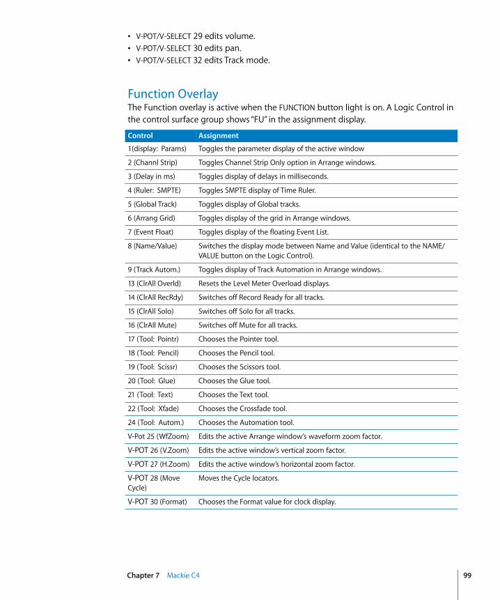
• V-POT/V-SELECT 29 edits volume.• V-POT/V-SELECT 30 edits pan.• V-POT/V-SELECT 32 edits Track mode.
Function OverlayThe Function overlay is active when the FUNCTION button light is on. A Logic Control in the control surface group shows “FU” in the assignment display.
Control Assignment
1(display: Params) Toggles the parameter display of the active window
2 (Channl Strip) Toggles Channel Strip Only option in Arrange windows.
3 (Delay in ms) Toggles display of delays in milliseconds.
4 (Ruler: SMPTE) Toggles SMPTE display of Time Ruler.
5 (Global Track) Toggles display of Global tracks.
6 (Arrang Grid) Toggles display of the grid in Arrange windows.
7 (Event Float) Toggles display of the floating Event List.
8 (Name/Value) Switches the display mode between Name and Value (identical to the NAME/VALUE button on the Logic Control).
9 (Track Autom.) Toggles display of Track Automation in Arrange windows.
13 (ClrAll Overld) Resets the Level Meter Overload displays.
14 (ClrAll RecRdy) Switches off Record Ready for all tracks.
15 (ClrAll Solo) Switches off Solo for all tracks.
16 (ClrAll Mute) Switches off Mute for all tracks.
17 (Tool: Pointr) Chooses the Pointer tool.
18 (Tool: Pencil) Chooses the Pencil tool.
19 (Tool: Scissr) Chooses the Scissors tool.
20 (Tool: Glue) Chooses the Glue tool.
21 (Tool: Text) Chooses the Text tool.
22 (Tool: Xfade) Chooses the Crossfade tool.
24 (Tool: Autom.) Chooses the Automation tool.
V-Pot 25 (WfZoom) Edits the active Arrange window’s waveform zoom factor.
V-POT 26 (V.Zoom) Edits the active window’s vertical zoom factor.
V-POT 27 (H.Zoom) Edits the active window’s horizontal zoom factor.
V-POT 28 (Move Cycle)
Moves the Cycle locators.
V-POT 30 (Format) Chooses the Format value for clock display.
Chapter 7 Mackie C4 99

100
The SHIFT modifier button is currently assigned to V-SELECTs 10 to 12 (see above). Use of the OPTION, CTRL or x/ALT modifiers don’t alter V-SELECT/V-POT functionality, as they are unassigned. You can freely assign new key commands to these encoders in Logic Express 7.1.
V-SELECT 31 (Prev SetEXS)
Performs “Next Plug-in Setting or EXS Instrument” key command.
V-SELECT 32 (Next SetEXS)
Performs “Previous Plug-in Setting or EXS Instrument” key command.
Control Assignment
Chapter 7 Mackie C4
8
8 Roland SI-24Set UpPlease follow these steps before using your control surface with Logic Express 7.• Ensure that your SI-24 unit(s) are connected to the RPC card with the (included) blue
cable. This connector provides both digital audio and MIDI connections.• Make sure that the MIDI driver shipped with the unit is installed.
To scan for your Roland SI-24 unit:1 Choose Logic > Preferences > Control Surfaces > Setup
2 Choose New > Install in the Setup window’s local menu.
3 Select Roland SI-24 in the Install window.
4 Click the Scan button.
Logic Express will scan for, and automatically install, your control surface(s).
Assignment OverviewA right-aligned modifier button (such as SHIFT) below a button description indicates that the button has an alternate meaning/use while holding down this modifier.
Channel StripsControl Assignment
EQ ON/OFF 1 to 4
In Pan mode:• Toggles bypass of EQ band 1–4.• Enters EQ/Send mode. If no Channel EQ is present on the selected track, it will
automatically be inserted.In EQ/Send mode:• Toggles bypass of EQ band 1–4. The button LED is lit when the EQ is enabled.In Plug-in mode:• Switches to insert 1–4. The lit button LED indicates the selected insert.• If a Plug-in window is open, it will also switch to the selected insert.
SHIFT In EQ/Send mode: Toggles Send 1–4 Mute.
EQ/SEND Toggles track edit section between:• EQ/Send mode (LED on).• Pan mode (LED off ).
101

102
STATUS MODE Section
PLUG-IN Toggles track edit section between:• Plug-in mode (LED on) (Plug-in window opens.)• Pan mode (LED off )Plug-in window closes when Plug-in mode is exited.
SHIFT Toggles track edit section between:• Instrument mode (LED on) (Instrument window opens.)• Pan mode (LED off )Instrument editor window closes when Instrument mode is exited.
PAN 1 to 12 In Pan mode:• Controls channel strip’s Pan.In EQ/Send mode:• 1/3/5/7: EQ 1–4 Gain.• 2/4/6/8: EQ 1–4 Frequency.• 9–12: Send 1–4 Level.In Plug-in mode:• 1–10: Edits plug-in parameter.• 11: Bypasses plug-in.• 12: Shifts plug-in parameter page.In Instrument mode:• 1–10: Edits Instrument parameter.• 11: Bypasses Instrument.• 12: Shifts Instrument parameter page.
SHIFT In EQ/Send mode:• 1/3/5/7: EQ 1–4 Type• 2/4/6/8: EQ 1–4 Q factor.• 9–12: Send 1–4 destination.
CH SELECT 1 to 12
Selects track/channel.
STATUS 1 to 12 In Automation mode: Toggles Automation mode between:• Off (LED off )• Read (green)• Latch (orange)• Write (red)In Record Ready mode: Toggles Record Ready.In Solo mode: Toggles Solo.In Mute mode: Toggles Mute.
Fader 1 to 12 Controls volume.
Control Assignment
Control Assignment
AUTOMIX Sets STATUS 1 to 12 buttons to Automation mode.
SHIFT Sets all tracks to Off, Read, Latch or Write (cycles through) automation mode.
REC/PLAY Sets STATUS 1 to 12 buttons to Record Ready mode.
SOLO Sets STATUS 1 to 12 buttons to Solo mode.
MUTE Sets STATUS 1 to 12 buttons to Mute mode.
Chapter 8 Roland SI-24

CH ASSIGN Controls
MASTER Section
SURROUND PAN Section
Control Assignment
INPUT Shows the first 12 audio inputs (Global View) on channel strips.
SHIFT Shows the first 12 MIDI channels (Global View) on channel strips.
OUTPUT Shows the first 12 audio outputs (Global View) on channel strips:• 1: Output 1–2 (front).• 2: Output 3–4 (rear).• 3: Output 5 (center).• 4: Output 6 (LFE).• 5: Output 7–8 (digital out).
SHIFT Shows the first 12 audio channels (Global View) on channel strips.
BUS Shows the first 12 audio buses (Global View) on channel strips.
SHIFT Shows the first 12 Audio Instruments (Global View) on channel strips.
Tr 1 to 12 Shows tracks 1 to 12 (Track View) on channel strips.
Tr 13 to 24 Shows tracks 13 to 24 (Track View) on channel strips.
Control Assignment
Master Fader Controls output 1-2 volume.
Control Assignment
Joystick
Chapter 8 Roland SI-24 103
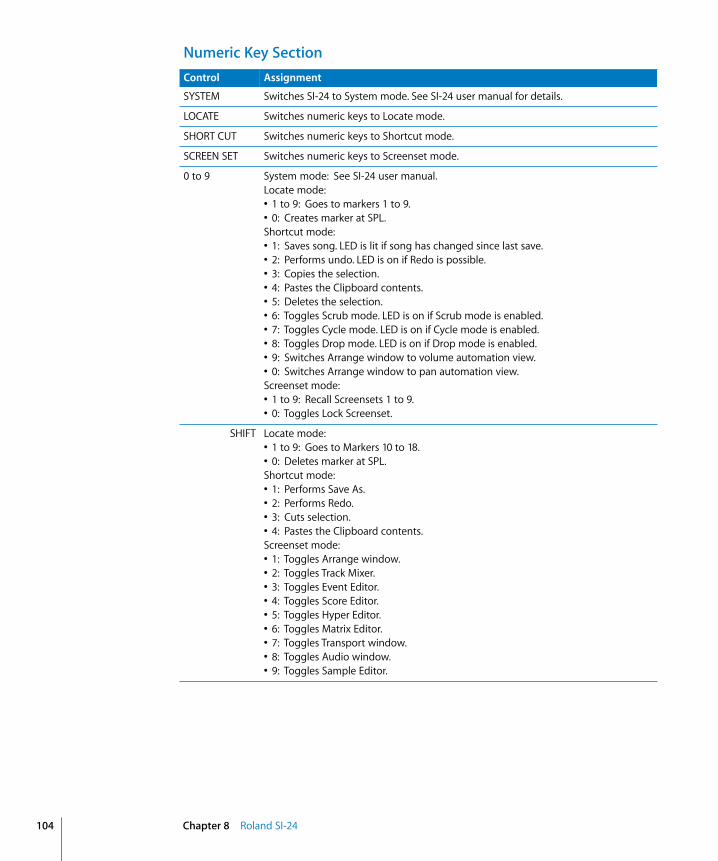
104
Numeric Key SectionControl Assignment
SYSTEM Switches SI-24 to System mode. See SI-24 user manual for details.
LOCATE Switches numeric keys to Locate mode.
SHORT CUT Switches numeric keys to Shortcut mode.
SCREEN SET Switches numeric keys to Screenset mode.
0 to 9 System mode: See SI-24 user manual.Locate mode:• 1 to 9: Goes to markers 1 to 9.• 0: Creates marker at SPL.Shortcut mode:• 1: Saves song. LED is lit if song has changed since last save.• 2: Performs undo. LED is on if Redo is possible.• 3: Copies the selection.• 4: Pastes the Clipboard contents.• 5: Deletes the selection.• 6: Toggles Scrub mode. LED is on if Scrub mode is enabled.• 7: Toggles Cycle mode. LED is on if Cycle mode is enabled.• 8: Toggles Drop mode. LED is on if Drop mode is enabled.• 9: Switches Arrange window to volume automation view.• 0: Switches Arrange window to pan automation view.Screenset mode:• 1 to 9: Recall Screensets 1 to 9.• 0: Toggles Lock Screenset.
SHIFT Locate mode:• 1 to 9: Goes to Markers 10 to 18.• 0: Deletes marker at SPL.Shortcut mode:• 1: Performs Save As.• 2: Performs Redo.• 3: Cuts selection.• 4: Pastes the Clipboard contents.Screenset mode:• 1: Toggles Arrange window.• 2: Toggles Track Mixer.• 3: Toggles Event Editor.• 4: Toggles Score Editor.• 5: Toggles Hyper Editor.• 6: Toggles Matrix Editor.• 7: Toggles Transport window.• 8: Toggles Audio window.• 9: Toggles Sample Editor.
Chapter 8 Roland SI-24
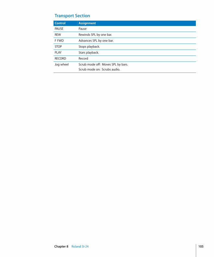
Transport SectionControl Assignment
PAUSE Pause
REW Rewinds SPL by one bar.
F FWD Advances SPL by one bar.
STOP Stops playback.
PLAY Stars playback.
RECORD Record
Jog wheel Scrub mode off: Moves SPL by bars.Scrub mode on: Scrubs audio.
Chapter 8 Roland SI-24 105


9
9 Tascam FW-1884IntroductionLogic Express 7 supports the Tascam FW-1884, FE-8 extension and the FW-1082.
Version 1.10 of the plug-in also supports the SoftLCD application which displays information on track names, parameter assignments and the current value of the encoders. SoftLCD displays the tracks’ current automation mode while one of the automation mode buttons is held down. The corresponding encoder edits the parameter.
Alerts are displayed in SoftLCD. Select buttons allow you to remotely-control alert buttons.
The following text referring to the FW-1884 also applies to FE-8 and FW-1082, except where mentioned explicitly.
Set UpPlease follow these steps before using your control surface with Logic Express 7.1.• Ensure that the FW-1884’s MIDI driver is installed. See the FW-1884 documentation
for details.• Connect the FW-1884 to your computer with the supplied FireWire cable.• Boot Logic Express 7.1. The FW-1884 is installed automatically.
Assignment OverviewA right-aligned modifier button (such as SHIFT) below a button description indicates that the button has an alternate meaning/use while holding down this modifier.
Note: The FE-8 units only offer the Channel Strip section, so other facilities mentioned here don’t apply. The FW-1884 ENCODERS section does, however, apply to the FE-8 channel strips.
The FW-1082 has no channel encoders, and offers an extended channel strip section.
107
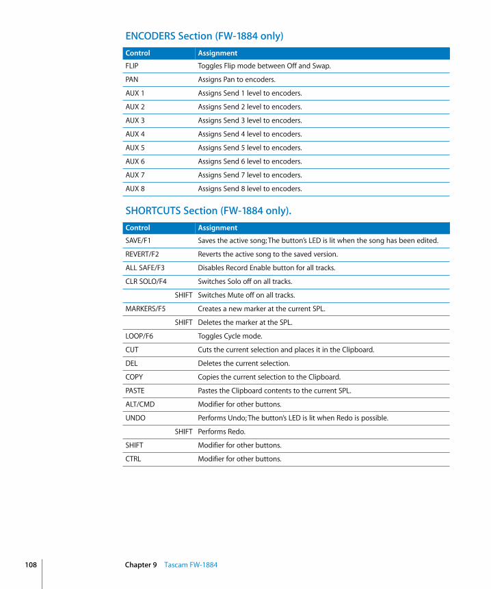
108
ENCODERS Section (FW-1884 only)
SHORTCUTS Section (FW-1884 only).
Control Assignment
FLIP Toggles Flip mode between Off and Swap.
PAN Assigns Pan to encoders.
AUX 1 Assigns Send 1 level to encoders.
AUX 2 Assigns Send 2 level to encoders.
AUX 3 Assigns Send 3 level to encoders.
AUX 4 Assigns Send 4 level to encoders.
AUX 5 Assigns Send 5 level to encoders.
AUX 6 Assigns Send 6 level to encoders.
AUX 7 Assigns Send 7 level to encoders.
AUX 8 Assigns Send 8 level to encoders.
Control Assignment
SAVE/F1 Saves the active song; The button’s LED is lit when the song has been edited.
REVERT/F2 Reverts the active song to the saved version.
ALL SAFE/F3 Disables Record Enable button for all tracks.
CLR SOLO/F4 Switches Solo off on all tracks.
SHIFT Switches Mute off on all tracks.
MARKERS/F5 Creates a new marker at the current SPL.
SHIFT Deletes the marker at the SPL.
LOOP/F6 Toggles Cycle mode.
CUT Cuts the current selection and places it in the Clipboard.
DEL Deletes the current selection.
COPY Copies the current selection to the Clipboard.
PASTE Pastes the Clipboard contents to the current SPL.
ALT/CMD Modifier for other buttons.
UNDO Performs Undo; The button’s LED is lit when Redo is possible.
SHIFT Performs Redo.
SHIFT Modifier for other buttons.
CTRL Modifier for other buttons.
Chapter 9 Tascam FW-1884
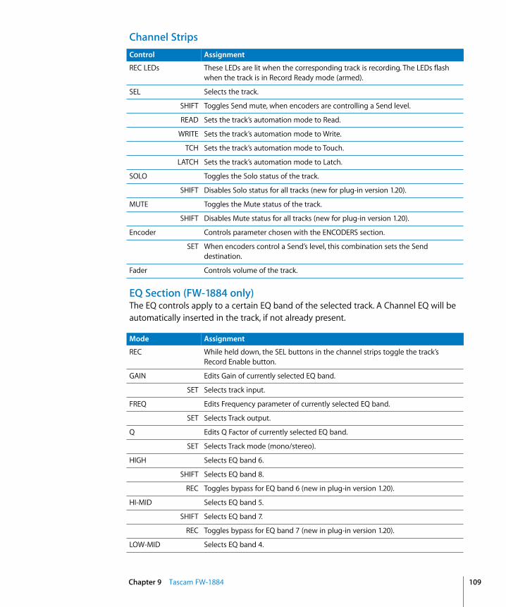
Channel Strips
EQ Section (FW-1884 only)The EQ controls apply to a certain EQ band of the selected track. A Channel EQ will be automatically inserted in the track, if not already present.
Control Assignment
REC LEDs These LEDs are lit when the corresponding track is recording. The LEDs flash when the track is in Record Ready mode (armed).
SEL Selects the track.
SHIFT Toggles Send mute, when encoders are controlling a Send level.
READ Sets the track’s automation mode to Read.
WRITE Sets the track’s automation mode to Write.
TCH Sets the track’s automation mode to Touch.
LATCH Sets the track’s automation mode to Latch.
SOLO Toggles the Solo status of the track.
SHIFT Disables Solo status for all tracks (new for plug-in version 1.20).
MUTE Toggles the Mute status of the track.
SHIFT Disables Mute status for all tracks (new for plug-in version 1.20).
Encoder Controls parameter chosen with the ENCODERS section.
SET When encoders control a Send’s level, this combination sets the Send destination.
Fader Controls volume of the track.
Mode Assignment
REC While held down, the SEL buttons in the channel strips toggle the track’s Record Enable button.
GAIN Edits Gain of currently selected EQ band.
SET Selects track input.
FREQ Edits Frequency parameter of currently selected EQ band.
SET Selects Track output.
Q Edits Q Factor of currently selected EQ band.
SET Selects Track mode (mono/stereo).
HIGH Selects EQ band 6.
SHIFT Selects EQ band 8.
REC Toggles bypass for EQ band 6 (new in plug-in version 1.20).
HI-MID Selects EQ band 5.
SHIFT Selects EQ band 7.
REC Toggles bypass for EQ band 7 (new in plug-in version 1.20).
LOW-MID Selects EQ band 4.
Chapter 9 Tascam FW-1884 109

110
Encoders and Controls Section (FW-1082 only)The three buttons at the bottom of this section define the mode of the other controls: • EQ/Pan mode: The controls apply to a certain EQ band of the selected track. • AUX 1–4 mode: The controls apply to Sends 1–4.• AUX 5–8 mode: The controls apply to Sends 5–8.
SHIFT Selects EQ band 2.
REC Toggles bypass for EQ band 3 (new in plug-in version 1.20).
LOW Selects EQ band 3.
SHIFT Selects EQ band 1.
REC Toggles bypass for EQ band 3 (new in plug-in version 1.20).
Mode Assignment
Mode Assignment
REC While held down, the SEL buttons in the channel strips toggle the track’s Record Enable button status.
EQ GAIN–AUX 1/5 • EQ/PAN mode: edits Gain of currently selected EQ band.• AUX 1–4 mode: controls Send 1 level.• AUX 5–8 mode: controls Send 5 level.
SET Selects Track input.
EQ FREQ–AUX 2/6 • EQ/PAN mode: edits Frequency of currently selected EQ band.• AUX 1–4 mode: controls Send 2 level.• AUX 5–8 mode: controls Send 6 level.
SET Selects Track output.
EQ Q–AUX 3/7 • EQ/PAN mode: edits Q Factor of currently selected EQ band.• AUX 1–4 mode: controls Send 3 level.• AUX 5–8 mode: controls Send 7 level.
SET Selects Track mode.
PAN–AUX 4/8 • EQ/PAN mode: edits Pan.• AUX 1–4 mode: controls Send 4 level.• AUX 5–8 mode: controls Send 8 level.
EQ HI–AUX 1/5 • EQ/PAN mode: selects EQ band 6.• AUX 1–4 mode: toggles Send 1 Mute.• AUX 5–8 mode: toggles Send 5 Mute.
SHIFT • EQ/PAN mode: selects EQ band 8.• AUX 1–4 mode: toggles Send 1 Position (pre/post.)• AUX 5–8 mode: toggles Send 5 Position (pre/post).
REC Toggles bypass for EQ band 6.
EQ HI MID–AUX 2/6 • EQ/PAN mode: selects EQ band 5.• AUX 1–4 mode: toggles Send 2 Mute.• AUX 5–8 mode: toggles Send 6 Mute.
Chapter 9 Tascam FW-1884

MASTER FaderThis fader always controls the master volume.
Automation/Clock Rate Section (FW-1884 only)
SHIFT • EQ/PAN mode: selects EQ band 7.• AUX 1–4 mode: toggles Send 2 Position (pre/post).• AUX 5–8 mode: toggles Send 6 Position (pre/post).
REC Toggles bypass for EQ band 5.
EQ LO MID–AUX 3/7 • EQ/PAN mode: selects EQ band 4.• AUX 1–4 mode: toggles Send 3 Mute.• AUX 5–8 mode: toggles Send 7 Mute.
SHIFT • EQ/PAN mode: selects EQ band 2.• AUX 1–4 mode: toggles Send 3 Position (pre/post).• AUX 5–8 mode: toggles Send 7 Position (pre/post).
REC Toggles bypass for EQ band 4.
EQ LOW–AUX 4/8 • EQ/PAN mode: selects EQ band 3.• AUX 1–4 mode: toggles Send 4 Mute.• AUX 5–8 mode: toggles Send 8 Mute
SHIFT • EQ/PAN mode: selects EQ band 1.• AUX 1–4 mode: toggles Send 4 Position (pre/post).• AUX 5–8 mode: toggles Send 8 Position (pre/post).
REC Toggles bypass for EQ band 3.
EQ/PAN Chooses EQ/PAN mode.
SHIFT Toggles Flip mode; With Flip mode enabled, the faders control Pan.
AUX 1–4 Chooses AUX 1–4 mode.
AUX 5–8 Chooses AUX 5–8 mode.
Mode Assignment
Control Assignment
READ While held down, SEL buttons are on if a track is in Read automation mode. Pressing the SEL button sets Read mode. Turning the encoder also edits the automation mode.
WRITE While held down, SEL buttons are on if a track is in Write automation mode. Pressing the SEL button sets Write mode. Turning the encoder also edits the automation mode.
TCH While held down, SEL buttons are on if a track is in Touch automation mode. Pressing the SEL button sets Touch mode. Turning the encoder also edits the automation mode.
LATCH While held down, SEL buttons are on if a track is in Latch automation mode. Pressing the SEL button sets Latch mode. Turning the encoder also edits the automation mode.
F7 Switches encoders to editing of pan.
Chapter 9 Tascam FW-1884 111

112
Mode Controls Section (FW-1082 only)
Master Section
F8 Switches encoders to EQ editing on selected track. See upper line on SoftLCD application for parameter assignment. Cursor left/right shifts the parameter bank.
F9 Switches encoders to plug-in editing on selected track. Cursor left/right shifts parameter bank; Cursor up/down chooses insert to edit.
F10 Switches encoders to instrument editing on selected track. Cursor left/right shifts parameter bank.
Control Assignment
Control Assignment
F1 Saves the active song; The button’s LED is lit if the song has been edited.
SHIFT Opens the Save As dialog.
F2 Performs Undo; The button’s LED is lit when Redo is possible.
SHIFT Performs Redo.
F3 Copies the current selection to the Clipboard.
SHIFT Cuts the current selection and places it in the Clipboard.
F4 Pastes the Clipboard contents.
SHIFT Clears the current selection.
Control Assignment
Cursor buttons Identical to computer keyboard’s Arrow keys—except when encoders are in EQ, Plug-in or Instrument Edit modes (see above).
SHIFT Zoom in and out horizontally or vertically.
SHTL Enables Shuttle mode for wheel.
Wheel Shuttle mode off: moves SPL by bar.Shuttle mode on: shuttles SPL.
Bank LEDs Show currently selected fader bank. If you only have an FW-1884, a bank refers to eight tracks. If you have FE-8 extensions added, a bank means the entire number of channel strips: 16, 24 and so on.If no LED is lit, a bank higher than 4 is selected.
< BANK Shifts fader bank down by one bank.
SHIFT Shifts fader bank down by one track.
SET Switches to Track view (new in plug-in version 1.20).
BANK > Shifts fader bank up by one bank.
SHIFT Shifts fader bank up by one track.
SET Switches to Global view and shows Aux, Bus and Output Objects (new in plug-in version 1.20).
<< LOCATE Goes to previous marker.
Chapter 9 Tascam FW-1884

SET Deletes the current marker (new in plug-in version 1.20).
LOCATE >> Goes to next marker.
SET Creates a new marker at the SPL (new in plug-in version 1.20).
SET Modifier for other buttons.
IN Goes to left locator.
SET Sets left locator to SPL.
SHIFT Sets Drop In locator to SPL.
OUT Goes to right locator.
SET Sets right locator to current SPL.
SHIFT Sets Drop Out locator to SPL.
REW Shuttle Rewind key command.
FFWD Shuttle Forward key command.
STOP Stops playback.
PLAY Starts playback.
REC Record key command.
Control Assignment
Chapter 9 Tascam FW-1884 113


10
10 Tascam US-2400Set UpPlease follow these steps before using your control surface with Logic Express 7.• Make sure that your US-2400 unit(s) are connected to the computer via USB.• Ensure that the US-2400 is in native mode.• With the US-2400 in standby (powered off ), simultaneously press and hold the
master SEL and AUX 5 keys.• While holding down these keys, turn on the US-2400 POWER key. Release the SEL
and AUX keys.• The AUX 5 key will flash three times to confirm the setting.• Launch Logic Express 7. Your control surface(s) will be scanned for, and installed,
automatically.
Assignment OverviewA right-aligned modifier button (such as SHIFT) below a button description indicates that the button has an alternate meaning/use while holding down this modifier.
Channel StripsControl Assignment
Encoder(s) CHAN button on: see “Encoder Details” on page 116.CHAN button flashing: Encoders control Instrument parameters, also see “Instrument Edit View” on page 118.PAN button flashing: Encoders control plug-in parameters, also see “Plug-in Edit View” on page 119.Other modes: Encoders control the mode’s parameters.
F-KEY • If you are in Instrument Edit view (CHAN button flashing), pressing the F-Key enters the Instrument Assignment view: The encoders then choose an instrument.
• If you are in Plug-in Edit view (PAN button flashing), pressing the F-Key enters the Plug-in Assignment view: the encoders then choose a plug-in.
• If you are in Send views (AUX button LED flashes) and press the F-Key, the encoders assign the send’s destination.
SEL buttons Select tracks.
115
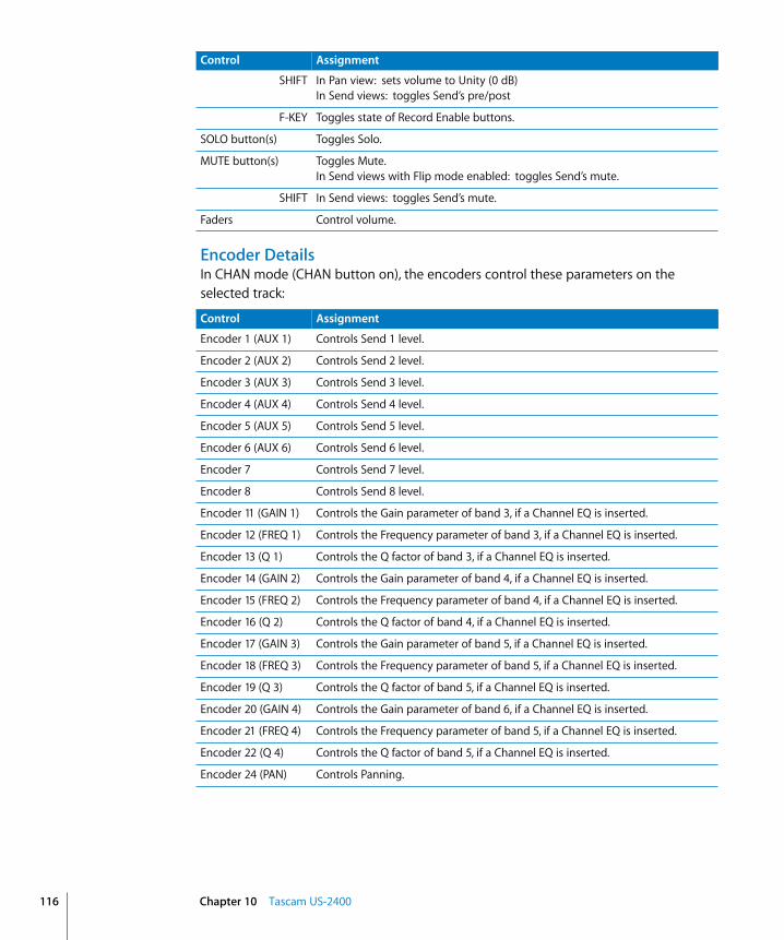
116
Encoder DetailsIn CHAN mode (CHAN button on), the encoders control these parameters on the selected track:
SHIFT In Pan view: sets volume to Unity (0 dB)In Send views: toggles Send’s pre/post
F-KEY Toggles state of Record Enable buttons.
SOLO button(s) Toggles Solo.
MUTE button(s) Toggles Mute.In Send views with Flip mode enabled: toggles Send’s mute.
SHIFT In Send views: toggles Send’s mute.
Faders Control volume.
Control Assignment
Control Assignment
Encoder 1 (AUX 1) Controls Send 1 level.
Encoder 2 (AUX 2) Controls Send 2 level.
Encoder 3 (AUX 3) Controls Send 3 level.
Encoder 4 (AUX 4) Controls Send 4 level.
Encoder 5 (AUX 5) Controls Send 5 level.
Encoder 6 (AUX 6) Controls Send 6 level.
Encoder 7 Controls Send 7 level.
Encoder 8 Controls Send 8 level.
Encoder 11 (GAIN 1) Controls the Gain parameter of band 3, if a Channel EQ is inserted.
Encoder 12 (FREQ 1) Controls the Frequency parameter of band 3, if a Channel EQ is inserted.
Encoder 13 (Q 1) Controls the Q factor of band 3, if a Channel EQ is inserted.
Encoder 14 (GAIN 2) Controls the Gain parameter of band 4, if a Channel EQ is inserted.
Encoder 15 (FREQ 2) Controls the Frequency parameter of band 4, if a Channel EQ is inserted.
Encoder 16 (Q 2) Controls the Q factor of band 4, if a Channel EQ is inserted.
Encoder 17 (GAIN 3) Controls the Gain parameter of band 5, if a Channel EQ is inserted.
Encoder 18 (FREQ 3) Controls the Frequency parameter of band 5, if a Channel EQ is inserted.
Encoder 19 (Q 3) Controls the Q factor of band 5, if a Channel EQ is inserted.
Encoder 20 (GAIN 4) Controls the Gain parameter of band 6, if a Channel EQ is inserted.
Encoder 21 (FREQ 4) Controls the Frequency parameter of band 5, if a Channel EQ is inserted.
Encoder 22 (Q 4) Controls the Q factor of band 5, if a Channel EQ is inserted.
Encoder 24 (PAN) Controls Panning.
Chapter 10 Tascam US-2400

In CHAN mode, with the SHIFT button held, the encoders control the following parameters on the selected track:
Master Channel
Encoder Assignment SectionThis is the standard assignment of these buttons:
Control Assignment
Encoder 1 (AUX 1) Controls Pan
Encoder 11 (GAIN 1) Controls the Slope parameter of band 1, if a Channel EQ is inserted.
Encoder 12 (FREQ 1) Controls the Frequency parameter of band 1, if a Channel EQ is inserted.
Encoder 13 (Q 1) Controls the Q factor of band 1, if a Channel EQ is inserted.
Encoder 14 (GAIN 2) Controls the Gain parameter of band 2, if a Channel EQ is inserted.
Encoder 15 (FREQ 2) Controls the Frequency parameter of band 2, if a Channel EQ is inserted.
Encoder 16 (Q 2) Controls the Q factor of band 2, if a Channel EQ is inserted.
Encoder 17 (GAIN 3) Controls the Gain parameter of band 7, if a Channel EQ is inserted.
Encoder 18 (FREQ 3) Controls the Frequency parameter of band 7, if a Channel EQ is inserted.
Encoder 19 (Q 3) Controls the Q factor of band 7, if a Channel EQ is inserted.
Encoder 20 (GAIN 4) Controls the Slope parameter of band 8, if a Channel EQ is inserted.
Encoder 21 (FREQ 4) Controls the Q factor of band 8, if a Channel EQ is inserted.
Encoder 22 (Q 4) Controls the Q factor of band 8, if a Channel EQ is inserted.
Encoder 24 (PAN) Controls Panning.
Control Assignment
SEL Selects Master Output track.
CLR SOLO Disables Solo for all tracks.
SHIFT Disables Mute for all tracks.
F-KEY Disables Record Enable button for all tracks.
FLIP Toggles Flip mode between Off (LED off ) and Duplicate (LED on).
SHIFT Sets Flip mode to Swap (LED flashing).
F-KEY Sets Flip mode to Zero—fader motors are disabled (LED flashing).
Control Assignment
CHAN Switches encoders to Channel Strip view (see encoders’ legend)—CHAN button LED is lit.
F-KEY Switches encoders to Instrument Edit view—CHAN button LED flashes. See “Instrument Edit View” on page 118 for details.
PAN Switches encoders to Multi Channel view of panning—PAN button LED is lit.
F-KEY Switches encoders to Plug-in Edit view—PAN button LED flashes. See “Plug-in Edit View” on page 119 for details.
Chapter 10 Tascam US-2400 117
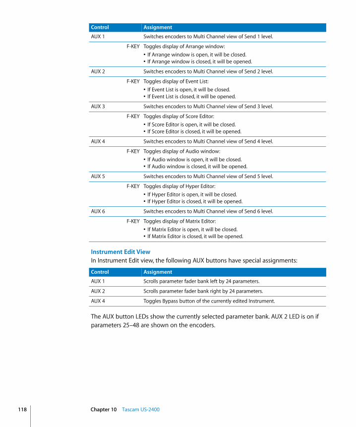
118
Instrument Edit ViewIn Instrument Edit view, the following AUX buttons have special assignments:
The AUX button LEDs show the currently selected parameter bank. AUX 2 LED is on if parameters 25–48 are shown on the encoders.
AUX 1 Switches encoders to Multi Channel view of Send 1 level.
F-KEY Toggles display of Arrange window: • If Arrange window is open, it will be closed.• If Arrange window is closed, it will be opened.
AUX 2 Switches encoders to Multi Channel view of Send 2 level.
F-KEY Toggles display of Event List:• If Event List is open, it will be closed.• If Event List is closed, it will be opened.
AUX 3 Switches encoders to Multi Channel view of Send 3 level.
F-KEY Toggles display of Score Editor:• If Score Editor is open, it will be closed.• If Score Editor is closed, it will be opened.
AUX 4 Switches encoders to Multi Channel view of Send 4 level.
F-KEY Toggles display of Audio window:• If Audio window is open, it will be closed.• If Audio window is closed, it will be opened.
AUX 5 Switches encoders to Multi Channel view of Send 5 level.
F-KEY Toggles display of Hyper Editor:• If Hyper Editor is open, it will be closed.• If Hyper Editor is closed, it will be opened.
AUX 6 Switches encoders to Multi Channel view of Send 6 level.
F-KEY Toggles display of Matrix Editor:• If Matrix Editor is open, it will be closed.• If Matrix Editor is closed, it will be opened.
Control Assignment
Control Assignment
AUX 1 Scrolls parameter fader bank left by 24 parameters.
AUX 2 Scrolls parameter fader bank right by 24 parameters.
AUX 4 Toggles Bypass button of the currently edited Instrument.
Chapter 10 Tascam US-2400
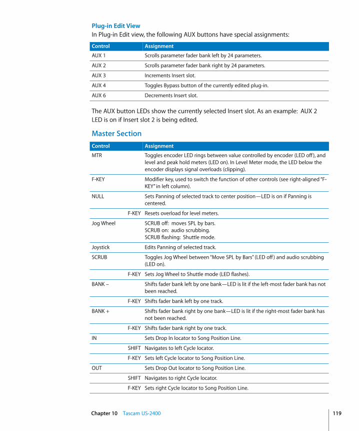
Plug-in Edit ViewIn Plug-in Edit view, the following AUX buttons have special assignments:
The AUX button LEDs show the currently selected Insert slot. As an example: AUX 2 LED is on if Insert slot 2 is being edited.
Master Section
Control Assignment
AUX 1 Scrolls parameter fader bank left by 24 parameters.
AUX 2 Scrolls parameter fader bank right by 24 parameters.
AUX 3 Increments Insert slot.
AUX 4 Toggles Bypass button of the currently edited plug-in.
AUX 6 Decrements Insert slot.
Control Assignment
MTR Toggles encoder LED rings between value controlled by encoder (LED off ), and level and peak hold meters (LED on). In Level Meter mode, the LED below the encoder displays signal overloads (clipping).
F-KEY Modifier key, used to switch the function of other controls (see right-aligned “F-KEY” in left column).
NULL Sets Panning of selected track to center position—LED is on if Panning is centered.
F-KEY Resets overload for level meters.
Jog Wheel SCRUB off: moves SPL by bars.SCRUB on: audio scrubbing.SCRUB flashing: Shuttle mode.
Joystick Edits Panning of selected track.
SCRUB Toggles Jog Wheel between “Move SPL by Bars” (LED off ) and audio scrubbing (LED on).
F-KEY Sets Jog Wheel to Shuttle mode (LED flashes).
BANK – Shifts fader bank left by one bank—LED is lit if the left-most fader bank has not been reached.
F-KEY Shifts fader bank left by one track.
BANK + Shifts fader bank right by one bank—LED is lit if the right-most fader bank has not been reached.
F-KEY Shifts fader bank right by one track.
IN Sets Drop In locator to Song Position Line.
SHIFT Navigates to left Cycle locator.
F-KEY Sets left Cycle locator to Song Position Line.
OUT Sets Drop Out locator to Song Position Line.
SHIFT Navigates to right Cycle locator.
F-KEY Sets right Cycle locator to Song Position Line.
Chapter 10 Tascam US-2400 119
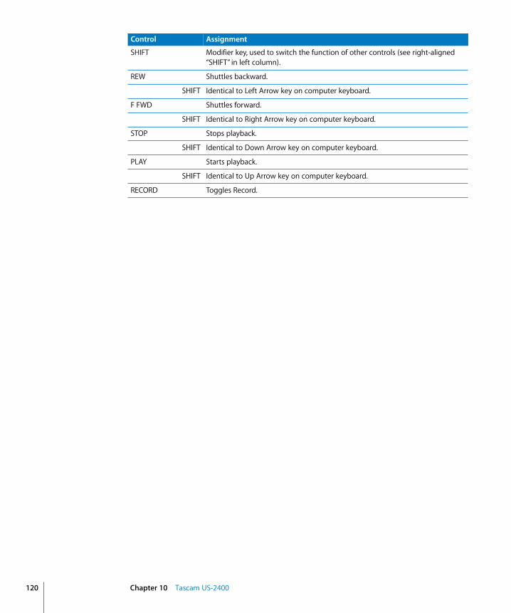
120
SHIFT Modifier key, used to switch the function of other controls (see right-aligned “SHIFT” in left column).
REW Shuttles backward.
SHIFT Identical to Left Arrow key on computer keyboard.
F FWD Shuttles forward.
SHIFT Identical to Right Arrow key on computer keyboard.
STOP Stops playback.
SHIFT Identical to Down Arrow key on computer keyboard.
PLAY Starts playback.
SHIFT Identical to Up Arrow key on computer keyboard.
RECORD Toggles Record.
Control Assignment
Chapter 10 Tascam US-2400
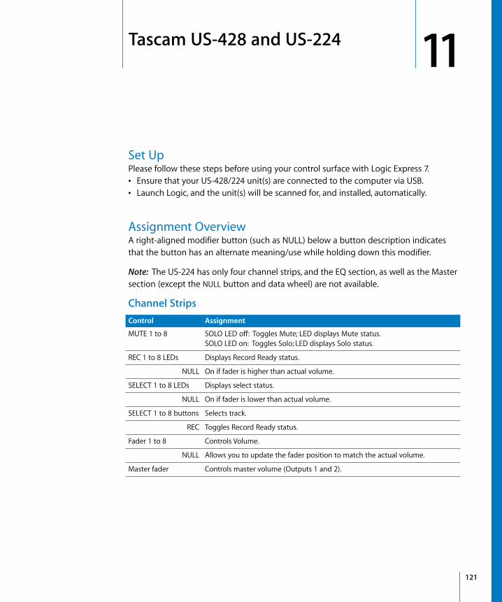
11
11 Tascam US-428 and US-224Set UpPlease follow these steps before using your control surface with Logic Express 7.• Ensure that your US-428/224 unit(s) are connected to the computer via USB. • Launch Logic, and the unit(s) will be scanned for, and installed, automatically.
Assignment OverviewA right-aligned modifier button (such as NULL) below a button description indicates that the button has an alternate meaning/use while holding down this modifier.
Note: The US-224 has only four channel strips, and the EQ section, as well as the Master section (except the NULL button and data wheel) are not available.
Channel StripsControl Assignment
MUTE 1 to 8 SOLO LED off: Toggles Mute; LED displays Mute status.SOLO LED on: Toggles Solo; LED displays Solo status.
REC 1 to 8 LEDs Displays Record Ready status.
NULL On if fader is higher than actual volume.
SELECT 1 to 8 LEDs Displays select status.
NULL On if fader is lower than actual volume.
SELECT 1 to 8 buttons Selects track.
REC Toggles Record Ready status.
Fader 1 to 8 Controls Volume.
NULL Allows you to update the fader position to match the actual volume.
Master fader Controls master volume (Outputs 1 and 2).
121

122
EQ Section
Master Section Controls
Control Assignment
Gain Controls gain of currently selected EQ of chosen track.
Freq Controls frequency of currently selected EQ of chosen track.
Q Controls Q factor of currently selected EQ of chosen track.
HIGH Selects EQ band 3 for Gain, Freq and Q controls.
ASGN Toggles EQ band 3 bypass.
HI-MID Selects EQ band 4 for Gain, Freq and Q controls.
ASGN Toggles EQ band 4 bypass.
LO-MID Selects EQ band 5 for Gain, Freq and Q controls.
ASGN Toggles EQ band 5 bypass.
LOW Selects EQ band 6 for Gain, Freq and Q controls.
ASGN Toggles EQ band 6 bypass.
Control Assignment
AUX 1 Toggles data wheel between Transport/Scrub mode and Send Level 1.
ASGN Toggles Send 1 Mute.
AUX 2 Toggles data wheel between Transport/Scrub mode and Send Level 2.
ASGN Toggles Send 2 Mute.
AUX 3 Toggles data wheel between Transport/Scrub mode and Send Level 3.
ASGN Toggles Send 3 Mute.
AUX 4 Toggles data wheel between Transport/Scrub mode and Send Level 4.
ASGN Toggles Send 4 Mute.
ASGN Modifier for function of EQ controls, AUX 1 to 4 buttons, PAN knob and data wheel.
F1 Toggles Cycle mode.
F2 Toggles Drop mode.
F3 Toggles Scrub mode.
PAN Controls panning of selected track.
ASGN Selects current track’s input.
NULL Modifier for NULL mode. NULL mode allows you to update the fader positions to match the actual volume.
Chapter 11 Tascam US-428 and US-224
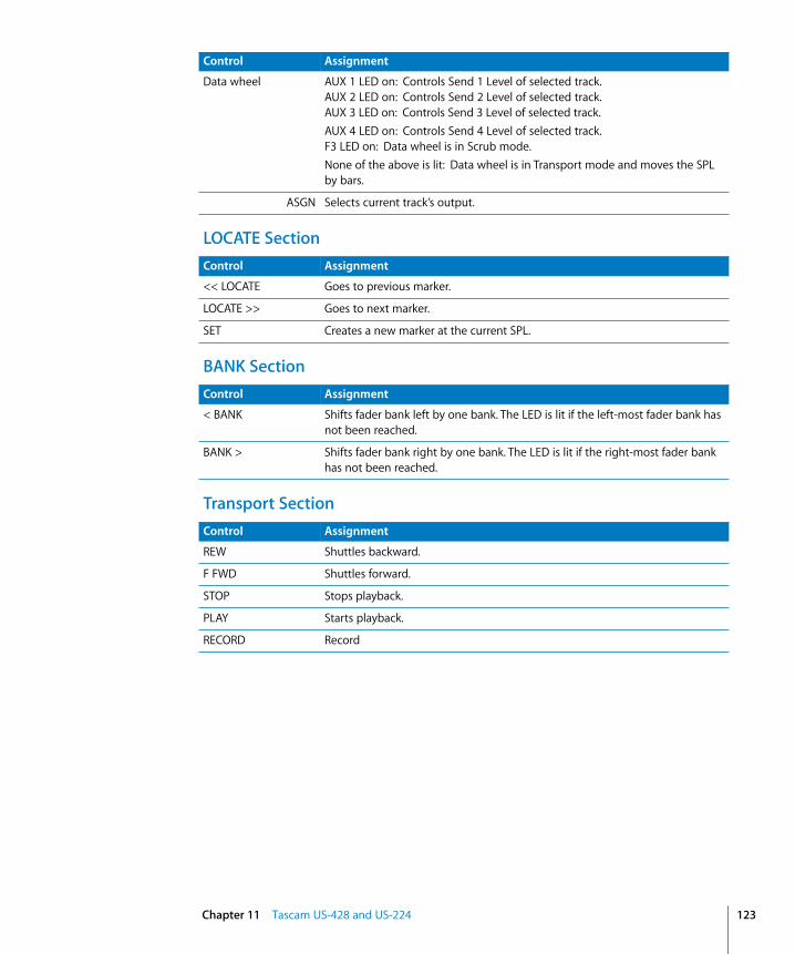
LOCATE Section
BANK Section
Transport Section
Data wheel AUX 1 LED on: Controls Send 1 Level of selected track.AUX 2 LED on: Controls Send 2 Level of selected track.AUX 3 LED on: Controls Send 3 Level of selected track.AUX 4 LED on: Controls Send 4 Level of selected track.F3 LED on: Data wheel is in Scrub mode.None of the above is lit: Data wheel is in Transport mode and moves the SPL by bars.
ASGN Selects current track’s output.
Control Assignment
Control Assignment
<< LOCATE Goes to previous marker.
LOCATE >> Goes to next marker.
SET Creates a new marker at the current SPL.
Control Assignment
< BANK Shifts fader bank left by one bank. The LED is lit if the left-most fader bank has not been reached.
BANK > Shifts fader bank right by one bank. The LED is lit if the right-most fader bank has not been reached.
Control Assignment
REW Shuttles backward.
F FWD Shuttles forward.
STOP Stops playback.
PLAY Starts playback.
RECORD Record
Chapter 11 Tascam US-428 and US-224 123


App
endi
x
A
A Logic Control—SpecificationsLogic Control (Base Unit)This appendix describes the specifications of the Logic Control unit.
Display• 55 × 2-digit (LCD) backlit multi-function display for detailed parameter information
and metering• Built-in screensaver function • 2-digit, 7-segment display for mode displays• 10-digit, 7-segment display for song position information in either SMPTE or bar/
beats/ticks• 1 × button to toggle the LCD between parameter name/value and to activate the
level meters. • 1 × button to toggle the 7-segment display between SMPTE and bar/beats/ticks. • 2 × LEDs show the current 7-segment display status. • 1 × LED shows the current Solo status.
Per Channel (8 Channels)• 1 × motorized 100mm touch-sensitive Penny & Giles faders with 10Bit resolution
(1024 steps)• 1 × V-POT: digital endless rotary knob with position indicator and integrated push
button for parameter adjustments of pan, EQ, send levels and so on• 4 × buttons with integrated colored LED for channel functions such as: Record, Solo,
Mute and Channel Selection • Signal Present LED indicates when an audio or MIDI signal is present.
Master Fader• 1 × motorized 100mm touch-sensitive Penny & Giles fader with 10Bit resolution (1024
steps).
Controller• 6 × buttons with status LED for direct selection of parameter groups for Track, Pan/
Surround, EQ, Send, Plug-In, Instrument • 8 × buttons to directly select sections of Logic’s mixer such as audio tracks, MIDI
tracks, inputs, busses and so on
125
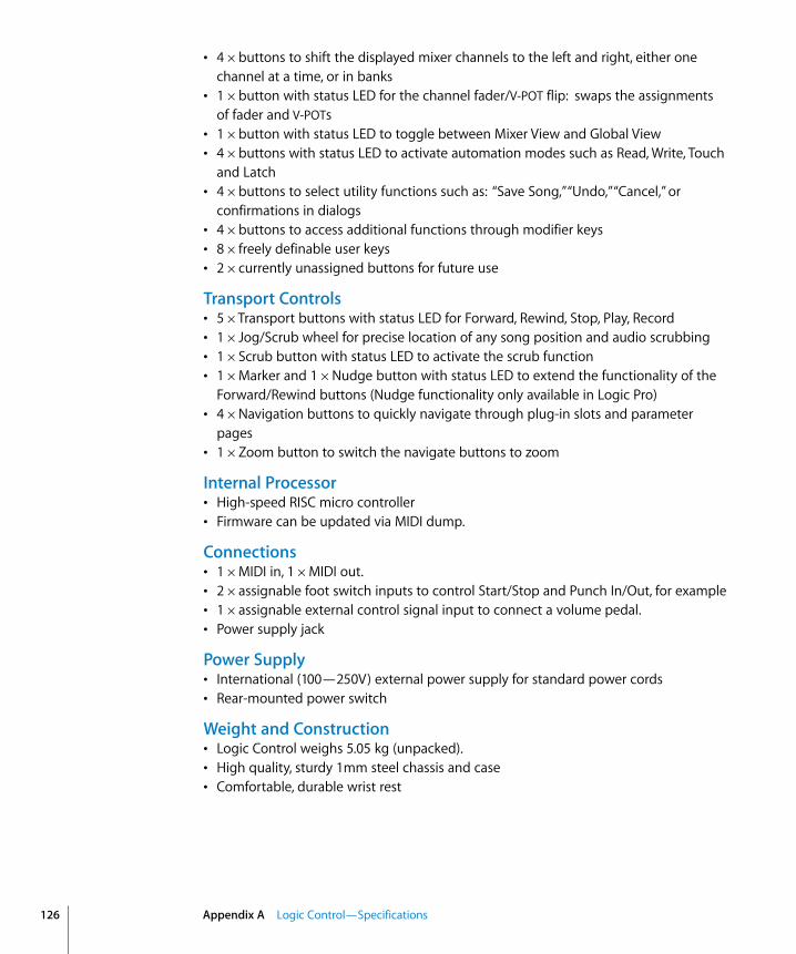
126
• 4 × buttons to shift the displayed mixer channels to the left and right, either one channel at a time, or in banks
• 1 × button with status LED for the channel fader/V-POT flip: swaps the assignments of fader and V-POTs
• 1 × button with status LED to toggle between Mixer View and Global View• 4 × buttons with status LED to activate automation modes such as Read, Write, Touch
and Latch• 4 × buttons to select utility functions such as: “Save Song,” “Undo,” “Cancel,” or
confirmations in dialogs• 4 × buttons to access additional functions through modifier keys• 8 × freely definable user keys• 2 × currently unassigned buttons for future use
Transport Controls• 5 × Transport buttons with status LED for Forward, Rewind, Stop, Play, Record• 1 × Jog/Scrub wheel for precise location of any song position and audio scrubbing • 1 × Scrub button with status LED to activate the scrub function• 1 × Marker and 1 × Nudge button with status LED to extend the functionality of the
Forward/Rewind buttons (Nudge functionality only available in Logic Pro)• 4 × Navigation buttons to quickly navigate through plug-in slots and parameter
pages• 1 × Zoom button to switch the navigate buttons to zoom
Internal Processor • High-speed RISC micro controller• Firmware can be updated via MIDI dump.
Connections • 1 × MIDI in, 1 × MIDI out.• 2 × assignable foot switch inputs to control Start/Stop and Punch In/Out, for example• 1 × assignable external control signal input to connect a volume pedal.• Power supply jack
Power Supply • International (100—250V) external power supply for standard power cords• Rear-mounted power switch
Weight and Construction• Logic Control weighs 5.05 kg (unpacked). • High quality, sturdy 1mm steel chassis and case • Comfortable, durable wrist rest
Appendix A Logic Control—Specifications

Dimensions
Logic Control XT (Extension Unit)Display • 55 × 2-digit (LCD) backlit multi-function display for detailed parameter information
and metering • Built-in screensaver function
Per channel (8 channels)• 1 × motorized 100mm touch-sensitive Penny & Giles faders with 10Bit resolution
(1024 steps) • 1 × V-POT: digital endless rotary knob with position indicator and integrated push
button for parameter adjustments of pan, EQ, send levels, and so on• 4 × buttons with integrated colored LED for channel functions such as: Record, Solo,
Mute and Channel Selection• Signal Present LED indicates the presence of an audio signal
Internal Processor• High-speed RISC micro controller• Firmware can be updated via MIDI dump.
Connections• 1 × MIDI in, 1 × MIDI out• Power supply jack
Power Supply • International (100—250V) external power supply for standard power cords• Rear-mounted power switch
Weight and Construction • Logic Control XT weighs 3.45 kg (unpacked) • High quality, sturdy 1mm steel chassis and case• Comfortable, durable wrist rest
Appendix A Logic Control—Specifications 127

128
Dimensions
Appendix A Logic Control—Specifications

App
endi
x
B
B Logic Control—MIDI ImplementationThe following information is important for software vendors who wish to create a level of software integration for the Logic/Mackie Control/XT units.
This documentation covers firmware version V1.0.
Note: All numbers are in hexadecimal format.
Variable bytes are shown in italics and use characters other than a-f as a placeholder.
All channel messages use running status messages. Once an initial 3-byte message has been sent, the status byte is dropped from proceeding transmitted channel messages, in order to conserve bandwidth.
SysEx Message HeaderThe following documentation uses the place holder “<Hdr>” whenever the SysEx header is transmitted or received. It has the following form:
F0 MIDI SysEx status byte00 00 66 Mackie 3-byte SysEx manufacturer IDii Model ID
10 Logic Control11 Logic Control XT
A device ID is not required, as each unit needs a dedicated MIDI cable.
129

130
Global Control MessagesHost Connection and Initialization
Received:<Hdr> 00 F7
Device Query<Hdr> 02 ss ss ss ss ss ss ss rr rr rr rr F7
Host Connection Reply<Hdr> 0F 7F F7
Go OfflineTransmitted:
<Hdr> 01 ss ss ss ss ss ss ss ll ll ll ll F7Host Connection Query
<Hdr> 03 ss ss ss ss ss ss ss F7Host Connection Confirmation
<Hdr> 04 ss ss ss ss ss ss ss F7Host Connection Error
ss = Serial number (7 bytes ASCII text, non null-terminated)ll = Challenge code (4 bytes)rr = Response code (4 bytes)
Offline Mode:Logic Control employs a query system to maintain a connection to the host software. When Logic Control is initially powered up, it defaults to Offline mode. In Offline mode, Logic Control’s faders move to their lowest setting, and the LCD reads “EMAGIC LOGIC CONTROL -- by MACKIE.” After power-on, Logic Control also transmits a system exclusive Host Connection Query message that is used (by the host) to detect a connection, and what type of device is connected (Logic Control/Logic Control XT).
Communications Initialization:When the host software receives a Host Connection Query message (containing a serial number and a random challenge code), it should transmit a Host Connection Reply command within 300ms to initialize Logic Control. The command must contain the same serial number and the correct response code for the challenge code. Here is the algorithm (l1 to l4 = challenge code bytes 1 to 4, r1 to r4 = response code bytes 1 to 4):
r1 = 0x7F & (l1 + (l2 ^ 0xa) - l4);r2 = 0x7F & ((l3>>4) ^ (l1+l4));r3 = 0x7F & ( l4-(l3<<2) ^ (l1|l2));r4 = 0x7F & (l2-l3+(0xF0^(l4<<4)));
Logic Control will, in turn, respond with either: • a Host Connection Confirmation message that contains the serial number, and switch
to Online mode—where it will await further instructions from the host, or • reply with a Host Connection Error message, if the response code was wrong.
Appendix B Logic Control—MIDI Implementation

Online Mode:Once the connection between Logic Control and the host software has been made, Logic Control stays in Online Mode until it receives a Go Offline message.
Firmware version requestReceived:
<Hdr> 13 00 F7 Version requestTransmitted:
<Hdr> 14 vv vv vv vv vv F7 Version replyvv 5 ASCII bytes containing version string, e.g. “V1.0”.
Note: When Logic Control receives a version request message, it sends the version reply message.
Reset MessagesReceived:
<Hdr> 61 F7 Faders to minimum(Sends all faders to the bottom of their throw)
<Hdr> 62 F7 All LEDs off(Turns off all LEDs on Logic Control)
<Hdr> 63 F7 Reset(Re-Boots Logic Control into Offline mode)
Transmitted: No
Configuration MessagesReceived:
<Hdr> 0A tt F7 Transport button click<Hdr> 0B ll F7 LCD back light saver<Hdr> 0C mm F7 Touchless movable faders<Hdr> 0E ii ss F7 Fader touch sensitivity
Transmitted: Nott 00 = no transport button click
01 = transport button click (default)ll 00 = LCD back light off
01 to 7F = LCD back light on, with time out in minutes (default: 0F = 15 minutes)
mm 00 = fader movements are only transmitted if the fader has been recognized as touched01 = fader movements are also transmitted if the fader has not been recog-nized as touched (e.g. with fingernail or pen)
ii Fader ID (00 thru 07; Master = 08)ss Fader touch sensitivity (00 to 05; default: 03)
Appendix B Logic Control—MIDI Implementation 131

132
Common Control MessagesFaders
Received: Ei, ll, hh Move fader to positionTransmitted: Ei, ll, hh Fader moved by useri Fader ID (00 thru 07; Master = 08)ll Fader position value low 7 bits(00–7F)hh Fader position value high 7 bits (00–7F)Example: E0, 40, 55 = Fader Ch. 1, position (55 << 7) + 40
Note: Message format for transmitted fader position is the same as for received position. Only the top (high) 10 of the 14 transmitted bits are required. Positions 0 to 1023 (decimal) are transmitted as 0000 to 03FF (Ei 00 00 to Ei 7F 7F).
SwitchesReceived: NoneTransmitted: 90, ii, ss Switch pressed/released by userii Switch ID (See Logic Control—Control Surface Layout and IDs section on page
141)ss Switch State
00 = switch or fader released7F = switch pressed or fader touched
Example: 90, 0F, 7F = SOLO Ch. 8 is pressed90, 0F, 00 = SOLO Ch. 8 is released
Note: LEDs and switches use the same control message. This approach means that an LED has the same ID as its corresponding switch.
LEDsReceived: 90, ii, ss Set LED statusTransmitted: Noneii LED ID (See Logic Control—Control Surface Layout and IDs section on page
141)ss LED State (7F = on, 00 = off, 01 = flashing)Example: 90, 08, 7F = Turn LED 08 on
90, 08, 00 = Turn LED 08 off
Note: Switches and LEDs use the same control message. This ensures that an LED always shares an ID with its corresponding switch.
Appendix B Logic Control—MIDI Implementation
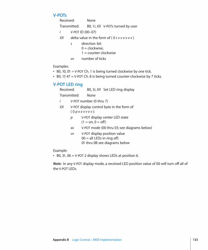
V-POTsReceived: NoneTransmitted: B0, 1i, XX V-POTs turned by useri V-POT ID (00–07)XX delta value in the form of ( 0 s v v v v v v )
s direction bit: 0 = clockwise,1 = counter clockwise
vv number of ticks
Examples:• B0, 10, 01 = V-POT Ch. 1 is being turned clockwise by one tick.• B0, 17, 47 = V-POT Ch. 8 is being turned counter-clockwise by 7 ticks.
V-POT LED ringReceived: B0, 3i, XX Set LED ring displayTransmitted: Nonei V-POT number (0 thru 7)XX V-POT display control byte in the form of
( 0 p x x v v v v ):p V-POT display center LED state
(1 = on, 0 = off )xx V-POT mode (00 thru 03; see diagrams below)vv V-POT display position value
00 = all LEDs in ring off;01 thru 0B see diagrams below
Example:• B0, 31, 06 = V-POT 2 display shows LEDs at position 6.
Note: In any V-POT display mode, a received LED position value of 00 will turn off all of the V-POT LEDs.
Appendix B Logic Control—MIDI Implementation 133

134
V-POT Display modes available:
Appendix B Logic Control—MIDI Implementation
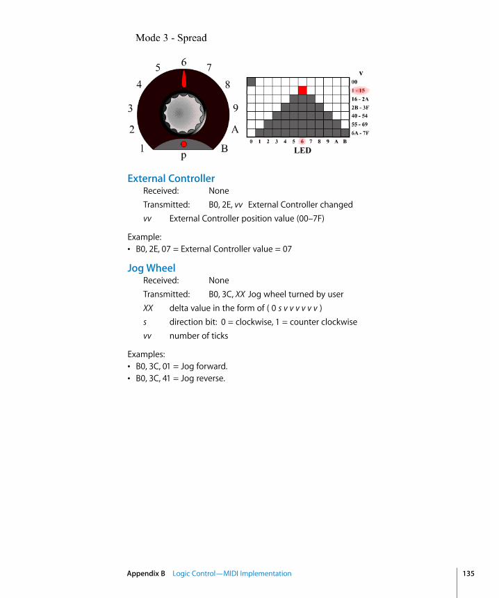
External ControllerReceived: NoneTransmitted: B0, 2E, vv External Controller changedvv External Controller position value (00–7F)
Example:• B0, 2E, 07 = External Controller value = 07
Jog WheelReceived: NoneTransmitted: B0, 3C, XX Jog wheel turned by userXX delta value in the form of ( 0 s v v v v v v )s direction bit: 0 = clockwise, 1 = counter clockwisevv number of ticks
Examples:• B0, 3C, 01 = Jog forward.• B0, 3C, 41 = Jog reverse.
Appendix B Logic Control—MIDI Implementation 135

136
LCDReceived: <Hdr>, 12, oo, yy, …, F7 Update LCDTransmitted: Noneoo Display offset to write from:
00 thru 37 for upper line,38 thru 6F for lower line.
yy Data: ASCII equivalents for display characters—written from left to right—and including line wrapping between upper and lower lines. Up to 100 data bytes may be sent in one message.
Example:• The following message writes “Hello” to the top left of the LCD on a Logic Control
master section.F0 00 00 66 10 12 00 48 65 6C 6C 6F F7
Notes:• There are 7 displayed characters per channel, with the exception of channel 8, which
is limited to displaying the first 6 characters. Internally however, the LCD stores 2 x 56 characters.
• In most cases, you will use the LCD in a scribble-strip fashion (text above each channel). In this scenario, you should only use the first six characters per channel, thus allowing for spaces between the text of each channel.
• The lower line can be switched into meter mode. See Metering section on page 139 for further details.
• While the LCD switches between horizontal and vertical metering modes, it ignores LCD messages. You should delay LCD messages for at least 600 ms after sending an LCD metering mode change message.
Appendix B Logic Control—MIDI Implementation

Time Code/BBT DisplayReceived:
<Hdr>, 10, yy, …, F7 Update multiple charactersB0, 4i, yy Update single character
Transmitted: Nonei Digit ID: 0 = right-most, 9 = left-mostyy Data bytes representing character to be written (See 7-Segment Display Char-
acter Table section on page 138). Up to ten characters can be sent in the SysEx message.
Examples:• The following message writes “109.02.01.126” to the Time Code display (note decimal
points).F0 00 00 66 10 10 36 32 31 71 30 72 30 79 30 31 F7
• B0 40 30 41 31 = writes “10” into the last two digits.
Important: The digits in the Time Code and Assignment displays are written RIGHT-TO-LEFT, which helps to conserve bandwidth.
Assignment 7-segment displayReceived:
<Hdr>, 11, yy, yy, F7 Update multiple charactersB0, 4i, yy Update single character
Transmitted: Nonei Digit ID: A= right, B = leftyy Data bytes representing character to be written (See 7-Segment Display Char-
acter Table section on page 138). Two characters can be sent in the SysEx message.
Example:• B0 4B 10 4A 4E = writes “Pn.” to the Assignment display.
Important: The digits in the Time Code and Assignment displays are written RIGHT-TO-LEFT, to help conserve bandwidth.
Appendix B Logic Control—MIDI Implementation 137
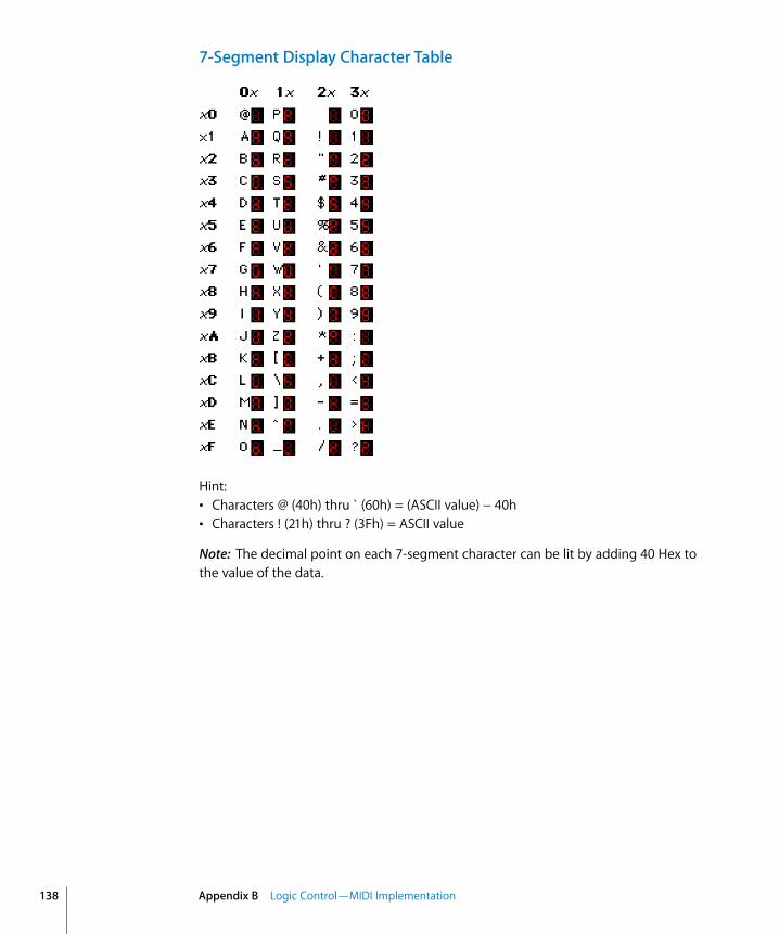
138
7-Segment Display Character Table
Hint:• Characters @ (40h) thru ` (60h) = (ASCII value) − 40h• Characters ! (21h) thru ? (3Fh) = ASCII value
Note: The decimal point on each 7-segment character can be lit by adding 40 Hex to the value of the data.
Appendix B Logic Control—MIDI Implementation
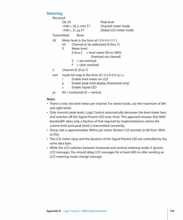
MeteringReceived:
D0, XX Peak level<Hdr>, 20, ii, mm, F7 Channel meter mode<Hdr>, 21, yy, F7 Global LCD meter mode
Transmitted: NoneXX Meter level in the form of ( 0 h h h l l l l ):
hh Channel to be addressed (0 thru 7)ll Meter level:
0 thru C = level meter 0% to 100%Overload not cleared!
E = set overloadF = clear overload
ii Channel ID (0 to 7)mm mode bit map in the form of ( 0 0 0 0 0 l p s ):
l Enable level meter on LCDp Enable peak hold display (horizontal only)s Enable Signal LED
yy 00 = horizontal; 01 = vertical
Notes:• There is only one level meter per channel. For stereo tracks, use the maximum of left
and right levels.• Only transmit peak levels. Logic Control automatically decreases the level meter bars,
and switches off the Signal Present LED (over time). This approach ensures that MIDI bandwidth takes only a fraction of that required by implementations where the current level (and peak level) is transmitted constantly.
• Decay rate is approximately 300ms per meter division (1.8 seconds to fall from 100% to 0%).
• The LCD meter value and the duration of the Signal Present LED are controlled by the same data byte.
• While the LCD switches between horizontal and vertical metering mode, it ignores LCD messages. You should delay LCD messages for at least 600 ms after sending an LCD metering mode change message.
Appendix B Logic Control—MIDI Implementation 139


App
endi
x
C
C Logic Control—Control Surface Layout and IDsID Switch LED Function
00 • • REC/RDY Ch. 1
01 • • REC/RDY Ch. 2
02 • • REC/RDY Ch. 3
03 • • REC/RDY Ch. 4
04 • • REC/RDY Ch. 5
05 • • REC/RDY Ch. 6
06 • • REC/RDY Ch. 7
07 • • REC/RDY Ch. 8
08 • • SOLO Ch. 1
09 • • SOLO Ch. 2
0A • • SOLO Ch. 3
0B • • SOLO Ch. 4
0C • • SOLO Ch. 5
0D • • SOLO Ch. 6
0E • • SOLO Ch. 7
0F • • SOLO Ch. 8
10 • • MUTE Ch. 1
11 • • MUTE Ch. 2
12 • • MUTE Ch. 3
13 • • MUTE Ch. 4
14 • • MUTE Ch. 5
15 • • MUTE Ch. 6
16 • • MUTE Ch. 7
17 • • MUTE Ch. 8
18 • • SELECT Ch. 1
19 • • SELECT Ch. 2
141

142
1A • • SELECT Ch. 3
1B • • SELECT Ch. 4
1C • • SELECT Ch. 5
1D • • SELECT Ch. 6
1E • • SELECT Ch. 7
1F • • SELECT Ch. 8
20 • V-Select Ch. 1
21 • V-Select Ch. 2
22 • V-Select Ch. 3
23 • V-Select Ch. 4
24 • V-Select Ch. 5
25 • V-Select Ch. 6
26 • V-Select Ch. 7
27 • V-Select Ch. 8
28 • • ASSIGNMENT: TRACK
29 • • ASSIGNMENT: SEND
2A • • ASSIGNMENT: PAN/SURROUND
2B • • ASSIGNMENT: PLUG-IN
2C • • ASSIGNMENT: EQ
2D • • ASSIGNMENT: INSTRUMENT
2E • FADER BANKS: BANK Left
2F • FADER BANKS: BANK Right
30 • FADER BANKS: CHANNEL Left
31 • FADER BANKS: CHANNEL Right
32 • • FLIP
33 • • GLOBAL VIEW
34 • NAME/VALUE
35 • SMPTE/BEATS
36 • F1
37 • F2
38 • F3
39 • F4
3A • F5
3B • F6
3C • F7
3D • F8
ID Switch LED Function
Appendix C Logic Control—Control Surface Layout and IDs
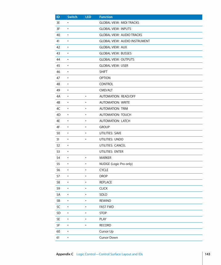
3E • GLOBAL VIEW: MIDI TRACKS
3F • GLOBAL VIEW: INPUTS
40 • GLOBAL VIEW: AUDIO TRACKS
41 • GLOBAL VIEW: AUDIO INSTRUMENT
42 • GLOBAL VIEW: AUX
43 • GLOBAL VIEW: BUSSES
44 • GLOBAL VIEW: OUTPUTS
45 • GLOBAL VIEW: USER
46 • SHIFT
47 • OPTION
48 • CONTROL
49 • CMD/ALT
4A • • AUTOMATION: READ/OFF
4B • • AUTOMATION: WRITE
4C • • AUTOMATION: TRIM
4D • • AUTOMATION: TOUCH
4E • • AUTOMATION: LATCH
4F • • GROUP
50 • • UTILITIES: SAVE
51 • • UTILITIES: UNDO
52 • UTILITIES: CANCEL
53 • UTILITIES: ENTER
54 • • MARKER
55 • • NUDGE (Logic Pro only)
56 • • CYCLE
57 • • DROP
58 • • REPLACE
59 • • CLICK
5A • • SOLO
5B • • REWIND
5C • • FAST FWD
5D • • STOP
5E • • PLAY
5F • • RECORD
60 • Cursor Up
61 • Cursor Down
ID Switch LED Function
Appendix C Logic Control—Control Surface Layout and IDs 143
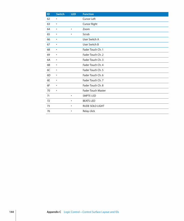
144
62 • Cursor Left
63 • Cursor Right
64 • • Zoom
65 • • Scrub
66 • User Switch A
67 • User Switch B
68 • Fader Touch Ch. 1
69 • Fader Touch Ch. 2
6A • Fader Touch Ch. 3
6B • Fader Touch Ch. 4
6C • Fader Touch Ch. 5
6D • Fader Touch Ch. 6
6E • Fader Touch Ch. 7
6F • Fader Touch Ch. 8
70 • Fader Touch Master
71 • SMPTE LED
72 • BEATS LED
73 • RUDE SOLO LIGHT
76 • Relay click
ID Switch LED Function
Appendix C Logic Control—Control Surface Layout and IDs

App
endi
x
D
D Logic Control—MIDI Implementation ChartMode 1: OMNI ON, POLY, Mode 2: OMNI ON, MONO, O: YesMode 3: OMNI OFF, POLY, Mode 4: OMNI OFF, MONO, X: No
Function Transmitted Recognized Remarks
Channel, Default:Changed:
11
11
Each Logic Control unit should be installed on a separate MIDI port.
Mode, Default:Messages:Altered:
XXX
XXX
Note NumberTrue Voice:
O 0–127X
O 0–127X
Velocity, Note On:Note Off:
O v = 1–127X v = 00
O v = 1–127X v = 00
After Touch, Keys:Chan’s:
XX
XO
Pitch Bend O O Used for motor faders
Control Change O O
Program ChangeTrue #:
X X
SYSTEM EXCLUSIVE:
O O
SYSTEM COMMON:
X X
145

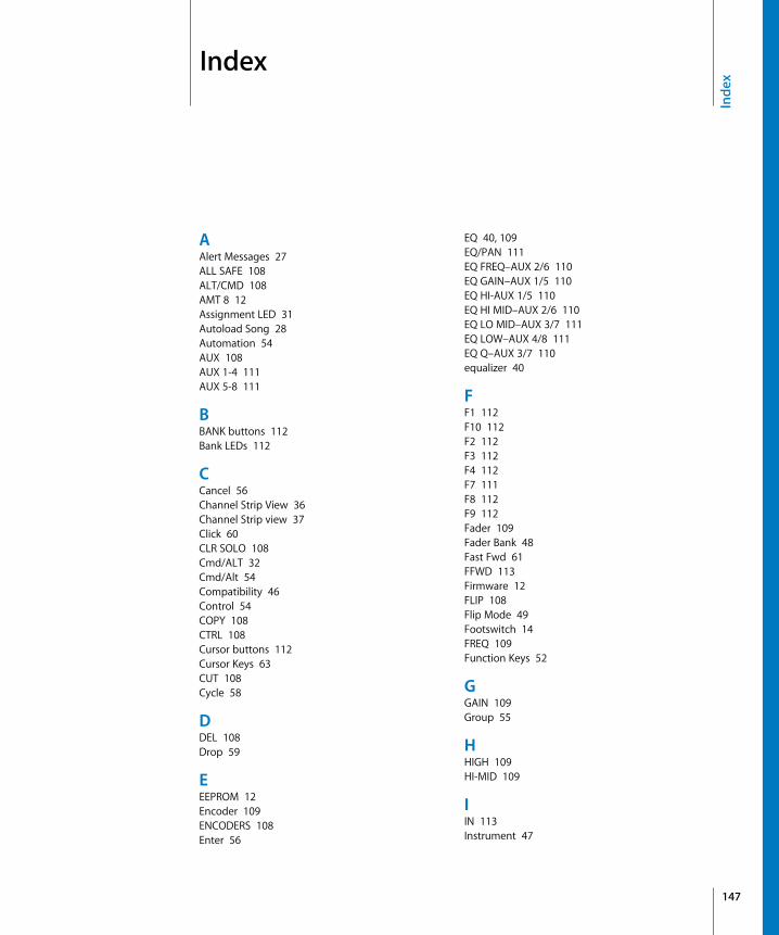
Inde
x
Index
AAlert Messages 27ALL SAFE 108ALT/CMD 108AMT 8 12Assignment LED 31Autoload Song 28Automation 54AUX 108AUX 1-4 111AUX 5-8 111
BBANK buttons 112Bank LEDs 112
CCancel 56Channel Strip View 36Channel Strip view 37Click 60CLR SOLO 108Cmd/ALT 32Cmd/Alt 54Compatibility 46Control 54COPY 108CTRL 108Cursor buttons 112Cursor Keys 63CUT 108Cycle 58
DDEL 108Drop 59
EEEPROM 12Encoder 109ENCODERS 108Enter 56
EQ 40, 109EQ/PAN 111EQ FREQ–AUX 2/6 110EQ GAIN–AUX 1/5 110EQ HI-AUX 1/5 110EQ HI MID–AUX 2/6 110EQ LO MID–AUX 3/7 111EQ LOW–AUX 4/8 111EQ Q–AUX 3/7 110equalizer 40
FF1 112F10 112F2 112F3 112F4 112F7 111F8 112F9 112Fader 109Fader Bank 48Fast Fwd 61FFWD 113Firmware 12FLIP 108Flip Mode 49Footswitch 14FREQ 109Function Keys 52
GGAIN 109Group 55
HHIGH 109HI-MID 109
IIN 113Instrument 47
147
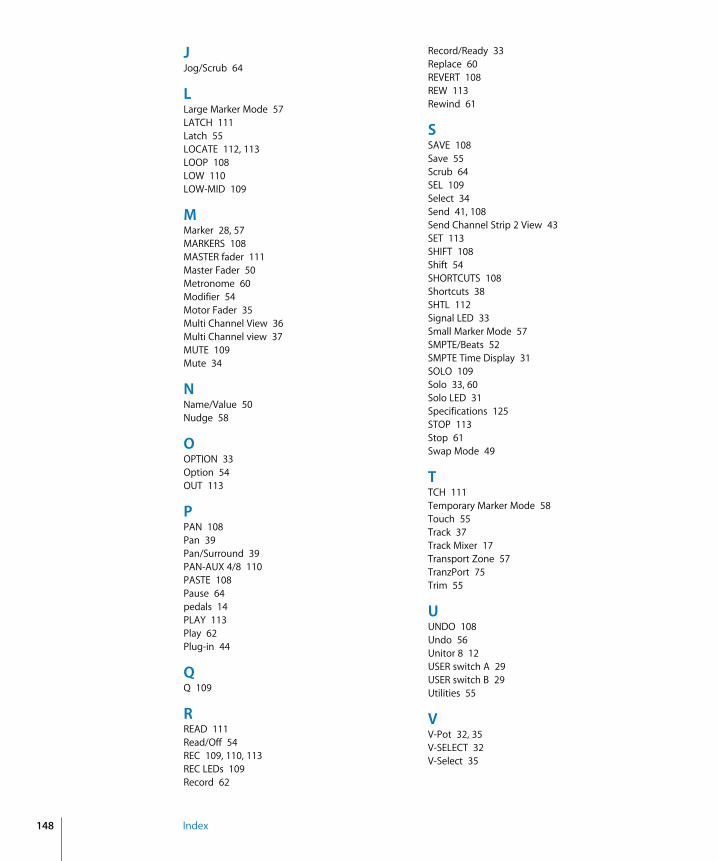
148
JJog/Scrub 64
LLarge Marker Mode 57LATCH 111Latch 55LOCATE 112, 113LOOP 108LOW 110LOW-MID 109
MMarker 28, 57MARKERS 108MASTER fader 111Master Fader 50Metronome 60Modifier 54Motor Fader 35Multi Channel View 36Multi Channel view 37MUTE 109Mute 34
NName/Value 50Nudge 58
OOPTION 33Option 54OUT 113
PPAN 108Pan 39Pan/Surround 39PAN-AUX 4/8 110PASTE 108Pause 64pedals 14PLAY 113Play 62Plug-in 44
QQ 109
RREAD 111Read/Off 54REC 109, 110, 113REC LEDs 109Record 62
Record/Ready 33Replace 60REVERT 108REW 113Rewind 61
SSAVE 108Save 55Scrub 64SEL 109Select 34Send 41, 108Send Channel Strip 2 View 43SET 113SHIFT 108Shift 54SHORTCUTS 108Shortcuts 38SHTL 112Signal LED 33Small Marker Mode 57SMPTE/Beats 52SMPTE Time Display 31SOLO 109Solo 33, 60Solo LED 31Specifications 125STOP 113Stop 61Swap Mode 49
TTCH 111Temporary Marker Mode 58Touch 55Track 37Track Mixer 17Transport Zone 57TranzPort 75Trim 55
UUNDO 108Undo 56Unitor 8 12USER switch A 29USER switch B 29Utilities 55
VV-Pot 32, 35V-SELECT 32V-Select 35
Index

WWheel 112WRITE 111Write 55
ZZero Mode 49Zoom Key 63
Index 149