logic functions: an elementary processing function in a
TRANSCRIPT
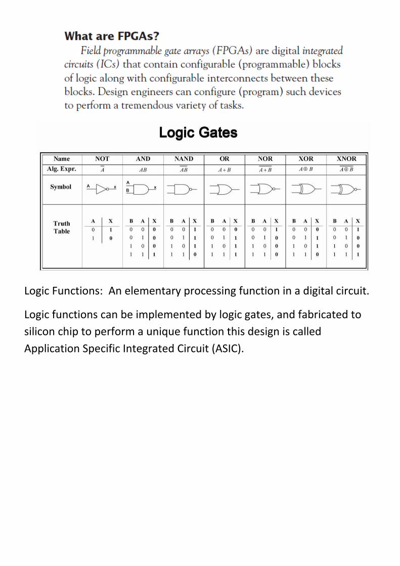
Logic Functions: An elementary processing function in a digital circuit.
Logic functions can be implemented by logic gates, and fabricated to
silicon chip to perform a unique function this design is called
Application Specific Integrated Circuit (ASIC).


Programmable Logic Devices
• Digital Electronic systems:
– Memory
– Microprocessor
– Logic Devices
• Fixed Function Logic Devices.
• Programmable Logic Devices.
1

Programmable Logic Devices
• Advantages Programmable Logic Devices:
– Less board space.
– Easy to change with rewiring.
– Faster.
– Less cost.
2

Programmable Logic Devices
• (PLDs) introduced in the mid 1970s.
• The idea: to construct logic circuits that were programmable.
• Microprocessors: can run a program but posses a fixed hardware.
• Programmability of PLDs was intended at the hardware level (reconfigured).
3

Programmable Logic Devices
• PAL (Programmable Array Logic) PLA (Programmable Logic Array)
• used only logic gates (no flip-flops), combinational circuits.
• registered PLDs: one flip-flop at each output; simple sequential functions.
• In the beginning of the 1980s, additional logic circuitry was added to each PLD output.
• Macrocell, contained (besides the flip-flop) logic gates and multiplexers.
4

Programmable Logic Devices
• Moreover, the cell itself was programmable, allowing several modes of operation.
• provided a ‘return’ (feedback) signal from the output of the circuit to the programmable array, which gave the PLD greater flexibility.
• This new PLD structure was called generic PAL (GAL).
• PALCE (PAL CMOS Electrically erasable/programmable).
5
Programmable Logic Devices
• (PAL, PLA, registered PLD, and GAL/PALCE) are now collectively referred to as SPLDs (Simple PLDs).
• Today GAL/PALCE device is the only still manufactured in a standalone package.
6

Programmable Logic Devices
• several GAL devices were fabricated on the same chip.
• This approach known as CPLD (Complex PLD).
• CPLDs are currently very popular due to:
• their high density,
• high performance,
• and low cost
• (CPLDs under a dollar can be found). 7

Programmable Logic Devices
• In the mid 1980s: FPGAs (Field Programmable Gate Arrays) were introduced.
• FPGAs differ from CPLDs in architecture, technology, built-in features, and cost.
• implementation of large size, high-performance circuits.
8

Programmable Logic Devices
PLDs
Simple PLD (SPLD)
PAL PLA Registered
PAL/PLA GAL
Complex PLD
(CPLD) FPGA
9

SPLDs (Simple PLDs): PAL Devices
• Introduced by Monolithic Memories in the mid 1970s.
• programmable array of AND gates, followed by a fixed array of OR gates.
• based on the fact that any combinational function can be represented by a Sum-of-Products (SOP).
10

SPLDs (Simple PLDs): PAL Devices
11

SPLDs (Simple PLDs): PAL Devices
• The main limitation: allowed only the implementation of combinational functions.
• registered PALs launched end of the 1970s.
• These included a flip-flop at each output (after the OR gates in figure A1), allowing the implementation of sequential functions.
12

SPLDs (Simple PLDs): PAL Devices PAL16L8
• An example : PAL16L8
• 16 inputs and 8 outputs
• only 18 I/O available, because it was a 20-pin DIP package
• 10 IN pins, 2 OUT pins, 6 IN/OUT pins, plus VCC and GND.
13

SPLDs (Simple PLDs): PAL Devices PAL16L8
• Its registered counterpart was the 16R8 chip (where R stands for Registered).
• fabrication technology :bipolar. • 5 V supply. • current consumption : 200 mA.
• maximum frequency : 100 MHz. • programmable cells: of PROM
(fuse links) or EPROM (20min UV erase time) type.
14

SPLDs (Simple PLDs): PLA Devices
• programmable array of AND gates, followed by a programmable array of OR gates.
• Advantage: was greater flexibility than PAL.
•
• However, higher time constants at the internal nodes lowered the circuit speed.
15

SPLDs (Simple PLDs): PLA Devices
16

SPLDs (Simple PLDs): PLA Devices
• example :Signetics PLS161 device.
• 12 inputs and 8 outputs,
• A total of 48 12-input AND gates, followed by a total of 8 48-input OR gates.
• At the outputs, additional programmable XOR gates were also available.
17

GAL Devices
• Generic PAL introduced by Lattice in 1980s.
• A more sophisticated output cell (Macrocell):
– Included besides the flip-flop, several gates and multiplexers.
– Macrocell itself was programmable.
– a ‘return’ signal from the output of the Macrocell to the programmable array.
• EEPROM was employed instead of PROM or EPROM.
1

GAL Devices
• GAL is the only SPLD (Simple PLD) still manufactured in a standalone package.
• serves as the basic building block in the construction of most CPLDs (there are exceptions, however, like the CoolRunner CPLD, which employs PLAs instead).
2

GAL Devices
3

Complex PLD (CPLD)
• several PLDs (in general of GAL type) fabricated on a single chip.
• With programmable switch matrix.
• JTAG support • interface to other logic
standards (1.8 V, 2.5 V, 5 V, etc.).
• Altera, Xilinx, Lattice, Atmel, Cypress, etc.
4

Complex PLD (CPLD)
• Applications:
– Decoders
– Encoders
– Multiplexers
– De-Multiplexers
5

Field Programmable Gate Array (FPGA)
• introduced by Xilinx in the mid 1980s.
• differ from CPLDs in architecture, storage technology, number of built-in features, and cost.
• Aimed at the implementation of high performance, large-size circuits.
6

7
Field Programmable Gate Array (FPGA)
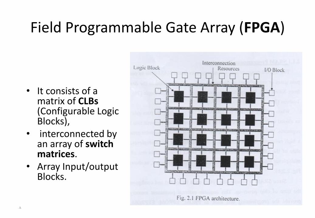
• It consists of a matrix of CLBs (Configurable Logic Blocks),
• interconnected by an array of switch matrices.
• Array Input/output Blocks.
8

Field Programmable Gate Array (FPGA)
• First, instead PAL (in SPLDs), its operation is normally based on a LUT (lookup table).
• The number of flip-flops is much more abundant (more sophisticated sequential Circuits).
• JTAG support. • interface to diverse logic levels. • SRAM memory • clock multiplication (PLL or DLL). • PCI interface, etc. • Some chips: multipliers, DSPs, and
microprocessors.
9

Field Programmable Gate Array (FPGA)
• Storage of the interconnects:
– CPLDs are non-volatile (antifuse, EEPROM, Flash, etc.).
– most FPGAs use SRAM, and are therefore volatile.
• saves space and lowers the cost but requires an external ROM.
– non-volatile FPGAs (with antifuse), which might be advantageous when reprogramming is not necessary.
10

Field Programmable Gate Array (FPGA)
• Several companies manufacture FPGAs, like Xilinx, Actel, Altera, QuickLogic, Atmel, etc.
• Interconnects: – all Xilinx FPGAs use SRAM, reprogrammable, but
volatile (thus requiring external ROM).
– Actel FPGAs use antifuse , non-volatile (they), but are non-reprogrammable (except one family, which uses Flash memory).
11

Field Programmable Gate Array (FPGA)
• the actual application will dictate which chip architecture is most appropriate.
• Applications: – Aerospace and Defense. – Medical Elctronics. – Wired Communications. – Wireless Communications. – High performance computing.
12

Performance vs. Flexibility
ECEn/CS 224 13 19 FPGA
Page 13
Flex
ibili
ty
Performance
ASICs
CPUs & DSPs
FPGAs
Goal: the performance of ASIC’s with the flexibility of programmable processors.
ASIC = Application Specific Integrated Circuit

14

جامعة نينوى
كلية هندسة الإلكترونيات
Circuit Design with VHDL
Submitted By: Hussein Aideen
Textbook: Volnei A. Pedroni

VHDL> Introduction
VHDL stands for VHSIC Hardware Description Language.
VHSIC is itself an abbreviation for Very High Speed Integrated
Circuits.
Describes the behavior of an electronic circuit or system, from
which the physical circuit or system can then be implemented.
first HDL standardized, IEEE 1076 standard.

VHDL> Introduction
Once the VHDL code has been written:
used either to implement the circuit in a programmable device
(from Altera, Xilinx, Atmel, etc.)
or can be submitted to a foundry for fabrication of an ASIC chip.
Currently, many complex commercial chips (microcontrollers,
for example) are designed using such an approach.
its statements are concurrent (parallel).

VHDL> Design Flow

VHDL> Design Flow

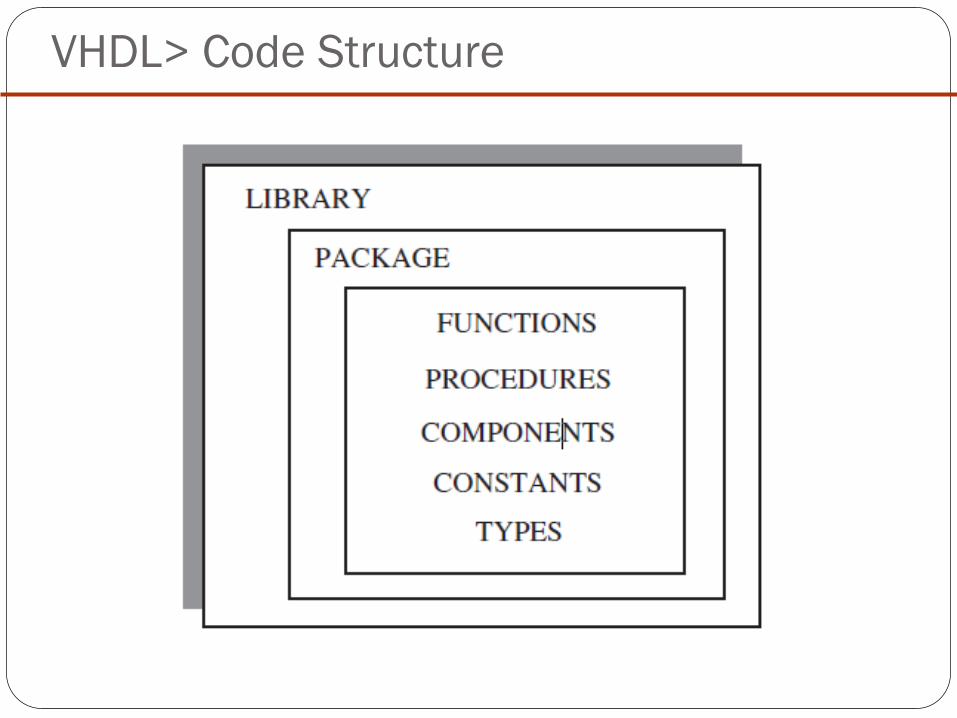
VHDL> Code Structure

VHDL> Code Structure
LIBRARY declarations:
A LIBRARY is a collection of commonly used pieces of code. Placing such
pieces inside a library allows them to be reused or shared by other designs.
VHDL> Code Structure

VHDL> Code Structure
An ENTITY is a list with specifications of all input and output pins
(PORTS) of the circuit. Its syntax is shown below.

VHDL> Code Structure
The mode of the signal can be:
IN, OUT, INOUT, or BUFFER.
IN and OUT are truly unidirectional pins,
INOUT is bidirectional.
BUFFER, output signal must read internally.
The type of the signal can be BIT, STD_LOGIC, INTEGER, etc. (discussed later).
Finally, the name any name, except VHDL reserved words
VHDL> Code Structure
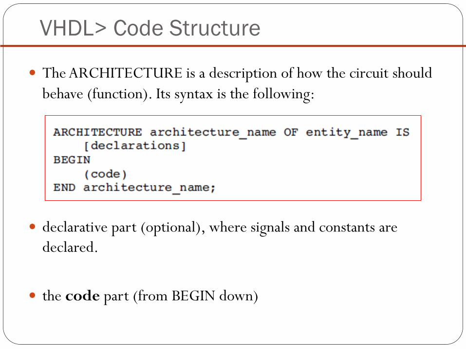
The ARCHITECTURE is a description of how the circuit should
behave (function). Its syntax is the following:
declarative part (optional), where signals and constants are
declared.
the code part (from BEGIN down)

VHDL> Introductory Examples
Process
VHDL is inherently concurrent (contrary to regular computer
programs, which are sequential),
so to implement any clocked circuit (flip-flops, for example) we
have to ‘‘force’’ VHDL to be sequential.

VHDL> Introductory Examples
DFF
Exam: Q1) Write a VHDL code to synthesis the following circuit
(DFF) shown in figure below:

VHDL> Introductory Examples
DFF

VHDL> Introductory Examples
DFF with Asynchronous Reset
Exam: Q1) Write a VHDL code to synthesis the following circuit
(DFF with Asynchronous Reset) shown in figure below:

VHDL> Introductory Examples

VHDL> J-k FF

VHDL> T FF

Circuit Design with VHDL 2
Hussein Aideen
جامعة نينوى
كلية هندسة الإلكترونيات

VHDL> Data Types
Pre-Defined Data Types:
◦ BIT (and BIT_VECTOR): 2-level logic (‘0’, ‘1’).

VHDL> Data Types

VHDL> Data Types
STD_LOGIC (and STD_LOGIC_VECTOR):
8-valued logic system introduced in the IEEE 1164 standard. ◦ ‘X’ Forcing Unknown (synthesizable unknown)
◦ ‘0’ Forcing Low (synthesizable logic ‘1’)
◦ ‘1’ Forcing High (synthesizable logic ‘0’)
◦ ‘Z’ High impedance (synthesizable tri-state buffer)
◦ ‘W’ Weak unknown
◦ ‘L’ Weak low
◦ ‘H’ Weak high
◦ ‘–’ Don’t care

VHDL> Data Types

VHDL> Data Types
BOOLEAN: True, False.
INTEGER: 32-bit integers (from -2,147,483,648 to +2,147,483,647).
NATURAL: Non-negative integers (from 0 to +2,147,483,647).
SIGNED and UNSIGNED: data types defined in the std_logic_arith package of the ieee library. They have the appearance of STD_LOGIC_VECTOR, but accept arithmetic operations, which are typical of INTEGER data types.
REAL: Real numbers ranging from -1.0E38 to +1.0E38. Not synthesizable.
Physical literals: Used to inform physical quantities, like time, voltage, etc. Useful in simulations. Not synthesizable.

VHDL> Data Types
Examples:

VHDL> Data Types
Examples:

VHDL> Data Types

Ex: Write VHDL code to design 8-3 encoder (use if statement)

VHDL> Data Types User-Defined Data Types:
VHDL also allows the user to define his/her own
data types.

VHDL> Data Types

VHDL> Data Types Sub-Types:
The main reason for using a subtype rather than specifying a new type is
that, though operations between data of different types are not allowed,
they are allowed between a subtype and its corresponding base type.

VHDL> Data Types
Signed and Unsigned Data Types:
◦ defined in the std_logic_arith package of the ieee library.

VHDL> Data Types


جامعة نينوى
كلية هندسة الإلكترونيات
Circuit Design with VHDL 3
Submitted By: Hussein Aideen
Textbook: Volnei A. Pedroni

VHDL> Data Conversion
VHDL does not allow direct operations between data of different
types.
it is necessary to convert data from one type to another.
If the data are closely related: std_logic_1164 of the ieee library
provides straightforward conversion functions.

VHDL> Data Conversion
Data conversion functions: std_logic_arith package of the ieee library.
Output data type Input data type keyword
INTEGER INTEGER, UNSIGNED,
SIGNED, or STD_ULOGIC
conv_integer(p)
UNSIGNED
* Where b is number of bits.
INTEGER, UNSIGNED,
SIGNED, or STD_ULOGIC
conv_unsigned(p, b)
SIGNED INTEGER, UNSIGNED,
SIGNED, or STD_ULOGIC
conv_signed(p, b):
STD_LOGIC_VECTOR INTEGER, UNSIGNED,
SIGNED, or STD_ULOGIC
conv_std_logic_vector(p, b)

VHDL> Data Conversion
Data conversion functions: std_logic_signed or std_logic_unsigned
package of the ieee library.
Output data type Input data type keyword
UNSIGNED STD_LOGIC_VECTOR
unsigned(p)
SIGNED STD_LOGIC_VECTOR
signed(p):
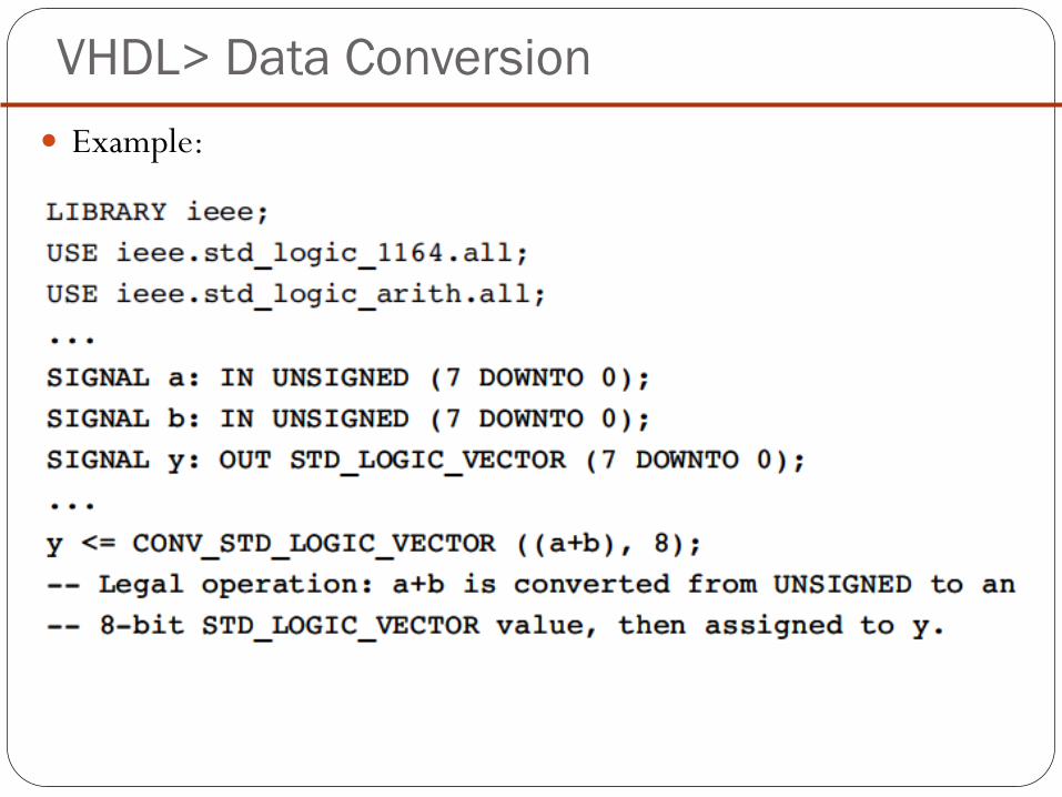
VHDL> Data Conversion
Example:

VHDL> Examples:
A 4-bit adder:

VHDL> Examples:
A 4-bit adder:

VHDL>Static and non-static data
CONSTANT: establish default values
can be declared in a PACKAGE, ENTITY, or ARCHITECTURE.

VHDL>Static and non-static data
GENERIC:
specifying a generic parameter (that is, a static parameter ).
code more flexibility and reusability.
must be declared in the ENTITY.

VHDL>Static and non-static data
SIGNAL:
pass values in and out the circuit, as well as between its internal
units.
circuit interconnects (wires).

VHDL>Static and non-static data
VARIABLE:
represents only local information.
It can only be used inside a sequential code (PROCESS for example).

VHDL>Static and non-static data

VHDL> Operators
VHDL provides several kinds of pre-defined operators:
Assignment operators
Logical operators
Arithmetic operators
Relational operators
Shift operators
Concatenation operators

VHDL> Operators
Assignment operators
using Operator
SIGNAL. <=
VARIABLE, CONSTANT, GENERIC, initial values.
:=
vector elements or with OTHERS.
=>

VHDL> Operators
Assignment operators

جامعة نينوى
كلية هندسة الإلكترونيات
Circuit Design with VHDL 4
Submitted By: Hussein Aideen
Textbook: Volnei A. Pedroni

VHDL> Operators
Logical operators: perform logical operations.
Data types: BIT, STD_LOGIC, STD_ULOGIC, BIT_VECTOR, STD_LOGIC_VECTOR, or STD_ULOGIC_VECTOR
NOT AND
OR
NAND
NOR
XOR
XNOR

VHDL> Operators
Arithmetic Operators:
perform arithmetic operations
data types: INTEGER, SIGNED, UNSIGNED, or REAL
With std_logic_signed or std_logic_unsigned package: STD_LOGIC_VECTOR.

VHDL> Operators
N bit adder circuit:

VHDL> Operators
N bit adder circuit:
VHDL> Operators
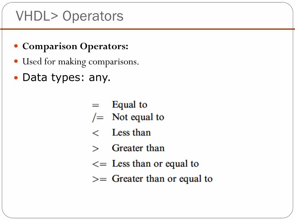
Comparison Operators:
Used for making comparisons.
Data types: any.

VHDL> Operators
N bit comparator:

VHDL> Operators

VHDL> Operators
Shift Operators:
Syntax:

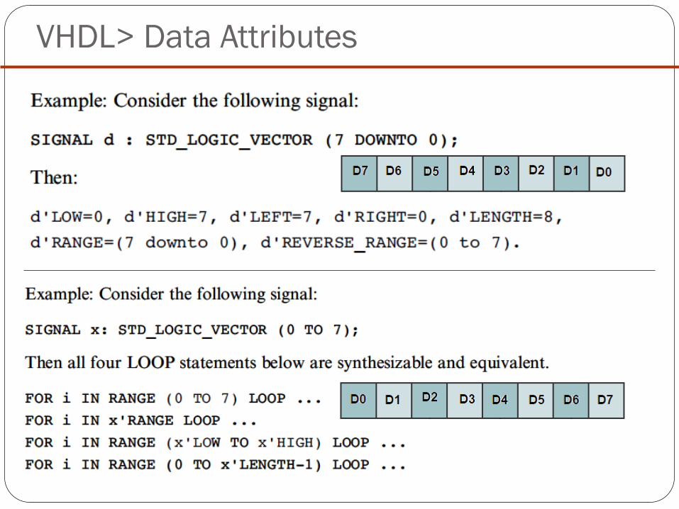
VHDL> Data Attributes
The pre-defined, synthesizable data attributes are the following:
d’LOW: Returns lower array index
d’HIGH: Returns upper array index
d’LEFT: Returns leftmost array index
d’RIGHT: Returns rightmost array index
d’LENGTH: Returns vector size
d’RANGE: Returns vector range
d’REVERSE_RANGE: Returns vector range in reverse order
VHDL> Data Attributes

VHDL> Signal Attributes
Let us consider a signal s. Then:
s’EVENT: Returns true when an event occurs on s.
s’STABLE: Returns true if no event has occurred on s.

VHDL> User-Defined Attributes
VHDL also allows the construction of user defined attributes.

جامعة نينوى
كلية هندسة الإلكترونيات
Circuit Design with VHDL 5
Submitted By: Hussein Aideen
Textbook: Volnei A. Pedroni

VHDL> Concurrent & sequential Code
Example: Write VHDL code to implement the following circuit.

VHDL> Concurrent & sequential Code
Concurrent Code:
WHEN,
GENERATE,
Assignments using only operators (AND, NOT, +, *, sll, etc.),
A special kind of assignment, called BLOCK.
Sequential Code:
PROCESSES, FUNCTIONS, PROCEDURES.
IF, WAIT, CASE, and LOOP.
VARIABLES.

VHDL>Combinational vs Sequential Logic
Combinational Logic: output depends solely on the current
inputs.
sequential logic: output depend on previous inputs.

VHDL> Concurrent versus Sequential
VHDL code is inherently concurrent (parallel).
Only statements placed inside a PROCESS, FUNCTION, or
PROCEDURE are sequential.
the block, as a whole, is concurrent with any other (external)
statements.
Concurrent code is also called dataflow code.
Concurrent: The order does not matter.
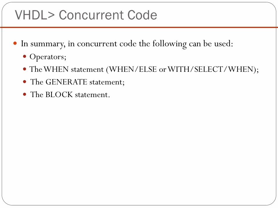
VHDL> Concurrent Code
In summary, in concurrent code the following can be used:
Operators;
The WHEN statement (WHEN/ELSE or WITH/SELECT/WHEN);
The GENERATE statement;
The BLOCK statement.

VHDL> Concurrent Code
Operators:

VHDL> Concurrent Code
Multiplexer #1

VHDL> Concurrent Code
WHEN (Simple and Selected)

VHDL> Concurrent Code
Whenever WITH / SELECT / WHEN is used:
all permutations must be tested,
keyword OTHERS is often useful.
keyword UNAFFECTED,
which should be used when no action is to take place.
‘‘WHEN value’’ can indeed take up three forms:

VHDL> Concurrent Code
Examples:

VHDL> Concurrent Code
Multiplexer #2: when/else

VHDL> Concurrent Code
Multiplexer #2: with/select/when

VHDL> Concurrent Code
Tri-state Buffer:

VHDL> Concurrent Code
Home Works: Encoder: page 73:

VHDL> Concurrent Code
Home Works: ALU: page 75

جامعة نينوى
كلية هندسة الإلكترونيات
Circuit Design with VHDL 6
Submitted By: Hussein Aideen
Textbook: Volnei A. Pedroni

VHDL> Concurrent Code
COMPONENT:
A COMPONENT is simply a piece of conventional code (that
is, LIBRARY declarations ENTITY ARCHITECTURE).
However, by declaring such code as being a COMPONENT,
it can then be used within another circuit, thus allowing the
construction of hierarchical designs.
A COMPONENT is also another way of partitioning a code and
providing code sharing and code reuse.
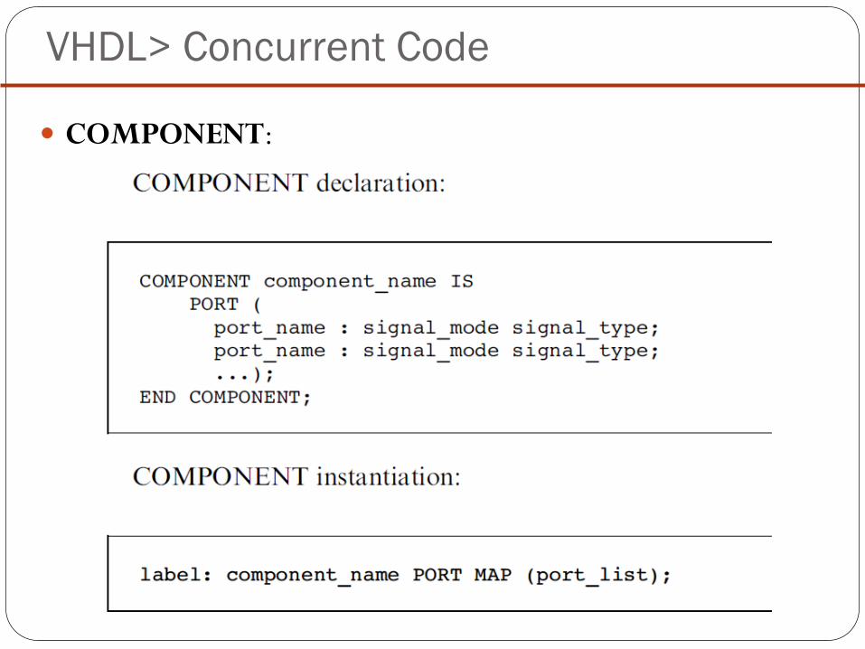
VHDL> Concurrent Code
COMPONENT:

VHDL> Concurrent Code
COMPONENT:
Example: invertor as component

VHDL> Concurrent Code
COMPONENT:
PORT MAP
There are two ways to map the PORTS of a COMPONENT
during its instantiation: positional mapping and nominal
mapping. Let us consider the following example:
VHDL> Concurrent Code
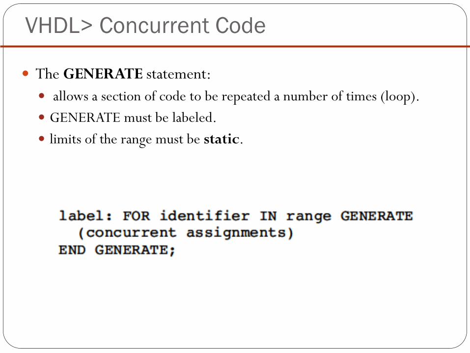
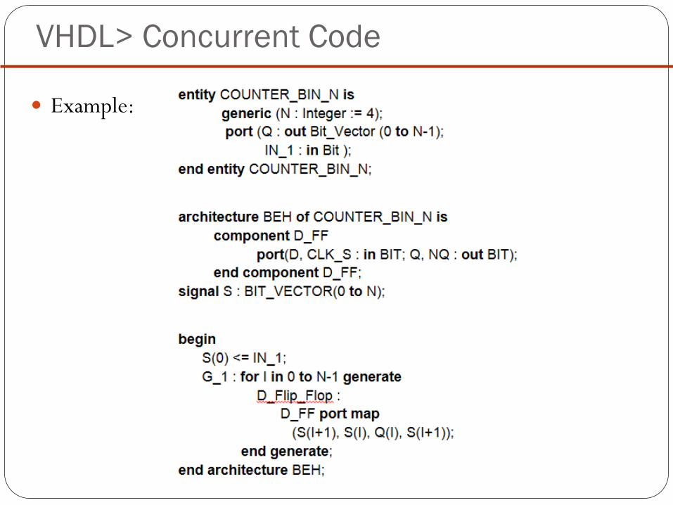
The GENERATE statement:
allows a section of code to be repeated a number of times (loop).
GENERATE must be labeled.
limits of the range must be static.

VHDL> Concurrent Code
IF/GENERATE: (ELSE is not allowed).
IF/GENERATE can be nested inside FOR/GENERATE, the
opposite can also be done.

VHDL> Concurrent Code
Example:

VHDL> Concurrent Code
Example: N-bit counter
VHDL> Concurrent Code
Example:

VHDL> Concurrent Code
BLOCK:
Simple BLOCK
locally partitioning the code.
turning the overall code more readable (long codes).
can be nested inside another BLOCK.

VHDL> Concurrent Code
Simple BLOCK:

VHDL> Concurrent Code
Simple BLOCK:

VHDL> Concurrent Code
Guarded BLOCK:
includes an additional expression, called guard
expression.
A guarded statement executed only when the guard
expression is TRUE.
sequential circuits can be constructed.

VHDL> Concurrent Code
DFF with Guarded BLOCK:

جامعة نينوى
كلية هندسة الإلكترونيات
Circuit Design with VHDL 7
Submitted By: Hussein Aideen
Textbook: Volnei A. Pedroni

VHDL> Sequential Code
PROCESSES, FUNCTIONS, and PROCEDURES are executed
sequentially.
any of these blocks is still concurrent with any other statements
placed outside it.
with it we can build sequential circuits as well as combinational
circuits.

VHDL> Sequential Code
IF, WAIT, CASE, and LOOP.
VARIABLES restricted to be used in sequential code.

VHDL> PROCESS
A PROCESS must be installed in the main code.
executed every time a signal in the sensitivity list changes.

VHDL> PROCESS
initial value is not synthesizable.
monitoring a signal (clock, for example) is necessary. A common
way of detecting a signal change is by means of the EVENT
attribute.
For instance, if clk is a signal to be monitored, then clk’EVENT
returns TRUE when a change on clk occurs (rising or falling
edge).

VHDL> PROCESS
IF statement:

VHDL> IF statement
One-digit Counter #1
1-digit decimal counter (0 9 0).

VHDL> IF statement
One-digit Counter #1
1-digit decimal counter (0 9 0).
VHDL> IF statement
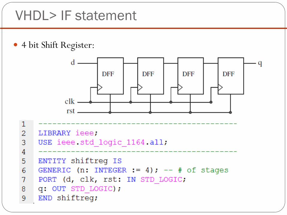
4 bit Shift Register:

VHDL> IF statement
4 bit Shift Register:

VHDL> WAIT statement
WAIT statement: (inside Process)
the PROCESS cannot have a sensitivity list when WAIT is
employed.

VHDL> WAIT statement
WAIT statement:
the PROCESS cannot have a sensitivity list when WAIT is
employed.

VHDL> WAIT statement
WAIT ON:
WAIT FOR is intended for simulation only (waveform generation for test-benches). Example: WAIT FOR 5ns;

VHDL> WAIT statement
Home Works:
DFF with Asynchronous Reset #2, Page 99.
One-digit Counter #2, Page 99-100.

VHDL> CASE statement
CASE statement:

VHDL> CASE statement
CASE statement:
CASE statement (sequential) is very similar to WHEN
(combinational)
keyword OTHERS is often helpful.
Another important keyword is NULL (the counterpart of
UNAFFECTED), which should be used when no action is to take
place.
CASE allows multiple assignments for each test condition.

VHDL> CASE statement
Two-digit Counter with SSD Output:

VHDL> Two-digit Counter with SSD
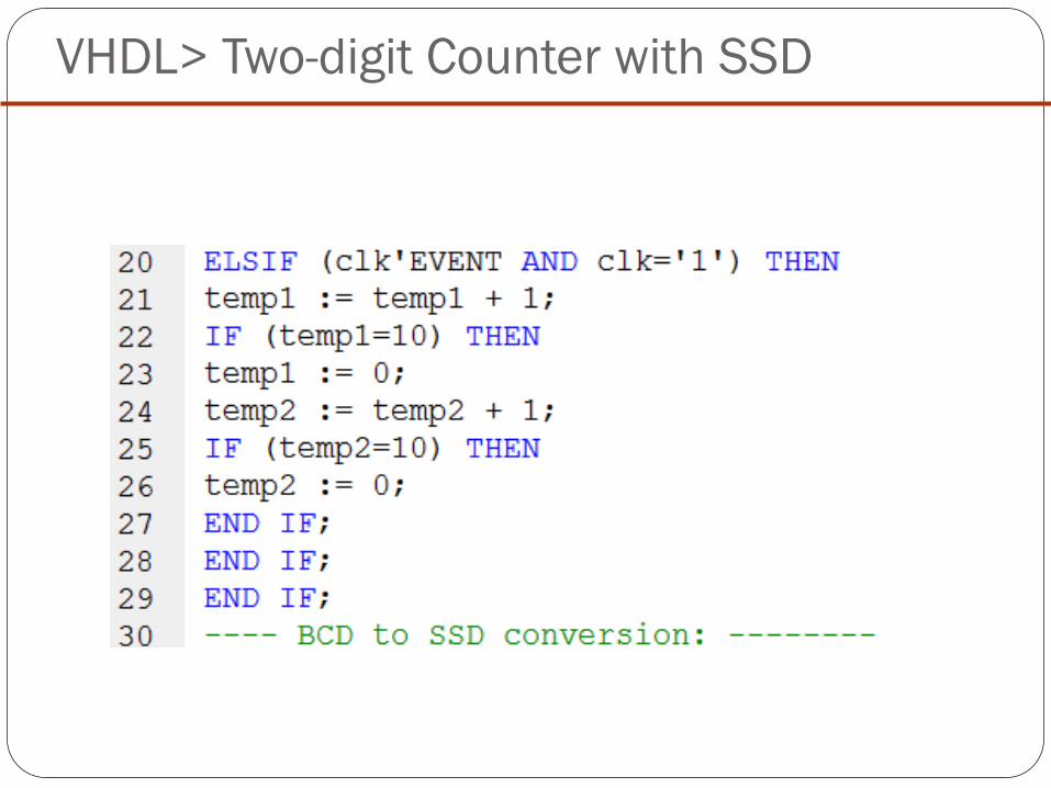
VHDL> Two-digit Counter with SSD

VHDL> Two-digit Counter with SSD

VHDL> Two-digit Counter with SSD

VHDL> Examples
Generic Decoder:
If ena = ‘0’, then all bits of x should be high; otherwise, the output bit
selected by sel should be low.

VHDL> Examples
Generic Decoder:

VHDL> Examples
Gray code counter:

جامعة نينوى
كلية هندسة الإلكترونيات
Circuit Design with VHDL 8
Submitted By: Hussein Aideen
Textbook: Volnei A. Pedroni

VHDL> Loop statement
LOOP is useful when a piece of code must be instantiated several
times.
inside a PROCESS, FUNCTION, or PROCEDURE.
FOR / LOOP: repeated a fixed number of times.
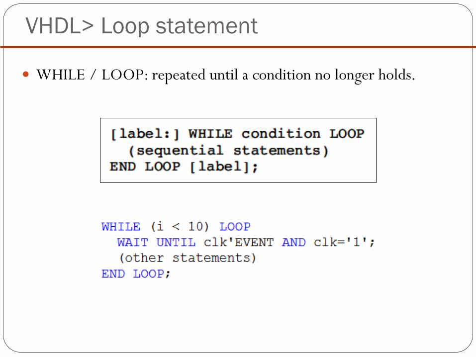
VHDL> Loop statement
WHILE / LOOP: repeated until a condition no longer holds.

VHDL> Loop statement
EXIT: Used for ending the loop.
NEXT: Used for skipping loop steps.

VHDL> Loop statement
Simple Barrel Shifter:
The circuit must shift the input vector (of size 8) either 0 or 1
position to the left. When actually shifted (shift = 1), the LSB bit
must be filled with ‘0’ (shown in the botton left corner of the
diagram).
If shift = 0, then outp = inp;
if shift = 1, then outp(0) = ‘0’ and outp(i) = inp(i - 1), for 1≤ i
≤7.

VHDL> Loop statement
If shift = 0, then outp = inp;
if shift = 1, then outp(0) = ‘0’ and
outp(i) = inp(i - 1), for 1≤ i ≤7.

VHDL> Simple Barrel Shifter

VHDL> Simple Barrel Shifter

VHDL> Examples
Generic Parity Generator:
The circuit must add one bit to the input vector (on its left).
Such bit must be a ‘0’ if the number of ‘1’s in the input vector is even,
or a ‘1’ if it is odd, such that the resulting vector will always contain an
even number of ‘1’s (even parity).

VHDL> Examples
Generic Parity Generator:
1
0
1
1
0
1
1
1
Temp2
Output
1
0
1
1
0
1
1
1 temp1
input
6
0
0-1-0-0-1-0-0-1

VHDL> Examples
Generic Parity Detector:
The circuit must provide output = ‘0’ when the number of ‘1’s in
the input vector is odd, or output = ‘1’ otherwise.

VHDL> Examples
Generic Parity Detector:
1
0
1
0
0
1
1
0
0
1 XOR
temp input
0-1-1-0-0-0-1-0-0 1
output
not
temp

جامعة نينوى
كلية هندسة الإلكترونيات
Circuit Design with VHDL 9
Submitted By: Hussein Aideen
Textbook: Volnei A. Pedroni

VHDL> Arrays in VHDL
Arrays are collections of objects of the same type.
one-dimensional (1D),
two-dimensional (2D),
one-dimensional-by-one-
dimensional (1Dx1D).

VHDL> Arrays in VHDL
First the new TYPE must be defined,
Then the new SIGNAL, VARIABLE, or CONSTANT
can be declared using that data type.
TYPE type_name IS ARRAY (specification) OF data_type;
SIGNAL signal_name: type_name [:= initial_value];

VHDL> Arrays in VHDL
Initial value:
2D Array

VHDL> Arrays in VHDL
Arrays assignments

ROM (Read Only Memory)
Example: Write a VHDL code to design a ROM which has a size of 64bit i.e. word size=8, number of addresses =8, assume a random data are stored in the memory.

ROM (Read Only Memory)

جامعة نينوى
كلية هندسة الإلكترونيات
Circuit Design with VHDL 10
Submitted By: Hussein Aideen
Textbook: Volnei A. Pedroni

VHDL> Examples
Signed and Unsigned Comparators
VHDL> Examples
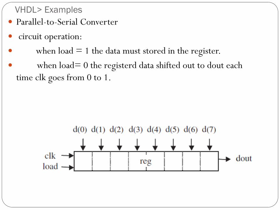
Parallel-to-Serial Converter
circuit operation:
when load = 1 the data must stored in the register.
when load= 0 the registerd data shifted out to dout each
time clk goes from 0 to 1.

VHDL> Examples
Parallel-to-Serial Converter

VHDL> Examples
Parallel-to-Serial Converter

VHDL> Examples
Signal Generators

VHDL> Examples
Signal Generators

VHDL> Examples
Signal Generators

جامعة نينوى
كلية هندسة الإلكترونيات
Circuit Design with VHDL 11
Submitted By: Hussein Aideen
Textbook: Volnei A. Pedroni

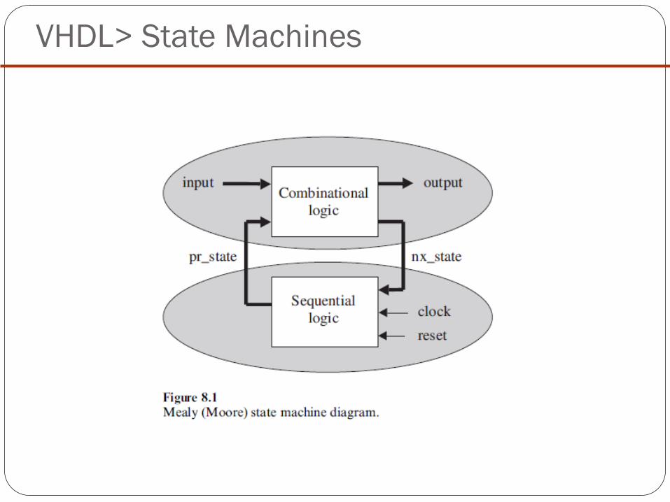
VHDL> State Machines
Finite state machines (FSM) constitute a special modeling
technique for sequential logic circuits.
helpful in the design of certain types of systems, (digital
controllers, counters, for example).

VHDL> State Machines
Mealy machine: the output of the machine depends not only on
the present state but also on the current input.
Moore machine: the output depends only on the current state.
VHDL> State Machines

VHDL> State Machines
Design Style #1:
the design of the lower section is completely separated from that
of the upper section.

VHDL> State Machines
Design of the Lower (Sequential) Section:

VHDL> State Machines
Design of the Upper (Combinational) Section:

VHDL> State Machines
Example

VHDL> State Machines

VHDL> State Machines

VHDL> State Machines
Design Style #2 (Stored Output):
In #1: Notice that in this case, if it is a Mealy machine (one whose
output is dependent on the current input), the output might
change when the input changes (asynchronous output).
To make Mealy machines synchronous.

VHDL> State Machines
Design Style #2 (Stored Output):

VHDL> State Machines
Design Style #2 (Stored Output):