logical db design 5. 1 cse2132 database systems week 5 lecture logical database design
TRANSCRIPT

Logical DB Design 5. 1
CSE2132 Database Systems
Week 5 Lecture
Logical Database Design

Logical DB Design 5. 2
Logical DB Design in the System LifecycleProject Identificationand Selection
Project Initiationand Planning
Logical design
Analysis
Physical design
Implementation
Maintenance
Conceptual Data Modeling
Enterprise Modeling
Logical Database Design
Physical Database Design
Database Implementation
}
DB Maintenance

Logical DB Design 5. 3
Logical Database Design
Performed by Data Analysts and Database Administrators
Steps
1. Conceptual Model (ER Diagram) mapped onto a logical model dependent on the DBMS characteristics. (The group of slides following numbered 1 to 8)
2. De-normalization (Optimize for efficiency). (The remaining slides in the lecture)
Logical DB Design 5. 4
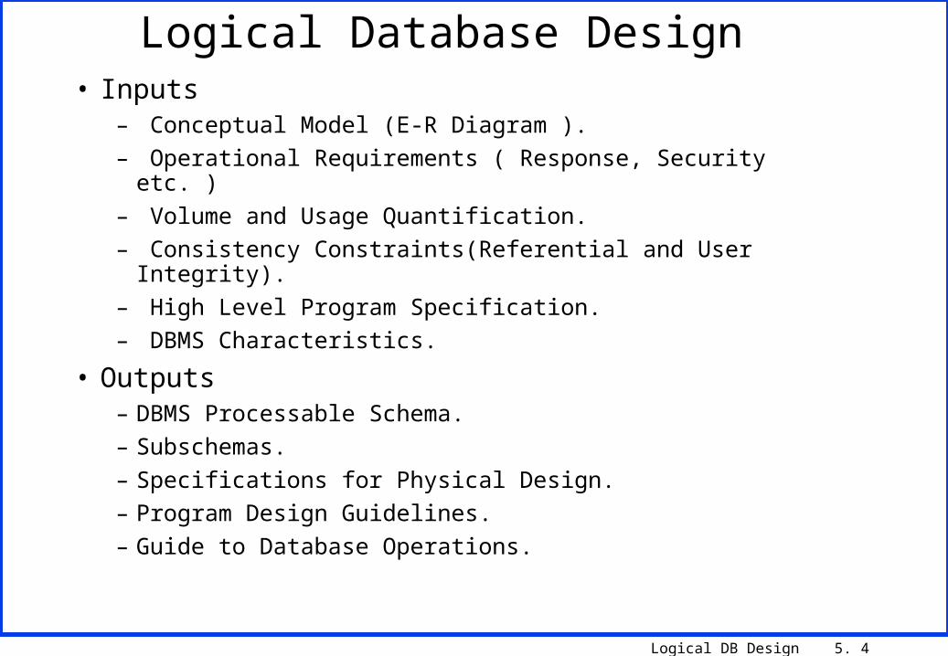
Logical Database Design• Inputs
– Conceptual Model (E-R Diagram ).
– Operational Requirements ( Response, Security etc. )
– Volume and Usage Quantification.
– Consistency Constraints(Referential and User Integrity).
– High Level Program Specification.
– DBMS Characteristics.
• Outputs– DBMS Processable Schema.
– Subschemas.
– Specifications for Physical Design.
– Program Design Guidelines.
– Guide to Database Operations.

Logical DB Design 5. 5
E-R Diagram to Relational Model
*Convert the ER Diagram to Tables
* Transform the Attributes in the ER Diagram to columns
* Identify the Primary Keys
* Identify the Referential Constraints
Overview

Logical DB Design 5. 6
EMPLOYEEDEPARTMENT
PROJECTSUPERVISION
DEPENDENT
DEPENDENTS_OF
WORKS_ON
MANAGES
WORKS_FOR
CONTROLS
N 1
11
1 N 1
N
NM
Fname Lname
NameSex
AddressSalary
Snn
Bdate
StartDate
NameNumber
Locations
Hours
NameNumber
Location
Name Sex Birthdate
1
N
E/R Diagram
Logical DB Design 5. 7
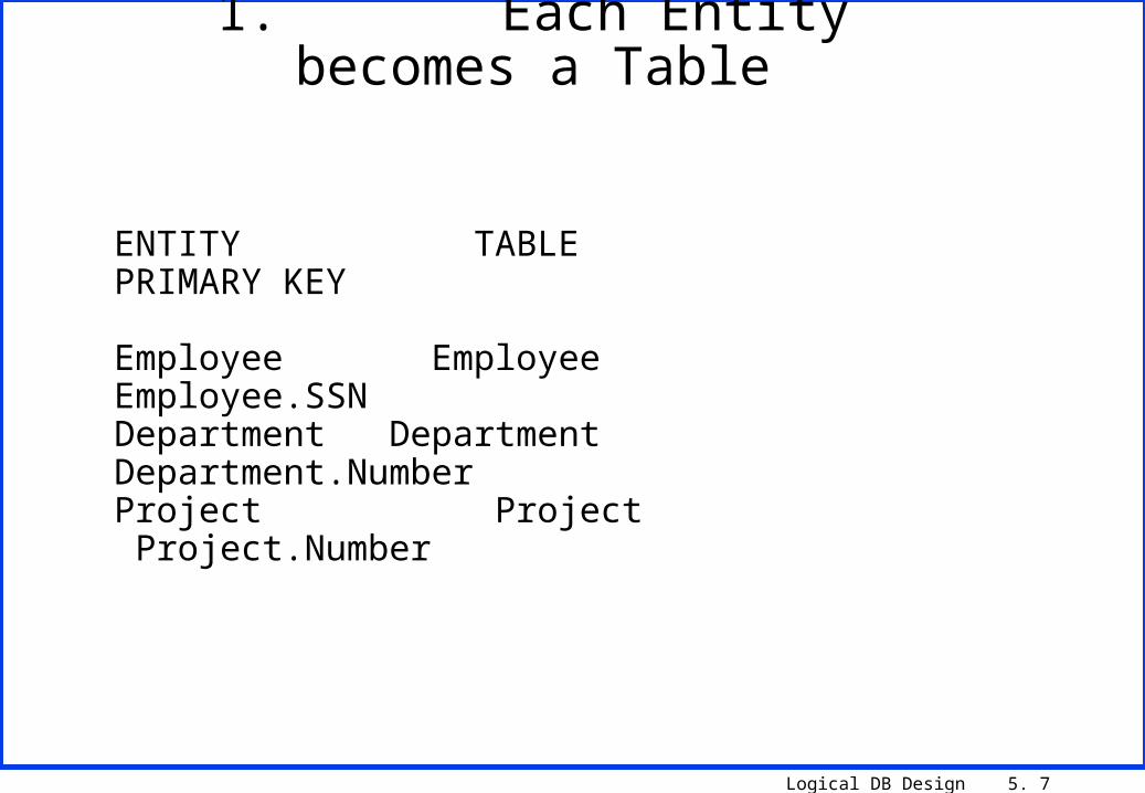
ENTITY TABLE PRIMARY KEY
Employee Employee Employee.SSNDepartment Department Department.NumberProject Project Project.Number
1. Each Entity becomes a Table

Logical DB Design 5. 8
For each weak entity create a table- include the Primary Key attribute of the owner tables The Primary Key becomes the :-
. owner key plus the weak entity key
Entity Table Primary Key
Dependent Dependent Employee.SSN + Dependent.Name
2. Weak Entities become Tables

Logical DB Design 5. 9
For each binary 1:1 relationship choose the entity withtotal participation and include the relationship attributes in that entity
EMPLOYEE MANAGES DEPARTMENT
- departments must always have a manager- employees are not always managers
Department has mandatory participation in the relationship.
- include the attributes of MANAGES (Start Date) and the primary key of EMPLOYEE (SSN) in the DEPARTMENT entity ( named so as to indicate role Mgrssn )
3. One to One Relationships
Logical DB Design 5. 10
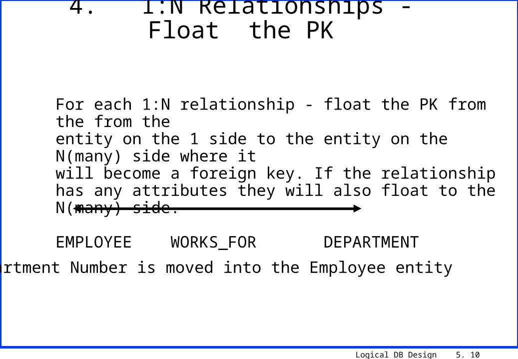
For each 1:N relationship - float the PK from the from theentity on the 1 side to the entity on the N(many) side where itwill become a foreign key. If the relationship has any attributes they will also float to the N(many) side.
EMPLOYEE WORKS_FOR DEPARTMENT
N 1
Department Number is moved into the Employee entity
4. 1:N Relationships - Float the PK

Logical DB Design 5. 11
For each M:N relationship create a new table with the Primary key being the the PK of both entities involvedin the relationship plus any attributes of the relationship.
EMPLOYEE WORKS_ON PROJECT E# HOURS P#
E1 P1 3E1 P2 4E2 P1 5E3 P2 3
5. M:N Relationships
Logical DB Design 5. 12
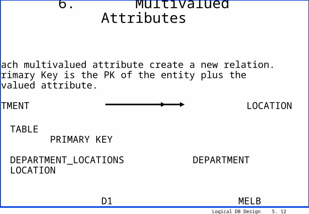
For each multivalued attribute create a new relation.The Primary Key is the PK of the entity plus the multivalued attribute.
DEPARTMENT LOCATION
TABLE PRIMARY KEY
DEPARTMENT_LOCATIONS DEPARTMENT LOCATION
D1 MELB D1 SYD D2 MELB
6. Multivalued Attributes

Logical DB Design 5. 13
For N-ary ( more than binary) Relationships create a new entity and float the Primary Key of each entity involved inthe relationship to the new entity.
Supplier supplies Parts from Cities
TABLES PRIMARY KEY
SUPPLIER_PARTS_CITIES S# P# C# S1 NUT MELB S1 NUT SYD
7. N-ary Relationships

Logical DB Design 5. 14
Fname Lname SSN Bdate Address Dno Salary Superssn Sex
Dname Dnumber Mgrssn Mgrstartdate
Dnumber Dlocation
Essn Pno Hours
Pname Pnumber Plocation Dno
Essn Dependent_name Sex Bdate
EMPLOYEE (100)
DEPARTMENT(10)
DEPT_LOCATIONS (15)
WORKS_ON(500)PROJECT (20)
DEPENDENT (200)
p.k
f.k
p.k
f.k f.k
f.k
NOTNULL
NOTNULL
f.kf.k
f.k
f.k
8. Include Volumes for each Tablein the Data Structure Diagram
Logical DB Design 5. 15
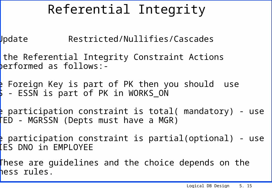
Delete/Update Restricted/Nullifies/Cascades
Setting the Referential Integrity Constraint Actionscan be performed as follows:-
. if the Foreign Key is part of PK then you should useCASCADES - ESSN is part of PK in WORKS_ON
. if the participation constraint is total( mandatory) - use RESTRICTED - MGRSSN (Depts must have a MGR)
. if the participation constraint is partial(optional) - use NULLIFIES DNO in EMPLOYEE
Nb: These are guidelines and the choice depends on thebusiness rules.
Referential Integrity

Logical DB Design 5. 16
Optimisation - maximise/minimise a strength/weakness of a resource
Therefore, we must know the characteristics of resources - cost/performance
List expensive resourcesList cheap resources
Optimize the Logical Model
Logical DB Design 5. 17
Application Development Time
Execution Time of Transactions
Data Storage Size
Flexibility to Changing requirements
. trade-off between the above depending on the priorities of the user (User Level Agreement)
Measure Success Optimization Against

Logical DB Design 5. 18
- Time to develop a system is kept to a minimum if the design is simple - ensuring no complex relationships - no tricks
- must have staff who are familiar with products anduse Rapid Application Development techniques
Optimisation of Development Time
Logical DB Design 5. 19
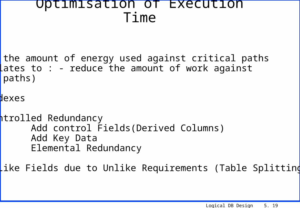
Reduce the amount of energy used against critical paths(Translates to : - reduce the amount of work againstaccess paths)
Use Indexes
Use Controlled Redundancy Add control Fields(Derived Columns) Add Key Data Elemental Redundancy
Split Like Fields due to Unlike Requirements (Table Splitting)
Optimisation of Execution Time

Logical DB Design 5. 20
CUSTOMER
ORDER
Tradeoff against flexibility - waste space, extra maintenance,more programming, more program work
> 20% redundancy - design problems
CUSTOMER
C#, CName, CAddress, CStatus
ORDER
O#, C#, OTotal, ODate
Redundancy - General Comments
Logical DB Design 5. 21
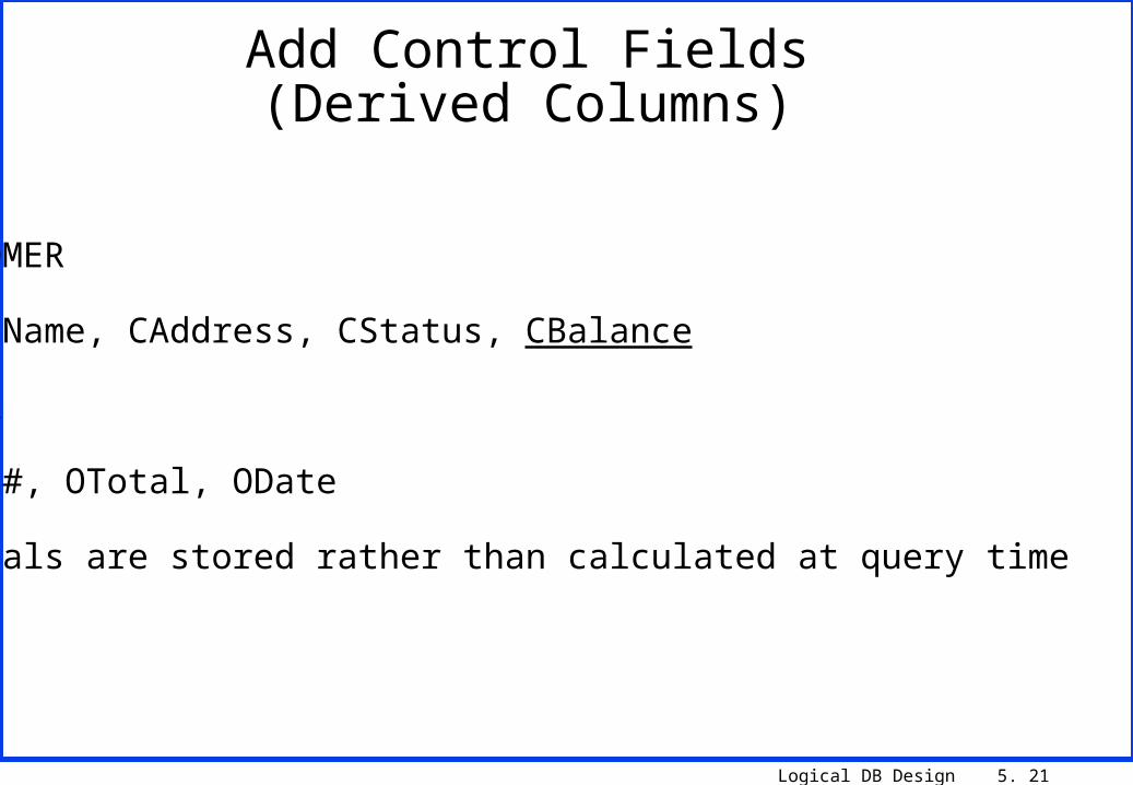
CUSTOMER
C#, CName, CAddress, CStatus, CBalance
ORDER
O#, C#, OTotal, ODate
- totals are stored rather than calculated at query time
Add Control Fields(Derived Columns)
Logical DB Design 5. 22
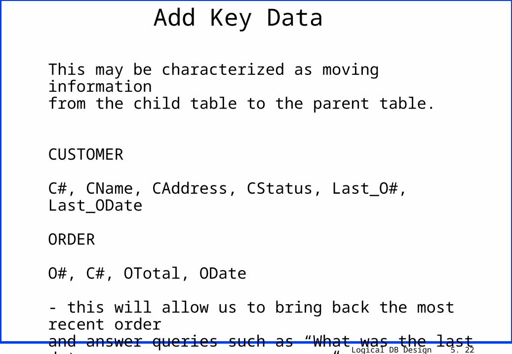
This may be characterized as moving information from the child table to the parent table.
CUSTOMER
C#, CName, CAddress, CStatus, Last_O#, Last_ODate
ORDER
O#, C#, OTotal, ODate
- this will allow us to bring back the most recent orderand answer queries such as “What was the last date Customer Smith made an order?”
Add Key Data

Logical DB Design 5. 23
This may be characterized as moving information from the parent table to the child table.
CUSTOMER
C#, CName, CAddress, CStatus
ORDER
O#, C#, OTotal, ODate, Caddress
- when we go to print out the Invoice we will not need togo to the Customer file to get the address
Elemental Redundancy

Logical DB Design 5. 24
The table is split into two tables. The attributes (or fields) have quite different usage patterns.
CUSTOMER
C#, CName, CAddress
CUSTOMER BATCH
C#, CStatus
- the status is only used by the batch program “update status”. So removing it makes the record smaller thus more records fit on a page of memory and less physical I/O is required to process each of the files.
Vertically Partition a Table

Logical DB Design 5. 25
Usually optimizing for efficiency is more important than optimizing for storage.
EMP(E# C7, EAddress C60, EQualification C40) - 107 bytes
1000 emp x 107 bytes = 107000 bytes
Using a CODE TABLE
EMP(E# C7, EAddress C60, EQual_Code C3) - 70 bytes
1000 x 70 = 70000 bytes
QUAL(Qual_Code C3, Qual_Desc 40) 43 x 500 = 21500 bytes
Creation of a Table to Optimize Storage

Logical DB Design 5. 26
Optimization of FlexibilityDo not de-normalize (ie. do not introduce redundancy).
Choose a data model which maximises data
independence.
Create an elastic data structure i.e. one which
is responsive to changing requirements
e.g. rather than hardcode values in a program
place the codes in a database.

Logical DB Design 5. 27
Physical Design• Stored Record Design
• Choice of File Organization
• Indexes and Clustering
• Choice of Compression
• File Placement