logicore ip axi master lite v3 - xilinx - all programmable · design tools: release notes guide....
TRANSCRIPT
LogiCORE IP AXI Master Lite v3.0
Product Guide for Vivado Design Suite
PG161 December 18, 2013
LogiCORE IP AXI Master Lite v3.0 www.xilinx.com 1PG161 December 18, 2013
Table of Contents
IP Facts
Chapter 1: Overview
Feature Summary. . . . . . . . . . . . . . . . . . . . . . . . . . . . . . . . . . . . . . . . . . . . . . . . . . . . . . . . . . . . . . . . . . 4
Applications . . . . . . . . . . . . . . . . . . . . . . . . . . . . . . . . . . . . . . . . . . . . . . . . . . . . . . . . . . . . . . . . . . . . . . 4
Unsupported Features. . . . . . . . . . . . . . . . . . . . . . . . . . . . . . . . . . . . . . . . . . . . . . . . . . . . . . . . . . . . . . 4
Licensing and Ordering Information . . . . . . . . . . . . . . . . . . . . . . . . . . . . . . . . . . . . . . . . . . . . . . . . . . . 5
Chapter 2: Product Specification
Standards . . . . . . . . . . . . . . . . . . . . . . . . . . . . . . . . . . . . . . . . . . . . . . . . . . . . . . . . . . . . . . . . . . . . . . . . 7
Performance. . . . . . . . . . . . . . . . . . . . . . . . . . . . . . . . . . . . . . . . . . . . . . . . . . . . . . . . . . . . . . . . . . . . . . 7
Resource Utilization. . . . . . . . . . . . . . . . . . . . . . . . . . . . . . . . . . . . . . . . . . . . . . . . . . . . . . . . . . . . . . . . 8
Port Descriptions . . . . . . . . . . . . . . . . . . . . . . . . . . . . . . . . . . . . . . . . . . . . . . . . . . . . . . . . . . . . . . . . . . 9
Chapter 3: Designing with the Core
General Design Guidelines . . . . . . . . . . . . . . . . . . . . . . . . . . . . . . . . . . . . . . . . . . . . . . . . . . . . . . . . . 13
Clocking. . . . . . . . . . . . . . . . . . . . . . . . . . . . . . . . . . . . . . . . . . . . . . . . . . . . . . . . . . . . . . . . . . . . . . . . . 14
Resets . . . . . . . . . . . . . . . . . . . . . . . . . . . . . . . . . . . . . . . . . . . . . . . . . . . . . . . . . . . . . . . . . . . . . . . . . . 14
Protocol Description . . . . . . . . . . . . . . . . . . . . . . . . . . . . . . . . . . . . . . . . . . . . . . . . . . . . . . . . . . . . . . 15
Send Feedback
LogiCORE IP AXI Master Lite v3.0 www.xilinx.com 2PG161 December 18, 2013
Chapter 4: Customizing and Generating the Core
Chapter 5: Constraining the Core
Chapter 6: Simulation
Chapter 7: Synthesis and Implementation
Chapter 8: Example Design
Chapter 9: Test Bench
Appendix A: Debugging
Finding Help on Xilinx.com . . . . . . . . . . . . . . . . . . . . . . . . . . . . . . . . . . . . . . . . . . . . . . . . . . . . . . . . . 26
Debug Tools . . . . . . . . . . . . . . . . . . . . . . . . . . . . . . . . . . . . . . . . . . . . . . . . . . . . . . . . . . . . . . . . . . . . . 27
Interface Debug . . . . . . . . . . . . . . . . . . . . . . . . . . . . . . . . . . . . . . . . . . . . . . . . . . . . . . . . . . . . . . . . . . 28
Appendix B: Additional Resources
Xilinx Resources . . . . . . . . . . . . . . . . . . . . . . . . . . . . . . . . . . . . . . . . . . . . . . . . . . . . . . . . . . . . . . . . . . 29
References . . . . . . . . . . . . . . . . . . . . . . . . . . . . . . . . . . . . . . . . . . . . . . . . . . . . . . . . . . . . . . . . . . . . . . 29
Revision History . . . . . . . . . . . . . . . . . . . . . . . . . . . . . . . . . . . . . . . . . . . . . . . . . . . . . . . . . . . . . . . . . . 30
Notice of Disclaimer. . . . . . . . . . . . . . . . . . . . . . . . . . . . . . . . . . . . . . . . . . . . . . . . . . . . . . . . . . . . . . . 30
Send Feedback

LogiCORE IP AXI Master Lite www.xilinx.com 3PG161 December 18, 2013 Product Specification
Introduction
The AXI Master Lite is an AXI4-compatible LogiCORE™ IP product. It provides an interface between a user-created IP core and an AXI4-Lite interface. The AXI4-Lite Master IP supports AXI4-Lite compatible bus mastering operations which are single 32-bit wide read or write data transfers.
Features
• AXI4-Lite Master interface
• Fixed 32-bit data width
• Supports single beat read and write data transfers of up to 4 bytes (32 bits)
IP Facts
LogiCORE IP Facts Table
Core Specifics
Supported Device Family(1) Zynq®-7000, 7 Series, UltraScale™ Architecture
Supported User Interfaces AXI4-Lite
Resources See Table 2-2.
Provided with Core
Design Files VHDL
Example Design Not Applicable
Test Bench Not Applicable
Constraints File Not Applicable
Simulation Model Not Applicable
Supported S/W Driver No drivers are available for this core.
Tested Design Flows(2)
Design Entry Vivado® Design Suite
Simulation For supported simulators, see the XilinxDesign Tools: Release Notes Guide.
Synthesis Vivado Synthesis
Support
Provided by Xilinx @ www.xilinx.com/support
Notes: 1. For a complete list of supported devices, see Vivado IP
catalog.2. For the supported versions of the tools, see the Xilinx Design
Tools: Release Notes Guide.
Send Feedback
LogiCORE IP AXI Master Lite v3.0 www.xilinx.com 4PG161 December 18, 2013
Chapter 1: Overview
Chapter 1
OverviewThe LogiCORE™ IP AXI Master Lite core provides an interface between a user-created IP core and an AXI4-Lite interface. The AXI4-Lite Master IP supports AXI4-Lite compatible bus mastering operations, which are single 32-bit wide read or write data transfers.
Feature Summary• AXI4-Lite Master interface
• Fixed 32-bit data width
• Supports single beat read and write data transfers of up to 4 bytes (32 bits)
ApplicationsThe AXI Master Lite core provides a AXI4-Lite mastering capability that has the legacy IP Interconnect (IPIC) User interface suitable for updating to AXI4 those legacy plbv46 designs that used the plbv46_master_single module.
The backend IPIC interface connects directly to the legacy User IPIC interface of the plbv46_master_single without modification. However, the plbv46 signal set has been replaced with AXI4-Lite master signal set. To migrate from a plbv46_master_single core:
• HDL changes:
° Modify the instantiation to use the axi_master_lite core.
° Replace the PLB ports with AXI4-Lite ports.
Unsupported Features• Protection unit support is limited. AxPROT signals are ignored.
• Low-power interface is not implemented.
• AXI data bus and address bus widths are fixed to 32 bits.
Send Feedback
LogiCORE IP AXI Master Lite v3.0 www.xilinx.com 5PG161 December 18, 2013
Chapter 1: Overview
• The AXI Lite Intellectual Property Interface (IPIF) does not do endian conversion. Both AXI and IPIC are little endian.
Licensing and Ordering InformationThis Xilinx LogiCORE IP module is provided at no additional cost with the Xilinx Vivado Design Suite under the terms of the Xilinx End User License.
Information about this and other Xilinx LogiCORE IP modules is available at the Xilinx Intellectual Property page. For information on pricing and availability of other Xilinx LogiCORE IP modules and tools, contact your local Xilinx sales representative.
Send Feedback
LogiCORE IP AXI Master Lite v3.0 www.xilinx.com 6PG161 December 18, 2013
Chapter 2
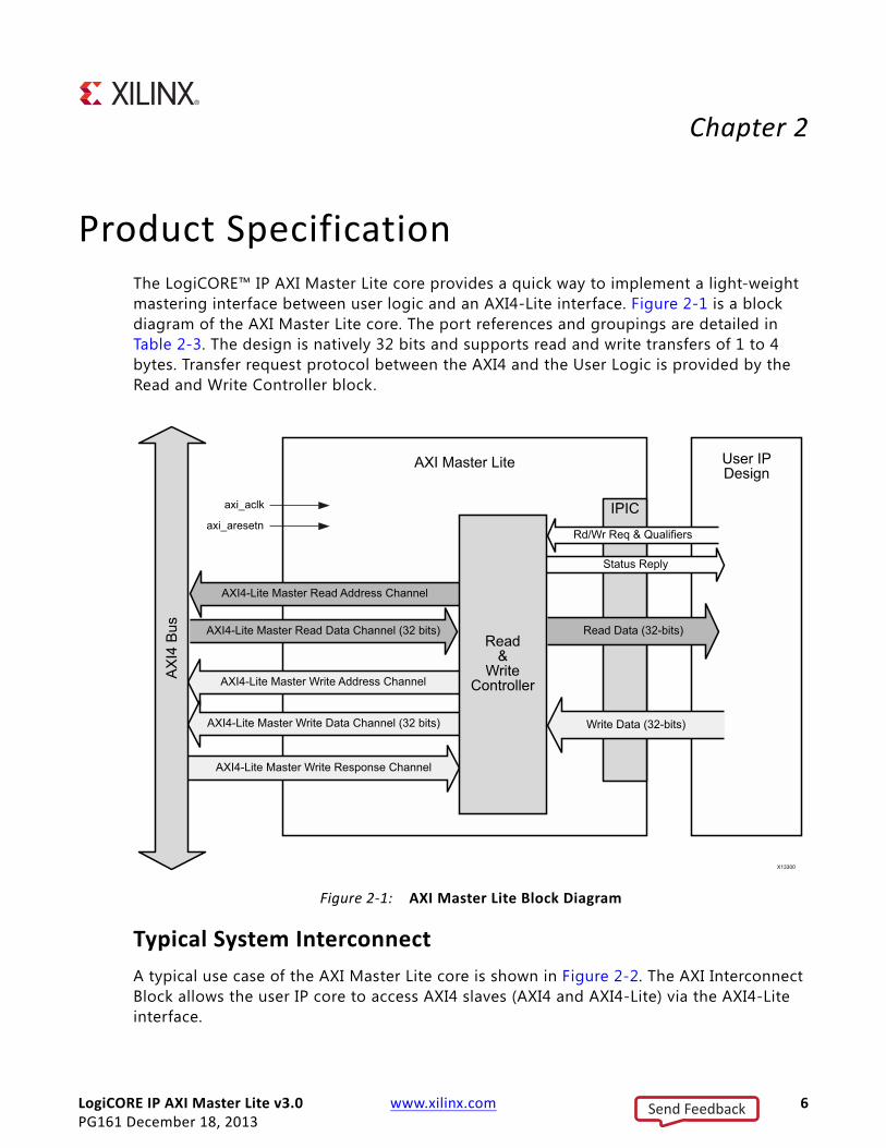
Product SpecificationThe LogiCORE™ IP AXI Master Lite core provides a quick way to implement a light-weight mastering interface between user logic and an AXI4-Lite interface. Figure 2-1 is a block diagram of the AXI Master Lite core. The port references and groupings are detailed in Table 2-3. The design is natively 32 bits and supports read and write transfers of 1 to 4 bytes. Transfer request protocol between the AXI4 and the User Logic is provided by the Read and Write Controller block.
Typical System Interconnect
A typical use case of the AXI Master Lite core is shown in Figure 2-2. The AXI Interconnect Block allows the user IP core to access AXI4 slaves (AXI4 and AXI4-Lite) via the AXI4-Lite interface.
X-Ref Target - Figure 2-1
Figure 2‐1: AXI Master Lite Block Diagram
Send Feedback

LogiCORE IP AXI Master Lite v3.0 www.xilinx.com 7PG161 December 18, 2013
Chapter 2: Product Specification
StandardsThe AXI interfaces conform to the Advanced Microcontroller Bus Architecture (AMBA®) AXI version 4 specif ication from Advanced RISC Machine (ARM®), including the AXI4-Lite control register interface subset. See ARM AMBA AXI Protocol v2.0 [Ref 6].
PerformanceThis section provides performance information for the AXI Master Lite core.
X-Ref Target - Figure 2-2
Figure 2‐2: AXI Interconnect Block (AXI_Interconnect)
Send Feedback

LogiCORE IP AXI Master Lite v3.0 www.xilinx.com 8PG161 December 18, 2013
Chapter 2: Product Specification
Maximum Frequencies
Table 2-1 shows the targeted design clock frequencies of the AXI Master Lite core.
Values for the Zynq® family of devices with a Kintex® or Artix® base are expected to be similar. The maximum achievable clock frequency and resource utilization estimates may be different from those shown due to tool options, FPGA speed and logic utilization, and other factors.
Throughput
No information is currently provided for this core.
Power
No information is currently provided for this core.
Resource UtilizationBecause the AXI4-Lite Master interface is used with other design modules in the devices, the utilization and timing numbers reported in this section are estimates. Because the AXI4-Lite Master interface is combined with other design elements, resource utilization and timing may vary from the results reported here.
The resource utilization of this version of the AXI Master Lite core is shown here for example configurations. The slave attachment was synthesized using Vivado® synthesis. The resource utilization report was then used as the source data for the table.
Resource utilization numbers for the AXI Master Lite core are shown for the 7 series FPGA families in Table 2-2. These values were generated using the Xilinx Vivado Suite. The Zynq family of devices with a Kintex or Artix base are expected to have similar utilization results
Table 2‐1: Targeted Frequencies
Family Fmax (Mhz)
Virtex-7 180
Kintex-7 150
Artix-7 120
Send Feedback
LogiCORE IP AXI Master Lite v3.0 www.xilinx.com 9PG161 December 18, 2013
Chapter 2: Product Specification
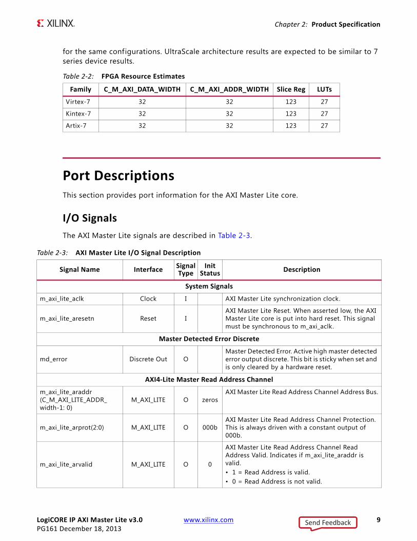
for the same configurations. UltraScale architecture results are expected to be similar to 7 series device results.
Port DescriptionsThis section provides port information for the AXI Master Lite core.
I/O Signals
The AXI Master Lite signals are described in Table 2-3.
Table 2‐2: FPGA Resource Estimates
Family C_M_AXI_DATA_WIDTH C_M_AXI_ADDR_WIDTH Slice Reg LUTs
Virtex-7 32 32 123 27
Kintex-7 32 32 123 27
Artix-7 32 32 123 27
Table 2‐3: AXI Master Lite I/O Signal Description
Signal Name InterfaceSignalType
InitStatus Description
System Signals
m_axi_lite_aclk Clock I AXI Master Lite synchronization clock.
m_axi_lite_aresetn Reset IAXI Master Lite Reset. When asserted low, the AXI Master Lite core is put into hard reset. This signal must be synchronous to m_axi_aclk.
Master Detected Error Discrete
md_error Discrete Out OMaster Detected Error. Active high master detected error output discrete. This bit is sticky when set and is only cleared by a hardware reset.
AXI4‐Lite Master Read Address Channel
m_axi_lite_araddr(C_M_AXI_LITE_ADDR_width-1: 0)
M_AXI_LITE O zerosAXI Master Lite Read Address Channel Address Bus.
m_axi_lite_arprot(2:0) M_AXI_LITE O 000bAXI Master Lite Read Address Channel Protection. This is always driven with a constant output of 000b.
m_axi_lite_arvalid M_AXI_LITE O 0
AXI Master Lite Read Address Channel Read Address Valid. Indicates if m_axi_lite_araddr is valid.• 1 = Read Address is valid.• 0 = Read Address is not valid.
Send Feedback
LogiCORE IP AXI Master Lite v3.0 www.xilinx.com 10PG161 December 18, 2013
Chapter 2: Product Specification
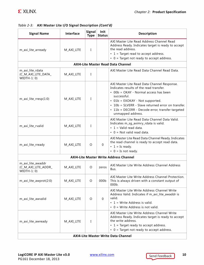
m_axi_lite_arready M_AXI_LITE I
AXI Master Lite Read Address Channel Read Address Ready. Indicates target is ready to accept the read address.• 1 = Target read to accept address.• 0 = Target not ready to accept address.
AXI4‐Lite Master Read Data Channel
m_axi_lite_rdata(C_M_AXI_LITE_DATA_WIDTH-1: 0)
M_AXI_LITE IAXI Master Lite Read Data Channel Read Data.
m_axi_lite_rresp(1:0) M_AXI_LITE I
AXI Master Lite Read Data Channel Response. Indicates results of the read transfer.• 00b = OKAY - Normal access has been
successful.• 01b = EXOKAY - Not supported.• 10b = SLVERR - Slave returned error on transfer.• 11b = DECERR - Decode error, transfer targeted
unmapped address.
m_axi_lite_rvalid M_AXI_LITE I
AXI Master Lite Read Data Channel Data Valid. Indicates m_sg_aximry_rdata is valid.• 1 = Valid read data.• 0 = Not valid read data.
m_axi_lite_rready M_AXI_LITE O 0
AXI Master Lite Read Data Channel Ready. Indicates the read channel is ready to accept read data.• 1 = Is ready.• 0 = Is not ready.
AXI4‐Lite Master Write Address Channel
m_axi_lite_awaddr(C_M_AXI_LITE_ADDR_WIDTH-1: 0)
M_AXI_LITE O zeros AXI Master Lite Write Address Channel Address Bus.
m_axi_lite_awprot(2:0) M_AXI_LITE O 000bAXI Master Lite Write Address Channel Protection. This is always driven with a constant output of 000b.
m_axi_lite_awvalid M_AXI_LITE O 0
AXI Master Lite Write Address Channel Write Address Valid. Indicates if m_axi_lite_awaddr is valid.• 1 = Write Address is valid.• 0 = Write Address is not valid.
m_axi_lite_awready M_AXI_LITE I
AXI Master Lite Write Address Channel Write Address Ready. Indicates target is ready to accept the write address.• 1 = Target ready to accept address.• 0 = Target not ready to accept address.
AXI4‐Lite Master Write Data Channel
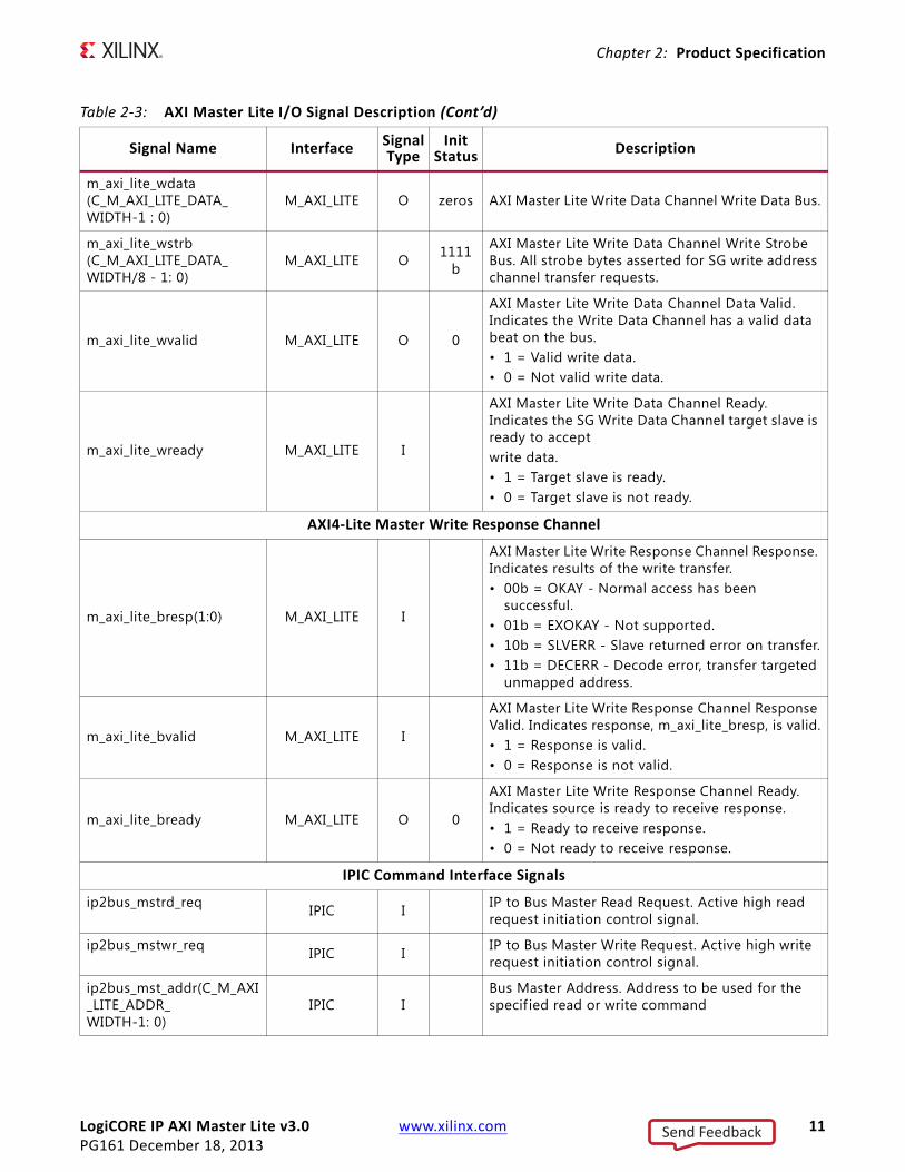
Table 2‐3: AXI Master Lite I/O Signal Description (Cont’d)
Signal Name Interface SignalType
InitStatus
Description
Send Feedback
LogiCORE IP AXI Master Lite v3.0 www.xilinx.com 11PG161 December 18, 2013
Chapter 2: Product Specification
m_axi_lite_wdata(C_M_AXI_LITE_DATA_WIDTH-1 : 0)
M_AXI_LITE O zeros AXI Master Lite Write Data Channel Write Data Bus.
m_axi_lite_wstrb(C_M_AXI_LITE_DATA_WIDTH/8 - 1: 0)
M_AXI_LITE O 1111b
AXI Master Lite Write Data Channel Write Strobe Bus. All strobe bytes asserted for SG write address channel transfer requests.
m_axi_lite_wvalid M_AXI_LITE O 0
AXI Master Lite Write Data Channel Data Valid. Indicates the Write Data Channel has a valid data beat on the bus.• 1 = Valid write data.• 0 = Not valid write data.
m_axi_lite_wready M_AXI_LITE I
AXI Master Lite Write Data Channel Ready. Indicates the SG Write Data Channel target slave is ready to acceptwrite data.• 1 = Target slave is ready.• 0 = Target slave is not ready.
AXI4‐Lite Master Write Response Channel
m_axi_lite_bresp(1:0) M_AXI_LITE I
AXI Master Lite Write Response Channel Response. Indicates results of the write transfer.• 00b = OKAY - Normal access has been
successful.• 01b = EXOKAY - Not supported.• 10b = SLVERR - Slave returned error on transfer.• 11b = DECERR - Decode error, transfer targeted
unmapped address.
m_axi_lite_bvalid M_AXI_LITE I
AXI Master Lite Write Response Channel Response Valid. Indicates response, m_axi_lite_bresp, is valid.• 1 = Response is valid.• 0 = Response is not valid.
m_axi_lite_bready M_AXI_LITE O 0
AXI Master Lite Write Response Channel Ready. Indicates source is ready to receive response.• 1 = Ready to receive response.• 0 = Not ready to receive response.
IPIC Command Interface Signals
ip2bus_mstrd_req IPIC I IP to Bus Master Read Request. Active high read request initiation control signal.
ip2bus_mstwr_req IPIC I IP to Bus Master Write Request. Active high write request initiation control signal.
ip2bus_mst_addr(C_M_AXI_LITE_ADDR_WIDTH-1: 0)
IPIC IBus Master Address. Address to be used for the specif ied read or write command
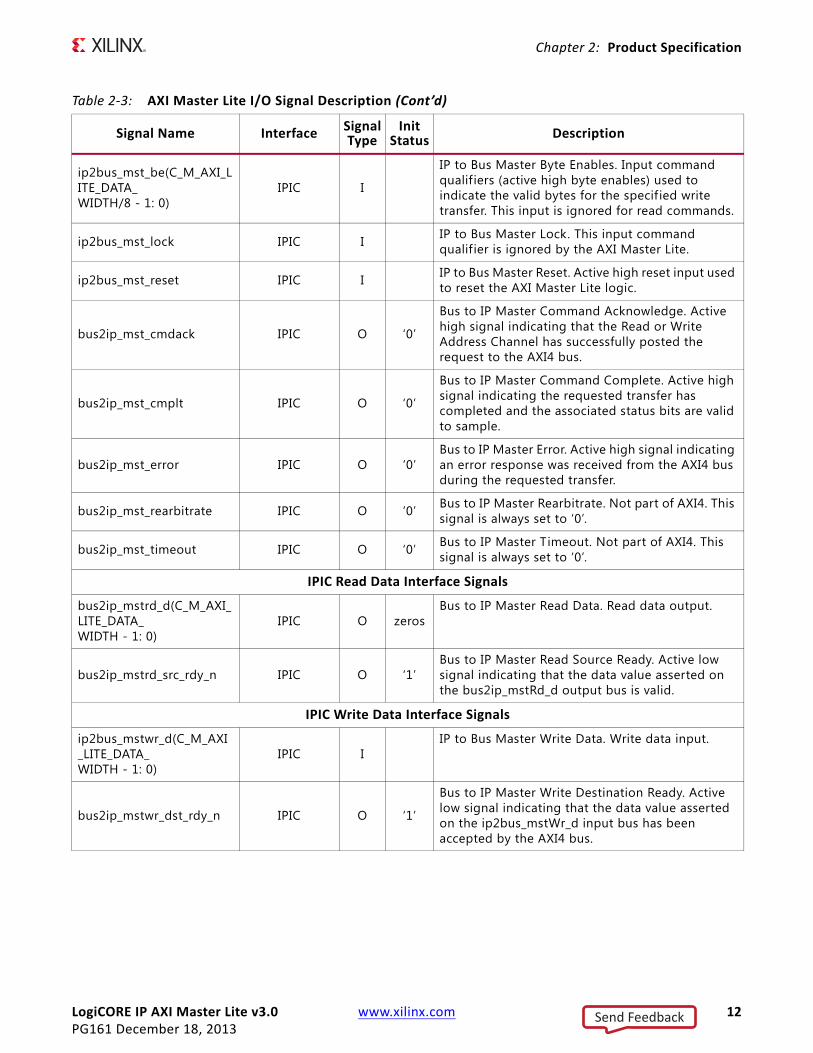
Table 2‐3: AXI Master Lite I/O Signal Description (Cont’d)
Signal Name Interface SignalType
InitStatus
Description
Send Feedback
LogiCORE IP AXI Master Lite v3.0 www.xilinx.com 12PG161 December 18, 2013
Chapter 2: Product Specification
ip2bus_mst_be(C_M_AXI_LITE_DATA_WIDTH/8 - 1: 0)
IPIC I
IP to Bus Master Byte Enables. Input command qualif iers (active high byte enables) used to indicate the valid bytes for the specif ied write transfer. This input is ignored for read commands.
ip2bus_mst_lock IPIC I IP to Bus Master Lock. This input command qualif ier is ignored by the AXI Master Lite.
ip2bus_mst_reset IPIC I IP to Bus Master Reset. Active high reset input used to reset the AXI Master Lite logic.
bus2ip_mst_cmdack IPIC O ‘0’
Bus to IP Master Command Acknowledge. Active high signal indicating that the Read or Write Address Channel has successfully posted the request to the AXI4 bus.
bus2ip_mst_cmplt IPIC O ‘0’
Bus to IP Master Command Complete. Active high signal indicating the requested transfer has completed and the associated status bits are valid to sample.
bus2ip_mst_error IPIC O ‘0’Bus to IP Master Error. Active high signal indicating an error response was received from the AXI4 bus during the requested transfer.
bus2ip_mst_rearbitrate IPIC O ‘0’ Bus to IP Master Rearbitrate. Not part of AXI4. This signal is always set to ‘0’.
bus2ip_mst_timeout IPIC O ‘0’ Bus to IP Master Timeout. Not part of AXI4. This signal is always set to ‘0’.
IPIC Read Data Interface Signals
bus2ip_mstrd_d(C_M_AXI_LITE_DATA_WIDTH - 1: 0)
IPIC O zerosBus to IP Master Read Data. Read data output.
bus2ip_mstrd_src_rdy_n IPIC O ‘1’Bus to IP Master Read Source Ready. Active low signal indicating that the data value asserted on the bus2ip_mstRd_d output bus is valid.
IPIC Write Data Interface Signals
ip2bus_mstwr_d(C_M_AXI_LITE_DATA_WIDTH - 1: 0)
IPIC IIP to Bus Master Write Data. Write data input.
bus2ip_mstwr_dst_rdy_n IPIC O ‘1’
Bus to IP Master Write Destination Ready. Active low signal indicating that the data value asserted on the ip2bus_mstWr_d input bus has been accepted by the AXI4 bus.
Table 2‐3: AXI Master Lite I/O Signal Description (Cont’d)
Signal Name Interface SignalType
InitStatus
Description
Send Feedback
LogiCORE IP AXI Master Lite v3.0 www.xilinx.com 13PG161 December 18, 2013
Chapter 3
Designing with the CoreThis chapter includes guidelines and additional information to facilitate designing with the core.
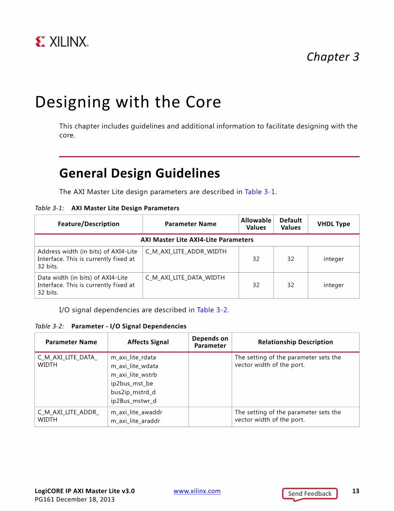
General Design GuidelinesThe AXI Master Lite design parameters are described in Table 3-1.
I/O signal dependencies are described in Table 3-2.
Table 3‐1: AXI Master Lite Design Parameters
Feature/Description Parameter NameAllowable Values
Default Values
VHDL Type
AXI Master Lite AXI4‐Lite Parameters
Address width (in bits) of AXI4-Lite Interface. This is currently f ixed at 32 bits.
C_M_AXI_LITE_ADDR_WIDTH32 32 integer
Data width (in bits) of AXI4-Lite Interface. This is currently f ixed at 32 bits.
C_M_AXI_LITE_DATA_WIDTH32 32 integer
Table 3‐2: Parameter ‐ I/O Signal Dependencies
Parameter Name Affects Signal Depends on Parameter
Relationship Description
C_M_AXI_LITE_DATA_WIDTH
m_axi_lite_rdatam_axi_lite_wdatam_axi_lite_wstrbip2bus_mst_bebus2ip_mstrd_dip2Bus_mstwr_d
The setting of the parameter sets the vector width of the port.
C_M_AXI_LITE_ADDR_WIDTH
m_axi_lite_awaddrm_axi_lite_araddr
The setting of the parameter sets the vector width of the port.
Send Feedback

LogiCORE IP AXI Master Lite v3.0 www.xilinx.com 14PG161 December 18, 2013
Chapter 3: Designing with the Core
The parameters are described in Table 3-3
ClockingThe AXI Master Lite core uses a single clock for logic synchronization. This clock is input on the m_axi_lite_aclk input port. All interfaces for the core are required to be synchronized to this clock. The AXI Master Lite core has been simulation tested with an m_axi_lite_aclk frequency range of 10 MHz to 200 MHz. Actual Fmax achieved in a hardware implementation may vary.
ResetsAn active low reset assertion on the AXI Master Lite m_axi_lite_aresetn input resets the entire AXI Master Lite core. This is considered a hardware reset, and there are no graceful completions of AXI4 transfers in progress. A hardware reset initializes all AXI Master Lite internal logic to power-on conditions. It is required that the m_axi_lite_aresetn input is synchronous to the m_axi_lite_aclk master clock input and is asserted for the minimum number of clocks stated in Table 3-4. Table 3-4 also indicates the stabilization time for AXI Master Lite outputs reacting to a reset condition.
Table 3‐3: Parameter Descriptions
Parameter Name TypeAllowed Values
Definition Description
C_M_AXI_LITE_ADDR_WIDTH
Integer 32 (default) Address bus width of attached AXI on the AXI AXI Master Lite interface
Used to size the Read Address and Write Address Channels of the AXI Master Lite AXI4 Interface. The EDK tool suite assigns this parameter a f ixed value of 32.
C_M_AXI_LITE_DATA_WIDTH
Integer 32 (default) Read Data bus width of attached AXI4 on the AXI Master Lite interface
Used to size the Read Data and Write Data Channels of the AXI Master Lite interface. The EDK tool suite assigns this parameter a fixed value of 32.
Table 3‐4: Reset Assertion/Deassertion Stabilization Times
Description Value Applicable Signal
Minimum assertion time 8 clocks (m_axi_lite_aclk)
axi_resetn input
Reset assertion to output signals in reset state (maximum)
3 clocks (m_axi_lite_aclk)
All output signals
Reset deassertion to normal operation state (maximum)
3 clocks (m_axi_lite_aclk)
All output signals
Send Feedback
LogiCORE IP AXI Master Lite v3.0 www.xilinx.com 15PG161 December 18, 2013
Chapter 3: Designing with the Core
Protocol DescriptionNo information is currently provided for this core.
Transaction Timing Examples
This section shows timing relationships for AXI4-Lite and the IPIC interface signals during read and write transfers. Only single data beat transfers of 1 to 4 bytes are supported by the AXI Master Lite core.
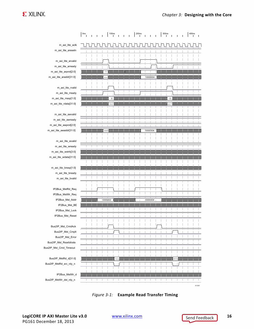
Single Data Beat Read Operation
Two single beat read cycles are shown in Figure 3-1. The f irst cycle shows the AXI Slave accepting the read address and qualif iers in one clock cycle and presenting the read data in the next clock cycle. The second read transfer indicates a delayed address acceptance sequence and a delayed read data valid by the AXI Slave device.
Send Feedback
LogiCORE IP AXI Master Lite v3.0 www.xilinx.com 16PG161 December 18, 2013
Chapter 3: Designing with the Core
X-Ref Target - Figure 3-1
Figure 3‐1: Example Read Transfer Timing
Send Feedback
LogiCORE IP AXI Master Lite v3.0 www.xilinx.com 17PG161 December 18, 2013
Chapter 3: Designing with the Core
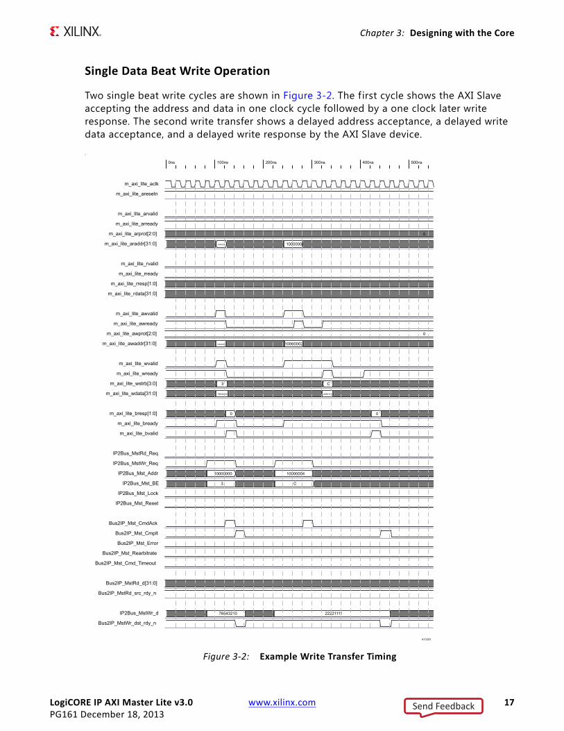
Single Data Beat Write Operation
Two single beat write cycles are shown in Figure 3-2. The f irst cycle shows the AXI Slave accepting the address and data in one clock cycle followed by a one clock later write response. The second write transfer shows a delayed address acceptance, a delayed write data acceptance, and a delayed write response by the AXI Slave device.
SX-Ref Target - Figure 3-2
Figure 3‐2: Example Write Transfer Timing
Send Feedback
LogiCORE IP AXI Master Lite v3.0 www.xilinx.com 18PG161 December 18, 2013
Chapter 3: Designing with the Core
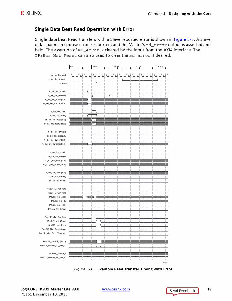
Single Data Beat Read Operation with Error
Single data beat Read transfers with a Slave reported error is shown in Figure 3-3. A Slave data channel response error is reported, and the Master’s md_error output is asserted and held. The assertion of md_error is cleared by the input from the AXI4 interface. The IP2Bus_Mst_Reset can also used to clear the md_error if desired.
SX-Ref Target - Figure 3-3
Figure 3‐3: Example Read Transfer Timing with Error
Send Feedback
LogiCORE IP AXI Master Lite v3.0 www.xilinx.com 19PG161 December 18, 2013
Chapter 3: Designing with the Core
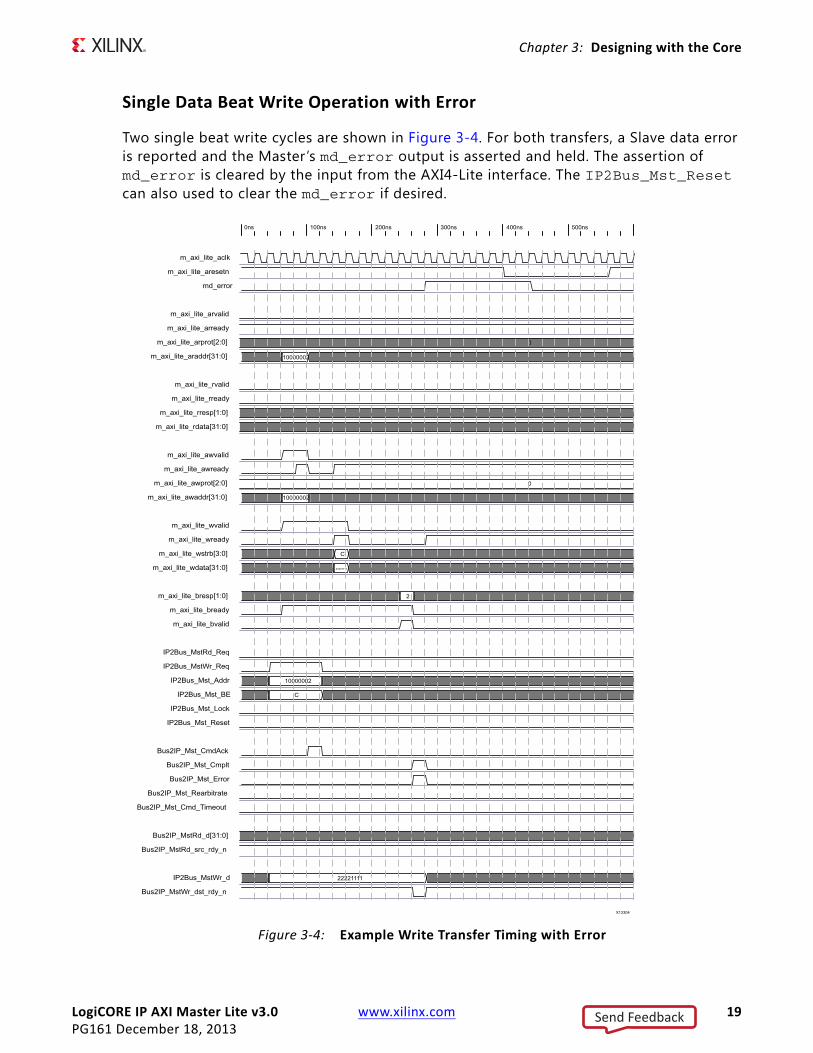
Single Data Beat Write Operation with Error
Two single beat write cycles are shown in Figure 3-4. For both transfers, a Slave data error is reported and the Master’s md_error output is asserted and held. The assertion of md_error is cleared by the input from the AXI4-Lite interface. The IP2Bus_Mst_Reset can also used to clear the md_error if desired.X-Ref Target - Figure 3-4
Figure 3‐4: Example Write Transfer Timing with Error
Send Feedback
LogiCORE IP AXI Master Lite v3.0 www.xilinx.com 20PG161 March 20, 2013
Chapter 4
Customizing and Generating the CoreAXI Master Lite is a helper core, so no specific core graphical user interface is available. The core needs to be instantiated in the user design and package through Vivado® IP Packager. The interface is available for the user design, which can optionally include parameters for configuring the AXI Master Lite core.
Send Feedback
LogiCORE IP AXI Master Lite v3.0 www.xilinx.com 21PG161 December 18, 2013
Chapter 5
Constraining the CoreNo constraints are available for this core. When the AXI Master Lite core is instantiated in a user design, the modif ied design can accommodate any user-provided constraints.
Send Feedback
LogiCORE IP AXI Master Lite v3.0 www.xilinx.com 22PG161 December 18, 2013
Chapter 6
SimulationFor comprehensive information about Vivado® simulation components, as well as information about using supported third-party tools, see the Vivado Design Suite User Guide: Logic Simulation (UG900) [Ref 2].
Send Feedback
LogiCORE IP AXI Master Lite v3.0 www.xilinx.com 23PG161 December 18, 2013
Chapter 7
Synthesis and ImplementationFor details about synthesis and implementation, see “Synthesizing IP” and “Implementing IP” in the Vivado Design Suite User Guide: Designing with IP (UG896) [Ref 5].
Send Feedback
LogiCORE IP AXI Master Lite v3.0 www.xilinx.com 24PG161 December 18, 2013
Chapter 8
Example DesignNo example design is provided with this core.
Send Feedback
LogiCORE IP AXI Master Lite v3.0 www.xilinx.com 25PG161 December 18, 2013
Chapter 9
Test Bench No test bench is provided with this core.
Send Feedback
LogiCORE IP AXI Master Lite v3.0 www.xilinx.com 26PG161 December 18, 2013
Appendix A
DebuggingThis appendix includes details about resources available on the Xilinx Support website and debugging tools.
Finding Help on Xilinx.comTo help in the design and debug process when using the AXI Master Lite core, the Xilinx Support web page (www.xilinx.com/support) contains key resources such as product documentation, release notes, answer records, information about known issues, and links for opening a Technical Support WebCase.
Documentation
This product guide is the main document associated with the AXI Master Lite core. This guide, along with documentation related to all products that aid in the design process, can be found on the Xilinx Support web page (www.xilinx.com/support) or by using the Xilinx Documentation Navigator.
Download the Xilinx Documentation Navigator from the Design Tools tab on the Downloads page (www.xilinx.com/download). For more information about this tool and the features available, open the online help after installation.
Solution Centers
See the Xilinx Solution Centers for support on devices, software tools, and intellectual property at all stages of the design cycle. Topics include design assistance, advisories, and troubleshooting tips.
Answer Records
Answer Records include information about commonly encountered problems, helpful information on how to resolve these problems, and any known issues with a Xilinx product. Answer Records are created and maintained daily ensuring that users have access to the most accurate information available.
Send Feedback
LogiCORE IP AXI Master Lite v3.0 www.xilinx.com 27PG161 December 18, 2013
Appendix A: Debugging
Answer Records for this core can also be located by using the Search Support box on the main Xilinx support web page. To maximize your search results, use proper keywords such as
• Product name
• Tool messages
• Summary of the issue encountered
A filter search is available after results are returned to further target the results.
Master Answer Record for the AXI Master Lite core
AR 55014
Contacting Technical Support
Xilinx provides technical support at www.xilinx.com/support for this LogiCORE™ IP product when used as described in the product documentation. Xilinx cannot guarantee timing, functionality, or support of product if implemented in devices that are not defined in the documentation, if customized beyond that allowed in the product documentation, or if changes are made to any section of the design labeled DO NOT MODIFY.
To contact Xilinx Technical Support:
1. Navigate to www.xilinx.com/support.
2. Open a WebCase by selecting the WebCase link located under Support Quick Links.
When opening a WebCase, include:
• Target FPGA including package and speed grade.
• All applicable Xilinx Design Tools and simulator software versions.
• Additional f iles based on the specif ic issue might also be required. See the relevant sections in this debug guide for guidelines about which f ile(s) to include with the WebCase.
Debug ToolsThere are many tools available to address AXI Master Lite design issues. It is important to know which tools are useful for debugging various situations.
Send Feedback
LogiCORE IP AXI Master Lite v3.0 www.xilinx.com 28PG161 December 18, 2013
Appendix A: Debugging
Vivado Lab Tools
Vivado® inserts logic analyzer and virtual I/O cores directly into your design. Vivado Lab Tools allows you to set trigger conditions to capture application and integrated block port signals in hardware. Captured signals can then be analyzed. This feature represents the functionality in the Vivado IDE that is used for logic debugging and validation of a design running in Xilinx FPGA devices in hardware.
The Vivado logic analyzer is used to interact with the logic debug LogiCORE IP cores, including:
• ILA 2.0 (and later versions)
• VIO 2.0 (and later versions)
Interface DebugThe AXI Master Lite core is a helper core and should be instantiated in another AXI master core that is part of the system. The interface of the parent core should have additional information about interface debug.
Note: The Master AXI interface address, data, and response channels should be monitored while debugging the scenarios.
AXI4‐Lite Interfaces
Initiate a read transaction towards targeted slave registers. To check if the interface is functional, monitor the m_axi_lite_arvalid, m_axi_lite_araddr[31:0], and m_axi_lite_rready signals. The slave should respond with valid m_axi_lite_arready, m_axi_lite_rvalid, m_axi_lite_rresp[1:0], and m_axi_lite_rdata[31:0] signals. The assertion of these signals indicates that the read transaction from the master is completed. If the interface is unresponsive, ensure that the following conditions are met:
• The m_axi_lite_aclk input is connected and toggling.
• The interface is not being held in reset, and m_axi_lite_aresent is an active-Low reset.
• The main core clocks are toggling and that the enables are also asserted.
• If the simulation has been run, verify in simulation and/or a ChipScope debugging tool capture that the waveform is correct for accessing the AXI4-Lite interface.
Send Feedback
LogiCORE IP AXI Master Lite v3.0 www.xilinx.com 29PG161 December 18, 2013
Appendix B
Additional Resources
Xilinx Resources
For support resources such as Answers, Documentation, Downloads, and Forums, see the Xilinx Support website at:
www.xilinx.com/support.
For a glossary of technical terms used in Xilinx documentation, see:
www.xilinx.com/company/terms.htm.
ReferencesThese documents provide supplemental material useful with this product guide:
1. AMBA AXI4-Stream Protocol Specification
2. Vivado Design Suite User Guide - Logic Simulation (UG900)
3. Vivado Design Suite User Guide - Implementation (UG904)
4. ISE to Vivado Design Suite Migration Guide (UG911)
5. Vivado Design Suite User Guide: Designing with IP (UG896)
6. ARM® AMBA® AXI Protocol v2.0
7. 7 Series FPGA Overview (DS180)
8. LogiCORE IP AXI Interconnect Product Guide (PG059)
Send Feedback
LogiCORE IP AXI Master Lite v3.0 www.xilinx.com 30PG161 December 18, 2013
Appendix B: Additional Resources
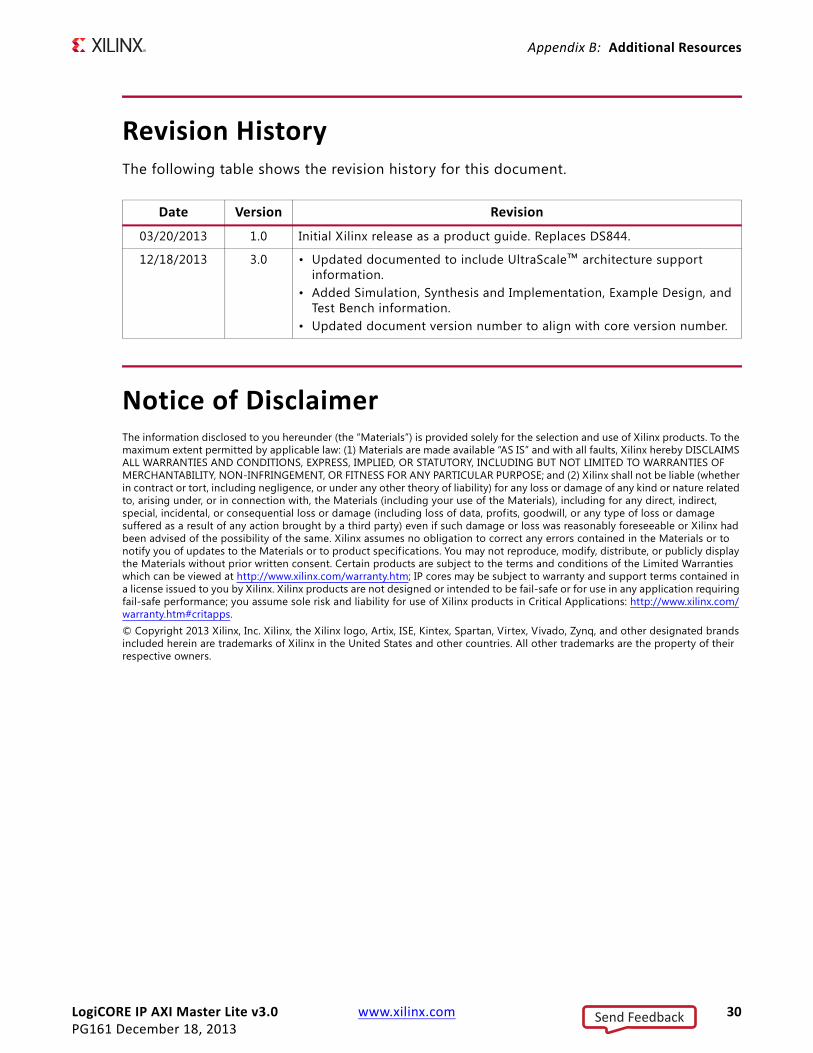
Revision HistoryThe following table shows the revision history for this document.
Notice of DisclaimerThe information disclosed to you hereunder (the “Materials”) is provided solely for the selection and use of Xilinx products. To the maximum extent permitted by applicable law: (1) Materials are made available “AS IS” and with all faults, Xilinx hereby DISCLAIMS ALL WARRANTIES AND CONDITIONS, EXPRESS, IMPLIED, OR STATUTORY, INCLUDING BUT NOT LIMITED TO WARRANTIES OF MERCHANTABILITY, NON-INFRINGEMENT, OR FITNESS FOR ANY PARTICULAR PURPOSE; and (2) Xilinx shall not be liable (whether in contract or tort, including negligence, or under any other theory of liability) for any loss or damage of any kind or nature related to, arising under, or in connection with, the Materials (including your use of the Materials), including for any direct, indirect, special, incidental, or consequential loss or damage (including loss of data, profits, goodwill, or any type of loss or damage suffered as a result of any action brought by a third party) even if such damage or loss was reasonably foreseeable or Xilinx had been advised of the possibility of the same. Xilinx assumes no obligation to correct any errors contained in the Materials or to notify you of updates to the Materials or to product specifications. You may not reproduce, modify, distribute, or publicly display the Materials without prior written consent. Certain products are subject to the terms and conditions of the Limited Warranties which can be viewed at http://www.xilinx.com/warranty.htm; IP cores may be subject to warranty and support terms contained in a license issued to you by Xilinx. Xilinx products are not designed or intended to be fail-safe or for use in any application requiring fail-safe performance; you assume sole risk and liability for use of Xilinx products in Critical Applications: http://www.xilinx.com/warranty.htm#critapps.© Copyright 2013 Xilinx, Inc. Xilinx, the Xilinx logo, Artix, ISE, Kintex, Spartan, Virtex, Vivado, Zynq, and other designated brands included herein are trademarks of Xilinx in the United States and other countries. All other trademarks are the property of their respective owners.
Date Version Revision
03/20/2013 1.0 Initial Xilinx release as a product guide. Replaces DS844.
12/18/2013 3.0 • Updated documented to include UltraScale™ architecture support information.
• Added Simulation, Synthesis and Implementation, Example Design, and Test Bench information.
• Updated document version number to align with core version number.
Send Feedback