logicore™ ip fibre channel user guide v3 - xilinxlogicore™ ip fibre channel user guide v3.5 user...
TRANSCRIPT
LogiCORE™ IPFibre Channel User Guide v3.5
User Guide
UG136 April 19, 2010
Discon
tinue
d IP
Fibre Channel User Guide www.xilinx.com UG136 April 19, 2010
Xilinx is providing this product documentation, hereinafter “Information,” to you “AS IS” with no warranty of any kind, express or implied. Xilinx makes no representation that the Information, or any particular implementation thereof, is free from any claims of infringement. You are responsible for obtaining any rights you may require for any implementation based on the Information. All specifications are subject to change without notice.
XILINX EXPRESSLY DISCLAIMS ANY WARRANTY WHATSOEVER WITH RESPECT TO THE ADEQUACY OF THE INFORMATION OR ANY IMPLEMENTATION BASED THEREON, INCLUDING BUT NOT LIMITED TO ANY WARRANTIES OR REPRESENTATIONS THAT THIS IMPLEMENTATION IS FREE FROM CLAIMS OF INFRINGEMENT AND ANY IMPLIED WARRANTIES OF MERCHANTABILITY OR FITNESS FOR A PARTICULAR PURPOSE. Except as stated herein, none of the Information may be copied, reproduced, distributed, republished, downloaded, displayed, posted, or transmitted in any form or by any means including, but not limited to, electronic, mechanical, photocopying, recording, or otherwise, without the prior written consent of Xilinx.
© 2004-2010 Xilinx, Inc. XILINX, the Xilinx logo, Virtex, Spartan, ISE and other designated brands included herein are trademarks of Xilinx in the United States and other countries. The PowerPC name and logo are registered trademarks of IBM Corp. and used under license. All other trademarks are the property of their respective owners.
Revision History
Date Version Revision
6/29/04 1.0 Initial Xilinx release.
4/28/05 2.0 Updated for core version 2.0 and Xilinx tools v7.1i.
1/18/06 2.1 Updated core version to 2.1 and Xilinx tools 8.2i.
2/15/07 3.1 Updated core version to 3.1 and Xilinx tools to v9.1i.
8/8/07 3.2 Updated core version to 3.2 and Xilinx tools to v9.2i.
3/24/08 3.5 Updated core version to 3.3 and Xilinx tools to v10.1.
4/24/09 3.6 Updated core version to 3.4 and Xilinx tools to v11.1.
4/19/10 3.7 Updated core version to 3.5 and Xilinx tools to v12.1.
Discon
tinue
d IP

Fibre Channel User Guide www.xilinx.com 3UG136 April 19, 2010
Preface: About This GuideGuide Contents . . . . . . . . . . . . . . . . . . . . . . . . . . . . . . . . . . . . . . . . . . . . . . . . . . . . . . . . . . . . . 11Conventions . . . . . . . . . . . . . . . . . . . . . . . . . . . . . . . . . . . . . . . . . . . . . . . . . . . . . . . . . . . . . . . . 12
Typographical . . . . . . . . . . . . . . . . . . . . . . . . . . . . . . . . . . . . . . . . . . . . . . . . . . . . . . . . . . . . 12Online Document . . . . . . . . . . . . . . . . . . . . . . . . . . . . . . . . . . . . . . . . . . . . . . . . . . . . . . . . . 13
Chapter 1: IntroductionAbout the Core . . . . . . . . . . . . . . . . . . . . . . . . . . . . . . . . . . . . . . . . . . . . . . . . . . . . . . . . . . . . . . 15Obtaining the Core . . . . . . . . . . . . . . . . . . . . . . . . . . . . . . . . . . . . . . . . . . . . . . . . . . . . . . . . . . 15Recommended Experience. . . . . . . . . . . . . . . . . . . . . . . . . . . . . . . . . . . . . . . . . . . . . . . . . . . 15Additional Core Resources . . . . . . . . . . . . . . . . . . . . . . . . . . . . . . . . . . . . . . . . . . . . . . . . . . 16Technical Support. . . . . . . . . . . . . . . . . . . . . . . . . . . . . . . . . . . . . . . . . . . . . . . . . . . . . . . . . . . 16Providing Feedback . . . . . . . . . . . . . . . . . . . . . . . . . . . . . . . . . . . . . . . . . . . . . . . . . . . . . . . . . 16
Documentation . . . . . . . . . . . . . . . . . . . . . . . . . . . . . . . . . . . . . . . . . . . . . . . . . . . . . . . . . . . 16Core . . . . . . . . . . . . . . . . . . . . . . . . . . . . . . . . . . . . . . . . . . . . . . . . . . . . . . . . . . . . . . . . . . . . 16
Chapter 2: Core ArchitectureSystem Overview . . . . . . . . . . . . . . . . . . . . . . . . . . . . . . . . . . . . . . . . . . . . . . . . . . . . . . . . . . . 17
Core Components . . . . . . . . . . . . . . . . . . . . . . . . . . . . . . . . . . . . . . . . . . . . . . . . . . . . . . . . 17Core Interfaces . . . . . . . . . . . . . . . . . . . . . . . . . . . . . . . . . . . . . . . . . . . . . . . . . . . . . . . . . . . . . . 20
Optional Interfaces . . . . . . . . . . . . . . . . . . . . . . . . . . . . . . . . . . . . . . . . . . . . . . . . . . . . . . . . 20Client Side Interface Signals . . . . . . . . . . . . . . . . . . . . . . . . . . . . . . . . . . . . . . . . . . . . . . . . 26Management Interface Signals . . . . . . . . . . . . . . . . . . . . . . . . . . . . . . . . . . . . . . . . . . . . . . 27Speed Negotiation Signals . . . . . . . . . . . . . . . . . . . . . . . . . . . . . . . . . . . . . . . . . . . . . . . . . 27Clock and Reset Signals . . . . . . . . . . . . . . . . . . . . . . . . . . . . . . . . . . . . . . . . . . . . . . . . . . . 28Physical Interface Signals . . . . . . . . . . . . . . . . . . . . . . . . . . . . . . . . . . . . . . . . . . . . . . . . . . 28Optics Control and Status Signals . . . . . . . . . . . . . . . . . . . . . . . . . . . . . . . . . . . . . . . . . . . 30
Chapter 3: Generating the CoreGraphical User Interface . . . . . . . . . . . . . . . . . . . . . . . . . . . . . . . . . . . . . . . . . . . . . . . . . . . . 31
Component Name . . . . . . . . . . . . . . . . . . . . . . . . . . . . . . . . . . . . . . . . . . . . . . . . . . . . . . . . 31Management Interface . . . . . . . . . . . . . . . . . . . . . . . . . . . . . . . . . . . . . . . . . . . . . . . . . . . . . 32Statistics Gathering . . . . . . . . . . . . . . . . . . . . . . . . . . . . . . . . . . . . . . . . . . . . . . . . . . . . . . . 32Operation Speed . . . . . . . . . . . . . . . . . . . . . . . . . . . . . . . . . . . . . . . . . . . . . . . . . . . . . . . . . . 32BB Credit Management . . . . . . . . . . . . . . . . . . . . . . . . . . . . . . . . . . . . . . . . . . . . . . . . . . . . 32Speed Negotiation . . . . . . . . . . . . . . . . . . . . . . . . . . . . . . . . . . . . . . . . . . . . . . . . . . . . . . . . 32
Parameter Values in the XCO File . . . . . . . . . . . . . . . . . . . . . . . . . . . . . . . . . . . . . . . . . . . 33Output Generation . . . . . . . . . . . . . . . . . . . . . . . . . . . . . . . . . . . . . . . . . . . . . . . . . . . . . . . . . . 33
Table of Contents
Discon
tinue
d IP

4 www.xilinx.com Fibre Channel User GuideUG136 April 19, 2010
Chapter 4: Designing with the CoreDesign Guidelines . . . . . . . . . . . . . . . . . . . . . . . . . . . . . . . . . . . . . . . . . . . . . . . . . . . . . . . . . . 35
Design Steps . . . . . . . . . . . . . . . . . . . . . . . . . . . . . . . . . . . . . . . . . . . . . . . . . . . . . . . . . . . . . 35Understand Signal Pipelining . . . . . . . . . . . . . . . . . . . . . . . . . . . . . . . . . . . . . . . . . . . . . . 36Register All I/Os . . . . . . . . . . . . . . . . . . . . . . . . . . . . . . . . . . . . . . . . . . . . . . . . . . . . . . . . . 36Recognize Timing Critical Signals . . . . . . . . . . . . . . . . . . . . . . . . . . . . . . . . . . . . . . . . . . . 36Use Supported Design Flows . . . . . . . . . . . . . . . . . . . . . . . . . . . . . . . . . . . . . . . . . . . . . . . 36Make Only Allowed Modifications . . . . . . . . . . . . . . . . . . . . . . . . . . . . . . . . . . . . . . . . . . 37
System Signals . . . . . . . . . . . . . . . . . . . . . . . . . . . . . . . . . . . . . . . . . . . . . . . . . . . . . . . . . . . . . . 37Example Design Issues . . . . . . . . . . . . . . . . . . . . . . . . . . . . . . . . . . . . . . . . . . . . . . . . . . . . 37Interface Signals . . . . . . . . . . . . . . . . . . . . . . . . . . . . . . . . . . . . . . . . . . . . . . . . . . . . . . . . . . 37
Setting up the Core. . . . . . . . . . . . . . . . . . . . . . . . . . . . . . . . . . . . . . . . . . . . . . . . . . . . . . . . . . 37Resetting the Core . . . . . . . . . . . . . . . . . . . . . . . . . . . . . . . . . . . . . . . . . . . . . . . . . . . . . . . . 37Enabling the Core . . . . . . . . . . . . . . . . . . . . . . . . . . . . . . . . . . . . . . . . . . . . . . . . . . . . . . . . . 37
Receiving Inbound Frames . . . . . . . . . . . . . . . . . . . . . . . . . . . . . . . . . . . . . . . . . . . . . . . . . . 38Basic Operation . . . . . . . . . . . . . . . . . . . . . . . . . . . . . . . . . . . . . . . . . . . . . . . . . . . . . . . . . . 38Abnormal Frame Reception . . . . . . . . . . . . . . . . . . . . . . . . . . . . . . . . . . . . . . . . . . . . . . . . 40Back-to-Back Frame Reception. . . . . . . . . . . . . . . . . . . . . . . . . . . . . . . . . . . . . . . . . . . . . . 42
Transmitting Outbound Frames . . . . . . . . . . . . . . . . . . . . . . . . . . . . . . . . . . . . . . . . . . . . . 43Basic Operation . . . . . . . . . . . . . . . . . . . . . . . . . . . . . . . . . . . . . . . . . . . . . . . . . . . . . . . . . . 43Discontinue a Frame Transmission . . . . . . . . . . . . . . . . . . . . . . . . . . . . . . . . . . . . . . . . . . 44Flow-control on the Data Path . . . . . . . . . . . . . . . . . . . . . . . . . . . . . . . . . . . . . . . . . . . . . . 45Throttling Credit Primitives . . . . . . . . . . . . . . . . . . . . . . . . . . . . . . . . . . . . . . . . . . . . . . . . 45Back-to-Back Frame Transmission . . . . . . . . . . . . . . . . . . . . . . . . . . . . . . . . . . . . . . . . . . 46Automatic Responses by the Core . . . . . . . . . . . . . . . . . . . . . . . . . . . . . . . . . . . . . . . . . . . 47
Accessing Configuration Space Registers . . . . . . . . . . . . . . . . . . . . . . . . . . . . . . . . . . . . 47Registers Mapped Directly onto the Configuration Space . . . . . . . . . . . . . . . . . . . . . . 47Register Maps . . . . . . . . . . . . . . . . . . . . . . . . . . . . . . . . . . . . . . . . . . . . . . . . . . . . . . . . . . . . 48Using the Management Interface . . . . . . . . . . . . . . . . . . . . . . . . . . . . . . . . . . . . . . . . . . . . 56Accessing Optical Registers Through the Management Interface . . . . . . . . . . . . . . . . 57
Accessing Configuration without Management Interface. . . . . . . . . . . . . . . . . . . . . 58Configuration Vector Definitions . . . . . . . . . . . . . . . . . . . . . . . . . . . . . . . . . . . . . . . . . . . 58Configuration Status Vector Description . . . . . . . . . . . . . . . . . . . . . . . . . . . . . . . . . . . . . 61
Statistics Gathering . . . . . . . . . . . . . . . . . . . . . . . . . . . . . . . . . . . . . . . . . . . . . . . . . . . . . . . . . 67Automatic Statistics Gathering . . . . . . . . . . . . . . . . . . . . . . . . . . . . . . . . . . . . . . . . . . . . . 67Using the Statistics Vector . . . . . . . . . . . . . . . . . . . . . . . . . . . . . . . . . . . . . . . . . . . . . . . . . 70
Credit Management . . . . . . . . . . . . . . . . . . . . . . . . . . . . . . . . . . . . . . . . . . . . . . . . . . . . . . . . . 71Understanding Credit . . . . . . . . . . . . . . . . . . . . . . . . . . . . . . . . . . . . . . . . . . . . . . . . . . . . . 71Buffer-to-Buffer Credit Counter. . . . . . . . . . . . . . . . . . . . . . . . . . . . . . . . . . . . . . . . . . . . . 72R_RDY Transmit Counter . . . . . . . . . . . . . . . . . . . . . . . . . . . . . . . . . . . . . . . . . . . . . . . . . . 72Credit Recovery . . . . . . . . . . . . . . . . . . . . . . . . . . . . . . . . . . . . . . . . . . . . . . . . . . . . . . . . . . 72Using BBCredit . . . . . . . . . . . . . . . . . . . . . . . . . . . . . . . . . . . . . . . . . . . . . . . . . . . . . . . . . . . 72
Speed Negotiation . . . . . . . . . . . . . . . . . . . . . . . . . . . . . . . . . . . . . . . . . . . . . . . . . . . . . . . . . . 73Performing Speed Negotiation . . . . . . . . . . . . . . . . . . . . . . . . . . . . . . . . . . . . . . . . . . . . . 75
Loopback Mode . . . . . . . . . . . . . . . . . . . . . . . . . . . . . . . . . . . . . . . . . . . . . . . . . . . . . . . . . . . . . 78
Discon
tinue
d IP

Fibre Channel User Guide www.xilinx.com 5UG136 April 19, 2010
Chapter 5: Constraining the CoreOptional User Constraints . . . . . . . . . . . . . . . . . . . . . . . . . . . . . . . . . . . . . . . . . . . . . . . . . . . 79Required Constraints for Virtex-4 Devices . . . . . . . . . . . . . . . . . . . . . . . . . . . . . . . . . . . 79
Device, Package, and Speedgrade Selection . . . . . . . . . . . . . . . . . . . . . . . . . . . . . . . . . . 79I/O Location Constraints . . . . . . . . . . . . . . . . . . . . . . . . . . . . . . . . . . . . . . . . . . . . . . . . . . 79Placement Constraints . . . . . . . . . . . . . . . . . . . . . . . . . . . . . . . . . . . . . . . . . . . . . . . . . . . . . 79Timing Constraints . . . . . . . . . . . . . . . . . . . . . . . . . . . . . . . . . . . . . . . . . . . . . . . . . . . . . . . 80
Required Constraints for Virtex-5 Devices . . . . . . . . . . . . . . . . . . . . . . . . . . . . . . . . . . . 80Device, Package, and Speedgrade Selection . . . . . . . . . . . . . . . . . . . . . . . . . . . . . . . . . . 80I/O Location Constraints . . . . . . . . . . . . . . . . . . . . . . . . . . . . . . . . . . . . . . . . . . . . . . . . . . 80Placement Constraints . . . . . . . . . . . . . . . . . . . . . . . . . . . . . . . . . . . . . . . . . . . . . . . . . . . . . 80Timing Constraints . . . . . . . . . . . . . . . . . . . . . . . . . . . . . . . . . . . . . . . . . . . . . . . . . . . . . . . 81
Chapter 6: Design ConsiderationsGeneral Recommendations for RocketIO Transceiver Clock Speed. . . . . . . . . . . 83Clocking for Virtex-4 Devices . . . . . . . . . . . . . . . . . . . . . . . . . . . . . . . . . . . . . . . . . . . . . . . 83
Single-speed Core . . . . . . . . . . . . . . . . . . . . . . . . . . . . . . . . . . . . . . . . . . . . . . . . . . . . . . . . 84Multi-speed Core . . . . . . . . . . . . . . . . . . . . . . . . . . . . . . . . . . . . . . . . . . . . . . . . . . . . . . . . . 86Clocking the User Design . . . . . . . . . . . . . . . . . . . . . . . . . . . . . . . . . . . . . . . . . . . . . . . . . . 88
Clocking for Virtex-5 Devices . . . . . . . . . . . . . . . . . . . . . . . . . . . . . . . . . . . . . . . . . . . . . . . 89Single-speed Core . . . . . . . . . . . . . . . . . . . . . . . . . . . . . . . . . . . . . . . . . . . . . . . . . . . . . . . . 89Multi-speed Core . . . . . . . . . . . . . . . . . . . . . . . . . . . . . . . . . . . . . . . . . . . . . . . . . . . . . . . . . 90
Multiple Cores . . . . . . . . . . . . . . . . . . . . . . . . . . . . . . . . . . . . . . . . . . . . . . . . . . . . . . . . . . . . . . 91Wrapper Files . . . . . . . . . . . . . . . . . . . . . . . . . . . . . . . . . . . . . . . . . . . . . . . . . . . . . . . . . . . . . . . 91Power Management . . . . . . . . . . . . . . . . . . . . . . . . . . . . . . . . . . . . . . . . . . . . . . . . . . . . . . . . . 92Reset Conditions . . . . . . . . . . . . . . . . . . . . . . . . . . . . . . . . . . . . . . . . . . . . . . . . . . . . . . . . . . . . 92Startup Sequencing . . . . . . . . . . . . . . . . . . . . . . . . . . . . . . . . . . . . . . . . . . . . . . . . . . . . . . . . . 92Port Initialization . . . . . . . . . . . . . . . . . . . . . . . . . . . . . . . . . . . . . . . . . . . . . . . . . . . . . . . . . . . 92Operation of State Machine . . . . . . . . . . . . . . . . . . . . . . . . . . . . . . . . . . . . . . . . . . . . . . . . . 92Speed Negotiation for Multi-speed Cores . . . . . . . . . . . . . . . . . . . . . . . . . . . . . . . . . . . . 93Common Use Cases . . . . . . . . . . . . . . . . . . . . . . . . . . . . . . . . . . . . . . . . . . . . . . . . . . . . . . . . . 93Related Information. . . . . . . . . . . . . . . . . . . . . . . . . . . . . . . . . . . . . . . . . . . . . . . . . . . . . . . . . 93
Chapter 7: Implementing A DesignFunctional Simulation. . . . . . . . . . . . . . . . . . . . . . . . . . . . . . . . . . . . . . . . . . . . . . . . . . . . . . . 95
ModelSim . . . . . . . . . . . . . . . . . . . . . . . . . . . . . . . . . . . . . . . . . . . . . . . . . . . . . . . . . . . . . . . 95Synthesis . . . . . . . . . . . . . . . . . . . . . . . . . . . . . . . . . . . . . . . . . . . . . . . . . . . . . . . . . . . . . . . . . . . 97Xilinx Tool Flow . . . . . . . . . . . . . . . . . . . . . . . . . . . . . . . . . . . . . . . . . . . . . . . . . . . . . . . . . . . . 97
Generating the Example Design Netlist . . . . . . . . . . . . . . . . . . . . . . . . . . . . . . . . . . . . . . 97Mapping the Design . . . . . . . . . . . . . . . . . . . . . . . . . . . . . . . . . . . . . . . . . . . . . . . . . . . . . . 97Place-and-Route . . . . . . . . . . . . . . . . . . . . . . . . . . . . . . . . . . . . . . . . . . . . . . . . . . . . . . . . . . 97Generating a Bitstream . . . . . . . . . . . . . . . . . . . . . . . . . . . . . . . . . . . . . . . . . . . . . . . . . . . . 97Static Timing Analysis . . . . . . . . . . . . . . . . . . . . . . . . . . . . . . . . . . . . . . . . . . . . . . . . . . . . . 97
Gate-level Simulation . . . . . . . . . . . . . . . . . . . . . . . . . . . . . . . . . . . . . . . . . . . . . . . . . . . . . . . 98ModelSim . . . . . . . . . . . . . . . . . . . . . . . . . . . . . . . . . . . . . . . . . . . . . . . . . . . . . . . . . . . . . . . 98
Discon
tinue
d IP

6 www.xilinx.com Fibre Channel User GuideUG136 April 19, 2010
Appendix A: Core Verification, Compliance, and InteroperabilitySimulation and Hardware Verification . . . . . . . . . . . . . . . . . . . . . . . . . . . . . . . . . . . . . . 99
Simulation . . . . . . . . . . . . . . . . . . . . . . . . . . . . . . . . . . . . . . . . . . . . . . . . . . . . . . . . . . . . . . . 99Hardware Verification. . . . . . . . . . . . . . . . . . . . . . . . . . . . . . . . . . . . . . . . . . . . . . . . . . . . . 99
Appendix B: Core Packet Efficiency and LatencyGeneral . . . . . . . . . . . . . . . . . . . . . . . . . . . . . . . . . . . . . . . . . . . . . . . . . . . . . . . . . . . . . . . . . . . . 101Transmit Path Latency . . . . . . . . . . . . . . . . . . . . . . . . . . . . . . . . . . . . . . . . . . . . . . . . . . . . . 101Receive Path Latency . . . . . . . . . . . . . . . . . . . . . . . . . . . . . . . . . . . . . . . . . . . . . . . . . . . . . . . 101
Discon
tinue
d IP
Fibre Channel User Guide www.xilinx.com 7UG136 April 19, 2010
Chapter 1: Introduction
Chapter 2: Core ArchitectureFigure 2-1: Single-speed Architecture . . . . . . . . . . . . . . . . . . . . . . . . . . . . . . . . . . . . . . . . . . . 17Figure 2-2: Pinout without Management Interface . . . . . . . . . . . . . . . . . . . . . . . . . . . . . . . . 20Figure 2-3: Pinout Without Management Interface: No Credit Block . . . . . . . . . . . . . . . . 21Figure 2-4: Pinout Without Management Interface: No Credit Block or
Speed Negotiation . . . . . . . . . . . . . . . . . . . . . . . . . . . . . . . . . . . . . . . . . . . . . . . . . . . . . . . . . . 22Figure 2-5: Pinout with Management Interface . . . . . . . . . . . . . . . . . . . . . . . . . . . . . . . . . . . 23Figure 2-6: Pinout with Management Interface: No Credit Block . . . . . . . . . . . . . . . . . . . 24Figure 2-7: Pinout with Management Interface: No Credit Block or Speed Negotiation 25
Chapter 3: Generating the CoreFigure 3-1: Fibre Channel GUI Screen . . . . . . . . . . . . . . . . . . . . . . . . . . . . . . . . . . . . . . . . . . . 31
Chapter 4: Designing with the CoreFigure 4-1: Normal 2 Gbps Frame Reception across Client Interface . . . . . . . . . . . . . . . . 39Figure 4-2: Normal 1 Gbps Frame Reception Across Client Interface . . . . . . . . . . . . . . . . 40Figure 4-3: Abnormal 2 Gbps Frame Reception Across Client Interface
with Maximum Frame Length Exceeded. . . . . . . . . . . . . . . . . . . . . . . . . . . . . . . . . . . . . . . 41Figure 4-4: Abnormal 2 Gbps Frame Reception Across Client Interface
with Non-Data Word. . . . . . . . . . . . . . . . . . . . . . . . . . . . . . . . . . . . . . . . . . . . . . . . . . . . . . . . 41Figure 4-5: Abnormal 2 Gbps Frame Reception Across Client Interface
with Missing EOF and IFG . . . . . . . . . . . . . . . . . . . . . . . . . . . . . . . . . . . . . . . . . . . . . . . . . . 42Figure 4-6: Reception of Back-to-Back Frames . . . . . . . . . . . . . . . . . . . . . . . . . . . . . . . . . . . . 42Figure 4-7: Normal 2 Gbps Frame Transmission Across Client Interface. . . . . . . . . . . . . 43Figure 4-8: Normal 1 Gbps Frame Transmission Across Client Interface. . . . . . . . . . . . . 44Figure 4-9: Underrun 2 Gbps Frame Transmission Across Client Interface. . . . . . . . . . . 45Figure 4-10: Delay Transmission Until Reception of R_RDY
BBCredit Primitive . . . . . . . . . . . . . . . . . . . . . . . . . . . . . . . . . . . . . . . . . . . . . . . . . . . . . . . . . 45Figure 4-11: Effect of ApplyBackPressure on Transmission of R_RDY Primitives . . . . 46Figure 4-12: Back-to-Back Transmission of Frames . . . . . . . . . . . . . . . . . . . . . . . . . . . . . . . . 46Figure 4-13: Management Interface Timing Diagram . . . . . . . . . . . . . . . . . . . . . . . . . . . . . . 56Figure 4-14: Buffer-to-Buffer Credit . . . . . . . . . . . . . . . . . . . . . . . . . . . . . . . . . . . . . . . . . . . . . 71Figure 4-15: Speed Negotiation Interface . . . . . . . . . . . . . . . . . . . . . . . . . . . . . . . . . . . . . . . . 73
Schedule of Figures
Discon
tinue
d IP

8 www.xilinx.com Fibre Channel User GuideUG136 April 19, 2010
Chapter 5: Constraining the Core
Chapter 6: Design ConsiderationsFigure 6-1: 1 Gbps-only Virtex-4 FPGA Fibre Channel Core Clocking Scheme . . . . . . . 84Figure 6-2: 2 Gbps-only Virtex-4 FPGA Fibre Channel Core Clocking Scheme . . . . . . . 85Figure 6-3: 4 Gbps-only Virtex-4 FPGA Fibre Channel Core Clocking Scheme . . . . . . . 86Figure 6-4: Multi-speed 1/2 Gbps Virtex-4 FPGA Fibre Channel Core Clocking Scheme 87Figure 6-5: Multi-speed 2/4 Gbps Virtex-4 FPGA Fibre Channel Core Clocking Scheme 88Figure 6-6: 1 Gbps-only Virtex-5 FPGA Fibre Channel Core Clocking Scheme . . . . . . . 89Figure 6-7: 2 Gbps-only Virtex-5 FPGA Fibre Channel Core Clocking Scheme . . . . . . . 90Figure 6-8: Multi-speed Virtex-5 FPGA Fibre Channel Core Clocking Scheme . . . . . . . 91
Chapter 7: Implementing A Design
Appendix A: Core Verification, Compliance, and InteroperabilityFigure A-1: Test Design Block Diagram . . . . . . . . . . . . . . . . . . . . . . . . . . . . . . . . . . . . . . . . . 99
Appendix B: Core Packet Efficiency and Latency
Discon
tinue
d IP

Fibre Channel User Guide www.xilinx.com 9UG136 April 19, 2010
Chapter 1: Introduction
Chapter 2: Core ArchitectureTable 2-1: Client-side Interface Signals . . . . . . . . . . . . . . . . . . . . . . . . . . . . . . . . . . . . . . . . . . 26Table 2-2: Management Interface Signals . . . . . . . . . . . . . . . . . . . . . . . . . . . . . . . . . . . . . . . . 27Table 2-3: Speed Negotiation Signals . . . . . . . . . . . . . . . . . . . . . . . . . . . . . . . . . . . . . . . . . . . 27Table 2-4: Clock and Reset Signals . . . . . . . . . . . . . . . . . . . . . . . . . . . . . . . . . . . . . . . . . . . . . . 28Table 2-5: RocketIO Transceiver Signals . . . . . . . . . . . . . . . . . . . . . . . . . . . . . . . . . . . . . . . . . 28Table 2-6: Physical Media Interface Signals . . . . . . . . . . . . . . . . . . . . . . . . . . . . . . . . . . . . . . 30
Chapter 3: Generating the CoreTable 3-1: XCO File Values and Default Values. . . . . . . . . . . . . . . . . . . . . . . . . . . . . . . . . . . 33
Chapter 4: Designing with the CoreTable 4-1: Timing Diagram Abbreviations . . . . . . . . . . . . . . . . . . . . . . . . . . . . . . . . . . . . . . . 38Table 4-2: ClientRxStatus Definition . . . . . . . . . . . . . . . . . . . . . . . . . . . . . . . . . . . . . . . . . . . . 39Table 4-3: Configuration Registers . . . . . . . . . . . . . . . . . . . . . . . . . . . . . . . . . . . . . . . . . . . . . . 47Table 4-4: OpticsControl (0x000) . . . . . . . . . . . . . . . . . . . . . . . . . . . . . . . . . . . . . . . . . . . . . . . . 48Table 4-5: OpticsStatus (0x004). . . . . . . . . . . . . . . . . . . . . . . . . . . . . . . . . . . . . . . . . . . . . . . . . . 49Table 4-6: ModDefAddress (0x008) . . . . . . . . . . . . . . . . . . . . . . . . . . . . . . . . . . . . . . . . . . . . . . 49Table 4-7: ModDefData (0x00C) . . . . . . . . . . . . . . . . . . . . . . . . . . . . . . . . . . . . . . . . . . . . . . . . . 50Table 4-8: LinkControl (0x010) . . . . . . . . . . . . . . . . . . . . . . . . . . . . . . . . . . . . . . . . . . . . . . . . . . 50Table 4-9: LinkStatus (0x014) . . . . . . . . . . . . . . . . . . . . . . . . . . . . . . . . . . . . . . . . . . . . . . . . . . . 51Table 4-10: LOS FSM Field Definition . . . . . . . . . . . . . . . . . . . . . . . . . . . . . . . . . . . . . . . . . . . 52Table 4-11: PSMControl (0x020) . . . . . . . . . . . . . . . . . . . . . . . . . . . . . . . . . . . . . . . . . . . . . . . . . 52Table 4-12: PSMStatus (0x024) . . . . . . . . . . . . . . . . . . . . . . . . . . . . . . . . . . . . . . . . . . . . . . . . . . 52Table 4-13: PSM Field Definition . . . . . . . . . . . . . . . . . . . . . . . . . . . . . . . . . . . . . . . . . . . . . . . 53Table 4-14: HostPrimData (0x028) . . . . . . . . . . . . . . . . . . . . . . . . . . . . . . . . . . . . . . . . . . . . . . . 53Table 4-15: TOV (0x02C) . . . . . . . . . . . . . . . . . . . . . . . . . . . . . . . . . . . . . . . . . . . . . . . . . . . . . . . 54Table 4-16: B2BCredit (0x030) . . . . . . . . . . . . . . . . . . . . . . . . . . . . . . . . . . . . . . . . . . . . . . . . . . . 54Table 4-17: OutStdB2BCredit (0x034) . . . . . . . . . . . . . . . . . . . . . . . . . . . . . . . . . . . . . . . . . . . . 54Table 4-18: OutStdRRDYCredit (0x038) . . . . . . . . . . . . . . . . . . . . . . . . . . . . . . . . . . . . . . . . . . 55Table 4-19: BB_SC_N (0x03C) . . . . . . . . . . . . . . . . . . . . . . . . . . . . . . . . . . . . . . . . . . . . . . . . . . . 55Table 4-20: BBSCNFrame (0x040). . . . . . . . . . . . . . . . . . . . . . . . . . . . . . . . . . . . . . . . . . . . . . . . 55Table 4-21: BBSCNRDY (0x044) . . . . . . . . . . . . . . . . . . . . . . . . . . . . . . . . . . . . . . . . . . . . . . . . . 56Table 4-22: CONFIGURATION_VECTOR Bit Definitions . . . . . . . . . . . . . . . . . . . . . . . . . 58Table 4-23: CONFIGURATION_STATUS Bit Definitions . . . . . . . . . . . . . . . . . . . . . . . . . 61Table 4-24: Receive Link Error Statistics Registers . . . . . . . . . . . . . . . . . . . . . . . . . . . . . . . . 67
Schedule of Tables
Discon
tinue
d IP

10 www.xilinx.com Fibre Channel User GuideUG136 April 19, 2010
Table 4-25: Transmit Link Error Statistics Registers . . . . . . . . . . . . . . . . . . . . . . . . . . . . . . . 68Table 4-26: Receive Error Statistics Registers . . . . . . . . . . . . . . . . . . . . . . . . . . . . . . . . . . . . . 69Table 4-27: Transmit Error Statistics Registers . . . . . . . . . . . . . . . . . . . . . . . . . . . . . . . . . . . . 69Table 4-28: STATISTICS_VECTOR Bit Description . . . . . . . . . . . . . . . . . . . . . . . . . . . . . . . 70Table 4-29: SpeedNegControl Register (0x070) . . . . . . . . . . . . . . . . . . . . . . . . . . . . . . . . . . . . 74Table 4-30: SpeedNegStatus Register (0x074) . . . . . . . . . . . . . . . . . . . . . . . . . . . . . . . . . . . . . 74Table 4-31: SpeedNegCtl2Core . . . . . . . . . . . . . . . . . . . . . . . . . . . . . . . . . . . . . . . . . . . . . . . . . 76Table 4-32: Core2SpeedNegCtl . . . . . . . . . . . . . . . . . . . . . . . . . . . . . . . . . . . . . . . . . . . . . . . . . 77
Chapter 5: Constraining the Core
Chapter 6: Design Considerations
Chapter 7: Implementing A DesignTable 7-1: ERROR_TYPE Mapping in Demo Test Bench . . . . . . . . . . . . . . . . . . . . . . . . . . . 96
Appendix A: Core Verification, Compliance, and Interoperability
Appendix B: Core Packet Efficiency and Latency
Discon
tinue
d IP

Fibre Channel User Guide www.xilinx.com 11UG136 April 19, 2010
Preface
About This Guide
Guide ContentsThe Fibre Channel v3.5 User Guide describes the LogiCORE™ IP Fibre Channel core functionality and provides design and implementation guidelines. The following chapters are included:
• About this Guide introduces the organization and conventions of the guide.
• Chapter 1, “Introduction,” describes how to obtain the core, provides references to related material, and specifies how to obtain technical support and provide feedback about the documentation and the core.
• Chapter 2, “Core Architecture,” describes the architecture of the Fibre Channel core, including all interfaces and the major functional blocks.
• Chapter 3, “Generating the Core,” describes configuration options and generation of the core using the Xilinx CORE Generator™ tool.
• Chapter 4, “Designing with the Core,” provides you with guidelines to initialize the Fibre Channel link, generate and consume Fibre Channel frames, operate the management interface, and to handle statistics. It also discusses error detection offered in the core.
• Chapter 5, “Constraining the Core,” discusses Fibre Channel core design constraints.
• Chapter 6, “Design Considerations,” describes the design considerations that must be accounted for in a design.
• Chapter 7, “Implementing A Design,” describes how to set up a synthesis, simulation, and implementation environment and defines how to move through the design flow to generate a bitstream.
• Appendix A, “Core Verification, Compliance, and Interoperability,” describes the core verification and certification for compliance, and other devices with which the Fibre Channel core is interoperable.
• Appendix B, “Core Packet Efficiency and Latency,” describes where to find Fibre Channel Framing protocols.
Discon
tinue
d IP

12 www.xilinx.com Fibre Channel User GuideUG136 April 19, 2010
Preface: About This Guide
Conventions
TypographicalThe following typographical conventions are used in this document:
Convention Meaning or Use Example
Courier fontMessages, prompts, and program files that the system displays. Signal names also.
speed grade: - 100
Courier boldLiteral commands that you enter in a syntactical statement
ngdbuild design_name
Helvetica bold
Commands that you select from a menu
File → Open
Keyboard shortcuts Ctrl+C
Italic font
Variables in a syntax statement for which you must supply values
ngdbuild design_name
References to other manuals See the User Guide for more information.
Emphasis in textIf a wire is drawn so that it overlaps the pin of a symbol, the two nets are not connected.
Dark ShadingItems that are not supported or reserved
This feature is not supported
Square brackets [ ]
An optional entry or parameter. However, in bus specifications, such as bus[7:0], they are required.
ngdbuild [option_name] design_name
Braces { } A list of items from which you must choose one or more
lowpwr ={on|off}
Vertical bar | Separates items in a list of choices
lowpwr ={on|off}
Angle brackets < > User-defined variable or in code samples
<directory name>
Vertical ellipsis...
Repetitive material that has been omitted
IOB #1: Name = QOUT’ IOB #2: Name = CLKIN’...
Horizontal ellipsis . . .Repetitive material that has been omitted
allow block block_name loc1 loc2 ... locn;
Discon
tinue
d IP

Fibre Channel User Guide www.xilinx.com 13UG136 April 19, 2010
Conventions
Online DocumentThe following conventions are used in this document for cross-references and links to URLs.
Notations
The prefix ‘0x’ or the suffix ‘h’ indicate hexadecimal notation
A read of address 0x00112975 returned 45524943h.
An ‘_n’ means the signal is active low
usr_teof_n is active low.
Convention Meaning or Use Example
Convention Meaning or Use Example
Blue textCross-reference link to a location in the current document
See “Guide Contents” for more information.
See “Title Formats” in Chapter 1 for detailed information.
Blue, underlined text Hyperlink to a website (URL)Go to www.xilinx.com for the latest speed files.
Discon
tinue
d IP

14 www.xilinx.com Fibre Channel User GuideUG136 April 19, 2010
Preface: About This Guide
Discon
tinue
d IP

Fibre Channel User Guide www.xilinx.com 15UG136 April 19, 2010
Chapter 1
Introduction
The Fibre Channel core is a fully verified, pre-implemented interface that can be used to provide connectivity in storage networking and other data-transfer applications. The core supports both Verilog HDL and VHDL design flows.
This guide provides information about what you need to get started using the Fibre Channel core and is also the reference document for the example design, provided for the core in the Fibre Channel Getting Started Guide. This chapter describes how to obtain the core, provides references to related material, and includes information about obtaining technical support and providing feedback.
About the CoreThe Fibre Channel core is a Xilinx CORE Generator™ software IP core, included in the latest IP Update on the Xilinx IP Center. For detailed information about the core, see the Fibre Channel product page. For information about licensing options, see Chapter 2, “Licensing the Core,” in the Getting Started Guide.
Obtaining the CoreThe Fibre Channel core is a Xilinx CORE Generator software IP core. The core is included in the latest IP Update on the Xilinx IP Center. Details about the IP Update, including information you need to access the core can be found on the Fibre Channel product page.
Using the default installed license included with the core, you can generate the core and a functional simulation model. To access additional capabilities, you must request either a Full System Evaluation or Full License. For information about these licenses, see “Chapter 2” in the Fibre Channel Getting Started Guide.
Recommended ExperienceThe Fibre Channel core is delivered as a fully verified, pre-implemented netlist. The pre-built verified nature of the core frees the designer to focus on the details of their design. The challenge associated with implementing a complete Fibre Channel design, including custom user application functions, varies depending on the configuration and functionality of your application.
In general, previous experience building high performance, pipelined FPGA designs using Xilinx implementation software and user constraint files (UCF) is recommended.
For an in-depth review of your specific requirements, contact your local Xilinx representative (see www.xilinx.com/company/contact.htm).
Discon
tinue
d IP
16 www.xilinx.com Fibre Channel User GuideUG136 April 19, 2010
Chapter 1: Introduction
Additional Core ResourcesFor detailed information on the Fibre Channel core including the latest IP, documentation, and known issue updates, see the following documents, located on the Fibre Channel product page.
• Fibre Channel Data Sheet
• Fibre Channel User Guide
• Fibre Channel Release Notes
Updates to this document may also be available periodically in the Xilinx Fibre Channel Product Lounge.
Technical SupportFor technical support, see www.xilinx.com/support/clearexpress/websupport.htm.
From this page, you can create a WebCase to route your inquiry to a support engineer with expertise using the Fibre Channel core.
Xilinx provides technical support for this product when used according to guidelines defined in the Fibre Channel User Guide and the Fibre Channel Getting Started Guide. Xilinx cannot guarantee timing, functionality, or support of this product for designs that do not follow these guidelines.
Providing FeedbackXilinx welcomes feedback about the Fibre Channel core and the documentation provided with the core.
DocumentationFor comments about this document, please submit a WebCase from the www.xilinx.com/support/clearexpress/websupport.htm website and include the following information:
• Document title
• Document number
• Page number(s) to which your comments refer
• Explanation of your comments
General suggestions for additions and improvements are also welcome.
CoreFor comments or suggestions about this core, please submit a WebCase from the www.xilinx.com/support/clearexpress/websupport.htm website and include the following information:
• Product name and version
• Options selected when generating the core
• Explanation of your comments
Discon
tinue
d IP

Fibre Channel User Guide www.xilinx.com 17UG136 April 19, 2010
Chapter 2
Core Architecture
This chapter describes the Fibre Channel core architecture including all interfaces and the major functional blocks.
System OverviewFigure 2-1 displays the top-level block diagram for the single-speed implementation of the core. The dual-speed architecture on the Virtex®-4 FX and Virtex-5 LXT/SXT family of devices is broadly similar to the single-speed implementations.
Core ComponentsThe block diagram in Figure 2-1 shows the major functional blocks of the Fibre Channel core:
• RocketIO™ transceivers
♦ For Virtex-4 devices, RocketIO Multi-Gigabit Transceivers (MGTs)
♦ For Virtex-5 devices, RocketIO GTP Transceivers
Throughout this guide, the term RocketIO transceiver is used to represent the combination of device families; however, the term RocketIO MGT or RocketIO GTP transceiver is used for specific device families.
• Client Interface
• Management Interface (optional)
• Credit Management (optional)
X-Ref Target - Figure 2-1
Figure 2-1: Single-speed Architecture
Management Interface (optional)
1, 2 or 4 Gbps(Fixed Rate)
Serial Rx Data32-bit Rx Data
32-bit Tx Data
LinkController
MACMGT
CreditManagement
(optional)
Statistics(optional)
CLIENTINTERFACE
Serial Tx Data
Discon
tinue
d IP

18 www.xilinx.com Fibre Channel User GuideUG136 April 19, 2010
Chapter 2: Core Architecture
• MAC
• Link Controller
• Statistics (optional)
• Speed Negotiation (optional)
RocketIO Transceivers
The Fibre Channel core uses one or two RocketIO transceivers to provide the 1, 2, or 4 Gbps connectivity required by the interface. The core also makes use of the 8B/10B encoder/decoder, CRC generator/checker, and the receiver elastic buffer in the RocketIO transceivers, allowing the core to run in a single clock domain, resulting in the simplest back-end design. A single RocketIO MGT or RocketIO GTP transceiver can be used for single-speed modes and multi-speed configurations in Virtex-4 and Virtex-5 devices.
Client Interface
The internal interface for the core is 32 bits wide, allowing FC data to be analyzed one word at a time. This 32-bit data path is preserved through to the client interface to ensure maximum flexibility in client interfacing. The client interface contains a set of additional signals required to support the main data traffic. The core clock is fixed at 53.125/106.25 MHz dependent on configuration. At all 1 Gbps configurations and at 2 Gbps rate in the multi-speed 2/4 Gbps configuration, clienttxdataread and clientrxdatavalid alternate high and low on successive clock cycles to throttle the data throughput.
Management Interface
Configuration of the core and access to the statistics block can be provided through the optional Management (Host) Interface, a 32-bit processor-neutral control interface, independent of the Fibre Channel data pathway. When the Management Interface is omitted, configuration of the core can still be made using a configuration vector, and statistics may still be collected outside the core using a statistics vector. The Management Interface is synchronous to the core clock.
Credit Management
The optional Credit Management block provides simple buffer-to-buffer credit management, keeping track of R_RDY and SOF primitives received and sent and supporting BB_SCx-based credit recovery as defined in FC-FS Section 18.5.11. See “Automatic Responses by the Core,” on page 47 for more information about the credit recovery mechanism.
MAC
The MAC block, designed to FC-FS Section 7, provides the main functionality of the core. This block consists of the Port State Machine (PSM) as well as the framing control and checking of the data. See the Fibre Channel standards documents (FC-FS v1.9) for information about frame format.
Discon
tinue
d IP
Fibre Channel User Guide www.xilinx.com 19UG136 April 19, 2010
System Overview
Link Controller
The Link Controller block, designed to FC-FS Sections 5 and 6 (equivalent to FC-PH Sections 11 and 12), provides word alignment and synchronization of incoming data. This block also provides CRC generation and checking on outgoing data.
Statistics
The optional Statistics block collects and stores statistical information in the memory of the core. This block needs to be polled regularly to avoid rolling over the counters. When this optional block is not included in the core, statistics may still be collected outside of the core using the statistics vector.
Speed Negotiation
The optional Speed Negotiation block provides the ability for a dual-speed core to implement the FC-FS Section 28 Speed Negotiation algorithm.
Discon
tinue
d IP

20 www.xilinx.com Fibre Channel User GuideUG136 April 19, 2010
Chapter 2: Core Architecture
Core Interfaces
Optional InterfacesFigure 2-2, Figure 2-3 and Figure 2-4 show the core pinouts without the Management Interface options, and Figure 2-5, Figure 2-6 and Figure 2-7 show the pinouts for the core with the optional Management Interface options.X-Ref Target - Figure 2-2
Figure 2-2: Pinout without Management Interface
applybackpressure
rxcharisk[1:0]rxdata[15:0]
txcharisk[1:0]txdata[15:0]
loopback[1:0]
clienttxdata[31:0]
clienttxdataread
clientgencrc
clienttxsof
clientrxdata[31:0]clientrxdatavalid
statistics_vector[22:0]
clientrxeof
clientrxparity[1:0]
clientrxsof
clienttxeof
clienttxparity[1:0]
clienttxdatavalid
clientrxframevalid
clientrxstatus[5:0]clientrxstatusvalid
txkerr[1:0]txbuferr
rxchariscomma[1:0]rxcheckingcrc
rxcrcerrrxdisperr[1:0]
rxlossofsync[1:0]rxnotintable[1:0]
rxrealign
mod_def_0_prx_los_p
tx_disable_pclock_10us
clockreset
txusrclkresettx
rxusrclkresetrx
clock Domaintxusrclk Domain
rxusrclk Domain
speednegctl2core[13:0]core2speednegctl[78:0]
configuration_status[238:0]configuration_vector[114:0]
tx_fault_p
Discon
tinue
d IP

Fibre Channel User Guide www.xilinx.com 21UG136 April 19, 2010
Core Interfaces
X-Ref Target - Figure 2-3
Figure 2-3: Pinout Without Management Interface: No Credit Block
rxcharisk[1:0]
rxdata[15:0]
txcharisk[1:0]
txdata[15:0]
loopback[1:0]
clienttxdata[31:0]
clienttxdataread
clientgencrc
clienttxsof
clientrxdata[31:0]
clientrxdatavalid
statistics_vector[22:0]
configuration_status[238:0]
clientrxeof
clientrxparity[1:0]
clientrxsof
clienttxeof
clienttxparity[1:0]
clienttxdatavalid
clientrxframevalid
clientrxstatus[5:0]
clientrxstatusvalid
txkerr[1:0]
txbuferr
rxchariscomma[1:0]
rxcheckingcrc
rxcrcerr
rxdisperr[1:0]
rxlossofsync[1:0]
rxnotintable[1:0]
rxrealign
mod_def_0_p
rx_los_p
tx_fault_p
tx_disable_p
clock_10us
clock
reset
txusrclk
resettx
rxusrclk
resetrx
configuration_vector[114:0]
clock Domaintxusrclk Domain
rxusrclk Domain
speednegctl2core[13:0]
core2speednegctl[78:0]
Discon
tinue
d IP

22 www.xilinx.com Fibre Channel User GuideUG136 April 19, 2010
Chapter 2: Core Architecture
X-Ref Target - Figure 2-4
Figure 2-4: Pinout Without Management Interface: No Credit Block or Speed Negotiation
rxcharisk[1:0]
rxdata[15:0]
txcharisk[1:0]
txdata[15:0]
loopback[1:0]
clienttxdata[31:0]
clienttxdataread
clientgencrc
clienttxsof
clientrxdata[31:0]
clientrxdatavalid
statistics_vector[22:0]
configuration_status[238:0]
clientrxeof
clientrxparity[1:0]
clientrxsof
clienttxeof
clienttxparity[1:0]
clienttxdatavalid
clientrxframevalid
clientrxstatus[5:0]
clientrxstatusvalid
txkerr[1:0]
txbuferr
rxchariscomma[1:0]
rxcheckingcrc
rxcrcerr
rxdisperr[1:0]
rxlossofsync[1:0]
rxnotintable[1:0]
rxrealign
mod_def_0_p
rx_los_p
tx_fault_p
tx_disable_p
clock_10us
clock
reset
txusrclk
resettx
rxusrclk
resetrx
configuration_vector[114:0]
clock Domaintxusrclk Domain
rxusrclk DomainDisc
ontin
ued I
P

Fibre Channel User Guide www.xilinx.com 23UG136 April 19, 2010
Core Interfaces
X-Ref Target - Figure 2-5
Figure 2-5: Pinout with Management Interface
mod_def_1_p
moddef_2_inmoddef_2_enmoddef_2_out
clock_10usclockreset
clock Domaintxusrclk Domain
rxusrclk Domain
address[9:0]datain[31:0]dataout[31:0]selectnWriteNspeednegctl2core[13:0]core2speednegctl[78:0]
applybackpressureclienttxdata[31:0]
clienttxdataread
clientgencrc
clienttxsof
clientrxdata[31:0]clientrxdatavalid
statistics_vector[22:0]
clientrxeof
clientrxparity[1:0]
clientrxsof
clienttxeof
clienttxparity[1:0]
clienttxdatavalid
clientrxframevalid
clientrxstatus[5:0]clientrxstatusvalid
configuration_status[238:0]
mod_def_0_prx_los_p
tx_disable_p
tx_fault_p
rxcharisk[1:0]rxdata[15:0]
rxchariscomma[1:0]rxcheckingcrc
rxcrcerrrxdisperr[1:0]
rxlossofsync[1:0]rxnotintable[1:0]
rxrealign
rxusrclkresetrx
txcharisk[1:0]txdata[15:0]
loopback[1:0]txkerr[1:0]
txbuferr
txusrclkresettx
Discon
tinue
d IP

24 www.xilinx.com Fibre Channel User GuideUG136 April 19, 2010
Chapter 2: Core Architecture
X-Ref Target - Figure 2-6
Figure 2-6: Pinout with Management Interface: No Credit Block
rxcharisk[1:0]
rxdata[15:0]
txcharisk[1:0]
txdata[15:0]
loopback[1:0]
clienttxdata[31:0]
clienttxdataread
clientgencrc
clienttxsof
clientrxdata[31:0]
clientrxdatavalid
statistics_vector[22:0]
configuration_status[238:0]
clientrxeof
clientrxparity[1:0]
clientrxsof
clienttxeof
clienttxparity[1:0]
clienttxdatavalid
clientrxframevalid
clientrxstatus[5:0]
clientrxstatusvalid
txkerr[1:0]
txbuferr
rxchariscomma[1:0]
rxcheckingcrc
rxcrcerr
rxdisperr[1:0]
rxlossofsync[1:0]
rxnotintable[1:0]
rxrealign
mod_def_0_p
rx_los_p
tx_fault_p
tx_disable_p
mod_def_1_p
moddef_2_in
moddef_2_en
moddef_2_out
txusrclk
resettx
rxusrclk
resetrx
clock_10us
clock
reset
clock Domaintxusrclk Domain
rxusrclk Domain
address[9:0]
datain[31:0]
dataout[31:0]
selectn
writen
speednegctl2core[13:0]
core2speednegctl[78:0]
Discon
tinue
d IP

Fibre Channel User Guide www.xilinx.com 25UG136 April 19, 2010
Core Interfaces
X-Ref Target - Figure 2-7
Figure 2-7: Pinout with Management Interface: No Credit Block or Speed Negotiation
rxcharisk[1:0]
rxdata[15:0]
txcharisk[1:0]
txdata[15:0]
loopback[1:0]
clienttxdata[31:0]
clienttxdataread
clientgencrc
clienttxsof
clientrxdata[31:0]
clientrxdatavalid
statistics_vector[22:0]
configuration_status[238:0]
clientrxeof
clientrxparity[1:0]
clientrxsof
clienttxeof
clienttxparity[1:0]
clienttxdatavalid
clientrxframevalid
clientrxstatus[5:0]
clientrxstatusvalid
txkerr[1:0]
txbuferr
rxchariscomma[1:0]
rxcheckingcrc
rxcrcerr
rxdisperr[1:0]
rxlossofsync[1:0]
rxnotintable[1:0]
rxrealign
mod_def_0_p
rx_los_p
tx_fault_p
tx_disable_p
mod_def_1_p
moddef_2_in
moddef_2_en
moddef_2_out
txusrclk
resettx
rxusrclk
resetrx
clock_10us
clock
reset
clock Domaintxusrclk Domain
rxusclk Domain
address[9:0]
datain[31:0]
dataout[31:0]
selectn
writen
Discon
tinue
d IP

26 www.xilinx.com Fibre Channel User GuideUG136 April 19, 2010
Chapter 2: Core Architecture
Client Side Interface SignalsTable 2-1 describes the client-side interface signals of the Fibre Channel core. See “Receiving Inbound Frames,” on page 38 and “Transmitting Outbound Frames,” on page 43 for more information.
Table 2-1: Client-side Interface Signals
Signal Name1
1. Signals are synchronous to clock and active high, unless otherwise noted.
Direction Description
applybackpressure Input Apply back pressure to the attached far-end FC device. Stops R_RDYs being transmitted if High.
clienttxdata[31:0] Input Transmit Data coming from client.
clienttxdatavalid Input If ‘1’ then the clienttxdata word is valid. Used to detect client underflow.
clienttxsof Input If ‘1’ then the clienttxdata word is an SOF.
clienttxeof Input If ‘1’ then the clienttxdata word is an EOF.
Note: You should only ever apply negative disparity EOF codes (BC95xxxx) to the clienttxdata input. The core will automatically correct these to BCB5xxxx when disparity rules require.
clientgencrc Input If ‘1’ then a CRC is generated for this frame.
clienttxparity[1:0] Input Parity vector for clienttxdata, one bit per byte-pair.
clienttxdataread Output If ‘1’ then the clienttxdata bus has been read.
clientrxdata[31:0] Output Receive Data going to Client.
clientrxdatavalid Output ‘1’ when the clientrxdata word is valid.
clientrxsof Output ‘1’ when the clientrxdata word is an SOF.
clientrxeof Output ‘1’ when the clientrxdata word is an EOF.
clientrxframevalid Output ‘1’ when the current data is within an FC frame.
clientrxparity[1:0] Output Parity vector for clientrxdata.
clientrxstatus[5:0] Output Indicates the status of the FC frame.
clientrxstatusvalid Output ‘1’ when clientrxstatus is valid.
Discon
tinue
d IP

Fibre Channel User Guide www.xilinx.com 27UG136 April 19, 2010
Core Interfaces
Management Interface SignalsTable 2-2 describes the Management Interface and support signals. These signals are used by the client to configure the Fibre Channel core and to read the status of configuration bits and statistics counters. See “Accessing Configuration Space Registers,” on page 47.
Speed Negotiation SignalsTable 2-3 describes the speed negotiation interface signals. These signals are used by the Speed Negotiation block to configure the core during the speed negotiation process.
Table 2-2: Management Interface Signals
Signal Name Direction Description
address[9:0] Input Management Address bus
datain[31:0] Input Management Data bus in
selectn Input Management Enable signal: Active Low
writen Input Indicates the type of access 1 for Read, 0 for Write
dataout[31:0] Output Management Data bus out
statistics_vector[22:0] Output Statistics Increment vector
configuration_status[238:0] Output Configuration register status vector
configuration_vector[114:0] Input Alternative configuration loading vector for cores generated without Management Interface.
note: all signals in this table should be synchronous to clock and are active high unless otherwise stated.
Table 2-3: Speed Negotiation Signals
Signal Name Direction Description
speednegctl2core[13:0] Input Speed Negotiation Controller to core vector
core2speednegctl[78:0] Output Core to Speed Negotiation Controller vectorDisc
ontin
ued I
P
28 www.xilinx.com Fibre Channel User GuideUG136 April 19, 2010
Chapter 2: Core Architecture
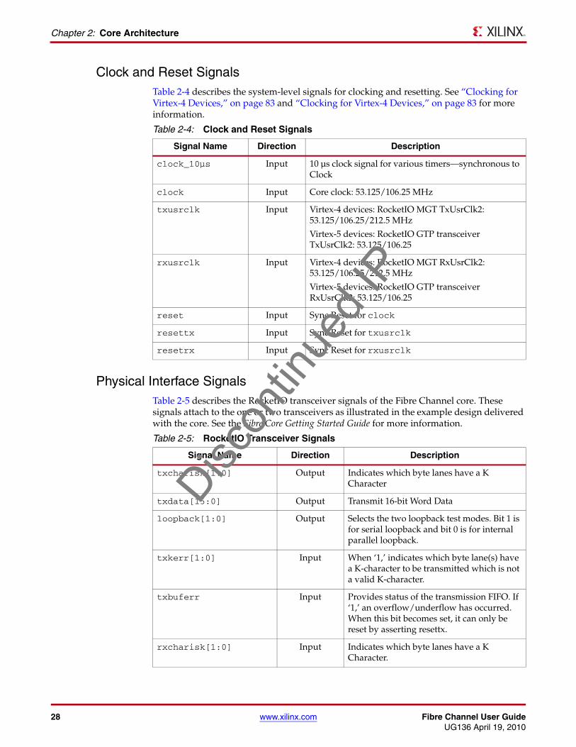
Clock and Reset SignalsTable 2-4 describes the system-level signals for clocking and resetting. See “Clocking for Virtex-4 Devices,” on page 83 and “Clocking for Virtex-4 Devices,” on page 83 for more information.
Physical Interface SignalsTable 2-5 describes the RocketIO transceiver signals of the Fibre Channel core. These signals attach to the one or two transceivers as illustrated in the example design delivered with the core. See the Fibre Core Getting Started Guide for more information.
Table 2-4: Clock and Reset Signals
Signal Name Direction Description
clock_10µs Input 10 µs clock signal for various timers—synchronous to Clock
clock Input Core clock: 53.125/106.25 MHz
txusrclk Input Virtex-4 devices: RocketIO MGT TxUsrClk2: 53.125/106.25/212.5 MHz
Virtex-5 devices: RocketIO GTP transceiver TxUsrClk2: 53.125/106.25
rxusrclk Input Virtex-4 devices: RocketIO MGT RxUsrClk2: 53.125/106.25/212.5 MHz
Virtex-5 devices: RocketIO GTP transceiver RxUsrClk2: 53.125/106.25
reset Input Sync Reset for clock
resettx Input Sync Reset for txusrclk
resetrx Input Sync Reset for rxusrclk
Table 2-5: RocketIO Transceiver Signals
Signal Name Direction Description
txcharisk[1:0] Output Indicates which byte lanes have a K Character
txdata[15:0] Output Transmit 16-bit Word Data
loopback[1:0] Output Selects the two loopback test modes. Bit 1 is for serial loopback and bit 0 is for internal parallel loopback.
txkerr[1:0] Input When ‘1,’ indicates which byte lane(s) have a K-character to be transmitted which is not a valid K-character.
txbuferr Input Provides status of the transmission FIFO. If ‘1,’ an overflow/underflow has occurred. When this bit becomes set, it can only be reset by asserting resettx.
rxcharisk[1:0] Input Indicates which byte lanes have a K Character.
Discon
tinue
d IP

Fibre Channel User Guide www.xilinx.com 29UG136 April 19, 2010
Core Interfaces
rxdata[15:0] Input Receive 16-bit Word Data
rxchariscomma[1:0] Input Similar to rxcharisk except that the data is a comma.
rxcheckingcrc Input CRC status for the receiver. When ‘1’, indicates that the receiver has recognized the end of a data packet.
rxcrcerr Input When ‘1,’ indicates if the CRC code is incorrect.
rxdisperr[1:0] Input Indicates whether a disparity error has occurred on the serial line. Included in byte-mapping scheme.
rxlossofsync[1:0] Input Indicates the state of the LOS FSM:
Bit 1 = Loss of sync (high)
Bit 0 = Resync state (high)
rxnotintable[1:0] Input Status of encoded data: indicates which byte lane(s) contains an invalid character when ‘1.’
rxrealign Input Signal from the MGT denoting that the byte alignment with the serial data stream changed due to a comma detection. Asserted high when re-alignment occurs.
Table 2-5: RocketIO Transceiver Signals (Continued)
Signal Name Direction Description
Discon
tinue
d IP

30 www.xilinx.com Fibre Channel User GuideUG136 April 19, 2010
Chapter 2: Core Architecture
Optics Control and Status SignalsTable 2-6 describes the physical media interface of the Fibre Channel core. These signals are typically connected to an external optical module. See “Accessing Optical Registers Through the Management Interface,” on page 57 for more information.
Table 2-6: Physical Media Interface Signals
Signal Name Direction Description
mod_def_0_p Input Module Definition 0: Indicates module is present when ‘0.’ External I/O Pad.
rx_los_p Input Loss of Signal. External I/O Pad.
tx_fault_p Input Indicates the optical interface has a transmit fault. External I/O Pad.
mod_def_1_p Output Module Definition 1: Serial Clock. External I/O Pad.
tx_disable_p Output Disables the transmit laser when active. External I/O Pad.
moddef_2_in1 Input Module Definition 2: Serial Data In.
moddef_2_en1
1. A tristate buffer is provided in the example design to create the single MOD_DEF_2 signal required.
Output Module Definition 2: Serial Data Out Tri-state Enable.
moddef_2_out1 Output Module Definition 2: Serial Data Out.
Discon
tinue
d IP

Fibre Channel User Guide www.xilinx.com 31UG136 April 19, 2010
Chapter 3
Generating the Core
This chapter provides information about configuring and generating the core using the Xilinx CORE Generator™ tool.
Graphical User InterfaceFigure 3-1 shows the Fibre Channel core Graphical User Interface (GUI) screen.
Component NameBase name of the output files generated for the core. Names must begin with a letter and must be composed from the following characters: a to z, 0 to 9 and “_” (underscore).
X-Ref Target - Figure 3-1
Figure 3-1: Fibre Channel GUI Screen
Discon
tinue
d IP

32 www.xilinx.com Fibre Channel User GuideUG136 April 19, 2010
Chapter 3: Generating the Core
Management InterfaceSelect this option to include the Management Interface. If this option is not selected, the core is generated with a configuration vector. The configuration status is available whether or not this option is selected. Management Interface is selected by default.
Statistics GatheringSelect this option to include the Statistics Gathering. This option is only available if the core includes the optional Management Interface. The statistics vectors are available whether or not the option is selected. Statistics Gathering is not selected by default.
Operation SpeedThe core can be generated to run at different speeds at the serial interface. If one of the multi-speed configurations is selected, the core can run at both 1 and 2 Gbps or 2 and 4 Gbps by the selection of a configuration bit. With the use of the Speed Negotiation block, external logic or software, a speed negotiation algorithm can be performed to switch between these speeds. The other options are 4 Gbps for 4 Gbps operation only, 2 Gbps for 2 Gbps operation only, and 1 Gbps for 1 Gbps operation only. 1 Gbps is the default.
BB Credit ManagementSelect this option to include the Credit Management block. If this option is not selected, the core will not include any credit management. BB Credit Management is selected by default.
Speed NegotiationSelect this option to include the Speed Negotiation block. This block performs speed negotiation as per the FC-FS Section 28 algorithm. This option is only available for multi-speed configurations of the core. Speed Negotiation is not selected by default.
Discon
tinue
d IP

Fibre Channel User Guide www.xilinx.com 33UG136 April 19, 2010
Parameter Values in the XCO File
Parameter Values in the XCO FileXCO file parameter names and their values are identical to the names and values shown in the GUI, except that underscore characters (_) are used instead of spaces. The text in an XCO file is case-insensitive.
Table 3-1 defines the XCO file parameters and values and summarizes the GUI defaults. The following is an example of the CSET parameters in an XCO file:
CSET component_name = myfccore1CSET management_interface = trueCSET statistics_gathering = trueCSET operation_speed = 1GbpsCSET bbcreditmngmt = trueCSET speed_neg = false
Output GenerationThe output files generated from the CORE Generator software are placed in the project directory. The list of output files includes the following:
• The netlist file
• Supporting CORE Generator software files
• Release notes and other documentation
• Subdirectories containing example wrapper files
• Scripts to run the core through the back-end tools and to simulate the core using Mentor Graphics ModelSim
See the Fibre Channel Getting Started Guide for definitions of all output files.
Table 3-1: XCO File Values and Default Values
Parameter XCO File Values Default Setting
component_name ASCII text starting with a letter and based on the following character set: a..z, 0..9 and _
fibre_channel_v3_5
management_interface One of the following keywords: true, false
true
statistics_gathering One of the following keywords: true, false
false
operation_speed One of the following values: 1 Gbps, 2 Gbps, 4 Gbps Multispeed, Multispeed2_4
1 Gbps
bbcreditmngmt One of the following keywords: true, false
true
speed_neg One of the following keywords: true, false
false
Discon
tinue
d IP

34 www.xilinx.com Fibre Channel User GuideUG136 April 19, 2010
Chapter 3: Generating the Core
Discon
tinue
d IP

Fibre Channel User Guide www.xilinx.com 35UG136 April 19, 2010
Chapter 4
Designing with the Core
This chapter provides general guidelines for creating designs using the Fibre Channel core, including a detailed description of each interface to the core. For information about special design considerations (for example, clocking schemes and startup sequences), see Chapter 6, “Design Considerations.”
To work with the example design included with the Fibre Channel core, see the Fibre Channel Getting Started Guide.
Design GuidelinesThis section defines the steps required to design a fully-functioning design integrated with user application logic for a variety of implementations. Not all designs require all the design steps. For best results and maximum performance, adhere to the design guidelines in this manual.
Design StepsGenerate the core from the Xilinx CORE Generator™ software. See Chapter 3, “Generating the Core.”
Using the HDL Wrapper as User Top-level
See “Wrapper Files,” page 91 and the Fibre Channel Getting Started Guide for more information.
• Edit the HDL wrapper file produced by the CORE Generator software to add user logic and any other I/Os required. Remove I/O Buffers (IOBs) no longer required. Add/change clocking scheme.
• Synthesize the entire design. The Xilinx Synthesis Tool (XST) script and project file in the /implement directory may be adapted to include your HDL files.
• Run the implement script in the /implement directory to create a top-level netlist, which includes the Fibre Channel core netlist. The script may also run the Xilinx tools map, par and bitgen, creating a bitstream that can be downloaded to a Xilinx device.
• Simulate the entire design in ModelSim or Cadence IES.
• Download the bitstream to a Virtex®-4 or Virtex-5 device.
Discon
tinue
d IP

36 www.xilinx.com Fibre Channel User GuideUG136 April 19, 2010
Chapter 4: Designing with the Core
Using the HDL Wrapper in a User Design
See “Wrapper Files,” page 91 and the Fibre Channel Getting Started Guide for more information.
• Edit the HDL wrapper file produced by the CORE Generator software to remove unnecessary IOBs, pipeline registers, Digital Clock Managers (DCMs), and anything else not required by you. These may need to be replicated within your top-level design.
• Add an interface to the HDL wrapper so that it may be instanced in your design.
• Synthesize the entire design, including the same files used for default implementation.
• Run the Xilinx tools map, par, and bitgen to create a bitstream that can be downloaded to a Xilinx device. Care must be taken to constrain the design correctly, and the UCF produced by the CORE Generator software should be used as the basis for your UCF. See Chapter 5, “Constraining the Core” for additional information.
• Simulate the entire design in ModelSim.
• Download the bitstream to a Virtex-4 or Virtex-5 device.
Note: Sections within the wrapper labeled DO NOT MODIFY indicate where modifications could break the example design.
Understand Signal PipeliningPipeline registers are used in the example design provided with the core only to allow the core interfaces to be interfaced cleanly to the IOBs on the selected device; these registers create artificial latency on some inputs and outputs in the wrapper file. Because a user design will most likely connect to the core interfaces on the same FPGA fabric, the pipeline registers will probably not be required in a user design and can be safely removed if you plan to add interface registers to their own logic.
Register All I/OsTo simplify timing and increase system performance in an FPGA design, register all I/Os. All inputs and outputs from your application should come from, or connect to, a flip-flop inside your application. It may not be possible to register the signal on all paths; however, doing so simplifies timing analysis and makes it easier for the Xilinx tools to place and route the design.
Recognize Timing Critical SignalsThe known timing-critical signals in the Fibre Channel core are in the optional Statistics Gathering block. The UCF provided with the core identifies these signals and the timing constraint that should be applied.
Use Supported Design FlowsCurrently, the XST/ISE® software v12.1/ModelSim and the XST/ISE software v12.1/Cadence IES design flows are supported for the Fibre Channel core.
Discon
tinue
d IP

Fibre Channel User Guide www.xilinx.com 37UG136 April 19, 2010
System Signals
Make Only Allowed ModificationsFibre Channel core interfaces cannot be user-modified. With the exception of example design files, all modifications to the core must be completed when the core is generated.
Note: Sections within the example design labeled DO NOT MODIFY indicate where modifications could break the example design.
System Signals
Example Design IssuesAll ports of the core, with the exception of the RocketIO™ transceiver serial ports and module definition ports, are intended to be internal connections in the FPGA fabric. An example HDL wrapper is delivered with the core which adds IBUFs, OBUFs, and I/O registers where appropriate to the appropriate external signals (such as clocks and resets). IOBs and pipeline registers are also added to the remaining unconnected ports to allow the design example to be downloaded to a Virtex-4 or Virtex-5 device. See “Wrapper Files,” page 91 for more information.
Interface SignalsSee “Core Interfaces” in Chapter 2 for complete information about the various interface signals for the Fibre Channel core.
Setting up the Core
Resetting the CoreAfter the core is powered-up, all reset signals should be asserted for at least 200 ns. An example is provided in the HDL wrapper file of how to generate all reset signals such that any clocking circuitry is frequency-locked before they are deasserted. Extra time should be allowed for the transceivers to lock after reset.
Enabling the CoreAfter the core is reset, it is necessary to set some register/configuration bits before the core will function. See “Startup Sequencing,” page 92 and “Accessing Configuration Space Registers,” page 47 for details.
Do the following:
1. Enable the PHY by setting the Transmit Disable bit to ‘0’ in the OpticsControl register.
1. Set the speed for the transceivers and enable them by setting the appropriate register bits in the LinkControl register.
2. Negotiate speeds (multi-speed core only). See “Startup Sequencing,” page 92 and “Performing Speed Negotiation,” page 75 for details.
3. Enable the Port State Machine (PSM) by setting the appropriate bit in the PSMControl register.
At this point the core attempts to initialize the link following the FC-PH standard (Old Port State Machine).
Discon
tinue
d IP
38 www.xilinx.com Fibre Channel User GuideUG136 April 19, 2010
Chapter 4: Designing with the Core
4. Wait for Active state.
If link initialization was successful, the core enters the active state and begins transmitting fill words and any valid FC-FS frames presented on its Client Transmit Interface. It is now also able to receive frames.
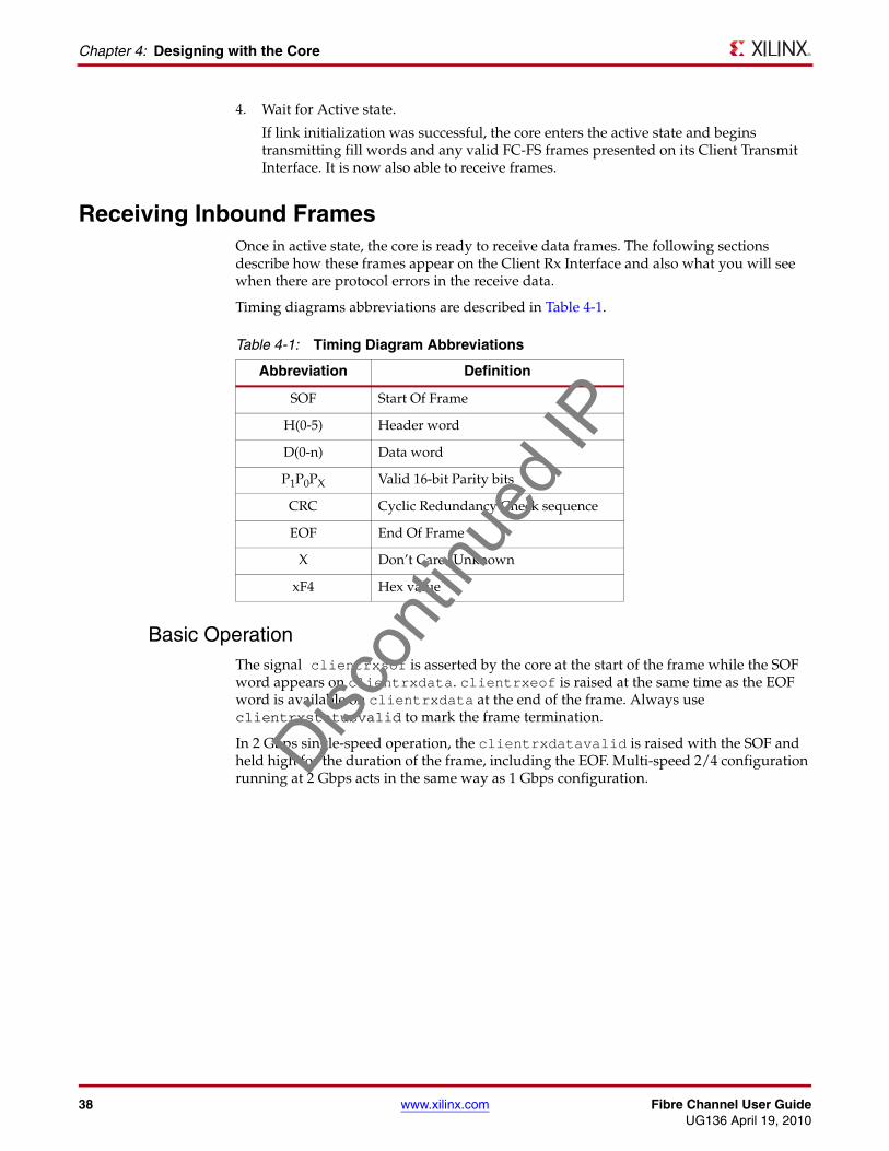
Receiving Inbound FramesOnce in active state, the core is ready to receive data frames. The following sections describe how these frames appear on the Client Rx Interface and also what you will see when there are protocol errors in the receive data.
Timing diagrams abbreviations are described in Table 4-1.
Basic OperationThe signal clientrxsof is asserted by the core at the start of the frame while the SOF word appears on clientrxdata. clientrxeof is raised at the same time as the EOF word is available on clientrxdata at the end of the frame. Always use clientrxstatusvalid to mark the frame termination.
In 2 Gbps single-speed operation, the clientrxdatavalid is raised with the SOF and held high for the duration of the frame, including the EOF. Multi-speed 2/4 configuration running at 2 Gbps acts in the same way as 1 Gbps configuration.
Table 4-1: Timing Diagram Abbreviations
Abbreviation Definition
SOF Start Of Frame
H(0-5) Header word
D(0-n) Data word
P1P0PX Valid 16-bit Parity bits
CRC Cyclic Redundancy Check sequence
EOF End Of Frame
X Don’t Care/Unknown
xF4 Hex value
Discon
tinue
d IP

Fibre Channel User Guide www.xilinx.com 39UG136 April 19, 2010
Receiving Inbound Frames
The timing of a normal 2/4 Gbps frame reception across the Client Interface is shown in Figure 4-1.
The core performs some analysis on the frame as it is being received and provides information on the frame to the client via the clientrxstatus vector. The definition of this vector is described in Table 4-2.
This vector is validated by the clientrxstatusvalid signal. clientrxstatusvalid also indicates the termination of the frame even when the EOF is missing (see Figure 4-3, Figure 4-4, and Figure 4-5).
clientrxframevalid is asserted high with clientrxsof and stays high until clientrxstatusvalid has been asserted and indicates the framing of the received frame.
Whether or not parity checking on the transmit path is disabled, the core provides parity information with each word of Rx data. There are two parity bits; the least significant bit relates to the parity of the least significant 16-bits in clientrxdata and the most significant bit relates to the parity of the most significant 16-bits in clientrxdata. An example of the use of parity is shown in Figure 4-1. The use of parity is not shown in further timing diagrams.
X-Ref Target - Figure 4-1
Figure 4-1: Normal 2 Gbps Frame Reception across Client Interface
Table 4-2: ClientRxStatus Definition
ClientRxStatus Description
Bit 0 CRC Error
Bit 1 Illegal Transmission Word
Bit 2 Undersized Frame Error
Bit 3 Oversized Frame Error
Bit 4 Invalid EOF
Bit 5 Frame received while not in Active State
Clock
ClientRxData[31:0]
ClientRxDataValid
ClientRxSOF
ClientRxEOF
ClientRxFrameValid
ClientRxStatus[5:0]
ClientRxStatusValid
SOF H0 H1 H2 H3 H4 H5 D0 Dn CRC EOF
x00
ClientRxParity[1:0] P1P0 P1P0P1P0 P1P0P1P0P1P0P1P0P1P0 P1P0 P1P0 P1P0
Discon
tinue
d IP

40 www.xilinx.com Fibre Channel User GuideUG136 April 19, 2010
Chapter 4: Designing with the Core
The timing of a normal 1 Gbps and multi-speed 2/4 running at 2 Gbps frame reception across the Client Interface is shown in Figure 4-2. The signal clientrxdatavalid changes every clock cycle, and clientrxdata changes every other clock cycle. The other control signals align with the data. This is the only difference between 1 Gbps operation and single-speed 2 or 4 Gbps operation.
All timing diagrams from this point forward display 2 Gbps operations, from which 1 and 4 Gbps operations can be inferred. Despite the change in horizontal scale, this is the same clock as Figure 4-1.
Abnormal Frame ReceptionUnder normal circumstances, the clientrxstatusvalid will rise coincidentally with clientrxeof to mark the end of the frame. However, there are a number of situations where this operation will differ.
Maximum Frame Length Exceeded
If the maximum frame length is exceeded on reception, clientrxstatusvalid will be asserted, and clientrxstatus will identify the error in the frame even though this may not be coincident with clientrxeof. Data will continue to be passed to the client until the EOF appears, but clientrxframevalid will remain low. This condition is shown in Figure 4-3.
X-Ref Target - Figure 4-2
Figure 4-2: Normal 1 Gbps Frame Reception Across Client Interface
Clock
ClientRxData[31:0]
ClientRxDataValid
ClientRxSOF
ClientRxEOF
ClientRxFrameValid
ClientRxStatus[5:0]
ClientRxStatusValid
SOF H0 H1 H2 H3 H4 H5 D0 Dn CRC EOF
x00
Discon
tinue
d IP

Fibre Channel User Guide www.xilinx.com 41UG136 April 19, 2010
Receiving Inbound Frames
X-Ref Target - Figure 4-3
Non-Data Word Received
If a non-data word is received during a frame reception, this invalidates the frame. The core will raise clientrxstatusvalid at this point and indicate the error in clientrxstatus. An example of this situation with an invalid character received instead of H3 is shown in Figure 4-4.
Missing EOF
If a frame is received without an EOF, then clientrxstatusvalid is raised after the last data word with clientrxstatus indicating the error to the client. If the EOF is missing and the interframe gap (IFG) words have also been removed, clientrxstatusvalid may be raised at the same time as new clientrxsof, or before, to terminate the previous frame with an error and still allow this new frame to be received correctly. In this situation, clientrxframevalid will remain high between the two frames. Figure 4-5 shows an example of this condition.
Figure 4-3: Abnormal 2 Gbps Frame Reception Across Client Interface with Maximum Frame Length Exceeded
Clock
ClientRxData[31:0]
ClientRxDataValid
ClientRxSOF
ClientRxEOF
ClientRxFrameValid
ClientRxStatus[5:0]
ClientRxStatusValid
SOF H0 H1 H2 H3 H4 H5 D0 D527 D528 D529D530 CRC EOF
x08
X-Ref Target - Figure 4-4
Figure 4-4: Abnormal 2 Gbps Frame Reception Across Client Interface with Non-Data Word
Clock
ClientRxData[31:0]
ClientRxDataValid
ClientRxSOF
ClientRxEOF
ClientRxFrameValid
ClientRxStatus[5:0]
ClientRxStatusValid
SOF H0 H1 H2 H4 H5 D0 Dn CRC EOFXX
x02Discon
tinue
d IP

42 www.xilinx.com Fibre Channel User GuideUG136 April 19, 2010
Chapter 4: Designing with the Core
X-Ref Target - Figure 4-5
Back-to-Back Frame ReceptionWhile the Fibre Channel standard specifies the minimum interframe gap (IFG) at the receiver will be no less than 2 words after clock correction, the Fibre Channel core is capable of receiving frames with no IFG. clientrxframevalid will not fall between the frames, but clientrxstatusvalid may be used to identify the EOF of each frame and thus safely delineate the frames in your logic.
Figure 4-5: Abnormal 2 Gbps Frame Reception Across Client Interface with Missing EOF and IFG
Clock
ClientRxData[31:0]
ClientRxDataValid
ClientRxSOF
ClientRxEOF
ClientRxFrameValid
ClientRxStatus[5:0]
ClientRxStatusValid
SOF H0 H1 H2 H3 H4 H5 D0 Dn CRC SOF H0 H1 H2 H3
x10
X-Ref Target - Figure 4-6
Figure 4-6: Reception of Back-to-Back Frames
Clock
ClientRxData[31:0]
ClientRxDataValid
ClientRxSOF
ClientRxEOF
ClientRxFrameValid
ClientRxStatus[5:0]
ClientRxStatusValid
SOF H0 H1 H2 H3 H4 H5 D0 Dn CRC EOF SOF H0 H1 H2
x00Discon
tinue
d IP
Fibre Channel User Guide www.xilinx.com 43UG136 April 19, 2010
Transmitting Outbound Frames
Transmitting Outbound Frames
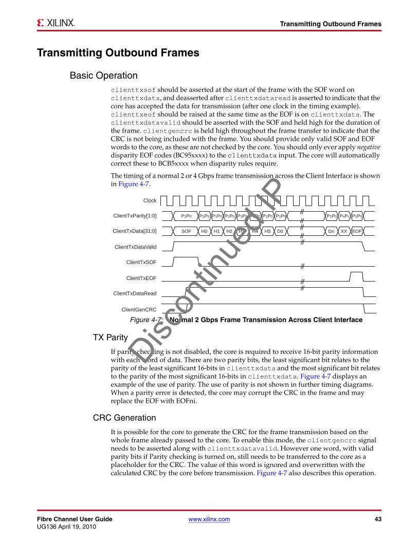
Basic Operationclienttxsof should be asserted at the start of the frame with the SOF word on clienttxdata, and deasserted after clienttxdataread is asserted to indicate that the core has accepted the data for transmission (after one clock in the timing example). clienttxeof should be raised at the same time as the EOF is on clienttxdata. The clienttxdatavalid should be asserted with the SOF and held high for the duration of the frame. clientgencrc is held high throughout the frame transfer to indicate that the CRC is not being included with the frame. You should provide only valid SOF and EOF words to the core, as these are not checked by the core. You should only ever apply negative disparity EOF codes (BC95xxxx) to the clienttxdata input. The core will automatically correct these to BCB5xxxx when disparity rules require.
The timing of a normal 2 or 4 Gbps frame transmission across the Client Interface is shown in Figure 4-7.
TX Parity
If parity checking is not disabled, the core is required to receive 16-bit parity information with each word of data. There are two parity bits, the least significant bit relates to the parity of the least significant 16-bits in clienttxdata and the most significant bit relates to the parity of the most significant 16-bits in clienttxdata. Figure 4-7 displays an example of the use of parity. The use of parity is not shown in further timing diagrams. When a parity error is detected, the core may corrupt the CRC in the frame and may replace the EOF with EOFni.
CRC Generation
It is possible for the core to generate the CRC for the frame transmission based on the whole frame already passed to the core. To enable this mode, the clientgencrc signal needs to be asserted along with clienttxdatavalid. However one word, with valid parity bits if Parity checking is turned on, still needs to be transferred to the core as a placeholder for the CRC. The value of this word is ignored and overwritten with the calculated CRC by the core before transmission. Figure 4-7 also describes this operation.
X-Ref Target - Figure 4-7
Figure 4-7: Normal 2 Gbps Frame Transmission Across Client Interface
Clock
ClientTxData[31:0]
ClientTxDataValid
ClientTxSOF
ClientTxEOF
ClientTxDataRead
ClientGenCRC
SOF H0 H1 H2 H3 H4 H5 D0 Dn XX EOF
ClientTxParity[1:0] P1P0 P1P0 P1P0 P1P0 P1P0 P1P0 P1P0 P1P0 P1P0 PxPx P1P0
Discon
tinue
d IP

44 www.xilinx.com Fibre Channel User GuideUG136 April 19, 2010
Chapter 4: Designing with the Core
TX Speed Considerations
The timing of a 1 Gbps or multi-speed 2/4 configuration running at 2 Gbps frame transmission across the Client Interface is shown in Figure 4-8. Note how new data is accepted every other clock by the clienttxdataread signal toggling every clock tick. This results in half the transfer rate compared to the single-speed 2 and 4 Gbps mode respectively.X-Ref Target - Figure 4-8
The only difference between the 1 Gbps or multi-speed 2/4 configuration running at 2 Gbps timing diagrams and the 2 or 4 Gbps timing diagrams is this oscillation of clienttxdataread. Therefore, all further timing diagrams will be based on single-speed 2 Gbps operation, and the 1 Gbps or multi-speed 2/4 configuration running at 2 Gbps timings can be inferred.
Discontinue a Frame Transmission
Client Underflow
It is expected that the Client Interface will connect to a FIFO. When a frame transmission, it is important that the whole frame is transferred to the FC core uninterrupted. If the FIFO underflows, it can advise the core of this fact by taking clienttxdatavalid low until it has new data to send.
As the core does not buffer a frame internally, the frame may already be transferring across the physical interface. The core ends the frame at this point by transmitting an EOFa. It will continue reading data from the FIFO, but this data will be discarded. After a new clienttxsof is transferred to the core, a new frame transmission begins. An abnormal frame transmission is shown in Figure 4-9 with a delay in new data after Header word, H2, for one clock cycle. This frame will be invalidated by the core and it will be up to your design to schedule retransmission.
Figure 4-8: Normal 1 Gbps Frame Transmission Across Client Interface
Clock
ClientTxData[31:0]
ClientTxDataValid
ClientTxSOF
ClientTxEOF
ClientGenCRC
ClientTxDataRead
SOF H0 H1 H2 H3 H4 H5 D0 Dn CRC EOF
Discon
tinue
d IP

Fibre Channel User Guide www.xilinx.com 45UG136 April 19, 2010
Transmitting Outbound Frames
Flow-control on the Data PathAs defined by the Fibre Channel standards, no frames may be transmitted when there is no outstanding Credit at the far-end port. The core supports Buffer-to-Buffer Credit (BBCredit) with a default Outstanding Credit value of one. The Credit Management block in the core is responsible for monitoring the level of BBCredit remaining to the far-end port and throttling back the Transmit Data accordingly. Figure 4-10 shows the transmit path being held up until reception of a r_rdy primitive from the far-end port. If the Credit block is omitted, the core will transmit frames as requested without waiting for r_rdy primitives.
Throttling Credit PrimitivesAs part of Credit Management, it may be necessary to delay the transmission of R_RDY primitives by the Credit Management block in the core: for example, when your design has only as many frame buffers remaining unused as it advertised BBCredit for during Port Initialization. See “Using BBCredit,” page 72 for more information.
When the Credit Management is included with the core, the signal applybackpressure is provided for this reason. If applybackpressure is asserted, no r_rdy primitives are returned to the far end Fibre Channel port. These credits are queued for transmission as soon as possible after applybackpressure is deasserted. When r_rdys are pending transmission and applybackpressure has been held high, pulling applybackpressure low for a single core clock tick will allow a single r_rdy to be transmitted during the next interframe gap (IFG). One pending r_rdy will be transmitted for each clock cycle that applybackpressure is held low before the following IFG.
X-Ref Target - Figure 4-9
Figure 4-9: Underrun 2 Gbps Frame Transmission Across Client Interface
Clock
ClientTxData[31:0]
ClientTxDataValid
ClientTxSOF
ClientTxEOF
ClientTxDataRead
ClientGenCRC
SOF H0 H1 H2 H3 H4 H5 D0 Dn CRC EOF
X-Ref Target - Figure 4-10
Figure 4-10: Delay Transmission Until Reception of R_RDY BBCredit Primitive
ClientRxData[31:0]
ClientTxSOF
ClientTxDataRead
Frame R1 Frame R2
ClientTxData[31:0] Rest of Frame T1 Rest of Frame T2
R_RDY
>> IFGmin
SOF
SOF
Discon
tinue
d IP

46 www.xilinx.com Fibre Channel User GuideUG136 April 19, 2010
Chapter 4: Designing with the Core
Figure 4-11 shows how two R_RDY primitives are transmitted in the IFG after applybackpressure is deasserted, but none in the IFG before that.
Back-to-Back Frame TransmissionTransmission of back-to-back frames requires that the core inserts the minimum IFG of six words between each frame. Hence there is a given minimum IFG on the Client Tx Interface. The core will not accept any transmit data during the IFG. Figure 4-12 shows transmission delay between two transmit frames.
X-Ref Target - Figure 4-11
Figure 4-11: Effect of ApplyBackPressure on Transmission of R_RDY Primitives
ClientRxData[31:0]
ClientTxSOF
ClientTxDataRead
Frame R1 Frame R2 R3
ClientTxData[31:0] Frame T1 Frame T2 T3
AplyBackPressure
Serial Tx Data Frame T1 Frame T2 T3
2 x IDLER_RDY
2 x IDLER_RDY
2 x IDLE
6 x IDLE
X-Ref Target - Figure 4-12
Figure 4-12: Back-to-Back Transmission of Frames
Clock
ClientTxData[31:0]
ClientTxDataValid
ClientTxSOF
ClientTxEOF
ClientTxDataRead
SOF H0 H1 H2 H3 H4 H5 D0 Dn CRC EOF H0SOF
Discon
tinue
d IP

Fibre Channel User Guide www.xilinx.com 47UG136 April 19, 2010
Accessing Configuration Space Registers
Automatic Responses by the CoreAs mentioned in previous sections, the optional Credit Management block in the core is responsible for automatically generating R_RDY primitives for transmission under control of the applybackpressure signal. The Credit Management block will also generate BB_SCr and BB_SCs primitives as required to support the bb_sc_n credit recovery mechanism defined in FC-FS v1.9 Section 18.5.11. When the Credit Management block detects missing SOFs on the receive path, it will automatically generate the correct number of r_rdy primitives to recover the missing credit and queue these up for transmission.
The core is also responsible for inserting EOFa words when a transmission underrun is detected. This will happen as soon as the Underrun is detected and the rest of the current transmit frame will be discarded.
If Parity checking is enabled on the transmit path (see “Accessing Configuration Space Registers,” page 47) and EOFni-insertion is not disabled, the EOF of the current frame is automatically replaced by EOFni to invalidate the frame when a parity error is detected on the transmit data. If EOFni-insertion is disabled, the core will take no action other than to log the parity error in the statistics gathering block (if that is available).
Accessing Configuration Space RegistersThese registers are only available for cores which have been generated to include the Management Interface. See the following section for information on how to use the core when no Management Interface is available.
Registers Mapped Directly onto the Configuration SpaceOnce the core is powered up and reset, the client can reconfigure some of the core parameters from their default values. Configuration changes can be written at any time, however some configurations will not take effect immediately and may wait until the core is in a particular state. This is indicated for the specific bits where appropriate.
Configuration of the core is performed through a 32-bit wide register bank accessed through the Management Interface. The configuration registers available in the core are detailed in Table 4-3.
Table 4-3: Configuration Registers
Address Description
0x000 OpticsControl
0x004 OpticsStatus
0x008 ModDefAddress
0x00C ModDefData
0x010 LinkControl
0x014 LinkStatus
0X020 PSMControl
0X024 PSMStatus
0X028 HostPrimData
Discon
tinue
d IP

48 www.xilinx.com Fibre Channel User GuideUG136 April 19, 2010
Chapter 4: Designing with the Core
Register MapsThe register contents for the configuration registers are described in the following tables. All register bits are read-writable unless otherwise identified.
0X02C TOV
0X030 B2BCredit
0X034 OutStdB2BCredit
0X038 OutStdRRDYCredit
0X03C BB_SC_N
0X040 BB_SCs
0X044 BB_SCr
Table 4-3: Configuration Registers (Continued)
Address Description
Table 4-4: OpticsControl (0x000)
Bit Default Value Description
31-1 N/A Reserved
0 1 Transmit Disable: Disables the transmit laser when active (high).
Discon
tinue
d IP

Fibre Channel User Guide www.xilinx.com 49UG136 April 19, 2010
Accessing Configuration Space Registers
Table 4-5: OpticsStatus (0x004)
Bit Default Value Description
31-17 N/A Reserved
16 N/A Loss of Signal: Indicates loss of signal at the optical receiver when active (high) as reported by the optics device. This signal will be active when the received optical power is below the worst-case receiver sensitivity. This bit is read-only as it represents the state of the input signal RX_LOS_P.
15-2 N/A Reserved
1 N/A Module Not Present: Indicates that an optical transceiver is not present when active (high). This signal is used for Small Form-factor Pluggable (SFP) applications so that the system can determine whether or not a transceiver is installed. For fixed optical applications, this signal should be tied low (inactive). This bit is read-only as it represents the state of the input signal MOD_DEF_0_P.
0 N/A Transmit Fault: Indicates a transmit laser fault when active (high) as reported by the optics device. This bit is read-only as it represents the state of the input signal TX_FAULT_P.
Table 4-6: ModDefAddress (0x008)
Bit Default Value Description
31-20 N/A Reserved
19 N/A Error: This bit is set if an error was detected on the ModDef interface during the last read or write cycle. This bit is read-only as it depends on the ModDef interface.
18 0 Reset: Setting this bit causes a reset sequence to be sent on the ModDef interface.
17 N/A Busy: This bit determines whether the EEPROM is ready to be accessed. The bit also specifies whether or not the data byte in the ModDefData register is available to be read. This bit is read-only as it depends on the ModDef interface.
16 0 Read: This bit determines whether the EEPROM will be written (low) or read (high).
15-11 N/A Reserved
10-0 0x000 Address: This is the byte address value passed to the EEPROM located in the SFP.
Discon
tinue
d IP

50 www.xilinx.com Fibre Channel User GuideUG136 April 19, 2010
Chapter 4: Designing with the Core
Table 4-7: ModDefData (0x00C)
Bit Default Value Description
31-8 N/A Reserved
7-0 0x00 Data: Data byte read from or to be written to the EEPROM.
Table 4-8: LinkControl (0x010)
Bit Default Value Description
31-30 N/A Reserved
29 0 IFG Adjust: Enables custom IFG parameters in place of default settings when set active (high). When inactive, custom parameters have no effect.
28-25 0x0 Frame to Frame IFG: Custom minimum separation between Frames. Enabled by bit 29. Actual value will be one more than value specified here.
24-21 0x0 Frame to R_RDY IFG: Custom minimum separation of R_RDY primitives. Applies both before and after the R_RDY. Enabled by bit 29. Actual value will be one more than value specified here.
20 1 Receive MGT Disable: Disables the operation of the receive channel within the MGT.
19 0 Serial Loopback: Selects the serial loopback path to the receiver when set.
18 0 Parallel Loopback: Selects the parallel loopback path to the receiver when set.
17 N/A Reserved
17-16 0x1[1] Receive Speed: Selects the receive serial data baud: 0x0 = slower data rate, 0x1 = faster data rate. Bit 17 is not used in this version of the core. These bits are read-only for the fixed speed version of the core and indicate the correct speed of operation.
15-5 N/A Reserved
4 1 Transmit MGT Disable: Disables the operation of the transmit channel within the MGT.
3 1 Parity Disable: Disables the automatic corruption of the CRC for frames in which a parity error has been detected in the transmit channel.
Discon
tinue
d IP

Fibre Channel User Guide www.xilinx.com 51UG136 April 19, 2010
Accessing Configuration Space Registers
2 0 EOFniDisable: Disables the automatic insertion of the EOFni code when certain error conditions are discovered in the transmit channel.
1-0 0x1[1] Transmit Speed: Selects the transmit serial data baud rate: 0x0 = slower data rate, 0x1 = faster data rate. Bit 1 is not used. These bits are read-only for the fixed speed version of the core and indicate the correct speed of operation.
1. Default only relevant for multi-speed version of the core; for single-speed versions, these bits are read-only and indicate the correct speed of operation.
Table 4-9: LinkStatus (0x014)
Bit Default Value Description
31-22 N/A Reserved
21-16 N/A Loss of Synchronization Finite State Machine: Loss of Synchronization FSM output vector. This vector indicates the current state of the receive channel synchronization process and is used to ensure that the received bit stream has been decoded correctly. These bits are read-only as they represent the real-time output from the LOS FSM. See Table 4-10.
15-2 N/A Reserved
1 See description Eval: This bit is ‘1’ if the core has been generated with a Full System Evaluation License and is ‘0’ if the core has been generated with a Full License.
0 N/A Transmit Buffer Error: This bit is set when the MGT transmit FIFO has either an overflow or underflow condition. This bit can only be reset by setting the TxMGTDisable bit. This bit is read-only as it represents the real-time output from the MGT FIFO.
Table 4-8: LinkControl (0x010) (Continued)
Bit Default Value Description
Discon
tinue
d IP

52 www.xilinx.com Fibre Channel User GuideUG136 April 19, 2010
Chapter 4: Designing with the Core
LOSFSM state
Table 4-10 shows the mapping of Loss of Synchronization State Machine states to bits in the register described previously. The state machine is described in FC-FS v1.9 Section 6.1.2
Table 4-10: LOS FSM Field Definition
FSM State Bits [21:16]
Reset (C) 100000
Out of Sync (A) 010000
Sync B4 001000
Sync B3 000100
Sync B2 000010
Sync B1 000001
Table 4-11: PSMControl (0x020)
Bit Default Value Description
31-21 N/A Reserved
20 0 PSMNext Valid: Enable the use of the PSMNext field. When clear, the PSMNext field is ignored. The FC core resets this bit once the core has read the PSMNext field.
19-16 0x0 Port State Machine Next: Next state vector.
15-2 N/A Reserved
1 0 Statistics Enable: Enables the collection of FC statistics.
0 0 Enable: Enables the operation of the Port State Machine, when set. Clearing this bit will return the PSM to the offline state OL1.
Table 4-12: PSMStatus (0x024)
Bit Default Value Description
31-20 N/A Reserved
19-16 N/A Port State Machine: Current state vector. This bit is read-only as it represents the state of the port state machine.
15-0 N/A Reserved
Discon
tinue
d IP

Fibre Channel User Guide www.xilinx.com 53UG136 April 19, 2010
Accessing Configuration Space Registers
The PSM Control and Status registers provide both control and status of the Port State Machine respectively. Each time the PSMNext field is written and the PSMNext Valid flag is set, the PSMNext state is forced into the PSM. The PSM and PSMNext fields have two sub-fields; the most significant bits define Major state transitions and the LSBs control the Minor state transitions. Control of this state machine should only be for Major state transitions and the Minor state should be set to a null value (00). This will allow the PSM to transition through the correct Minor state(s) for each Major state transition. Table 4-13 describes the PSM states and their corresponding PSM field bits. The PSM is defined in FC-FS v1.9 Section 7.
Table 4-13: PSM Field Definition
Major State Bits [19:18] Minor State Bits [17:16]
Active 00 N/A 00
Link Reset 01 LR1 01
Link Reset 01 LR2 10
Link Reset 01 LR3 11
Link Failure 10 LF1 01
Link Failure 10 LF2 10
Offline 11 OL1 01
Offline 11 OL2 10
Offline 11 OL3 11
Table 4-14: HostPrimData (0x028)
Bit Default Value Description
31-24 0x00
Primitive Count: Specifies the number of Primitive Data words to be transmitted by the FC core. A count of zero will terminate such transmission and a count of 255 will be a continuous transmission. A count between 0 and 255 will cause the FC core to transmit that exact number of primitives. useful for debug purposes
23 - 0 0x000000
Primitive Data: Specifies the lower 24 bits of the Ordered Set that will be transmitted. The most significant byte of the Ordered Set will be a K28.5 character.
Discon
tinue
d IP
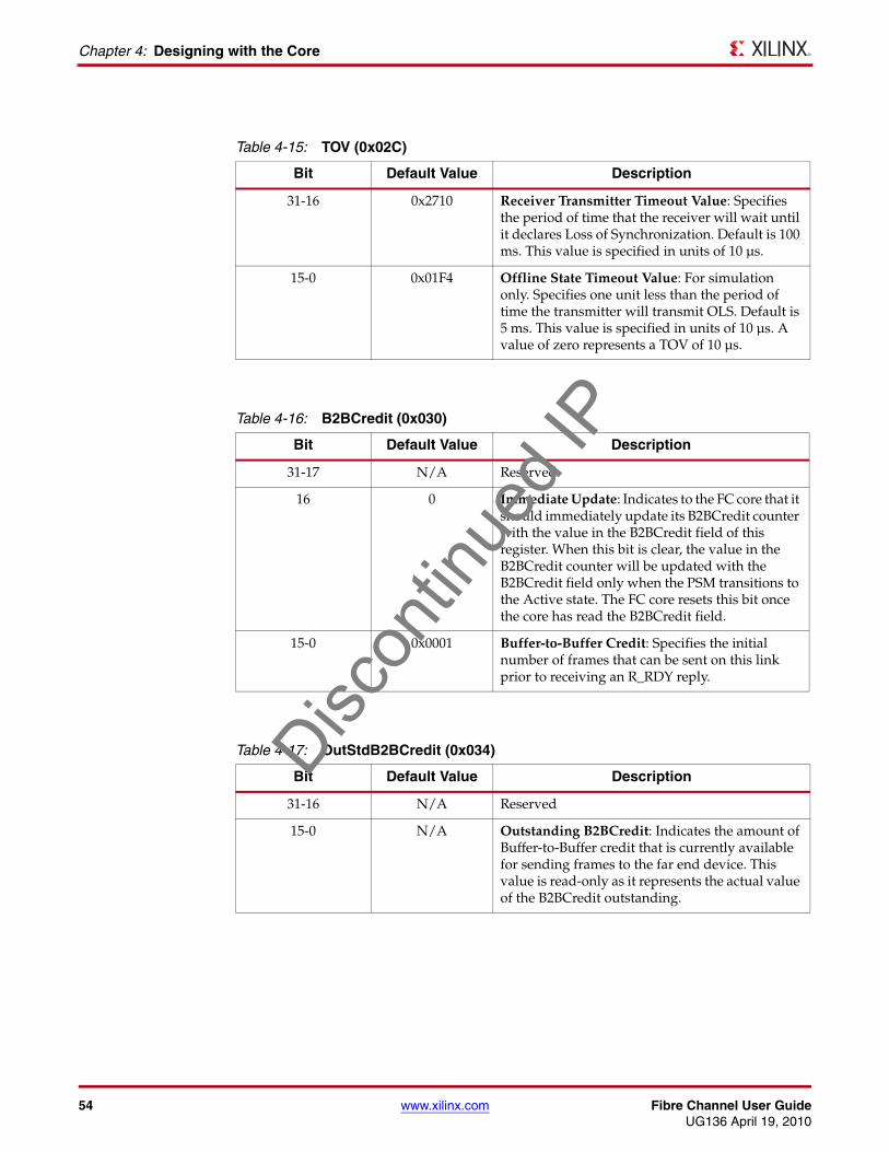
54 www.xilinx.com Fibre Channel User GuideUG136 April 19, 2010
Chapter 4: Designing with the Core
Table 4-15: TOV (0x02C)
Bit Default Value Description
31-16 0x2710 Receiver Transmitter Timeout Value: Specifies the period of time that the receiver will wait until it declares Loss of Synchronization. Default is 100 ms. This value is specified in units of 10 µs.
15-0 0x01F4 Offline State Timeout Value: For simulation only. Specifies one unit less than the period of time the transmitter will transmit OLS. Default is 5 ms. This value is specified in units of 10 µs. A value of zero represents a TOV of 10 µs.
Table 4-16: B2BCredit (0x030)
Bit Default Value Description
31-17 N/A Reserved
16 0 Immediate Update: Indicates to the FC core that it should immediately update its B2BCredit counter with the value in the B2BCredit field of this register. When this bit is clear, the value in the B2BCredit counter will be updated with the B2BCredit field only when the PSM transitions to the Active state. The FC core resets this bit once the core has read the B2BCredit field.
15-0 0x0001 Buffer-to-Buffer Credit: Specifies the initial number of frames that can be sent on this link prior to receiving an R_RDY reply.
Table 4-17: OutStdB2BCredit (0x034)
Bit Default Value Description
31-16 N/A Reserved
15-0 N/A Outstanding B2BCredit: Indicates the amount of Buffer-to-Buffer credit that is currently available for sending frames to the far end device. This value is read-only as it represents the actual value of the B2BCredit outstanding.
Discon
tinue
d IP

Fibre Channel User Guide www.xilinx.com 55UG136 April 19, 2010
Accessing Configuration Space Registers
Table 4-18: OutStdRRDYCredit (0x038)
Bit Default Value Description
31-16 N/A Reserved
15-0 N/A Outstanding R_RDYCredit: Indicates the amount of credit (R_RDYs) that is currently pending for return to the far end device. The R_RDY counter keeps track of how many R_RDY primitives need to be transmitted based on how many frames have been received.
Credit is returned for frames that have a valid SOF and have at least one word of valid data following the SOF, independent of the validity of the CRC. This value is read-only as it represents the actual value of the R_RDYCredit outstanding.
Table 4-19: BB_SC_N (0x03C)
Bit Default Value Description
31-4 N/A Reserved
3-0 0x0 Buffer-to-Buffer State Change Number: Specifies the log2 of the B2B_Credit Recovery Modulus.
Table 4-20: BBSCNFrame (0x040)
Bit Default Value Description
31-16 N/A Received Frames: Indicates the number of frames received since the last BB_SCs was received. This value is read-only as it represents the actual value of Received Frames counter.
15-0 N/A Transmitted Frames: Indicates the number of frames transmitted since the last BB_SCs was sent. This value is read-only as it represents the actual value of Transmitted Frames counter.
Discon
tinue
d IP

56 www.xilinx.com Fibre Channel User GuideUG136 April 19, 2010
Chapter 4: Designing with the Core
Using the Management InterfaceThe Management Interface is a processor-independent interface with standard address, data and control signals. It may be used as is, or a wrapper may be applied (not supplied) to interface to common bus architectures.
Figure 4-13 illustrates the timing of the Management Interface signals. selectn enables transactions. On the rising edge of the Core Clock signal, if writen is low when selectn is active (low), the data on the datain bus is written to the register indicated by the address bus. If the writen signal is high at the rising edge of the clock signal when selectn is active, the data in the addressed register is driven onto the dataout bus.X-Ref Target - Figure 4-13
Table 4-21: BBSCNRDY (0x044)
Bit Default Value Description
31-16 N/A Received R_RDY: Indicates the number of R_RDYs received since the last BB_SCr was received. This value is read-only as it represents the actual value of Received R_RDY counter.
15-0 N/A Transmitted R_RDY: Indicates the number of R_RDYs transmitted since the last BB_SCr was sent. This value is read-only as it represents the actual value of Transmitted R_RDY counter.
Figure 4-13: Management Interface Timing Diagram
Clock
Address[9:0]
SelectN
WriteN
DataIn[31:0]
DataOut[31:0]
Regx10[31:0]
XX x10 x10 x10 x11 x12XX XX XX
xA5 xA0 XX x01 x14 x2FXXXX XX
xA5 xA0 x01 x14 x2F
x10 x11 x12
xA5 xA0 x01
Regx11[31:0] x14
XX
XX
XX
Regx12[31:0] x2FXX
Discon
tinue
d IP

Fibre Channel User Guide www.xilinx.com 57UG136 April 19, 2010
Accessing Configuration Space Registers
Accessing Optical Registers Through the Management InterfaceThe Module Definition Registers provide a means for reading and writing data bytes to the EEPROM located within the optical module when the Management Interface is provided with the core. The SFP EEPROM contains information that describes the optical module characteristics and is used to determine what type and manufacturer of optical module is installed for a given port.
The Module Definition Registers drive a mechanism for accessing the EEPROM by means of a two-wire serial data bus as per the Atmel AT24C01A/02/04 family of components. These registers cause a read or write cycle to be executed on the serial interface signals mod_def_1 (serial clock) and mod_def_2 (serial data). The Module Definition Register Interface only supports the Byte Write and Random Read access modes of the AT24C01A/02/04 family.
Byte Write Operation
The procedure for writing data to the SFP EEPROM consists of three steps:
• Test the Busy flag in moddefaddress register.
• Once Busy is inactive, setup the access type and location in the moddefaddress register.
• Write the data byte to the Data field of the moddefdata register.
After the moddefdata register is written, the Busy flag is activated and will stay active until the write cycle is complete. Clearing the Read bit in the moddefaddress register specifies the access type to be a write cycle.
Random Read Operation
The procedure for reading data from the SFP EEPROM consists of three steps:
• Test the Busy flag in moddefaddress register.
• Once Busy is inactive, setup the access type and location in the moddefaddress register.
• Test the Busy flag in moddefaddress register and once Busy is inactive, read the data byte from the Data field of the moddefdata register.
After the moddefaddress register is written with the address of the byte to be read and the Read bit set, the Busy flag is activated and will stay active until the data has been read from the EEPROM and is available to be read from the moddefdata register.Disc
ontin
ued I
P

58 www.xilinx.com Fibre Channel User GuideUG136 April 19, 2010
Chapter 4: Designing with the Core
Accessing Configuration without Management InterfaceWhen no Management Interface was requested during core generation, is it still possible to access all configuration and status bits using the Configuration Vector and Configuration Status Vector. These vectors are described in Table 4-22 and Table 4-23 respectively. No access to the mod_def registers is possible without the Management Interface, other than the mod_def_0 (Module Present) signal.
Configuration Vector Definitions
Table 4-22: CONFIGURATION_VECTOR Bit Definitions
Bit(s)Configuration Register
Cross ReferenceDescription
0 N/A Buffer-to-Buffer Credit Valid: Indicates to the FC core that the data on Buffer-to-Buffer Credit signal (CONFIGURATION_VECTOR[17:2]) is valid and to update the B2BCredit counter when the PSM transitions to the active state. This bit should be reset once the update has occurred, that is, when CONFIGURATION_STATUS(121) goes high.
1 B2BCredit bit 16 Buffer-to-Buffer Immediate Update: Indicates to the FC core that it should immediately update its B2BCredit counter with the data on the Buffer-to-Buffer Credit signal (CONFIGURATION_VECTOR[17:2]). This bit should be reset once the update has occurred (when CONFIGURATION_STATUS(120) goes high).
17:2 B2BCredit bits [15:0] Buffer-to-Buffer Credit: Specifies the number of frames that can be sent on this link prior to receiving an R_RDY reply.
18 N/A Buffer-to-Buffer State Change Number Valid: Indicates to the FC core that it should update the BB_SC_N register with the value on the Buffer-to-Buffer State Change Number signal (CONFIGURATION_VECTOR[22:19]). This bit should be reset once the update has occurred (when CONFIGURATION_STATUS(101) goes high).
22:19 BB_SC_N bits [3:0] Buffer-to-Buffer State Change Number: Specifies the log2 of the B2B_Credit Recovery Modulus.
38:23 TOV bits [15:0] Offline State Timeout Value: Specifies (one unit less than) the period of time that the transmitter will transmit OLS. Default is 5 ms. This value is specified in units of 10 µs. A value of zero represents 10 µs.
Discon
tinue
d IP
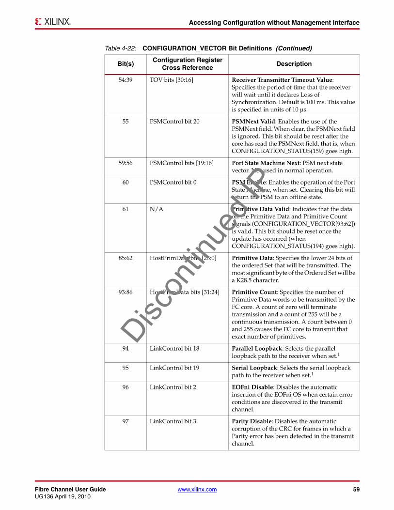
Fibre Channel User Guide www.xilinx.com 59UG136 April 19, 2010
Accessing Configuration without Management Interface
54:39 TOV bits [30:16] Receiver Transmitter Timeout Value: Specifies the period of time that the receiver will wait until it declares Loss of Synchronization. Default is 100 ms. This value is specified in units of 10 µs.
55 PSMControl bit 20 PSMNext Valid: Enables the use of the PSMNext field. When clear, the PSMNext field is ignored. This bit should be reset after the core has read the PSMNext field, that is, when CONFIGURATION_STATUS(159) goes high.
59:56 PSMControl bits [19:16] Port State Machine Next: PSM next state vector. Not used in normal operation.
60 PSMControl bit 0 PSM Enable: Enables the operation of the Port State Machine, when set. Clearing this bit will return the PSM to an offline state.
61 N/A Primitive Data Valid: Indicates that the data on the Primitive Data and Primitive Count signals (CONFIGURATION_VECTOR[93:62]) is valid. This bit should be reset once the update has occurred (when CONFIGURATION_STATUS(194) goes high).
85:62 HostPrimData bits [23:0] Primitive Data: Specifies the lower 24 bits of the ordered Set that will be transmitted. The most significant byte of the Ordered Set will be a K28.5 character.
93:86 HostPrimData bits [31:24] Primitive Count: Specifies the number of Primitive Data words to be transmitted by the FC core. A count of zero will terminate transmission and a count of 255 will be a continuous transmission. A count between 0 and 255 causes the FC core to transmit that exact number of primitives.
94 LinkControl bit 18 Parallel Loopback: Selects the parallel loopback path to the receiver when set.1
95 LinkControl bit 19 Serial Loopback: Selects the serial loopback path to the receiver when set.1
96 LinkControl bit 2 EOFni Disable: Disables the automatic insertion of the EOFni OS when certain error conditions are discovered in the transmit channel.
97 LinkControl bit 3 Parity Disable: Disables the automatic corruption of the CRC for frames in which a Parity error has been detected in the transmit channel.
Table 4-22: CONFIGURATION_VECTOR Bit Definitions (Continued)
Bit(s)Configuration Register
Cross ReferenceDescription
Discon
tinue
d IP

60 www.xilinx.com Fibre Channel User GuideUG136 April 19, 2010
Chapter 4: Designing with the Core
98 LinkControl bit 0 Transmit Speed (LSB): Selects the transmit serial data baud rate.
• 0x0 – Slower speed• 0x1 – Faster speed
This bit has no meaning when not in multi-rate configuration.
99 LinkControl bit 16 Receive Speed (LSB): Selects the receive serial data baud rate:
• 0x0 – Slower speed• 0x1 – Faster speed
This bit has no meaning when not in multi-rate configuration.
100 LinkControl bit 4 Transmit MGT Disable: Disables the operation of the transmit channel within the MGT.
101 LinkControl bit 20 Receive MGT Disable: Disables the operation of the receive channel within the MGT.
102 OpticsControl bit 0 Transmit Disable: Disables the transmit laser when active (high)
106-103 LinkControl bits [24-21] Frame2RRDY IFG: Specifies the minimum separation for an RRDY primitive. Actual value will be one more than set here. For example, a value of ‘1’ will set an RRDY to be bounded by two IDLEs, both before and after. Only valid if bit 111 is active (high).
Important: This results in the core functioning outside the FC-FS standard. Use with caution.
110-107 LinkControl bits [28-25] Frame2Frame IFG: Specifies the minimum separation between two frames. Actual value will be one more than set here. For example, a value of ‘1’ will set a minimum of two IDLE words between two contiguous frames. Only valid if bit 111 is active (high).
Important: This results in the core functioning outside the FC-FS standard. Use with caution.
111 LinkControl bit 29 IFG Adjust: Enables the use of custom IFG settings when active (high). When clear, the default settings are used.
Important: This results in the core functioning outside the FC-FS standard. Use with caution.
Table 4-22: CONFIGURATION_VECTOR Bit Definitions (Continued)
Bit(s)Configuration Register
Cross ReferenceDescription
Discon
tinue
d IP

Fibre Channel User Guide www.xilinx.com 61UG136 April 19, 2010
Accessing Configuration without Management Interface
Configuration Status Vector Description
112 SpeedNegControl bit 7 Speed Negotiation Start Request: Request for Speed Negotiation process to start when active (high)
113 LinkControl bit 1 Transmit Speed (MSB): Together with bit 98 (LSB), selects the transmit serial data baud rate. This should always be set to '0'.
This bit has no meaning when not in multi-rate configuration.
114 LinkControl bit 17 Receive Speed (MSB): Together with bit 99 (LSB), selects the receive serial data baud rate. This should always be set to '0'.
This bit has no meaning when not in multi-rate configuration.
1. Loopback inside the MGT(s).
Table 4-22: CONFIGURATION_VECTOR Bit Definitions (Continued)
Bit(s)Configuration Register
Cross ReferenceDescription
Table 4-23: CONFIGURATION_STATUS Bit Definitions
Bit(s)Configuration Register
Cross ReferenceDescription
15:0 BBSCNRDY bits [15:0] Transmitted R_RDY: Indicates the number of R_RDYs transmitted since the last BB_SCr was sent.
31:16 BBSCNFrame bits [15:0] Transmitted Frames: Indicates the number of frames transmitted since the last BB_SCs was sent.
47:32 OutStdRRDYCredit bits [15:0]
Outstanding R_RDYCredit: Indicates the amount of credit (R_RDYs) currently pending for return to the far end device. The R_RDY counter keeps track of how many R_RDY primitives need to be transmitted based on how many frames were received. Credit is returned for frames that have a valid SOF and have at least one word of valid data following the SOF, independent of the validity of the CRC.
63:48 OutStdB2BCredit bits [15:0] Outstanding B2BCredit: Indicates the amount of Buffer-to-Buffer credit that is currently available for sending frames to the far end device.
79:64 BBSCNRDY bits [31:16] Received R_RDY: Indicates the number of R_RDYs received since the last BB_SCr was received.
Discon
tinue
d IP

62 www.xilinx.com Fibre Channel User GuideUG136 April 19, 2010
Chapter 4: Designing with the Core
95:80 BBSCNFrame bits [31:16] Received Frames: Indicates the number of frames received since the last BB_SCs was received.
96 N/A Buffer-to-Buffer State Change Number Valid: Indicates to the FC core that it should update the BB_SC_N register with the value on the Buffer-to-Buffer State Change Number signal.
100:97 BB_SC_N bits [3:0] Buffer-to-Buffer State Change Number: Indicates the log2 of the B2B_Credit Recovery Modulus.
101 N/A Buffer-to-Buffer State Change Number Read: Indicates that the BB_SC_N register has been updated.
102 B2BCredit bit 16 Buffer-to-Buffer Immediate Update: Indicates to the FC core that it should immediately update its B2BCredit counter with the data on the Buffer-to-Buffer Credit signal.
103 N/A Buffer-to-Buffer Credit Valid: Indicates to the FC core that the data on Buffer-to-Buffer Credit signal is valid and to update the B2BCredit counter when the PSM transitions to the Active state.
119:104 B2BCredit bits [15:0] Buffer-to-Buffer Credit: Indicates the number of frames that can be sent on this link prior to receiving an R_RDY reply.
120 N/A Buffer-to-Buffer Immediate Update Read: Indicates that the B2BCredit counter has been immediately updated.
121 N/A Buffer-to-Buffer Credit Read: Indicates that the B2BCredit counter has been updated.
137:122 TOV bits [15:0] Offline State Timeout Value: Indicates the period of time that the transmitter will transmit OLS. Default is 5 ms. This value is specified in units of 10 µs.
153:138 TOV bits [31:16] Receiver Transmitter Timeout Value: Indicates the period of time that the receiver will wait until it declares Loss of Synchronization. Default is 100 ms. This value is specified in units of 10 µs.
Table 4-23: CONFIGURATION_STATUS Bit Definitions (Continued)
Bit(s)Configuration Register
Cross ReferenceDescription
Discon
tinue
d IP

Fibre Channel User Guide www.xilinx.com 63UG136 April 19, 2010
Accessing Configuration without Management Interface
154 PSMControl bit 20 PSMNext Valid: Indicates the use of the PSMNext field. When clear, the PSMNext field is ignored. This bit should be reset after the core has read the PSMNext field—the next clock pulse.
158:155 PSMControl bits [19:16] Port State Machine Next: Next State vector. Should be the code for a Major State - see Table 4-13.
159 N/A Port State Machine Next Read: Indicates that the PSMNext field has been updated.
160 PSMControl bit 0 PSM Enable: Indicates the operation of the Port State Machine when set. Clearing this bit will return the PSM to an offline state.
161 N/A Primitive Data Valid: Indicates that the data on the Primitive Data and Primitive Count signals is valid.
185:162 HostPrimData bits [23:0] Primitive Data: Indicates the lower 24 bits of the ordered Set that will be transmitted. The most significant byte of the Ordered Set will be a K28.5 character.
193:186 HostPrimData bits [31:24] Primitive Count: Indicates the number of Primitive Data words to be transmitted by the FC core. A count of zero will terminate transmission and a count of 255 will be a continuous transmission. A count between 0 and 255 will cause the FC core to transmit that exact number of primitives.
194 N/A Primitive Data Read: Indicates that the Primitive Data and Primitive Count registers have been updated.
198:195 PSMStatus bits [19:15] Port State Machine: Current state vector.
199 PSMControl bit 1 Statistics Enable: Indicates that the collection of FC statistics is enabled.
205:200 LinkStatus bits [21:16] Loss of Synchronization Finite State Machine: Loss of Synchronization FSM output vector. This vector indicates the current state of the receive channel synchronization process and is used to ensure that the received bit stream has been decoded correctly.
206 LinkControl bit 18 Parallel Loopback: Indicates the parallel loopback path to the receiver when set.
207 LinkControl bit 19 Serial Loopback: Indicates the serial loopback path to the receiver when set.
Table 4-23: CONFIGURATION_STATUS Bit Definitions (Continued)
Bit(s)Configuration Register
Cross ReferenceDescription
Discon
tinue
d IP

64 www.xilinx.com Fibre Channel User GuideUG136 April 19, 2010
Chapter 4: Designing with the Core
208 LinkControl bit 2 EOFni Disable: Indicates the automatic insertion of the EOFni OS when certain error conditions are discovered in the transmit channel.
209 LinkControl bit 3 Parity Disable: Indicates the automatic corruption of the CRC for frames in which a Parity error has been detected in the transmit channel.
210 LinkControl bit 0 Transmit Speed(LSB): Together with bit 236 (MSB), indicates the transmit serial data baud rate: 1
• 0x0 – Slower speed• 0x1 – Faster speed
211 LinkControl bit 16 Receive Speed (LSB): Together with bit 237 (MSB), indicates the receive serial data baud rate: 1
• 0x0 – Slower speed• 0x1 – Faster speed
212 LinkControl bit 4 Transmit MGT Disable: Indicates the operation of the transmit channel within the MGT. 1
213 LinkControl bit 20 Receive MGT Disable: Indicates the operation of the receive channel within the MGT.1
214 OpticsStatus bit 16 Loss of Signal: Indicates loss of signal at the optical receiver when active (high) as reported by the optics device. This signal will be active when the received optical power is below the worst-case receiver sensitivity.
215 OpticsStatus bit 1 Module Not Present: Indicates that an optical transceiver is not present when active (high). This signal is used for Small Form-factor Pluggable (SFP) applications so that the system can determine whether or not a transceiver is installed. For fixed optical applications, this signal should be tied low (inactive).
216 OpticsStatus bit 0 Transmit Fault: Indicates a transmit laser fault when active (high) as reported by the optics device.
217 OpticsControl bit 0 Transmit Disable: Indicates the transmit laser when active (high).
Table 4-23: CONFIGURATION_STATUS Bit Definitions (Continued)
Bit(s)Configuration Register
Cross ReferenceDescription
Discon
tinue
d IP

Fibre Channel User Guide www.xilinx.com 65UG136 April 19, 2010
Accessing Configuration without Management Interface
221-218 LinkControl bits [24:21] Frame2RRDY IFG: Custom Credit primitive protection. This value indicates the number of IDLEs which must appear before and after each Credit primitive. Valid values are 0-8 and represent one less than the actual value used in the core. In other words, a value of 2 will set the minimum Credit primitive protection to 3 in the core. Only valid if bit 226 is active (high). This will result in the core behaving outside the FC-FS standard - use with caution!
225-222 LinkControl bits [28:25] Frame2Frame IFG: Custom minimum IFG. This value indicates the user set programmable minimum separation between 2 frames. Valid values are 0-8 and represent one less than the actual value used in the core. In other words, a value of 2 will set the minimum IFG to 3 in the core. Only valid if bit 226 is active (high). This will result in the core behaving outside the FC-FS standard - use with caution!
226 LinkControl bit 29 IFG Adjust: Indicates that custom IFG settings are enabled when active (high).
227 SpeedNegStatus bits 0 Speed Negotiation Busy: Indicates that Speed Negotiation is running the negotiation algorithm when active (high)
229-228 SpeedNegStatus bit [2:1] Speed Negotiation Result: Indicates the result of Speed Negotiation. Only valid when bit 230 is active (high)
230 SpeedNegStatus bit 3 Speed Negotiation Result Valid: Indicates that the Result of Speed Negotiation (bits 228-229) is valid when active (high)
231 SpeedNegControl bit 7 Speed Negotiation Start Requested: Indicates that Speed Negotiation Start has been requested when active (high)
235-232 N/A Capabilities Vector: Indicates that the core is capable of 2n-232 Gbps speed, where n = 232..235 that is, which of these bits are set.
236 LinkControl bit 1 Transmit Speed (MSB): Together with bit 210 (LSB), indicates the receive serial data baud rate: 1
• 0x0 – Slower speed• 0x1 – Faster speed
Table 4-23: CONFIGURATION_STATUS Bit Definitions (Continued)
Bit(s)Configuration Register
Cross ReferenceDescription
Discon
tinue
d IP
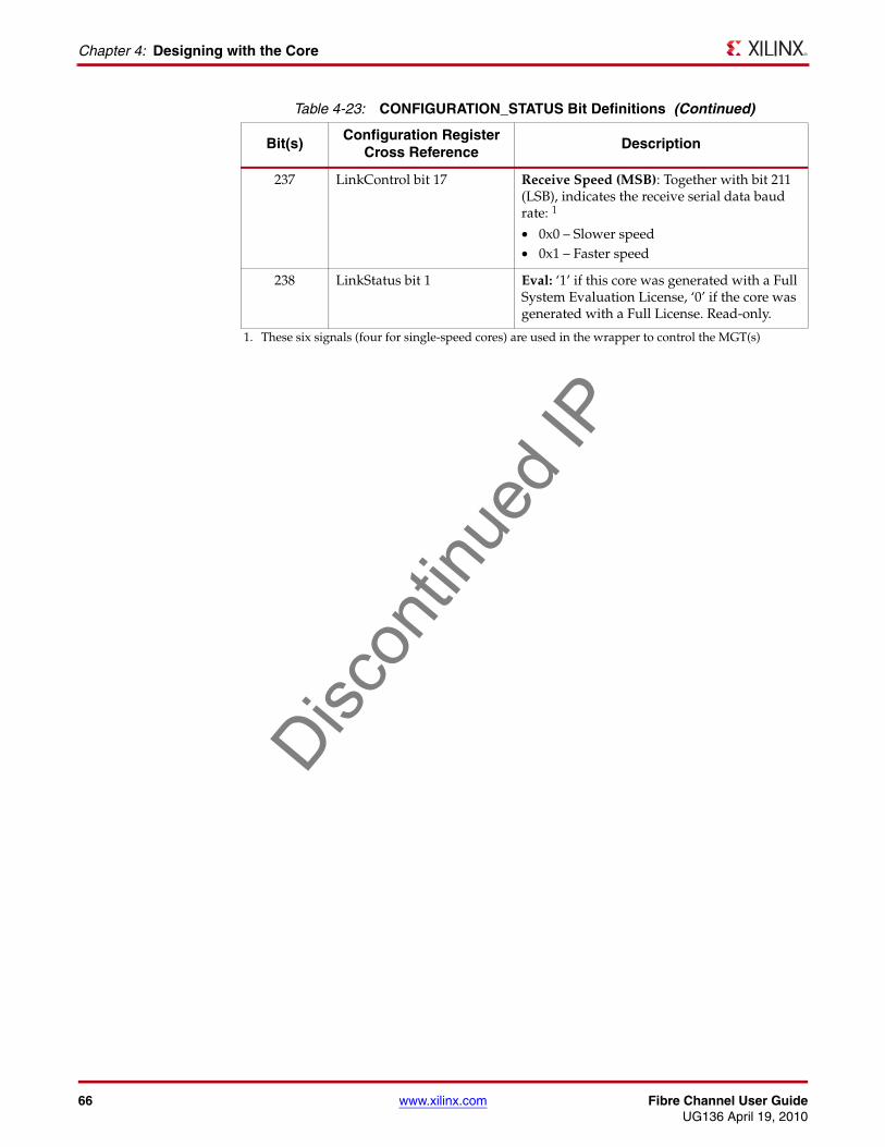
66 www.xilinx.com Fibre Channel User GuideUG136 April 19, 2010
Chapter 4: Designing with the Core
237 LinkControl bit 17 Receive Speed (MSB): Together with bit 211 (LSB), indicates the receive serial data baud rate: 1
• 0x0 – Slower speed• 0x1 – Faster speed
238 LinkStatus bit 1 Eval: ‘1’ if this core was generated with a Full System Evaluation License, ‘0’ if the core was generated with a Full License. Read-only.
1. These six signals (four for single-speed cores) are used in the wrapper to control the MGT(s)
Table 4-23: CONFIGURATION_STATUS Bit Definitions (Continued)
Bit(s)Configuration Register
Cross ReferenceDescription
Discon
tinue
d IP

Fibre Channel User Guide www.xilinx.com 67UG136 April 19, 2010
Statistics Gathering
Statistics Gathering
Automatic Statistics GatheringIf the Statistics Gathering block was selected during core generation, during operation the core may collect statistical information on the success and failure of various operations. These statistics are accessed by the client through the Management Interface. All statistics are 32 bits wide and are read-writable; although, the write operation is only included for testing purposes and should not be used in normal circumstances. As these registers are reset when read, the output data is only valid for a single clock cycle.
The statistics counters increment when a given event occurs within the FC core that has an associated counter. The FC core outputs a single clock cycle pulse for each event occurrence. If the FC core statistics output is active for more than one clock cycle, the given statistics counter will increment once for each clock cycle that the signal is active.
Upon a read transaction, the specific statistics counter is reset so the value read represents the number of events since the last read. It is therefore up to your application to keep the cumulative value of the statistics to track the statistics on a continuous basis.
The statistics are updated and stored in distributed RAM in the FPGA. To provide a fast access time to the statistics, no updates can occur to the statistics while they are being read by the host. To allow for this, the statistics block contains some additional register-based storage. However, due to the finite amount of this register based storage, there is the potential for statistics updates to be missed if the statistics are read continuously. It is advised that the client not poll all the statistics more frequently than once every 10 microseconds. As the statistics are 32-bits wide the statistics can be polled much less frequently than this. If any of the statistics do reach their maximum count, they will maintain this value until read.
As the Statistics are stored in RAM they cannot be explicitly reset except by reconfiguration of the chip. The recommended method to reset the statistics is to read from each address in turn. This process should also be followed after every core reset.
The Receive Link Error Statistics are described in Table 4-24. For further information on Link Errors, see Table E.1, FC FS v1.9 draft standard document.
Table 4-24: Receive Link Error Statistics Registers
Address Name Description
0x080 RxLinkFailureCnt Receive Link Failure Count: Indicates the number of Link Failure (LF1 only) events since this register was last read.1
0x084 RxLossSyncCnt Receive Loss of Synchronization Count: Indicates the number of Loss of Synchronization events since this register was last read.
0x088 RxLossSigCnt Receive Loss of Signal Count: Indicates the number of Loss of Signal events since this register was last read.
0x08C Rx10bErrCnt Receive Decoder Error Count: Indicates the number of 10-bit decoder errors since this register was last read.
Discon
tinue
d IP

68 www.xilinx.com Fibre Channel User GuideUG136 April 19, 2010
Chapter 4: Designing with the Core
The Transmit Link Error Statistics are described in Table 4-25.
0x090 RxAlignErrCnt Receive Alignment Error Count: Indicates the number of word Alignment Errors since this register was last read.
0x094 RxOsdErrCnt Receive Ordered Set Disparity Error Count: Indicates the number of Ordered Set Disparity errors since this register was last read.
0x098 RxEOFaCnt Receive EOF Abort Count: Indicates the number of EOFa primitives received since this register was last read.
0x09C RxEOFErrorCnt Receive EOF Error Count: Indicates the number of frames received that were missing an EOF since this register was last read.
0x0A0 RxCRCErrorCnt Receive CRC Error Count: Indicates the number of frames received that had an invalid CRC since this register was last read.
1. All statistics counter registers are reset after each read.
Table 4-25: Transmit Link Error Statistics Registers
Address Name Description
0x0A4 TxEOFaCnt Transmit EOF Abort Count: Indicates the number of frames transmitted with an EOFa since this register was last read.
0x0A8 TxCRCErrorCnt Transmit CRC Error Count: Indicates the number of frames transmitted that had an invalid CRC since this register was last read.
0x0AC TxParityErrorCnt Transmit Parity Error Count: Indicates the number of frames transmitted with a parity error since this register was last read.
0x0B0 TxEOFniCnt Transmit EOFni Count: Indicates the number of frames transmitted with an EOFni since this register was last read.
Table 4-24: Receive Link Error Statistics Registers (Continued)
Address Name Description
Discon
tinue
d IP
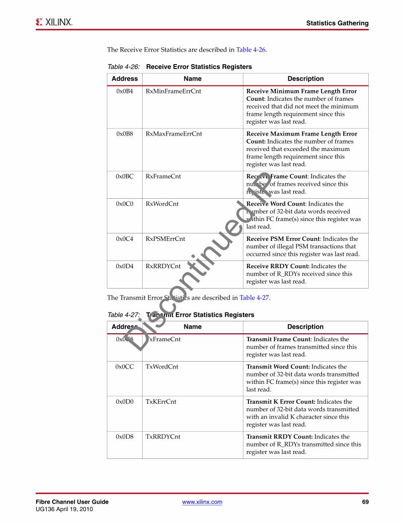
Fibre Channel User Guide www.xilinx.com 69UG136 April 19, 2010
Statistics Gathering
The Receive Error Statistics are described in Table 4-26.
The Transmit Error Statistics are described in Table 4-27.
Table 4-26: Receive Error Statistics Registers
Address Name Description
0x0B4 RxMinFrameErrCnt Receive Minimum Frame Length Error Count: Indicates the number of frames received that did not meet the minimum frame length requirement since this register was last read.
0x0B8 RxMaxFrameErrCnt Receive Maximum Frame Length Error Count: Indicates the number of frames received that exceeded the maximum frame length requirement since this register was last read.
0x0BC RxFrameCnt Receive Frame Count: Indicates the number of frames received since this register was last read.
0x0C0 RxWordCnt Receive Word Count: Indicates the number of 32-bit data words received within FC frame(s) since this register was last read.
0x0C4 RxPSMErrCnt Receive PSM Error Count: Indicates the number of illegal PSM transactions that occurred since this register was last read.
0x0D4 RxRRDYCnt Receive RRDY Count: Indicates the number of R_RDYs received since this register was last read.
Table 4-27: Transmit Error Statistics Registers
Address Name Description
0x0C8 TxFrameCnt Transmit Frame Count: Indicates the number of frames transmitted since this register was last read.
0x0CC TxWordCnt Transmit Word Count: Indicates the number of 32-bit data words transmitted within FC frame(s) since this register was last read.
0x0D0 TxKErrCnt Transmit K Error Count: Indicates the number of 32-bit data words transmitted with an invalid K character since this register was last read.
0x0D8 TxRRDYCnt Transmit RRDY Count: Indicates the number of R_RDYs transmitted since this register was last read.
Discon
tinue
d IP

70 www.xilinx.com Fibre Channel User GuideUG136 April 19, 2010
Chapter 4: Designing with the Core
Using the Statistics VectorThe core pinout includes a Statistics Vector which provides the real-time statistics increments for each statistic. This vector is the input to the statistics block when included in the core and provides an increment to the corresponding statistic counter on each clock cycle whenever that particular bit in the vector is high. This vector is available whether the core contains the optional statistics block or not, and allows for the creation of external statistic registers. The Statistics Vector is described in the following table.
Table 4-28: STATISTICS_VECTOR Bit Description
STATISTICS_VECTOR Bit Name Statistic Increment
22 txrrdy txrrdycnt(0x0d8)
21 rxrrdy rxrrdycnt(0x0d4)
20 txkerror txkerrcnt (0x0d0)
19 txword txwordcnt (0x0cc)
18 txframe txframecnt (0x0c8)
17 rxpsmerror rxpsmerrcnt (0x0c4)
16 rxword rxwordcnt (0x0c0)
15 rxframe rxframecnt (0x0bc)
14 rxmaxframeerr rxmaxframeerrcnt (0x0b8)
13 rxminframeerr rxminframeerrcnt (0x0b4)
12 txeofni txeofnicnt (0x0b0)
11 txparityerror txparityerrorcnt (0x0ac)
10 txcrcerror txcrcerrorcnt (0x0a8)
9 txeofa txeofacnt (0x0a4)
8 rxcrcerror rxcrcerrorcnt (0x0a0)
7 rxeoferror rxeoferrorcnt (0x09c)
6 rxeofa rxeofacnt (0x098)
5 rxosderror rxosderrcnt (0x094)
4 rxalignerror rxalignerrcnt (0x090)
3 rx10berror rx10berrcnt (0x08c)
2 rxlosssignal rxlosssigcnt (0x088)
1 rxlosssync rxlosssynccnt (0x084)
0 rxlinkfailure rxlinkfailurecnt (0x080)
Discon
tinue
d IP

Fibre Channel User Guide www.xilinx.com 71UG136 April 19, 2010
Credit Management
Credit ManagementCredit Management manages the amount of data that can be transmitted. It also controls the amount of credit that can be returned based on the received frames and status of the Client Interface. This section is only applicable when the optional Credit Management block has been included in the core.
Understanding CreditCredit management is integral to the Fibre Channel speed and data integrity, and so it is important that the concept is understood.
An example of a credit management problem is described here to aid this understanding:
• Port A and Port B are connected by a length of fibre.
• Using the speed of light in the fibre, we can calculate how long a stretch of fibre will contain a maximum-sized FC frame.
• We can then calculate how many maximum-sized FC Frames will fit, end-to-end in the fibre. For this example, assume that the number is 5. Remember that this fibre is bidirectional (that is, two fibres).
• We can say that if Port A transmitted a frame and then had to wait for an acknowledgement (r_rdy) before transmitting another frame, the delay between frames would be equivalent to ten frames (5 in either direction) delay. (10 frames x 2148 bytes x 10 bits per byte = 214,800 bits)
• At 1 Gbps, each frame would last 1/5000th of a second.
• If Port A did not wait for the r_rdy, it would be possible to transmit frames continuously but not guarantee their reception, which is not allowed for Class 1 (connect), Class 2, or Class F frames.
• If instead Port A had empirical evidence that Port B had at least 10 buffers free, Port A could send frames continuously with the r_rdy for the first frame arriving just after the tenth frame was sent, in time to allow the eleventh frame to be transmitted and so forth.
• This assumes that Port B can clear its receive buffers as fast as the frames arrive in those buffers, with some (5 frames worth) delay. An r_rdy should be transmitted from Port B only when it clears a buffer.
X-Ref Target - Figure 4-14
Figure 4-14: Buffer-to-Buffer Credit
214800 bits 15000------------ Gigabits≈ 1
5000------------ ondssec≈
Port A
TX
RX
Port B
TX
RXRX buffers
R_RDY R_RDY2 R_RDY3 R_RDY4
Frames1.5
Frame 10 Frame 9 Frame 8 Frame 7 Frame 6
for Frame 1
Discon
tinue
d IP
72 www.xilinx.com Fibre Channel User GuideUG136 April 19, 2010
Chapter 4: Designing with the Core
Buffer-to-Buffer Credit CounterThe Buffer-to-Buffer Credit counter keeps track of how many frames can be transmitted to the attached device. This counter is loaded with its initial value when the PSM enters the Active state or when it is forced through the use of the Immediate Update bit in the B2BCredit configuration register. The initial value loaded on transition to Active state is the Buffer-to-Buffer Credit field in the B2BCredit configuration register; see Table 4-16. The value is reset back to the default value of one on a linkinitorfailure condition.
The Buffer-to-Buffer Credit counter is incremented for each r_rdy that is received and decremented for each SOF that is transmitted. New frames will only be transmitted if this counter has a value greater than zero.
R_RDY Transmit CounterCredit is returned for frames that have a valid SOF and have at least one word of valid data following the SOF, independent to the validity of the CRC.
The r_rdy counter keeps track of how many r_rdy primitives need to be transmitted based on how many frames were received. This counter is reset to a value of zero when the PSM enters the Active state. For each frame received that has a valid SOF for buffer-level credit management purposes, the r_rdy counter is incremented. In addition, the R_RDY counter is decremented each time an r_rdy primitive is transmitted.
The Client Interface can assert the applybackpressure signal to prevent the return of R_RDYs. On releasing applybackpressure, any pending r_rdy primitives are transmitted within the next interframe gap. The use of this signal is not required under normal conditions. See “Throttling Credit Primitives,” page 45 for more information.
Credit RecoveryAs described in FC-FS v1.9 Section 18.5.11, there exists a method to detect both missing frames and missing r_rdy primitives and adjust the credit counter(s) accordingly. In the event of missing r_rdy primitives, the OutstandingB2BCredit will be incremented by the missing amount. Similarly, the amount of missing frames will increment the outstandingrrdycredit counter and return the missing credit.
Using BBCreditAs mentioned previously, the default value of one is used for BBCredit unless or until a new value is written to the B2BCredit register, and its use is either forced (see next subsection) or automatically picked up on a transition to Active state.
Immediate Update
It is possible to use bit 16 in the B2BCredit register to cause an immediate update to the BBCredit value. This function would not normally be used.
Update on Link Reset
According to the Fibre Channel standards, BBCredit values should be exchanged during Port Initialization but not used until after a Link Reset command. The Fibre Channel core does this automatically, in that once the BBCredit value has been programmed into the B2BCredit register (without Immediate Update), the next time the Port State Machine enters the Active state that BBCredit value will be used by the core.
Discon
tinue
d IP

Fibre Channel User Guide www.xilinx.com 73UG136 April 19, 2010
Speed Negotiation
Port Login and BBCredit
The sequence of events for setting and using BBCredit correctly are:
• Initialize Link
• Begin Port Initialization (send and receive PLOGI, FLOGI or ELP)
• Parse the far-end port BBCredit value and bb_sc_n value from the Login frame
• Write that BBCredit value into B2BCredit register
• Write the bb_sc_n value into the bb_sc_n register
• One of the following:
♦ Wait for LR primitive sequence to trigger Link Reset protocol or
♦ Force Link Reset by writing ‘10100’ to PSMControl Register, bits 20..16.
After Link Reset is complete, the new BBCredit value is used by the core.
BBCredit and Frame Buffers
While a BBCredit value of up to 65535 may be used for the core (advertised during Login), it is up to you to provide enough frame buffers to support their specific application. A typical BBCredit value of 16 requires 16*2148 = 34368 bytes of memory.
Default BBCredit and Frame Buffers
Despite the default value of one for BBCredit, the core itself does not buffer any received frames, and you must provide a mechanism (for example, a FIFO) to receive at least a single frame of data.
Speed NegotiationIf the optional Speed Negotiation was selected during generation of a multi-speed core, the core is capable of performing speed negotiation. The interface for the Speed Negotiation block is shown in Figure 4-15. The additional logic will implement the FC FS Section 28 Link Speed Negotiation algorithm. This enables a core which is capable of multiple data transfer rates to determine the highest speed common to the communicating devices. There are two registers that are associated with Speed Negotiation, and these are detailed in Table 4-29 and Table 4-30.X-Ref Target - Figure 4-15
Figure 4-15: Speed Negotiation Interface
Core2SpeedNegCtl[78:0]
To/From FC Core
SpeedNegCtl2Core [13:0]
Speed NegotiationController
Discon
tinue
d IP

74 www.xilinx.com Fibre Channel User GuideUG136 April 19, 2010
Chapter 4: Designing with the Core
Table 4-29 shows the Speed Negotiation Control register.
Table 4-30 shows the Speed Negotiation Status register.
Table 4-29: SpeedNegControl Register (0x070)
BitsConfiguration
Vector bitsConfiguration
Status bitsR/W Description
31:8 N/A N/A N/A Reserved
7 112 231 R/W Speed Negotiation Start Request: Indicates that the Speed Negotiation has been requested to start when active (high).
6:0 N/A N/A N/A Reserved
Table 4-30: SpeedNegStatus Register (0x074)
BitsConfiguration
Status bitsR/W Description
31:20 N/A N/A Reserved
19:16 235-232 R Capabilities: Bit n indicates that the core is capable of 2n-16 Gbps speed. For example, if bits 16 and 17 are set (high) the core is capable of both 1 and 2 Gbps speeds.
15:4 N/A N/A Reserved
3 230 R Speed Negotiation Result Valid: Indicates the result of speed negotiation is valid when active (high).
2:1 229-228 R Speed Negotiation Result: Indicates the result of Speed Negotiation. Only valid when bit 3 is active (high).
0 227 R Speed Negotiation Busy: Indicates that the speed negotiation process is currently running when active (high).Disc
ontin
ued I
P

Fibre Channel User Guide www.xilinx.com 75UG136 April 19, 2010
Speed Negotiation
Performing Speed NegotiationPerforming speed negotiation requires the following steps:
Without Management Interface
When the core is generated without Management Interface, do the following:
• Ensure core PSM is in the Offline state by setting Configuration Vector bit 60, PSM Enable, inactive (low).
• Set Configuration Vector bit 112 to ‘1.’
• Wait until Configuration Status bit 227 is active (high) which indicates that speed negotiation is being performed.
• Wait until Configuration Status bit 227 is inactive (low) and bit 230 is active (high) which indicates that the process has completed successfully. If bit 230 is inactive (low), the speed negotiation process has failed and must be restarted.
• At this point speed negotiation is complete and the result can be seen on Configuration Status bits 229-228.
• Assign the results of speed negotiation to core Rx speed (configuration_vector bits 113 and 98) and Tx speed (configuration_vector bits 114 and 99).
• Set Configuration Vector bit 112 to ‘0.’
• Core operation may begin as normal by enabling the PSM.
• To cancel Speed negotiation, set Configuration Vector bit 112 to ‘0.’
With Management Interface
When the core is generated with the Management Interface, do the following:
• Ensure core PSM is in the Offline state by clearing bit 0 in register 0x020,PSMControl.
• Write a ‘1’ to register 0x70 bit 7, which is the Speed Negotiation Start Request bit.
• Read register 0x74 to ensure bit 0 is active (high) which indicates that speed negotiation is being performed.
• Read register 0x74 until bit 0 is inactive (low). Bit 3indicates that the process has completed, and the result is valid when active (high). If bit 3 is inactive (low), the speed negotiation process has failed and must be restarted.
• At this point speed negotiation is complete and the result can be obtained by reading register 0x74 bits 2 (msb) and 1 (lsb).
• Write this result to linkcontrol register (0x010) bits 17:16 (Rx Speed) and 1:0 (TxSpeed).
• Write a ‘0’ to bit 7 of register 0x70, which clears the Speed Negotiation Start Request bit.
• Core operation may begin as normal by enabling the PSM.
• To cancel Speed negotiation, write ‘0’ to bit 7 of register 0x70.
Note: The Speed Negotiation block is optional.
It is perfectly reasonable to perform speed negotiation in software without reference to this speed negotiation block. Simply generate the core without the speed negotiation option and use the configuration and status interfaces (with or without the host interface) to implement the speed negotiation algorithm as described in the FC-FS standard document.
Discon
tinue
d IP

76 www.xilinx.com Fibre Channel User GuideUG136 April 19, 2010
Chapter 4: Designing with the Core
Turning on the speed negotiation option in the CORE Generator software will include a small amount of extra logic in the core, and generate a separate speed negotiation netlist that you must instantiate at the wrapper level (the same level as the MGT and DCM instantiation). The simple interface between the core and the speed negotiation block has been designed to make it simple for your own speed negotiation block to be substituted for the Xilinx supplied netlist.
Table 4-31 and Table 4-32 detail the speed negotiation control vectors to enable users to create their own speed negotiation blocks. All bits of speednegctl2core must be connected. Unused bits of core2speednegctl should be left open to allow the synthesis tools to remove the unused logic from the core.
Table 4-31: SpeedNegCtl2Core
Bit(s)Configuration Register
Cross ReferenceDescription
13 N/A Rx Error Select: Selects either LOSync (when low) or 10bit and Alignment Errors (when high).
12 opticscontrol bit 0 Transmit Disable: Disables the Transmit laser when active (high).
11 linkcontrol bit 20 Receive MGT Disable: Disables the operation of the receiver channel with the MGT when active (high).
10:9 linkcontrol bits [17:16] Receive Speed: Selects the receive serial data baud:
• 0x0 = Slower speed or 1 Gbps• 0x1 = Faster speed or 2 Gbps or 4 Gbps
8 linkcontrol bit 4 Transmit MGT Disable: Disables the operation of the transmit channel with the MGT when active (high).
7:6 linkcontrol bits [1:0] Transmit Speed: Selects the transmit serial data baud:
• 0x0 = Slower speed or 1 Gbps• 0x1 = Faster speed or 2 Gbps or 4 Gbps
5 N/A Reset Speed Neg Stat counter: Resets the Speed Negotiation stats counter.
4 speednegstatus bit 0 Speed Negotiation Busy: Indicates that the speed negotiation process is currently running when active (high).
Discon
tinue
d IP

Fibre Channel User Guide www.xilinx.com 77UG136 April 19, 2010
Speed Negotiation
3 speednegstatus bit 3 Speed Negotiation Result Valid: Indicates the result of speed negotiation is valid when active (high).
2:1 speednegstatus bits [2:1] Speed Negotiation Result: Indicates the result of Speed Negotiation. Only valid when bit 3 is active (high).
0 N/A Speed Negotiation Mode: When active (high), the speed negotiation block is in control of the core speed setting. This bit should be set at the start of the speed negotiation process and cleared on completion.
Table 4-32: Core2SpeedNegCtl
Bit(s)Configuration Register
Cross ReferenceDescription
78:75 speednegstatus bits [19:16] Capabilities: Bit n indicates that the core is capable of 2n-75 Gbps speed. For example, if bits 75 and 76 are set (high) the core is capable of both 1 and 2 Gbps speeds.
74 N/A Rx Error Detected: Indicates that the error type selected by SpeedNegCtl2Core bit 13 has been detected.
73:42 N/A Optional Timer Counter: Indicates the state of the optional timer. Free-running 32-bit counter running off the main system clock (53.125 MHz for the 1 and 2 Gbps core)
41:10 rxlosssynccnt Receive Error Count: Indicates the number of receive errors (events indicated by bit 74). Reset by bit 5 of SpeedNegCtl2Core
9:8 psmstatus bits [19:18] Port State Machine: Current Major PSM state
7 linkstatus bit 0 Transmit Buffer Error: Indicates Transmit MGT buffer error.
6:1 linkstatus bits [21:16] Loss of Synchronization Finite State Machine: Loss of Synchronization FSM output vector. This vector indicates the current state of the receive channel synchronization process.
0 speednegcontrol bit 7 Speed Negotiation Start Request: Indicates that the Speed Negotiation has been requested to start when active (high).
Table 4-31: SpeedNegCtl2Core
Bit(s)Configuration Register
Cross ReferenceDescription
Discon
tinue
d IP

78 www.xilinx.com Fibre Channel User GuideUG136 April 19, 2010
Chapter 4: Designing with the Core
Loopback ModeWhen one of the internal MGT loopback modes is selected on the mgt_loopback[1:0] pins, your application must drive the following input signals at the correct levels. These would normally be driven by the PHY Optics module. In serial loopback mode, the transmit serial pins on the MGT must be terminated as if they were driving a PHY.
• mod_def_0_p - drive high
• tx_fault_p - drive low
• rx_los_p - drive low
Discon
tinue
d IP

Fibre Channel User Guide www.xilinx.com 79UG136 April 19, 2010
Chapter 5
Constraining the Core
This chapter defines the constraint requirements of the Fibre Channel core. An example user constraints file (UCF) is provided with the HDL wrapper file, which provides examples of constraint requirements for the design.
Detailed information about using the wrapper file and the example design can be found in the Fibre Channel Getting Started Guide.
Optional User ConstraintsThere are no optional user constraints for the core.
Required Constraints for Virtex-4 Devices
Device, Package, and Speedgrade SelectionThe part and package should be a Virtex®-4 device with the following attributes:
• Large enough to accommodate the core
• Contains a sufficient number of IOBs
• -10 speed grade for cores without Statistics Gathering, -11 with Statistics Gathering
Many more IOBs are required for the stand-alone HDL wrapper design than would normally be expected in the encapsulation of the Fibre Channel core by you.
I/O Location Constraints
MGT Location(s)
There are no restrictions on the placement of MGTs in Virtex-4 devices.
Clock Location(s)
There are no restrictions on the placement of Clock components in Virtex-4 devices.
Placement ConstraintsOther than the MGTs and Clock buffers, placement constraints may be required for the bufgmux(s) in the design. Examples are in the UCF delivered with the HDL wrapper for the core.
Discon
tinue
d IP

80 www.xilinx.com Fibre Channel User GuideUG136 April 19, 2010
Chapter 5: Constraining the Core
Timing ConstraintsExamples are provided in the UCF delivered with the HDL wrapper for the core.
Period(s) for Clock Net(s)
There is a single Period constraint of 4680 ps for the input clock for all configurations. From this, most other required constraints are derived by the tools. The system clock for multi-speed cores is specified with Period 9360 ps or 18720 ps, depending on the core.
Timespecs for Critical Logic
There will be single Timespecs in the UCF for cores generated with the Statistics Gathering block. This controls the timing of an address bus in the design and should not be removed.
Required Constraints for Virtex-5 Devices
Device, Package, and Speedgrade SelectionThe part and package should be a Virtex-5 device with the following attributes:
• Large enough to accommodate the core
• Contains a sufficient number of IOBs
• -2 speed grade
Many more IOBs are required for the stand-alone HDL wrapper design than would normally be expected in the encapsulation of the Fibre Channel core by you.
I/O Location Constraints
GTP Location(s)
There are no restrictions on the placement of GTP transceivers in Virtex-5 devices.
Clock Location(s)
There are no restrictions on the placement of Clock components in Virtex-5 devices.
Placement ConstraintsOther than the GTP transceivers and Clock buffers, placement constraints may be required for the bufgmux(s) in the design. Example(s) are in the UCF delivered with the HDL wrapper for the core.
Discon
tinue
d IP
Fibre Channel User Guide www.xilinx.com 81UG136 April 19, 2010
Required Constraints for Virtex-5 Devices
Timing ConstraintsExample(s) are in the UCF delivered with the HDL wrapper for the core.
Period(s) for Clock Net(s)
There is a single Period constraint of 4680 ps for the input clock for all configurations. From this, most other required constraints are derived by the tools. The system clock for multi-speed cores is specified with Period 9360 ps or 18720 ps, depending on the core.
Timespecs for Critical Logic
There are single Timespecs in the UCF for cores generated with the Statistics Gathering block. This controls the timing of an address bus in the design and should not be removed.
Discon
tinue
d IP

82 www.xilinx.com Fibre Channel User GuideUG136 April 19, 2010
Chapter 5: Constraining the Core
Discon
tinue
d IP

Fibre Channel User Guide www.xilinx.com 83UG136 April 19, 2010
Chapter 6
Design Considerations
This chapter provides information about design considerations associated with implementing the Fibre Channel core.
General Recommendations for RocketIO Transceiver Clock SpeedTo determine the RocketIO™ transceiver reference clock speed for the specific target device, see the respective RocketIO Transceiver User Guide and the information in this chapter.
• Virtex®-4 Device. Virtex-4 FPGA RocketIO Multi-Gigabit Transceiver User Guide (UG076)
• Virtex-5 Device. Virtex-5 FPGA RocketIO GTP Transceiver User Guide (UG196)
Clocking for Virtex-4 DevicesThe recommended clocking scheme varies for each speed configuration of the core. Most importantly, the clocking scheme is closely bound with the MGTs clocking requirements as defined in the following sections.
Discon
tinue
d IP
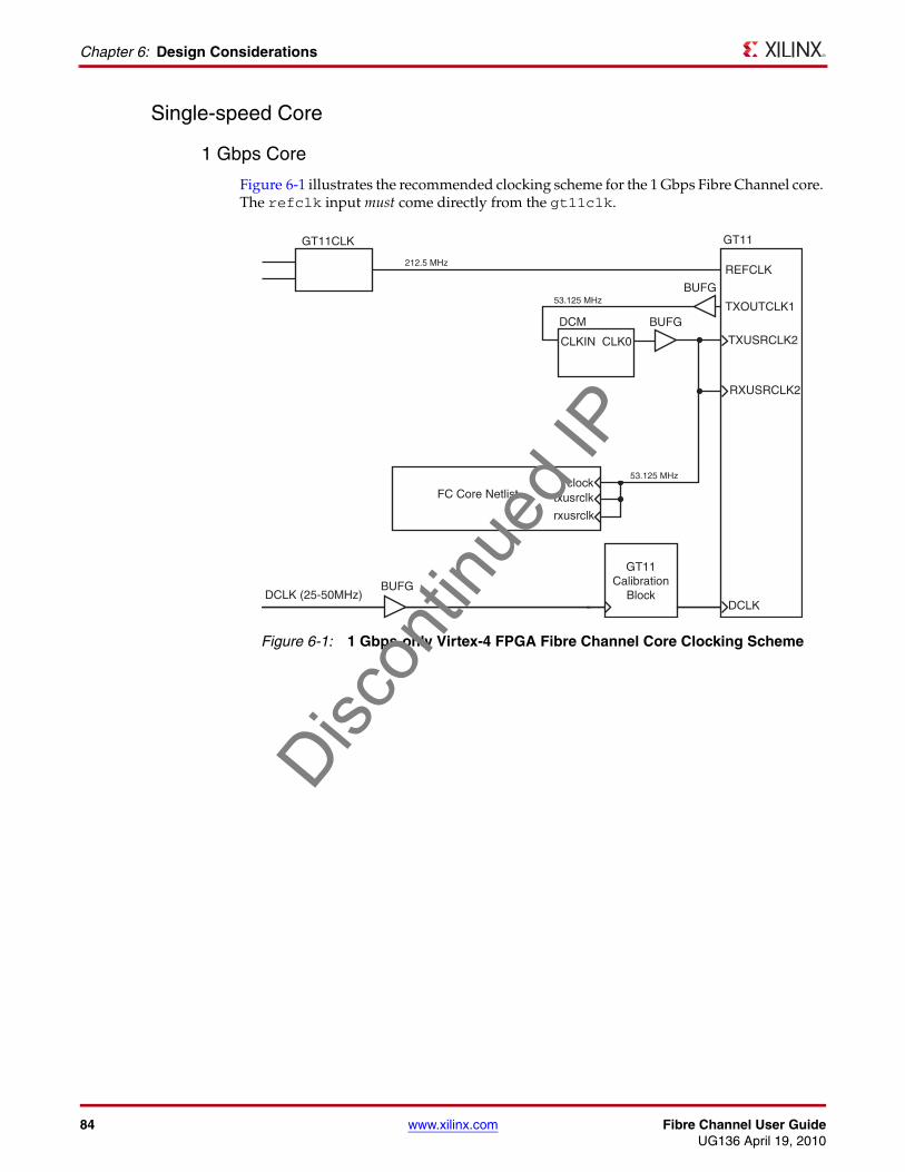
84 www.xilinx.com Fibre Channel User GuideUG136 April 19, 2010
Chapter 6: Design Considerations
Single-speed Core
1 Gbps Core
Figure 6-1 illustrates the recommended clocking scheme for the 1 Gbps Fibre Channel core. The refclk input must come directly from the gt11clk.X-Ref Target - Figure 6-1
Figure 6-1: 1 Gbps-only Virtex-4 FPGA Fibre Channel Core Clocking Scheme
GT11CLK GT11
REFCLK
TXUSRCLK2
TXOUTCLK1
RXUSRCLK2
DCLK
BUFG
BUFG
BUFG
DCM
CLKIN CLK0
FC Core Netlistclock
txusrclk
rxusrclk
212.5 MHz
53.125 MHz
53.125 MHz
GT11Calibration
BlockDCLK (25-50MHz)
Discon
tinue
d IP

Fibre Channel User Guide www.xilinx.com 85UG136 April 19, 2010
Clocking for Virtex-4 Devices
2 Gbps Core
Figure 6-2 illustrates the recommended clocking scheme for the 2 Gbps Fibre Channel core. X-Ref Target - Figure 6-2
Figure 6-2: 2 Gbps-only Virtex-4 FPGA Fibre Channel Core Clocking Scheme
GT11CLK GT11
REFCLK
TXUSRCLK2
TXOUTCLK1
RXUSRCLK2
DCLK
BUFG
BUFG
BUFG
BUFG
DCM
CLKIN CLK0
CLKDV
FC Core Netlistclock
txusrclk
rxusrclk
212.5 MHz
106.25 MHz
106.25 MHz
53.125 MHz
GT11Calibration
BlockDCLK (25-50MHz)
Discon
tinue
d IP

86 www.xilinx.com Fibre Channel User GuideUG136 April 19, 2010
Chapter 6: Design Considerations
4 Gbps Core
Figure 6-3 illustrates the recommended clocking scheme for the 4 Gbps Fibre Channel core.
Multi-speed Core
Primary Clocking Scheme
Dual-speed operation is more complicated. As the TX and RX paths can be run at different rates, the clocks are selected depending on the settings of tx_speed and rx_speed. The transmit clock is generated from within the GT11 as txoutclk1 and the receive clock is derived from the refclk signal through a DCM with the clkin_divide_by_2 attribute set. See Figure 6-4.
X-Ref Target - Figure 6-3
Figure 6-3: 4 Gbps-only Virtex-4 FPGA Fibre Channel Core Clocking Scheme
GT11CLK GT11
REFCLK
TXUSRCLK2
TXOUTCLK1
RXUSRCLK2
DCLK
BUFG
BUFG
BUFG
BUFG
BUFGMUX
DCM
CLKIN CLK0
CLKDV
FC Core Netlistclock
txusrclk
rxusrclk
212.5 MHz
212.5 MHz
212.5 MHz
106.25 MHz
GT11Calibration
BlockDCLK (25-50MHz)
Discon
tinue
d IP

Fibre Channel User Guide www.xilinx.com 87UG136 April 19, 2010
Clocking for Virtex-4 Devices
X-Ref Target - Figure 6-4
Figure 6-5 shows the clocking scheme for multi-speed 2/4 Gbps configuration. The core clock frequency is 106.25 MHz. The DCM does not have the clkin_divide_by_2 attribute set in this case. This is the only difference between the 2/4 and the 1/2 Gbps Virtex-4 device clocking scheme.
Figure 6-4: Multi-speed 1/2 Gbps Virtex-4 FPGA Fibre Channel Core Clocking Scheme
GT11CLK GT11
REFCLK
TXUSRCLK2
TXOUTCLK1
RXUSRCLK2
DCLK
BUFG
BUFG
BUFG
BUFG
BUFGMUXDCM
CLKIN_DIVIDE_BY_2=TRUE
CLKIN
CLKDV
CLK0
FC Core Netlistclock
txusrclk
rxusrclk
212.5 MHz
53.125/106.25 MHz
53.125/106.25 MHz
53.125MHz
GT11Calibration
Block
SpeedControl
DCLK (25-50MHz)
1
0Disc
ontin
ued I
P

88 www.xilinx.com Fibre Channel User GuideUG136 April 19, 2010
Chapter 6: Design Considerations
X-Ref Target - Figure 6-5
Fixed Multi-speed Clocking Scheme
If you want to implement a simplified multi-speed design where the RX and TX paths run at the same rate, ensure that tx_speed and rx_speed are the same. However, this configuration will not be capable of fully implementing the FC FS Section 28 Speed Negotiation Algorithm.
Clocking the User DesignUse the Clock output from the Fibre Channel core to drive logic and registers in your own design. If this is not possible, special care must be taken when crossing between clock domains, using whatever buffering techniques are applicable.
Figure 6-5: Multi-speed 2/4 Gbps Virtex-4 FPGA Fibre Channel Core Clocking Scheme
GT11CLK GT11
REFCLK
TXUSRCLK2
TXOUTCLK1
RXUSRCLK2
DCLK
BUFG
BUFG
BUFG
BUFG
BUFGMUXDCM
CLKIN
CLKDV
CLK0
FC Core Netlistclock
txusrclk
rxusrclk
212.5 MHz
106.25/212.5 MHz
106.25/212.5 MHz
106.25MHz
GT11Calibration
Block
SpeedControl
DCLK (25-50MHz)
1
0Disc
ontin
ued I
P

Fibre Channel User Guide www.xilinx.com 89UG136 April 19, 2010
Clocking for Virtex-5 Devices
Clocking for Virtex-5 DevicesThe recommended clocking scheme is different for each speed configuration of the core. Most importantly, the clocking scheme is closely bound with the GTP transceiver clocking requirements as defined in the following sections. The clocking schemes provided here use the refclk inputs to the GTP(s).
Single-speed Core
1 Gbps Core
Figure 6-6 illustrates the recommended clocking scheme for the 1 Gbps-only Fibre Channel core. A single DCM is recommended to generate the core clock from the source clock. The refclk input must come directly from the ibufds.X-Ref Target - Figure 6-6
Figure 6-6: 1 Gbps-only Virtex-5 FPGA Fibre Channel Core Clocking Scheme
IBUFDS GTP
REFCLK
TXUSRCLK
REFCLKOUT
RXUSRCLK
BUFG
BUFG
DCM
CLKIN CLK0
FC Core Netlistclock
txusrclk
rxusrclk
212.5 MHz
212.5 MHz
53.125 MHz
CLKIN_DIVIDE_BY_2=TRUE
CLKDV
TXUSRCLK2
RXUSRCLK2
106.25 MHz
Discon
tinue
d IP

90 www.xilinx.com Fibre Channel User GuideUG136 April 19, 2010
Chapter 6: Design Considerations
2 Gbps Core
Figure 6-7 illustrates the recommended clocking scheme for the 2 Gbps Fibre Channel core. A single DCM is required to generate the core clock from the source clock.
Multi-speed CoreDual-speed operation is more complex—txusrclk must be frequency-locked to refclk, meaning that txusrclk cannot be derived from the DCM of another clock input, even if the frequencies (in theory) should be the same. The restriction is not true for rxusrclk, which can be different because it has the receive elastic buffer to compensate.
The Core Clock must be kept at 53.125 MHz, regardless of the frequency at which the two GTP transceivers are running. Also, Core Clock, txusrclk and rxusrclk must all be derived from the same clock source, as illustrated in Figure 6-8. Note that rxusrclk does not necessarily derive from the same clock selected on the GTP transceiver; however, this is acceptable because the clocking inconsistencies are handled by the receive elastic buffer. The three output clocks are all frequency-locked, but buffering is handled at the 16/32-bit interface to address the phase imbalance.
X-Ref Target - Figure 6-7
Figure 6-7: 2 Gbps-only Virtex-5 FPGA Fibre Channel Core Clocking Scheme
IBUFDS GTP
REFCLK
TXUSRCLK
REFCLKOUT
RXUSRCLK
BUFG
BUFG
DCM
CLKIN CLK0
FC Core Netlistclock
txusrclk
rxusrclk
212.5 MHz
212.5 MHz
53.125 MHz
CLKIN_DIVIDE_BY_2=TRUE
CLKDV
TXUSRCLK2
RXUSRCLK2
106.25 MHz
Discon
tinue
d IP

Fibre Channel User Guide www.xilinx.com 91UG136 April 19, 2010
Multiple Cores
X-Ref Target - Figure 6-8
This clocking relationship causes an indeterminate skew between the clocks. txusrclk will probably be similar to the Core Clock, but unless the BUFGs are locked down, this cannot be guaranteed. Rxusrclk will be significantly skewed from the Core Clock (about 5 ns; but again, unless the BUFGs are locked down, this value is cannot be accurately determined).
Multiple CoresThere are no known issues when instancing multiple Fibre Channel cores on a single device. It should be possible to share clocks between cores and to replicate any necessary placement and timing constraints to suit your application.
• For Virtex-4 device implementations, multiple RocketIO MGTs can be supplied from a single GT11CLK_MGT component. See the Virtex-4 RocketIO Multi-Gigabit Transceiver User Guide (UG076) for more information.
• For Virtex-5 device implementations, multiple RocketIO GTP transceivers can be supplied from a single IBUFDS component. See the Virtex-5 RocketIO GTP Transceiver User Guide (UG196) for more information.
Wrapper FilesThe HDL wrapper file delivered with the core by the CORE Generator™ software contains the Fibre Channel core, any MGTs and DCMs required for the speed configuration, and also IOBs and pipeline registers on every remaining input and output on the core. The wrapper also contains a simple FIFO used to feed RX data back out on the TX path, enabling you to synthesize the example design, create a bitstream, and immediately download it to a device and observe its performance in hardware.
See the Fibre Channel Getting Started Guide for detailed information about using the wrapper files and the example design.
Figure 6-8: Multi-speed Virtex-5 FPGA Fibre Channel Core Clocking Scheme
IBUFDS GTP
REFCLK
RXUSRCLK
REFCLKOUT
TXUSRCLK
BUFG
BUFG
DCM
CLKIN CLK0
FC Core Netlist
212.5 MHz
212.5 MHz
53.125 MHz
CLKIN_DIVIDE_BY_2=TRUE
CLKDV
TXUSRCLK2
RXUSRCLK2
106.25 MHz1
0
1
0
1
0
1
0
TX_SPEED
RX_SPEED
RX_SPEED
clock
txusrclk
rxusrclk
Discon
tinue
d IP

92 www.xilinx.com Fibre Channel User GuideUG136 April 19, 2010
Chapter 6: Design Considerations
Power ManagementNo special considerations for the Fibre Channel core.
Reset ConditionsExamples are included in the HDL wrapper which show how to safely generate synchronous reset signals to each part of the design.
Startup SequencingThe following is the startup sequence for the Fibre Channel core:
1. Enable the PHY by setting the Transmit Disable bit to ‘0’ in the OpticsControl register.
2. Set the speed for the transceivers and enable them by setting the appropriate register bits in the LinkControl register. It is not necessary to set the speed for single-speed cores.
Note: There is an appreciable startup time for the RocketIO transceivers depending on the Virtex family targeted.
3. Negotiate Speeds (multi-speed core only). See “Speed Negotiation for Multi-speed Cores.”
4. Enable the Port State Machine (PSM) by setting the appropriate bit in the PSMControl register.
At this point the core will attempt to Initialize the link following the FC-PH standard (Old Port State Machine).
5. Wait for Active state. If Link Initialization was successful, the core will enter the Active state and begin transmitting Fill words or any valid FC-FS frames presented on its Client Transmit Interface. It will also be able to receive frames.
Note: With a default BBCredit of 1, only one frame may be transmitted before receiving an R_RDY primitive.
Port InitializationDuring Port Initialization, your logic is responsible for extracting the BBCredit and possibly bb_sc_n values from the login frame and also for programming those values into the appropriate registers in the Fibre Channel core. Once these values are programmed, your logic may either wait for the Link Reset primitive sequence to arrive, or initiate Link Reset itself. See “Operation of State Machine” for detailed information.
When the PSM enters Active state once more, the programmed BBCredit value is used.
Operation of State MachineThe Port State Machine in the Fibre Channel core should power up in the OL1 state. To reset the PSM at any time disable it and then re-enable it using the PSM Enable bit in the PSMControl register. This causes the PSM to re-enter OL1 state and stay there for at least ols_tov.
To start the Link Reset protocol, write the value ‘0100’ to the PSMNext bits in the PSMControl register and a ‘1’ to the psmnextvalid bit in the same register. The PSM then cleanly transitions to the LR1 state to start the Link Reset protocol.
Discon
tinue
d IP

Fibre Channel User Guide www.xilinx.com 93UG136 April 19, 2010
Speed Negotiation for Multi-speed Cores
Speed Negotiation for Multi-speed CoresThe Fibre Channel multi-speed core is capable of working within the Fibre Channel Speed Negotiation protocol as described in FC-FS Section 28. If speed negotiation is not selected during core generation, you need to implement this protocol. To implement this protocol, hardware or firmware is typically used.
The core can be used to negotiate speeds in the following ways:
• Set the TX and RX speed and read from the RXLOSSSYNC statistics register to clear it.
• Wait at least 1000 clock ticks (2000 when running at 1 Gbps) and check the RXLOSSSYNC statistics register.
♦ If the rxlosssync statistic reads non-zero then that RX speed was no good at the current TX speed from the far-end FC Port.
• Try other combinations of TX and RX speeds until the speed table can be collated and the best speed chosen following the protocol.
Because sync is only lost after RX speed does not match the current TX speed at the far-end FC Port, it may be better to use rxalignerr or rxosderr statistics for a clearer indication of sync loss.
Common Use CasesThe user will likely create their own client logic for the core, discarding the FIFO and thereby creating a full Fibre Channel port. The remaining core clock, as an output from the example design, can be used as a system clock in your design.
The PowerPC® 405 embedded processor on Virtex-4 FX devices may be used to run the firmware for an FC Port based around the FC core.
Related InformationThe following are not included with the core:
• The core has no internal frame buffer
- Buffer management is simplified by this feature when a complete FC Port is created by you. A simple Receive FIFO may suffice.
• The core is not a Fibre Channel Port
- The core can be used to create any non-loop F, N, E, or B Port by adding client logic and/or firmware.
Discon
tinue
d IP

94 www.xilinx.com Fibre Channel User GuideUG136 April 19, 2010
Chapter 6: Design Considerations
Discon
tinue
d IP

Fibre Channel User Guide www.xilinx.com 95UG136 April 19, 2010
Chapter 7
Implementing A Design
This chapter provides instructions for establishing a design environment and creating a bitstream to download to a device.
Functional SimulationFunctional simulation is supported through the dynamic generation of a gate-level simulation model in the ISE® software.
Only ModelSim is supported for simulation.
Virtex®-4 and Virtex-5 devices require a Verilog LRM-IEEE 1364-2005 encryption-compliant simulator.
For VHDL simulation, a mixed HDL license is required.
To construct the gate-level netlist for simulation, follow the instructions in Chapter 3, “Implementation and Test Scripts,” in the Fibre Channel Getting Started Guide.
ModelSimTo simulate the netlist in the demo test bench:
• Start ModelSim in your simulation/functional directory.
• Make sure you have the Xilinx SimPrim libraries compiled and mapped. See the Fibre Channel Getting Started Guide for more information.
• Execute the macro simulate_mti.do; this compiles the netlist and the test bench and runs the test.
More features are available in the demo test bench (such as introducing serial bit errors into the data). To get access to these features, edit the simulate_mti.do.
Accessing Extended Tests
To access the extra features in the demo test bench, follow these steps replacing <1..9> with the number required.
VHDL Test Bench
• Edit the file simulate_mti.do to add ‘-gERROR_TYPE=<1..9>’ to the vsim command line.
Discon
tinue
d IP

96 www.xilinx.com Fibre Channel User GuideUG136 April 19, 2010
Chapter 7: Implementing A Design
Verilog Test Bench
• Edit the file simulate_mti.do to add ‘+define+ERROR_TYPE=<1..9>’ to the vlog command which compiles the demo test bench.
Alternatively, edit the file demo_tb.v/vhd and change the default value of the error_type parameter. Recompiling the test bench will result in this new value being used. These steps result in the error_type parameter in the test bench having the given value from 1 to 9, which simulates a specific error from Table 7-1.
Effect of ERROR_TYPE Parameter on Simulation
With error_type = 1..4, the simulation is self-explanatory, but for other settings there is some extra information which is worth knowing.
With error_type = 5, each frame received by the core will have a bad CRC. On re-transmission, the EOF from the original frames is replaced with a EOFa by the core due to the incorrect CRC being presented.
With error_type = 6, the only frame received by the core will have a bad SOF. Because an SOF is never recognized for re-transmission, no frames will be transmitted by the core.
With error_type = 7, each frame received by the core will have a bad EOF. On re-transmission, the EOF from the original frames is replaced with a EOFa by the core.
With error_type = 8, a single r_rdy is transmitted by the core in response to the first frame received. After this, the applybackpressure signal is driven high. No more r_rdys will be transmitted and the count of outstanding r_rdys to be sent is checked at the end of simulation. This is not in fact an error.
With error_type = 9, each frame received by the core will have a missing EOF. On re-transmission, the missing EOF will cause an underflow on the client side, and an EOFa will be inserted by the core. This is slightly artificial in that the FIFO is specially designed to react in this way to a missing EOF, but helps to illustrate the error condition.
Table 7-1: ERROR_TYPE Mapping in Demo Test Bench
ERROR_TYPE Error Simulated
1 R_T_TOV expires (having first been set to a low value)
2 Loss of Signal
3 TX Fault
4 Loss of Sync > Limit
5 Each frame has a Bad CRC
6 Each frame has a bad SOF
7 Each frame has a bad EOF
8 Back pressure is applied to core (not an error)
9 Client data underflows (data gets 'cut off' in mid-frame)
Discon
tinue
d IP

Fibre Channel User Guide www.xilinx.com 97UG136 April 19, 2010
Synthesis
SynthesisXST is supported as a synthesis tool.
XST is called by the scripts provided with the HDL wrapper and the core.
Xilinx Tool FlowThis section describes the Xilinx tools flow for your environment. Some steps are only applicable to Evaluation or Fully licensed cores.
Generating the Example Design NetlistThe core is delivered by the CORE Generator™ software as a netlist and an HDL wrapper file. To create a netlist that can be downloaded to a device, it is necessary to synthesize the wrapper.
A script has been provided (both for MS DOS and Linux - implement.bat and implement.sh respectively) which first runs XST on the correct files and produces a netlist named <corename>_top.ngc.
You will see some warnings about unconnected output ports on the MGTs/GTPs and also warnings that both the MGTs/GTPs and the core itself will have Black Box components generated. These warnings may be safely ignored.
The implement script then copies some files to a temporary directory and calls ngdbuild on the top-level design, resulting in a file <corename>_top.ngd. There may be a few warnings about unused signals which may be safely ignored.
Mapping the DesignThe implement script then calls the map tool with the -timing option, producing the file mapped.ncd. Any warnings from the tool may be ignored.
Place-and-RouteNext, the implement script then calls the par tool, producing the file routed.ncd. There should be no warnings and no errors from the tool.
Generating a BitstreamFinally the implement script then calls the bitgen tool, producing the file routed.bit. Any warnings may be ignored, and there should be no errors from the tool. The bitstream file produced can be then downloaded to a suitable device.
Static Timing AnalysisThe script also runs the trace tool to get some timing analysis, producing the trace report file routed.twr.
Discon
tinue
d IP

98 www.xilinx.com Fibre Channel User GuideUG136 April 19, 2010
Chapter 7: Implementing A Design
Gate-level SimulationOnly ModelSim is supported for gate-level simulation and is only applicable to Evaluation or Fully licensed cores.
Virtex-4 and Virtex-5 devices require a Verilog LRM-IEEE 1364-2005 encryption-compliant simulator.
For VHDL simulation, a mixed HDL license is required.
ModelSimAfter running bitgen, the script provided with the core will create the following:
• VHDL netlist: routed.vhd
or
• Verilog netlist: routed.v
• Standard Delay Format (SDF) file for each netlist: routed.sdf
To simulate the back-annotated gate-level netlist in the demo test bench:
• Start ModelSim in your simulation/timing directory.
• Make sure you have the Xilinx SimPrim libraries compiled and mapped. See the Getting Started User Guide for more information.
• Execute the macro simulate_mti.do.
This should compile the netlist and test bench and run the test.
More features are available in the demo test bench (such as introducing serial bit errors into the data), and the simulate_mti.do may be edited by you to gain access to these. See “Functional Simulation,” page 95 for more information.
Discon
tinue
d IP

Fibre Channel User Guide www.xilinx.com 99UG136 April 19, 2010
Appendix A
Core Verification, Compliance, and Interoperability
Simulation and Hardware VerificationThe Xilinx Fibre Channel core has been verified with extensive simulation; and the core has been tested in hardware both within Xilinx and at the University of New Hampshire Interoperability Lab (UNH IOL).
SimulationA highly parameterized test bench was used to verify the Fibre Channel core at all operating speeds. Tests include
• Register access
• LOS FSM
• Port State Machine
• Framing
• Statistics gathering
Hardware VerificationA simple Fibre Channel B Port design was created around the Fibre Channel core netlist (with Statistics gathering and Management Interface). The design followed the architecture shown in Figure A-1, at the time mapped to a Virtex®-II Pro device on an ML323 characterization board. A Virtex-4 FX or Virtex-5 FXT part would be the current equivalent.
This design was subjected to protocol and interoperability testing at the UNH IOL where it passed every FC-PH test at both operating speeds, all speed negotiation tests, and FC-1 tests at both 1 Gbps and 2 Gbps operating speeds.
X-Ref Target - Figure A-1
Figure A-1: Test Design Block Diagram
OpticsSFP
MGT
FC CoreBackEndGeneric PLB PPC
32 64
FirmWare
Virtex-4 FX
Discon
tinue
d IP

100 www.xilinx.com Fibre Channel User GuideUG136 April 19, 2010
Appendix A: Core Verification, Compliance, and Interoperability
Software running on the embedded PowerPC® 405 processor and the Statistics Gathering block were used together to implement the FC-FS Section 28 Speed Negotiation algorithm. This was proven to work correctly when the design was connected to a QLogic 2 Gbps N Port and a QLogic 1 Gbps Switch. Internal testing also showed the core interoperating with Brocade 3200 switches (Firmware v3.0.xxx and v3.1.xxx).
Discon
tinue
d IP

Fibre Channel User Guide www.xilinx.com 101UG136 April 19, 2010
Appendix B
Core Packet Efficiency and Latency
GeneralThe latency figures given in the following sections may vary due to the crossing of clock domains within the core.
Transmit Path LatencyAs measured from the first 32-bit word being accepted on the Client-side interface until the first half of that word appears on the 16-bit MGT interface, the latency through the core in the transmit direction is 12 clock ticks for a core running at 2 Gbps and 24 clock ticks for a core running at 1 Gbps.
Receive Path LatencyAs measured from a 16-bit word appearing on the 16-bit MGT interface until the same 16 bits appears as part of a 32-bit data word on the Client-side interface, the latency through the core in the receive direction is 7clock ticks for a core running at 2 Gbps and 14 clock ticks for a core running at 1 Gbps.
Discon
tinue
d IP

102 www.xilinx.com Fibre Channel User GuideUG136 April 19, 2010
Appendix B: Core Packet Efficiency and Latency
Discon
tinue
d IP