london midland and scottish railway companylmsca.org.uk/wp-content/uploads/2012/07/lmsravb.pdf ·...
TRANSCRIPT


LONDON MIDLAND AND SCOTTISHRAILWAY COMPANY
E.R.O. 63454
THE AUTOMATICVACUUM BRAKE
L.M.S.R.C.M.E. DeptDerby, 1946

PREFACE.
This Handbook is issued for the guidanceof the C.M.E. C. & W. Section, Outdoor Fore-men, Examiners, Brakesmen and others, whoare called upon to examine and maintain theAutomatic Vacuum Brake Equipment on the
Company's Coaching and Freight StockVehicles in proper order.
While the principles outlined are applicableto all British railway-owned rolling stock fitted
with the automatic vacuum brake, the descrip-tion and diagrams illustrating the variousarrangements and fittings are based on L.M.S.R.equipment and practices.
V
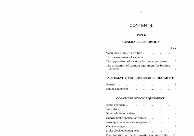
CONTENTS.Part I.
GENERAL DESCRIPTION.
Page
Vacuum-a simple definition ... ... ... ... 1
The measurement of vacuum... ... ... ... 1
The application of vacuum for power purposes ... 2
The utilization of vacuum equipment for brakingpurposes
...
...
...
...
...
...
2
AUTOMATIC VACUUM BRAKE EQUIPMENT.
General
...
...
...
...
...
...
...
3
Engine equipment
...
...
...
...
...
4
COACHING STOCK EQUIPMENT.
Brake cylinders ...
...
...
...
...
...
5
Ball valves
...
...
...
. ..
...
...
6
Direct admission valves
...
...
...
...
7
Guards' brake application valves
...
...
...
8
Passenger communication apparatus ...
...
...
8
Vacuum gauges ...
...
...
...
. ..
...
9
Brake block operating gear
. . .
...
...
... 10
The operation of the Automatic Vacuum Brake ... 11

vi
Part ILEXAMINATION AND TESTING OF
A.V.B. EQUIPMENT. PageExamination and adjustment ... ... ... ... 13Brake block adjustment ... ... . .. ... 13Use of clearance gauges (4- and 6-wheeled bogies) ... 13Handbrakes ... ... ... . . . ... ... 14Vacuum equipment . .. ... . .. ... ... 14Passenger communication apparatus ... ... ... 15Guards' emergency application valves ... ... 15Vacuum gauges ... ... ... . . . . .. ... 15Brake cylinder release valves ... . .. ... ... 15Adverse weather conditions-frost ... ... . . . 15Testing and irregularities
...
...
...
. ..
15
TEST APPARATUS.Irregularities and testing of A.V.B. equipment ... 16Engine equipment:-
(a) Engines fitted with combined large and smallejector
. ..
...
...
...
...
. . .
17(b) Engines fitted with single ejector and pump 17
Train equipment
...
...
...
...
...
18IRREGULARITIES, REMEDIAL ACTION.
Flexible hoses ... ... . .. ... ... ... 18D.A. valves . .. ... ... ... ... . .. 18Brake cylinders ... ... . .. ... ... ... 19Excessive vacuum in reservoirs
...
. . .
... 19
Dia. No.
DIAGRAMS.1. "U" tube for measurement of vacuum.2. General arrangement of vacuum brake on engine and
coaches.3. Vacuum hose coupling.4. Arrangement of vacuum brake cylinder.5. Ball valve.6. Direct admission valve.6a. Direct admission valve with modified air intake
shield.7. Emergency valve.7a. Emergency valve, modified type (standard).8. Communication valve (closed).8a. Communication valve (open).9. General arrangement of brake rigging on a modern
4-wheeled bogie.
vii
INDEX.
Part I.
Subject.
Page
Air, admission of, to train pipe ... ... 8,11Atmosphere, pressure exerted by ... . .. ... 2Brake, application, direct admission valves ... ... 7Brake application, time lag ... ... . .. ... 7Brake block, carrier beam ... ... ... ... 10Brake blocks ... ... ... ... ... 6,10Brake blocks, operating gear ... ... ... ... 10Brake, calculation of power ... ... ... ... 10Brake, continuous ... . .. ... ... ... 2,3Brake, continuous main vacuum train pipe... .. 3Brake cylinders, combined cylinder and reservoir... 5Brake cylinders, diaphragm type ... ... . .. 6Brake cylinder, pistons... ... ... ... . .. 5Brake cylinder, piston rods ... ... ... ... 6Brake cylinder piston rods, length of ... ... 6Brake cylinder piston rod gland packing ... ... 6Brake cylinder piston, rolling ring ... ... ... 5Brake cylinder, rolling ring type ... ... ... 5Brake, design of . .. ... ... ... ... 10Brake equipment, automatic vacuum ... ... 3Brake equipment, hand ... ... ... ... 4Brake, re-creation of vacuum after testing ... ... 11Brake, self-contained ... ... . .. ... ... 3Brake, testing after attaching or detaching vehicles... 11Brake, testing of ... ... ... ... ... 11Brake, automatic vacuum, operation of ... ... 11Brake valve, drivers' ... ... . .. ... ... 5Couplings, flexible hosepipe ... ... ... ... 3Cylinders, brake... ... ... ... ... ... 5Direct admission valves ... ... ... . . . 7Discs, passenger communication apparatus ... ... 9Driver's brake valve ... ... ... ... ... 5Dummy plugs ... ... . .. ... ... ... 3,4Ejector, combined type ... ... ... ... 4Ejector, large ... ... ... ... ... ... 4Ejector, small ... ... ... ... ... . .. 4Engine equipment, ejector ... ... ... . .. 4Engine equipment, vacuum pump ...
...
...
5
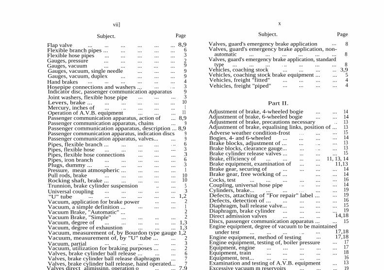
Subject.
Page
Flap valve ... ... ... ... ... ... 8,9Flexible branch pipes ... ... ... ... ... 6Flexible hose pipes ... ... ... ... ... 3Gauges, pressure ... ... ... ... ... 2Gauges, vacuum ... ... ... ... ... 9Gauges, vacuum, single needle ... ... ... 9Gauges, vacuum, duplex ... ... ... ... 9Hand brakes ... ... ... ... ... ... 4Hosepipe connections and washers ... ... . .. 3Indicator disc, passenger communication apparatus 9Joint washers, flexible hose pipe ... ... ... 3Levers, brake ... ... ... ... ... ... 10Mercury, inches of ... . .. ... ... ... 1Operation of A.V.B. equipment ... ... ... 11Passenger communication apparatus, action of ... 8,9Passenger communication apparatus, chains ... 9Passenger communication apparatus, description ... 8,9Passenger communication apparatus, indication discs 9Passenger communication apparatus, valves... ... 9Pipes, flexible branch ... ... ... ... . .. 6Pipes, flexible hose ... ... ... ... ... 3Pipes, flexible hose connections ... ... ... 3Pipes, iron branch ... ... ... ... ... 6Plugs, dummy ... ... ... ... ... ... 3Pressure, mean atmospheric ... ... ... ... 1Pull rods, brake ... ... ... ... ... 10Rocking shaft, brake ... ... ... ... ... 10Trunnion, brake cylinder suspension .. ... 5Universal coupling ... ... ... ... ... 3"U" tube ... ... ... ... ... ... 1,2Vacuum, application for brake power ... ... 2Vacuum, a simple definition ... ... ... ... 1Vacuum Brake, "Automatic" ... 2Vacuum Brake, "Simple" ... ... ... ... 2Vacuum, degree of ... ... ... ... ... 1,3Vacuum, degree of exhaustion ... ... ... 1,3Vacuum, measurement of, by Bourdon type gauge 1,2Vacuum, measurement of, by "U" tube ... ... 2Vacuum, partial ... ... ... ... ... 3Vacuum, utilization for braking purposes ... ... 2Valves, brake cylinder ball release ... ... ... 6Valves, brake cylinder ball release diaphragm ... 7Valves, brake cylinder ball release, hand operated... 7Valves direct alimissinn. operation o
...
... 7.9
Subject.
Page
Valves, guard's emergency brake application
...
8Valves, guard's emergency brake application, non-
automatic
...
...
...
...
...
...
8Valves, guard's emergency brake application, standard
type ... ... ... . .. ... ... ... 8Vehicles, coaching stock ... ... ... ... 3,9Vehicles, coaching stock brake equipment ... ... 5Vehicles, freight "fitted" ... ... ... ... 4Vehicles, freight "piped"
...
...
...
...
4
Part II.
Adjustment of brake, 4-wheeled bogie ... ... 14Adjustment of brake, 6-wheeled bogie ... ... 14Adjustment of brake, precautions necessary . . 13Adjustment of brake, equalising links, position of ... 13Adverse weather condition-frost . . . ... ... 15Bogies, 4- and 6-wheeled ... ... ... ... 14Brake blocks, adjustment of ... ... . .. ... 13Brake blocks, clearance gauge... ... . .. ... 13Brake cylinder release valves ... ... ... ... 15Brake, efficiency of ... ... ... ... 11, 13, 14Brake equipment, examination of ... ... 11,13Brake gear, securing of ... ... ... ... 14Brake gear, free working of ... ... ... 14Cocks, test ... ... ... ... ... ... 16Coupling, universal hose pipe . .. ... ... 14Cylinders, brake... ... ... . . . ... ... 19Defects, attaching of "For repair" label ... ... 19Defects, detection of ... ... ... ... ... 16Diaphragm, ball release valve... ... ... ... 15Diaphragm, brake cylinder ... ... ... ... 19Direct admission valves ... ... ... 14,18Discs, passenger communication apparatus ... ... 15Engine equipment, degree of vacuum to be maintained
under test ... ... ... . .. ... 17,18Engine equipment, method of testing ... 17,18Engine equipment, testing of, boiler pressure ... 17Equipment, engine ... ... ... ... ... 17Equipment, train ... ... ... ... ... 18Equipment, test... ... ... ... ... 16Examination and testing of A.V.B. equipment ... 13Excessive vacuum m reservoirs
...
...
... 19
vii] x

x
Subject.
Page
Flexible hose pipes ... ... ... ... ... 17Frost, releasing of brake blocks ... . .. ... 15Gauge, master vacuum... ... ... ... . .. 16Gauge, test cock . .. ... . . . . .. ... 16Gauges, vacuum examination of ... . .. ... 15Gland packing ... ... ... ... . . . 14,17Guard's emergency brake, examination of ... ... 15Hand brakes, examination and testing of ... ... 14Hose pipe coupling pins ... ... . .. ... 14Irregularities, action to be taken when engine found
correct ... ... ... ... ... . .. . . . 18Irregularities, causes of ... ... ... ... 16Irregularities, isolation of a defective diaphragm
cylinder
...
19Irregularities, isolation of a defective R.R. brake
cylinder ... ... ... . .. ... ... 19Irregularities on train, remedial action 18,19Irregularities, standard method of examination and
testing ... ... ... . .. ... ... 16,17Irregularities, sticking of brake cylinder piston ... 19Irregularities, testing of equipment ... ... ... 16Irregularities, testing of train equipment ... 18Joint washers, flexible hose pipe ... ... 14,17Leakages in brake equipment... ... ... ... 14Links, equalising ... ... ... ... ... 13Maintenance of brake equipment ... ... ... 13Mercury columns ... ... ... ... ... 16Passenger communication apparatus, periodic over-
haul ... ... . .. ... ... ... . .. 15Precautions, safety ... ... ... . . . 15,20Pump, vacuum ... ... . . . ... ... ... 17Release valves ... . .. ... . .. ... ... 15Release valves, cords and wires ... . .. ... 15Rods, piston, cleaning of ... ... . .. ... 14Rolling ring, brake cylinder ... ... . .. ... 19Safety precautions ... . .. ... ... 15,20Stops, equalising link ... . .. ... . .. ... 13Test apparatus ... ... ... ... ... ... 16Test apparatus, isolating cocks ... ... ... 16Test apparatus, leak discs ... ... ... ... 16Testing and irregularities ... ... ... ... 15Train equipment . .. ... ... . .. ... 18Triangular brake beams ... ... ... ... 14Universal hose pipe coupling ...
...
...
. .. 14
Subject.
Page
Use of brake block clearance gauge ... ... ... 13Vacuum equipment, air tightness of ... . .. 14Vacuum equipment, examination of ... . . . ... 14Vacuum gauges, examination of ... ... ... 15Vacuum, over creation of ... ... . .. . .. 19Washers, valve seating ...
. ..
...
...
. ..
15
xi
THE AUTOMATIC VACUUMBRAKE.
Part I.
GENERAL DESCRIPTION.
Vacuum, a simple definition.A vacuum is a space absolutely devoid of any matter
capable of exerting pressure; in other words, a truly emptyspace.
For everyday purposes it is not possible to obtain aperfect vacuum, because, although there is no difficultyin making a vessel which is capable of withstanding theexternal pressure of the atmosphere after a vacuum hasbeen created inside the vessel, there is no means of exhaust-ing the vessel completely, and a little of the air, or whatevergas the vessel contained, is always left behind.
The measurement of vacuum.For experimental or test purposes, a special type of
gauge is used, and this consists of a "U"-shaped tubecontaining mercury (see Diagram No. 1). It will beappreciated that if air is withdrawn from one leg of thetube, the pressure of air in the other leg of the tube willforce the mercury down in that leg and it will flow up theleg from which the air has been taken. Therefore, theheight to which the column of mercury rises in the "ex-hausted" leg of the tube will reveal the extent to whicha vacuum has been created.
The principle upon which the measurement of vacuumis based, therefore, is that at the mean atmospheric pressureof 14.7 lb. per sq. in ., a column of mercury 30" high isbalanced in the "U" tube when an almost perfect vacuumis obtained on the "exhausted" leg of the tube.
Accordingly, it is usual to refer to the measurement ofvacuum in inches, and all industrial vacuum gauges arecalibrated to read in "inches of mercury". It is also usualto use a figure of 15 lb. per sq. in . in referring to atmos-pheric pressure for all practical purposes.
For industrial purposes it is, of course, impossible touse the "U" tube as a means of measuring vacuum, and
1

2instead, gauges of the "Bourdon" type are used. Inappearance and construction, these resemble the familiardesigns of pressure gauge, but are arranged to operateunder conditions opposite to those under which a pressuregauge is used. From an industrial point of view, "Bourdon"gauges give a high degree of accuracy and reliability.
The application of vacuum for power purposes.From what has been said in the previous paragraphs, it
will be seen that a pressure of 15 lb. per sq. in . will supporta column of mercury 30" high in a "U" tube. Therefore,a pressure of 10 lb. per sq. in. would support a column 20"high, and, in other words, every inch of vacuum is equalto a pressure of J lb. per sq. in .
Therefore, if we take a cylinder or tube and fit insideit a movable piston and then exhaust the air from oneend of the cylinder until 20" of vacuum is achieved, theatmosphere in the other end of the cylinder will exert apressure of 10 lb. on every sq. inch of the piston's surface,and, assuming that the piston is free to move easily alongthe cylinder, it will be seen that by connecting the pistonto suitable levers the power exerted by the atmospherecan be utilised, and all modern vacuum brake cylindersembody this principle.
The utilisation of vacuum equipment for brakingpurposes.
The utilisation of vacuum was early recognised as beinga convenient method of securing power for the operationof a continuous brake on railway vehicles.
In the original designs, a vacuum was created in thebrake equipment when it was desired to apply the brake,and the system was known as the "Simple Vacuum"system. This system had many disadvantages, however,not the least of which was the time required to createsufficient vacuum to apply the brake, and in the course oftime the system was devised which is now known as the"Automatic Vacuum Brake". This system is used on themajority of steam trains in Great Britain and is also widelyused on trains in many other parts of the world.
The Automatic Vacuum Brake has many advantagesover the early Simple Vacuum Brake, and perhaps themost important of these advantages is that in the event ofdamage to any of the vacuum equipment, or upon a trainbecoming divided, the brake is automatically appliedthroughout the train.
3This is due to the fact that in the Automatic VacuumBrake system, a vacuum is created and maintained in orderto release the brake, and the admission of air to the equip-ment after the vacuum has been created, causes the braketo be applied with a force proportional to the amount ofair admitted.
The degree of vacuum upon which the design andoperation of the Automatic Vacuum Brake is based is apartial vacuum equal to 20" of mercury, and the L.M.S.Company's regulations provide that in the operation ofthe equipment the vacuum created must show a reading ofnot less than 19" nor more than 21" on the engine vacuumgauge, and not less than 17" on the gauge in the rearbrake van or brake compartment of the train.
Automatic Vacuum Brake equipment.
General.
The brake is required to be continuous throughout alltrains composed of coaching stock, engines and tenders,and all vehicles comprising the train are fitted with a maintrain pipe, to which flexible pipes and universal couplingswith joint washers are attached to enable vehicles to becoupled and uncoupled and to allow for the relativemovement of the vehicles when running.
After a train has been made up, and the pipes betweenthe vehicles connected, the train pipe as a whole has, ofcourse, to be made air-tight, and for this purpose a dummyplug is provided on each end of each vehicle (with theexception of the intermediate positions on certain coupledset trains composed of old type vehicles), so that theflexible pipes on the front end of the engine and the endof the last vehicle can be sealed off.
Figure 2 shows the general arrangement of vacuumbrake equipment on an engine and coaches, and Figure 3shows a flexible hose pipe coupling and joint washer.
The degree of exhaustion, or vacuum, required tooperate the Automatic Vacuum Brake on steam trains iscreated by a steam ejector on the engine, and althoughejectors may differ in design on the various railways, theprinciple is identical.
All coaching stock vehicles are fitted with a self-containedbrake, but freight vehicles are not always so fitted. Inorder to make the difference in vehicles clear, therefore,the following definitions are given:-
4Freight stock.
"Fitted vehicles" A `'fitted" vehicle must be understoodto be a vehicle which carries its ownbrake equipment and in which thebrake blocks are operated by theAutomatic Vacuum Brake system.
"Piped vehicles" A "piped" vehicle must be under-stood to be a vehicle which is fittedonly with a continuous pipe from endto end, and in which the brake blocksare operated only by hand levers.
It will be understood that in certain types of freighttrains only a certain number of vehicles are required tohave vacuum controlled brake gear, but in order to makethe main train pipe continuous throughout the train it isnecessary for all the vehicles in the train to have a trainpipe, flexible connections and dummy plugs.
Under normal conditions, a reduction in vacuum of 5"is sufficient to apply the brake, and the driver's brakevalve on the engine is designed to allow a controlledadmission of air to the train pipe and so permit sensitivecontrol of the braking of a train.
A full opening of either the driver's or guard's brakevalve results in the vacuum in the train pipe being totallydestroyed and gives the maximum braking effect in aminimum of time.
,Engine equipment.
The type of ejector most commonly used is the combinedtype which combines a large and a small ejector. Theseejectors work independently of each other and are designedto create and maintain the required vacuum in the brakeequipment with a minimum consumption of steam.
The large ejector is powerful and creates a vacuumquickly, but uses a lot of steam. It is used, therefore, toensure rapid creation of vacuum prior to starting a train,or after an application of the brake. The small ejector, onthe other hand, is designed to overcome the small leakageswhich are inevitable in a system having numerous valvesand flexible connections, and ensures that the degree ofvacuum required is maintained whilst using a minimumamount of steam. The small ejector is kept in operationso long as control of the brake equipment is required.
5Certain ex L.N.W.R. engines and certain engines
belonging to other Companies are fitted with a vacuumpump and a single ejector, the purpose of the pump beingto maintain vacuum in the brake equipment so long as thetrain is running.
A vacuum gauge is provided on every engine, and recordsthe degree of vacuum in the train pipe, and a driver'sbrake valve is fitted which regulates the admission of airto the train pipe and enables the driver to control theapplication of the brake throughout a train with a highdegree of sensitiveness.
Coaching stock equipment.
Brake cylinders.
Four-wheeled bogie vehicles are fitted with two 18"diameter brake cylinders of the type shown in Figure 4.This type of cylinder combines the cylinder and reservoirin a common outer casing.
Six-wheeled bogie vehicles differ somewhat in design,in that the brake cylinder and reservoir are separate unitsconnected together by suitable piping. The principle ofoperation, however, is identical with that of the combinedtype of cylinder.
On the outer case of each type of cylinder are attachedtwo pivots or trunnions, which allow the cylinder to besuspended in suitable brackets attached to the vehicleunderframe. This arrangement allows the cylinder toswing in a small arc, and ensures that the piston rod remainsin line with the cylinder throughout the range of its move-ment, and is not subjected to any bending forces as wouldbe the case if the cylinder were rigidly fixed.
The piston, which has a deep head, fits easily in thecylinder, and the piston head is recessed at the top andbottom to contain a rubber ring. This ring is known asthe rolling ring and serves the same purpose as the pistonrings of a steam or gas engine piston. As the piston movesup or down in the cylinder, the ring rolls between thepiston and the cylinder wall, and being compressed firmlybetween the two, prevents air passing from one side of thepiston to the other. The recesses at the top and bottomof the piston head are provided to prevent the rolling ringfrom getting out of alignment and causing the pistonto stick in the cylinder.

6The piston rod is fastened to the piston head, and at
its lower end it is connected by means of a pin to thelever mechanism which operates the brake blocks. Inpassing through the cylinder casing, the rod is surroundedby a rubber packing gland, the purpose of which is toprevent air entering the cylinder at this point, whilst atthe same time permitting the piston rod to move in andout of the cylinder.
The diagram, Figure 4, shows the piston in the "Brakeon" position, and it should be noted that when the "Brakeoff" position is reached, the measurement from the packinggland to the boss end of the piston rod is 82".
Occasionally the older types of vehicle may be foundto be fitted with a diaphragm type of cylinder. This typediffers from the "rolling ring" type in that a rubberdiaphragm is used instead of a rolling ring to seal off oneside from the other. The principle of operation, however,is not altered.
Ball valves.
Fitted to the bottom of each cylinder and connectingthe cylinder to the train pipe by means of an iron branchpipe and a small flexible hose, is a ball valve of the typeshown in Figure 5. This valve is one of the most importantfittings in the whole of the equipment, as its purpose isto control the passage of air to and from the reservoirportion of the brake cylinder.
The passages in the valve body are so arranged that theunderside of the cylinder is always in communication withthe train pipe, whilst the reservoir portion of the cylinderis open to the train pipe only when the ball is unseated.So long as the ball is pressed on to its seat, therefore, thereservoir portion of the cylinder is isolated from the trainpipe.
Reference to Figure 4 will show that when air is with-drawn from the train pipe by the engine ejector, any airin the reservoir portion of the cylinder will flow past theball into the train pipe until an equal vacuum exists oneach side of the piston. The ball will remain unseated solong as this equality of vacuum exists, but as soon as airis again admitted to the train pipe it will enter the ballchamber and press the valve firmly on to its seat, therebysealing off the reservoir portion of the cylinder and main-taining the vacuum which exists there.
7The automatic action of the ball valve continues in this
way so long as the brake equipment is under vacuumoperation, but circumstances arise in which it is necessaryto have a hand-operated means of equalising the conditionson each side of the brake piston. For instance, when atrain is detached from an engine, the vacuum in the trainpipe is completely destroyed, but by the action of all theball valves in the train the vacuum in the reservoir portionsof the brake cylinder is maintained, and so long as thisvacuum remains the brake will remain "on" throughoutthe train.
Embodied in the ball valve casting, therefore, is a slidingcage in which the ball is contained, and the outer end ofthis cage is connected to a cross lever. The action ofpulling this lever pulls the cage outward, and this in turnpulls the ball off its seat. Air then flows into the reservoirportion of the cylinder until conditions are again equal onboth sides of the piston, and the piston falls under its ownweight to the bottom of the cylinder and the brake isreleased.
In order that this release action may be carried outfrom the side of the coach, a wire or cord is taken fromeach side of the coach to one end of the cross lever, andto ensure that the cage returns to its normal position whenvacuum operation is resumed, a diaphragm is connectedto the cage. This diaphragm forms an air-tight glandwhere the cage spindle passes through the body of theball valve, and as it is open to the atmosphere on theoutside, any withdrawal of air from the ball valve interiorcauses the atmospheric pressure on the outside of thediaphragm to move the diaphragm inwards, thus returningthe cage to its normal position.
Direct admission valves.From time to time devices have been patented for
accelerating the speed with which vacuum is destroyed,thereby reducing the time lag in the brake applicationbetween the front and the rear of long trains.
The valve adopted for this purpose by the L.M.S.R.is the Direct Admission Valve, which is shown diagram-matically in Figure 4, and in detail in Figures 6 and 6a.
The principle employed is that air entering the trainpipe simply actuates the D.A. valve, and does not enterthe brake cylinder, so that in effect each cylinder has anindependent air supply and the operation of the brakegear as a whole is speeded up in consequence.
8The manner in which the D.A. valve operates is as
follows:-In the creation of a vacuum in the brake equipment,
air is drawn from the cylinder, through passage C2, pastnon-return Valve "A" into the train pipe. At the sametime air is extracted from chamber "B" past the flats "D"on the spindle until equal vacuum exists in chamber "B"and in the train pipe.
Upon the reduction of the vacuum in the train pipe bythe admission of air to the pipe, the diaphragm "E" israised by reason of the higher degree of vacuum existingin chamber "B", and as the rising diaphragm carries withit the spindle, valve "F" is pushed open and admits airto the underside of the brake cylinder through passage"C1". When sufficient air has been admitted to reducethe vacuum in the cylinder, and, therefore, in passages"C1" and "C2", to the level of that in the train pipe, thediaphragm "E", being again in equilibrium, is restoredto its original position by the spring "G", and valve "F"closes and prevents further flow of air to the cylinder.
In the event of a D.A. valve requiring to be isolated,this can be achieved by reversing the cap "H" as shownin Figures 6 and 6a.
Guard's brake application valves.To enable the guard of a train to apply the Automatic
Vacuum Brake in case of emergency, a special guard's
brake valve is provided in all passenger brake vans and brake compartments. The valve is not a graduable valve,in other words the lifting of the valve lever brings abouta full application of the brake and no partial applicationof the brake is possible as is the case with the driver'sbrake valve on the engine.
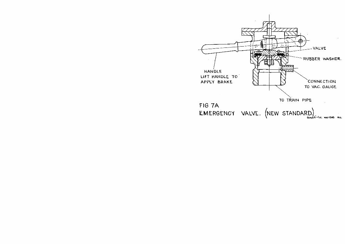
The type of valve shown in Figure 7 was used originallyand contained automatic features. The majority of thistype have, however, now been rendered non-automaticand are marked "N.N." to denote this. The vacuumchamber which is shown does not now serve any usefulpurpose.
The type of valve shown in Figure 7a has now beenadopted as the standard valve, and as the diagram showsit consists of a simple lever-operated flap valve.
Passenger communication apparatus.Emergency communication apparatus is fitted to all
passenger-carrying vehicles, and is as shown in Figures 8and 8a.
9' he apparatus consists of a small diameter branch pipe
connected at one end to the train pipe, and having at theother end a small flap valve. A horizontal shaft, suitablysupported at each end, passes through the valve casing,and a cam is attached to the shaft in such a manner thata partial rotation of the shaft causes the cam to lift theflap valve into its "open" position.
A continuous chain passes through the full length ofthe coach, and a small portion of this chain is madeaccessible in each compartment, and as the end of thechain is connected to the cross shaft previously mentioned,the action of pulling the chain at any point causes rotationof the cross shaft and so operates the flap valve. Thevalve is so designed that the amount of air admitted tothe train pipe by the opening of the valve is sufficient tocause only a gradual application of the brake, and this,together with the resultant drop in the vacuum registeredby the engine and brake compartment vacuum gauges isan indication to the driver and guard that something isamiss which calls for the train to be stopped.
In order to give a clear indication of the vehicle in whichthe chain has been pulled, the cross shaft which operatesthe valve is provided with a disc at each end. Normally,these discs lie in the horizontal position, but when theshaft is operated it turns through an angle of 90°, and thediscs accordingly assume a vertical position and enablethe affected coach to be found easily.
Vacuum gauges.
All passenger brake vans and brake compartments arefitted with a vacuum gauge in order that a guard may seeat all times that the degree of vacuum called for underthe Company's regulations has been created and ismaintained.
Many of these gauges are of the Duplex type, that is,they have the dual function of recording the degree ofvacuum in the reservoir side as well as that in the trainpipe. It should be noted, however, that the needle marked"Reservoir" only indicates the vacuum existing in thereservoir side of the cylinder to which it is connected; itdoes not indicate the conditions in the reservoirs of theother cylinders in the train.
A single needle type of gauge only records the degreeof vacuum existing in the main train pipe.

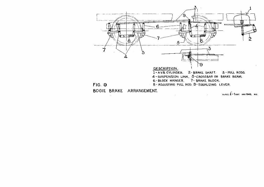
10Brake block operating gear.
Figure 9 shows the general arrangement of the brakerigging on a modern 4-wheeled bogie, and although thediagram shows one bogie only, the rigging on the bogieat the other end of the coach is identical.
The power obtainable from the brake cylinder istransmitted through the rocking shaft to the main pullrod, and this main pull rod is in turn connected to a seriesof levers which operate the beams on which the brakeblocks are mounted.
The levers are arranged so that in addition to trans-mitting power from the brake cylinder, they equalise thepower applied to the brake blocks so that each block isapplied to the wheel with equal force. Adjustment isprovided in the link connecting the vertical levers bymeans of a series of holes which permit a graduatedvariation in the distance between the pins connecting thelink to the vertical levers.
In designing a railway coach it is the aim to allowsufficient braking power to brake the vehicle efficientlywithout giving too severe, or too gradual a retardingeffect, and experience has shown that the most satisfactoryarrangement is that which gives a brake power equal to75 to 80 per cent. of the weight of the vehicle. Thus, ina coach weighing 30 tons, a brake power of 22 to 24 tonsis provided for in designing the brake equipment.
It was shown on page 2 that with a partial vacuumequal to 20" of mercury in the reservoir side of a brakecylinder, a pressure of 10 lb. per sq. inch is obtained onthe side of the piston which is under atmospheric pressure.With an 18" diameter cylinder, therefore, the total pressureon the piston under these conditions will be:-
10 lbs. x total area of pistonwhich equals 10 lbs. x 254.5 sq. in .
= 2,545 lbs. pressure on piston.By making the rocking shaft, to which the piston is
coupled, so that a 2 to 1 leverage is obtained, this figureof 2,545 is doubled at the short arm of the rocking shaft,and by coupling the main pull rod to the short arm, apull of 2 x 2,545 lbs. = 5,090 lbs. is obtained in themain pull rod.
The system of levers between the main pull rod andthe brake block beams then multiplies this force evenfurther, until the total of the forces on the sixteen brakeblocks is equal to 22 to 24 tons
11The operation of the Automatic Vacuum Brake.
Before a train commences its journey, the operation ofthe vacuum equipment must be tested, and whilst thefollowing describes L.M.S.R. practice and may differslightly in detail from the practice of other Companies,the general principles are identical.
First, the engine is tested as an independent unit beforeit leaves the shed, and it is the duty of the driver to ensurethat the vacuum equipment is in good working order.
Subsequently, when the engine has been coupled to atrain, the train pipe flexible hoses between vehicles coupled,and the flexible hose at the end of the last vehicle correctlyseated on the stopper, the driver admits steam to the engineejector and exhaustion of the vacuum equipment through-out the train commences.
This action releases the brake throughout the train, andthe guard must observe the vacuum gauge in the brakecompartment until a reading of at least 17" is noted. Hemust then lift the handle of the emergency brake valve,thus applying the brake throughout the train, and afterreturning the valve to the closed position again must watchthe vacuum gauge whilst vacuum is being restored untilthe reading is again not less than 17".
This test must also be carried out whenever a vehicleis detached from a train, or when an additional vehicle isattached to a train, and in fact it should be the practiceto carry out the test whenever train pipe flexible hosesare disconnected for any purpose.
The test completed satisfactorily, the train is ready toproceed, and the requisite vacuum having been created, asdescribed above, to release the brake, the application ofthe brake is now normally under the control of the enginedriver.

13
Part H.
EXAMINATION AND TESTING OFA.V.B. EQUIPMENT.
Examination and adjustment.The trouble-free operation of A.V.B. equipment on
coaching and freight stock depends upon careful examina-tion and maintenance of the equipment. It is essential,therefore, that trains or loose vehicles which are placedin carriage sidings and are left under the control of theAutomatic Vacuum Brake should be examined uponarrival, and particular attention directed to the followingpoints:-
Brake block adjustment.The state of adjustment of the brake blocks must allow
the maximum stroke of the brake piston to be available.The efficiency of the gear is dependent upon its beingadjusted as closely as possible to the limit allowed, asotherwise much of the power available in the brake cylinderis lost before the brake blocks come into contact withthe wheels.
Any brake blocks which have worn down to scrappingsize must, of course, be replaced without delay.
Use of clearance gauges.Before the clearance between brake blocks and wheels
can be checked, the brake must be fully released, i.e. thebrake piston must be in its lowest position, and whereequalising links are fitted, these should be close up tothe stops.
Steps must, of course, be taken to prevent vehiclesmoving in either direction when the brake has beenreleased

144-wheeled bogie.
The brake block adjustment on 4-wheeled bogies shouldallow free movement of the I" gauge between the brakeblocks and wheels. In the case of vehicles having thelong and short arm type of triangular brake beam, thegauge should be inserted on the "long" arm side; on othertypes it is immaterial on which side the gauge is used.
6-wheeled bogie.The adjustment of brake blocks on a 6-wheeled bogie
requires the use of two gauges which must be insertedbetween the brake blocks and tyres of two wheels.
Care must be taken in the examination or adjustmentof brake gear to ensure that the gear as a whole worksfreely, that all portions of the gear are properly securedand that the legs of all split cotters are well opened.
Hand brakes.The hand brake on all vehicles so fitted must be examined
and tried as vehicles come to hand at carriage depots orfreight sidings, to ensure that the brake is properlyworkable. If found to be in need of adjustment, theadjustment must be carried out before the vehicle is againallowed into traffic.
Vacuum equipment.In the examination of vehicles standing under control
of the Automatic Vacuum Brake, attention must bedirected to the air-tightness of the equipment and anytendency to "leak-off" noted. Particular attention shouldbe paid to piston rod glands and D.A. valves.
When opportunity permits, brake piston rods whichare not protected by flexible stockings should be cleanedwith dry spun yarn. Under no circumstances, however,must any abrasive cleaning compound be used on the spunyarn.
Flexible hoses and branch pipes should be examinedfor such defects as worn hoses, defective or damagedcouplings or defective joint washers. The clips securingflexible hoses to couplings and train pipes should beexamined and left secure and in contact with the hosethroughout the circumference. Any clips having a damagedtongue must be changed, and the coupling pins and chainsmust be left in good condition.
15Passenger communication apparatus.
At monthly intervals the passenger communicationapparatus must be operated to ensure that the apparatusworks freely, and all parts must be left in a clean conditionand in good working order. Any worn, hardened, orotherwise defective valve seating washers must be changedand defective chains renewed.
Guards' emergency application valves.
Guards' emergency valves must be tried to ensure thatthey operate freely and that the valve seating washer is ingood condition.
Vacuum gauges.Vacuum gauges must be examined for such visible
defects as loose connections, bent needles, broken glassesor bent or defaced dials, and when tested under vacuum,care must be taken to see they are registering correctly.
Brake cylinder release valves.Release valves having defective cords or wires, or
showing any sign of diaphragms leaking, should be notedand attention given.
Adverse weather conditions-frost.
Whenever severe frost is anticipated, steps must be takento prevent the brake blocks of vehicles stabled in exposedpositions from becoming frozen to the wheels.
Brakes must, therefore, be released by operating therelease valves, but care must be taken to ensure that thevehicles are properly secured and are unable to move inany direction which might result in their fouling otherroads.
Testing and irregularities.Every effort should be made to test the brake equipment
on vehicles before they are brought into use in order thatirregularities in the operation of the equipment or leakagesmay be located and rectified.

16Test apparatus.
The standard apparatus for testing A.V.B. equipmentconsists of:-
(a) Leak discs, for testing the efficiency of the engineejector.
These are circular discs having either a -&" orv" diameter hole in the centre, and their overalldiameter is such that they will cover the open endof the flexible hose coupling which is shown inFigure 3.
(b) Isolating cocks for isolating portions of the A.V.B.equipment and recording the degree of vacuumexisting.
These cocks have a standard flexible hosecoupling of the type shown in Figure 3 at eitherend, and can, therefore, be used to connect theflexible hoses between an engine and train orbetween vehicles, or can be used in connectionwith a leak disc.
As the cocks embody a vacuum gauge, they can be used:- (1) To test the ejector equipment on the engine.(2) To isolate the train pipe on a train after the engine
has created a vacuum and to show what vacuumis maintained after isolation of the train pipe.
(3) To test conditions on the engine and train whencoupled together.
Test cocks must be carefully handled to avoid damageto the gauges, and the cocks must be periodically testedin accordance with instructions against a master vacuumgauge or mercury column to ensure that they are in goodworking order and their gauges registering correctly.
Irregularities-testing of equipment.The failure of an engine to create and maintain the
regulation degree of vacuum throughout a train may bedue to one or more of the following defects:-
(1) Front flexible hose on engine or rear flexible hoseon train not seated correctly on stopper.
(2) Leakage in flexible hose couplings between vehicles.
(3) Passenger communication valve or valves partlyopen.
17
(4) Leakage at brake cylinder piston rod gland packings.(5) Leakage at brake cylinder release valves, D.A.
valves, guards' emergency valve, or joint washers.During examination of a train, steps must, whenever
necessary, be taken to determine whether the vacuumgauge in the rear brake or brake compartment is register-ing correctly.
It may occur, however, that the defect cannot be locatedduring examination, and the action to be taken by theC. & W. examiner in these circumstances is as follows:-
1. -Engine equipment (failure to create the requisiteamount of vacuum throughout a train).
If the cause of the trouble cannot be located duringexamination of the train, the examiner must first ascertainthat the boiler pressure is within 10 lbs. of the workingpressure, and the actual pressure indicated by the boilerpressure gauge must be noted by the examiner and thedriver.
Accompanied by the fireman, the examiner must thenmake a leak disc test in the following manner:-
(a) Engines fitted with combined large and small ejector.Uncouple the engine or tender flexible hose from
the train and couple this hose to the isolating cock.Place a -&"leak discover the open end of the isolatingcock and hold this in position.
The driver must then create 20"-21" of vacuumwith the large ejector and must maintain this degreeof vacuum with the small ejector only.
This must be recorded by the vacuum gaugeattached to the isolating cock, and if no difficultyis experienced in maintaining 20'-21" of vacuumas stipulated, the engine is not at fault.
(b) Engines fitted with a single ejector and a vacuumPump.
Proceed as in (a), but use a 4" leak disc.The driver must then create 20"-21" of vacuum
with the ejector, and if this is recorded on thegauge attached to the isolating cock and can bemaintained without difficulty, the engine is not atfault.
No test of the vacuum pump is required, as this comesinto operation only when the engine is running.

isIf an isolating cock is not available the foregoing tests
can be made using the leak discs only. In this case thediscs should be applied direct to the coupling of the engineor tender flexible hose, and the degree of vacuum obtainedshould be observed from the vacuum gauge on the engineand noted by both the examiner and the driver.
If the engine is unable to fulfil the conditions stipulatedand is, therefore, at fault, the Station Master must takesteps to have the fault remedied or to have another engineprovided.
If some time is likely to elapse before an engine isavailable, steps should be taken by the Station Master,during the waiting period, to have tests continued through-out the train by using any suitable engine which may beavailable, as cases have occurred where both engine andtrain have been at fault; such further tests should, wheneverpracticable, be made from the leading end of the train.
2.-Train equipment.Having ascertained that the engine equipment is satis-
factory and the train equipment at fault, the examinermust proceed to test the train in the following manner:-
Couple the engine or tender flexible hose to the trainflexible hose with the isolating cock inserted between thetwo hoses.
Use the engine ejector to create a vacuum of 20"-21", asindicated by the isolating cock gauge, and then turn thecock so that the train is isolated from the engine.
If the gauge needle falls rapidly, indicating a leakagein the train equipment, repeat the test process betweenvehicles, in groups of three or four vehicles, until thedefect is located.
Irregularities-remedial action.Flexible hoses.-Defective flexible hoses, whatever the
defect, should be replaced, and care must be taken in fittingthe replacement hose to see that the clip is in contact withthe hose throughout its circumference and the tongue notin any way distorted.
D.A. valves.D.A. valves found to be defective should be blanked
off by removing the top wing nut and cap, placing an oldrepair card slightly smeared with oil on top of the valve,and replacing the cap in the reverse position, finallyscrewing down the wing nut securely.
19$rake cylinders.
Should a "rolling ring" type of brake cylinder be foundto be defective, the flexible branch pipe from the ballvalve to the D.A. valve should be disconnected at theball valve and the pipe plugged on the train pipe side withthe special type of plug which is provided for the purpose.
The defective cylinder should then be equalised bypulling the release wire to the ball valve and holding thisuntil all vacuum existing in the cylinder has been destroyed.
Where a brake piston sticks in the cylinder it is notdesirable to uncouple the piston rod, and the action out-lined above will generally suffice. Should the piston beheld fast with the brake hard on, however, and cannotbe moved towards the "off" position, the piston must bedisconnected from the rocking shaft by removing theconnecting pin.
When such action is taken, the cylinder must beprevented from turning over by securing it suitably throughthe piston rod pin-hole.
The long arm of the rocking shaft must also be securedso that it cannot fall downward and foul the permanentway. Steps must also be taken to see that the brake blocksaffected are left clear of the wheels, and that the wheelshave not sustained any damage through prolonged brakingor skidding which would result in the vehicle being unfitfor traffic.
In the event of a diaphragm type of cylinder being foundto he defective, it should be isolated by disconnecting thebranch pipe and inserting a suitable plug to render thetrain pipe air-tight.
It should be understood that in all the foregoing cases,or whenever any action is taken to temporarily isolateor render ineffective any part of the vacuum equipment ofa vehicle, a "for repair" card must be attached to eachside of the vehicle concerned before it is allowed forward,and a comprehensive repair must be made at the earliestopportunity.
Excessive vacuum in reservoirs.It may occur that upon an engine being coupled to a
train, the creation of 20"-21" of vacuum does not fullyrelease the brake. This is due to the fact that the enginepreviously attached to the train created more than 21"of vacuum, and the reservoir portions of all the cylinders

20are therefore left with more than the stipulated degree ofvacuum, and do not balance with the 20"-21" created bythe second engine when the latter is connected to thetrain pipe.
In these circumstances, equilibrium must be restoredin all the cylinders of the train by operating each releasevalve in succession, and when this has been done, re-creating vacuum throughout the equipment in the normalway.
Safety precautions.The attention of all concerned is directed to the necessity
of complying with the Company's regulations for theprotection of staff working on carriages and wagons,E.R.O. 10444 and 10445, whenever called upon to effectany repair or adjustment, etc., to the Automatic Vacuumor Hand Brake on either coaching or freight stock.