long-endurance sensing and mapping using a hand-launchable
TRANSCRIPT
Research Collection
Conference Paper
Long-Endurance Sensing and Mapping using a Hand-LaunchableSolar-Powered UAV
Author(s): Oettershagen, Philipp; Stastny, Thomas; Mantel, Thomas; Melzer, Amir; Rudin, Konrad; Gohl, Pascal;Agamennoni, Gabriel; Alexis, Kostas; Siegwart, Roland Y.
Publication Date: 2016
Permanent Link: https://doi.org/10.3929/ethz-a-010585180
Originally published in: Springer Tracts in Advanced Robotics 113, http://doi.org/10.1007/978-3-319-27702-8_29
Rights / License: In Copyright - Non-Commercial Use Permitted
This page was generated automatically upon download from the ETH Zurich Research Collection. For moreinformation please consult the Terms of use.
ETH Library

Long-Endurance Sensing and Mapping using aHand-Launchable Solar-Powered UAV
Philipp Oettershagen, Thomas Stastny, Thomas Mantel, Amir Melzer, KonradRudin, Pascal Gohl, Gabriel Agamennoni, Kostas Alexis, and Roland Siegwart
Abstract This paper investigates and demonstrates the potential for very long en-durance autonomous aerial sensing and mapping applications with AtlantikSolar, asmall–sized, hand–launchable, solar–powered fixed–wing unmanned aerial vehicle.The platform design as well as the on–board state estimation, control and path–planning algorithms are overviewed. A versatile sensor payload integrating a multi–camera sensing system, extended on–board processing and high–bandwidth com-munication with the ground is developed. Extensive field experiments are providedincluding publicly demonstrated field–trials for search–and–rescue applications andlong–term mapping applications. An endurance analysis shows that AtlantikSolarcan provide full-daylight operation and a minimum flight endurance of 8 hoursthroughout the whole year with its full multi-camera mapping payload. An opendataset with both raw and processed data is released and accompanies this papercontribution.
1 Introduction
The field of aerial robotics has seen rapid growth in the last decade. Prerequisitetechnologies have developed to the point that we are not far from the day whenutilization of aerial robots is prevalent in our society. With an application rangethat includes infrastructure inspection [13], surveillance for security tasks [6], dis-aster relief [25, 8], crop monitoring [7], mapping [1], and more, Unmanned AerialVehicles (UAVs) already provide added value to several critical and financially sig-nificant applications, and are widely acknowledged for their potential to achieve alarge impact in terms of development and growth. Examples of compelling existinguse–cases include the mapping of the Colorado flood area in 2003 [4], the 3D recon-struction of the “Christ the Redeemer” statue in Brazil and the Matterhorn mountain
Autonomous Systems Lab, ETH Zurich, Switzerland, e-mail: [email protected]
1

2 P. Oettershagen et al.
reconstruction [20], and the live offshore flare inspection that took place in the NorthSea [3].
While these are impressive achievements, there are still major factors that limitthe applicability of UAVs. One such factor is their relatively low endurance. Indeed,long-endurance flight capabilities are crucial for applications such as large-scaleSearch–and–Rescue support, industrial pipeline monitoring, atmospheric research,offshore inspection, precision agriculture and wildlife monitoring. This new class ofproblems exposes a practical limitation in the majority of currently available aerialrobot configurations.
Solar–powered flight is a key enabling technology for long-endurance operations.By harnessing the suns energy and storing solar power during the day, flight timescan be significantly prolonged. In cases of extreme designs, sustained flight caneven be achieved through night time and/or cloudy conditions. An existing exampleof extreme endurance is the QinetiQ Zephyr UAV (22m wingspan), which brokerecords, sustaining flight for two weeks [24]. However, scaling down from the high-altitude ”pseudo satellite” class to more manageable, rapidly deployable and low-altitude designs is not trivial.
Fig. 1 The AtlantikSolar UAV is capable of very long–endurance operation in missions includingmapping, surveillance, victim detection and infrastructure inspection.
Motivated by the increasing industrial, scientific and societal demand for per-sistent automatic aerial sensing and surveillance, long–endurance, solar–poweredfixed–wing aircrafts have been a research priority in the Autonomous Systems Lab(ASL) at ETH Zurich. With the most recent development being the AtlantikSolarUAV, our aim is to extend the current technological state of the art with a robust

Long-Endurance Sensing and Mapping using a Hand-Launchable Solar-Powered UAV 3
and versatile platform capable of significantly longer term sensing and mappingon the order of days or even weeks. Fig. 1 depicts the AtlantikSolar UAV and itssensing capabilities. The detailed design of this UAV platform has been describedin [18]. This paper extends our previous design-oriented work by investigating andcharacterizing possible application scenarios for our platform. More specifically, wepresent a set of field trials that are enabled by a diverse sensor payload recently in-tegrated into the UAV. This on–board sensor payload includes RGB and grayscalecamera systems and a thermal vision sensor in combination with a complete suiteof sensors that enable the vehicle to navigate autonomously.
The remainder of this paper is organized as follows: We present a description ofthe AtlantikSolar vehicle in Section 2, its sensing and mapping capabilities in Sec-tion 3, field experiment results in Section 4, and derived conclusions in Section 5.We also provide a detailed discussion of our experiences from both search–and–rescue as well as mapping missions, and release a dataset containing raw as well aspost–processed data.
2 AtlantikSolar Unmanned Aerial Vehicle
2.1 Platform Overview
RCwReceiverwKRCwMultiplexer
MainwTelemetryReceiver
GPS
MotorwKGearbox
ESC
IMU
Autopilot
BatterywPack
PowerwBoard
TemperaturewSensor PressurewSensorswOandwpitotwtubesL
Batteries
CarbonwFibrewSpar
KelvarwSupportedSolar-modules
Ribs
OracoverFoilwSkin
KevlarLeading
Edge
WingwMountedSensorwPod
Fig. 2 AtlantikSolar system overview.
The AtlantikSolar UAV (Fig. 2, Table 1) is a small-sized, hand-launchable,low-altitude long-endurance (LALE), solar-powered UAV optimized for large-scaleaerial mapping and inspection applications. A detailed overview of the conceptualdesign of AtlantikSolar is given in [18]. The design methodology is based on thework in [16, 10] with extensions on optimizing solar-powered UAVs for a range ofdeteriorated meteorological conditions (e.g. cloud obstruction of sun radiation) as
4 P. Oettershagen et al.
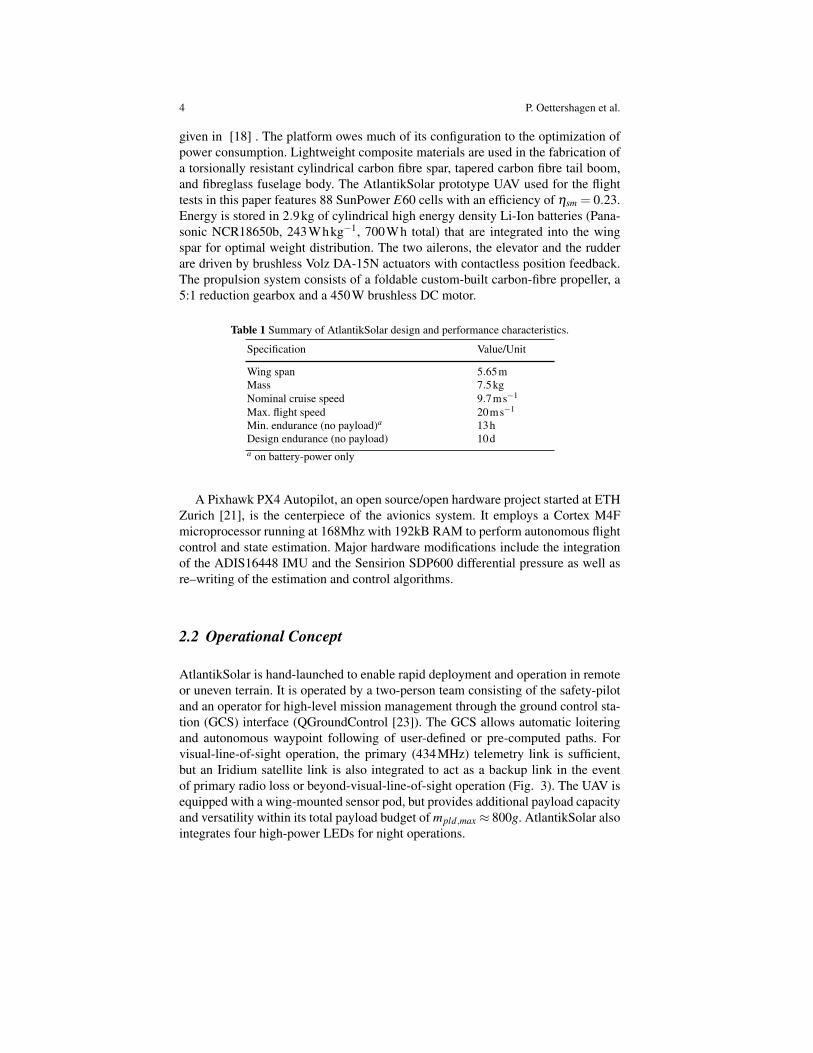
given in [18] . The platform owes much of its configuration to the optimization ofpower consumption. Lightweight composite materials are used in the fabrication ofa torsionally resistant cylindrical carbon fibre spar, tapered carbon fibre tail boom,and fibreglass fuselage body. The AtlantikSolar prototype UAV used for the flighttests in this paper features 88 SunPower E60 cells with an efficiency of ηsm = 0.23.Energy is stored in 2.9kg of cylindrical high energy density Li-Ion batteries (Pana-sonic NCR18650b, 243Whkg−1, 700Wh total) that are integrated into the wingspar for optimal weight distribution. The two ailerons, the elevator and the rudderare driven by brushless Volz DA-15N actuators with contactless position feedback.The propulsion system consists of a foldable custom-built carbon-fibre propeller, a5:1 reduction gearbox and a 450W brushless DC motor.
Table 1 Summary of AtlantikSolar design and performance characteristics.
Specification Value/Unit
Wing span 5.65mMass 7.5kgNominal cruise speed 9.7ms−1
Max. flight speed 20ms−1
Min. endurance (no payload)a 13hDesign endurance (no payload) 10da on battery-power only
A Pixhawk PX4 Autopilot, an open source/open hardware project started at ETHZurich [21], is the centerpiece of the avionics system. It employs a Cortex M4Fmicroprocessor running at 168Mhz with 192kB RAM to perform autonomous flightcontrol and state estimation. Major hardware modifications include the integrationof the ADIS16448 IMU and the Sensirion SDP600 differential pressure as well asre–writing of the estimation and control algorithms.
2.2 Operational Concept
AtlantikSolar is hand-launched to enable rapid deployment and operation in remoteor uneven terrain. It is operated by a two-person team consisting of the safety-pilotand an operator for high-level mission management through the ground control sta-tion (GCS) interface (QGroundControl [23]). The GCS allows automatic loiteringand autonomous waypoint following of user-defined or pre-computed paths. Forvisual-line-of-sight operation, the primary (434MHz) telemetry link is sufficient,but an Iridium satellite link is also integrated to act as a backup link in the eventof primary radio loss or beyond-visual-line-of-sight operation (Fig. 3). The UAV isequipped with a wing-mounted sensor pod, but provides additional payload capacityand versatility within its total payload budget of mpld,max ≈ 800g. AtlantikSolar alsointegrates four high-power LEDs for night operations.

Long-Endurance Sensing and Mapping using a Hand-Launchable Solar-Powered UAV 5
BackupSCommQSLink
RadioSControl
HandSLaunch
2Q4SGHzS5visualSrange1
5Spektrum1
5IridiumSSatelliteSLink1
PrimarySCommQSLink53DRSRadio1
434SMHzS5<5SkmSrange1
1620SMHzS5globalScoverage1
USBInternet
GroundSControlSStation 5QGroundControl1
Fig. 3 Communications and ground control.
2.3 Enabling Technologies for Autonomous Navigation
2.3.1 Robust Long-Term State Estimation
To provide reliable and drift-free long-term autonomous operation, a light-weightEKF-based state estimator, as presented in [11], is implemented on the autopilot.It fuses data from a 10-DoF Inertial Measurement Unit (IMU) with GPS-Position,GPS-velocity and airspeed measurements in order to successively estimate position,velocity, orientation (attitude and heading), QFF as well as accelerometer and gyrobiases. Robustness against temporal GPS losses is enhanced through the inclusion ofairspeed measurements from a differential barometer. To increase flight safety, thealgorithm estimates the local three-dimensional wind vector and employs an internalaircraft aerodynamics model to estimate the current sideslip angle and Angle ofAttack (AoA), which can in turn be used by the flight controller to apply implicitflight regime limits, as in the case of the authors’ previous work [17].
2.3.2 Flight Control
AtlantikSolar’s flight control system features automatic tracking of waypoints alongpre-defined paths, allows extended loitering around areas of interest and implementssafety-mechanisms such as automatic Return-To-Launch (RTL) in case of prolongedremote control or telemetry signal losses. The baseline control is a set of cascadedPID-controllers for inner-loop attitude control [2]. Output limiters are applied to re-spect the aircraft flight envelope, dynamic pressure scaling of the control outputsis used to adapt to the changing moment generation as a function of airspeed and a

6 P. Oettershagen et al.
coordinated-turn controller allows precise turning. Altitude control is based on a To-tal Energy Control System that also allows potential energy gains in thermal updraftwhile it implements safety mechanisms such as automatic spoiler deployment dur-ing violation of maximum altitude limits. Waypoint-following is performed usingan extended version of the L1-nonlinear guidance logic [19]. The detailed imple-mentation and verification of our autopilot is described in [18].
2.3.3 Inspection Path–Planner
An inspection path–planning algorithm is integrated into the system in order to en-able automated inspection and mapping of large scale 3D environments. The algo-rithm is inherently tailored for structural inspection and computes full coverage andcollision–free paths subject to a model of the nonholonomic constraints of the ve-hicle. The overall approach is illustrated in Fig. 4, while a detailed description isavailable in the authors’ previous work [1]. It essentially corresponds to an explicitalgorithm that computes an inspection path based on a mesh–model representationof the desired world. It iteratively tries to compute viewpoint configurations thatprovide full coverage while at the same time employing the Lin-Kernighan heuris-tic [12] in the search for the best route that visits all of them subject to the motionconstraints of the vehicle. Via a viewpoint resampling technique that employs ran-domized sampling, the designed algorithm allows for an iterative improvement ofthe path cost while always retaining complete coverage. Fast collision–free naviga-tion is achieved via a combination of a Boundary Value Solver for the consideredvehicle model with the RRT? [9] motion planner.
Surface Mesh Model Load Aerial Robot Dynamic Model & Constraints
Initial Viewpoints SamplingBoundary Value Solver
and RRT*-based TSP Cost Matrix
Solve TSP
Obtain first solution
Viewpoint ResamplingSolve TSP
Obtain bestsolution
LKH Heuristic
Boundary Value Solver
and RRT*-based TSP Cost Matrix
Available
Time?
Fig. 4 Summary of the employed 3D inspection path–planning algorithm.

Long-Endurance Sensing and Mapping using a Hand-Launchable Solar-Powered UAV 7
3 Sensor Pod
The sensor pod (see Fig. 5) features a grayscale (Aptina MT9V034) camera with ahigh dynamic range and a long-wavelength infrared (LWIR) camera (FLIR Tau 2)for thermal imaging, both mounted with an oblique field of view (FOV), as well asa nadir facing RGB camera (uEye XS 2). An IMU (Analaog Devices ADIS16448)is also included, measuring linear accelerations, angular velocities, and the mag-netic field in all three axes. All sensors are integrated with a Skybotix VI-sensor[27], allowing tight hardware synchronization and timestamping of the acquired data[15]. Furthermore, a state of the art embedded computer (Kontron COMe-mBT10),with an Intel Atom CPU (4 cores, 1.91GHz) and a thermal design power (TDP)of 10W, is interfaced with the VI-sensor and the PX4 autopilot board of the UAV.The on–board Atom computer further communicates with the PX4 in order to re-ceive all global pose estimates and raw sensor data and transmit waypoints. Theacquired data is processed on–board and communication with the ground controlstation is achieved over Wi–Fi. As shown in Fig. 5, all components are mounted ona lightweight aluminum construction ensuring a rigid connection between the cam-eras and the IMU, thus guaranteeing high quality extrinsic calibration of the sensors,a key element for accurate visual-inertial localization.
Fig. 5 The sensor pod as it is currently used on the AtlantikSolar without fairing for better visibilityof the components.
The on-board computer runs a standard Ubuntu Linux operating system, allow-ing quick adaptation to different kinds of missions. Furthermore, it enables rapidtesting of new algorithms, e.g. for localization and mapping. It has been utilizedto evaluate monocular localization [10] while the original stereo version of theVI–sensor is actively used for localization of rotary–wing UAVs in possibly GPS–denied environments [14]. Within the framework of the research projects ICARUSand SHERPA [8, 26], the described sensor pod is used for area mapping, victimdetection, and situational awareness tasks. The data of the visible light cameras iscombined with the pose estimates and fed to post–processing software [20] to de-rive accurate 3D reconstructions of the environment. Active research is ongoing foraerial victim detection at altitudes on the order of 100m.

8 P. Oettershagen et al.
4 Flight Experiments
AtlantikSolar is a key component of several research projects and has actively partic-ipated in multiple large–scale demonstration events. Within this paper, indicative re-sults from the ICARUS project [8] public field–trials event at Marche–en–Famenne,Belgium and a long–endurance mapping mission in Rothenthurm, Switzerland arepresented along with flight endurance related tests and evaluations. A dataset is alsoreleased and documented to accompany this paper. It contains the vehicle state es-timates, IMU and GPS raw data, the camera frames from all the on–board modulesas well as post–processed reconstructions of the environment for the field–trials de-scribed in Section 4.2. This rich dataset is publicly available at [5].
4.1 Search–and–Rescue Application Demonstration
During the ICARUS project field–trials in Marche–en–Famenne [8], the AtlantikSo-lar UAV was commanded to autonomously execute inspection paths that ensured thecomplete coverage of a predefined area in order to assist the area monitoring, map-ping, victim detection and situational awareness necessities of Search–and–Rescuerapid response teams. Employing the path–planner overviewed in Section 2.3.3 andbased on the long–endurance capabilities of the UAV, the area was scanned repeat-edly over multiple hours. An example inspection path is depicted in Fig. 6 and cor-responds to an optimized solution for the case of the oblique–view mounted ther-mal camera, FOV (56◦,60◦) for the horizontal and vertical axes, respectively. Themounting orientations of the grayscale and the thermal camera are identical, but theFOV of the grayscale camera is larger in all directions (70◦,100◦), thus the plannedpath provides full coverage for both vision sensors.
During the execution of these inspection paths, the two camera–system and thepose estimates of the aircraft were uniformly timestamped and recorded in a ROSbag. Subsequently, post–processing of the grayscale images was conducted in orderto derive a dense point–cloud of the area using the Pix4D software [20]. An imageof the derived result is shown in Fig. 7, while additional results of autonomouslyexecuted inspection paths may be found in our previous work [1].
4.2 Area Coverage Application Demonstration
In this specific field experiment, the AtlantikSolar UAV’s capabilities for long–termarea coverage, inspection and mapping were evaluated. Within 6 hours of flight,the system performed multiple lawn–mowing and other paths like those presentedin Fig. 8. With a camera frame recording rate set at Fc = 1Hz, synchronizationwith the vehicle pose estimates and properly designed waypoint distances to ensurecoverage and sufficient overlap for all cameras, a solid reconstruction result was

Long-Endurance Sensing and Mapping using a Hand-Launchable Solar-Powered UAV 9
Fig. 6 Inspection path full area coverage using the oblique–view mounted thermal vision andgrayscale cameras of the AtlantikSolar sensor pod. The colored mosaic was derived using an addi-tional very large field of view nadir–facing camera (HDR-AS100VW).
Fig. 7 Reconstructed dense point cloud based on the combination of the oblique–view grayscalecamera images with the vehicle position estimates. The reconstruction was achieved using thePix4D mapping software.
achieved. Within this flight, all three cameras were employed and Fig. 9 depicts thereconstructed point cloud using a combination of the geo–tagged nadir–facing RGBcamera of the sensor pod with the, likewise, geo–tagged oblique–view grayscale im-ages, while Fig. 10 shows false–colored thermal images that our team is currentlyaiming to employ for victim detection, extending previous work [22] at ASL. Anopen dataset containing 1 hour of raw data and post–processed results is released toaccompany this paper and may be found at [5].

10 P. Oettershagen et al.
Fig. 8 The lawn–mowing path executed by the AtlantikSolar UAV overlayed on the reconstructedmosaic of the environment, incorporated in Google maps.
Fig. 9 The reconstructed point–cloud of the Rothenthurm area based on the combination of theRGB and grayscale camera data as well as the UAV pose estimates collected during the lawn–mowing path and subsequently processed using the Pix4D software.
Fig. 10 False–colored thermal camera images recorded using the on–board sensor pod of the At-lantikSolar UAV.

Long-Endurance Sensing and Mapping using a Hand-Launchable Solar-Powered UAV 11
4.3 Full-Payload Flight Endurance and Range
After having shown a flight endurance of more than 12 hours without payload inSummer 2014 [18], the area coverage demonstration in Rothenthurm on Novem-ber 21st was used to determine AtlantikSolar’s maximum flight endurance with thefull sensor pod payload of mpayload = 610g during winter conditions. Fig. 11 showsthe corresponding power income, output, and battery state. The average power con-sumption during the flight is Paircra f t = 69.7W plus Ppayload = 15W for the sensorpod. After take-off at 10:25am local time at 94% battery state-of-charge (SoC), theheavily attitude-dependent solar power income increases but reaches only a maxi-mum of 80W at noon due to the limited insolation in winter. Nevertheless, as in-dicated by the SoC, the system power is mostly drawn from the solar panels formore than 3 hours of the flight. Power income decreases towards the afternoon:The solar panel maximum power point trackers (MPPTs) are still operating, but thepanel voltage has decreased significantly and the MPPTs deliver currents below themeasurement threshold. However, the remaining SoC during landing shortly beforesunset (4:28pm local time) is still 52%. Extrapolating using the total power con-sumption of Ptot = Paircra f t +Ppayload = 69.7W +15W = 84.7W yields an additional4.32 hours of remaining flight endurance assuming zero-radiation conditions andthus a total flight endurance of ca. 10h with full payload for the installed 700Whbattery during these winter conditions.
0
100
200
300
Po
we
r O
utp
ut
Paircraft
Paircraft,avrg
[W]
0
25
50
75
100
Po
we
r In
co
me
10
15
20P
Solar [W]
USolar
[V]
0 1 2 5 60
0.2
0.4
0.6
0.8
1
Flight time since launch [hrs]
Ba
tte
ry s
tate
Battery State−of−Charge [%]
...
[W]
Fig. 11 Power income, output and battery state-of-charge for the Rothenthurm mapping flight.AtlantikSolar covered 243km ground-distance, was airborne for 6 hours 3 minutes and landedshortly before sunset (4:28pm local time) with 52% battery capacity remaining.
The recorded power consumption of Ptot = 84.7W was taken as the input for theflight endurance simulation in Fig. 12. Assuming launch of the airplane exactly atsunrise, full-daylight flight endurance is provided throughout the full year including

12 P. Oettershagen et al.
winter under most atmospheric conditions. More specifically, full-daylight flight ca-pability is only lost when CLR = PSolar/PSolar,ClearSky is smaller than ca. 0.3 in sum-mer and ca. 0.15 in winter, which corresponds to severe cloud coverage or fog thatmay hinder flight operations independently of energy considerations. The maximumendurance of AtlantikSolar with the full payload is 22.4 hours on June 21st, whichmeans that perpetual flight is not possible. Note that in all atmospheric conditions,a minimum endurance of 8 hours can be guaranteed through battery-powered flightalone. At the chosen airspeed of vair = 11.02m/s, AtlantikSolar can thus cover aground distance of 317km (min. endurance) to 888km (max. endurance). Note thatthis airspeed provides the maximum range (optimal glide ratio), but is not the power-optimal airspeed (lowest rate of sink). Flying strictly at the power-optimal airspeedfound in [18] would e.g.increase the endurance to 23.9 hours on June 21st, with bat-tery energy depleting shortly before sunrise. This means that perpetual flight withthe full sensor payload can theoretically be achieved through minor aircraft opti-mizations, e.g. through a slight increase of the available battery capacity. However,note increasing endurance through power-optimal airspeed selection in the non-perpetual flight endurance case comes at a cost of range, and should be consideredper application.
J F M A M J J A S O N D
8
10
12
14
16
18
20
22
24
CLR=0 (min. endurance)
CLR=0.2
CLR=0.4
CLR=0.6
CLR=0.8
CLR=1 (max. endurance)
Month of year [−]
Flig
ht
En
du
ran
ce [
h]
vs.
atm
osp
he
re c
lea
rne
ss (
CL
R)
June 21st
Dec. 21st
Flight endurance [h] (max/min)
Flight endurance [h]
Length of daylight [h]
Fig. 12 AtlantikSolar’s flight endurance with 610g/15W payload versus atmospheric clearness(CLR) for φ = 47oN (Rothenthurm, CH) when assuming launch at sunrise with SoC=100%. Fulldaylight flight is possible throughout the whole year (green area), and only severe cloud coveragecan reduce endurance below the daylight duration (red area). In all cases 8 hours of minimumendurance are achieved.

Long-Endurance Sensing and Mapping using a Hand-Launchable Solar-Powered UAV 13
5 Conclusions
In this work, we have demonstrated a significant leap in long–endurance, low–altitude aerial sensing and mapping. Utilizing optimized solar aircraft design method-ologies, low power consumption electronics, a robust autonomous navigation frame-work, and a versatile, modular, and self-contained sensor payload, the AtlantikSolarsystem, as a whole, provides a baseline to address quickly approaching societalneeds related to long-term aerial robotic operations. Extensive field–trial experi-ence indicates that solar power is a promising solution towards providing long en-durance to small–sized, low–altitude UAVs, and integrated sensor suites, when usedin tandem with autonomous navigation and planning methods, can provide wealthof valuable information to end users in an efficient manner. Still, there is great roomfor improvement, especially in the directions of autonomous navigation close to ter-rain, where a combination of advanced perception and planning algorithms have tobe employed. Also in terms of superior robustness, as required for multi–hour oreven multi–day flight.
Acknowledgements This work was supported by the European Commission projects ICARUS(#285417) and SHERPA (#600958) under the 7th Framework Programme. Further information athttp://www.atlantiksolar.ethz.ch/
References
[1] Bircher A, Alexis K, Burri M, Oettershagen P, Omari S, Mantel T, Siegwart R(2015) Structural inspection path planning via iterative viewpoint resamplingwith application to aerial robotics. In: Robotics and Automation (ICRA), 2014IEEE International Conference on, (accepted)
[2] Brian L Stevens and Frank L Lewis (1992) Aircraft Control and Simulation.Wiley Interscience
[3] Cyberhawk - Remote aerial inspection and land surveying specialists (2015)http://www.thecyberhawk.com/
[4] Falcon UAV (2015) http://www.falconunmanned.com/[5] FSR 2015 - Solar-powered UAV Sensing and Mapping Dataset (2015)
http://projects.asl.ethz.ch/datasets/doku.php?id=fsr2015[6] Girard A, Howell A, Hedrick J (2004) Border patrol and surveillance missions
using multiple unmanned air vehicles. In: Decision and Control, 2004. CDC.43rd IEEE Conference on
[7] Hunt ER, Hively WD, Fujikawa SJ, Linden DS, Daughtry CST, McCarty GW(2010) Acquisition of nir-green-blue digital photographs from unmanned air-craft for crop monitoring. Remote Sensing 2(1):290–305
[8] ICARUS: Unmanned Search and Rescue (2015) http://www.fp7-icarus.eu/[9] Karaman S, Frazzoli E (2010) Incremental sampling-based algorithms for op-
timal motion planning. CoRR abs/1005.0416

14 P. Oettershagen et al.
[10] Leutenegger S (2014) Unmanned solar airplanes: Design and algorithms forefficient and robust autonomous operation. PhD thesis, ETH Zurich
[11] Leutenegger S, Melzer A, Alexis K, Siegwart R (2014) Robust state estima-tion for small unmanned airplanes. In: IEEE Multi-conference on Systems andControl
[12] Lin S, Kernighan BW (1973) An effective heuristic algorithm for the traveling-salesman problem. Operations research 21(2):498–516
[13] Metni N, Hamel T (2007) A UAV for bridge inspection: Visual servoing con-trol law with orientation limits. Automation in Construction 17(1):3–10
[14] Nikolic J, Burri M, Rehder J, Leutenegger S, Huerzeler C, Siegwart R (2013) AUAV System for Inspection of Industrial Facilities. In: IEEE Aerospace Con-ference
[15] Nikolic J, Rehder J, Burri M, Gohl P, Leutenegger S, Furgale PT, SiegwartRY (2014) A Synchronized Visual-Inertial Sensor System with FPGA Pre-Processing for Accurate Real-Time SLAM. In: IEEE International Conferenceon Robotics and Automation (ICRA)
[16] Noth A (2008) Design of solar powered airplanes for continuous flight. PhDthesis, ETH Zurich
[17] Oettershagen P, Melzer A, Leutenegger S, Alexis K, Siegwart R (2014) Ex-plicit Model Predictive Control and L1-Navigation Strategies for Fixed-WingUAV Path Tracking. In: 22nd Mediterranean Conference on Control & Au-tomation (MED)
[18] Oettershagen P, Melzer A, Mantel T, Rudin K, Lotz R, Siebenmann D,Leutenegger S, Alexis K, Siegwart R (2015) A Solar-Powered Hand-Launchable UAV for Low-Altitude Multi-Day Continuous Flight. In: IEEEInternational Conference on Robotics and Automation (ICRA)
[19] Park S, Deyst J, How JP (2004) A new nonlinear guidance logic for trajec-tory tracking. In: AIAA Guidance, Navigation, and Control Conference andExhibit, pp 16–19
[20] Pix4D (2015) http://pix4d.com/[21] Pixhawk Autopilot (2015) http://pixhawk.org/[22] Portmann J, Lynen S, Chli M, Siegwart R (2014) People detection and track-
ing from aerial thermal views. In: Robotics and Automation (ICRA), IEEEInternational Conference on, pp 1794–1800
[23] QGroundControl (2015) http://www.qgroundcontrol.org/[24] QinetiQ (2010) QinetiQ files for three world records for its
Zephyr Solar powered UAV. QinetiQ Press Release, retrieved fromhttp://www.qinetiq.com/media/news/releases/Pages/three-world-records.aspx
[25] Rudol P, Doherty P (2008) Human body detection and geolocalization for uavsearch and rescue missions using color and thermal imagery. In: AerospaceConference, 2008 IEEE, pp 1–8
[26] SHERPA Project (2015) http://www.sherpa-project.eu/[27] Skybotix AG (2015) http://www.skybotix.com/