long-term leakage failure of filament-wound … · (3). outstanding fatigue resistance, (4)....
TRANSCRIPT

LONG-TERM LEAKAGE FAILURE OF FILAMENT-WOUND FIBERGLASS COMPOSITE LAMINATE TUBING UNDER
COMBINED INTERNAL PRESSURE AND AXIAL LOADING
BY
S. S. Wang* and S. Srinivasan**
Composites Engineering and Applications Center, and Department of Mechanical Engineering
University of Houston 4800 Calhoun Road
Houston, TX 77204-0900
December, 1996
*Professor and Director, CEAC and Mechanical Engineering Department **Research Associate, CEAC; Formerly, Graduate Research Assistant,
Department of Mechanical Engineering


(Report #1 of the Final Report Series to American Petroleum Institute and Amoco Corporation for the Project on Long-Term Multiaxial Strength of Fiberglass Tubing)
LONG-TERM LEAKAGE FAILURE OF FILAMENT-WOUND FIBERGLASS COMPOSITE LAMINATE TUBING UNDER COMBINED
INTERNAL PRESSURE AND AXIAL LOADING
S. S. Wang* and S. Srinivasan**
Composites Engineering and Applications Center, and Department of Mechanical Engineering
University of Houston 4800 Calhoun Road
Houston, TX 77204-0900
December. 1996
* Professor and Director, CEAC and Mechanical Engineering Department **Research Associate, CEAC; Formerly, Graduate Research Assistant, Department of Mechanical Engineering


Forward
This report is the first part in the final report series for the project on long-term multiaxial strength of fiberglass tubing, conducted during the period of 1994-96 by researchers of the Composites Engineering and Applications Center (CEAC) for Petroleum Exploration and Production at the University of Houston, Houston, TX. The research was funded mainly by a contract from the American Petroleum Institute (API), Washington D. C. Owing to the broad scope of work and the depth of the investigation, supplementary support was also provided by a grant from the Amoco Corporation, Chicago, EL and by CEAC internal funds.
The overall objectives of the research program, as requested by API, were to: (1). Examine the validity of the assumptions and hypotheses of the proposed APZ rating methodology for long-term strength of fiberglass composite tubing under multiaxial loading; (2). Provide rigorous understanding of progressive !eakage failure mechanisms and mechanics of FRP tubing subjected to combined internal pressurc and axial loading, and (3). Identify the limitations of the proposed API rating rriethodology.
The current study has been directed to fscus on the following critical issues of the leakage failure in fiberglass composite tubing used in oil and gas exploration and production operations: ( I ) . Progressive leakage failure modes; (2). Long-term and short-term leakage failure envelopes; (3). Safety (or service) factors in composite tubing design, and (4). Load sequence effects. Both composite tube bodies and threaded fiber-composite joints were studied. Two types of composite tubing were considered; one for downhole applications and the other f ~ r typical line pipe applications. The effect of different multiaxial loading modes, including short-term loading, long-term creep and cyclic fatigue, on the composite tubing leakage was investigated.
This first report addresses the aforementioned critical issues of leakage failure in a fiberglass composite tube body . In the second report, the complicated leakage failure of threaded fiber-composite tubular joints is investigated. The third report covers the important problem of long-term cyclic fatigue strength prediction methodology for fiber composite under multiaxial loading. In all these reports, the analytical and experimental methods developed for the studies are described in detail to ensure a clear understanding of the advanced level of the approach used i n the investigation.


ABSTRACT
Filarnent-wound, fiber-reinforced polymer-matrix composite laminate tubing has been used for a wide range of engineering applications, owing to their high specific stiffness, strength and superior corrosion resistance. Functional failure in the form of leakage in the composite tubes under multiaxial loading has been an important but not well understood issue. In this report, a systematic study, based on rigorous analyses and well- controlled experiments, has been conducted to investigate the failure mechanisms and mechanics of filament-wound composite tubes under combined internal pressure and axial loading. Both short-term and long-term leakage failure of the composite tubes are studied.
With the aid of experiments on hoop-wound E-glass/epoxy composite tubes, matrix-dominated deformations and ply failure modes are determined first. Nonlinear constitutive equations and the physical mechanism-based failure criteria have been established for the observed deformation and failure.
In the analytical part of the leakage study of composite laminate tubing, a ply-by- ply, progressive failure analysis is required. Both three-dimensional anisotropic laminate elasticity theory and a two-dimensional lamination approach are used to analyze thick- and thin-wall composite cylindrical tubing, respectively. The advanced analyses developed here include nonlinear constitutive equations for individual plies, a homogenization theory of distributed matrix cracks in damaged plies, and the physical mechanism-based criteria for different failure modes of individual plies in the composite laminate tubing. Computational methods developed in the study involve an incremental-iterative algorithm for modeling the progressive damage in the composite tubes under combined interilal pressure and axial loading. In the experimental phase of the study, short-term and long- term leakage-failure experiments have been conducted on [ (k55") I2 and [(+66°)2/(00)./(k660)./(00~]s E-glass/epoxy composite laminate tubes under biaxial loading. Leakage-failure modes and failure envelopes have been obtained for each case and compared with the analytical predictions. The important effects of time, temperature and multiaxial loading on long-term leakage failure of the composite laminate tubes have been determined. The influences of material nonlinearity, composite lamination variables, and stress biaxiality ratio on the leakage-failure behavior are addressed in detail. The use of a properly formulated kinetic failure theory of polymer composites for accelerated leakage prediction of the composite tubing is also discussed.


v
TABLE OF CONTENTS
FORWARD - Ill
ABSTRACT iv
TABLE OF CONTENTS v
1 . INTRODUCTION 1
2 . LITERATURE REVIEW 3
2.1 Deformation and Failure of Unidirectional Fiber Composites 2.2 Short-Term Leakage in Fiber-Composite Laminate Tubes 2.3 Long-Term Leakage Failure
3 . OBJECTIVES AND OUTLINE OF METHODS OF APPROACH 9
4 . LEAKAGE-FAILURE EXPERIMENTS ON FILAMENT-WOUND GLASS-FIBER/EPOXY COhlYOSITE LAMINATE TUBING 10
4.1 Filament-Wound Composite and Tubular Composite Laminate Specimens 10 4.2 Analysis and Design of the Tubular Composite Specimens 10 4.3 Experimental Facility Development 11 4.4 Experimental Procedure 12
5 . METHODS OF ANALYSIS FOR FILAMENT-WOUND COMPOSITE LAMINATE TUBING 13
5.1 Constitutive Equations for Hoop-Wound (Unidirectional) Composites 13 5.2 Methods of Analysis of Cylindrical Composite Laminate Tubing 14
5.2.1 Thick-wall filament-wound composite laminate tubing 14 5.2.2 Thin-wall filament-wound cylindrical composite laminate shells 18
5.3 Remarks 20
6 . DAMAGE MODELING AND ANALYSIS BY HOMOGENIZATION THEORY 22
6.1 Homogenization Formulation for Modeling Filament-Wound Composites with Transverse Cracks 22
6.2 Effective Sliffness Determination of Filament-Wound Composites with Transverse Cracks 24
6.3 Progressive Property Degradation of Filament-Wound Composite Laminates under Increasing Loading 25


7 . PHYSICAL MECHANISM-BASED FAILURE CRITERIA FOR HOOP-WOUND COMPOSITES 27
7.1 Fiber-Dominated Ply Failure 7.2 Matrix-Dominated Ply Failure
8 . LONG-TERM LEAKAGE FAILURE OF FILAMENT-WOUND COMPOSITE LAMINATE TUBING UNDER COMBINED INTERNAL PRESSURE AND AXIAL LOADING 3 1
8.1 Time-Temperature-Dependent Constitutive Equations for Hoop-Wound Composite 3 1
8.2 Time-Temperature-Dependent Failure Criteria for Hoop-Wound Composites 32 8.2.1 Kinetic theory for matrix-dominated cracking in hoop-wound
fiber composites 32 8.2.2 Long-term leakage-failure criteria for filament-wound composite
laminate tubes 33 8.3 Viscoelastic Analysis for Long-Term Leakage Failure of Fiber-Composite Laminate
Tubes 34 8.3.1 Nonlinear viscoelastic analysis of fiber-composite laminate tubes 34 8.3.2 Nonlinear viscoelastic analysis of filament-wound composite laminate
tubes with progressive damage 34
9 . DEVELOPMENT OF COMPUTATIONS ALGORITHMS FOR LEAKAGE FAILURE OF FILAMENT-WOUND COMPOSITE LAMINATE TUBING 3 6
9.1 Incremental-Iterative Algorithm for Progressive Damage and Degradation 36 9.2 Incremental Stress and Deformation during Progressive Damage 3 6 9.3 Algorithm for Leakage-Failure Determination for Filament-Wound Composite
Laminate Tubes 37 9.4 Long-Term Leakage-Failure Prediction Algorithmat Different Temperatures and
Loads 38
10. RESULTS AND DISCUSSION 40
10.1 Short-Term Leakage Failure Experiments on Filament-Wound Glass-FiberEpoxy Composite Tubes 40
10.1.1 Multiaxial deformation and leakage-failure envelope 40 10.1.2 Leakage-failure modes 4 1
10.2 Short-Term Leakage-Failure Analysis and Prediction 4 1 10.2.1 Anisotropic laminate elasticity vs. CLT solutions for stresses in
thick-walled composite laminate tubes 4 1 10.2.2 Deformations in thick-wall composite laminate tubes 4 1 10.2.3 Effect of material nonlinearity and loading biaxiality ratio 42 10.2.4 Leakage failure prediction 42
10.3 Long-Term Leakage Failure in Filament-Wound Glass~Epoxy Composite Tubes 43 10.3.1 Experimental results 43 10.3.2 Long-term leakage-failure analysis (Isothermal) 43


vii
11. CONCLUSIONS
12. REFERENCES
13. FIGURES
14. TABLES
APPENDIX A. DEFORMATION AND FAILURE OF HOOP- WOUND GLASS-FIBERIEPOXY COMPOSITE SUBJECTED TO COMBINED TORSION AND AXIAL LOADING
A. 1 Materials and Specimen Preparation A.2 Experimental Facilities A.3 Data Acquisition A.4 Experimental Method and Procedure A.5 Mechanical Behavior of Hoop-Wound E-glass/epoxy Composite A.6 Failure Modes A.7 Matrix-L)ominatcd Multiaxial Failure Criteria
APPENDIX B. TIME-TEMPERATURE-DEPENDENT MECHANICAL PROPERTIES OF HOOP-WOUND GLASS-FIBER/EPOXY COMPOSITE SUBJECTED TO COMBINED TORSION AND AXIAL LOADING
B. 1 Materials and Specimen Preparation. B.2 Experiments B.3 Resuits and Discussion
APPENDIX C. EFFECTIVE PLY STIFFNESS DEGRADATION OF COMPOSITE LAMINATES DUE TO TRANSVERSE CRACKS
FIGURES IN APPENDICES
TABLES IN APPENDICES


1. INTRODUCTION
Fiber-reinforced composites have been widely and successfully employed in many primary load-bearing components in aerospace, automotive and marine structures. These materials have also been used in oil and gas exploration, production and transmission operations. However, the use of fiber composites in the petroleum industry has been mostly restricted to glass fiber-reinforced composite tubing and other secondary components. The viability of combining glass, Kevlar, and graphite fibers in various forms of hybrid composites is under development for advanced and more severe applications [I], including rigid composite risers, flexible risers, coiled tubing, tethers, drill pipe, subsea flow lines, and other high-pressure vessels and tanks. Most of these current applications and developments in the petroleum engineering exploration and production (E & P) are based on products made from filament winding processes and the composite components are generally subjected to combined internal pressure and externai axial loading.
Besides their excellent specific stiffness and strength, other pertinent advantages of utilizing polymer-matrix fiber composites over metals in the petroleum E & P operations may include the following: ( I ) light weight, (2). superior corrosion resistance, (3). outstanding fatigue resistance, (4). unlimited potential of material and structural tailoring for specific applications, (5). ease in installation and fabrication, and (6). low maintenance and life-cycle costs.
Among various concerns in the use of the filament-wound fiber-composite tubing is leakage failure under different combinations of internal pressure and axial loading, especially the long-term multiaxial strength. It is well known that the leakage failure of a filament-wound composite can precede burst failure, owing to the anisotropic and heterogeneous nature of the composite. The leakage failure is governed by different microscopic damage mechanisms in a load-bearing structural composite laminate shell. To realize the full potential of the filament-wound composite tubing, a thorough understanding of the leakage-failure mechanisms and associated mechanics is necessary. Reliable long- term performance of a fiber-composite laminate tubing can be ensured only when predictive methodologies and accelerated test methods are properly developed.
Filament-wound composite tubes are essentially layered fiber-composite cylindrical shells with unidirectional fiber-composite plies, with each ply having a different fiber orientation. The inherently anisotropic mechanical properties of each ply induce complex stress states in the plies when the tubes are subjected to multiaxial external loads such as the combined internal pressure and axial loading. Leakage failure of fiber-composite tubing is consequently rather intricate, containing a complex process of initiation and growth of cracks through the wall of the composite shell. The onset of leakage is generally ascribed to formation of interconnected cracks through the constituent plies of the tubes, providing a through-the-thickness path for fluid seepage. Microscopically, the cracks are generally formed in the matrix and/or along the fiberlmatrix interface. The orientation and density of the cracks in individual plies at leakage depend on the composite lamination parameters and the applied multiaxial loading. Hence a ply-by-ply progressive failure evaluation of the

formation of through-the-thickness transverse cracks is essential to determine the leakage- failure process.
The mechanical strength dong the fiber direction of a composite lamina is governed by the strength, stiffness, and volume fraction of the reinforcing fibers. Transverse and shear strengths of a composite ply are dictated mostly by the matrix properties. Most studies on failure of fiber-composite laminates in the past have been concentrated on the loss of structural load-bearing capacity caused by fiber failure in the plies. Clearly in the current leakage-failure study, transverse ply cracking (i.e., matrix-dominated ply failure) is of critical interest and the multiaxial strength and failure modes of an individual composite ply are the most fundamental issues to be studied first. In addition, the matrix phase in a fiber composite may exhibit an appreciable amount of viscoelasticity at an elevated temperature even for a short duration of loading when an accelerated test method is introduced for determining the long-term leakage failure. A proper long-term leakage study on a filament-wound fiber-composite tubing under multiaxial loading requires both the matrix- and fiber-dominated ply deformations and failure strengths be thoroughly investigated first.
Since the composite tubing leakage involves progressive damage of constituent plies in the form of ply cracking, at each stage of damage evolution, the composite plies with damage affect deformations and consequently failure of adjacent plies. A proper leakage-mechanics analysis of the filament-wound composite tubing must be formulated in terms of ply failure in a multiaxial stress/strain state. An incremental procedure, involving the recently developed continuum damage mechanics concept for an anisotropic, heterogeneous composite, should be introduced during subsequent laminate deformations. Advanced computational mechanics methods are needed to incorporate all the complicated failure mechanisms, damage homogenization and nonlinear anisotropic constitutive properties of the composite.
To this end, nonlinear deformations, failure modes and associated failure criteria of hoop-wound unidirectional fiber composites are studied first. Details of the study are reported in Appendix A and B. A critical review of the literature on both unidirectional composite failure and leakage in multi-directional composite laminate tubes has been made in Sec. 2. The emphasis is placed on the matrix-dominated damage and failure attributes. In Sec. 3, the objectives of the study and the proposed approaches are outlined. The experimental program to study the leakage failure in glass-fiber reinforced epoxy-composite laminate tubes subjected to different biaxial loading (i.e., internal pressure and axial loading) is given in Sec. 4. A theoretical model for analyzing thick-wall composite laminate tubing subjected to multiaxial loading, based on three-dimensional anisotropic laminate elasticity theory, is developed in Sec. 5. The method of analysis of thin-wall composite laminate tubes is also presented for completeness. A recently developed homogenization scheme is introduced in Sec. 6 to account for the effects of local ply damage on the effective property degradation of the filament-wound fiber-composite laminate tubing. Physical mechanism-based criteria for fiber and matrix-dominated failure of hoop-wound composites are discussed in Sec. 7. A kinetic failure theory, based on time-temperature dependent polymer failure, for studying the long-term composite tubing leakage failure is introduced in Sec. 8. A computational scheme involving an incremental- iterative algorithm, developed for analyzing the leakage of a composite laminate tube. is presented in Sec. 9. Analytical predictions are presented in Sec. 10 for leakage failure of glass-fiber reinforced epoxy composite tubes with different laminate layups (for the cases of downhole and line pipe tubing) subjected to combined internal pressure and axial loading. The analytical predictions are discussed and compared with experimental data. Important conclusions drawn from this study are given in Sec. 1 1.
I


2. LITERATURE REVIEW
Leakage in a filament-wound composite laminate tubing encompasses several fundamental characteristics of deformation and failure, involving basic mechanical properties of a fiber-reinforced composite material under multiaxial loading. During deformation prior to failure individual constituent plies of the composite tubing may exhibit nonlinear constitutive behavior. The progressive failure process leading to the composite tubing leakage requires proper failure criteria for matrix-dominated cracking in a hoop- wound (unidirectional) fiber composite be established first. The laminate nature of a filament-wound tube with different fiber orientations causes transverse cracking to occur in some of the plies while others remain intact. Obviously, the state of stress (and strains) in each individual ply is complex, because of the anisotropy of the composite coupled with material and damage induced nonlinearities. The evolution of damage (i.e., transverse ply cracking) and the temperature-time dependent creep, and associated strength degradation in the fiber composite subjected to long-term loading are not well understood. Prior to convening a comprehensive research on leakage failure of filament-wound composite laminate tubing subjected to combined internal pressure and axial loading, a detailed literature review is conducted here to assess the current understanding of the subject.
2 . 1 Deformation and Failure of Unidirectional Fiber Composites The subjects of mechanical deformation and failure behavior of unidirectional fiber
composites have been addressed by a large body of the literature spanning three decades. Owing to the complex microstructure of the materials, rigorous experiments are necessary to understand deformation mechanisms and failure modes in fiber-reinforced composites. Various methods have been attempted to characterize the composite materials [2]. Most of these involve testing unidirectional fiber-composite coupons or thin-walled tubes in various loading conditions. Each of the specimen configurations has its advantages and disadvantages [2], and an accompanying analytical study is needed to interpret the experimental results. For example, coupons specimens are relatively easy to test, but their failure may be affected by specimen edges [2]. Hoop-wound thin-walled composite tubular specimens are more suited [2] for determining in-plane shear deformation and studying the mechanical behavior of the composite under multiaxial loading. However, careful specimen design and gripping fixtures must be made or stress concentrations at the grips may induce premature failure.
2.1 .1 Deformation of unidirectional fiber composites Unidirectional fiber composites generally exhibit linear elastic behavior when
subjected to uniaxial loading in the fiber (longitudinal) direction. The axial stiffness is much higher than transverse and shear stiffnesses. However, its shear stress-strain relationship is generally nonlinear, and the degree of nonlinearity depends on individual constituents and the fibertmatrix interface. For example, a hoop-wound graphitetepoxy composite tube subjected to pure torsion [3] exhibits a smaller shear strain at failure than that of a glass/epoxy tube [4]. Furthermore, the initial (tangent) shear modulus, the degree of nonlinearity in shear, and the stress and strain at failure are influenced by the presence of transverse normal stress [3, 41. Constitutive models, based on complementary strain energy [5] and deformation plasticity [6,7], have been proposed to describe the nonlinear shear deformation.


2.1.2 Failure modes and criteria for unidirectional fiber composites The strength of a fiber-composite laminate depends on its constituent materials and
the composite lamination. Composite laminate failure criteria, based on strengths of individual composite plies, have been proposed for use in engineering design. Despite the heterogeneous microstructure of a unidirectional fiber composite, its mechanical strength is commonly expressed in some form of macroscopic ply failure stresses along principal material coordinates.
Experimental observations have shown that unidirectional fiber composites in a plane-stress state may exhibit the following primary failure modes: (1) longitudinal (fiber- dominated) tensile, (2) longitudinal (fiber-dominated) compressive, (3) transverse (matrix- dominated) tensile, (4) transverse (matrix-dominated) compressive, (5) shear (matrix- dominated), and ( 6 ) combined modes. The longitudinal strength of a unidirectional composite is generally higher than its ultimate transverse and shear strengths. Under combined loading the composite may fail (at a stress level and in modes) considerably different from those under uniaxial normal or pure shear loading. Therefore, proper multiaxial failure criteria involving the five principal material strengths and the combined failure stresses associated with the failure modes are essential to describe the complete failure behavior of a unidirectional fiber-composite material under general multiaxial loading.
Comprehensive reviews of several proposed failure criteria for fiber-composite materials and correlations of the failure criteria with experimental data are available in the literature [for example, 8-10]. Most of the failure criteria propose that the multiaxial composite failure envelopes be expressed by polynomial functions in different forms. These include the familiar Tsai-Hill [I I], Tsai-Wu [12], and Norris [13] failure criteria. The failure functions have been introduced on a semi-empirical basis and they do not distinguish in general, the diverse physical mechanisms/modes at failure. Very few studies, for example, [14- 181, have attempted to address the distinct failure mechanisms in unidirectional fiber composites subjected to multiaxial loading and corroborate them, owing 'to experimental and theoretical difficulties.
2 .2 Short-Term Leakage in Fiber-Composite Laminate Tubes
2 .2 .1 Experimental studies One of the difficulties encountered in a leakage-failure experiment on composite
laminate tubing is the introduction of a uniform stress (or strain) state in the tubular specimen gage section. Stress concentrations commonly occur near the gripping region during load application, due to geometric irregularities. This may cause premature failure near the specimen ends and affect the stress state in the gage section. Previous research [19] suggests a proper design of end tab geometry may minimize the undesirable failure.
Also, proper detection of the onset of leakage failure has been controversial. Several methods have been introduced to detect leakage in filament-wound composite tubes. The simplest one is by visual inspection of the composite tube for drops of the pressurized fluid [20-221. Other studies record the rate of change in the volume of the pressurized fluid in order to detect the onset of leakage [23]. However, the nonlinear deformations in a composite laminate tube and different biaxial load combinations may significantly affect the interpretation of the results. Recently, an electrical conduction method, with the aid of an aluminum mesh wrapped arouild a specimen, has been developed for leakage detection. At leakage, water seeping through the tube wall came in contact with the mesh and triggered an alarm signal. Studies, based on the latter two methods, have been shown to provide consistent results for leakage detection.


A large body of the literature [8, 241 has been noted to address experimental aspects of deformation and strength of filament-wound composite tubes with different fiberlresin systems and laminate layups. Most of these studies focus on structural failure of composite tubes, whereas the important issue of progressive material damage leading to the leakage failure has been less attended. Extensive experiments on glass-fiber/epoxy filament-wound tubes have been carried out in late 1960s [20]. Filament-wound two-layer angle-ply glasslepoxy tubes with different winding angles are subjected to biaxial loading (hoop:axial stress ratio=2:l). The results reveal that the leakage load observed is significantly affected by the fiber winding angles. Leakage-failure tests have also been reported for filament-wound angle-ply glass/polyester tubes subjected to combined loading with various stress biaxial ratios [21, 251. The failure loads and leakage modes of these tubes are distinct for different combinations of internal pressure and axial loading.
In a recent study [22], filament-wound angle-ply glass/epoxy tubes have been tested under combined internal pressure and axial loading. Both the composite tubes with and without internal liners are used to study the leakage and burst failure. Various leakage modes have been observed in the tests under different biaxial load combinations. Leakage- failure loads of the glass/epoxy-composite tubes under combined loading are found to be significantly higher than those subjected to uniaxial tension or internal pressure alone. Extensive whitening in the specimen gage section, indicating matrix-dominated damage, is reported for all the cases under biaxial loading.
2 . 2 . 2 Analysis of leakage failure
2.2.2.1 Stress analysis of fiber-composite laminate tubes The ability to accurately determine ply deformation and stress in a cylindrical
anisotropic composite laminate shell is essential in developing a meaningful leakage-failure analysis. For a thin tube subjected to axisyrnmetric loading, the transverse radial stress is much smaller than the in-plane stresses prior to any damage and thus may be ignored. In this case, classical lamination theory (CLT) [26] may be introduced in conjunction with proper kinematic relationships such as Donnell's [27] and Vlasov's [28] relations, for thin composite shells to obtain a plane-stress solution. When a thick-wall composite tubing is considered, the three-dimensional stresses and their variations through the thickness direction may become significant. Closed-form analytical expressions have been obtained for some simple cases, such as single [29] and multi-layered anisotropic composite tubes [30], based on cylindrical laminate elasticity. Elastic solutions for stress distributions in a multi-layered anisotropic tube subjected to internal pressure are also available [3 I] . Numerical methods, based on finite element techniques, have also been employed for the analysis of thick filament-wound tubes subjected to hydrostatic compression [32].
2.2.2.2 Damage-induced stiffness degradation Increasing applied loading in a filament-wound composite laminate causes
continuous nucleation and accumulation of intralarninar (transverse cracks) and interlaminar (delarninations) damage. The progressive damage is caused by discontinuities of material properties through individual plies and lamination parameters, such as fiber orientations and laminate layup. With the damage the load bearing capacity of the composite may not be significantly affected but its leakage-resistant function could be seriously impaired. The transverse cracks also degrade the effective stiffnesses of the composite, inducing stress redistribution in individual plies and influencing subsequent deformation and eventual leakage.
Numerous experimental studies have been conducted on transverse craclung and the effects of applied loading, stacking sequence and fiber orientations [33, 341. Most efforts have focused on transverse cracks in off-axis plies of quasi-isotropic and cross-ply


laminate coupons. Transverse crack density has been found to increase with loading up to an upper bound and crack spacing observed to be uniform. Additional loads beyond the upper bound does not initiate additional cracks; the ply is viewed to reach a characteristic damage state (CDS) [34].
Several approaches with different levels of mechanistic rigor have been proposed for evaluation of stiffness degradation in a multilayer fiber-composite laminate with transverse cracks under in-plane uniaxial and multiaxial loading. Among these are (a) Ply-discount approximation [35], (b) Shear-lag model [36-401, (c) Self-consistent scheme [4 11, (d) Approximate elasticity (or variational) approach [42], (e) Anisotropic elasticity theory with complex potentials [43], and (f) Homogenization theory [MI. The effective moduli of a composite laminate have been estimated as a function of crack density in the plies with transverse cracks. Subsequently, degraded effective stiffnesses of the plies may be determined from the effective moduli of the laminate. The recent development [44] of homogenization theory provides an advanced treatment of progressive stiffness degradation in fiber-composite laminates with transverse cracking under complex loading.
2.2.2.3 Leakage prediction methodology Approximate methods [20,45,46] have been attempted to predict leakage in fiber-
composite laminate tubes. Early investigators [20], using an approximate lamination theory, demonstrate that, depending on winding angles of composite tubes, leakage predictions may compare either well or very poorly with experiments. With the aid of classical lamination theory (CLT), initial leakage and subsequent structural failure envelopes may be constructed for filament-wound E-glassJpolyester [45] and E- glassJepoxy [46] tubes with several ply orientations. Correlations of the predicted leakage loads with experimental results are very poor.
2 . 3 Long-Term Leakage Failure
2 . 3 . 1 Long-term deformation and failure of unidirectional fiber composites A large amount of literature is available on the long-term deformation of
unidirectional fiber composites. For example, creep and relaxation studies have been conducted on transverse and off-axis unidirectional E-glassJepoxy [47], S-glassJepoxy [48] and graphitelepoxy [49] coupons to determine the time- and temperature-dependent mechanical properties. At low load creep compliances may be independent of the stress applied, i.e., linear viscoelastic. At a high load, the creep compliance may change with both time and stress at a given temperature, which may be modeled by nonlinear viscoelastic constitutive equations [50] and advanced damage mechanics theories.
Long-term failure of polymer-matrix composites has received the same amount of attention as the short-term failure. The time-dependent failure is obviously more complex. The majority of the experiments in the literature is on fiber-dominated tensile creep rupture of unidirectional composites. For example, uniaxial tensile rupture studies have been reported on glass roving [5 11, S-glasslepoxy [52], Kevlar/epoxy [53], and graphitelepoxy [54] strands. Only one study has been found in the literature on the long-term biaxial strength of fiber composites [55], in which hoop-wound glass-fiberlepoxy tubes are subjected to a combined axial load and torsion. The matrix-dominated strength of the composite tubes degrade significantly at a high load magnitude in a short duration, while the rate of the decay is appreciably lower at a low load over a longer duration.


In the theoretical arena the following phenomenological approaches have been attempted to address tirne-dependent composite failure problems: (1) Crack mechanics approach. This approach [56] assumes a distribution of macroscopic
flaws in a unidirectional fiber composite. Utilizing crack mechanics for viscoelastic materials, the failure life may be derived as a function of the time-dependent crack size and the material creep compliance. Comparisons with long-term experimental data are limited only to rupture of glass-fiber strands.
(2) Kinetic strength theory. The long-term strength of a fiber composite has been approached by a rate-type equation [57, 581. A time-dependent tensor-polynomial failure criterion for unidirectional composites has been postulated by Wu and Ruhmann [59], in which the failure surface in a stress space is assumed to shrink radially with time according to a kinetic-rate theory. Obviously the Wu-Ruhmann approach has similar drawbacks as any criterion based on polynomial equations, such as the Tsai-Wu failure function. An alternative approach on long-term strength of unidirectional graphite/epoxy composites [60] has been suggested. Other life estimation models have also been proposed [61] for fiberglass composites.
(3) Energy based approach. The distortional energy based criterion by Reiner and Weissenberg [62] for delayed failure of isotropic viscoelastic materials, is extended to creep rupture of fiber-reinforced polymer matrix composites [63]. Comparison of the predictions of rupture of a unidirectional graphite/epoxy composite with experiments appears reasonable [63]. However, due to the limited experimental data, final conclusions could not be made in [63].
(4) The 0-projection concept. In this method [64], the creep deformation up to rupture is described by a four-parameter equation. The failure time is expressed in terms of the creep strain at rupture. The method has been used successfully to predict rupture of metals and ceramics [64]. Only one investigation based on the 0-projection procedure has been found in the literature to describe viscoelastic deformation and failure of polymers [65j. The study [65] concludes that the model does not accurately predict the creep behavior of PMMA.
No reports have been found in the literature on failure criteria for distinct individual modes of matrix-dominated failure of glass-fiber composites under long-term mu1tia.d loading.
2 . 3 . 2 Accelerated test methodologies Extensive long-term experiments are obviously time consuming and costly. In
order to expedite the determination of long-term behavior of fiber composites, a rational accelerated-test method is needed. The physical quantities, such as temperature and stress, which strongly govern the viscoelastic behavior of a fiber composite may be used as key parameters for developing accelerated test methodologies. The well-known time- temperature superposition principle (TTSP) has been used widely for accelerated characterization [66, 67) of polymers. On this basis, short-term experiments at elevated temperatures have been proposed to evaluate long-term creep deformations in unidirectional fiber composites at a lower temperature. Assuming that the time-temperature variation in strength of a composite is the same as that of creep compliance, attempts have been made [68] using the TTSP to determine the long-term composite strengths. No research has been reported in the literature to investigate experimentally accelerated matrix-dominated failure strength of a composite under multiaxial loading.
2 .3 .3 Leakage experiments of fiber-composite laminate tubing Some of the early studies on leakage failure of glass/epoxy and glass/polyester
composite laminate tubing are reported in [69, 701 on composite tubes under combined long-term (- 1500 hr.) internal pressure and axial loading at two different temperatures. For the composite tubing subjected to loads below the short-term leakage load and above the so-called "elastic limit", significant time-dependent deformations are observed and the


large deformations inevitably lead to leakage failure. The composite tubing subjected to loads withn the defined elastic limit display creep deformations at significantly longer times. However, in the latter cases, leakage failure has not been observed during the experiments.
Recent investigations on long-term failure of fiber-composite tubing has been extended to chopped strand mat (CSM), woven [7 1-73] and filament-wound fiber- composite laminate tubes [74, 751. The effect of temperature on the leakage load and failure time has also been investigated [74].
2.3.4 Long-term leakage prediction A nonlinear viscoelastic constitutive model [47,76] with a kinetic strength theory
have been used to predict creep rupture in graphite/epoxy composite laminate coupons [77]. The composite coupons have been analyzed by a classical lamination analysis approach. No analytical method has been reported in the literature for long-term leakage-failure prediction of fiber-composite laminate tubing under combined internal pressure and axial loading.


3. OBJECTIVES AND OUTLINE OF METHODS OF APPROACH
3.1 Objectives The overall objectives of the research program, as requested by API and Arnoco, are to: (1). Examine the validity of the assumptions and hypotheses of the proposed API rating
methodology for long-tenn strength of fiberglass composite tubing under multiaxial loading;
(2). Provide rigorous understanding of progressive leakage failure mechanisms and mechanics of FRP tubing subjected to combined internal pressure and axial loading, and
(3 ) . Identify the limitations of the proposed API rating methodology
3.2 Methods of Approach (a) Experimental Program (I) . Experiments on hoop-wound glasslepoxy composites are needed first to determine
deformation and failure behavior under multiaxial loading. Also, nonlinear constitutive equations and physical-mechanism based criteria for matrix-dominated failure modes of the hoop-wound composite can be established from the experiments in proper mathematical forms.
(2). Leakage-failure experiments are required to determine the failure envelope and to identify the leakage failure modes of filament-wound glasslepoxy composite tubing under combined internal pressure and axial tension.
(b) Theoretical and Analytical Program (1). A three-dimensional~anisotropic laminate elasticity theory needs to be developed for
analysis of thick-wall composite laminate tubing under combined internal pressure and axial loading. Also, a two-dimensional composite laminate shell approach is introduced to analyze thin-wall composite tubing under the combined loading.
(2). Modeling damage of filament-wound composite laminate tubing requires developing a homogenization theory in this study to determine the effect of matrix-dominated cracks on ply property degradation during loading and unloading.
(3). For the accelerated test methodology development, establishment of a (nonlinear) viscoelastic analysis procedure is critical in the study for deformations of filament- wound composite laminate tubing under internal pressure and axial tension at elevated temperatures;
(4). Developments of both short-term and long-tenn leakage failure theories are to be attempted for the filament-wound composite laminate tubing, based on a ply-by-ply evaluation.
(c) Com~utational Simulation and Com~arison ( I ) . Development of computational models involving an incremental-iterative algorithm,
will be made for a progressive (ply-by-ply) leakage-failure analysis of filament- wound composite laminate tubing.
(2). Comparisons of experimental results with computational simulations and predictions will be made on the leakage failure modes, failure envelopes and loading path effects.


4. LEAKAGE-FAILURE EXPERIMENTS ON FILAMENT- WOUND GLASS-FIBER/EPOXY COMPOSITE LAMINATE
TUBING
An experimental program was conducted to study deformations and leakage failure modes in filament-wound fiber-composite laminate tubing under combined internal pressure and axial loading. The specimens were designed to ensure a uniform stress state in the gage section. Two leakage detection methods were introduced to detect accurately the onset of leakage. Leakage-failure envelopes were established for two fiber-composite tubing, typical of downhole and line-pipe applications. The associated leakage-failure modes were also identified for subsequent analytical investigation. Details of the experimental set-up, specimen preparation and design, development of the gripping system, leakage detection and data acquisition techniques, and the procedure for the short- term experiments are discussed in the following sections.
4 . 1 Filament-Wound Composite and Tubular Composite Laminate Specimens
The composite tubing considered in the experimental study had two different geometries and laminate layups. The composite tubes were filament-wound with E-glass fibers and an epoxy resin. The composite laminate layup and dimensions of the tubular specimens are summarized in Table 4.1. Ply orientations of the composite tubular specimens were obtained from the manufacturers. For convenience, the thicker tube is denoted as TI, and the thinner tube as T2. During the manufacturing process, tubes TI and T2 were cured with an aliphatic and an aromatic arnine, respectively.
The inner diameters of the composite tubes were within close tolerances. However, the outer walls of the tubes were not always circular, and the ply thicknesses along the circumference were not always constant. Individual ply thicknesses were measured by cutting the tubes at various locations and observations were made under an optical microscope. The data are summarized in Fig. 4.1. In the case of the T2 tube an outer layer of epoxy with a thickness comparable to that of individual k.55" plies was observed.
Limited experimental data on long-term leakage failure of filament-wound E- glass/epoxy-composite laminate tubes were also provided by two manufacturers (denoted as M1 and M2). The geometry of these tubes was the same as T2. An anhydride curing agent was used by M1 in the manufacturing process. The curing agent used by M2 was not disclosed.
4.2 Design and Analysis of the Tubular Composite Specimens A large number of experimental studies on composite tubes have been focused on
tubular composite specimen design [2] due to the complications involved. The most critical issues are introduction and maintenance of a uniform stress state to ensure the occurrence of failure in the specimen gage section. With extensive detailed analyses, the difficulties were overcome in this study by designing the tubular composite specimens with proper end tab geometry and material for gripping and load introduction. The tabs were made of glass/epoxy and bonded to the specimen ends.
A series of finite element analyses were conducted to evaluate stresses and deformations in the glass/epoxy tubular specimens with end tabs under combined internal


pressure and axial loading. For example, the internal pressure induces axial, radial and transverse shear stresses (a,, a,, and r,,, respectively) in the end tab region of a [(+66°)2/(00)3/(+660)3/00]S specimen as shown in Fig. 4.2. In this figure, 6 is defined as
6 = ai / a,,, where Gi = a,, q or r, where is the axial stress in the outer 66' ply, induced in the gage section by the applied load. The hgh stress concentrations occurring on the outer surface of the specimens under axial loading are presented in Fig. 4.3. Significant transverse normal and shear stresses are found in the end tab region, but they are negligible in the gage section. Based on these analyses, the tab geometry was determined to minimize the local stress discontinuities. A schematic of the test specimen and its tab geometry is shown in Fig. 4.4. The specimens were 15.5 in. long with a gage section length and thickness of 4 in. and 0.2 1 in. (T 1) or 0.08 in. (T2), respectively.
4.3 Experimental Facility Development
4.3.1 Grip design A gripping system was designed to transfer the axial load from the test frame to the
specimen. Grip fixtures consisted of a steel end plate with an internal plug, aluminum spacers, and outer steel flanges. The internal plug aligned the specimen with the grip assembly. The split steel flanges ensured easy specimen installation and removal. A schematic of the specimen and the grips is presented in Fig. 4.5.
4.3.2 Loading apparatus The experimental facilities for leakage failure experiments consisted of two closed-
loop servohydraulic loading systems, one for internal pressure and the other for axial loading (Fig. 4.6). Internal pressure was applied by a single-stroke, high pressure intensifier. The composite specimens were pressurized with water and the amount of water in the specimen was minimized with the presence of an aluminum mandrel. An analog controller monitored the internal pressure by the displacement of the piston (measured by an LVDT) and the applied pressure (measured by a pressure transducer). A standard, servohydraulic axial-torsion loading system was used for applying external end loads. This loading system was controlled by a biaxial digital controller. The experimental system was devised to simulate both proportional and nonproportional multiaxial loading modes.
4.3.3 Deformation measurement Deformations in the composite tubular specimens under short-term biaxial loading
were measured directly by strain gages. Four strain gages were mounted in the gage section of each specimen for this purpose; two along the axis of the tube 1800 apart and the other two perpendicular to the longitudinal axis. The signals from the strain gages were continuously recorded during the experiments until leakage occurred.
4.3.4 Leakage detection systems Both the determination of onset of leakage and the development of rigorous
leakage-failure criteria have remained ambiguous in the literature. The onset of leakage in a filament-wound composite laminate tube during the experiment was investigated with two leakage detection systems developed in this research. In the first system, the piston movement was monitored to detect water loss in the hydraulic system. The formation of a through-the-thickness leakage path in the composite laminate tube would cause rapid the, fluid loss when the applied load was increased. Obviously, this caused a change in the rate of the piston movement and identified the onset of leakage. In the second method, a direct electrical detection system was developed to determine the leakage onset by a flexible aluminum mesh wrapped around the specimens. When water leaked through the composite tube wall during the experiment, it came in contact with the conductive mesh and completed

an electrical circuit, thereby triggering an alarm signal. These two systems rigorously defined the onset of leakage. An experiment was terminated when the alarm Signals from both leakage detection systems were set off.
4.3.5 Data acquisition During the experiments, axial loads from the servohydraulic machine, axial and
hoop strains from the strain gages, and pressure and the piston displacement from the pressure intensifier were continuously recorded. Digital inputs from the leakage detection systems was also monitored during loading. Two data acquisition systems, synchronized by using certain sequences, were employed to process all the data. The signals were stored on-line in a microcomputer for subsequent analyses.
4.4 Experimental Procedure The leakage failure experiments were conducted on filament-wound E-glass/epoxy
composite laminate tubes in a combined axial load and pressure control mode. The loading rate in all the biaxial tests was set as irav = 20 psi/sec, where iTav is expressed as
and o h and o, are average hoop and axial stresses, respectively, given by
and R, t, and A are the mid-surface radius, wall thickness and cross-sectional area of the tube, and p and P are the applied internal pressure and axial load. When a leak was detected by the aforementioned leakage detection systems, the controller automatically terminated the load application.
The short-term leakage experiments were planned for various combinations of internal pressure and axial tension. Typical values of oh/oa (the applied hoop-to-axial- stress ratios) oh:ba=l:O, 6: 1, 4: 1, 2:1, 1: 1, 12 , 1:4, 1:6, -0: 1. During the conduct of actual experiments, minor modifications were made to these load ratios. As described in Sec. 4.1, long-term leakage experimental results of the T2 composite tube were obtained from various sources [74, 781 (see Table 4.2). The experiments were conducted for load ratios (oh:oa=) 2: 1 and 1 :0, at several different temperatures. Three biaxial load ratios were chosen, in conjunction with the short-term leakage experiments for leakage failure at 20, 200 and 2000 hours, respectively.
Crack measurements were made from a ring from the tested specimen gage section. Each ring was divided into four quadrants and the number of cracks in each quadrant was counted.


5. METHODS OF ANALYSIS FOR FILAMENT-WOUND COMPOSITE LAMINATE TUBING
From the experiments conducted in this study, it is recognized that proper modeling of leakage failure in the filament-wound composite tubing must be made on a ply-by-ply basis because of the important different ply failure modes and effects of ply matenals, ply fiber orientations and stacking sequences, and different ply stress biaxial ratios. Different analytical methods are required to detennine ply deformations and stresses in thick- and thin-wall composite laminate tubing subjected to combined internal pressure and axial load. The analytical methods developed in this section, together with the damage mechanics theory in Sec. 6 and the failure criteria for the hoop-wound composites addressed in Sec. 7, are used to predict progressive damage growth in the composite tubing leading to final leakage failure.
The objectives of the efforts conducted in this section are to: (1) identify linear and nonlinear constitutive properties of the hoop-wound (unidirectional) composite material, (2) develop a method of analysis for thick-wall composite laminate tubing based on three- dimensional anisotropic laminate elasticity theory [29], (3) establish a method of analysis for thin-wall composite laminate tubing using thin shell laminate theory, and (4) outline the methods of approach for the subsequent damage and failure analyses of filament-wound composite tubing, including the important effects of material nonlinearity and damage.
5.1 Constitutive Equations for Hoop-Wound (Unidirectional) Composite A hoop-wound glass-fiber reinforced polymer composite is considered to be
transversely isotropic (Fig. 5.1). With the 2-3 plane being the plane of isotropy, the generalized Hooke's law for the composite may be written as
(5. la)
where Oij, E ~ I and CijM are stresses, strains and elastic stiffness tensors, re'spectively. The subscripts i, j and k (=I, 2, 3) denote fiber and transverse directions, respectively (Fig. 5.1). For convenience contracted notations are introduced for the stresses and the stiffness tensor Cijkl and the stress-strain relationship of the composite in the material coordinates may be represented by
In the constitutive equations linear relationships along the principal material axes are assumed. However, significant shear nonlinearity is observed in the experiments and the nonlinear shear may be expressed in a power-law form,


where G6,5 and S6666 are the linear and nonlinear shear components, respectively. The S6666 has been determined from pure torsional experiments in this research on hoop- wound composite tubular specimens, as will be discussed later in Appendix A.
5.2 Methods of Analysis of Cylindrical Composite Laminate Tubing
5.2.1 Thick-wall filament-wound composite laminate tubing (a) Basic Equations for a thick, single ply composite tubing
Consider a long cylindrical tubing made of a composite ply of constant thickness with cylindrical anisotropy subjected to combined internal pressure p and axial load ? (Fig. 5.2). The three-dimensional stresses oi = { a,, oe, a,, Te,, t,, ~ , . g } in the composite may be expressed in the cylindrical coordinate system (r, 8, z) and the stresses do not vary along the z-axis. Consequently, the composite is in a generalized plane strain state. Equilibrium equations for the composite are
where the comma indicates differentiation. Using the well known anisotropic elasticity approach [29], one can easily determine individual stresses and deformations in the cylindrical shell subjected to combined internal pressure and axial loading.
Rewnting the generalized Hooke's law Eq. (5.1) for the composite with cylindrical anisotropy , one has
where ai, are anisotropic compliances. Subscripts 1, 2 and 3 denote the r, 8, and z coordinates, respectively, and indices 4 through 6 are consistent with the well known contracted notations. The engineering strains are related to radial, circumferential and axiai displacements, u, v and w, as


From Eqs. (5.4) and (5.5) the displacement field, excluding rigid-body components, may be expressed as
where U, V, and W are independent of z, and 4 is a constant equal to the relative angle of twist. Introducing the expressions for C and Pij,
1 C = -(a130r + aUoe + a3,oZ + a34rez + a35'n + a36'd) (5.7)
a33
and
the functions U, V can be written as
and W is expressed as


The axisyrnmetry of the applied loading and the tube geometry further simplifies the problem, leading to displacements in the long tube independent of the 8 coordinate. The stresses and strains thus depend only on the radial coordinate r. Introducing the Lekhnitskii stress functions F(r) and yr(r) [29], one may define the stresses as
1 aF a2F 3~ G r = - - , oe = T , and T~ =--.
r dr a r ilr
Eliminating U and V from Eq. (5.9a) and W from Eq. (5.9b) and using Eq. (5. lo) , one obtains a system of coupled governing partial differential equations of the form,
A general solution for Eqs. (5.1 1) may have the following form:
where g l = B 14 + P24
P44' coefficients C,, C1 , C2, C3, C4, and Cs, are constants to be
determined later. Substituting Eq. (5.12) into Eq. (5.10)- the stresses can be determined as
where


Based on Eqs. (5.13), the displacement field may be obtained by integrating Eqs. (5.9) directly. The expressions for the displacements will involve nonperiodical functions of 8; thus, the displacements may be multi-valued. Applying the condition of single-valuedness with respect to 0 , one can determine Co and C1 [29] as
The displacements, excluding the rigid body displacements, are obtained as
v = qrz,
W = Cz,
where x3 = (a13-a23XPi4-2P24)-aw(P11- P2d ( P I 1 Psi - P?4) - (P22 Pu - P i 4 1
(b) Formulation for a thick composite tubing with n plies The solution for a single-ply composite tubing, described in the previous section,
can be extended to a thick composite laminate tubing with n plies. Stresses and displacements in individual plies of the composite laminate tubing may also be determined from Eqs. (5.13) and (5.15), respectively, provided that C, Cj, C4, and must be
obtainable for each ply. By inspection, C and 4 for each ply, which are the axial strain and relative angle of twist, respectively, satisfy the equalities,


where the superscripts i and (i+l) denote the ith and (i+l)th plies. Therefore, a total of (2n+2) constants must be evaluated to determine completely the displacement and stresses in the composite laminate tube. Assuming perfect bonding between the plies, one has the following continuity conditions for the radial stress and displacement:
along the interface between the ith and (i+l)th ply. The stresses o,(i) and ze,(i) in any cross section of the tubing may be related to the axial force, P, and twisting moment, M, in the statically equivalent forms,
Traction boundary conditions on the inner and outer surfaces of the composite laminate tubing are
abl) = -p; or(n) = 0 at r = a and b, respectively. (5.19)
Equations (5.17)-(5.19) represent a total of (2n+2) conditions for the (2n+2) unknown constants. An incremental-iterative numerical algorithm, using a tangent modulus approach, which accounts for the nonlinear ply constitutive equations and other complications, has been formulated in Sec. 9 for the leakage-failure analysis of the thick- wall composite laminate tubing.
5.2.2 Thin-wall filament-wound composite laminate tubing Consider a thin-wall composite laminate tubing (Fig. 5.2), consisting of perfectly ,
bonded plies with different fiber orientations. The bonds are assumed to be infinitesimally thin and not shear-deformable. The well known Kirchhoff-Love hypothesis [26-281 is used in the formulation of the thin composite laminate tubing analysis. The in-plane displacements u and v in the axial and circumferential directions respectively at any distance, 7 (= r - R), from the mid-surface (R) of the laminate tube are given by
where u, and v, are mid-surface displacements, and w is the displacement in the r direction. Laminate strains, ~ i , are then obtained in terms of the middle-surface strains,


where EiO and Ki are expressed as E: = u,,,, &: = (v.,~ +w)/R, E$ = uOye/R + v,,, , and
K, = -w,, , KO = -(w,o0 + W ) / R ~ , KzO = -(2 wYz0 +U, ,~ /R - v,., )/R , respectively.
Each ply of the filament-wound composite laminate tube is orthotropic (in its principal material coordinates) with respect to the plane perpendicular to the r axis. Individual plies in the composite laminate tube are assumed to be in a state of plane stress. Using appropriate transformations and Eq. (5.1), one can express the stress-strain relationship of the i-th ply in the composite tubing in the (r,B,z) coordinate system by
- - - where IS, = oZ,o2 = IS,, IS^ = IS,, and oij, the anisotropic stiffness matrix of the ply. Resultant forces, N, and moments, M, per unit length, on the composite laminate are obtained by integrating the stresses in each ply through the laminate thickness h. For example, the axial force and moment resultants, Nz and Mz are expressed as
r m I-
N,=J o , d q , M, =J IS, q dq . Equations (5.21) and (5.22) yield the well known -M -M
laminate stiffness equations for the thin filament-wound composite,
where A is the extensional stiffness matrix; D, the bending stiffness matrix, and B, the coupling stiffness matrix in the global cylindrical coordinates. The stress field in the thin filament-wound composite laminate tubing may be determined by the procedure proposed in [28], as summarized below.
Consider the composite tubing has one end clamped and the other end free to rotate and extend (or contract). Consequently, the boundary conditions are
where L is the length of the tubing and l1 and l2 are the deformations at the tube end at z=L. The displacements may be assumed [28] as
- where ? , o , E,~O, and are assumed to be constant. The results obtained for w in Eq. (5.26) may not satisfy all the boundary conditions in Eqs. (5.24 and 5.25). However, if the composite tube is of sufficient length, this is of little consequence to the membrane solution. Using Eq. (5.26) and the strain-displacement relationship described above, curvatures of the tube are


Defining the effective stiffness bij, in the form,
one may obtain the mid-surface laminate strains as
where b0 is the inverse of the matrix b, and h is the thickness of the composite laminate tube. From Eqs. (5.21), (5.22), and (5.29) stresses in each ply of the tube are obtained as
For a composite laminate tubing with nonlinear ply constitutive properties, ply stresses in the composite tubing, given in Eq. (5.30), may be computed using an incremental-iterative numerical algorithm with a tangent modulus approach.
5.3 Remarks The analytical solutions obtained in Sec. 5.3 give stresses and deformations in
individual plies of thick- and thin-wdl composite laminate tubingt. If the filament-wound composite tubing contains nonlinear ply constitutive properties or mechanical damage, the composite stiffness changes with the ply deformation under increasing external loading. Consequently, an incremental-iterative procedure must be used. In these situations, the nonlinear stiffnesses of the composite plies in the tubing may be determined by the following procedure: (a) The nonlinear composite ply constitutive equation, Eq. (5.2), may be represented by a
piece-wise linear approximation in the incremental-iterative procedure. (b) The effect of damage on the stiffness of composite plies is determined in the next
section. The detailed approach and the associated numerical algorithm for determining the stress and deformation solutions for a composite laminate tubing under combined pressure and axial loading, including nonlinear effects, is addressed in Sec. 9.
Failure of each filament-wound ply is assessed by relating the magnitude and state of stresses and strains, including the material nonlinear and damage effects against the
t In order to evaluate thermal residual stresses in the filament-wound composite laminate tubing, processing conditions, such as curing time, curing temperature, and fiber tension, etc., must be available. Since the information was not provided by the manufacturers, determination of the thermal residual stresses was not included in this study.

strength of individual ply under multiaxial stresses. Failure criteria for the hoop-wound (unidirectional ply) composite shall be addressed in Sec. 7. Prediction of progressive leakage failure of a composite laminate tubing under combined internal pressure and axial loading is discussed in detail in Sec. 9.


6. DAMAGE MODELING AND ANALYSIS BY HOMOGENIZATION THEORY
When a filament-wound composite tubing is subjected to external loading, material damage in the form of transverse cracks is observed in individual plies. As the load increases, the number of cracks grows. As a result, the effective stiffness of the damaged composite tubing is reduced. A homogenization theory is introduced here to determine the ply stiffness change in a damaged composite tubing during the leakage failure. A numerical method based on the homogenization theory is developed in this section to model the progressive damage. The method is integrated into the leakage failure analysis of the composite tubing containing progressive damage under combined pressure and axial loading.
6 . 1 Homogenization Formulation for Modeling Filament-Wound Composites with Transverse Cracks The homogenization theory has been used extensively to study effective properties
. of heterogenecus materials and materials with damage, e.g., [79-821. The formulation used in [82] for evaluation of effective inelastic properties of a unidirectional fiber composite with an imperfect fiber-matrix interface is adopted here.
Without loss of generality, consider first a cross-ply composite laminate subjected to in-plane normal traction parallel to the fibers as shown in Fig. 6.la. Mechanical damage in the form of transverse cracks may occur in the transverse plies at a load level much lower than the ultimate strength of the composite laminate. The crack density increases with the load and the effective stiffness of the composite laminate is reduced. We assume that the transverse cracks are uniformly distributed in the damaged plies, and the crack periodicity defines unit cells (Fig. 6.1) for the homogenization analysis. During a loading process, effective stiffness changes in damaged plies of a composite tubing lead to continuous redistribution of stresses in individual plies.
Two coordinate systems are introduced; a global system, x, which is used for overall structural behavior, and a local system, y, which is associated with the damage and microstructura! details. The relation between the two coordinates is given as
where h is related to a characteristic dimension of the damage and the material
microstructure. Displacements, ui, and stresses, Gij, in the composite laminate may now be represented as
Governing differential equations, material constitutive laws and kinematic relationships for the composite may be expressed as


where Cijkl(y) are elastic stiffnesses of individual plies. Introducing the differential relation,
between the coordinate systems, one may have a two-scale expansion for the field variables
Substituting Eqs. (6.3) and (6.4) into Eqs. (6.2a, b and c) and collecting terms of the same orders in h, yields
where
1 04 1 @) Or) ef) = - (uiqq + u e i ) and = - (uiVyj + ujtyi ). 2 2
The corresponding stresses can also be obtained as
A''. o!?)=C.. ( &(O), IJ l ~ k l y) kl
h0 : o!." 1~ = c,,,,(~)(E~) + e?),
h1 : o r = ~,,,(y) (eg) + eg3, ( 6 . 7 ~ )
h2 : of) = ciju(y) (e, (3) + e, (2) ). (6.7d)
The zeroth order displacements, ui(0), do not depend on the microscopic field, i.e.,


ui(O;(x;y) = u~(')(x). Therefore Eq. (6.5a) is always satisfied. Consequently, Eq. (6.5b) can be expressed as
where are applied constant strains in the unit cell. Obviously, Eq. (6.8) represents the equilibrium equations of an initial strain problem in the y coordinate system.
6 .2 Effective Stiffness of Filament-Wound Composite with Transverse Cracks
The effective stiffness change in a damaged composite laminate requires that the first-order equilibrium equations, Eq. (6.8) be solved explicitly. As the zero-th order displacements, ui(0), depend only on the x coordinates, the solution for Eq. (6.8) can be expressed [82] as
By substituting Eq. (6.9) into Eq. (6.7b) and averaging through the volume of the unit cell
containing a transverse crack, the effective properties, Cijkl, of the composite laminate are obtained as
where Y is the total volume of the cell.
To solve Eq. (6.10a), a three-dimensional finite element analysis is used and the representative cell is discretized, using 20-node isoparametric elements. Displacements consistent with the applied strains, e(0lij, are prescribed in addition to symmetric and periodic boundary conditions. For example, displacement ul(l) is prescribed on the yl
plane of the cell in Fig. 6.l(b) in order to obtain the effective stiffness c;,,, in Eq.
(6.1Oa). The effective stiffness eijk, of the homogenized cracked ply in the composite
laminate may be computed from the effective properties of the laminate c ; ~ ~ . The eijw are then utilized in an incremental-iterative progressive failure procedure for leakage failure analysis of the composite laminate tubes (see Sec. 9).
In order to compute the stiffness degradation of a cracked composite ply in a laminate, with various ply orientations, using the aforementioned procedure, a series of unit cells must be chosen. This is because the effects of ply orientations of adjacent plies on the stiffness degradation of the cracked ply may be significant. This may be further complicated by the presence of transverse cracks in the adjacent plies. Furthermore, for a composite laminate of plies with different fiber orientations, evaluation of the cijw from the
c , ~ may involve detailed computations due to the three-dimensional nature of the ply
stresses. For example, the effective stiffness cYl is expressed in terms of the individual
ply stiffnesses [83] cf1 as

where vk = tk /h is the volume fraction of the kth ply, tk is the thickness of the kth ply and h is the total thickness of the laminate of N plies. As an approximation, in this study, the effective stiffness of a cracked ply is obtained from the analysis of a cross-ply composite using the aforementioned homogenization technique.
For a cross-ply composite of equal ply thickness, the effective elastic moduli of the composite ply with cracks can be obtained from that of the composite laminate as
For operational convenience, in the leakage analysis, the effective stiffnesses of the 90" ply containing transverse cracks may be expressed in terms of a damage parameter, D, as
where c$, is the undamaged stiffness and a = a(cik$, determined from a series of numerical calculations, represents the degree of degradation of each effective stiffness component. The quantity D may be related to the crack spacing, s, as D = his where h is the thickness of the damaged ply. By changing the cell dimension, the effective stiffnesses of the 90" ply may be obtained for the cases with different crack spacings.
6 . 3 Progressive Property Degradation of Filament-Wound Composite under Increasing Loading
The stiffness degradation of hoop-wound plies with damage is included in the analysis of a filarnent-wound composite laminate tubing subjected to increasing loadst. The stresses and deformations in the plies of a filament-wound composite tubing are first computed by the procedure outlined in Sec. 5.2. The onset of ply damage in the form of transverse cracks is determined, using the ply failure criteria in the next section. During each subsequent load increment, the stiffness reduction in the damaged ply is determined by an iterative procedure. Based on the degraded stiffness in the damaged ply, the redistribution of ply stresses in the composite tubing is obtained for each load increment. It is assumed that in the damaged plies, transverse and shear stresses remain approximately unchanged for any additional loading for computational convenience and a further load increment alters only the crack density in the ply.
The incremental stress-strain relationship of a damaged ply at the m-th load increment is written as
where dCijkl is the change in the effective ply stiffness, and E ~ ~ ( ~ ) are the ply strains obtained from incremental laminate tubing analysis. Using Eqs. (6.1 la) and (6.1 lb), the quantity dCijU may be related to the crack spacing, s, as
t In the case of composite laminates in which the adjacent plies are not in a cross-ply lamination. the stiffness degradation characteristics and mathematical treatment have to be changed. These changes may require further experimental and analytical studies.


During the first iteration, i.e., for q = 1, of the m-th load increment, the quantity DrZl is
assumed to be equal to ~ ( m - 1 ) . The updated crack density is then
If no damage is initiated in the other plies of the composite tubing during the current iteration, the damage parameter is updated and the iteration procedure is terminated. The incremental loading procedure proceeds until leakage failure of the composite laminate tubing (discussed in Sec. 9) occurs.


7. PHYSICAL MECHANISM-BASED FAILURE CRITERIA FOR HOOP-WOUND COMPOSITES
A filament-wound composite consists of different plies with distinct fiber orientations and possesses directionally dependent strength properties. Consequently, distinct failure modes occur in the composite plies under different stress states. The strength of the composite along the fiber direction is governed by fiber failure, while transverse and shear failures are dominated by matrix and interface strengths. It is important to identify various failure modes in a filament-wound composite and establish proper physical mechanism-based failure criteria so that an accurate leakage-failure analysis may be realized.
An abundant literature is available on failure criteria for unidirectional fiber composites. Many suggest some forms of polynomials, involving different stress components, such as
(7.la)
(7. lb)
where i,j = 1, ..., 6, and Yi and Yij are expressed in terms of uniaxial strengths of a unidirectional composite [8]. For example, the well known Tsai-Wu criterion, Eq. (7. lb), [ 121 has the quantities Yi and Yij expressed as
1 1 1 1 , y2 =--- x; x;'
(7.2) 1
Y,, =- 1 1
y 2 2 = 7 1 Yb6=- and Y12 _< x2xi
where Xi are uniaxial strengths. The positive and negative superscripts denote tension and compression, respectively. The interaction coefficients, Yij, must be determined from bi- axial experiments, which are difficult in general. Ln addition, the polynomials for F(oi) are introduced on a phenomenological basis which generally does not account for individual composite failure modes in a multiaxial stress state.
As discussed in Sec. 2.1.2, several mechanism-based failure criteria have been proposed. Among them, the approaches in [14, 17, 181 are of a similar nature, i.e., distinct failure equations have been presented for fiber-dominated and transverse failure of unidirectional fiber composites under multiaxial loading. In [14, 181 attempts have been made to relate macromechanical stresses to microscopic events, such as fiber, matrix and fiber-matrix debond failures. The failure equations in [3, 161 modify the Tsai-Wu criterion for transverse failure of unidirectional composites. Strain representations have also been attempted [15] for fiber and fiberlmatrix interaction failure of unidirectional plies. The fiberlmatrix interaction failure mode, as discussed in [15], describes the damage such as microcracking or yielding, distinct from transverse ply fracture.


In this study, the development of suitable failure criteria for filament-wound composite plies is based on Hashin's approach [17] with further modifications based on physical mechanisms observed in the multiaxial experiments. To account for the directionally-dependent failure strengths, failure functions representing distinct failure modes observed are constructed in different rnultiaxial stress domains. With the transverse isotropy of the hoop-wound composite, five stress invariants, Ii (i=1,5), [17] are used for developing the failure criteria,
Failure functions for the two primary modes of filament-wound ply failure, namely longitudinal fiber-dominated and transverse matrix-dominated, are first established by different combinations of the stress invariants. In each of the primary failure mode, governing equations for shear-, tensile- and compressive-controlled failure mechanisms are further developed, based on multiaxial experiments on filament-wound composite tubes.
7.1 Fiber-Dominated Ply Failure In the fiber-dominated mode, the failure function is assumed to be quadratic with
the form,
where A1, B1, and A4 are functions of uniaxial strengths Xi. Since the physical failure mechanisms are recognized to be quite different in tension and compression, distinct governing equations are required [17]. (a ) Fiber-dominated ply tensile failure (a, > 0):
(6) Fiber-dominated ply compressive failure (al < 0):
7.2 Matrix-Dominated Ply Failure The matrix-dominated transverse failure mode is observed to be strongly affected
by the multiaxial stress state and the weak matrix and interface strengths. The failure function is postulated [17] to take the form,
where A2, B2, A3, and Aq are functions of the uni-axial strengths Xi. The distinct failure characteristics of the transverse ply failure is governed by the individual tensile, shear and compressive stress state in the ply.


a) Matrix-dominated ply transverse tensile failure (02 + 03 > 0): The ply failure is described as follows [17]
The transverse shear strength, &, in Eq. (7.7a), is difficult to measure; hence in this study & is approximated to be the same as X6. The equation has been compared with experimental results on matrix-dominated failure of hoop-wound E-glasslepoxy-composite tubes subjected to combined transverse tensile and shear stresses (a2 and 06). Equation (7.7a) provides a good fit to the test results (discussed in Appendix A).
b) Matrix-dominated ply shear failure (a2 > Xy + X6): The matrix-dominated shear failure of the hoop-wound composite has a distinct
failure mode and characteristics. The situation is particularly interesting when the filament wound composite is subjected to combined shear and transverse compression. From the experiments conducted in the study, the failure plane of the matrix-dominated mode is found to correspond to the principal plane, consequently, the transverse shear-dominated failure is postulated to be governed by the principal stresses. Details of the failure mechanics discussion are described in Appendix A. For a hoop-wound composite tube under a combined transverse compression and shear, the following failure criterion is established in conjunction with the multiaxial failure experiments:
C ) Matrix-dominated ply transverse compressive failure The failure function is postulated [17] to take the form
As mentioned above, in this study & is approximated to be the same as X6. This equation have been compared with experimental results on matrix-dominated failure of hoop-wound E-glasslepoxy-composite tubes (see Appendix A) subjected to combined transverse and shear stresses (a2 and 06). The failure function does not represent the experimental data well. Consequently, the following failure criterion (based on the principal stress) is established in conjunction with the multiaxial failure experiments:


For CT2 < XT + X6
The failure criteria described in Secs. 7.1 and 7.2 may be also expressed in terms of ply strains. The ply stress and strain-based failure functions may be related, provided ply material nonlinearity and the multiaxial stress state are properly accounted for.

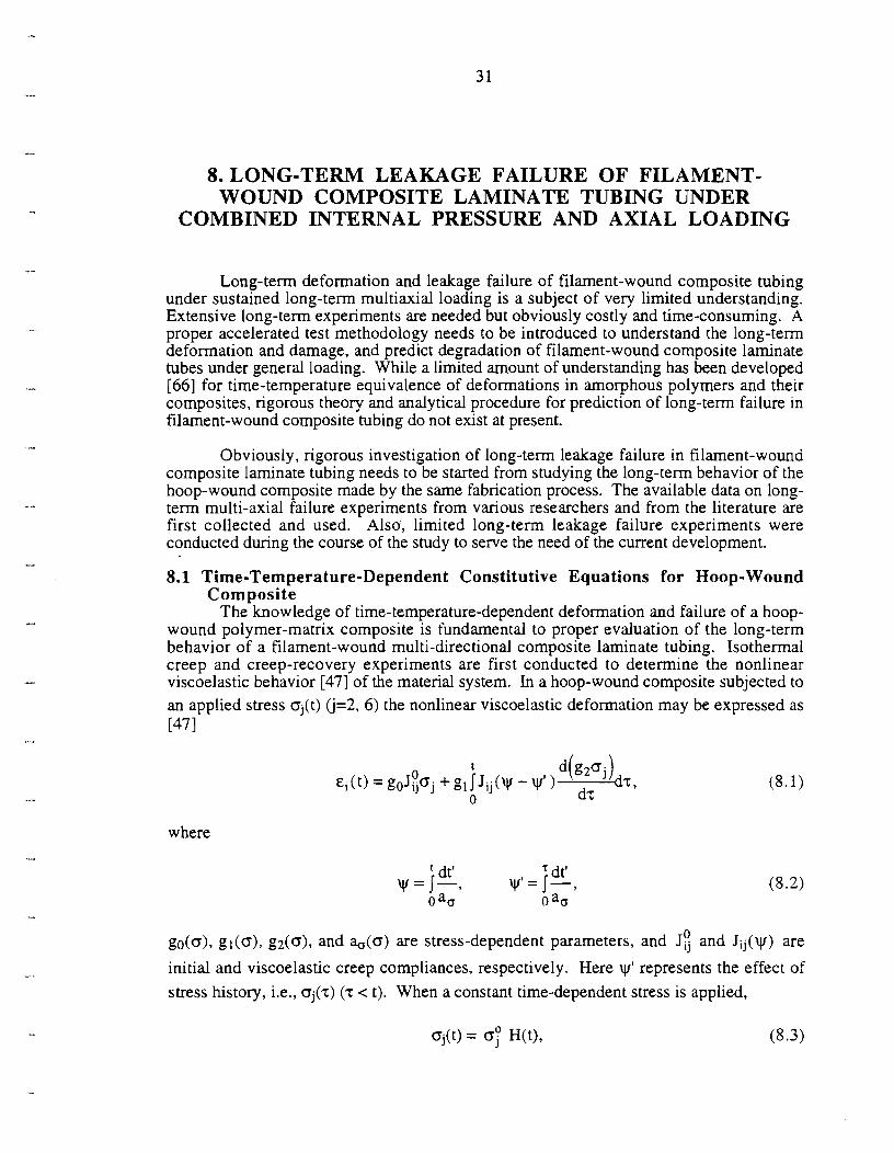
8. LONG-TERM LEAKAGE FAILURE OF FILAMENT- WOUND COMPOSITE LAMINATE TUBING UNDER
COMBINED INTERNAL PRESSURE AND AXIAL LOADING
Long-term deformation and leakage failure of filament-wound composite tubing under sustained long-term multiaxial loading is a subject of very limited understanding. Extensive long-term experiments are needed but obviously costly and time-consuming. A proper accelerated test methodology needs to be introduced to understand the long-term deformation and damage, and predict degradation of filament-wound composite laminate tubes under general loading. While a limited amount of understanding has been developed [66] for time-temperature equivalence of deformations in amorphous polymers and their composites, rigorous theory and analytical procedure for prediction of long-term failure in filament-wound composite tubing do not exist at present.
Obviously, rigorous investigation of long-term leakage failure in filament-wound composite laminate tubing needs to be started from studying the long-term behavior of the hoop-wound composite made by the same fabrication process. The available data on long- term multi-axial failure experiments from various researchers and from the literature are first collected and used. Also, limited long-term leakage failure experiments were conducted during the course of the study to serve the need of the current development.
8.1 Time-Temperature-Dependent Constitutive Equations for Hoop-Wound Composite
The knowledge of time-temperature-dependent deformation and failure of a hoop- wound polymer-matrix composite is fundamental to proper evaluation of the long-term behavior of a filament-wound multi-directional composite laminate tubing. Isothermal creep and creep-recovery experiments are first conducted to determine the nonlinear viscoelastic behavior [47] of the material system. In a hoop-wound composite subjected to an applied stress oj(t) 0=2, 6) the nonlinear viscoelastic deformation may be expressed as [47 I
where
' dt' dt' w = I-, w l = I-, 0 am 0 am
go(o), gl(o), g2(o), and ado) are stress-dependent parameters, and J: and J i j (y) are
initial and viscoelastic creep compliances, respectively. Here iy' represents the effect of stress history, i.e., o j ( ~ ) (z < t). When a constant time-dependent stress is applied,


where H(t) is the Heaviside step function and 0; is the magnitude of the applied stress, Eq. (8.1) may be expressed as
The creep compliance of a viscoelastic material may be approximated by various forms, e.g., a Prony series [84] or a power law expression [47]. For a glasslepoxy composite, the creep compliance, Jij, has been given [47] in a power law form as
where v=(glg2t I%), n is the power law exponent, and CL is a constant. From Eqs. (8.4)
and (8.5) the Sij(t,oj) can be expressed as
0 The go(oj) Jij may be determined from isothermal short-term experiments, and gl(oj),
g2(oj), %(aj), and n are obtainable from creep and recovery experiments [47]. The determination of a complete nonlinear viscoelastic behavior requires a series of studies at several stress levels to describe its stress dependency. The uniaxial compliance given by Eq. (8.6) may be generalized to the isothermal biaxial creep problem in an orthotropic fiber composite as
where Oj (k= 2, 6) represents the applied stress. To account for stress interactions when multiaxial loading is applied or the applied loading is not along the principal material directions, the viscoelastic compliances Sij and, consequently, the nonlinear parameters gi and %, may be expressed as functions of the 'average octahedral shear stress' To,, [47].
8.2 Time-Temperature-Dependent Failure for Hoop-Wound Composite
8.2.1 Kinetic model for matrix-dominated cracking in hoop-wound composite The kinetic failure model [58] for matrix-dominated cracking in a polymer
composite is based on molecular bond rupture kinetics of polymer matrix. Under an applied stress, o, the time to failure tf of a polymer may be expressed in a rate form [58],


where to is a constant, AH(a)t is the effective bond-rupture energy barrier, R is the Boltzmann's constant, and T is the absolute temperature . From Eq. (8.8), one has
T (log tf + C) = AH(o)/R = f(o), (8.9)
where C = -log(b). A strain-based failure function F(E) may be preferred in Eq. (8.9) in some cases when the constitutive equations are known. w l e extensive interpretation and application of Eq. (8.9) have been made to polymers, it has also been attempted for creep rupture studies of unidirectional graphitelepoxy [60], and for developing a time- temperature-dependent composite failure function [77], in which transverse and shear strengths Xi of a unidirectional graphitelepoxy composite are assumed to follow Eq. (8.9). In a filament-wound composite tubing, ply-level stresses Oi (i=1,6) are generally in a multiaxial stress state. The form of Eq. (8.9) allows for the ply-level multiaxial stress state to be considered. Thus, a relationship between the matrix-dominated failure function and the time to failure at different temperatures may be obtained.
8.2.2 Long-term leakage-failure criteria for filament-wound composite laminate tubing Leakage of the fiber-composite tubing under combined internal pressure and axial
loading may be attributed to matrix cracks formed through individual plies of the composite tubing wall. Accordingly, matrix-dominated ply failure criteria are needed to evaluate the long-term leakage failure. Due to the time-dependent deformations in the tubing plies, the failurz criteria may be conveniently expressed in terms of ply strains. Based on the failure experiments of hoop-wound composites conducted in this study, the following long-term matrix-dominated failure criteria are used: (a) Matrix-dominated ply transverse tensile failure [~2(t,T) + c3(t,T) > 01:
where A and B are material parameters obtainable from experiments. In this study, A and B are determined from short-term experiments of leakage failure in the [(+55")12 tubes, as discussed in Appendix B. (b) Matrix-dominated ply shear failure [EZC(t,T) < e2(t,T) < 01:
t AH(a) is assumed td be independent of temperature within the temperature range considered.

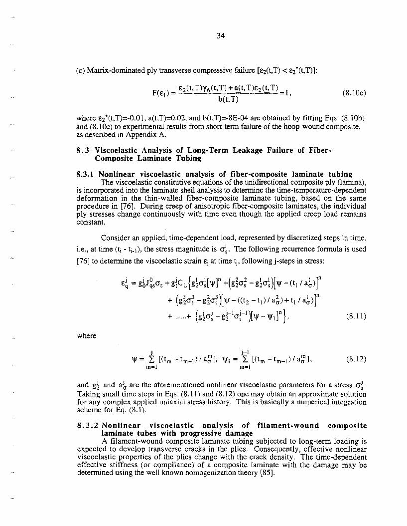
(c) Matrix-dominated ply transverse compressive fdure [c2(t,T) < c2*(t,T)]:
where ~~*(t,T)=-O.ol, a(t,T)=0.02, and b(t,T)=-8E-04 are obtained by fitting Eqs. (8. lob) and (8.10~) to experimental results from short-term failure of the hoop-wound composite, as described in Appendix A.
8 . 3 ViscoeIastic Analysis of Long-Term Leakage Failure of Fiber- Composite Laminate Tubing
8.3.1 Nonlinear viscoelastic analysis of fiber-composite laminate tubing The viscoelastic constitutive equations of the unidirectional composite ply (lamina),
is incorporated into the laminate shell analysis to determine the time-temperature-dependent deformation in the thin-walled fiber-composite laminate tubing, based on the same procedure in [76]. During creep of anisotropic fiber-composite laminates, the individual ply stresses change continuously with time even though the applied creep load remains constant.
Consider an applied, time-dependent load, represented by discretized steps in time, i.e., at time (ti - ti-l), the stress magnitude is 0:. The following recurrence formula is used
[76] to determine the viscoelastic strain cj at time tj, following j-steps in stress:
where
and g$ and ad are the aforementioned nonlinear viscoelastic parameters for a stress oj. Taking small time steps in Eqs. (8.11) and (8.12) one may obtain an approximate solution for any complex applied uniaxial stress history. This is basically a numerical integration scheme for Eq. (8.1).
8 . 3 . 2 Nonlinear viscoelastic analysis of filament-wound composite laminate tubes with progressive damage A filament-wound composite laminate tubing subjected to long-term loading is
expected to develop transverse cracks in the plies. Consequently, effective nonlinear viscoelastic properties of the plies change with the crack density. The time-dependent effective stiffness (or compliance) of a composite laminate with the damage may be determined using the well known homogenization theory [85].


Governing equations, material constitutive laws, and kmematic relationships for a unit cell may be expressed as
kkl(x,y oij(x,y;t) = 1 ciju(x9y;t-r) aT aT, and
where x and y are the global and local coordinates associated with the unit cell and Cijkl are the time-dependent stiffnesses of the composite. For the case of a composite tubing with transverse craclung, the compliance of the composite ply with damage may be expressed as
where the tilda denotes effective nonlinear viscoelastic properties as a function of the crack decsity (or damage Dij). A viscoelastic analysis procedure for long-term deformation of a filament-wound composite laminate tubing with progressive damage may be implemented with the above formulation in a time-stepping, incremental-iterative numerical algorithm.


9. DEVELOPMENT OF COMPUTATIONAL ALGORITHMS FOR LEAKAGE FAILURE OF FILAMENT-WOUND
COMPOSITE LAMINATE TUBING
9 . 1 Incremental-Iterative Algorithm for Progressive Damage and Degradation
The short-term leakage failure in a filament-wound composite laminate tubing is analyzed on a ply-by-ply basis with an incremental-iterative algorithm developed in this study. The computational mechanics procedure is outlined as follows: (1) Stresses and deformations in individual plies of a filament-wound composite laminate
tubing due to applied loads are determined first to evaluate initial matrix-dominated ply failure, using the aforementioned mechanism-based failure functions.
(2) Following the initiation of transverse cracks in the damaged plies, an iterative solution procedure, based on the aforementioned damage mechanics, is introduced. The procedure is given as follows: (a) The stiffnesses of the damaged composite plies are replaced with the degraded
- stiffnesses Sij discussed in Sec. 6.1 1.
(b) The redistribution of ply stresses are determined by the method outlined in Sec. 5.2.
(c) The aforementioned failure criteria are checked with the redistributed ply stresses. This step is completed when the stress redistribution does not cause any further ply failure.
(d) When computations in Steps (a), (b) and (c) are completed at the level of the currently applied load, the load is incremented and the damage mechanics based procedure is repeated.
A flow chart of the incremental-iterative algorithm is shown in Fig. 9.1. The analysis is terminated when the leakage-failure criteria (Sec. 9.3) are met. Details of the incremental nonlinear analysis are described in the next section.
9 . 2 Incremental Stress and Deformation Analyses during Progressive Damage
For any load increment, it is necessary to determine the portion of the induced incremental stresses which are elastic and the part which produces a change in the crack density. The latter must be determined from the post-failure portion of the stress increment. The ply stresses 0 2 and 0 6 are calculated as follows:


Step 1
Step 2
Step 3
Step 4
Step 5
Compute the incremental stress at the (i+l)th load increment, assuming the current stiffness as doq = E&hF+') . This may introduce errors if the ply has failed in the current load increment. However, any discrepancy will be corrected in the iterative scheme. The total ply stresses in the material coordinates are calculated as
o!+" = o!) +doq. The stresses, o!), are the converged values for the ith load increment. This step depends on whether or not matrix-dominated failure is initiated.
Check if the ma&-dominated failure criteria ~(0:~) L 1 are met.
1) If true, the ply fails during the application of do,. The portion of the stress component outside the failure envelope &st be reduced to the level at the failure surface. The reduction factor, Rf, is evaluated from
the equation ~ ( o g ) + Rf doq ) 5 1. Th~s yields a quadratic equation in Rf, which can then be computed. 2) If false, the ply is loaded elastically, and proceed with Step 6 For the failed plies only, compute the portion of the total stress which satisfies the failure function with o!+l) = 0:) + Rfdoq. The second term accounts for the portion of the stress increment occurring before the onset of current failure. The remaining portion of the stress increment, (1-Rf)do,, causes an increase in crack density, and has to be reduced to the failuresurface. The decrease in crack spacing ds can be determined from Eqs. (6.11 a) and (6.1 lb) as
where dD= -hds/s2. Step 6 For plies with elastic loading only the corrected stress is obtained as
= og) + do,. q
9 . 3 Algorithm for Leakage-Failure Determination for Filament-Wound Composite Laminate Tubes
Leakage failure in a fiber-composite laminate tubing occurs when a network of intralarninar (fiber failure and matrix-dominated cracks) and interlaminar (delamination) cracks is formed through the tubing wall thickness. Since transverse and shear strengths of a fiber composite ply are much lower than the longitudinal strength, leakage in a composite tubing is assumed to be caused by the initiation and growth of transverse cracks through the tubing wall. Considering the axisymrnetric nature of the composite tubing geometry and the applied loading, the leakage failure can be properly defined in this study. In the case of a tubing with matrix-dominated ply failure an intralaminar transverse crack is formed parallel to the fibers running all around the circumference of the tubing. Leakage starts when at least one intralarninar crack exists in each of the individual plies. That is, the matrix-dominated ply failure functions F(k) satisfy

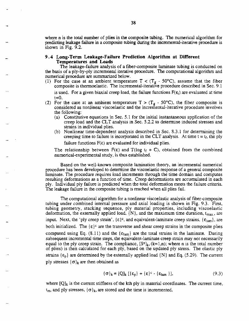
where n is the total number of plies in the composite tubing. The numerical algorithm for predicting leakage failure in a composite tubing during the incremental-iterative procedure is shown in Fig. 9.2.
9 . 4 Long-Term Leakage-Failure Prediction Algorithm at Different Temperatures and Loads
The leakage-failure analysis of a fiber-composite laminate tubing is conducted on the basis of a ply-by-ply incremental iterative procedure. The computational algorithm and numerical procedure are summarized below. (1) For the case at an ambient temperature T < (Tg - 50°C), assume that the fiber
composite is thermoelastic. The incremental-iterative procedure described in Sec. 9.1 is used. For a given biaxial creep load, the failure functions F(q) are evaluated at time t=O. For the case at an ambient temperature T > (Tg - 50°C), the fiber composite is considered as nonlinear viscoelastic and the incremental-iterative procedure involves the following: (a) Constitutive equations in Sec. 5.1 for the initial instantaneous application of the
creep load and the CLT analysis in Sec. 5.2.2 to determine induced stresses and strains in individual plies.
(b) Nonlinear time-dependent analysis described in Sec. 8.3.1 for determining the creeping time to failure is incorporated in the CLT analysis. At time t = tf, the ply failure functions F(E) are evaluated for individual plies.
The relationship between F(E) and T(1og tf + C), obtained from the combined numerical-experimental study, is thus established.
Based on the well-known composite lamination theory, an incremental numerical procedure has been developed to determine the viscoelastic response of a general composite laminate. The procedure requires load increments through the time domain and computes resulting deformations as a function of time. Creep deformations are accumulated in each ply. Individual ply failure is predicted when the total deformation meets the failure criteria. The leakage failure in the composite tubing is reached when all plies fail.
The computational algorithm for a nonlinear viscoelastic analysis of fiber-composite tubing under combined internal pressure and axial loading is shown in Fig. 9.3. First, tubing geometry, stacking sequence, ply material properties, including viscoelastic deformation, the externally applied load, (N}, and the maximum time duration, t,,,., are input. Next, the 'ply creep strain', (E)C, and equivalent-laminate creep strains, (E!,,}, are both initialized. The ( E ) C are the transverse and shear creep strains in the composite plies
computed using Eq. (8.1 1) and the (E~,,} are the total strains in the laminate. During subsequent incremental time steps, the equivalent-laminate creep strain may not necessarily equal to the ply creep strain. The compliance, [SeIk, (k=l,n); where n is the total number of plies) is then calculated for each ply, based on the updated ply stress. The elastic ply strains ( E ~ } are determined by the externally applied load ( N ) and Eq. (5.29). The current ply stresses (ojk are then obtained as
where [Qlk is the current stiffness of the kth ply in material coordinates. The current time, t,, and ply stresses, (o)k, are stored and the time is incremented.


The ply creep strains, (&IC, are determined; using the ply-stress history and the viscoelastic constitutive equations. Since the ply orientation and stress history vary from ply to ply, overall laminate compatibility may not be maintained in this step. The compatibility may be satisfied as follows. First the external load {N)C which would equal the ply strains are calculated from Eq. (5.23). The equivalent-laminate creep strain, {E~,,},
are then obtained from Eq. (5.29). The strains, are the predicted viscoelastic response of the laminate, based on the combination of the CLT and the viscoelastic constitutive equations. If the maximum time duration is not reached, the next time increment is carried out. When the maximum time is reached, failure function, F(ei(tmZ,T)), is determined and the nonlinear viscoelastic analysis is completed.


10. RESULTS AND DISCUSSION
10.1 Short-Term Leakage Failure Experiments on Filament-Wound Glass- FiberIEpoxy Composite Tubes
10.1.1 Multiaxial deformation and leakage-failure envelope Multiaxial load-controlled experiments were conducted to study deformations and
leakage failure of the two selected groups of filament-wound glasslepoxy compositc laminate tubes (Table 10.1). Fourteen experiments were conducted on [(k66°)2/(00)3/(f 66°)3/00]s glass/epoxy tubes at different combinations of internal pressure and axial tension. Typical load-deformation responses in the filament-wound composite tubes are given in Fig. 10.1. The ~h and E, are measured hoop and axial strains,
respectively, and oh and o, are average hoop and axial stresses applied through the tube cross section, respectively (i.e., o h = Rplt, o, = PIA, where R, t, and A are the mid- surface radius, wall thickness and cross sectional area of the tube respectively, and p and P are the applied internal pressure and axial load, respectively). The load-deformation curves were typically linear initially, followed by a "kink" and/or increased noise in strain signals with increasing loads, indicating individual ply cracking (or delarninations) during the load increase. The leakage-failure envelope of the filament-wound glasslepoxy composite tubes is determined from the experiments as shown in Fig. 10.2. A limited amount of data scatter is noted, as expected, especially for the cases with high hoop stresses. For the cases with approximately equal hoop-to-axial stress ratios, the leakage was observed at levels significantly lower than those of the composite tubes subjected to uniaxial or hoop stress alone.
Experiments were also conducted to study the effect of loading paths on the leakage failure of the [(f 66°)21(00)3/(k660)3/00]s composite under a combined internal pressure and axial tension. The experiments were designed for three loading-path cases: (a) high axial tension with low internal pressure, (b) medium axial tension and internal pressure, and (c) low axial tension with high internal pressure. The axial and hoop strains developed in the composite tubes under the proportional and nonproportional loading paths are shown in Fig. 10.3a. Note the difference between the strains caused by uniaxial (paths A and A') and biaxial (paths B and B') loading. The leakage-failure loads of the [(k66°)2/(00)3/(k660)3100]S composite tubes subjected to nonproportional loads are also compared with those under proportional loads. The effect of load path on leakage failure is shown in Fig. 10.3b. The results indicate that the difference in the leakage failure of the composite tubes subjected to different sequences of internal pressure and axial tension are not substantial for the composite tubing with the aforementioned layup.
Typical load-deformation responses obtained from the filament-wound [(f 55")12 glasslepoxy composite tubes are shown in Fig. 10.4. The [(65")12 tubes generally burst catastrophically at the point of leakage, i.e., the tubes lost their load-bearing capacities when leakage started. The composite tubes subjected to bi-axial loading with a high hoop stress failed by bursting, while those subjected to other load combinations exhibited matrix cracking through the tube walls at failure. The leakage failure envelope of the [(k55")I2 glasslepoxy tubes is presented in Fig. 10.5. The failure envelope is noted with higher leakage strengths for the cases under biaxial loads as compared to those under uniaxial

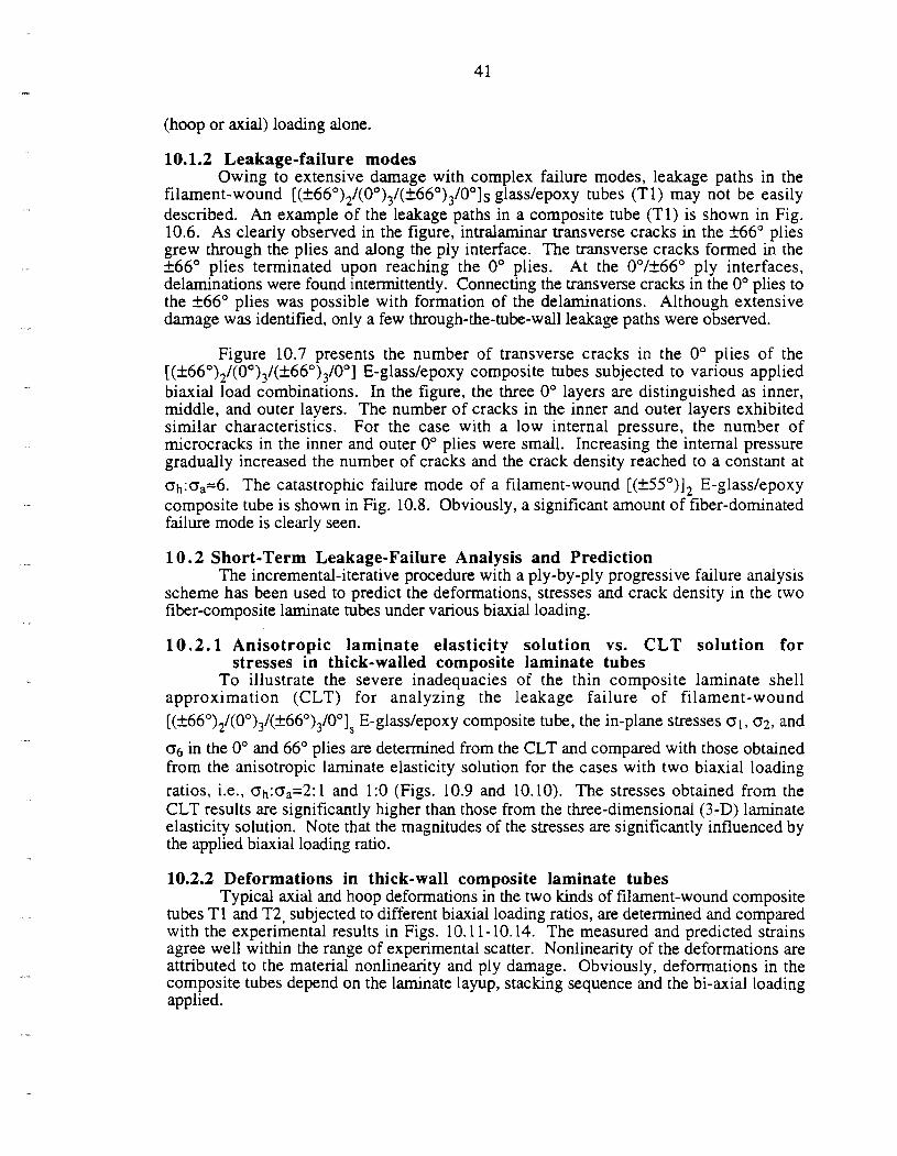
(hoop or axial) loarllng alone.
10.1.2 Leakage-failure modes Owing to extensive damage with complex failure modes, leakage paths in the
filament-wound [(+66°)2/(00)3/(+66")3/00]s glass/epoxy tubes (Tl) may not be easily described. An example of the leakage paths in a composite tube (TI) is shown in Fig. 10.6. As clearly observed in the figure, intralaminar transverse cracks in the f66" plies grew through the plies and along the ply interface. The transverse cracks formed in the +66" plies terminated upon reaching the 0" plies. At the 0°/f66" ply interfaces, delaminations were found intermittently. Connecting the transverse cracks in the 0" plies to the f66" plies was possible with formation of the delaminations. Although extensive damage was identified, only a few through-the-tube-wall leakage paths were observed.
Figure 10.7 presents the number of transverse cracks in the 0" plies of the [(+66°)2/(00)3/(+660)3/00] E-glass/epoxy composite tubes subjected to various applied biaxial load combinations. In the figure, the three 0" layers are distinguished as inner, middle, and outer layers. The number of cracks in the inner and outer layers exhibited similar characteristics. For the case with a low internal pressure, the number of microcracks in the inner and outer 0" plies were small. Increasing the internal pressure gradually increased the number of cracks and the crack density reached to a constant at oh:CJa=6. The catastrophic failure mode of a filament-wound [(f55")I2 E-glass/epoxy composite tube is shown in Fig. 10.8. Obviously, a significant amount of fiber-dominated failure mode is clearly seen.
1 0 . 2 Short-Term Leakage-Failure Analysis and Prediction The incremental-iterative procedure with a ply-by-ply progressive failure analysis
scheme has been used to predict the deformations, stresses and crack density in the two fiber-composite laminate tubes under various biaxial loading.
1 0 . 2 . 1 Anisotropic laminate elasticity solution vs. CLT solution for stresses in thick-walled composite laminate tubes
To illustrate the severe inadequacies of the thin composite laminate shell approximation (CLT) for analyzing the leakage failure of filament-wound [(~66°)2/(00)3/(f660)3/00]s E-glass/epoxy composite tube, the in-plane stresses al, 0 2 , and
06 in the 0" and 66" plies are detexmined from the CLT and compared with those obtained from the anisotropic laminate elasticity solution for the cases with two biaxial loading ratios, i.e., oh:oa=2:1 and 1:O (Figs. 10.9 and 10.10). The stresses obtained from the CLT results are significantly higher than those from the three-dimensional (3-D) laminate elasticity solution. Note that the magnitudes of the stresses are significantly influenced by the applied biaxial loading ratio.
10.2.2 Deformations in thick-wall composite laminate tubes Typical axial and hoop deformations in the two kinds of filament-wound composite
tubes TI and T2, subjected to different biaxial loading ratios, are detexmined and compared with the experimental results in Figs. 10.11- 10.14. The measured and predicted strains agree well within the range of experimental scatter. Nonlinearity of the deformations are attributed to the material nonlinearity and ply damage. Obviously, deformations in the composite tubes depend on the laminate layup, stacking sequence and the bi-axial loading applied.


10.2.3 Effect of material nonlinearity and loading bi-axiality ratio (a) Material nonlinearity
The transverse and shear stresses and strains developed in the outer ply of the filament-wound [( j~%")]~ E-glass/epoxy composite tubes subjected to an internal pressure are obtained from the incremental-iterative 3-D laminate elasticity analysis, (Fig. 10.15), using both linear and nonlinear shear constitutive equations discussed in Sec 5.1. Obviously, deformations and failure mechanisms could change significantly in the composite tubes depending on the magnitude of the internal pressure applied.
(b) Load biaxiality ratio The effect of applied biaxial loading ratio on the composite tube deformation and
failure is best illustrated by the ply stresses a;! and 0 6 developed in a [(?%")I2 composite tube subjected to different combinations of internal pressure and axial load. The solutions obtained from the 3D laminate elasticity theory with the incremental-iterative scheme, using the nonlinear shear deformation model, are presented in Fig. 10.16. The relatively linear responses for the cases with hoop-to-axial stress ratios from 0: 1 to 2.5: 1 indicate a lack of influence of the nonlinear shear for these cases. However nonlinear shear effects become significant on the ply stress development for the cases with applied hoop to axial ratios 3: 1 to 1 :O. Note that matrix-dominated failure predictions are governed by transverse tensior, and shear for the cases with applied hoop-to-axial loading ratios 0: 1 to 3: 1. For the cases of the biaxial loading ratios ranging from 3:l to 1:0, interactions between transverse compression and shear based mechanisms may govern the tube failure.
10.2.4 Leakage failure prediction (a) [ ( S 6 ")2/(0 0)3/(f 66 0)3/0 E-giass/epoxy composite tube Analytical predictions for f i r ~ t - ~ l y cracking and leakage failure in the composite
tubes T1 are shown in Fig. 10.17. The predictions are made by the use of the 3-D laminate elasticity solutions with the aforementioned ply damage mechanics formulation and ply failure criteria. The predicted failure envelope is noted to compare well with the experimental results for the cases with applied biaxial loading ratios containing high hoop stresses. The longitudinal (0°) plies fail first, and upon formation of transverse cracks in the +66" plies, a through-the-thickness leakage path is formed. In contrast, in the case with a high axial and a low internal pressure loading combination, the +66" plies are predicted to fail first and the 0" plies continue to take the load.
(6) [(f55 ")I2 E-giass/epoxy composite tube As discussed in Sec. 10.2.3, the nonlinear shear behavior in the composite ply
significantly affects stresses and deformations in the filament-wound composite tubes. The stacking sequence and the thin wall in the [(fi5")I2 E-glass/epoxy tubes warranted all the plies approximately in the same stress state. Consequently, formation of transverse cracks may occur in all the plies at about the same time during loading. Analytical predictions (using the 2-D method) for leakage failure of the [(k55")I2 glass/epoxy composite tubes under different combinations of internal pressure and axial tension are given in Fig. 10.18. It is interesting to note that the initial results from the analytical predictions are lower than the experimental data except for load combinations with very high hoop stresses. From Fig. 10.16, it is clear that the effect of nonlinear shear is small for biaxial load combinations at which the correlation between the analysis and experiments is poor. A further examination of the construction of the composite tube (Fig. 4.1) suggests that an outer layer of epoxy should be added in the composite layup. With the inclusion of the epoxy layer in the model, the predicted leakage failure envelope is in good agreement with the experimental results.


1 0 . 3 Long-Term Leakage Failure in Filament- Wound Glass/Epoxy Composite Tubes
10.3.1 Experimental results An attempt to develop an accelerated test method has been made in [78] to evaluate
long-term leakage in filament-wound composite tubes subjected to combined internal pressure and axial loading. The test results obtained in [78] together with those provided by the FRP tube manufacturers M1 and M2 are reviewed and used for the long-term leakage failure prediction in this study. We note that the long-term leakage experiments were conducted on filament-wound [(fi5")I2 glasslepoxy tubes at four temperatures, 75°F [74, 78, M1, M2], 131°F[78, M2], 150°F [MI], and 180°F [74]. At 75°F and 131°F, the tube failure was generally catastrophic in short loading durations [78]. However, under low applied loads, and consequently long times, failure was mainly due to leakage through the tube wall. The leakage path consisted of mainly transverse cracks connected by short delarninations [78]. Experimental data reported by manufacturer M1 at 75°F have a large scatter in failure time. These characteristics were not observed in the leakage experiments at 150°F.
10.3.2 Long-term leakage-failure analysis (Isothermal) Based on the kinetic failure theory discussed in Sec. 8.2.1, an analytical evaluation
of accelerated leakage experimental results has been made on the filament-wound [(fi5")I2 composite tubes subjected to combined internal pressure and axial tension. All the experiments reported here were for a bi-axial load ratio a h a , = 2: 1. Long-term leakage- failure data [74, 78, MI, M2] at four different temperatures are used to establish a functional relationship (Eq. (8.9)) between the matrix-dominated failure function and the time-temperature dependent leakage failure parameter. The relationship between the failure function, F(E), and the leakage-failure parameter, T*(logtf + C), is shown in Fig. 10.19, where the T* = T I Tg is a temperature normalized by Tq the glass transition temperature of the composite. Following the molecular theory of kine~c failure of an amorphous polymer [57], the constant C is taken as 20. Due to the simple lay-up of the filament-wound [(fi5")I2 composite, the function, F(&(t,T)), is approximately the same for all plies in the filament-wound composite tube.
From the figure, a well-behaved relationship between F(&(t,T)) and T*(logtf + C), may be established except for few data points. An approximately linear relationship may be established for all the cases at T = 75°F. The results shown in Fig. 10.19 from the leakage- failure data from [MI] at 150°F are also remarkably well behaved. Viewing the results, one may postulate that a different mechanism may be possible for the leakage failure at elevated temperatures. The long-term leakage-failure mode [MI] at elevated temperatures was observed to be weepage in the tube, in contrast to the catastrophic burst failure mode observed at room temperature.


1 1 CONCLUSIONS
1 . Microscopic examinations of failed samples from the leakage failure experiments reveal that at the onset of leakage failure in a filament-wound glass/epoxy composite laminate tube, the major leakage failure mechanism involves initiation, growth and coalescence of matrix-dominated transverse ply cracks, and in some case with a small amount of delamination, to form a leakage path through the tube wall.
2. Formation of the matrix-dominated transverse cracks in a filament-wound composite laminate tube is governed by a set of composite ply failure criteria (or functions) which can be determined from hoop-wound composite tubes under combined torsion and axial loading, as discussed in Appendix 1.
3. Dependent upon the composite laminate lay-up and the composite constituent materials, the short-term leakage failure envelope for a filament-wound composite tube, expressed in the (0,-ah) stress space, may have a either concave shape, such as the one for the
[(k66°)~/(00)~/(+660)~/00]s E-glass/epoxy, or a convex shape, such as the case for
4. The leakage failure in a typical FRP downhole tubing under combined internal pressure and axial loading, such as the case of a thick-wall, filament-wound [(+66")2/(0°)2/(k66")3
/O0Is E-glass/epoxy, may occur long before load-bearing structural (or burst) failure, whereas in a commonly used thin-wall FRP line pipe, such as the filament-wound [(k55")]2 E-glass/epoxy, under the same biaxial loading leakage failure usually occurs close to the tubing burst failure.
5. Under combined internal pressure and axial loading the leakage failure resistance of a filament-wound composite downhole tubing (i.e., the [(+66°)2/(00)2/(+660)3/00]s E- glass/epoxy), is lower than those of the tubing subjected to pure axial loading or hoop loading alone, whereas the opposite is observed for the FRP line pipe, i.e., ([(+55')]2 E- glass/epoxy).
6. The currently recommended interpolation procedure of the proposed API FRP tube- body ranking method for construction of a short-term leakage failure envelope, which is based on the assumption that all the composite tubing have smooth quadratic convex leakage-failure envelopes, appears to be inadequate to address some of the commonly used FRP downhole tubing, such as the [(+66°)2/(00)2/(+660)3/00]s E-glass/epoxy tubi ng, which have concave leakage-failure envelopes.
7 . For the composite tubing with a highly distorted leakage failure envelope, such as the case of a [(k55")]2 E-glass/epoxy tubing, the currently proposed weighting method and the recommended API procedure for constructing the short-term leakage failure envelope, which makes use of the tube-body test data from experiments with five uniformly dispersed biaxial hoop-to-axial stress ratios, i.e., 1:0, 2: 1, 1: 1 , 1:2 and 0: 1 , is not suitable. and the


selected biaxial stress ratios and their numbers are obviously not adequate to cover the highly distorted failure region.
8. For a thick-wall [ (+66°)~/(00)~l(+660)~100]s E-glasslepoxy downhole tubing subjected to a combined internal pressure and axial loading, the effect of the applied pressure and axial load paths on its short-term leakage failure does not seem to be appreciable as the differences in their leakage failure loads result from the various load paths are within the range of common experimental data scatter.
9. Based on the analytical methods developed in this study, accurate predictions of the short-term leakage failure envelopes can be made for both thick- and thin-wall filament- wound composite tubing, provided that the following information are available: (a). Nonlinear material constitutive properties of hoop-wound composites, especially the shear properties; and (b). Physical-mechanism-based failure criteria of the hoop-wound composite under combined internal pressure and axial loading.
10. In the long-term leakage failure study, failure modes are found to be different from those observed in the short-term leakage experiments for the filament-wound [(+55O)]2 E- glasslepoxy tubing, due to, at least, the following reasons: (a). creep deformations and stress relaxation in the polymer composite, especially the matrix-dominated deformations, and transverse and shear stresses; (b). long-term property degradation of constituent materials, i.e., fibers, the polymer matrix and the interface, in the composite, especially in high-temperature accelerated tests; (c). evolution of transverse cracks and associated stress redistribution during long-term loading.
1 1 . Except for the limited cases studied in the authors' laboratory, all the long-term leakage failure experiments reported have been on FRP tube bodies under a 2: 1 biuial loading ratio, and no clearly defined functional relationship among the failure time, biaxial loading and temperature could be properly established from the results.
12. The API proposed procedure for evaluating the long-term downhole FRP tubing failure, which is based on extrapolating the short-term leakage failure envelope with two additional (oh: oa= 2: 1 and 0: 1) long-term tube-body tests, does not include all these important considerations, besides all the aforementioned shortcomings in construction of the short-term leakage failure envelope, and may lead to results irrelevant to the actual long- term leakage failure behavior of the composite tubing.
13. Systematic tests to establish long-term leakage failure envelopes for evaluation and ranking of fiber composite laminate tubing are recognized to be very time consuming and expensive because of the time required and the large number of test variables involved. The need of an accelerated test methodology and associated life prediction methods for this purpose is obvious.
14. The proposed long-term leakage failure theory for the fiber composite laminate tubing under combined loading, based on the aforementioned hnetic fracture of polymer composites and the nonlinear viscoelastic composite mechanics, together with few selected accelerated tests at different temperatures should be adequate to establish the needed leakage failure functional relationship among long-term failure time, applied biaxial loading, test temperature and the composite lamination parameters.


12. REFERENCES
(1) Williams, J. G., 199 1, "Developments in composite structures for the offshore oil industry," OTC 6579, Proceedings of the 23rd Annual OTC, May 6-9, Houston, TX, pp. 165-178.
(2) Daniel, I. M., and Ishai, O., 1994, Engineering Mechanics of Composite Materials, Oxford University Press, New York.
(3) Swanson, S. R., Messick, M. J., and Tian, Z., 1987, "Failure of carbodepoxy lamina under combined stress," Journal of Composite Materials, Vol. 2 1, pp. 6 19- 630.
(4) Wang, S. S., Srinivasan, S., Karayaka, M., and X. Lu, 1994, "Long-term multiaxial strength of fiberglass tubing," Annual Research Report to API C-15 Committee, American Petroleum Institute, Waslungton, D. C.
(5) Hahn, H. T., and Tsai, S. W., 1973, "Nonlinear elastic behavior of unidirectional composite laminae," Journal of Composite Materials, Vol. 7, pp. 102- 1 18.
(6) Hashin, Z., Bagchi, D., and Rosen, B. W., 1974, "Nonlinear behavior of fiber composite laminates," NASA CR 2313, Washington, D. C.
(7) Swanson, S. R., Messick, M., and Toombes, G. R., 1985, "Comparison of torsion tube and Iosipescu in-plane shear test results for graphitelepoxy," Composites, Vol. 16, pp. ,220-224.
(8) Rowlands, R. E., 1984, "Strength (failure) theories and their experimental correlation," Failure Mechanics of Composites, Sih, G. C. and Skudra, A. M. Eds., North-Holland, New York, pp. 7 1 - 126.
(9) Sandhu, R. S., 1972, "A survey of failure theories of isotropic and anisotropic materials, U. S. Air Force Technical Report No. AFFDL-TR-72-71, Wright Patterson AFB, OH.
(10) Nahas, M. N., 1986, "Survey of failure and post-failure theories of laminated fiber-reinforced composites," Journal of Composites Technology and Research, Vol. 8, NO. 4, pp. 138-153.
(1 1) Azzi, V. D., and Tsai, S. W., 1965, "Anisotropic strength of composites," Experimental Mechanics, Vol. 5, No. 9, pp. 283-288.
(12) Tsai, S. W., and Wu, E. M., 1971, "A general theory of strength for anisotropic materials," Journal of Composite Materials, Vol. 5, pp. 58-80.
(13) Norris, C. B., 1939, "The elastic theory of wood failure," Transactions of the ASME, Vol 6 1, pp. 259-26 1.

(14) Puck, A. and Schneider, W., 1969, "On failure mechanisms and failure criteria of filament-wound glass-fiberjresin composites," Plastics and Polymers, pp. 33-44.
(15) Christensen, R. M., 1988, "Tensor transformations and failure criteria for the analysis of fiber composite materials," Journal of Composite Materials, Vol. 22, pp. 874-897.
(16) Hahn, H. T., Eriksson, J. B., and Tsai, S. W., 1982, "Characterization of matrix interface-controlled strength of unidrectional composites," Fracture of Composite Materials, Sih, G. C., and Tamuzs, V. P., Eds., Martinus Nijhoff, pp. 197-2 14.
(17) Hashin, Z., 1980, "Failure criteria for unidirectional fiber composites," Journal of Applied Mechanics, Vol. 47, pp. 329-334.
(18) Skudra, A. M., 1984, "Micromechanics of failure of reinforced plastics," Failure Mechanics of Composites, Sih, G. C. and Skudra, A. M., Eds., North-Holland, New York, pp. 1-68.
(19) Daniel, I. M., 1984, "Methods of testing composite materials," Failure Mechanics of Composites, Sih, G. C. and Skudra, A. M., Eds., North-Holland, New York, pp. 277-374.
(20) Forster, R. and Knappe, W., 1971, "Experimental and theoretical investigations on the crack formation limits for two-layer filament-wound glass-fiber-reinforced plastics tubes under internal pressure," KunststofSe, Vol. 61, pp. 583-588.
(21) Hull, D., Legg, M. J., and Spencer, B., 1978, "Failure of glass/polyester filament wound pipe," Composites, pp. 17-24.
(22) Soden, P. D., Kitching, R., Tse, P. C., Tsavalas, Y., and Hinton, M. J., 1993, "Influence of winding angle on the strength and deformation of filament wound composites tubes subjected to uniaxial and biaxial loads," Composites Science and Technology, Vol. 46, pp. 363-378.
(23) Ellyin, F., Kujawski, D., and Culen, M. S., "Fatigue behavior of pressurized filament wound fibreglass/epoxy tubes," Fatigue and Fracture, Proceedings of International Conference on Composite Materials, (ICCM- lo), August 14- 18, Whistler, Canada, Poursartip, A. and Street, K, Eds., Vol. 1, pp. 641-648.
(24) Chen, A. S., and Matthews, F. L., 1993, "A review of multiaxial/biaxial loading tests for composite materials," Composites, Vol. 24, No. 5, pp. 395-406.
(25) Jones, M. L. C. and Hull, D., 1979, "Microscopy of failure mechanisms in filament -wound pipe," Journal of Materials Science, Vol. 14, pp. 165- 174.
(26) Jones, R. M., 1975, Mechanics of Composite Materials, Scripta Book Co., Washington D. C.
(27) Whitney, J. M., and Halpin, J. C., 1968, "Analysis of laminated anisotropic tubes under combined loading," Journal of Composite Materials, Vol. 2, No., 3, pp. 360-367.
(28) Whitney, J. M., 1971, "On the use of shell theory for determining stresses in composite cylinders," Journal of Composite Materials, Vol. 5, No. 3, pp. 340-353.


(29) Lekhnitskii, S. G., 1981, Theory of Elasticiry of an Anisotropic Body, Mir Publications, Moscow.
(30) Pagano, N. J., and Whitney, J. M., 1970, "Geometric design of composite cylindrical characterization specimens," Journal of Composite Materials, Vol. 4, pp. 360-378.
(3 1) Roy, A. K., and Tsai, S. W ., 1987, "Design of thick composite cylinders," Design and Analysis of Composite Material Vessels, Presented at the Pressure Vessels and Piping Conference, June 28 - July 2, San Diego, California, D. Hui, and T. J. Kozik, Eds., PVP Vol. 121, pp. 75-85.
(32) Byon, 0-1, and Vinson, J. R., 1991, "Stress analyses of laminated thick-walled cylindrical anisotropic shells," AIAA Journal, Vol. 29, No. 12, pp. 2192-2196.
(33) Crossman, F. W. and Wang, A. S. D., 1982, "The dependence of transverse crachng and delamination on ply thickness in graphitelepoxy laminates," Damage in Composite Materials: Basic Mechanisms, Accumulation Tolerance and Characterization, Reifsnider, K. L., Ed., ASTM STP 775, pp. 118-139.
(34) Highsmith, A. L., and Reifsnider, K. L., 1982, "Stiffness-reduction mechanisms in composite laminates," Damage in Composite Materials: Basic Mechanisms, Accumulation Tolerance and Characterization, Reifsnider, K. L., Ed., ASTM STP 775, pp. 103- 117.
(35) Hahn, H. T., and Tsai, S. W., 1974, "On the behavior of composite laminates after initial failures," Journal of Composite Materials, Vol. 8, pp. 280-305.
(36) Reifsnider, K. L., 1977, "Some fundamental aspects of the fatigue and fracture resppnse of composite materials," Proceedings of the 14th Annual Society of Engineering Science Meeting, May 14-16, Lehigh University, Pa., pp. 373-384.
(37) Tan, S. C., and Nuismer, R. J., 1989, "A theory of progressive matrix cracking in composite laminates," Journal of Composite Materials, Vol. 23, pp. 1029- 1047.
(38) Daniel, I. M., and Lee, J. W., 1990, "Damage development in composite laminates under monotonic loading," Journal of Composite Technology and Research, Vol. 12, NO. 2, pp. 98-102.
(39) Tsai, C. L., and Daniel, I. M., 1992, "The behavior of cracked cross-ply composite laminates under shear loading," International Journal of Solids and Structures, Vol. 29, No. 24, pp. 3251-3267.
(40) Hahn, H. T., and Temple, R. C., 1993, "A mechanism-based constitutive equation for thick composite laminates with ply cracking," Mechanics of Thick Composites, Presented at the 1st Joint Mechanics Meeting of ASMEIASCEISES. June 6-9. Charlottesville, Virginia, Y. D. S. ~ a j a ~ a k s e y ~ d . , ASME, AMD ~ o l . 162, pp: 151-158.
(41) Laws, N., Dvorak, G. J. and Hejazi, M., 1983, "Stiffness changes in unidirectional composites caused by crack systems," Mechanics of Materials, Vol. 2, pp. 123- 137.


(42) Hashn, Z., 1986, "Analysis of stiffness reduction of cracked cross-ply laminates," Engineering Fracture Mechanics, Vol. 25, No. 5/6 pp. 771-778.
(43) Yuan, F. G., and Selek, M. C., 1993, "Transverse craclung and stiffness reduction in composite laminates," Journal of Reinforced Plastics and Composites, Vol. 12, No. 9, pp. 987-1015.
(44) Renard, J. and Thionnet, A., 1992, "Meso-macro approach to predict the damage evolution of transverse cracking in laminated composites," Damage Mechanics of Composites, Allen, D. H.and Lagoudas, D. C. Eds., ASME AMD Vol. 150, pp. 3 1-40.
(45) Ecknold, G. C., Leadbetter, D., Soden, P. D., and Griggs, P. R., 1978, "Lamination theory in the prediction of failure envelopes for filament wound materials subjected to biaxial loading," Composites, Vol. 9, pp. 243-246.
(46) Hinton, M. J., Soden, P. D., and Kaddour, A. S., 1995, "Strength of composite laminates under biaxial loads," Characterization and Ceramic Matrix Composites, Proceedings of International Conference on Composite Materials, (ICCM-lo), August 14-18, Whistler, Canada, Poursartip, A. and Street, K., Eds., Vol IV, pp. 65-72.
Lou, Y. C., and Schapery, R. A., 1971,' "Viscoelastic characterization of a nonlinear fiber-reinforced plastic," Journal of Composite Materials, Voi. 5, pp. 208-234.
Beckwith, S. W., 1975, "Viscoelastic characterization of a nonlinear glass/epoxy composite using micromechanics theory," JANNAF Operational Serviceability and Structures and Mechanical Behavior Working Groups - Combined Annual Meeting, CPIA Publication 264, pp. 27 1-296.
Yeow, Y. T., 1980, "Creep rupture behavior of unidirectional advanced composites," Materials Science and Engineering, Vol. 45, pp. 237-245.
Schapery, R. A., 1969, "On the characterization of nonlinear viscoelastic materials," Polymer Engineering and Science, Vol. 9, pp. 295-3 10.
Lifshitz, J. M., 1974, "Time-dependent fracture of fibrous composites," Composite Materials 5., Fatigue and Fracture, L. J. Broutman, L. J., and Krock, R. M., Eds., pp. 249-3 1 1.
Chiao, T. T., Lepper, J. K., Hetherington, N. W., and Moore, R. L., 1971, "Stress rupture of simple S-glass/epoxy composites," Journal of Composite Materials, Vol. 6, pp. 358-370.
Chiao, T. T., Sherry, R. J., and Hetherington, N. W., 19'17, "Experimental verification of an accelerated test for predicting the lifetime of organic fiber composites," Journal of Composite Materials, Vol. 11, pp. 79-9 1.
Otani, H., Phoenix, S. L., and Petrina, P., 1991, "Matrix effects on lifetime statistics for carbon fiber-epoxy microcomposites in creep rupture," Journal of Materials Science, Vol. 26, pp. 1955-1970.

(55) Knappe, W., and Schneider, W., 1972, "Fracture criteria for unidirectional glass fiberfplastic under even short-term and long-term stresses," KunststofSe, Vol. 62, pp. 864-868.
(56) Christensen, R. M. and Glaser, R. E., 1985, "The application of kinetic fracture mechanics to life prediction for polymeric materials," Journal of Applied Mechanics, Vol. 52, pp. 1-5.
(57) Goldfein, S., 1969, "Prediction techniques for mechanical and chemical behavior," Testing of Polymers, Vol. 4, Brown, W. E., Ed., John Wiley, New York.
(58) Zhurkov, S. N., 1965, "Kinetic concept of the strength of solids," International Journal of Fracture Mechanics," Vol. 1, No. 4, pp. 3 1 1-323.
(59) Wu, E. M., and Ruhmann, D. C., 1975, "Stress rupture of glass-epoxy composites: environment and stress effects," Composite Reliability, ASTM STP 580, pp. 263-287.
(60) Brinson, H. F., Griffith, W. I., and Morris, D. H., 1981, "Creep rupture of polymer-matrix composites," Experimental Mechanics, pp. 329-335.
(6 1) Daugste, C. L., 1974, "Joint application of time-temperature and time-stress analogies to constructing unified curves," Mechanics of Polymers, No. 3, pp. 427- 431.
Reiner, M., and Weissenberg, K., 1939, "A thermodynamic theory of the strength of materials," Rheology Leaflet, No. 10, pp. 12-20.
Hiel, C., Cardon, A. H., and Brinson, H. F., 1983, "The nonlinear viscoelastic response of resin matrix composite laminates," VPI and SU Report, VPI-E-83-6.
Evans, R. W., and Wilshire, B., 1993, Introduction to Creep, The Institute of Materials, London.
Arnold, J. C., and White, V. E., 1995, "Predictive models for the creep behavior of PMMA," Materiuls Science and Engineering Series A, Vol. 197, pp. 25 1-260.
Ferry, J. D., 1970, Viscoelastic Properties of Polymers, John Wiley and Sons, New York.
Griffith, W. I., Morris, D. H., and Brinson, H. F., 1980, "Accelerated characterization of graphitefepoxy composites," Advances in Composite Materials, Proceedings of International Conference on Composite Materials, (ICCM-3), Bunsell, A. R., Bathias, C., Marthenchan, A., Menkes, D., and Verchery, G., Eds., Permagon Press, pp. 461-47 1.
Brinson, H. F., Morris, D. H., Griffith, W. I., and Dillard, D. A., 1981, "The viscoelastic response for a graphitefepoxy laminate," Proceedings of the International Conference on Composite Structures," Marshall, I. H., Ed., Applied Science Publishers, pp. 285-300.
Bax, J., 1970, "Deformation behavior and failure of glassfiber-reinforced resin material," Plastics and Polymers, Voi. 37, pp. 27-30.


Mieras H. J. M. A,, 1973, "Irreversible creep of filament-wound glass-reinforced resin pipes," Plastics and Polymers, Vol. 41, pp. 84-89.
Crowther, M. F., Phillips, M. G., and Wyatt, R. C., 1985, "Design stress considerations for GRP components of power station cooling-water systems," Composite Structures 3, 1. H. Marshall, Ed., Elsevier Applied Science Publishers, London, U. K., pp. 540-561.
Greenwood, J. H., 1986, "Creep of glasslepoxy laminates at service temperatures," 5th BEAMA International Electrical Insulation Conference, May 19- 22, Brighton, U. K., pp. 205-209.
Sillwood, J. and Aveston, J., 1989, "Semi-empirical modeling of stress rupture data on glass reinforced plastics," Developments in the Science and Technology of Composite Materials, Third European Conference on Composite Materials, (ECCM3), 20-23 March, A. R. Bunsell, P. Larricq, and A. Massiah, Eds., Elsevier Applied Science, London, U. K., pp. 713-720.
Huntoon, G. G. and Alkire, J. D., 1989, "Design and performance properties of oilfield fiberglass tubulars," 64th Annuai Technical Conference and Exhibition of' the Society of Petroleum Engineers; October 8-1 1, San Antonio, TX, pp. 253-262.
Provost, E. T., 1993, "Extending the GRP option: A performance-based purchase specification for GRP pipes and fittings (based on API-15HRlAPI 15LR)," Proceedings of the 12th International Conference on Offshore Mechanics and Arctic Engineering, Glasgow, Scotland, pp. 167- 175.
Tuttle, M. E., and Brinson, H. F., 1'986, "Prediction of the long-term creep compliance of general composite laminates," Experimental Mechanics, Vol. 26, No. 1, pp. 89-102.
Dillard, D. A., Morris, D. H., and Brinson, H. F., 1982, "Predicting viscoelastic response and delayed failure in general laminated composites," Composite Materials: Testing and Design (Sixth Conference), ASTM STP 787, Daniel, I. M., Ed., pp. 357-370.
Payne, C., 1996, "Accelerated test methods and failure modes for long term leakage of fiber reinforced plastic composite tubulars subjected to combined internal pressure and axial loading," M. S. Thesis, Mechanical Engineering Department, University of Houston, Houston, TX.
Duvaut, G., 1976, "Analyse fonctionnelle et Mechanique des milieux continus application a l'etude des materiaux composites elastiques a structure periodique homogeisation," Theoretical and Applied Mechanics, Koiter, W. T., Ed., North- Holland Publishing Co., Amsterdam.
Bensousan, A., Lions, J. L., and Papanicolaou, 1978, Asymptotic Analysis for Periodical Structures, North-Holland, Amsterdam.
Lene, F., and Leguillon, D., 1982, "Homogenized constitutive law for a partially cohesive composite material," International Journal of Solids and Structures, Vol. 18, pp. 443-458.

(82) Shibuya, Y. and Wang, S. S., 1992, "A homogenization theory for fiber- composites with imperfect interface at elevated temperatures," Proceedings of the Sixth Japan-U. S. Conference on Composite Materials, June 22-24, Technomic Publishing Co., Inc., Lancaster, Pa., pp. 188- 197.
(83) Sun, C. T., and Li, S., 1988, "Three-dimensional effective elastic constants for thick laminates," Journal of Composite Materials, Vol. 22, pp. 629-639.
(84) Gramoll, K. C., Dillard, D. A., and Brinson, H. F., 1989, "A stable numerical solution method for in-plane loading of nonlinear viscoelastic laminated orthotropic materials," Composite Structures, Vol. 13, No. 4, pp. 25 1-274.
(85) Skontorp, A., 1995, "Isothermal high-temperature oxidation, aging and creep of carbon-fiberlpolyimide composites," Ph.D Dissertation, Mechanical Engineering Department, University of Houston, Houston, TX.
(86) Zweben, C., Hahn, H. T. and Chou, T. W., 1989, Mechanical Behavior and Properties of Composite Materials, Vol. 1, Technomic Publishing Co., Inc., Lancaster Pa, pp. 49-72.
(87) Miyase, A., Wang, S. S., Chen, A. W., L., and Geil, P. H., 1993, "Anelastic deformation of a thermoplastic-matrix fiber composite at elevated temperature; Part 11: Time-temperature dependent matrix behavior," Journal of Composite Materials, Vol. 27, No. 9, pp. 908-920.


13. FIGURES


0.00 I I 1 I 1 I -55" 55" -55" 55" epoxy outer layer
Fig 4.1 Ply-thickness t variations in E-glass/epoxy composite tubular specimens. (a) [(f 66"),/(0"),/(M6"),/0"],, and (b) [(k55")I2


- 4f*-4 Spacer
3 4.5 z (in.)
Fig. 4.2 Stress distributions in the outer 66" ply of a [(k66°)2/(00)3/(~660)3100]S E- glass/epoxy tubs~lar specimen subjected to internal pressure p


3 4.5 z (in.)
Fig. 4.3 Stress distributions in the outer 66" ply of a [(+,66°),/(00),/(+_660),/00], E-
glass/epoxy tubular specimen subjected to axial tension @


End tab
Composite specimen
Fig. 4.4 Geometry of a filament-wound E-glass/epoxy composite tubular specimen


Fig. 4.5 Schematic of the specimen and the grip system for biaxial experiments


SERVOHYDRAULIC LOAD FRAME
Leakage detection
-
-+POWER
4 COMPUTER CONTROL. DATA ACQUISITION
ELECTRONIC & LEAKAGE CONTROLLER ) DETECTION SYSTEMS
PRESSURE INTENSIFIER
Fig. 4.6 Test system schematic for leakage failure experiment of filament-wound composite laminate tubes subjected to combined internal pressure and axial loading


Fig. 5.1 Material coordinates for a unidirectional fiber composite


Fig. 5.2 Coordinates and lamination parameters of a filament-wound composite laminate tubing


Fig. 6.1 Composite laminate with tranverse crack


/ Input data / I
Apply load increment
Update ply stiffness
equilibrium
Compute ply stresses and deformations
oSFl Ply F(aj) 2 1 ?
eQ initiation?
no
Modify ply stresses
Update ply stiffness
Fig. 9.1 Incremental-iterative computational algorithm for leakage-failure analysis of filament-wound composite laminate tubing


Apply load increment
and strains
Ply F(k)(oj) 2 + Fig. 9.2 Numerical algorithm for predicting leakage failure in a composite tubing


Input data
I
Initialize creep strains
{ & I C = (017 (&)ply = 0
Update elastic ply compliance [SeIk
Compute instantaneous F ply strains { c p }
Compute current ply stresses
{ o ) k = [Qlk + { & I C - {&}p ly ]
Store current ply stresses and time { G } ~ , trn
Compute ply c creep strains ( & I C
I
Compute laminate creep load, strains ( N J C . { E }
Fig. 9.3 Incremental algorithm for nonlinear viscoelastic analysis of a composite laminate tubing subjected to internal pressure and axial loading.


n . 5 - V1 1 5 1 71 - - - - - gage 2 / = 10 /'
Fig. 10.1 Typical load-deformation response of filament-wound [(~6°)2/(00)3/(f660)3100]S
E-glasslepoxy composite tube subjected to biaxial loading (oh/oa = 1.0811) (a) axial, and (b) hoop stress-strain development


a,, (ksi)
Fig. 10.2 Leakage-failure envelope for filament-wound [(i66°)2/(00),/(~660)3/00]S E-glass/epoxy composite tubes subjected to combined internal pressure and axial tension

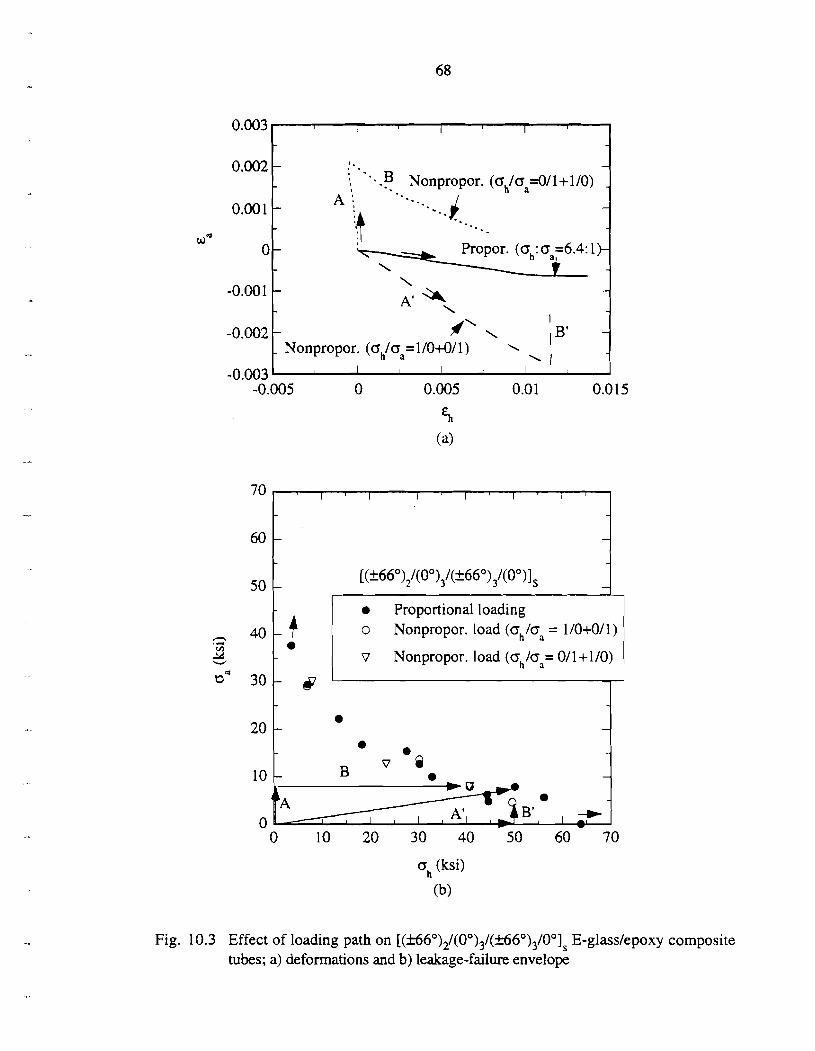
0.002
0.00:1
0 -
-0.001
-0.002
-0.003
0 10 20 30 40 50 60 70
ah (ksi)
(b)
- 1 . 8 .
- 0 - : '-.B Nonpropor. (~,,/,/q=011+1/0) -
A :, *.. - " =-..d - -. . . - -
\ Propor. (a,: aa=6.4: 1 )- i
\ - * - A' \
I - *' \ - - Nonpropor. (a,,/aa=llO+O/l) L I B'
' I I I 1
I ' l ' l ' l ' l ' i '
-
-
[(+66°),/(00),/(k660) 4(0°)] -
Fig. 10.3 Effect of loading path on [ (~6° )21(00)31(~60)3 /001s E-glasslepoxy composite tubes; a) deformations and b) leakage-failure envelope
-0.005 0 0.005 0.01 0.0 15
Eh (a)
A I . Proportional loading
o Nonpropor. load (a,/% = 110+0/1)
v Nonpropor. load (G,/G~= 011 +1/0)
dJ . - . . - B v Q . - . , +


Fig. 10.4 Typical load-deformation response of filament-wound [(+55")12 E-glass/epoxy composite tube subjected to hoop loading (oh/o, = 1/0); (a) axial, and (b) hoop strain development


Fig. 10.5 Leakage-failure envelope for filament-wound [(f E-glass/epoxy composite tubes subjected to combined internal pressure and axial tension

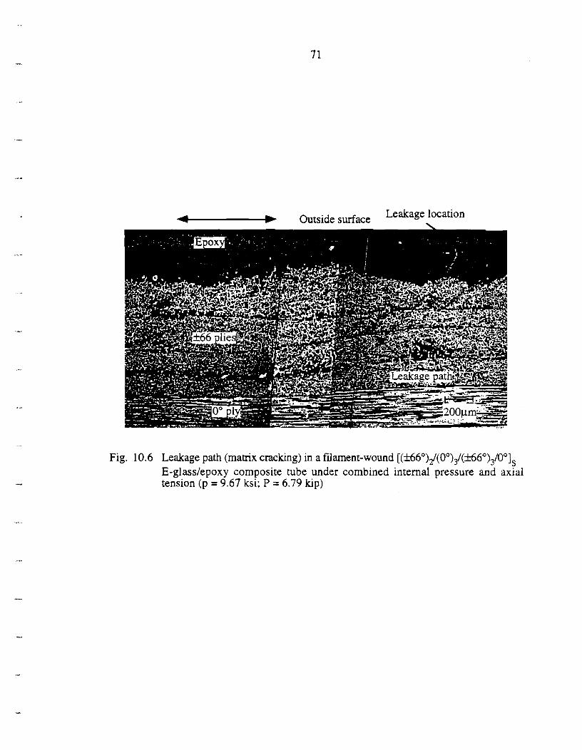
-I Outside surface Leakage location
Fig. 10.6 Leakage path (matrix cracking) in a filament-wound [(&66°)2/(O")3/(&660)3/00]s E-glass/epoxy composite tube under combined internal pressure and axial tension (p = 9.67 ksi; P = 6.79 kip)


Fig. 10.7 Transverse (ply) crack density in [(~66°)21(0")31(f 66")3/00]s E-glasslepoxy composite tubes subjected to combined internal pressure and axial tension


Fig. 10.8 Leakage failure of a filament-wound [(&.55")12 E-glass/epoxy composite tube under internal pressure (p = 2.97 ksi; P = 0)


Inner (0') ply
4 - 0, (3-D)
a, (ksi)
a, (ksi)
(b)
Fig.lO.9 Comparison of 3-D and CLT solutions for filament-wound [(~0),/(00)3/(lt660)3/00]s E-glass/epoxy composite tubes under internal pressure (p = 1.95 ksi; P = 0 )


a,, (ksi)
(a)
Fig.lO.10 Comparison of 3-D laminate and CLT solutions for filament-wound [(+,66°),/(00)3/(+_660)3/00]s E-glass/epoxy-composite tubes under internal pressure and axial tension (p = 1.95 ksi; P = 7.12 kip)


Fig. 10.1 1 Predictions and measured global load-deformation responses in filament- wound [(f 66°)2/(00)3/(k660)3/00]s E-glasslepoxy tribe under internal pressure and axial tension (a) axial and (b) hoop strains (p = 2.72 ksi; P = 18.4 kip )


Fig. 10.12 Predictions and measured global load-deformation responses in filament- wound [(+66°)2/(00),/(+660)3100]s E-glasslepoxy tube under internal pressure and axial tension (a) axial and (b) hoop strains (p = 9.02 ksi; P = 7.8 1 kip)


Fig. 10.13 Predictions and measured global load-deformation responses in filament- wound [(f E-glass/eposy tube under internal pressure and axial tension (a) axial (b) hoop strain (p = 0.06 ksi; P = 5.25 hp)


Fig. 10.14 Predictions and measured global load-deformation responses in filament- wound [(k55")l2 E-glass/epoxy tube under internal pressure and axial tension (a) axial and (b) hoop strains (p = 1.28 ksi; P = 5.83 kip)


- nonlinear shear model
0.02 1 I -- linear shear model 1 \ \ { - nonlinear shear model
Fig. 10.15 (a) Ply siresses and (b) strains in a filament-wound [(+55O)l2 E-glasslepoxy composite tube under increasing internal pressure (2-D CLT solution with increme~tal-iterative scheme).


o, (ksi)
Fig. 10.16 Ply stresses in a filament-wound [(fi5")I2 E-glass/epoxy composite tube under combined internal pressure and axial tension with different biaxial loading ratios


1 1 I Experimental data ~ - - - - A First ply failure prediction
- Leakage prediction (Linear shear model)
5 0 q - Leakage prediction (Nonlinear shear model)
oh (ksi)
Fig. 10.17 Leakage-failure envelope for filament-wound [(f 66°)2/(00)3/(f660),/00]s E- glasslepoxy composite tubes subjected to combined internal pressure and axial tension


A Experimental data - - Leakage prediction (Linear shear model) - Leakage prediction (Nonlinear shear model) - * - Leakage prediction
(Outer epoxy layer and nonlinear shear)
oh (ksi)
Fig. 10.18 Failure envelope for filament-wound [(k55")I2 E-glass/epoxy composite tubes subjected to combined internal pressure and axial tension


15 16 17 18 19 20 2 1 22
T* (log t,+C)
Fig. 10.19 Long-term leakage failure in filament-wound [(&55")l2 E-glass/epoxy composite tubes under combined internal pressure and axial loading


85
14. TABLES
Table 4.1 Composite laminate lay-up sequence and geometry of tubular specimen5
Laminate Lav-uu [ ( ~ 6 ° ) ~ ~ ~ 0 ~ 3 ~ ( ~ 6 0 ~ 3 ~ ~ 0 1 s (TI) [(+55O)12 (T2)
Inner Diameter (di) 1.94 in. 2.24 in.
Outer Diameter (&)
Tab Material
2.36 in.
E-glass/epoxy
2.40 in.
Woven fabric
Table 4.2 load in^ ratio and test temDeratures for lonp-term leakape experiments
Tests Test temperature ( O F ) Biaxial Loading ratio (04
S1 [74] 75, 180 2: 1
Table 10.1 Lay-up sequence and geometry of filament-wound elass/ewoxv-composite laminate tubes
Lamination (Tube Code) Tube Diamater Tube Thckness di (in.) L h J Tab
[(+55O)12 (T2) 2.24 0.08 Woven fabric


APPENDIX A
DEFORMATION AND FAILURE OF HOOP-WOUND GLASS- FIBER/EPOXY COMPOSITE SUBJECTED TO COMBINED
TORSION AND AXIAL LOADING
A series of multiaxial experiments have been conducted to determine deformation characteristics, failure modes and failure criteria of the hoop-wound E-glass/epoxy composite. The in-plane transverse and nonlinear shear stress-strain relationships and failure envelope of filament-wound E-glass/epoxy composites under various combined axial loading and torsion have been obtained. The hoop-wound tubular specimens provide the following advantages for the study: (1) Any state of combined axial and shear stresses can be obtained in the simplest and
most accurate manner. (2) Composite properties can be determined accurately in the tubular specimens made with
the same processing parameters for the composite laminate tubing. (3) Stress concentrations which occur in other specimen geometries, such as the Iospescu,
do not exist in the tubular specimens. The experimental set-up, specimen preparation and design, gripping system, data acquisition techniques, and experimental procedure are briefly summarized here. The results are used later for studying filament-wound composite laminate tubes under combined axial tension and internal pressure.
A . l Materials and Specimen Preparation Hoop-wound composite specimens (Fig. A. 1) were made up of E-glass/epoxy by a
filament-winding method. The composite tubes had a winding angle of +2" off the circumferential direction with a nominal inner diameter di = 1.91 in., outer diameter do = 2.35 in., and length = 15.5 in. Properly designed E-glass/epoxy tabs, also hoop-wound, were laid on the specimen for gripping and load transfer in the gripping region. The tabs were machined to desired dimensions and the gage section was maintained in an as- received condition. Burnout tests were conducted [4] on the composite to determine its fiber volume fraction (Vf) and void content. The average fiber volume fraction (measured from five samples) was 57% and the void volume fraction varied from 0.5%-3%.
A.2 Experimental Facilities The experimental facilities consist of a closed-loop servo-hydraulic multiaxial test
system with a combined pressure, and axial and torsional loading capacity. The pressure intensifier, and axial and torsional loading actuators are independently controlled. The composite tubular specimens could be subjected to various combinations of pressure, axial loading and torque. No pressure was applied in this study. The specimen ends with the tabs were clamped by the split flange grips described in Sec. 4. A biaxial extensometer was constructed [4] to measure simultaneously axial and shear deformations in the specimens under biaxial loading.
A.3 Data Acquisition A computer-controlled data acquisition system was developed to record the applied
axial load, torque, and position from the test machine, and the axial and shear deformations from the biaxial extensometer (and strain gages) mounted on the specimen. The strain


signals were processed through a combination of eight quarter and half Wheatstone bridges, and then stored in a microcomputer for subsequent analysis.
A.4. Experimental Method and Procedure Experiments were conducted on the hoop-wound tubular composite specimens
under various combinations of torsion and axial loading. The specimens were first subjected to axial stresses up to the prescribed levels. Then, shear stresses were added and monotonically increased until the specimens failed. In all experiments, axial loads and torques were applied at loading rates of 10 lblsec and 25 lb-in/sec, respectively.
A.5 Mechanical Behavior of Hoop-Wound E-gIass/Epoxy Composite
A.5.1 Composite Material Constitutive Relationships The response of the hoop-wound E-glasslepoxy tubes subjected to axial tension,
pure shear and axial compression are shown in Fig. A.2. Transverse and shear moduli for the composite are summarized in Table A. 1. The stress-strain behavior of the composite under transverse tension was fairly linear up to failure, while a significant amount of nonlinearity was exhibited during shear and compression deformations. Further, the shear failure strain was large, i.e., greater than 3%, for the E-glasslepoxy composite.
A nonlinear elastic constitutive model based on the complementary strain energy formulation [ 5 ] , has been developed to describe the nonlinear shear behavior?. The nonlinear shear constitutive equation of the composite may be expressed as
where Y6 is the engineering shear strain, and G66 (= 2 ~ : ~ ) and S6666, are linear and nonlinear shear properties, respectively. The S6666 for a E-glasslepoxy composite is obtained from the pure shear experiments Fig. A.3, using a curve-fitting technique.
A.5.2 Multiaxial Failure Envelope The transverse and shear strengths, obtained from the axial-torsion experiments, are
shown in Fig. A.4a. Note the distinct characteristics of the failure envelopes in the transverse tension-shear vs. the transverse compression-shear regions (depicted by regions I, 11, III in Fig. A.4a). Different failure mechanisms were observed, due to interactions among these stress components, which will be addressed in the next section. As has been noted by previous researchers (Sec. 2.1.2), a low transverse compression increases the shear strength considerably (Region 11), whereas a high compressive stress (Region 111) reduces the composite shear strength. A well defined failure envelope exists for the cases under combined transverse tension and shear (Region I). For comparison a strain-based failure envelope is also shown in Fig. A.4b. Failure strains exhibit a larger scatter than the failure stresses.
A.6 Failure Modes In order to understand the failure mechanisms in the composites, fractographic
studies were conducted on failed specimens, using a scanning electron microscope (SEM). For illustration, hoop-wound tubular specimens which were failed at five different combinations of transverse and shear loading were chosen.
- -
t In [ 5 ] , it is assumed that the degree of shear nonlinearity is not influenced by the transverse stress 0 2 .


Fracture surfaces of the specimen failed under transverse tension (Fig. A.5) depicts failure occurring at the fiber-matrix interface and through the brittle matrix. For a combined transverse and shear loading (Fig. A.6), the fracture surface appeared to be rough. As was the case for transverse loading, failure occured along fiber-matrix interfaces and through the matrix between fibers. Some limited deformations of the matrix was observed. Fracture surfaces of specimens subjected to pure shear (Fig. A.7), exhibited significant matrix deformation in addition to fiber-matrix interface failure. Significant crushing of the matrix and fiber debonding were observed on the fracture surfaces of the failed specimens under combined shear and compression (Fig. A.8), and uniaxial compression loading (Fig. A.9). The fracture plane was inclined to the axis of the tube (cup and cone fracture). In general, fiber-matrix interface debonding was a common failure mode in all cases studied. However, significant matrix deformations were also observed in the fracture surfaces of the specimens failed under combined transverse and shear loading.
Microscopic observations away from the specimen fracture surfaces revealed no microcracks. This indicates that nonlinearity in the deformations may not be caused by nucleation and growth of cracks.
A.7 Matrix-Dominated Multiaxial Failure Criteria As discussed in Sec. 7.2, Hashin's failure criteria [17] for matrix-dominated
fracture are evaluated (Fig. A.lO) with the failure envelope of the hoop-wound E- glasslepoxy-composite tubes obtained from the experiments. The matrix-dominated failure criteria in a 2-D plane-stress condition are given as follows: i) Matrix-dominated ply transverse tensile failure (02 > 0):
ii) Matrix-dominated ply transverse compressive failure (02 c 0):
In this study, X4 is assumed to be equal to the pure shear strength X6. Equation (A.2a) provides a good description for the region of combined transverse tension and shear failure. Equation (A.2b) does not represent accurately the matrix-dominated failure under combined transverse compression and shear. Similar to the expressions proposed in [18], the matrix-dominated failure in Regions I1 and 111 are assumed to be described by the principal stress criteria. Following the assumption of Hashin [17] that the fiber-direction stress ol does not influence the matrix-dominated failure, in a plane stress state (0-3 = 0 4 = os = 0) the principal stress based failure criteria may be expressed as
(a) Matrix-dominated ply shear failure, (Region a; o2 > Xz + X6):


(b) Matrix-dominated ply compressive failure, (Region ID; a2 < X? + X6):
where D2 and D3 are failure strengths along the principal material directions. For the hoop-
wound composites, D2 and D3 are selected to be X6 and XT, respectively.
Similarly, the following strain based matrix-dominated failure criteria (Fig. A. 11) are used to study failure of the hoop-wound E-glass/epoxy composite: (a) Matrix-dominated ply transverse tensile failure (€2 > 0)
(b) Matrix-dominated ply shear failure (c2* < €2 < 0):
We note that the strain-based criterion corresponding to Eq. (A.2d) does not accurately represent the matrix-dominated transverse compressive ply failure. Therefore the failure function for this case is expressed as (c) Matrix-dominated transverse compressive ply failure ( ~ 2 < s2*):
where E~*=-O.O~, a=0.02, and b=-8E-04 are parameters obtained by fitting Eqs. (A.3b) and (A.3c) to the experimental data.


APPENDIX B
TIME-TEMPERATURE-DEPENDENT MECHANICAL PROPERTIES OF HOOP-WOUND GLASS-FIBER/EPOXY
COMPOSITE
Effective material properties of the hoop-wound E-glass/epoxy composite have been obtained from the experiments. Stiffnesses and strengths of the hoop-wound composite are summarized in Table A.l in Appendix A with nonlinear shear properties being represented by a power law given in Eq. (5.2). The glass transition temperature, Tg, of the composite is 221°F [4], determined by DSC measurements.
B. l Materials and Specimen Preparation. Owing to the very limited number of hoop-wound composite tubes available,
unidirectional, E-glass/epoxy coupon specimens (Fig. B.l) were cut from the hoop-wound tubular specimens for experiments in this study. Sections of the hoop-wound tubes were machined on a lathe to an outer diameter 0.0625 in. greater than the gage section of the tubular specimens. The experiments were expected to determine accurately mechanical properties of the hoop-wound glass-fiber composite. Since the coupon specimens were carefully cut from cylindrical composite tubes they had a small curvature. The effect of the specimen curvature on the stress in the gage section was found to be negligible, using a three-dimensional finite element analysis. End tabs were hand laid on the specimen, using a HEXCEL 5 Harness satin woven cloth with an EPON 828 resin and an EPI-CURE 44 10 curing agent. The end tabs were then cured at 131°F for 12 hours and 75°F for 48 hours, and subsequently machined to possess flat parallel surfaces for gripping. Specimen edges were polished with sand papers of increasing grit numbers (120 to 440 grit).
Pure shear experiments were conducted on the hoop-wound E-glass/epoxy tubular specimens subjected to torsional loading. The specimens had [(+88")12 fiber orientations, an inner diameter (di) = 1.91 in., outer diameter (do) = 2.35 in., and a length = 15.5 in.. A schematic of the pure shear specimen is presented in Fig. A. 1.
B.2 Experiments (a) Transverse tensile and shear tests
The elevated-temperature experimental facility consisted of a servo-hydraulic loading frame with a capacity of 22 kip. The test system was controlled by a digital control system which read the load from a load cell and axial displacement from an LVDT in the actuator. A box-type air-circulating oven was mounted in the load frame to heat the specimen and grips to a desired temperature [85]. Forced convection of hot air in the oven ensured a uniform temperature field. The specimens were gripped with flat-faced serrated grips and tightened with bolts [85]. Strain measurements were recorded from an extensometer [85] placed in the gage section of the specimen. Strains and applied loads in the test frame during the experiments were recorded by a computer-controlled data acquisition system.
An axial-torsion test system was used for the pure shear experiments at elevated temperatures. An environmental chamber was constructed to enclose the specimen gage section to heat the specimens to elevated temperatures. The heating system consisted of


two thermocouples, a ceramic heater and a temperature controller. The thermocouples, one placed on the outer surface and the other on the inner surface of the composite tube, were used to measure the temperature of the specimen. Based on the thermocouple readings, the temperature controller governed the heater to maintain a preset temperature on the specimen.
(b) Experimental methods and procedures Composite specimens were mounted in the test system with the environmental
chamber to provide the desired test temperature. Two temperatures were chosen: 131°F, and 176°F. While the specimen was heated in the oven the test frame was set at zero load to ensure no thermoelastic stress was induced in the specimen. After the specimen reached a predetermined test temperature, the system was then set in a thermal equilibrium state for an hour prior to the application of mechanical loading. In a pure shear test, a uniform temperature was ensured through the thickness of the specimen by monitoring the temperature on both the inner and outer surfaces of the specimen. The thermoelastic transverse and linear shear moduli (E22(T) and Coa6(T)) were then measured by applying small mechanical loads (usually 15% of the ultimate strength). The specimen was then unloaded. Subsequent monotonic loading was applied to fail the specimen. Loading rates for the transverse tensile and pure shear tests were 6 Iblsec and 16.67 lb-inlsec, respectively. Due to the limited availability of the hoop-wound composite tubes, only one shear test was conducted at each test temperature.
B.3 Results and Discussion
B.3.1 Nonlinear Thermoelastic Behavior The results of the hoop-wound, E-glass/epoxy composite subjected to uniaxial
tension and pure shear at three different temperatures are shown in Figs. B.2 and B.3. Obviously, the tensile and shear moduli decreased with an increase in temperature. The tensile stress-strain behavior (Fig. B.2) of the composite exhibited severe material nonlinearity as the temperature increased. With the temperature increase, the tensile strength did not change appreciably but the failure strain increased significantly.
The degree of nonlinearity of the composite shear deformation (Fig. B.3) increased with temperature. Unlike the aforementioned transverse tensile behavior, the shear strength of the composite decreased with temperature and the failure strain remained approximately the same. The aforementioned thennoelastic constitutive model was used to describe the nonlinear shear in the hoop-wound composite at different temperatures,
where G66(T) and S6666(T) are the temperature dependent linear and nonlinear shear properties, respectively. Again, the quantity S6666(T)f may be obtained by a proper curve-
t The duration of the monotonic shear experiments at elevated temperatures was approximately 10 minutes. The shear strain observed in the test at 176°F may be due to both nonlinear elastic and nonlinear viscoelastic deformation of the composite. By inspection of Fig. B.3, the deformation of the composite at 131°F and 176°F may be considered the same for a shear stress less than 4.5 ksi. Consequently, the nonlinear viscoelastic deformation of the composite at 176°F is assumed to be negligible, and a lower bound of the nonlinear shear compliance S6666 of the composite at this temperature is obtained by curve fitting the stress-strain response for shear stresses up to 4.5 ksi. An upperbound of the compliance S6666 at 176°F has been obtained by curve-fining the complete shear


fitting technique from the pure shear experimental results. We note that the above equation is used to obtain the quantity go in Eq. (8.6), for the nonlinear viscoelastic deformation of hoop-wound compositesft.
B.3.2 Temperature-Time Dependent Failure Criteria Based on the failure theory discussed in the previous sections and the experiments,
the following long-term temperature-time-dependent matrix-dominated failure criteria are proposed: (a) Matrix-dominated ply transverse tensile failure (e2(t,T) + &3(t,T) > 0):
where A and B are failure parameters accounting for shear (and transverse) deformations affected by the longitudinal stress component and can be obtained from experiments. In this study A and B were evaluated from the short-term experimental leakage failure of the [(&%')I2 tubes at room temperature as
A(t,T) = A(75"F) &;(+'(t, T)
, and B(t,T) = B(75"F) yi(+'(t,T) . (B.lb)
e:(+)(75' F) y:'+ '(750 F)
(b) Matrix-dominated ply shear failure (eza(t,T) < &2(t,T) < 0):
(c) Matrix-dominated ply transverse compressive failure (e2(t,T) < e2*(t,T)):
where ~~'(t,T)=-O.01, a(t,T)=0.02, and b(t,T)=-8E-04 are parameters obtained by fitting Eqs. (A.3b) and (A.3c) in Appendix A to experimental results for short-term failure of
stress-strain response up to failure. The two bounds of the nonlinear shear compliance have been listed in Table A. 1 in Appendix A.
t t In the nonlinear viscoelastic analysis of the composite laminates subjected to combined internal pressure and axial tension, for the loads applied, shear stresses in all plies did not exceed 4.5 ksi.


hoop-wound composites. The uniaxial failure strains &if(t ,T) and y i ( t , ~ ) are approximated by
E;(~,T) = E ~ ( T ) , y;(t,T) = Y;(T), A(t,T) = A(T), and B(t,T) = B(T), (8.3)
in this study, where the quantities ei(T), and e:(T) can be obtained from the experiments.
B.3.3 Remarks on time-temperature-dependent viscoelastic properties Viscoelastic creep compliances and some associated nonlinear material properties at
164°F have been reported in [47]t, in which creep and recovery tests were conducted on E- glasslepoxy coupon specimens. The linear transverse and shear creep compliances have been given as S22 = [0.65 + 0.055t0.27] (10-6 psi) and S66 = [1.60 + 0.243t0.271 (10-6 psi). Also, the nonlinear viscoelastic material parameters, gl, g2, and k, for the transverse and shear creep compliances of the composite under biaxial loading are expressed in terms of octahedral shear stress z,, [47]tt as
where L = 1.075E-3, 5 = -7.5E-08 and zoct = 40: +p; . Here y is a function of the Poisson's ratio of the epoxy. The initial nonlinear parameter go has been obtained by the secant modulus from elevated temperature transverse tensile and pure shear stress-strain curves.
t The fiber volume fraction of the composite in [47] is 48% while the fiber volume fraction of the hoop- wound composites tested here is 57%. However, from Table A.l in Appendix A, the differences between the initial linear transverse and shear creep compliances of the composite in [47] and those from the hoop-wound composite tested in this study (at 176°F) are only 0.1% and 8%, respectively.
t t Previous studies [87] indicate that the viscoelastic shifting parameters of the same composite system processed by different methods are comparable. Consequently, the nonlinear viscoelastic parameters from [47] may be used to describe the time-dependent behavior of the hoop-wound fiber composite used in this study.


APPENDIX C
EFFECTIVE PLY STIFFNESS DEGRADATION OF COMPOSITE LAMINATES DUE TO TRANSVERSE CRACKS
Stiffness reductions in composite plies with transverse matrix cracking is evaluated using the homogenization method described in Sec. 6. The geometry of and loading on a unit cell are shown in Fig. C.1. The thickness of the cell is taken as t=0.0145 in. and the
composite lay-up is [(00)2/(900)]s with global uniaxial unit strains, i.e., EO EL, and XI'
O . A traction free boundary condition is applied on the crack face. The effective 1x3
stiffnesses of the laminate and the ply with transverse cracks are evaluated using Eqs. (6.10a &b). In the homogenization model, the matrix crack spacing s is changed by varying the dimensions of the representative cell size.
The resulting effective stiffnesses of the composite laminate with damage (c;) are
given in Fig. C.2a. In the figure the quantity C? is the effective stiffness of the virgin composite laminate. Note that for the cases of small crack spacings, the effective stiffnesses of the damaged composite laminate may be accurately determined by discounting the stiffness of the 900 ply. The degraded stiffnesses e i j -9~ of the
0 homogenized ply normalized with respect to the undamaged ply stiffnesses Cij-90 are in Fig. C.2b.


FIGURES IN APPENDICES


Fig, A. 1 Geometry of a hoop-wound E-glass/epoxy-composite tubular specimen


-&transverse tension %shear --3e--transverse compression
0 0.01 0.02 0.03 0.04 0.05
strain
Fig. A.2 Axial transverse and pure shear stress-strain behavior of a hoop-wound E- glass/epoxy composite


I _ - - Eq. ('A.l)
Fig. A.3 Shear constitutive equation for a hoop-wound E-glass/epoxy composite

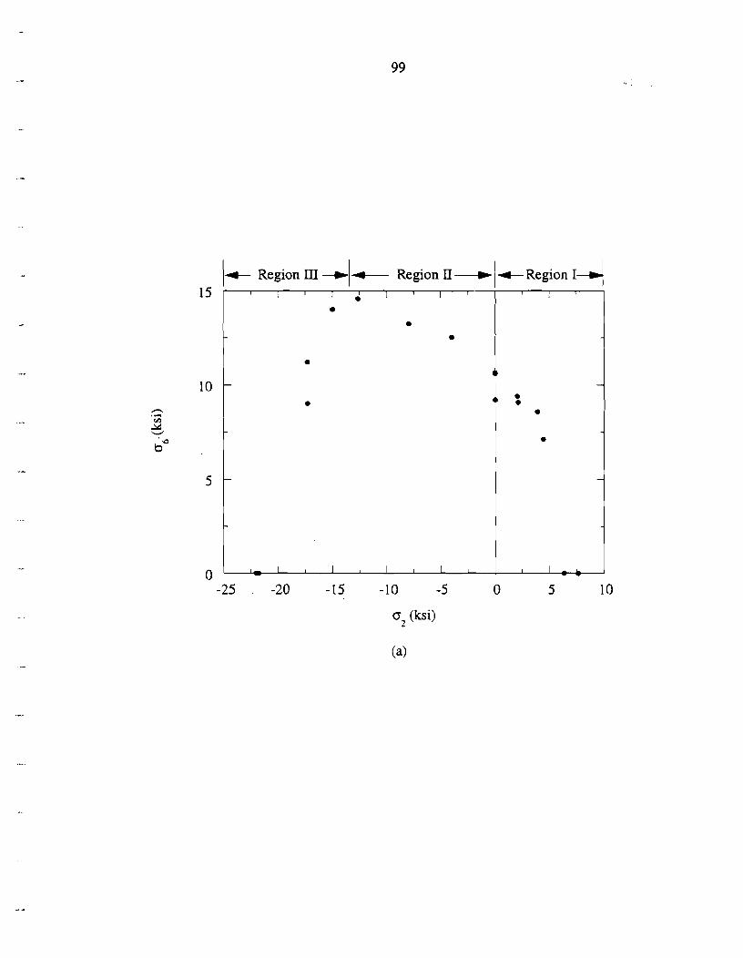
Ic Region III -1- Region 11 --t c ~ e ~ i o n 14
5 (ksi)


Fig. A.4 Failure envelope for a hoop-wound E-glass/epoxy composite; (a) Stress-based, and (b) Strain-based failure
~ e ~ i o n Region d 0.07 , I , I I I I , 11 I I
0.06
I - . - i. . -
a 1 m . 4 . . -
0.05 Region III -7' I
-0.06 -0.05 -0.04 -0.03 -0.02 -0.01 0 0.0 1
0.04 r-"
0.03
0.02
0.01
0
- -
- m
- - - - -
I A I I I 1 t I I I I


Fig. A.5 Fracture of a hoop-wound E-glasslepoxy composite subjected to transverse tension (a, = 6.40 ksi; a, = 0); (a) Overall fracture surface, and (b) Matrix fracture and fiber debonding

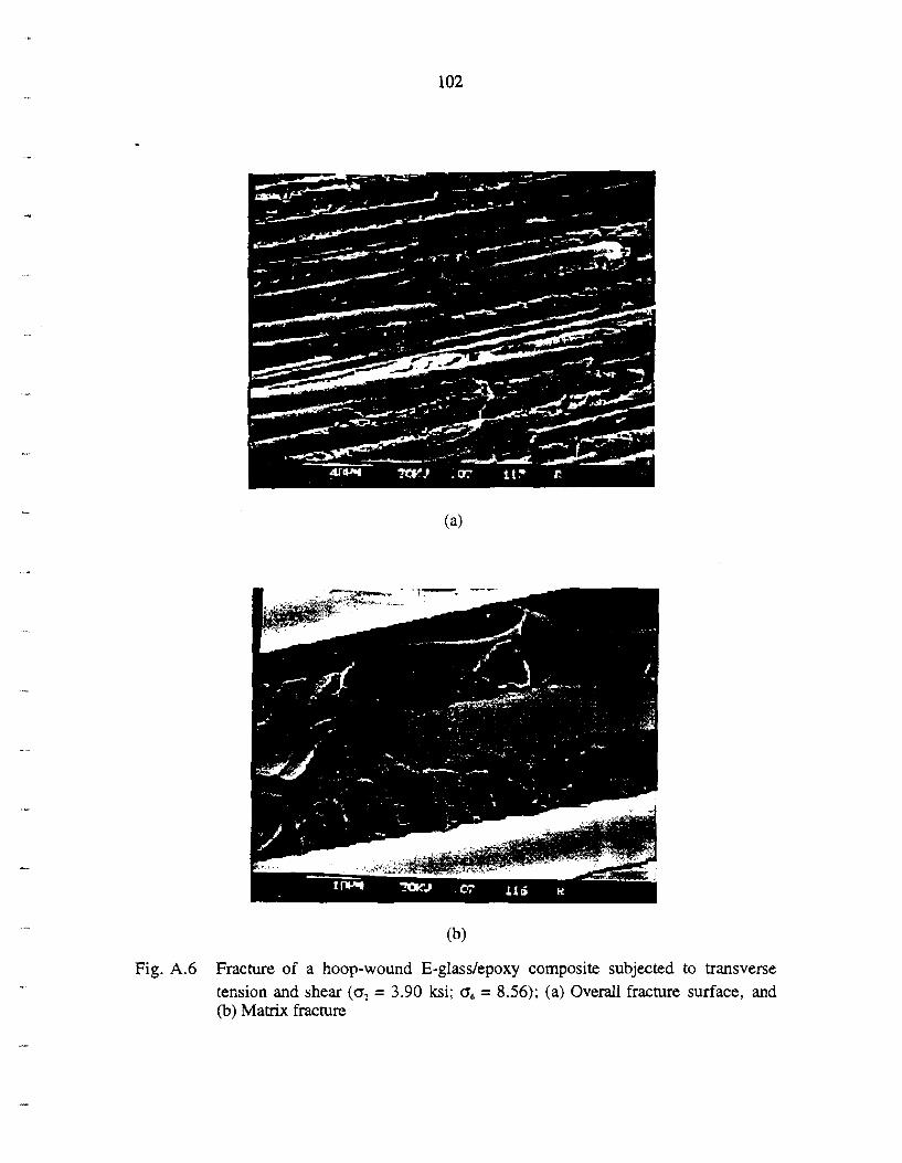
Fig. A.6 Fracture of a hoop-wound E-glass/epoxy composite subjected to transverse tension and shear (o? = 3.90 ksi; o, = 8.56); (a) Overall fracture surface, and (b) Matrix fracture


Fig. A.7 Fracture of a hoop-wound E-glass/epoxy composite subjected to pure shear (0, = '3 ksi; o6 = 10.59 ksi); (a) Overall fracture surface, and (b) Matrix fracture


Fig. A.8 Fracture of s hoop-wound E-glass/epoxy composite subjected to transverse compression and shear (oZ = -15.0 ksi; 0, = 14.01); (a) Overall fracture surface. and (b) Matrix fracrure and fiber debonding

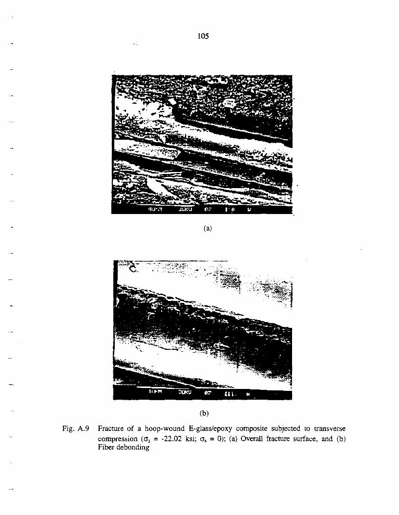
Fig. A.9 Fracture of a hoop-wound E-glass/epoxy composite subjected to transverse compression (a, = -22.02 ksi; a, = 0); (a) Overall fracture surface, and (b) Fiber debonding


o, (ksi)
15
10
h . - V1
5 0-
5
Fig. A. 10 Stress-based matrix-dominated failure criteria and experimental data for a hoop- wound E-glass/epoxy composite
0 -25 -20 -15 - 10 -5 0 5 10
I I I I
,
, / ' 'Y
-
I I t
O -
/ ' O
- ~ Experiment
- Eq. (A.2a) - Eq. (A.2c) 1
- Eq. (A.2d)


8 . Eq. (A.3a)
"- . . . Eq. (A.3b)
. . - . - . . - - Eq. (A.3c)
Fig. A. 11 Strain-based matrix-dominated failure criteria and experimental data for a hoop- wound E-glass/epoxy composite


End
Fig. B. 1 Unidirectional E-glasslepoxy specimen for a transverse tensile test at elevated temperature

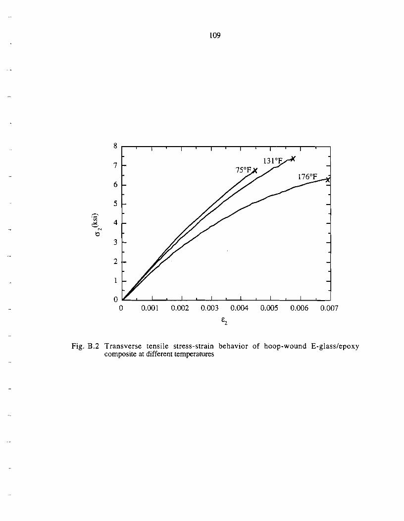
Fig. B.2 Transverse tensile stress-strain behavior of hoop-wound E-glass/epoxy composite at different temperatures

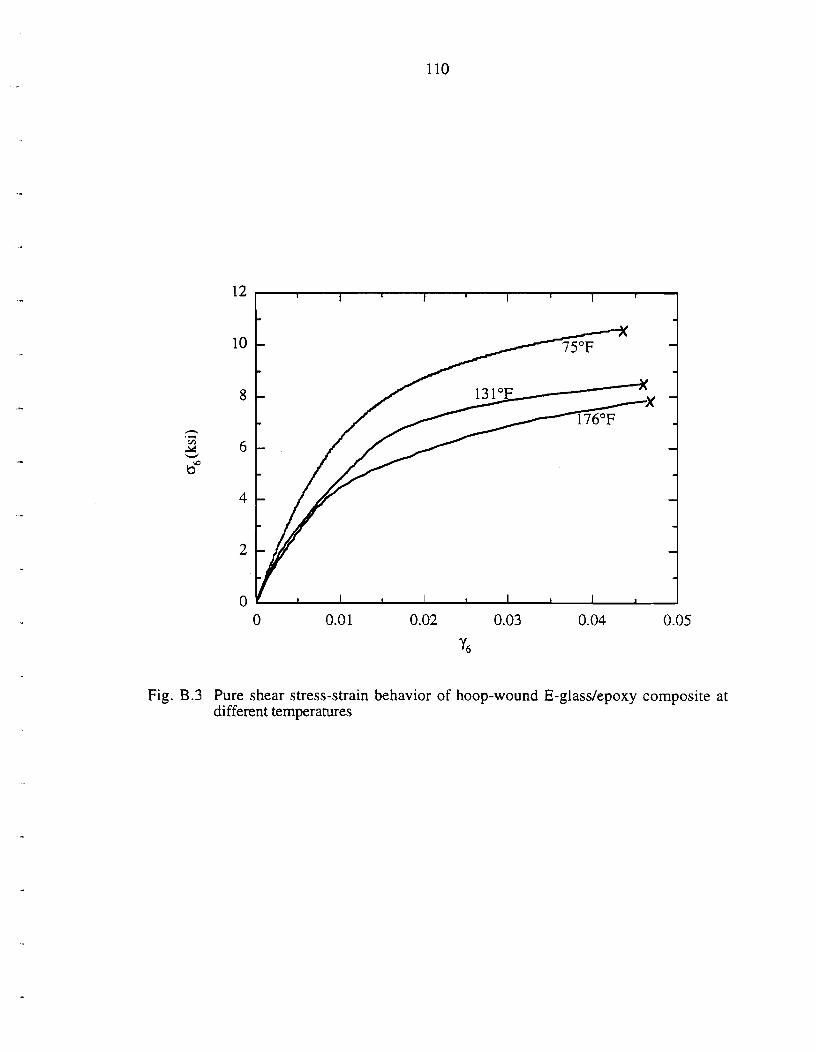
Fig. B.3 Pure shear stress-strain behavior of hoop-wound E-glasslepoxy composite at different temperatures


RVE
Fig.C. 1 (a) Composite ply cracking and a representationve unit cell
I I
Fig. C.l (b) Unit cell for homogenization theory and analysis

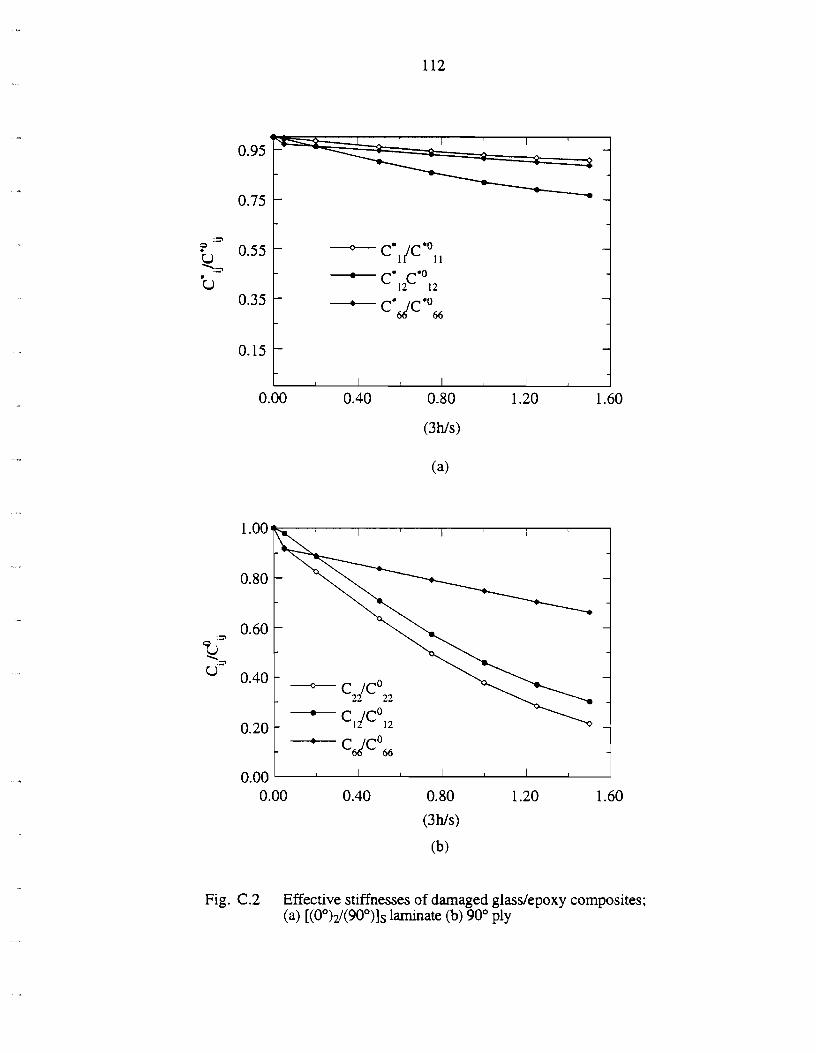
Fig. C.2 Effective stiffnesses of damaged glasslepoxy composites; (a) [(0°)2/(900)]s laminate (b) 90" ply


TABLES IN APPENDICES
Table A. 1 Mechanical ~ r o ~ e m e s of hoou-wound E-elass/e~oxv com~osites*t
s6666
X; (ksi)
X; (ksi)
X i (ksi)
X6 (ksi)
&:(+) &:(+) Ef (-1
2
Temperature
131°F
'Fiber volume fraction V ~ 0 . 5 7
?Glass transition temperature Tg = 22 1°F from DSC measurement


