longwall face supports in the german coal mining … · longwall face supports in the german coal...
TRANSCRIPT

LONGWALL FACE SUPPORTS IN THE GERMAN COAL MINING INDUSTRY
ALMANYA KÖMÜR MADENCİLİĞİNDE UZUN AYAK TAHKİMATI
H. LANGENBERG (*)
ABSTRACT
During the last decade face support technology developed at a breathtaking rate The varied geological and operational conditions during this rapid development have lead to a variety of designs and have provided a great experience to eperators and manufacturers.
Powered Supports today form an integral part of modern fully mechanised longwall systems.
The development of powered supports and of their latest types of chockshield and shield supports has expanded the scope of longwall mining to thin, extremely thick (more than 5 m thickness) and inclined seams For an optimum layout nf a powered support system compilation and evaluation of all parameters relevant to strata control is essential
ÖZET
Son on yıl içinde uzunayak tahkimat teknolojisi çok büyük bir gelişme göstermiştir. Bu hızlı gelişme sırasında değişik jeolojik ve işletme koşulları, farklı tasarımların yapılmasına neden olmuş ve işletmeci ile yapımcılara büyük deneyim kazandırmıştır.
Bugünkü yürüyen tahkimat, tam mekanize uzunayak sisteminin modern bir parçasıdır.
Yürüyen tahkimatın gelişmesi ve kalkan tipi tahkimatın en son tipleri; eğimli, ince ve çok kalın damarlarda (5 m'den fazla) uzunayak sisteminin uygulanmasını sağlamıştır. Tabaka kontrolü ile ilgili bütün parametrelerin değerlendirilmesi ve en uygun uzunayak sisteminin planlanması gerekmektedir.
(*) Dr. - Ing. Helmut Langenberg, Chief Mining Adviser, Gewerkschaft Eisenhütte Westtalsa GmbH, Lünen, FRG.
273

I. INTRODUCTION
Longwall face technology has rapidly developed over the last twenty years expressed in higher face outputs and higher efficiency on the one side and in more reliable and heavier face equipments on the other side. Average daily face production in the Federal Republic of Germany increased from 466 tons of saleable coal in 1965 to 1496 tons in 1983, average face output per manshift increased in the same period from 7,8 to 21,8 tons of saleable coal (1). The installed driving capacity for coal winning machines (ploughs and shearers) in some cases has gone up to 600 or even 1000 kW. For the face conveyors a trend towards more powerful rated drive units (300 kW and more) and heavier structures is continuing. In October 1983 1 % of all AFCs had line pans weighing between 200 and 300 kg, 89 % weighing between 300 and 400 kg and 10 % weighing bewteen 400 and 500 kg as compared to 35 % (200-300 kg), 64 % (300-400 kg) and 1 % (400-500 kg) in October 1975. Out of 222 faces in October, 4 with frame-type units, 7 with individual pop and timber supports giving the powered support faces a share of 98,3 % of face production.
2. DEVELOPMENT OF FACE SUPPORTS
Table 1 gives details of the number and daily saleable output of shearer and plough faces with shield and chockshield supports in the various ranges of seam thickness in October 1983 in the coal mining industry in the Federal Republic of Germany. The majority of the shearer faces equipped with shield supports (88 %) are in seams with an extracted thickness of more than 1.9 m, whereas the majority of the plough faces with shield supports {88 %) are in seams with an extracted thickness of more than 1.9 m, whereas the majority of the plough faces with shield supports (88 %) worked in seams of 1.9 m and less.
Roof support on the face has to secure the roof at any stage of face advance, to keep the working space open for coal getting and ventilation, to protect the miners in the face from roof falls and to form an anchorage for the forces required to advance the coal getting and conveying system of the face.
Longwall face supports developed from single props with roof bars to self-advancing supports (frame - and chock - type) and finally to shield supports with 2 or 4 props (Figure 1).
In the early seventies shield supports of the caliper type were first introduced in the German coal mining industry. Following their initial success these supports were brought into service on about 40 faces within a very short time.
The frequent occurence of geological faults and of zones of high strata pressure due to multiple seam extraction in the German coal mines requires high standards of mechanical and operational chracteristics of powered longwall face supports. Though chock-type and frame-type supports are still in use, shield and chockshield
274
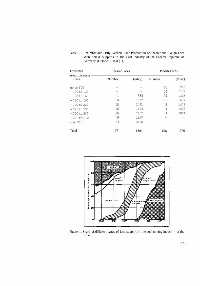
Table 1 — Number and Dafly Saleable Face Production of Shearer and Plough Face With Shield Supports in the Coal Industry of the Federal Republic of Germany (October 1983) (1).
Extracted Shearer Faces Plough Faces seam thickness
(cm) Number (t/day) Number (t/day)
up to 100 + 100 to 130 + 130 to 160 + 160 to 190 + 190 to 220
+ 220 to 250 + 250 to 280 + 280 to 310 over 310
— — 1 8 15 16 16 9 13
— —
533 1597 1491 1694
1682 2127 2410
10 34 29 22 8 4 1 -—
1228 1172
1315 1697 1478 1693
2001 — -
Total 78 1801 108 1376
Figure 1. Share of different types of face support in the coal mining industr < of the FRG.
275

Supports are generally accepted to-day as more appropriate to difficult mining conditions and 85 % of the output from longwall faces comes from faces with shield and chockshield supports.
In a caliper shield the roof canopy is connected with the caving shield by a pivot pin, the caving shield being connected to the base frame by another pin at its rear end (Figure 2). As the supporting props are arranged between the caving shield and the floor base the canopy pivot point follows an arc curve during hdyraulic adjustment of the props. Thus at convergence a relative movement occurs between the roof canopy and the floor base introducing very high and uncontrolled stresses in the structural components of the shield in case friction at roof or floor is high {steps in the roof or ft'"1-). Another common feature of the caliper shields is that the supporting prof forces are acting on the caving shield resulting in high bending forces and therefore heavy structures. The support resistance F A B of such designs depends on the positioning and inclination of the props with a lever ratio e/f of 0.75 or less (2).
OS 10 15 20 !5 30
«Im]
Figure 2. Schematic diagram, formula, characteristic curves and design features of caliper shield.
276

Considering the limitations of the caliper shield under difficult roof conditions and high strata pressure shields were developed with the props being arranged under the roof canopy. Four leg shields with lemniscatic linkage between the caving sh ield and the floor base were first introduced at Monopol Mine in 1974 (3).
The lemniscatic linkage is a dual-link mechanism with a pole point outside the structures resulting in a near straight vertical movement of the articulation between the roof canopy and the caving shield over the full range of vertical adjustment of the props, thus keeping the tip of the roof canopy at a near-constant distance to the coal front (Figure 3). Since in chockshield supports the roof canopy İs supported by two pairs of props the supports remain stable even if the caving line moves in front of the rear props particularly since the ring area of rear props can be pressurized inducinga high tip load of the roof canopy (Figure (4).
Figure 3. Schematic diagram, formula, characteristic curve and design features of chockshield with four props in parallel configuration.
277

Figure 4. Counter-pressurisation of rear and front props in a chockshield.
Two-leg-shields with lemniscatic linkage (Figure 5) can be regarded as a variant of the four-leg shields where the rear props are replaced by a stabilising cylinder between the caving shield and the roof canopy. The two-leg shields are shorter than the four-leg shields, but the position of the load center which depends on the magnitude and direction of the forces of the stabilising cylinder and the curve followed by the pole point must be carefully designed to avoid tilting of the support (Figure 6). Investigations (4) show that the load center is located close to the props linkage point to the canopy if the pole point is one the level of the roof canopy, it is located İn front of the props if the pole point lies below the canopy and located behind the props if the pole point lies above the canopy (Figure 7).
For utilisation of shield supports under changing operational conditions the subsequent development shows an increase of the range of vertical height adjustment and more compact designs.
The design features of supports with a wide range of vertical adjustment cover the introduction of multiple stage props and their inclination (Figure 8). A single telescopic prop of a given design (1800 kN) İn vertical position (Figure 8a) attains a ratio of vertical adjustment of about 1.7: 1, İn inclined position with an angle of 30° the ratio goes up to about 1.9 : 1 (Figure 8b). A double telescopic prop of the same load at 30° inclination attains a ratio of 2.6 : 1 (Figure 8c) and a triple telescopic prop a ratio of about 3 : 1 (Figure 8d). The majority of modern shield supports use double telescopic props at various inclinations. In chock shields with a wide range of adjustment the props are arranged in a V-type configuration {Figure 9). It is possible to shorten the canopy of such chock shields by arranging the props in an X-form (Figure 10) using either four or three props. Triple telescopic props (Figure 11) are primarily used to improve the characteristic curve of the supports as these at a desired ratio of extended height to closed height can have a position closer to vertical position (Figure 12).
278
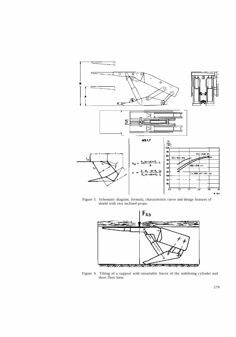
Figure 5. Schematic diagram, formula, characteristic curve and design features of shield with two inclined props.
Figure 6. Tilting of a support with unsuitable forces of the stabilising cylinder and short floor base.
279
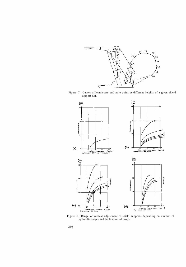
Figure 7. Curves of lemniscate and pole point at different heights of a given shield support (3).
Figure 8. Range of vertical adjustment of shield supports depending on number of hydraulic stages and inclination of props.
280

Figure 9. Schematic diagram, formula, characteristic curve and design features of chock shield with four props in V-type configuration.
281
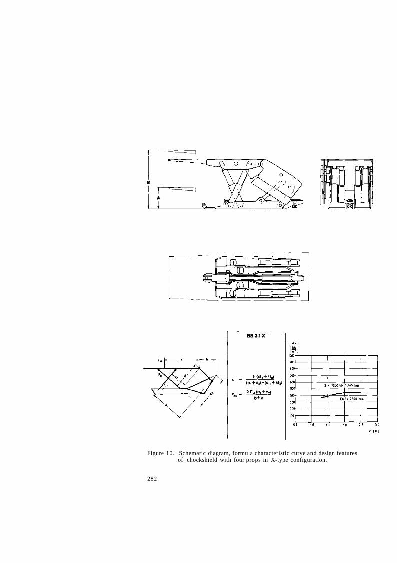
Figure 10. Schematic diagram, formula characteristic curve and design features of chockshield with four props in X-type configuration.
282
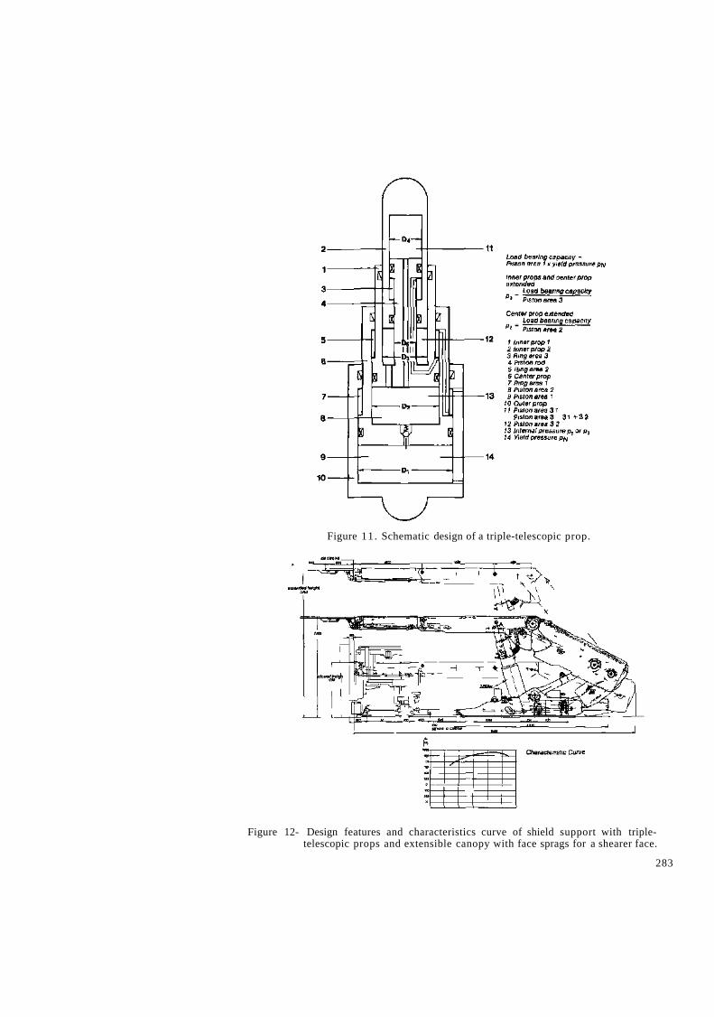
Figure 11 . Schematic design of a triple-telescopic prop.
Figure 12- Design features and characteristics curve of shield support with triple-telescopic props and extensible canopy with face sprags for a shearer face.
283

3. CURRENT FACE SUPPORTS
Since the shields and chock shields are relatively heavy and expensive recent developments tend to the design of lighter and cheaper types and to automatic support control. The trend goes to better utilisation of the supporting force inherent in the props and the minimisation of internal and external forces acting on the support structure. Internal, forces are lowest, when the props are vertical or perpendicular to roof and floor. This can be achieved by utilisation of double-or triple telescoping props. External forces can be limited by elastic or hydraulically adjustable link bars in the lemniscatic linkage (Figure 13), (5). The forces of the props can be better utilised when the difference between setting load and yield load is reduced to 10 to 20 % and with full-set controls able to build up the required setting loads in the props independent from the skill of operators (6). These
F A B : support resistance FH : supporting force parallel to stratification FL : link bar force
Figure 13. Pulling forces in rigid and hydraulic link bars in shield supports depending on shield height.
284
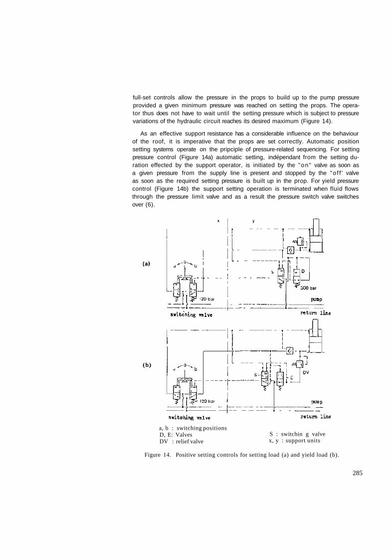
full-set controls allow the pressure in the props to build up to the pump pressure provided a given minimum pressure was reached on setting the props. The operator thus does not have to wait until the setting pressure which is subject to pressure variations of the hydraulic circuit reaches its desired maximum (Figure 14).
As an effective support resistance has a considerable influence on the behaviour of the roof, it is imperative that the props are set correctly. Automatic position setting systems operate on the pripciple of pressure-related sequencing. For setting pressure control (Figure 14a) automatic setting, indépendant from the setting duration effected by the support operator, is initiated by the "on" valve as soon as a given pressure from the supply line is present and stopped by the "o f f ' valve as soon as the required setting pressure is built up in the prop. For yield pressure control (Figure 14b) the support setting operation is terminated when fluid flows through the pressure limit valve and as a result the pressure switch valve switches over (6).
a, b : switching positions D, E: Valves DV : relief valve
S : switchin g valve x, y : support units
Figure 14. Positive setting controls for setting load (a) and yield load (b).
285
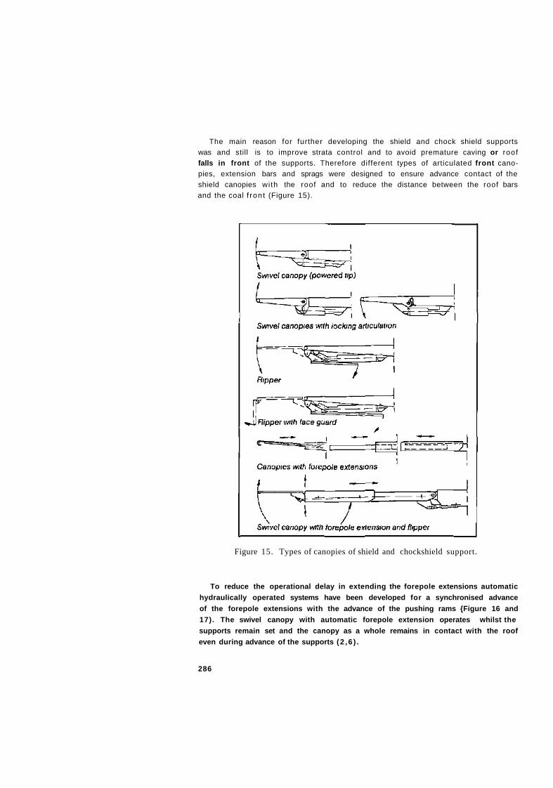
The main reason for further developing the shield and chock shield supports was and still is to improve strata control and to avoid premature caving or roof falls in front of the supports. Therefore different types of articulated front canopies, extension bars and sprags were designed to ensure advance contact of the shield canopies wi th the roof and to reduce the distance between the roof bars and the coal f ront (Figure 15).
Figure 15. Types of canopies of shield and chockshield support.
To reduce the operational delay in extending the forepole extensions automatic hydraulically operated systems have been developed for a synchronised advance of the forepole extensions with the advance of the pushing rams {Figure 16 and 17). The swivel canopy with automatic forepole extension operates whilst the supports remain set and the canopy as a whole remains in contact with the roof even during advance of the supports (2 ,6 ) .
286
za/ za/

center distance has been increased to 1.75 or even 2 m with a reduction of the specific support weight per m of face length (Figure 18). This, however, involves a totally different conveyor design resulting in a greater sideward displacement in S—curves (7).
Figure 18. Relation of specific support weight per m of face length with different ranges of vertical adjustment (v) and center distances (B) of support units.
During operation of supports in a longwall face setting pressure in the supply line drops depending on the flow, the hose diameter and the mode of supply line placement (straight or in loops). Measurements on face supply lines have revealed that supply volumes of 120 to 160 1/min are required in plough faces in thrn and medium seams and of 160 to 240 l/min in shearer faces in medium and thick seams The pressure drop in supply lines which between face entry and face end may be some 65 bars in setting pressures available for prop setting (8).
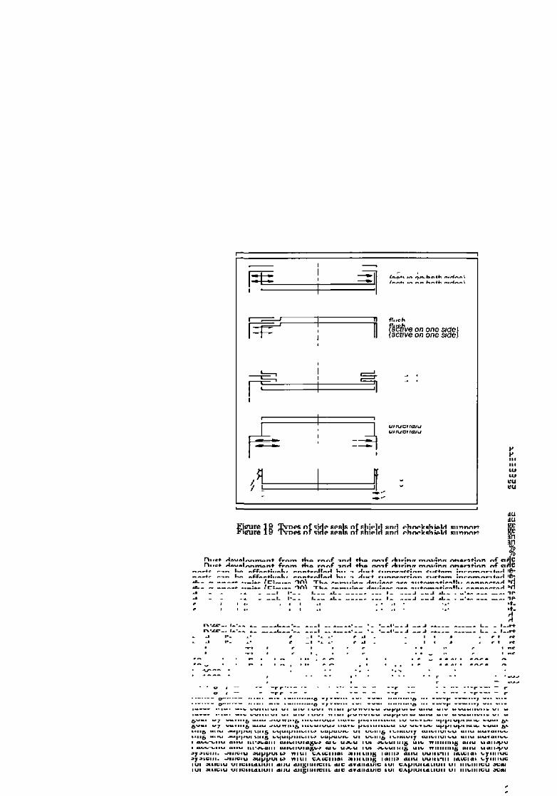
To reduce the development of airborne dust İn powered support faces the roof canopies and the caving shields are equipped with side seals, which close the gap between adjacent support units and prevent the debris lying on the canopies from falling into the working area (Figure 19). Tests have shown that the superimposed side seals with sharp-edged lateral plates offer the best results in dust protection, whereas the hinged types are the least effective.
288

1 : water supply line 2 : spray water valve 3 . switch-over valve 4 : spray nozzle fixation 5 - spray nozzle 6 . shut-off valve
A : prop lowering line B pushing ram extension line C ' prop setting line W : Water supply
Figure 20. Shield supports with build-in dust suppression system.
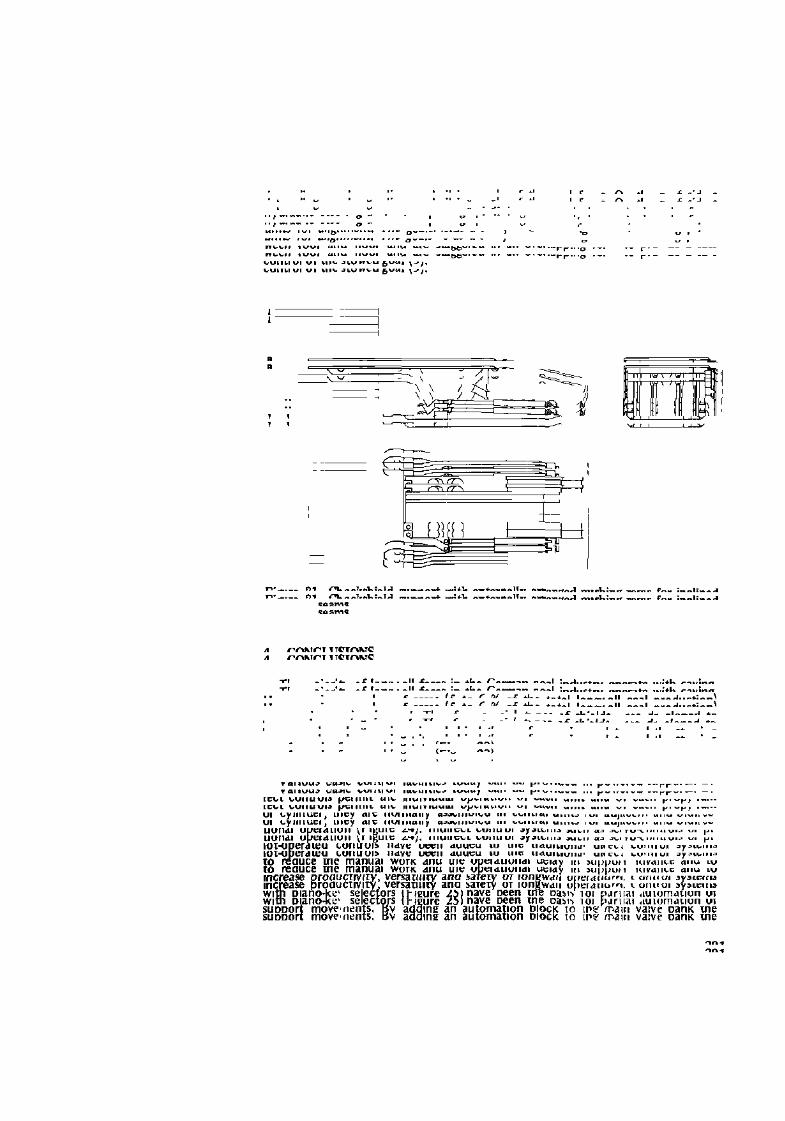
by the ploughing method up to a gradient of 60 gon (Figure 21). Frame-type supports assembled to a guide beam are successfully used in steep seams (80 to 90 gon) with coal getting by a shearer and gravity stowing (Figure 22). On the coal face side these supports are linked to articulated beams forming a chain-like guide for the shearer. A shifting unit located on one side of the frames is connected to this beam chain in a way permitting the frame to take angles ranging from 12 to 35°
290
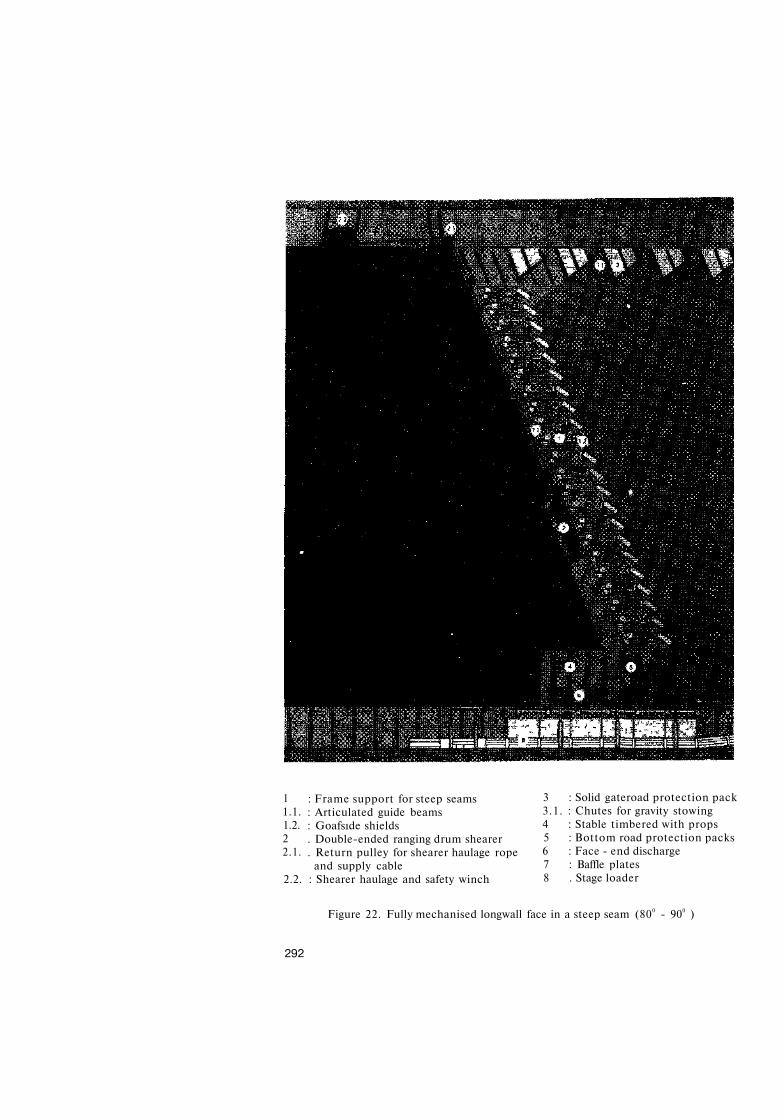
: Frame support for steep seams : Articulated guide beams : Goafsıde shields . Double-ended ranging drum shearer . Return pulley for shearer haulage rope
and supply cable 2.2. : Shearer haulage and safety winch
1 1.1. 1.2. 2 2.1.
3 : Solid gateroad protection pack 3.1. : Chutes for gravity stowing 4 : Stable timbered with props 5 : Bottom road protection packs 6 : Face - end discharge 7 : Baffle plates 8 . Stage loader
Figure 22. Fully mechanised longwall face in a steep seam (800 - 900 )
292
&
r"""" *«r. ST»™
'""Zi&T»^^ f"rm^
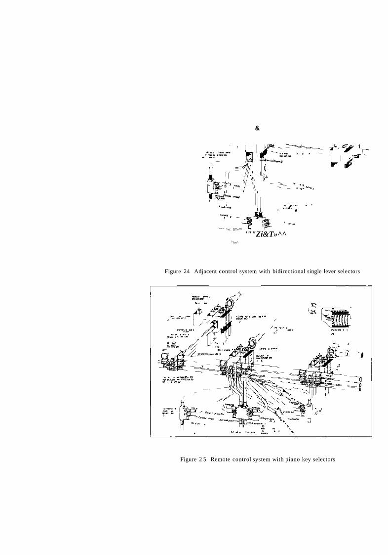
Figure 24 Adjacent control system with bidirectional single lever selectors
Figure 2 5 Remote control system with piano key selectors
•ı*r** T C
l y u i d u ı i v l u n u u i ımpuıae ic iedseu l y u i d u i i L L u i i u u i _ ımpuıae ıcıcdseu
L i i k t b i i L i i a i i u i i i n u a i \ t J i u t u i L I i t g u a i g e n u i g L i i k t b i i L i i a i i u i i i n u a i \ t J i u t u i L I i t g u a i g e n u i g
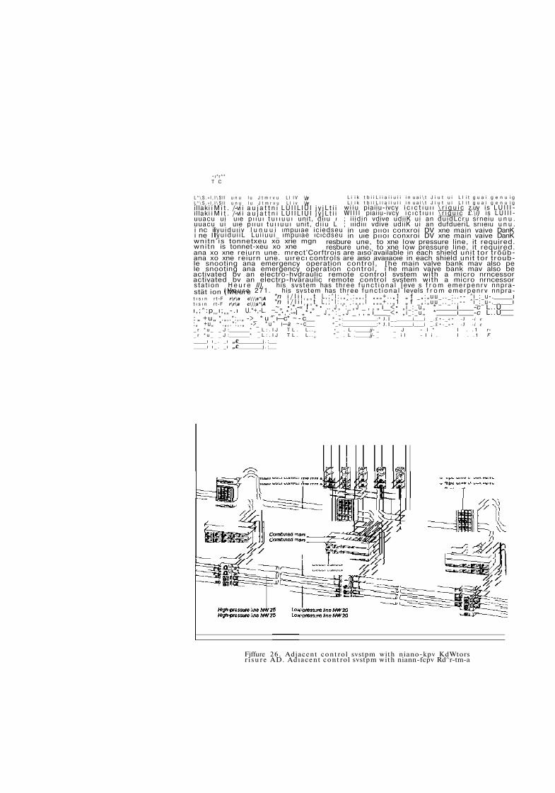
w i i u piai iu-ivcy i c ı c t ı u ı ı \ r i g u i c z.uy is L U I I I -W I I I I piai iu-ivcy i c ı c t ı u ı ı \ r i g u i c £.\i) i s L U I I I -; i i i d i n vdive udi iK u i an d u i d L c r u srneiu u n u . ; ı ı idiı ı vdive udi iK ui an dufdueriL srııeıu u n u .
in uıe pııoı conxroi DV xne main vaive DanK in uıe pııoı conxroi DV xne main vaive DanK
resbure une, to xne low pressure line, it required. resbure une, to xne low pressure line, it required.
L * \ S . » I , I \ S I I u n u l u J t m r v u L I I V \jy L * \ S . » I , I \ S I I u n u l u J t m r v u L I i v \jy i l laki i M i t . /-vi i a u j a t t n i L U I I L I U I j y j L t i i i l laki i M i t . /-vi i a u j a t t n i L U I I L I U I j y j L t i i uuacu u i uıe p ı ı u ı t u ı ı u u ı unit , d i ı u ı uuacu u i uıe p ı ı u ı t u ı ı u u ı unit , d i i u L i nc ii i ne I I w n i t n ' i s tonnetxeu xo xrie mgn w n i t n is tonnet-xeu xo xne ana xo xne reiurn une. mrect'Corftrois are aıso'available in each shield unit t o r trôûb-ana xo xne reiurn une. u ı recı controls are aıso avaııaoıe in each shield unit t o r trouble snooting ana emergency operation control, [he main valve bank mav also pe le snooting ana emergency operation control, i he main vajve bank mav also be activated bv an electro-hvdraulic remote control svstem with a micro nrncessor activated bv an electrp-hväraulic remote control svstem with a micro nrncessor s t a t i o n H e u r e II), his s v s t e m has t h r e e f u n c t i o n a l [eve s f r o m e m e r p e n r v nnpra-
( H e u r e 2 7 1 . his s v s t e m has t h r e e f u n c t i o n a l levels f r o m e m e r p e n r v nnpra-*n i / l i i r a n t L , ; ^ I : , „ ^ + : „ „ , I „ „ „ + . . „ 1 „ f _ „ : „ u u _ . . _ : . . - - ^ i _ : _ u - . ı *n i / l i i r a n t L , ; ^ I : , „ ^ + : „ „ , I „ „ „ + . . „ 1 „ f _ „ : „ u u _ . . _ : . . - - ^ i _ : _ u - . ı
_~„ •,*.-« I „*• .. J „ ^ : _ „ J _ , , „ i _<• „ i _ : _ u „ * i -c L..Ü _~„•,*.-«I „*• _ J „ ^ : _ „ J _ , , „ i _<• „ i _ : _ u „ * i -c L..Ü
* _ » : :* J . I _ _ i i _ . £ • - _ « • -J - i e * _ » : :* J . I _ _ i i _ . £ • - _ « • -J - i e •_ . L . jj- _ _ J - I * I . . 1 r-"_ . L . jj- _ _ i l - I i . I . . 1 F
stät ion (Meure t ı s ı n rt-F r\r\a c\\\s*\A t ı s ı n rt-F r\r\a c\\\s*\A
ı , ;^ :p n r ı ; n n -. ı U.*+,-L. : „ +u„ * . „ , . * : , . „ ->_ * u ^ ı—c* ~ - c : „ +u„ * . „ , . * : , . „ ->_ * u ^ ı—a ~ - c _ r * u _ _ J : * _ L : . I J T L . L . . U
_ r * u _ _ J : * _ L : . I J T L . L . . U
ı ı _ . _ ı „£ j . : ı ı _ . _ ı „£ j . :
Fjffure 2 6 . Adjacent contro l svstpm with niano-kpv KdWtors r i s u r e AD. Adıacent contro l svstpm with niann-fcpv Rd^r-tm-a

3H t +
! # t -t
f -+
+ -f
^ ' t- i
m m [ % ) n n
f 4
( # f -t
n n 1- 4 1- -+
1- 4
t Lawerprops 2 Advance support 3 Sel props 4 Rarse canopy 5 tower props and advance support
simultaneously 6 Cancel /unction adi-Bncepanljne"alL H
adjacent support 7 End of panlme advance S Advance panlme S Lower canopy
10 Support locked out 11 Clearance for shearer operation 12 Automation oft 13 LH support 14 LH group nght-lefl 15 LH group lefl-nghl 16 SiBrt individual sequence/batch control 17 R H support IB R H group leh-nght 19 R H group right-left 20 Start bankpush 21 Alarm signal
I Advance panlmeladvance shield II Raise canopy/lower canopy
III Retract side seals/expand side seals IV Lower/raise L H prop V Lower/raise H H prop
Figure 27. Micro processor unit of electro-hydraulic control system.
REFERENCES
1.
2.
KUNDLL, H., Die Strebtechnik im deutschen Steinkohlenbergbau im Jahre 1983. (Face technology in the German coal industry in 1983). Gluckauf 120, 1984), pp 669/85. Westfalia Lünen, Mine Roof Support Systems. German Mining 2/1984, p p . 63/72, 3/84, 140/52. MULLER, K.H., Verbesserung des Betriebsergebnisses bei gestörtem Baufeld durch Bock-schilddusbau (Improvement of operational results in geologically disturbed panels by using chockshield support), Gluckauf 112, 1976, pp. 107/11. RATZ, B.W., Die Ausbau stutz kraft der Schildbau formen und deren Übertragung ins Hangende (Support resistance of shield supports and its transmission to the roof). Gluckauf 114, 1978, pp. 9/12. RATZ, B.W., Weiterentwicklung des Schildausbaus in den 30erjahren. (Further development of shield supports m the Eighties). Glückauf 119, 1983, pp. 925/30. RATZ, B.W., Wege zum Verbessern der Hangendbeherrschung im Gewinnungsfeld. (Ways of improving on • face roof control) Gluckauf 120, 1984, pp. 128/132. LANGENBERG, H., Ouestions to paper on Mining methods for thin, medium and thick seams. Journal of Mines, Metals and Fuels, Vol. XXXII, No. 3, pp. 147/52 HERWIG, H., Planung des Strebausbaus aus gebirgsmechanischer Sicht (The planning of face supports in terms of rock mechanics) Glückauf 120, 1984,pp, 125/27. CABAL, V.L., Experience gained in integral mechanisation of vertical seams at Soton pit, Ilunosa, Spain. German Mining 4/1984, pp. 196/204.
296