lorawan specification 1r0
TRANSCRIPT

7/23/2019 LoRaWAN Specification 1R0
http://slidepdf.com/reader/full/lorawan-specification-1r0 1/82
©2015 LoRa™ Alliance Page 1 of 82 The authors reserve the right to changespecifications without notice.
1
LoRa Specification 2Copyright © 2015 LoRa Alliance, Inc. All rights reserved.3
4
NOTICE OF USE AND DISCLOSURE5
Copyright © LoRa Alliance, Inc. (2015). All Rights Reserved.67
The information within this document is the property of the LoRa Alliance (―The Alliance‖) and its use and8disclosure are subject to LoRa Alliance Corporate Bylaws, Intellectual Property Rights (IPR) Policy and9Membership Agreements.10
11Elements of LoRa Alliance specifications may be subject to third party intellectual property rights, including12without limitation, patent, copyright or trademark rights (such a third party may or may not be a member of LoRa13 Alliance). The Alliance is not responsible and shall not be held responsible in any manner for identifying or failing14to identify any or all such third party intellectual property rights.15
16This document and the information contained herein are provided on an ―AS IS‖ basis and THE ALLIANCE17DISCLAIMS ALL WARRANTIES EXPRESS OR IMPLIED, INCLUDING BUT NOTLIMITED TO (A) ANY18WARRANTY THAT THE USE OF THE INFORMATION HEREINWILL NOT INFRINGE ANY RIGHTS OF THIRD19PARTIES (INCLUDING WITHOUTLIMITATION ANY INTELLECTUAL PROPERTY RIGHTS INCLUDING20PATENT, COPYRIGHT OR TRADEMARK RIGHTS) OR (B) ANY IMPLIED WARRANTIES OF21MERCHANTABILITY, FITNESS FOR A PARTICULAR PURPOSE,TITLE OR NONINFRINGEMENT.22
23IN NO EVENT WILL THE ALLIANCE BE LIABLE FOR ANY LOSS OF PROFITS, LOSS OF BUSINESS, LOSS24OF USE OF DATA, INTERRUPTION OFBUSINESS, OR FOR ANY OTHER DIRECT, INDIRECT, SPECIAL OR25EXEMPLARY, INCIDENTIAL, PUNITIVE OR CONSEQUENTIAL DAMAGES OF ANY KIND, IN CONTRACT OR26IN TORT, IN CONNECTION WITH THIS DOCUMENT OR THE INFORMATION CONTAINED HEREIN, EVEN IF27 ADVISED OF THE POSSIBILITY OF SUCH LOSS OR DAMAGE.28
2930The above notice and this paragraph must be included on all copies of this document that are made.31
32LoRa Alliance, Inc.332400 Camino Ramon, Suite 37534San Ramon, CA 9458335Note: All Company, brand and product names may be trademarks that are the sole property of their respective36owners.37
3839404142
4344
45

7/23/2019 LoRaWAN Specification 1R0
http://slidepdf.com/reader/full/lorawan-specification-1r0 2/82
LoRaWAN Specification
©2015 LoRa™ Alliance Page 2 of 82 The authors reserve the right to changespecifications without notice.
1
2
LoRaWAN™ Specification3
4Authors:5N. Sornin (Semtech), M. Luis (Semtech), T. Eirich (IBM), T. Kramp (IBM),6O.Hersent (Actility)7
8Version: V1.09
Date: 2015 January10Status: Released 11
12131415
Important note: This is a candidate specification for the16LoRa™ Alliance protocol named LoRaWAN™.17
181920
7/23/2019 LoRaWAN Specification 1R0
http://slidepdf.com/reader/full/lorawan-specification-1r0 3/82
LoRaWAN Specification
©2015 LoRa™ Alliance Page 3 of 82 The authors reserve the right to changespecifications without notice.
Contents1
1 Introduction .................................................................................................................. 7 21.1 LoRaWAN Classes .................................................................................................. 7 31.2 Conventions ............................................................................................................. 8 4
2 Introduction on LoRaWAN options ............................................................................... 9 52.1 LoRaWAN Classes .................................................................................................. 9 62.2 Specification scope ................................................................................................ 10 7
Class A – All end-devices ................................................................................................... 11 83 Physical Message Formats ........................................................................................ 12 9
3.1 Uplink Messages .................................................................................................... 12 103.2 Downlink Messages ............................................................................................... 12 113.3 Receive Windows................................................................................................... 12 12
3.3.1 First receive window channel, data rate, and start ............................................ 13 133.3.2 Second receive window channel, data rate, and start ....................................... 13 143.3.3 Receive window duration .................................................................................. 13 153.3.4 Receiver activity during the receive windows .................................................... 13 163.3.5 Network sending a message to an end-device ................................................. 13 173.3.6 Important notice on receive windows ................................................................ 14 183.3.7 Receiving or transmitting other protocols .......................................................... 14 19
4 MAC Message Formats ............................................................................................. 15 204.1 MAC Layer (PHYPayload) ...................................................................................... 15 214.2 MAC Header (MHDR field) ..................................................................................... 15 22
4.2.1 Message type (MType bit field) ......................................................................... 16 234.2.2 Major version of data message (Major bit field) ................................................ 16 24
4.3 MAC Payload of Data Messages (MACPayload) .................................................... 17 254.3.1 Frame header (FHDR) ...................................................................................... 17 264.3.2 Port field (FPort) ............................................................................................... 20 274.3.3 MAC Frame Payload Encryption (FRMPayload) ............................................... 20 28
4.4 Message Integrity Code (MIC)................................................................................ 21 295 MAC Commands........................................................................................................ 22 30
5.1 Link Check commands (LinkCheckReq, LinkCheckAns) ........................................ 23 315.2 Link ADR commands (LinkADRReq, LinkADRAns) ................................................ 23 325.3 End-Device Transmit Duty Cycle (DutyCycleReq, DutyCycleAns) .......................... 25 335.4 Receive Windows Parameters (RXParamSetupReq, RXParamSetupAns) ............ 26 345.5 End-Device Status (DevStatusReq, DevStatusAns) ............................................... 27 355.6 Creation / Modification of a Channel (NewChannelReq, NewChannelAns) ............ 27 365.7 Setting delay between TX and RX (RXTimingSetupReq, RXTimingSetupAns) ...... 28 37
6 End-Device Activation ................................................................................................ 30 386.1 Data Stored in the End-device after Activation ....................................................... 30 39
6.1.1 End-device address (DevAddr) ......................................................................... 30 406.1.2 Application identifier (AppEUI) .......................................................................... 30 416.1.3 Network session key (NwkSKey) ...................................................................... 30 426.1.4 Application session key (AppSKey) .................................................................. 30 43
6.2 Over-the-Air Activation ........................................................................................... 30 446.2.1 End-device identifier (DevEUI) ......................................................................... 31 456.2.2 Application key (AppKey) ................................................................................. 31 466.2.3 Join procedure.................................................................................................. 31 47
6.2.4 Join-request message ...................................................................................... 31 48 6.2.5 Join-accept message........................................................................................ 32 496.3 Activation by Personalization ................................................................................. 33 50

7/23/2019 LoRaWAN Specification 1R0
http://slidepdf.com/reader/full/lorawan-specification-1r0 4/82
LoRaWAN Specification
©2015 LoRa™ Alliance Page 4 of 82 The authors reserve the right to changespecifications without notice.
7 Physical Layer ........................................................................................................... 34 17.1 EU 863-870MHz ISM Band .................................................................................... 34 2
7.1.1 EU863-870 Preamble Format ........................................................................... 34 3
7.1.2 EU863-870 ISM Band channel frequencies ...................................................... 34 47.1.3 EU863-870 Data Rate and End-point Output Power encoding ......................... 35 57.1.4 EU863-870 JoinAccept CFList .......................................................................... 35 67.1.5 EU863-870 LinkAdrReq command ................................................................... 36 77.1.6 EU863-870 Maximum payload size .................................................................. 36 87.1.7 EU863-870 Receive windows ........................................................................... 37 97.1.8 EU863-870 Default Settings ............................................................................. 37 10
7.2 US 902-928MHz ISM Band .................................................................................... 39 117.2.1 US902-928 Preamble Format ........................................................................... 39 127.2.2 US902-928 Channel Frequencies .................................................................... 39 137.2.3 US902-928 Data Rate and End-point Output Power encoding ......................... 39 147.2.4 US902-928 JoinResp CFList ............................................................................ 40 157.2.5 US902-928 LinkAdrReq command ................................................................... 40 167.2.6 US902-928 Maximum payload size .................................................................. 41 177.2.7 US902-928 Receive windows ........................................................................... 42 187.2.8 US902-928 Default Settings ............................................................................. 42 19
7.3 China 779-787MHz ISM Band ................................................................................ 43 207.3.1 CN779-787 Preamble Format ........................................................................... 43 217.3.2 CN779-787 ISM Band channel frequencies ...................................................... 43 227.3.3 CN779-787 Data Rate and End-point Output Power encoding ........................ 44 237.3.4 CN779-787 JoinAccept CFList ........................................................................ 44 247.3.5 CN779-787 LinkAdrReq command .................................................................. 45 257.3.6 CN779-787 Maximum payload size ................................................................. 45 26
7.3.7 CN779-787 Receive windows ........................................................................... 46 27 7.3.8 CN779-787 Default Settings ............................................................................ 46 287.4 EU 433MHz ISM Band ........................................................................................... 47 29
7.4.1 EU433 Preamble Format .................................................................................. 47 307.4.2 EU433 ISM Band channel frequencies ............................................................. 47 317.4.3 EU433 Data Rate and End-point Output Power encoding ................................ 48 327.4.4 EU433 JoinAccept CFList ................................................................................. 48 337.4.5 EU433 LinkAdrReq command .......................................................................... 49 347.4.6 EU433 Maximum payload size ......................................................................... 49 357.4.7 EU433 Receive windows .................................................................................. 50 367.4.8 EU433 Default Settings .................................................................................... 50 37
Class B – Beacon ............................................................................................................... 51 38
8 Introduction to Class B ............................................................................................... 52 399 Principle of synchronous network initiated downlink (Class-B option) ......................... 53 4010 Uplink frame in Class B mode .................................................................................... 55 4111 Downlink Ping frame format (Class B option) ............................................................. 56 42
11.1 Physical frame format ............................................................................................ 56 4311.2 Unicast & Multicast MAC messages ....................................................................... 56 44
11.2.1 Unicast MAC message format .......................................................................... 56 4511.2.2 Multicast MAC message format ........................................................................ 56 46
12 Beacon acquisition and tracking ................................................................................. 57 4712.1 Minimal beacon-less operation time ....................................................................... 57 4812.2 Extension of beacon-less operation upon reception ............................................... 57 4912.3 Minimizing timing drift ............................................................................................. 57 50
13 Class B Downlink slot timing ...................................................................................... 58 5113.1 Definitions .............................................................................................................. 58 5213.2 Slot randomization ................................................................................................. 59 53

7/23/2019 LoRaWAN Specification 1R0
http://slidepdf.com/reader/full/lorawan-specification-1r0 5/82
LoRaWAN Specification
©2015 LoRa™ Alliance Page 5 of 82 The authors reserve the right to changespecifications without notice.
14 Class B MAC commands ........................................................................................... 60 114.1 PingSlotInfoReq ..................................................................................................... 60 214.2 BeaconFreqReq ..................................................................................................... 61 3
14.3 PingSlotChannelReq .............................................................................................. 61 414.4 BeaconTimingReq .................................................................................................. 62 514.5 BeaconTimingAns .................................................................................................. 63 6
15 Beaconing (Class B option) ........................................................................................ 64 715.1 Beacon physical layer ............................................................................................ 64 8
15.1.1 EU 863-870MHz ISM Band .............................................................................. 64 915.1.2 US 902-928MHz ISM Band .............................................................................. 64 10
15.2 Beacon frame content ............................................................................................ 65 1115.3 Beacon GwSpecific field format .............................................................................. 66 12
15.3.1 Gateway GPS coordinate:InfoDesc = 0, 1 or 2 ................................................. 67 1315.4 Beaconing precise timing ....................................................................................... 67 1415.5 Network downlink route update requirements ......................................................... 67 15
16 Class B unicast & multicast downlink channel frequencies ......................................... 69 1616.1 EU 863-870MHz ISM Band .................................................................................... 69 1716.2 US 902-928MHz ISM Band .................................................................................... 69 18
Class C – Continuously listening ......................................................................................... 70 1917 Class C: Continuously listening end-device................................................................ 71 20
17.1 Second receive window duration for Class C ......................................................... 71 2117.2 Class C Multicast downlinks ................................................................................... 71 22
Support information ............................................................................................................. 72 2318 Examples and Application Information ....................................................................... 73 24
18.1 Uplink Timing Diagram for Confirmed Data Messages ........................................... 73 2518.2 The third ACK frame in this example also carries an application payload. A26
downlink frame can carry any combination of ACK, MAC control commands27 and payload. Downlink Diagram for Confirmed Data Messages ............................. 73 2818.3 Downlink Timing for Frame-Pending Messages ..................................................... 74 2918.4 Data-Rate Adaptation during Message Retransmissions........................................ 76 30
19 Recommendation on contract to be provided to the network server by the end-31device provider at the time of provisioning .......................................................................... 77 3220 Recommendation on finding the locally used channels .............................................. 78 3321 Revisions ................................................................................................................... 79 34
21.1 Revision 1.0 ........................................................................................................... 79 3522 Glossary .................................................................................................................... 80 3623 Bibliography ............................................................................................................... 81 37
23.1 References............................................................................................................. 81 38
24 NOTICE OF USE AND DISCLOSURE ....................................................................... 82 3940
Tables41
Table 1: MAC message types ............................................................................................. 16 42Table 2: Major list ................................................................................................................ 16 43Table 3: FPort list ................................................................................................................ 20 44Table 4: MAC commands .................................................................................................... 22 45Table 5: Channel state table ............................................................................................... 24 46Table 6: LinkADRAns status bits signification ..................................................................... 25 47
Table 7: RX2SetupAns status bits signification ................................................................... 26 48 Table 8: Battery level decoding ........................................................................................... 27 49Table 9: NewChannelAns status bits signification ............................................................... 28 50

7/23/2019 LoRaWAN Specification 1R0
http://slidepdf.com/reader/full/lorawan-specification-1r0 6/82
LoRaWAN Specification
©2015 LoRa™ Alliance Page 6 of 82 The authors reserve the right to changespecifications without notice.
Table 10: Del mapping table ............................................................................................... 29 1Table 11: EU863-870 synch words ..................................................................................... 34 2Table 12: EU863-870 default channels ............................................................................... 34 3
Table 13: EU863-870 JoinReq Channel List ....................................................................... 35 4Table 14: Data rate and TX power table .............................................................................. 35 5Table 15: ChMaskCntl value table....................................................................................... 36 6Table 16: EU863-870 maximum payload size ..................................................................... 37 7Table 17 : EU863-870 maximum payload size (not repeater compatible) ............................ 37 8Table 18: Data rate and TX power table (Rem: DR4 is identical to DR12, DR8..13 must be9implemented in end-devices and are reserved for future applications) ................................ 40 10Table 19: ChMaskCntl value table....................................................................................... 40 11Table 20: US902-928 maximum payload size (repeater compatible) ................................... 41 12Table 21 : US902-928 maximum payload size (not repeater compatible) ............................ 41 13Table 22: Data rate mapping ............................................................................................... 42 14Table 23: CN779-787 synch words .................................................................................... 43 15Table 24: CN780 JoinReq Channel List .............................................................................. 43 16Table 25: Data rate and TX power table .............................................................................. 44 17Table 26: ChMaskCntl value table....................................................................................... 45 18Table 27: CN780 maximum payload size ............................................................................ 45 19Table 28 : CN780 maximum payload size (not repeater compatible) ................................... 46 20Table 29: EU433 synch words ............................................................................................ 47 21Table 30: EU433 JoinReq Channel List .............................................................................. 47 22Table 31: Data rate and TX power table .............................................................................. 48 23Table 32: ChMaskCntl value table....................................................................................... 49 24Table 33: EU433 maximum payload size ............................................................................ 49 25Table 34 : EU433 maximum payload size (not repeater compatible) ................................... 50 26
Table 35: Beacon timing ..................................................................................................... 58 2728
Figures29
Figure 1: LoRaWAN Classes ................................................................................................ 9 30Figure 2: Uplink PHY structure ............................................................................................ 12 31Figure 3: Downlink PHY structure ....................................................................................... 12 32Figure 4: End-device receive slot timing. ............................................................................. 13 33Figure 5: Radio PHY structure (CRC* is only available on uplink messages) ...................... 15 34Figure 6: PHY payload structure ......................................................................................... 15 35
Figure 7: MAC payload structure ......................................................................................... 15 36Figure 8: Frame header structure ........................................................................................ 15 37Figure 9: LoRa message format elements ........................................................................... 15 38Figure 10: US902-928 channel frequencies ........................................................................ 39 39Figure 11: Beacon reception slot and ping slots .................................................................. 54 40Figure 12 : beacon-less temporary operation ...................................................................... 57 41Figure 13: Beacon timing .................................................................................................... 58 42Figure 14: Class C end-device receive slot timing. .............................................................. 71 43Figure 15: Uplink timing diagram for confirmed data messages .......................................... 73 44Figure 16: Downlink timing diagram for confirmed data messages ...................................... 74 45Figure 17: Downlink timing diagram for frame-pending messages, example 1 .................... 75 46Figure 18: Downlink timing diagram for frame-pending messages, example 2 .................... 75 47
Figure 19: Downlink timing diagram for frame-pending messages, example 3 .................... 75 4849
7/23/2019 LoRaWAN Specification 1R0
http://slidepdf.com/reader/full/lorawan-specification-1r0 7/82
LoRaWAN Specification
©2015 LoRa™ Alliance Page 7 of 82 The authors reserve the right to changespecifications without notice.
1 Introduction1
This document describes the LoRaWAN™ network protocol which is optimized for battery-2powered end-devices that may be either mobile or mounted at a fixed location.3
LoRaWAN networks typically are laid out in a star-of-stars topology in which gateways1 4relay messages between end-devices2 and a central network server at the backend.5Gateways are connected to the network server via standard IP connections while end-6devices use single-hop LoRa™ or FSK communication to one or many gateways.3 All7communication is generally bi-directional, although uplink communication from an end-8device to the network server is expected to be the predominant traffic.9
Communication between end-devices and gateways is spread out on different frequency 10channels and data rates. The selection of the data rate is a trade-off between11communication range and message duration, communications with different data rates do12
not interfere with each other. LoRa data rates range from 0.3 kbps to 50 kbps. To maximize13 both battery life of the end-devices and overall network capacity, the LoRa network14infrastructure can manage the data rate and RF output for each end-device individually by15means of an adaptive data rate (ADR) scheme.16
End-devices may transmit on any channel available at any time, using any available data17rate, as long as the following rules are respected:18
The end-device changes channel in a pseudo-random fashion for every19transmission. The resulting frequency diversity makes the system more robust to20interferences.21
The end-device respects the maximum transmit duty cycle relative to the sub-band22used and local regulations.23
The end-device respects the maximum transmit duration (or dwell time) relative to24the sub-band used and local regulations.25
Note: Maximum transmit duty-cycle and dwell time per sub-band are26region specific and are defined in the Chapter 6. 27
1.1 LoRaWAN Classes28
All LoRaWAN devices implement at least the Class A functionality as described in this29document. In addition they may implement options named Class B, Class C as also30described in this document or others to be defined. In all cases, they must remain31
compatible with Class A.32
1 Gateways are also known as concentrators or base stations.
2 End-devices are also known as motes.
3
Support for intermediate elements – repeaters – is not described in the document, however payloadrestrictions for encapsulation overhead are included in this specification. A repeater is defined asusing LoRaWAN as its backhaul mechanism.
7/23/2019 LoRaWAN Specification 1R0
http://slidepdf.com/reader/full/lorawan-specification-1r0 8/82
LoRaWAN Specification
©2015 LoRa™ Alliance Page 8 of 82 The authors reserve the right to changespecifications without notice.
1.2 Conventions1
MAC commands are written LinkCheckReq , bits and bit fields are written FRMPayload,2constants are written RECEIVE_DELAY1, variables are written N .3
In this document,4
The octet order for all multi-octet fields is little endian and5
EUI are 64 bits integers and are transmitted as little endian.6

7/23/2019 LoRaWAN Specification 1R0
http://slidepdf.com/reader/full/lorawan-specification-1r0 9/82
LoRaWAN Specification
©2015 LoRa™ Alliance Page 9 of 82 The authors reserve the right to changespecifications without notice.
2 Introduction on LoRaWAN options1
LoRa™ is a wireless modulation for long-range low-power low-data-rate applications2developed by Semtech. Devices implementing more than Class A are generally named3―higher Class end-devices‖ in this document.4
2.1 LoRaWAN Classes5
A LoRa network distinguishes between a basic LoRaWAN (named Class A) and optional6features (Class B, Class C …): 7
Application
LoRa MAC
LoRa Modulation
EU
868 EU433
US
915 AS430
…
Class B(beacon)
Class C(Continuous)
Application
MAC
MAC options
Modulation
Regional ISM band
Class A(baseline)
8Figure 1: LoRaWAN Classes9
Bi-directional end-devices (Class A): End-devices of Class A allow for bi-10directional communications whereby each end-device‘s uplink transmission is11followed by two short downlink receive windows. The transmission slot scheduled by12the end-device is based on its own communication needs with a small variation13based on a random time basis (ALOHA-type of protocol). This Class A operation is14the lowest power end-device system for applications that only require downlink15communication from the server shortly after the end-device has sent an uplink16transmission. Downlink communications from the server at any other time will have to17wait until the next scheduled uplink.18
Bi-directional end-devices with scheduled receive slots (Class B): End-devices19of Class B allow for more receive slots. In addition to the Class A random receive20windows, Class B devices open extra receive windows at scheduled times. In order21for the End-device to open it receive window at the scheduled time it receives a time22synchronized Beacon from the gateway. This allows the server to know when the23end-device is listening.24
Bi-directional end-devices with maximal receive slots (Class C): End-devices of25
Class C have nearly continuously open receive windows, only closed when26 transmitting. Class C end-device will use more power to operate than Class A or27Class B but they offer the lowest latency for server to end-device communication.28
7/23/2019 LoRaWAN Specification 1R0
http://slidepdf.com/reader/full/lorawan-specification-1r0 10/82
LoRaWAN Specification
©2015 LoRa™ Alliance Page 10 of 82 The authors reserve the right to changespecifications without notice.
2.2 Specification scope1
This LoRaWAN specification describes the additional functions differentiating an end-device2higher Class from one of Class A. A higher Class end-device shall also implement all the3functionality described in the LoRaWAN Class A specification.4
NOTE: Physical message format, MAC message format, and other5parts of this specification that are common to both end-devices of6Class A and higher Classes are described only in the LoRaWAN7Class A specification to avoid redundancy.8
7/23/2019 LoRaWAN Specification 1R0
http://slidepdf.com/reader/full/lorawan-specification-1r0 11/82
LoRaWAN Specification
©2015 LoRa™ Alliance Page 11 of 82 The authors reserve the right to changespecifications without notice.
CLASS A – ALL END-DEVICES 1
All LoRaWAN end-devices must implement Class A features.2
7/23/2019 LoRaWAN Specification 1R0
http://slidepdf.com/reader/full/lorawan-specification-1r0 12/82
LoRaWAN Specification
©2015 LoRa™ Alliance Page 12 of 82 The authors reserve the right to changespecifications without notice.
3 Physical Message Formats1
The LoRa terminology distinguishes between uplink and downlink messages.2
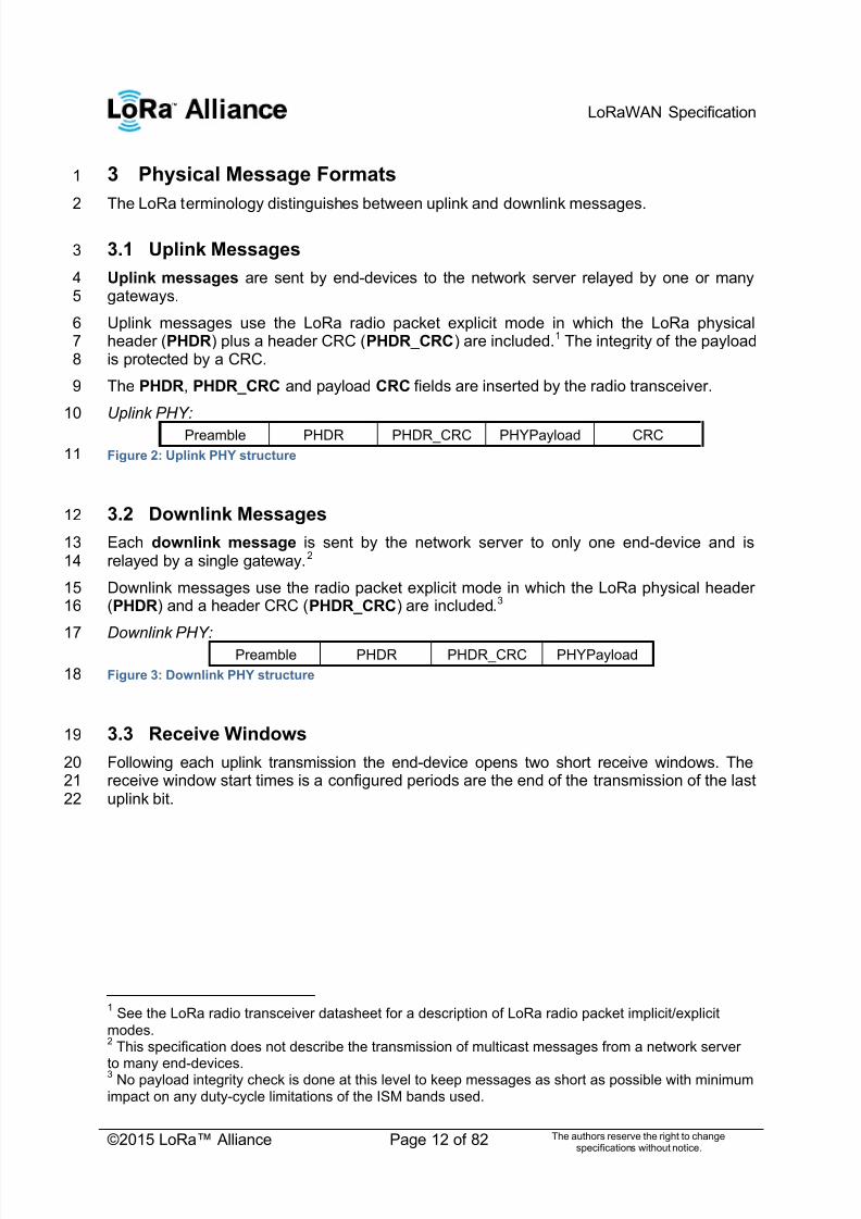
3.1 Uplink Messages3
Uplink messages are sent by end-devices to the network server relayed by one or many4gateways.5
Uplink messages use the LoRa radio packet explicit mode in which the LoRa physical6header (PHDR) plus a header CRC (PHDR_CRC) are included.1 The integrity of the payload7is protected by a CRC.8
The PHDR, PHDR_CRC and payload CRC fields are inserted by the radio transceiver.9
Uplink PHY:10
Preamble PHDR PHDR_CRC PHYPayload CRC
Figure 2: Uplink PHY structure11
3.2 Downlink Messages12
Each downlink message is sent by the network server to only one end-device and is13relayed by a single gateway.2 14
Downlink messages use the radio packet explicit mode in which the LoRa physical header15(PHDR) and a header CRC (PHDR_CRC) are included.3 16
Downlink PHY:17
Preamble PHDR PHDR_CRC PHYPayload
Figure 3: Downlink PHY structure18
3.3 Receive Windows19
Following each uplink transmission the end-device opens two short receive windows. The20receive window start times is a configured periods are the end of the transmission of the last21uplink bit.22
1 See the LoRa radio transceiver datasheet for a description of LoRa radio packet implicit/explicit
modes. 2 This specification does not describe the transmission of multicast messages from a network server
to many end-devices. 3 No payload integrity check is done at this level to keep messages as short as possible with minimum
impact on any duty-cycle limitations of the ISM bands used.

7/23/2019 LoRaWAN Specification 1R0
http://slidepdf.com/reader/full/lorawan-specification-1r0 13/82
LoRaWAN Specification
©2015 LoRa™ Alliance Page 13 of 82 The authors reserve the right to changespecifications without notice.
1Figure 4: End-device receive slot timing.2
3.3.1 First receive window channel, data rate, and start3
The first receive window RX1 uses the same frequency channel as the uplink and a data4rate that is a function of the data rate used for the uplink. RX1 opens RECEIVE_DELAY1 1 5seconds (+/- 20 microseconds) after the end of the uplink modulation. The relationship6between uplink and RX1 slot downlink data rate is region specific and detailed in the Section77. By default the first receive window datarate is identical to the datarate of the last uplink.8
3.3.2 Second receive window channel, data rate, and start9
The second receive window RX2 uses a fixed configurable frequency and data rate and10opens RECEIVE_DELAY21 seconds (+/- 20 microseconds) after the end of the uplink11modulation. The frequency and data rate used can be modified through MAC commands12(see Section 5).The default frequency and data rate to use are region specific and detailed13in the Section 7 .14
3.3.3 Receive window duration15
The length of a receive window must be at least the time required by the end-device ‘s radio16transceiver to effectively detect a downlink preamble.17
3.3.4 Receiver activity during the receive windows18
If a preamble is detected during one of the receive windows, the radio receiver stays active19until the downlink frame is demodulated. If a frame was detected and subsequently20
demodulated during the first receive window and the frame was intended for this end-device21 after address and MIC (message integrity code) checks, the end-device does not open the22second receive window.23
3.3.5 Network sending a message to an end-device24
If the network intends to transmit a downlink to an end-device, it will always initiate the25transmission precisely at the beginning of one of those two receive windows.26
1 RECEIVE_DELAY1 and RECEIVE_DELAY2 are described in Chapter 6.

7/23/2019 LoRaWAN Specification 1R0
http://slidepdf.com/reader/full/lorawan-specification-1r0 14/82
LoRaWAN Specification
©2015 LoRa™ Alliance Page 14 of 82 The authors reserve the right to changespecifications without notice.
3.3.6 Important notice on receive windows1 An end-device shall not transmit another uplink message before it either has received a2downlink message in the first or second receive window of the previous transmission, or the3
second receive window of the previous transmission is expired.4
3.3.7 Receiving or transmitting other protocols5
The node may listen or transmit other protocols or do any transactions between the6LoRaWAN transmission and reception windows, as long as the end-device remains7compatible with the local regulation and compliant with the LoRaWAN specification.8

7/23/2019 LoRaWAN Specification 1R0
http://slidepdf.com/reader/full/lorawan-specification-1r0 15/82
LoRaWAN Specification
©2015 LoRa™ Alliance Page 15 of 82 The authors reserve the right to changespecifications without notice.
4 MAC Message Formats1
All LoRa uplink and downlink messages carry a PHY payload (Payload) starting with a2single-octet MAC header (MHDR), followed by a MAC payload (MACPayload)1, and ending3with a 4-octet message integrity code (MIC).4
5
Radio PHY layer:6
Preamble PHDR PHDR_CRC PHYPayload CRC*
Figure 5: Radio PHY structure (CRC* is only available on uplink messages)7
PHYPayload:8
MHDR MACPayload MIC
Figure 6: PHY payload structure9
MACPayload:10
FHDR FPort FRMPayload
Figure 7: MAC payload structure11
FHDR:12
DevAddr FCtrl FCnt FOpts
Figure 8: Frame header structure13
Figure 9: LoRa message format elements14
4.1 MAC Layer (PHYPayload)15
16Size (bytes) 1 1..M 4
PHYPayload MHDR MACPayload MIC
17
The maximum length (M ) of the MACPayload field is region specific and is specified in18Chapter 6. 19
4.2 MAC Header (MHDR field)20
21Bit# 7..5 4..2 1..0
MHDR bits MType RFU Major
22
The MAC header specifies the message type (MType) and according to which major version23(Major ) of the frame format of the LoRaWAN layer specification the frame has been24encoded.25
1 Maximum payload size is detailed in the Chapter 6.

7/23/2019 LoRaWAN Specification 1R0
http://slidepdf.com/reader/full/lorawan-specification-1r0 16/82
LoRaWAN Specification
©2015 LoRa™ Alliance Page 16 of 82 The authors reserve the right to changespecifications without notice.
4.2.1 Message type (MType bit field)1
The LoRaWAN distinguishes between six different MAC message types: join request, join2
accept, unconfirmed data up/down, and confirmed data up/down.3 MType Description
000 Join Request
001 Join Accept
010 Unconfirmed Data Up
011 Unconfirmed Data Down
100 Confirmed Data Up
101 Confirmed Data Down
110 RFU
111 ProprietaryTable 1: MAC message types4
4.2.1.1 Join-request and join-accept messages5
The join-request and join-accept messages are used by the over-the-air activation procedure6described in Chapter 6.2. 7
4.2.1.2 Data messages8
Data messages are used to transfer both MAC commands and application data, which can9be combined together in a single message. A confirmed-data message has to be10acknowledged by the receiver, whereas an unconfirmed-data message does not require11an acknowledgment.1 Proprietary messages can be used to implement non-standard12
message formats that are not interoperable with standard messages but must only be used13among devices that have a common understanding of the proprietary extensions.14
Message integrity is ensured in different ways for different message types and is described15per message type below.16
4.2.2 Major version of data message (Major bit field)17
18Major bits Description
00 LoRaWAN R1
01..11 RFUTable 2: Major list19
Note: The Major version specifies the format of the messages20exchanged in the join procedure (see Chapter 6.2) and the first four21bytes of the MAC Payload as described in Chapter 4. For each major22version, end-devices may implement different minor versions of the23frame format. The minor version used by an end-device must be made24known to the network server beforehand using out of band messages25(e.g., as part of the device personalization information).26
1 A detailed timing diagram of the acknowledge mechanism is given in Section 18.

7/23/2019 LoRaWAN Specification 1R0
http://slidepdf.com/reader/full/lorawan-specification-1r0 17/82
LoRaWAN Specification
©2015 LoRa™ Alliance Page 17 of 82 The authors reserve the right to changespecifications without notice.
4.3 MAC Payload of Data Messages (MACPayload)1
The MAC payload of the data messages, a so-called ―data frame‖, contains a frame header2
(FHDR) followed by an optional port field (FPort) and an optional frame payload field3(FRMPayload).4
4.3.1 Frame header (FHDR)5
The FHDR contains the short device address of the end-device (DevAddr ), a frame control6octet (FCtrl), a 2-octets frame counter (FCnt), and up to 15 octets of frame options (FOpts)7used to transport MAC commands.8
9Size (bytes) 4 1 2 0..15
FHDR DevAddr FCtrl FCnt FOpts
For downlink frames the FCtrl content of the frame header is:10Bit# 7 6 5 4 [3..0]
FCtrl bits ADR ADRACKReq ACK FPending FOptsLen
For uplink frames the FCtrl content of the frame header is:11Bit# 7 6 5 4 [3..0]
FCtrl bits ADR ADRACKReq ACK RFU FOptsLen
4.3.1.1 Adaptive data rate control in frame header (ADR, ADRACKReq in FCtrl)12
LoRa network allows the end-devices to individually use any of the possible data rates. This13feature is used by the LoRaWAN to adapt and optimize the data rate of static end-devices.14This is referred to as Adaptive Data Rate (ADR) and when this is enabled the network will be15optimized to use the fastest data rate possible.16
Mobile end-devices should use their fixed default data rate as data rate management is not17practical when the moving end-device causes fast changes in the radio environment.18
If the ADR bit is set, the network will control the data rate of the end-device through the19appropriate MAC commands. If the ADR bit is not set, the network will not attempt to control20the data rate of the end-device regardless of the received signal quality. The ADR bit may21be set and unset by the end-device or the Network on demand. However, whenever22possible, the ADR scheme should be enabled to increase the battery life of the end-device23and maximize the network capacity.24
Note: Even mobile end-devices are actually immobile most of the time.25So depending on its state of mobility, an end-device can request the26network to optimize its data rate using ADR.27
If an end-device whose data rate is optimized by the network to use a data rate higher than28its default data rate, it periodically needs to validate that the network still receives the uplink29frames. Each time the uplink frame counter is incremented (for each new uplink, repeated30transmissions do not increase the counter), the device increments an ADR_ACK_CNT31counter. After ADR_ACK_LIMIT uplinks (ADR_ACK_CNT >= ADR_ACK_LIMIT) without any32downlink response, it sets the ADR acknowledgment request bit (ADRACKReq). The33network is required to respond with a downlink frame within the time set by the34 ADR_ACK_DELAY, any received downlink frame following an uplink frame resets the35
ADR_ACK_CNT counter. The downlink ACK bit does not need to be set as any response36during the receive slot of the end-device indicates that the gateway has still received the37uplinks from this device. If no reply is received within the next ADR_ACK_DELAY uplinks38
7/23/2019 LoRaWAN Specification 1R0
http://slidepdf.com/reader/full/lorawan-specification-1r0 18/82
LoRaWAN Specification
©2015 LoRa™ Alliance Page 18 of 82 The authors reserve the right to changespecifications without notice.
(i.e., after a total of ADR_ACK_LIMIT + ADR_ACK_DELAY), the end-device may try to1regain connectivity by switching to the next lower data rate that provides a longer radio2range. The end-device will further lower its data rate step by step every time3
ADR_ACK_LIMIT is reached. The ADRACKReq shall not be set if the device uses its4default data rate because in that case no action can be taken to improve the link range.5
Note: Not requesting an immediate response to an ADR6acknowledgement request provides flexibility to the network to7optimally schedule its downlinks.8
9
Note: In uplink transmissions the ADRACKReq bit is set if10 ADR_ACK_CNT >= ADR_ACK_LIMIT and the current data-rate is11greater than the device defined minimum data rate, it is cleared in12other conditions.13
4.3.1.2 Message acknowledge bit and acknowledgement procedure (ACK in FCtrl)14
When receiving a confirmed data message, the receiver shall respond with a data frame that15has the acknowledgment bit (ACK) set. If the sender is an end-device, the network will send16the acknowledgement using one of the receive windows opened by the end-device after the17send operation. If the sender is a gateway, the end-device transmits an acknowledgment at18its own discretion.19
Acknowledgements are only sent in response to the latest message received and are never20retransmitted.21
22
Note: To allow the end-devices to be as simple as possible and have23as few states as possible it may transmit an explicit (possibly empty)24acknowledgement data message immediately after the reception of a25data message requiring a confirmation. Alternatively the end-device26may defer the transmission of an acknowledgement to piggyback it27with its next data message.28
4.3.1.3 Retransmission procedure29
The number of retransmissions (and their timing) for the same message where an30acknowledgment is requested but not received is at the discretion of the end device and31may be different for each end-device, it can also be set or adjusted from the network server.32
Note: Some example timing diagrams of the acknowledge mechanism33are given in Chapter 18. 34
35
Note: If an end-device has reached its maximum number of36retransmissions without receiving an acknowledgment, it can try to re-37gain connectivity by moving to a lower data rate with longer reach. It is38up to the end-device to retransmit the message again or to forfeit that39message and move on.40
41
Note: If the network server has reached its maximum number of42retransmissions without receiving an acknowledgment, it will generally43consider the end-device as unreachable until it receives further44
7/23/2019 LoRaWAN Specification 1R0
http://slidepdf.com/reader/full/lorawan-specification-1r0 19/82
LoRaWAN Specification
©2015 LoRa™ Alliance Page 19 of 82 The authors reserve the right to changespecifications without notice.
messages from the end-device. It is up to the network server to1retransmit the message once connectivity to the end-device in question2is regained or to forfeit that message and move on.3
4
Note: The recommended data rate back-off strategy during re-5transmissions is described in Chapter 18.46
4.3.1.4 Frame pending bit (FPending in FCtrl, downlink only)7
The frame pending bit (FPending) is only used in downlink communication, indicating that8the gateway has more data pending to be sent and therefore asking the end-device to open9another receive window as soon as possible by sending another uplink message.10
The exact use of FPending bit is described in Chapter 18.3. 11
4.3.1.5 Frame counter (FCnt)12
Each end-device has two frame counters to keep track of the number of data frames sent13uplink to the network server (FCntUp), incremented by the end-device and received by the14end-device downlink from the network server (FCntDown), which is incremented by the15network server. The network server tracks the uplink frame counter and generates the16downlink counter for each end-device. After a join accept, the frame counters on the end-17device and the frame counters on the network server for that end-device are reset to 0.18Subsequently FCntUp and FCntDown are incremented at the sender side by 1 for each data19frame sent in the respective direction. At the receiver side, the corresponding counter is20kept in sync with the value received provided the value received has incremented compared21
to the current counter value and is less than the value specified by MAX_FCNT_GAP1
after22considering counter rollovers. If this difference is greater than the value of MAX_FCNY_GAP23then too many data frames have been lost then subsequent will be discarded.24
The LoRaWAN allows the use of either 16-bits or 32-bits frame counters. The network side25needs to be informed out-of-band about the width of the frame counter implemented in a26given end-device. If a 16-bits frame counter is used, the FCnt field can be used directly as27the counter value, possibly extended by leading zero octets if required. If a 32-bits frame28counter is used, the FCnt field corresponds to the least-significant 16 bits of the 32-bits29frame counter (i.e., FCntUp for data frames sent uplink and FCntDown for data frames sent30downlink).31
The end-device shall not reuse the same FCntUp value, except for retransmission, with the32
same application and network session keys.33
Note: Since the FCnt field carries only the least-significant 16 bits of34the 32-bits frame counter, the server must infer the 16 most-significant35bits of the frame counter from the observation of the traffic.36
4.3.1.6 Frame options (FOptsLen in FCtrl, FOpts)37
The frame-options length field (FOptsLen) in FCtrl byte denotes the actual length of the38frame options field (FOpts) included in the frame.39
1 Actual value for MAX_FCNT_GAP, RECEIVE_DELAY1 and RECEIVE_DELAY2 can be found at
7.1.7 for EU863-870 or 7.2.7 for US902-928.
7/23/2019 LoRaWAN Specification 1R0
http://slidepdf.com/reader/full/lorawan-specification-1r0 20/82
LoRaWAN Specification
©2015 LoRa™ Alliance Page 20 of 82 The authors reserve the right to changespecifications without notice.
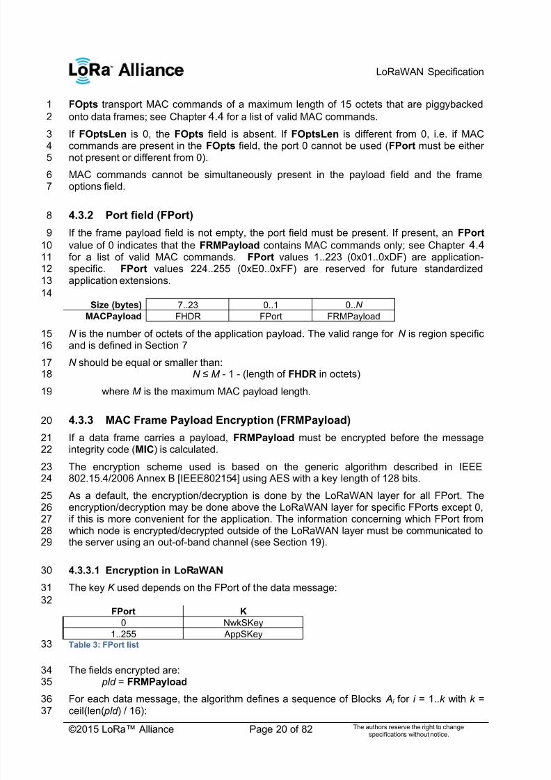
FOpts transport MAC commands of a maximum length of 15 octets that are piggybacked1
onto data frames; see Chapter 4.4 for a list of valid MAC commands.2
If FOptsLen is 0, the FOpts field is absent. If FOptsLen is different from 0, i.e. if MAC3commands are present in the FOpts field, the port 0 cannot be used (FPort must be either4not present or different from 0).5
MAC commands cannot be simultaneously present in the payload field and the frame6options field.7
4.3.2 Port field (FPort)8
If the frame payload field is not empty, the port field must be present. If present, an FPort 9
value of 0 indicates that the FRMPayload contains MAC commands only; see Chapter 4.4 10for a list of valid MAC commands. FPort values 1..223 (0x01..0xDF) are application-11
specific. FPort values 224..255 (0xE0..0xFF) are reserved for future standardized12 application extensions.13
14Size (bytes) 7..23 0..1 0..N
MACPayload FHDR FPort FRMPayload
N is the number of octets of the application payload. The valid range for N is region specific15and is defined in Section 716
N should be equal or smaller than:17N ≤ M - 1 - (length of FHDR in octets)18
where M is the maximum MAC payload length.19
4.3.3 MAC Frame Payload Encryption (FRMPayload)20
If a data frame carries a payload, FRMPayload must be encrypted before the message21integrity code (MIC) is calculated.22
The encryption scheme used is based on the generic algorithm described in IEEE23802.15.4/2006 Annex B [IEEE802154] using AES with a key length of 128 bits.24
As a default, the encryption/decryption is done by the LoRaWAN layer for all FPort. The25encryption/decryption may be done above the LoRaWAN layer for specific FPorts except 0,26if this is more convenient for the application. The information concerning which FPort from27which node is encrypted/decrypted outside of the LoRaWAN layer must be communicated to28
the server using an out-of-band channel (see Section 19).29
4.3.3.1 Encryption in LoRaWAN30
The key K used depends on the FPort of the data message:31
32FPort K
0 NwkSKey
1..255 AppSKeyTable 3: FPort list33
The fields encrypted are:34
pld = FRMPayload 35For each data message, the algorithm defines a sequence of Blocks Ai for i = 1..k with k =36ceil(len( pld ) / 16):37

7/23/2019 LoRaWAN Specification 1R0
http://slidepdf.com/reader/full/lorawan-specification-1r0 21/82
LoRaWAN Specification
©2015 LoRa™ Alliance Page 21 of 82 The authors reserve the right to changespecifications without notice.
1Size (bytes) 1 4 1 4 4 1 1
A i 0x01 4 x 0x00 Dir DevAddr FCntUp orFCntDown
0x00 i
2
The direction field (Dir ) is 0 for uplink frames and 1 for downlink frames.3
The blocks Ai are encrypted to get a sequence S of blocks Si :45
Si = aes128_encrypt(K, Ai ) for i = 1..k6S = S1 | S2 | .. | Sk7
Encryption and decryption of the payload is done by truncating89
( pld | pad16) xor S10
to the first len( pld ) octets.11
4.3.3.2 Encryption above the LoRaWAN layer12
If the layers above LoRaWAN provide pre-encrypted FRMPayload to LoRaWAN on selected13ports (but not on FPort 0 which is reserved for MAC commands), LoRaWAN transfers14FRMPayload from MACPayload to the application and FRMPayload from the application to15MACPayload without any modification of FRMPayload.16
17
4.4 Message Integrity Code (MIC)18
The message integrity code (MIC) is calculated over all the fields in the message.1920
msg = MHDR | FHDR | FPort | FRMPayload 21
whereby len(msg ) denotes the length of the message in octets.22
The MIC is calculated as follows [RFC4493]:2324
cmac = aes128_cmac(NwkSKey, B0 | msg )25MIC = cmac [0..3]26
27whereby the block B0 is defined as follows: 28Size (bytes) 1 4 1 4 4 1 1
B 0 0x49 4 x 0x00 Dir DevAddr FCntUp orFCntDown
0x00 len(msg )
29
The direction field (Dir ) is 0 for uplink frames and 1 for downlink frames.30

7/23/2019 LoRaWAN Specification 1R0
http://slidepdf.com/reader/full/lorawan-specification-1r0 22/82
LoRaWAN Specification
©2015 LoRa™ Alliance Page 22 of 82 The authors reserve the right to changespecifications without notice.
5 MAC Commands1
For network administration, a set of MAC commands may be exchanged exclusively2between the network server and the MAC layer on an end-device. MAC layer commands3are never visible to the application or the application server or the application running on the4end-device.5
A single data frame can contain any sequence of MAC commands, either piggybacked in the6FOpts field or, when sent as a separate data frame, in the FRMPayload field with the FPort 7field being set to 0. Piggybacked MAC commands are always sent without encryption and8must not exceed 15 octets. MAC commands sent as FRMPayload are always encrypted9and must not exceed the maximum FRMPayload length.10
Note: MAC commands whose content shall not be disclosed to an11eavesdropper must be sent in the FRMPayload of a separate data12
message.13 A MAC command consists of a command identifier (CID) of 1 octet followed by a possibly14empty command-specific sequence of octets.15
16CID Command Transmitted by Short Description
End-device
Gateway
0x02 LinkCheckReq x Used by an end-device to validate itsconnectivity to a network.
0x02 L inkCheckAns x Answer to LinkCheckReq command.Contains the received signal power
estimation indicating to the end-device the
quality of reception (link margin).0x03 LinkADRReq x Requests the end-device to change data
rate, transmit power, repetition rate orchannel.
0x03 L inkADRAns x Acknowledges the LinkRateReq.
0x04 DutyCycleReq x Sets the maximum aggregated transmitduty-cycle of a device
0x04 DutyCycleAns x Acknowledges a DutyCycleReq command
0x05 RXParamSetupReq x Sets the reception slots parameters
0x05 RXParamSetupAns x Acknowledges a RXSetupReq command
0x06 DevStatusReq x Requests the status of the end-device
0x06 DevStatusAns x Returns the status of the end-device, namelyits battery level and its demodulation margin
0x07 NewChannelReq x Creates or modifies the definition of a radiochannel
0x07 NewChannelAns x Acknowledges a NewChannelReq command
0x08 RXTimingSetupReq x Sets the timing of the of the reception slots
0x08 RXTimingSetupAns x Acknowledge RXTimingSetupReq command
0x80to
0xFF
Proprietary x x Reserved for proprietary network commandextensions
Table 4: MAC commands17
Note: The length of a MAC command is not explicitly given and must18be implicitly known by the MAC implementation. Therefore unknown19MAC commands cannot be skipped and the first unknown MAC20command terminates the processing of the MAC command sequence.21It is therefore advisable to order MAC commands according to the22

7/23/2019 LoRaWAN Specification 1R0
http://slidepdf.com/reader/full/lorawan-specification-1r0 23/82
LoRaWAN Specification
©2015 LoRa™ Alliance Page 23 of 82 The authors reserve the right to changespecifications without notice.
version of the LoRaWAN specification which has introduced a MAC1command for the first time. This way all MAC commands up to the2version of the LoRaWAN specification implemented can be processed3
even in the presence of MAC commands specified only in a version of4the LoRaWAN specification newer than that implemented.5
6
Note: Any values adjusted by the network server (e.g., RX2, new or7adjusted channels definitions) remain only valid until the next join of8the end-device. Therefore after each successful join procedure the9end-device uses the default parameters again and it is up to the10network server to re-adjust the values again as needed. 11
5.1 Link Check commands (LinkCheckReq, LinkCheckAns)12
13
With the LinkCheckReq command, an end-device may validate its connectivity with the14network. The command has no payload.15
When a LinkCheckReq is received by the network server via one or multiple gateways, it16responds with a LinkCheckAns command.17
18Size (bytes) 1 1
LinkCheckAns Payload Margin GwCnt
The demodulation margin (Margin) is an 8-bit unsigned integer in the range of 0..25419indicating the link margin in dB of the last successfully received LinkCheckReq command.20
A value of ―0‖ means that the frame was received at the demodulation floor (0 dB or no21margin) while a value of ―20‖, for example, means that the frame reached the gateway 20 dB22above the demodulation floor. Value ―255‖ is reserved. 23
The gateway count (GwCnt) is the number of gateways that successfully received the last24LinkCheckReq command.25
5.2 Link ADR commands (LinkADRReq, LinkADRAns)26
27
With the LinkADRReq command, the network server requests an end-device to perform a28rate adaptation.29
30 Size (bytes) 1 2 1
LinkADRReq Payload DataRate_TXPower ChMask Redundancy
31Bits [7:4] [3:0]
DataRate_TXPower DataRate TXPower
32
The requested date rate (DataRate) and TX output power (TXPower ) are region-specific33and are encoded as indicated in Chapter 7. 34

7/23/2019 LoRaWAN Specification 1R0
http://slidepdf.com/reader/full/lorawan-specification-1r0 24/82
LoRaWAN Specification
©2015 LoRa™ Alliance Page 24 of 82 The authors reserve the right to changespecifications without notice.
The channel mask (ChMask) encodes the channels usable for uplink access as follows with1bit 0 corresponding to the LSB:2
Bit# Usable channels0 Channel 1
1 Channel 2
.. ..
15 Channel 16Table 5: Channel state table3
A bit in the ChMask field set to 1 means that the corresponding channel can be used for4uplink transmissions if this channel allows the data rate currently used by the end-device. A5bit set to 0 means the corresponding channels should be avoided.6
7Bits 7 [6:4] [3:0]
Redundancy bits RFU ChMaskCntl NbRep
In the Redundancy bits the number of repetitions (NbRep) field is the number of repetition8for each uplink message. This applies only to ―unconfirmed‖ uplink frames. The default value9is 1. The valid range is [1:15]. If NbRep==0 is received the end-device should use the10default value. This field can be used by the network manager to control the redundancy of11the node uplinks to obtain a given Quality of Service. The end-device performs frequency12hopping as usual between repeated transmissions, it does wait after each repetition until the13receive windows have expired.14
The channel mask control (ChMaskCntl) field controls the interpretation of the previously15defined ChMask bit mask. This field will only be non-zero values in networks where more16
than 16 channels are implemented. It controls the block of 16 channels to which the17 ChMask applies. It can also be used to globally turn on or off all channels using specific18modulation. This field usage is region specific and is defined in Chapter 7. 19
The channel frequencies are region-specific and they are defined in Chapter 6. An end-20device answers to a LinkADRReq with a LinkADRAns command.21
22Size (bytes) 1
LinkADRAns Payload Status
2324
Bits [7:3] 2 1 0
Status bits RFU Power ACK Data rate ACK Channel mask ACK
25

7/23/2019 LoRaWAN Specification 1R0
http://slidepdf.com/reader/full/lorawan-specification-1r0 25/82
LoRaWAN Specification
©2015 LoRa™ Alliance Page 25 of 82 The authors reserve the right to changespecifications without notice.
The LinkADRAns Status bits have the following meaning:12
Bit = 0 Bit = 1Channel mask ACK The channel mask sentenables a yet undefinedchannel. The command wasdiscarded and the end-device state was notchanged.
The channel mask sent wassuccessfully interpreted. Allcurrently defined channelstates were set according tothe mask.
Data rate ACK The data rate requested isunknown to the end-deviceor is not possible given thechannel mask provided (notsupported by any of the
enabled channels). Thecommand was discarded andthe end-device state was notchanged.
The data rate wassuccessfully set.
Power ACK The requested power level isnot implemented in thedevice. The command wasdiscarded and the end-device state was notchanged.
The power level wassuccessfully set.
Table 6: LinkADRAns status bits signification3
If any of those three bits equals 0, the command did not succeed and the node has kept the4previous state.5
5.3 End-Device Transmit Duty Cycle (DutyCycleReq, DutyCycleAns)6
The DutyCycleReq command is used by the network coordinator to limit the maximum7aggregated transmit duty cycle of an end-device. The aggregated transmit duty cycle8corresponds to the transmit duty cycle over all sub-bands.9
10Size (bytes) 1
DutyCycleReq Payload MaxDCycle
11The maximum end-device transmit duty cycle allowed is:12
The valid range for MaxDutyCycle is [0 : 15]. A value of 0 corresponds to ―no duty cycle13limitation‖ except the one set by the regional regulation.14
A value of 255 means that the end-device shall become silent immediately. It is equivalent to15remotely switching off the end-device.16
An end-device answers to a DutyCycleReq with a DutyCycleAns command. The17DutyCycleAns MAC reply does not contain any payload.18

7/23/2019 LoRaWAN Specification 1R0
http://slidepdf.com/reader/full/lorawan-specification-1r0 26/82
LoRaWAN Specification
©2015 LoRa™ Alliance Page 26 of 82 The authors reserve the right to changespecifications without notice.
5.4 Receive Windows Parameters (RXParamSetupReq,1
RXParamSetupAns)2
The RXParamSetupReq command allows a change to the frequency and the data rate set3for the second receive window (RX2) following each uplink. The command also allows to4program an offset between the uplink and the RX1 slot downlink data rates.5
6Size (bytes) 1 3
RX2SetupReq Payload DLsettings Frequency
7Bits 7 6:4 3:0
DLsettings RFU RX1DRoffset RX2DataRate
8The RX1DRoffset field sets the offset between the uplink data rate and the downlink data9rate used to communicate with the end-device on the first reception slot (RX1). As a default10
this offset is 0.. The offset is used to take into account maximum power density constraints11for base stations in some regions and to balance the uplink and downlink radio link margins.12
The data rate (RX2DataRate) field defines the data rate of a downlink using the second13receive window following the same convention as the LinkADRReq command (0 means14DR0/125kHz for example). The frequency (Frequency) field corresponds to the frequency of15the channel used for the second receive window, whereby the frequency is coded following16the convention defined in the NewChannelReq command.17
The RXParamSetupAns command is used by the end-device to acknowledge the reception18of RXParamSetupReq command. The payload contains a single status byte.19
Size (bytes) 1
RX2SetupAns Payload Status
20The status (Status) bits have the following meaning.21
Bits 7:3 2 1 0
Statusbits
RFU RX1DRoffset ACK
RX2 Data rate ACK
Channel ACK
22Bit = 0 Bit = 1
Channel ACK The frequency requested isnot usable by the end-device.
RX2 slot channel wassuccessfully set
RX2 Data rate ACK The data rate requested isunknown to the end-device.
RX2 slot data rate wassuccessfully set
RX1DRoffset ACK the uplink/downlink data rateoffset for RX1 slot is not inthe allowed range
RX1DRoffset wassuccessfully set
Table 7: RX2SetupAns status bits signification23
If either of the 3 bits is equal to 0, the command did not succeed and the previous24parameters are kept.25
26

7/23/2019 LoRaWAN Specification 1R0
http://slidepdf.com/reader/full/lorawan-specification-1r0 27/82
LoRaWAN Specification
©2015 LoRa™ Alliance Page 27 of 82 The authors reserve the right to changespecifications without notice.
5.5 End-Device Status (DevStatusReq, DevStatusAns)1
With the DevStatusReq command a network server may request status information from an2
end-device. The command has no payload. If a DevStatusReq is received by an end-3device, it responds with a DevStatusAns command.4
Size (bytes) 1 1
DevStatusAns Payload Battery Margin
The battery level (Battery) reported is encoded as follows:5Battery Description
0 The end-device is connected to an externalpower source.
1..254 The battery level, 1 being at minimum and254 being at maximum
255 The end-device was not able to measure thebattery level.
Table 8: Battery level decoding6
The margin (Margin) is the demodulation signal-to-noise ratio in dB rounded to the nearest7integer value for the last successfully received DevStatusReq command. It is a signed8integer of 6 bits with a minimum value of -32 and a maximum value of 31.9
Bits 7:6 5:0
Status RFU Margin
5.6 Creation / Modification of a Channel (NewChannelReq,10
NewChannelAns)11
12The NewChannelReq command can be used to either modify the parameters of an existing13channel or to create a new one. The command sets the center frequency of the new channel14and the range of data rates usable on this channel:15
Size (bytes) 1 3 1
NewChannelReq Payload ChIndex Freq DrRange
16
The channel index (ChIndex) is the index of the channel being created or modified.17Depending on the region and frequency band used, the LoRaWAN specification imposes18default channels which must be common to all devices and cannot be modified by the19NewChannelReq command (cf. Chapter 6). If the number of default channels is N , the20default channels go from 0 to N -1, and the acceptable range for ChIndex is N to 15. A21
device must be able to handle at least 16 different channel definitions. In certain region the22device may have to store more than 16 channel definitions.23
24
The frequency (Freq) field is a 24 bits unsigned integer. The actual channel frequency in Hz25is 100 x Freq whereby values representing frequencies below 100 MHz are reserved for26future use. This allows setting the frequency of a channel anywhere between 100 MHz to271.67 GHz in 100 Hz steps. A Freq value of 0 disables the channel. The end-device has to28check that the frequency is actually allowed by its radio hardware and return an error29otherwise.30
31
The data-rate range (DrRange) field specifies the data-rate range allowed for this channel.32
The field is split in two 4-bit indexes:33Bits 7:4 3:0
DrRange MaxDR MinDR

7/23/2019 LoRaWAN Specification 1R0
http://slidepdf.com/reader/full/lorawan-specification-1r0 28/82
LoRaWAN Specification
©2015 LoRa™ Alliance Page 28 of 82 The authors reserve the right to changespecifications without notice.
1
Following the convention defined in Section 5.2 the minimum data rate (MinDR) subfield2
designate the lowest data rate allowed on this channel. For example 0 designates DR0 / 1253 kHz. Similarly, the maximum data rate (MaxDR) designates the highest data rate. For4example, DrRange = 0x77 means that only 50 kbps GFSK is allowed on a channel and5DrRange = 0x50 means that DR0 / 125 kHz to DR5 / 125 kHz are supported.6
The newly defined channel is enabled and can immediately be used for communication.7
The end-device acknowledges the reception of a NewChannelReq by sending back a8NewChannelAns command. The payload of this message contains the following9information:10
Size (bytes) 1
NewChannelAns Payload Status
11
The status (Status) bits have the following meaning:12Bits 7:2 1 0
Status RFU Data raterange ok
Channelfrequency ok
13Bit = 0 Bit = 1
Data rate range ok The designated data raterange exceeds the onescurrently defined for this end-device
The data rate range iscompatible with thepossibilities of the end-device
Channel frequency ok The device cannot use this
frequency
The device is able to use this
frequency.Table 9: NewChannelAns status bits signification14
If either of those 2 bits equals 0, the command did not succeed and the new channel has not15been created.16
5.7 Setting delay between TX and RX (RXTimingSetupReq,17
RXTimingSetupAns)18
The RXTimingSetupReq command allows configuring the delay between the end of the TX19uplink and the opening of the first reception slot. The second reception slot opens one20second after the first reception slot.21
Size (bytes) 1RXTimingSetupReq Payload Settings
22
The delay (Delay) field specifies the delay. The field is split in two 4-bit indexes:23Bits 7:4 3:0
Settings RFU Del
24
The delay is expressed in seconds. Del 0 is mapped on 1 s.25Del Delay [s]
0 1
1 1
2 23 3
.. ..

7/23/2019 LoRaWAN Specification 1R0
http://slidepdf.com/reader/full/lorawan-specification-1r0 29/82
LoRaWAN Specification
©2015 LoRa™ Alliance Page 29 of 82 The authors reserve the right to changespecifications without notice.
15 15Table 10: Del mapping table1
2
An end device answers RXTimingSetupReq with RXTimin gSetupAn s with no payload.3

7/23/2019 LoRaWAN Specification 1R0
http://slidepdf.com/reader/full/lorawan-specification-1r0 30/82
LoRaWAN Specification
©2015 LoRa™ Alliance Page 30 of 82 The authors reserve the right to changespecifications without notice.
6 End-Device Activation1
To participate in a LoRaWAN network, each end-device has to be personalized and2activated.3
Activation of an end-device can be achieved in two ways, either via Over-The-Air4Activation (OTAA) when an end-device is deployed or reset, or via Activation By5Personalization (ABP) in which the two steps of end-device personalization and activation6are done as one step.7
6.1 Data Stored in the End-device after Activation8
After activation, the following information is stored in the end-device: a device address9(DevAddr ), an application identifier (AppEUI), a network session key (NwkSKey), and an10application session key (AppSKey).11
6.1.1 End-device address (DevAddr)12
The DevAddr consists of 32 bits identifies the end-device within the current network. Its13format is as follows:14
Bit# [31..25] [24..0]
DevAddr bits NwkID NwkAddr
The most significant 7 bits are used as network identifier (NwkID) to separate addresses of15territorially overlapping networks of different network operators and to remedy roaming16issues. The least significant 25 bits, the network address (NwkAddr ) of the end-device, can17be arbitrarily assigned by the network manager.18
6.1.2 Application identifier (AppEUI)19
The AppEUI is a global application ID in IEEE EUI64 address space that uniquely identifies20the application provider (i.e., owner) of the end-device.21
The AppEUI is stored in the end-device before the activation procedure is executed.22
6.1.3 Network session key (NwkSKey)23
The NwkSKey is a network session key specific for the end-device. It is used by both the24network server and the end-device to calculate and verify the MIC (message integrity code)25
of all data messages to ensure data integrity. It is further used to encrypt and decrypt the26payload field of a MAC-only data messages.27
6.1.4 Application session key (AppSKey)28
The AppSKey is an application session key specific for the end-device. It is used by both29the network server and the end-device to encrypt and decrypt the payload field of30application-specific data messages. It is also used to calculate and verify an application-31level MIC that may be included in the payload of application-specific data messages.32
6.2 Over-the-Air Activation33
For over-the-air activation, end-devices must follow a join procedure prior to participating in34data exchanges with the network server. An end-device has to go through a new join35procedure every time it has lost the session context information.36
7/23/2019 LoRaWAN Specification 1R0
http://slidepdf.com/reader/full/lorawan-specification-1r0 31/82
LoRaWAN Specification
©2015 LoRa™ Alliance Page 31 of 82 The authors reserve the right to changespecifications without notice.
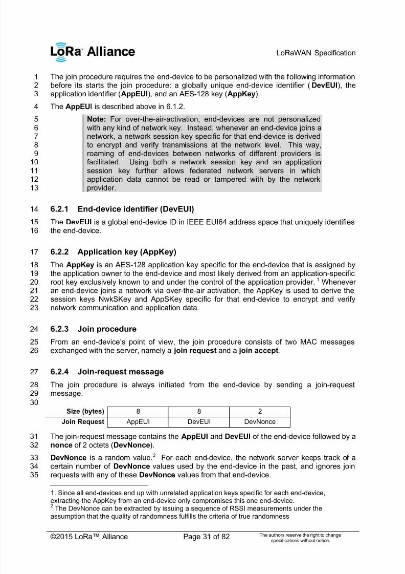
The join procedure requires the end-device to be personalized with the following information1before its starts the join procedure: a globally unique end-device identifier (DevEUI), the2application identifier (AppEUI), and an AES-128 key (AppKey).3
The AppEUI is described above in 6.1.2. 4
Note: For over-the-air-activation, end-devices are not personalized5with any kind of network key. Instead, whenever an end-device joins a6network, a network session key specific for that end-device is derived7to encrypt and verify transmissions at the network level. This way,8roaming of end-devices between networks of different providers is9facilitated. Using both a network session key and an application10session key further allows federated network servers in which11application data cannot be read or tampered with by the network12provider.13
6.2.1 End-device identifier (DevEUI)14
The DevEUI is a global end-device ID in IEEE EUI64 address space that uniquely identifies15the end-device.16
6.2.2 Application key (AppKey)17
The AppKey is an AES-128 application key specific for the end-device that is assigned by18the application owner to the end-device and most likely derived from an application-specific19root key exclusively known to and under the control of the application provider. 1 Whenever20an end-device joins a network via over-the-air activation, the AppKey is used to derive the21
session keys NwkSKey and AppSKey specific for that end-device to encrypt and verify22 network communication and application data.23
6.2.3 Join procedure24
From an end-device‘s point of view, the join procedure consists of two MAC messages25exchanged with the server, namely a join request and a join accept.26
6.2.4 Join-request message27
The join procedure is always initiated from the end-device by sending a join-request28message.29
30Size (bytes) 8 8 2
Join Request AppEUI DevEUI DevNonce
The join-request message contains the AppEUI and DevEUI of the end-device followed by a31nonce of 2 octets (DevNonce).32
DevNonce is a random value.2 For each end-device, the network server keeps track of a33certain number of DevNonce values used by the end-device in the past, and ignores join34requests with any of these DevNonce values from that end-device.35
1. Since all end-devices end up with unrelated application keys specific for each end-device,
extracting the AppKey from an end-device only compromises this one end-device. 2 The DevNonce can be extracted by issuing a sequence of RSSI measurements under the
assumption that the quality of randomness fulfills the criteria of true randomness

7/23/2019 LoRaWAN Specification 1R0
http://slidepdf.com/reader/full/lorawan-specification-1r0 32/82
LoRaWAN Specification
©2015 LoRa™ Alliance Page 32 of 82 The authors reserve the right to changespecifications without notice.
Note: This mechanism prevents replay attacks by sending previously1recorded join-request messages with the intention of disconnecting the2respective end-device from the network.3
The message integrity code (MIC) value (see Chapter 4 for MAC message description) for a4 join-request message is calculated as follows:1 5
6cmac = aes128_cmac(AppKey, MHDR | AppEUI | DevEUI | DevNonce)7MIC = cmac [0..3]8
The join-request message is not encrypted.9
6.2.5 Join-accept message10
The network server will respond to the join-request message with a join-accept message if11the end-device is permitted to join a network. The join-accept message is sent like a normal12downlink but uses delays JOIN_ACCEPT_DELAY1 or JOIN_ACCEPT_DELAY2 (instead of13RECEIVE_DELAY1 and RECEIVE_DELAY2, respectively). The channel frequency and data14rate used for these two receive windows are identical to the one used for the RX1 and RX215receive windows described in the ―receive windows‖ section of the ―Physical Layer ‖ chapter 16
No response is given to the end-device if the join request is not accepted.17
The join-accept message contains an application nonce (AppNonce) of 3 octets, a network18identifier (NetID), an end-device address (DevAddr ), a delay between TX and RX19(RxDelay) and an optional list of channel frequencies (CFList) for the network the end-20device is joining. The CFList option is region specific and is defined in Section 7. 21
22
Size (bytes) 3 3 4 1 1 (16) Optional
Join Accept AppNonce NetID DevAddr DLSettings RxDelay CFList
The AppNonce is a random value or some form of unique ID provided by the network server23and used by the end-device to derive the two session keys NwkSKey and AppSKey as24follows:3 25NwkSKey = aes128_encrypt(AppKey, 0x01 | AppNonce | NetID | DevNonce | pad16)26 AppSKey = aes128_encrypt(AppKey, 0x02 | AppNonce | NetID | DevNonce | pad16)27
The MIC value for a join-accept message is calculated as follows:4 28cmac = aes128_cmac(AppKey,29
MHDR | AppNonce | NetID | DevAddr | RFU | RxDelay | CFList)30
MIC = cmac [0..3]31The join-accept message itself is encrypted with the AppKey as follows:32aes128_decrypt(AppKey, AppNonce | NetID | DevAddr | RFU | RxDelay | CFList | MIC)33
Note: The network server uses an AES decrypt operation in ECB34mode to encrypt the join-accept message so that the end-device can35use an AES encrypt operation to decrypt the message. This way an36end-device only has to implement AES encrypt but not AES decrypt.37
38
1
[RFC4493]3 The pad16 function appends zero octets so that the length of the data is a multiple of 16.
4 [RFC4493]
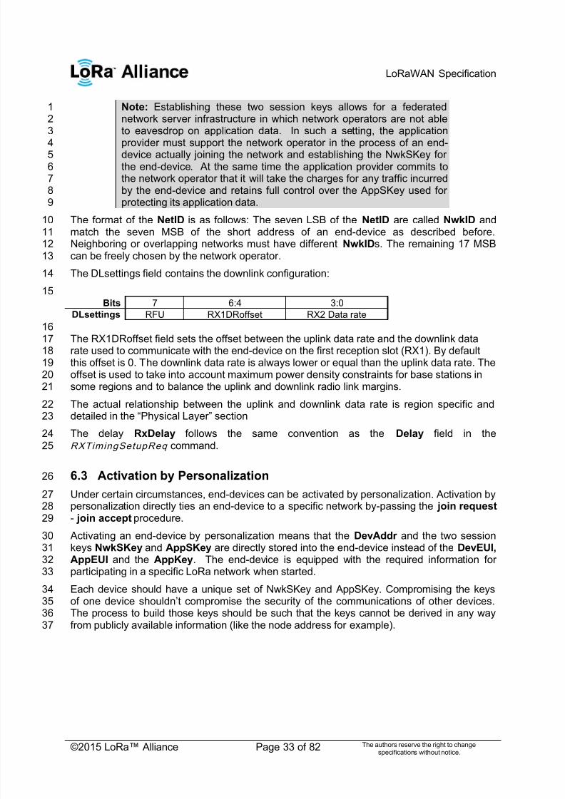
7/23/2019 LoRaWAN Specification 1R0
http://slidepdf.com/reader/full/lorawan-specification-1r0 33/82
LoRaWAN Specification
©2015 LoRa™ Alliance Page 33 of 82 The authors reserve the right to changespecifications without notice.
Note: Establishing these two session keys allows for a federated1network server infrastructure in which network operators are not able2to eavesdrop on application data. In such a setting, the application3
provider must support the network operator in the process of an end-4device actually joining the network and establishing the NwkSKey for5the end-device. At the same time the application provider commits to6the network operator that it will take the charges for any traffic incurred7by the end-device and retains full control over the AppSKey used for8protecting its application data.9
The format of the NetID is as follows: The seven LSB of the NetID are called NwkID and10match the seven MSB of the short address of an end-device as described before.11Neighboring or overlapping networks must have different NwkIDs. The remaining 17 MSB12can be freely chosen by the network operator.13
The DLsettings field contains the downlink configuration:14
15Bits 7 6:4 3:0
DLsettings RFU RX1DRoffset RX2 Data rate
16The RX1DRoffset field sets the offset between the uplink data rate and the downlink data17rate used to communicate with the end-device on the first reception slot (RX1). By default18this offset is 0. The downlink data rate is always lower or equal than the uplink data rate. The19offset is used to take into account maximum power density constraints for base stations in20some regions and to balance the uplink and downlink radio link margins.21
The actual relationship between the uplink and downlink data rate is region specific and22
detailed in the ―Physical Layer‖ section 23The delay RxDelay follows the same convention as the Delay field in the24RXTimingSetupReq command.25
6.3 Activation by Personalization26
Under certain circumstances, end-devices can be activated by personalization. Activation by27personalization directly ties an end-device to a specific network by-passing the join request 28- join accept procedure.29
Activating an end-device by personalization means that the DevAddr and the two session30keys NwkSKey and AppSKey are directly stored into the end-device instead of the DevEUI,31
AppEUI and the AppKey. The end-device is equipped with the required information for32participating in a specific LoRa network when started.33
Each device should have a unique set of NwkSKey and AppSKey. Compromising the keys34of one device shouldn‘t compromise the security of the communications of other devices. 35The process to build those keys should be such that the keys cannot be derived in any way36from publicly available information (like the node address for example).37

7/23/2019 LoRaWAN Specification 1R0
http://slidepdf.com/reader/full/lorawan-specification-1r0 34/82
LoRaWAN Specification
©2015 LoRa™ Alliance Page 34 of 82 The authors reserve the right to changespecifications without notice.
7 Physical Layer1
7.1 EU 863-870MHz ISM Band2
7.1.1 EU863-870 Preamble Format3
The following synchronization words should be used:45
Modulation Sync word Preamble length
LORA 0x34 8 symbols
GFSK 0xC194C1 5 bytesTable 11: EU863-870 synch words6
7.1.2 EU863-870 ISM Band channel frequencies7
In Europe, radio spectrum allocation is the ISM band is defined by ETSI [EN300.220].8
The network channels can be freely attributed by the network operator. However the three9following default channels must be implemented in every EU868MHz end-device. Those10channels are the minimum set that all network gateways should always be listening on.11
12Modulation Bandwidth [kHz] Channel
Frequency[MHz]
FSKBitrate orLoRa DR / Bitrate
NbChannels
Dutycycle
LoRa 125 868.10868.30868.50
DR0 toDR5
/ 0.3-5kbps
3 <1%
Table 12: EU863-870 default channels13
In order to access the physical medium the ETSI regulations impose some restrictions such14maximum time the transmitter can be on or the maximum time a transmitter can transmit per15hour. The ETSI regulations allow the choice of using either a duty-cycle limitation or a so-16called Listen Before Talk Adaptive Frequency Agility (LBT AFA) transmissions17management. The current LoRaWAN specification exclusively uses duty-cycled limited18transmissions to comply with the ETSI regulations.19
The LoRaWAN enforces a per sub-band duty-cycle limitation. Each time a frame is20transmitted in a given sub-band, the time of emission and the on-air duration of the frame21are recorded for this sub-band. The same sub-band cannot be used again during the next22Toff seconds where:23
During the unavailable time of a given sub-band, the device may still be able to transmit on24another sub-band. If all sub-bands are unavailable, the device has to wait before any further25transmission. The device adapts its channel hoping sequence according to the sub-band26availability.27
Example: A device just transmitted a 0.5 s long frame on one default channel. This channel28is in a sub-band allowing 1% duty-cycle. Therefore this whole sub-band (868 – 868.6) will be29unavailable for 49.5 s.30

7/23/2019 LoRaWAN Specification 1R0
http://slidepdf.com/reader/full/lorawan-specification-1r0 35/82
LoRaWAN Specification
©2015 LoRa™ Alliance Page 35 of 82 The authors reserve the right to changespecifications without notice.
EU868MHz ISM band end-devices should use the following default parameters1
Default radiated transmit output power: 14 dBm2
EU868Mhz end-devices should be capable of operating in the 863 to 870 MHz frequency3 band and should feature a channel data structure to store the parameters of at least 164channels. A channel data structure corresponds to a frequency and a set of data rates5usable on this frequency.6
The first three channels correspond to 868.1, 868.3, and 868.5 MHz / DR0 to DR5 and must7be implemented in every end-device. Those default channels cannot be modified through8the NewChannelReq command and guarantee a minimal common channel set between9end-devices and network gateways.10
The following table gives the list of frequencies that should be used by end-devices to11broadcast the JoinReq message. The JoinReq message transmit duty-cycle should never12exceed 0.1%13
14Modulation Bandwidth [kHz] Channel
Frequency[MHz]
FSKBitrate
or LoRaDR
/ Bitrate
NbChannels
Dutycycle
LoRa125 864.10
864.30864.50868.10868.30868.50
DR0 – DR5
/ 0.3-5kbps
6 <0.1%
Table 13: EU863-870 JoinReq Channel List15
7.1.3 EU863-870 Data Rate and End-point Output Power encoding16
The following encoding is used for Data Rate (DR) and End-point Output Power (TXPower)17in the EU863-870 band:18DataRate Configuration Indicative physical
bit rate [bit/s]TXPower Configuration
0 LoRa: SF12 / 125 kHz 250 0 20 dBm (ifsupported)
1 LoRa: SF11 / 125 kHz 440 1 14 dBm
2 LoRa: SF10 / 125 kHz 980 2 11 dBm
3 LoRa: SF9 / 125 kHz 1760 3 8 dBm4 LoRa: SF8 / 125 kHz 3125 4 5 dBm
5 LoRa: SF7 / 125 kHz 5470 5 2 dBm
6 LoRa: SF7 / 250 kHz 11000 6..15 RFU
7 FSK: 50 kbps 50000
8..15 RFUTable 14: Data rate and TX power table19
7.1.4 EU863-870 JoinAccept CFList2021
The EU 863-870 ISM band LoRaWAN implements an optional channel frequency list22(CFlist) of 16 octets in the JoinAccept message.23

7/23/2019 LoRaWAN Specification 1R0
http://slidepdf.com/reader/full/lorawan-specification-1r0 36/82
LoRaWAN Specification
©2015 LoRa™ Alliance Page 36 of 82 The authors reserve the right to changespecifications without notice.
In this case the CFList is a list of five channel frequencies for the channels four to eight1whereby each frequency is encoded as a 24 bits unsigned integer (three octets). All these2channels are usable for DR0 to DR5 125kHz LoRa modulation. The list of frequencies is3
followed by a single RFU octet for a total of 16 octets.4
5Size
(bytes)3 3 3 3 3 1
CFList Freq Ch4 Freq Ch5 Freq Ch6 Freq CN7 Freq Ch8 RFU
The actual channel frequency in Hz is 100 x frequency whereby values representing6frequencies below 100 Mhz are reserved for future use. This allows setting the frequency of7a channel anywhere between 100 MHz to 1.67 GHz in 100 Hz steps. Unused channels have8a frequency value of 0. The CFList is optional and its presence can be detected by the9length of the join-accept message. If present, the CFList replaces all the previous channels10stored in the end-device apart from the three default channels as defined in Chapter 6. The11newly defined channels are immediately enabled and usable by the end-device for12communication.13
7.1.5 EU863-870 LinkAdrReq command14
The EU863-870 LoRaWAN only supports a maximum of 16 channels. When ChMaskCntl 15field is 0 the ChMask field individually enables/disables each of the 16 channels.16
17ChMaskCntl ChMask applies to
0 Channels 1 to 16
1 RFU
.. ..
4 RFU
5 RFU
6 All channels ONThe device should enable all currently definedchannels independently of the ChMask field
value.
7 RFUTable 15: ChMaskCntl value table18
If the ChMask field value is one of values meaning RFU, the end-device should reject the19command and unset the ―Channel mask ACK‖ bit in its response. 20
7.1.6 EU863-870 Maximum payload size21
The maximum MACPayload size length (M) is given by the following table. It is derived from22limitation of the PHY layer depending on the effective modulation rate used taking into23account a possible repeater encapsulation layer. The maximum application payload length in24the absence of the optional FOpt control field (N ) is also given for information only. The25value of N might be smaller if the FOpt field is not empty:26
27DataRate M N
0 59 51
1 59 51
2 59 513 123 115
4 230 222

7/23/2019 LoRaWAN Specification 1R0
http://slidepdf.com/reader/full/lorawan-specification-1r0 37/82
LoRaWAN Specification
©2015 LoRa™ Alliance Page 37 of 82 The authors reserve the right to changespecifications without notice.
5 230 222
6 230 222
7 230 222
8:15 Not definedTable 16: EU863-870 maximum payload size1
If the end-device will never operate with a repeater then the maximum application payload2length in the absence of the optional FOpt control field should be:3
4DataRate M N
0 59 51
1 59 51
2 59 51
3 123 115
4 250 242
5 250 242
6 250 242
7 250 242
8:15 Not definedTable 17 : EU863-870 maximum payload size (not repeater compatible)5
7.1.7 EU863-870 Receive windows6
The RX1 receive window uses the same channel than the preceding uplink. The data rate is7a function of the uplink data rate and the RX1DROffset as given by the following table. The8allowed values for RX1DROffset are in the [0:5] range. Values in the [6:7] range are9
reserved for future use.10
11
12RX1DROffset 0 1 2 3 4 5
Upstream data rate Downstream data rate in RX1 slot
DR0 DR0 DR0 DR0 DR0 DR0 DR0
DR1 DR1 DR0 DR0 DR0 DR0 DR0
DR2 DR2 DR1 DR0 DR0 DR0 DR0
DR3 DR3 DR2 DR1 DR0 DR0 DR0
DR4 DR4 DR3 DR2 DR1 DR0 DR0
DR5 DR5 DR4 DR3 DR2 DR1 DR0
DR6 DR6 DR5 DR4 DR3 DR2 DR1
DR7 DR7 DR6 DR5 DR4 DR3 DR2
13
The RX2 receive window uses a fixed frequency and data rate. The default parameters are14869.525 MHz / DR0 (SF12, 125 kHz)15
7.1.8 EU863-870 Default Settings16
The following parameters are recommended values for the EU863-870Mhz band.17
RECEIVE_DELAY1 1 s18RECEIVE_DELAY2 2 s (must be RECEIVE_DELAY1 + 1s)19JOIN_ACCEPT_DELAY1 5 s20

7/23/2019 LoRaWAN Specification 1R0
http://slidepdf.com/reader/full/lorawan-specification-1r0 38/82
LoRaWAN Specification
©2015 LoRa™ Alliance Page 38 of 82 The authors reserve the right to changespecifications without notice.
JOIN_ACCEPT_DELAY2 6 s1MAX_FCNT_GAP 163842 ADR_ACK_LIMIT 643
ADR_ACK_DELAY 324 ACK_TIMEOUT 2 +/- 1 s (random delay between 1 and 3 seconds)5
If the actual parameter values implemented in the end-device are different from those default6values (for example the end-device uses a longer RECEIVE_DELAY1 and7RECEIVE_DELAY2 latency), those parameters must be communicated to the network8server using an out-of-band channel during the end-device commissioning process. The9network server may not accept parameters different from those default values.10
11

7/23/2019 LoRaWAN Specification 1R0
http://slidepdf.com/reader/full/lorawan-specification-1r0 39/82
LoRaWAN Specification
©2015 LoRa™ Alliance Page 39 of 82 The authors reserve the right to changespecifications without notice.
7.2 US 902-928MHz ISM Band1
7.2.1 US902-928 Preamble Format2
The following synchronization words should be used:34
Modulation Sync word Preamble length
LORA 0x34 8 symbols
LoRaWAN does not make use of GFSK modulation in the US902-928 ISM band.5
7.2.2 US902-928 Channel Frequencies6
The 915 MHz ISM Band shall be divided into the following channel plans.7
Upstream – 64 channels numbered 0 to 63 utilizing LoRa 125 kHz BW varying from8DR0 toDR3 starting at 902.3 MHz and incrementing linearly by 200 kHz to 914.99MHz10
Upstream – 8 channels numbered 64 to 71 utilizing LoRa 500 kHz BW at DR411starting at 903.0 MHz and incrementing linearly by 1.6 MHz to 914.2 MHz12
Downstream – 8 channels numbered 0 to 7 utilizing LoRa 500 kHz BW at DR10 to13DR13) starting at 923.3 MHz and incrementing linearly by 600 kHz to 927.5 MHz14
15
16Figure 10: US902-928 channel frequencies17
915 MHz ISM band end-devices should use the following default parameters:18
Default radiated transmit output power: 20 dBm19o Devices, when transmitting with 125 kHz BW may use a maximum of20
+30 dBm. The transmission should never last more than 400 ms.21o Devices, when transmitting with 500 kHz BW may use a maximum of22
+26 dBm23
US902-928 end-devices should be capable of operating in the 902 to 928 MHz frequency24band and should feature a channel data structure to store the parameters of 72 channels. A25channel data structure corresponds to a frequency and a set of data rates usable on this26frequency.27
If using the over-the-air activation procedure, the end-device should broadcast the JoinReq28message alternatively on a random 125 kHz channel amongst the 64 channels defined using29DR0 and a random 500 kHz channel amongst the 8 channels defined using DR4. The end-30device should change channel for every transmission.31
7.2.3 US902-928 Data Rate and End-point Output Power encoding32
The following encoding is used for Data Rate (DR) and End-point Output Power (TXPower )33in the US902-928 band:34
903.0902.3 904.6 914.2
….
923.3 923.9 927.5
….
8x downlink channels64 + 8 uplink channels

7/23/2019 LoRaWAN Specification 1R0
http://slidepdf.com/reader/full/lorawan-specification-1r0 40/82
LoRaWAN Specification
©2015 LoRa™ Alliance Page 40 of 82 The authors reserve the right to changespecifications without notice.
1DataRate Configuration Indicative
physical bit
rate [bit/sec]
TXPower
Configuration
0 LoRa: SF10 / 125 kHz 980 0 30 dBm – 2*TXpower
1 LoRa: SF9 / 125 kHz 1760 1 28 dBm
2 LoRa: SF8 / 125 kHz 3125 2 26 dBm
3 LoRa: SF7 / 125 kHz 5470 3 : 9 ….
4 LoRa: SF8 / 500 kHz 12500 10 10 dBm
5:7 RFU 11:15 RFU
8 LoRa: SF12 / 500 kHz 980
9 LoRa: SF11 / 500 kHz 1760
10 LoRa: SF10 / 500 kHz 3900
11 LoRa: SF9 / 500 kHz 7000
12 LoRa: SF8 / 500 kHz 12500
13 LoRa: SF7 / 500 kHz 2190014:15 RFU
Table 18: Data rate and TX power table (Rem: DR4 is identical to DR12, DR8..13 must be implemented in2end-devices and are reserved for future applications)3
7.2.4 US902-928 JoinResp CFList4
The US902-928 LoRaWAN does not support the use of the optional CFlist appended to the5JoinResp message. If the CFlist is not empty it is ignored by the end-device.6
7.2.5 US902-928 LinkAdrReq command7
For the US902-928 version the ChMaskCntl field of the LinkADRReq command has the8following meaning:9
10ChMaskCntl ChMask applies to
0 Channels 0 to 15
1 Channels 16 to 31
.. ..
4 Channels 64 to 71
5 RFU
6 All 125 kHz ONChMask applies tochannels 65 to 72
7 All 125 kHz OFFChMask applies tochannels 65 to 72
Table 19: ChMaskCntl value table11
If ChMaskCntl = 6 (resp 7) then 125 kHz channels are enabled (resp disabled).12Simultaneously the channels 64 to 71 are set according to the ChMask bit mask.13
Note: FCC regulation requires hopping over at least 50 channels when14using maximum output power. It is possible to have end-devices with15less channels (at least six 125 kHz channels) when limiting the end-16device transmit power to 21 dBm.17

7/23/2019 LoRaWAN Specification 1R0
http://slidepdf.com/reader/full/lorawan-specification-1r0 41/82
LoRaWAN Specification
©2015 LoRa™ Alliance Page 41 of 82 The authors reserve the right to changespecifications without notice.
7.2.6 US902-928 Maximum payload size1
The maximum MACPayload size length (M ) is given by the following table. It is derived from2
the maximum allowed transmission time at the PHY layer taking into account a possible3repeater encapsulation. The maximum application payload length in the absence of the4optional FOpt MAC control field (N ) is also given for information only. The value of N might5be smaller if the FOpt field is not empty:6
7DataRate M N
0 19 11
1 61 53
2 137 129
3 250 242
4 250 242
5:7 Not defined
8 41 339 117 109
10 230 222
11 230 222
12 230 222
13 230 222
14:15 Not definedTable 20: US902-928 maximum payload size (repeater compatible)8
The greyed lines correspond to the data rates that may be used by an end-device behind a9repeater.10
If the end-device will never operate under a repeater then the maximum application payload11 length in the absence of the optional FOpt control field should be:1213
DataRate M N
0 19 11
1 61 53
2 137 129
3 250 242
4 250 242
5:7 Not defined
8 61 53
9 137 129
10 250 24211 250 242
12 250 242
13 250 242
14:15 Not definedTable 21 : US902-928 maximum payload size (not repeater compatible)14
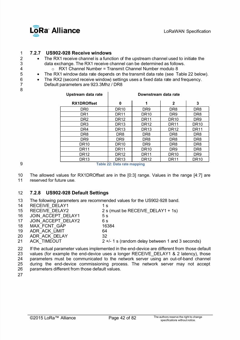
7/23/2019 LoRaWAN Specification 1R0
http://slidepdf.com/reader/full/lorawan-specification-1r0 42/82
LoRaWAN Specification
©2015 LoRa™ Alliance Page 42 of 82 The authors reserve the right to changespecifications without notice.
7.2.7 US902-928 Receive windows1
The RX1 receive channel is a function of the upstream channel used to initiate the2data exchange. The RX1 receive channel can be determined as follows.3
o RX1 Channel Number = Transmit Channel Number modulo 84
The RX1 window data rate depends on the transmit data rate (see Table 22 below).5
The RX2 (second receive window) settings uses a fixed data rate and frequency.6Default parameters are 923.3Mhz / DR87
8Upstream data rate Downstream data rate
RX1DROffset 0 1 2 3
DR0 DR10 DR9 DR8 DR8
DR1 DR11 DR10 DR9 DR8
DR2 DR12 DR11 DR10 DR9DR3 DR13 DR12 DR11 DR10
DR4 DR13 DR13 DR12 DR11
DR8 DR8 DR8 DR8 DR8
DR9 DR9 DR8 DR8 DR8
DR10 DR10 DR9 DR8 DR8
DR11 DR11 DR10 DR9 DR8
DR12 DR12 DR11 DR10 DR9
DR13 DR13 DR12 DR11 DR10Table 22: Data rate mapping9
The allowed values for RX1DROffset are in the [0:3] range. Values in the range [4:7] are10
reserved for future use.11
7.2.8 US902-928 Default Settings12
The following parameters are recommended values for the US902-928 band.13RECEIVE_DELAY1 1 s14RECEIVE_DELAY2 2 s (must be RECEIVE_DELAY1 + 1s)15JOIN_ACCEPT_DELAY1 5 s16JOIN_ACCEPT_DELAY2 6 s17MAX_FCNT_GAP 1638418 ADR_ACK_LIMIT 6419 ADR_ACK_DELAY 3220 ACK_TIMEOUT 2 +/- 1 s (random delay between 1 and 3 seconds)21
If the actual parameter values implemented in the end-device are different from those default22values (for example the end-device uses a longer RECEIVE_DELAY1 & 2 latency), those23parameters must be communicated to the network server using an out-of-band channel24during the end-device commissioning process. The network server may not accept25parameters different from those default values.26
27
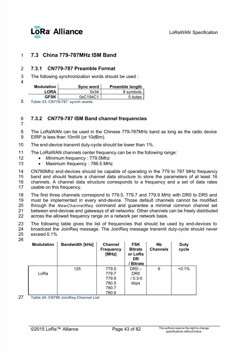
7/23/2019 LoRaWAN Specification 1R0
http://slidepdf.com/reader/full/lorawan-specification-1r0 43/82
LoRaWAN Specification
©2015 LoRa™ Alliance Page 43 of 82 The authors reserve the right to changespecifications without notice.
7.3 China 779-787MHz ISM Band1
7.3.1 CN779-787 Preamble Format2
The following synchronization words should be used :34
Modulation Sync word Preamble length
LORA 0x34 8 symbols
GFSK 0xC194C1 5 bytesTable 23: CN779-787 synch words5
7.3.2 CN779-787 ISM Band channel frequencies6
7
The LoRaWAN can be used in the Chinese 779-787MHz band as long as the radio device8EIRP is less than 10mW (or 10dBm).9
The end-device transmit duty-cycle should be lower than 1%.10
The LoRaWAN channels center frequency can be in the following range:11
Minimum frequency : 779.5Mhz12
Maximum frequency : 786.5 MHz13
CN780Mhz end-devices should be capable of operating in the 779 to 787 MHz frequency14band and should feature a channel data structure to store the parameters of at least 1615channels. A channel data structure corresponds to a frequency and a set of data rates16usable on this frequency.17
The first three channels correspond to 779.5, 779.7 and 779.9 MHz with DR0 to DR5 and18must be implemented in every end-device. Those default channels cannot be modified19through the NewChannelReq command and guarantee a minimal common channel set20between end-devices and gateways of all networks. Other channels can be freely distributed21across the allowed frequency range on a network per network basis.22
The following table gives the list of frequencies that should be used by end-devices to23broadcast the JoinReq message. The JoinReq message transmit duty-cycle should never24exceed 0.1%25
26Modulation Bandwidth [kHz] Channel
Frequency[MHz]
FSKBitrate
or LoRaDR
/ Bitrate
NbChannels
Dutycycle
LoRa125 779.5
779.7779.9780.5780.7780.9
DR0 – DR5
/ 0.3-5kbps
6 <0.1%
Table 24: CN780 JoinReq Channel List27

7/23/2019 LoRaWAN Specification 1R0
http://slidepdf.com/reader/full/lorawan-specification-1r0 44/82
LoRaWAN Specification
©2015 LoRa™ Alliance Page 44 of 82 The authors reserve the right to changespecifications without notice.
7.3.3 CN779-787 Data Rate and End-point Output Power encoding1
The following encoding is used for Data Rate (DR) and End-point Output Power (TXPower)2
in the CN780 band:3 DataRate Configuration Indicative physicalbit rate [bit/s]
TXPower Configuration
0 LoRa: SF12 / 125 kHz 250 0 10 dBm
1 LoRa: SF11 / 125 kHz 440 1 7 dBm
2 LoRa: SF10 / 125 kHz 980 2 4 dBm
3 LoRa: SF9 / 125 kHz 1760 3 1 dBm
4 LoRa: SF8 / 125 kHz 3125 4 -2 dBm
5 LoRa: SF7 / 125 kHz 5470 5 -5 dBm
6 LoRa: SF7 / 250 kHz 11000 6..15 RFU
7 FSK: 50 kbps 50000
8..15 RFU
Table 25: Data rate and TX power table4
7.3.4 CN779-787 JoinAccept CFList5
The CN780 ISM band LoRaWAN implements an optional channel frequency list (CFlist) of616 octets in the JoinAccept message.7
In this case the CFList is a list of five channel frequencies for the channels four to eight8whereby each frequency is encoded as a 24 bits unsigned integer (three octets). All these9channels are usable for DR0 to DR5 125kHz LoRa modulation. The list of frequencies is10followed by a single RFU octet for a total of 16 octets.11
12Size
(bytes)3 3 3 3 3 1
CFList Freq Ch4 Freq Ch5 Freq Ch6 Freq CN7 Freq Ch8 RFU
The actual channel frequency in Hz is 100 x frequency whereby values representing13frequencies below 100 Mhz are reserved for future use. This allows setting the frequency of14a channel anywhere between 100 MHz to 1.67 GHz in 100 Hz steps. Unused channels have15a frequency value of 0. The CFList is optional and its presence can be detected by the16length of the join-accept message. If present, the CFList replaces all the previous channels17stored in the end-device apart from the three default channels as defined in Chapter 6.18
The newly defined channels are immediately enabled and usable by the end-device for19
communication.20

7/23/2019 LoRaWAN Specification 1R0
http://slidepdf.com/reader/full/lorawan-specification-1r0 45/82
LoRaWAN Specification
©2015 LoRa™ Alliance Page 45 of 82 The authors reserve the right to changespecifications without notice.
7.3.5 CN779-787 LinkAdrReq command1
2 The CN780 LoRaWAN only supports a maximum of 16 channels. When ChMaskCntl field is30 the ChMask field individually enables/disables each of the 16 channels.4
5ChMaskCntl ChMask applies to
0 Channels 1 to 16
1 RFU
.. ..
4 RFU
5 RFU
6 All channels ONThe device should enable all currently definedchannels independently of the ChMask field
value.
7 RFUTable 26: ChMaskCntl value table6
If the ChMask field value is one of values meaning RFU, then end-device should reject the7command and unset the ―Channel mask ACK‖ bit in its response. 8
7.3.6 CN779-787 Maximum payload size9
The maximum MACPayload size length (M ) is given by the following table. It is derived from10limitation of the PHY layer depending on the effective modulation rate used taking into11account a possible repeater encapsulation layer. The maximum application payload length in12the absence of the optional FOpt control field (N ) is also given for information only. The13value of N might be smaller if the FOpt field is not empty:14
15DataRate M N
0 59 51
1 59 51
2 59 51
3 123 115
4 230 222
5 230 222
6 250 242
7 230 222
8:15 Not definedTable 27: CN780 maximum payload size16
If the end-device will never operate with a repeater then the maximum application payload17length in the absence of the optional FOpt control field should be:18
19DataRate M N
0 59 51
1 59 51
2 59 51
3 123 115
4 250 242
5 250 2426 250 242
7 250 242
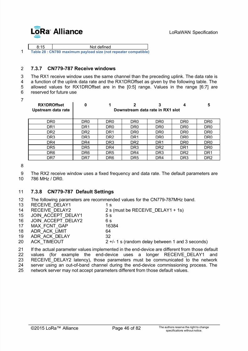
7/23/2019 LoRaWAN Specification 1R0
http://slidepdf.com/reader/full/lorawan-specification-1r0 46/82
LoRaWAN Specification
©2015 LoRa™ Alliance Page 46 of 82 The authors reserve the right to changespecifications without notice.
8:15 Not definedTable 28 : CN780 maximum payload size (not repeater compatible)1
7.3.7 CN779-787 Receive windows2
The RX1 receive window uses the same channel than the preceding uplink. The data rate is3a function of the uplink data rate and the RX1DROffset as given by the following table. The4allowed values for RX1DROffset are in the [0:5] range. Values in the range [6:7] are5reserved for future use6
7RX1DROffset 0 1 2 3 4 5
Upstream data rate Downstream data rate in RX1 slot
DR0 DR0 DR0 DR0 DR0 DR0 DR0DR1 DR1 DR0 DR0 DR0 DR0 DR0
DR2 DR2 DR1 DR0 DR0 DR0 DR0
DR3 DR3 DR2 DR1 DR0 DR0 DR0
DR4 DR4 DR3 DR2 DR1 DR0 DR0
DR5 DR5 DR4 DR3 DR2 DR1 DR0
DR6 DR6 DR5 DR4 DR3 DR2 DR1
DR7 DR7 DR6 DR5 DR4 DR3 DR2
8
The RX2 receive window uses a fixed frequency and data rate. The default parameters are9786 MHz / DR0.10
7.3.8 CN779-787 Default Settings11
The following parameters are recommended values for the CN779-787MHz band.12RECEIVE_DELAY1 1 s13RECEIVE_DELAY2 2 s (must be RECEIVE_DELAY1 + 1s)14JOIN_ACCEPT_DELAY1 5 s15JOIN_ACCEPT_DELAY2 6 s16MAX_FCNT_GAP 1638417 ADR_ACK_LIMIT 6418 ADR_ACK_DELAY 3219 ACK_TIMEOUT 2 +/- 1 s (random delay between 1 and 3 seconds)20
If the actual parameter values implemented in the end-device are different from those default21values (for example the end-device uses a longer RECEIVE_DELAY1 and22RECEIVE_DELAY2 latency), those parameters must be communicated to the network23server using an out-of-band channel during the end-device commissioning process. The24network server may not accept parameters different from those default values.25

7/23/2019 LoRaWAN Specification 1R0
http://slidepdf.com/reader/full/lorawan-specification-1r0 47/82
LoRaWAN Specification
©2015 LoRa™ Alliance Page 47 of 82 The authors reserve the right to changespecifications without notice.
1
7.4 EU 433MHz ISM Band2
7.4.1 EU433 Preamble Format3
The following synchronization words should be used :45
Modulation Sync word Preamble length
LORA 0x34 8 symbols
GFSK 0xC194C1 5 bytesTable 29: EU433 synch words6
7.4.2 EU433 ISM Band channel frequencies7
The LoRaWAN can be used in the ETSI 433-434 MHz band as long as the radio device8EIRP is less than 10 mW (or 10 dBm).9
The end-device transmit duty-cycle should be lower than 1%1.10
The LoRaWAN channels center frequency can be in the following range:11
Minimum frequency : 433.175 MHz12
Maximum frequency : 434.665 MHz13
EU433 end-devices should be capable of operating in the 433.05 to 434.79 MHz frequency14band and should feature a channel data structure to store the parameters of at least 1615channels. A channel data structure corresponds to a frequency and a set of data rates16usable on this frequency.17
The first three channels correspond to 433.175, 433.375 and 433.575 MHz with DR0 to DR518and must be implemented in every end-device. Those default channels cannot be modified19through the NewChannelReq command and guarantee a minimal common channel set20between end-devices and gateways of all networks. Other channels can be freely distributed21across the allowed frequency range on a network per network basis.22
The following table gives the list of frequencies that should be used by end-devices to23broadcast the JoinReq message. The JoinReq message transmit duty-cycle should never24exceed 0.1%25
26Modulation Bandwidth [kHz] Channel
Frequency[MHz]
FSKBitrate orLoRa DR / Bitrate
NbChannels
Dutycycle
LoRa125 433.175
433.375433.575
DR0 – DR5
/ 0.3-5kbps
3 <1%
Table 30: EU433 JoinReq Channel List27
1
The EN300220 ETSI standard limits to 10% the maximum transmit duty-cycle in the 433MHz ISMband. The LoRaWAN requires a 1% transmit duty-cycle lower than the legal limit to avoid networkcongestion.

7/23/2019 LoRaWAN Specification 1R0
http://slidepdf.com/reader/full/lorawan-specification-1r0 48/82
LoRaWAN Specification
©2015 LoRa™ Alliance Page 48 of 82 The authors reserve the right to changespecifications without notice.
7.4.3 EU433 Data Rate and End-point Output Power encoding1
The following encoding is used for Data Rate (DR) and End-point Output Power (TXPower)2
in the EU433 band:3 DataRate Configuration Indicative physicalbit rate [bit/s]
TXPower Configuration
0 LoRa: SF12 / 125 kHz 250 0 10 dBm
1 LoRa: SF11 / 125 kHz 440 1 7 dBm
2 LoRa: SF10 / 125 kHz 980 2 4 dBm
3 LoRa: SF9 / 125 kHz 1760 3 1 dBm
4 LoRa: SF8 / 125 kHz 3125 4 -2 dBm
5 LoRa: SF7 / 125 kHz 5470 5 -5 dBm
6 LoRa: SF7 / 250 kHz 11000 6..15 RFU
7 FSK: 50 kbps 50000
8..15 RFU
Table 31: Data rate and TX power table4
7.4.4 EU433 JoinAccept CFList56
The EU433 ISM band LoRaWAN implements an optional channel frequency list (CFlist) of716 octets in the JoinAccept message.8
In this case the CFList is a list of five channel frequencies for the channels four to eight9whereby each frequency is encoded as a 24 bits unsigned integer (three octets). All these10channels are usable for DR0 to DR5 125 kHz LoRa modulation. The list of frequencies is11followed by a single RFU octet for a total of 16 octets.12
13Size
(bytes)3 3 3 3 3 1
CFList Freq Ch4 Freq Ch5 Freq Ch6 Freq CN7 Freq Ch8 RFU
The actual channel frequency in Hz is 100 x frequency whereby values representing14frequencies below 100 Mhz are reserved for future use. This allows setting the frequency of15a channel anywhere between 100 MHz to 1.67 GHz in 100 Hz steps. Unused channels have16a frequency value of 0. The CFList is optional and its presence can be detected by the17length of the join-accept message. If present, the CFList replaces all the previous channels18stored in the end-device apart from the three default channels as defined in Chapter 6.19
The newly defined channels are immediately enabled and usable by the end-device for20 communication.21
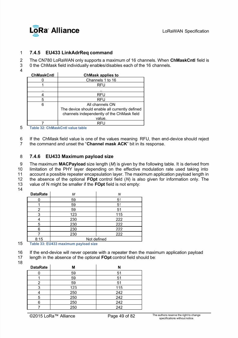
7/23/2019 LoRaWAN Specification 1R0
http://slidepdf.com/reader/full/lorawan-specification-1r0 49/82
LoRaWAN Specification
©2015 LoRa™ Alliance Page 49 of 82 The authors reserve the right to changespecifications without notice.
7.4.5 EU433 LinkAdrReq command1
The CN780 LoRaWAN only supports a maximum of 16 channels. When ChMaskCntl field is20 the ChMask field individually enables/disables each of the 16 channels.3
4ChMaskCntl ChMask applies to
0 Channels 1 to 16
1 RFU
.. ..
4 RFU
5 RFU
6 All channels ONThe device should enable all currently definedchannels independently of the ChMask field
value.7 RFU
Table 32: ChMaskCntl value table5
If the ChMask field value is one of the values meaning RFU, then end-device should reject6the command and unset the ―Channel mask ACK‖ bit in its response. 7
7.4.6 EU433 Maximum payload size8
The maximum MACPayload size length (M ) is given by the following table. It is derived from9limitation of the PHY layer depending on the effective modulation rate used taking into10account a possible repeater encapsulation layer. The maximum application payload length in11
the absence of the optional FOpt control field (N ) is also given for information only. The12value of N might be smaller if the FOpt field is not empty:13
14DataRate M N
0 59 51
1 59 51
2 59 51
3 123 115
4 230 222
5 230 222
6 230 222
7 230 222
8:15 Not definedTable 33: EU433 maximum payload size15
If the end-device will never operate with a repeater then the maximum application payload16length in the absence of the optional FOpt control field should be:17
18DataRate M N
0 59 51
1 59 51
2 59 51
3 123 115
4 250 242
5 250 2426 250 242
7 250 242

7/23/2019 LoRaWAN Specification 1R0
http://slidepdf.com/reader/full/lorawan-specification-1r0 50/82
LoRaWAN Specification
©2015 LoRa™ Alliance Page 50 of 82 The authors reserve the right to changespecifications without notice.
8:15 Not definedTable 34 : EU433 maximum payload size (not repeater compatible)1
2
7.4.7 EU433 Receive windows3
The RX1 receive window uses the same channel than the preceding uplink. The data rate is4a function of the uplink data rate and the RX1DROffset as given by the following table. The5allowed values for RX1DROffset are in the [0:5] range. Values in the range [6:7] are6reserved for future use.7
8RX1DROffset 0 1 2 3 4 5
Upstream data rate Downstream data rate in RX1 slot
DR0 DR0 DR0 DR0 DR0 DR0 DR0
DR1 DR1 DR0 DR0 DR0 DR0 DR0
DR2 DR2 DR1 DR0 DR0 DR0 DR0
DR3 DR3 DR2 DR1 DR0 DR0 DR0
DR4 DR4 DR3 DR2 DR1 DR0 DR0
DR5 DR5 DR4 DR3 DR2 DR1 DR0
DR6 DR6 DR5 DR4 DR3 DR2 DR1
DR7 DR7 DR6 DR5 DR4 DR3 DR2
9
10
11
The RX2 receive window uses a fixed frequency and data rate. The default parameters are12434.665MHz / DR0 (SF12 , 125kHz)13
7.4.8 EU433 Default Settings14
The following parameters are recommended values for the EU863-870Mhz band.15RECEIVE_DELAY1 1 s16RECEIVE_DELAY2 2 s (must be RECEIVE_DELAY1 + 1s)17JOIN_ACCEPT_DELAY1 5 s18JOIN_ACCEPT_DELAY2 6 s19
MAX_FCNT_GAP 1638420 ADR_ACK_LIMIT 6421 ADR_ACK_DELAY 3222 ACK_TIMEOUT 2 +/- 1 s (random delay between 1 and 3 seconds)23
24If the actual parameter values implemented in the end-device are different from those default25values (for example the end-device uses a longer RECEIVE_DELAY1 & 2 latency) , those26parameters must be communicated to the network server using an out-of-band channel27during the end-device commissioning process. The network server may not accept28parameters different from those default values.29

7/23/2019 LoRaWAN Specification 1R0
http://slidepdf.com/reader/full/lorawan-specification-1r0 51/82
LoRaWAN Specification
©2015 LoRa™ Alliance Page 51 of 82 The authors reserve the right to changespecifications without notice.
CLASS B – BEACON 1

7/23/2019 LoRaWAN Specification 1R0
http://slidepdf.com/reader/full/lorawan-specification-1r0 52/82
LoRaWAN Specification
©2015 LoRa™ Alliance Page 52 of 82 The authors reserve the right to changespecifications without notice.
8 Introduction to Class B1
This section describes the LoRaWAN Class B layer which is optimized for battery-powered2end-devices that may be either mobile or mounted at a fixed location.3
End-devices should implement Class B operation when there is a requirement to open4receive windows at fixed time intervals for the purpose of enabling server initiated downlink5messages.6
LoRaWAN Class B option adds a synchronized reception window on the end-device.7
One of the limitations of LoRaWAN Class A is the Aloha method of sending data from the8end-device; it does not allow for a known reaction time when the customer application or the9server wants to address the end-device. The purpose of Class B is to have an end-device10available for reception on a predictable time, in addition to the reception windows that11follows the random uplink transmission from the end-device of Class A. Class B is achieved12
by having the gateway sending a beacon on a regular basis to synchronize the all the end-13devices in the network so that the end-device can opening a short extra reception window14(called ―ping slot‖) at a predictable time during a periodic time slot. 15
Note: The decision to switch from Class A to Class B comes from the16application layer of the end-device. If this class A to Class B switch17needs to be controlled from the network side, the customer application18must use one of the end-device‘s Class A uplinks to send back a19downlink to the application layer, and it needs the application layer on20the end-device to recognize this request – this process is not managed21at the LoRaWAN level.22
7/23/2019 LoRaWAN Specification 1R0
http://slidepdf.com/reader/full/lorawan-specification-1r0 53/82
LoRaWAN Specification
©2015 LoRa™ Alliance Page 53 of 82 The authors reserve the right to changespecifications without notice.
9 Principle of synchronous network initiated downlink (Class-B1
option)2
For a network to support end-devices of Class B, all gateways must synchronously3broadcast a beacon providing a timing reference to the end-devices. Based on this timing4reference the end-devices can periodically open receive windows, hereafter called ―ping5slots‖, which can be used by the network infrastructure to initiate a downlink communication.6 A network initiated downlink using one of these ping slots is called a ―ping‖. The gateway7chosen to initiate this downlink communication is selected by the network server based on8the signal quality indicators of the last uplink of the end-device. For this reason, if an end-9device moves and detects a change in the identity advertised in the received beacon, it must10send an uplink to the network server so that the server can update the downlink routing path11database.12
All end-devices start and join the network as end-devices of Class A. The end-device13application can then decide to switch to Class B. This is done through the following process:14
The end-device application requests the LoRaWAN layer to switch to Class B mode.15The LoRaWAN layer in the end-device searches for a beacon and returns either a16BEACON_LOCKED service primitive to the application if a network beacon was17found and locked or a BEACON_NOT_FOUND service primitive. To accelerate the18beacon discovery the LoRaWAN layer may use the ―BeaconTimingReq‖ message19described later.20
Based on the beacon strength and the battery life constraints, the end-device21application selects a ping slot data rate and periodicity, this is then requested them22from the end-device LoRaWAN layer.23
Once in Class B mode, the MAC layer sets to 1 the Class B bit of the FCTRL field of24every uplink frame transmitted. This bit signals to the server that the device has25switched to Class B. The MAC layer will autonomously schedule a reception slot for26each beacon and each ping slot. When the beacon reception is successful the end-27device LoRaWAN layer forwards the beacon content to the application together with28the measured radio signal strength. The end-device LoRaWAN layer takes into29account the maximum possible clock drift in the scheduling of the beacon reception30slot and ping slots. When a downlink is successfully demodulated during a ping slot,31it is processed similarly to a downlink as described in the LoRaWAN Class A32specification.33
A mobile end-device must periodically inform the network server of its location to34
update the downlink route. This is done by transmitting a normal (possibly empty)35―unconfirmed‖ or ―confirmed‖ uplink. The end-device LoRaWAN layer will36appropriately set the Class B bit to 1. Optimally this can be done more efficiently if37the application detects that the node is moving by analyzing the beacon content. In38that case the end-device must apply a random delay (as defined in Section 15.539between the beacon reception and the uplink transmission to avoid systematic uplink40collisions.41
If no beacon has been received for a given period (as defined in Section 12.2), the42synchronization with the network is lost. The MAC layer must inform the application43layer that it has switched back to Class A. As a consequence the end-device44LoRaWAN layer stops setting the Class B bit in all uplinks and this informs the45
network server that the end-device is no longer in Class B mode. The end-device46application can try to switch back to Class B periodically. This will restart this process47starting with a beacon search.48
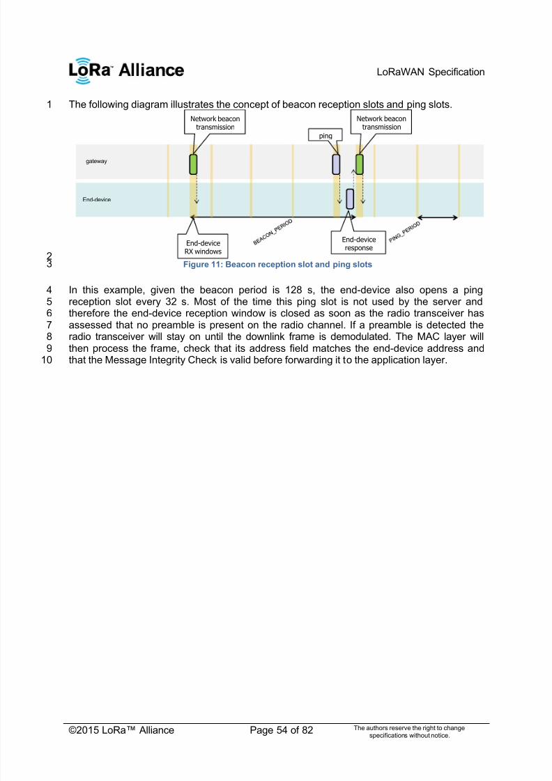
7/23/2019 LoRaWAN Specification 1R0
http://slidepdf.com/reader/full/lorawan-specification-1r0 54/82
LoRaWAN Specification
©2015 LoRa™ Alliance Page 54 of 82 The authors reserve the right to changespecifications without notice.
The following diagram illustrates the concept of beacon reception slots and ping slots.1
2Figure 11: Beacon reception slot and ping slots3
In this example, given the beacon period is 128 s, the end-device also opens a ping4reception slot every 32 s. Most of the time this ping slot is not used by the server and5therefore the end-device reception window is closed as soon as the radio transceiver has6assessed that no preamble is present on the radio channel. If a preamble is detected the7radio transceiver will stay on until the downlink frame is demodulated. The MAC layer will8then process the frame, check that its address field matches the end-device address and9that the Message Integrity Check is valid before forwarding it to the application layer.10
gateway
End-device
End-deviceRX windows
Network beacontransmission
Network beacontransmission
ping
End-deviceresponse

7/23/2019 LoRaWAN Specification 1R0
http://slidepdf.com/reader/full/lorawan-specification-1r0 55/82
LoRaWAN Specification
©2015 LoRa™ Alliance Page 55 of 82 The authors reserve the right to changespecifications without notice.
10 Uplink frame in Class B mode1
The uplink frames in Class B mode are same as the Class A uplinks with the exception of2
the RFU bit in the FCtrl field in the Frame header. In the Class A uplink this bit is unused3(RFU). This bit is used for Class B uplinks.4
5
Bit# 7 6 5 4 3..0
FCtrl ADR ADRACKReq ACK Class B FOptsLen
6The Class B bit set to 1 in an uplink signals the network server that the device as switched to7Class B mode and is now ready to receive scheduled downlink pings.8
9The signification of the FPending bit for downlink is unaltered and still signals that one or10more downlink frames are queued for this device in the server and that the device should11
keep is receiver on as described in the Class A specification.1213
7/23/2019 LoRaWAN Specification 1R0
http://slidepdf.com/reader/full/lorawan-specification-1r0 56/82
LoRaWAN Specification
©2015 LoRa™ Alliance Page 56 of 82 The authors reserve the right to changespecifications without notice.
11 Downlink Ping frame format (Class B option)1
11.1 Physical frame format2
A downlink Ping uses the same format as a Class A downlink frame but might follow a3different channel frequency plan.4
11.2 Unicast & Multicast MAC messages5
Messages can be ―unicast‖ or ―multicast‖. Unicast messages are sent to a single end-device6and multicast messages are sent to multiple end-devices. All devices of a multicast group7must share the same multicast address and associated encryption keys. The LoRaWAN8Class B specification does not specify means to remotely setup such a multicast group or9securely distribute the required multicast key material. This must either be performed during10
the node personalization or through the application layer.11
11.2.1 Unicast MAC message format12
The MAC payload of a unicast downlink Ping uses the format defined in the Class A13specification. It is processed by the end-device in exactly the same way. The same frame14counter is used and incremented whether the downlink uses a Class B ping slot or a Class A15―piggy-back‖ slot. 16
11.2.2 Multicast MAC message format17
The Multicast frames share most of the unicast frame format with a few exceptions:18
They are not allowed to carry MAC commands, neither in the FOpt field, nor in the19payload on port 0 because a multicast downlink does not have the same20authentication robustness as a unicast frame.21
The ACK and ADRACKReq bits must be zero. The MType field must carry the value22for Unconfirmed Data Down.23
The FPending bit indicates there is more multicast data to be sent. If it is set the24next multicast receive slot will carry a data frame. If it is not set the next slot may or25may not carry data. This bit can be used by end-devices to evaluate priorities for26conflicting reception slots.27
28

7/23/2019 LoRaWAN Specification 1R0
http://slidepdf.com/reader/full/lorawan-specification-1r0 57/82
LoRaWAN Specification
©2015 LoRa™ Alliance Page 57 of 82 The authors reserve the right to changespecifications without notice.
12 Beacon acquisition and tracking1
Before switching from Class A to Class B, the end-device must first receive one of the2network beacons to align his internal timing reference with the network.3
Once in Class B, the end-device must periodically search and receive a network beacon to4cancel any drift of its internal clock time base, relative to the network timing.5
A Class B device may be temporarily unable to receive beacons (out of range from the6network gateways, presence of interference, ..). In this event, the end-device has to7gradually widen its beacon and ping slots reception windows to take into account a possible8drift of its internal clock.9
Note: For example, a device which internal clock is defined with a +/-1010ppm precision may drift by +/-1.3mSec every beacon period.11
12.1 Minimal beacon-less operation time12
In the event of beacon loss, a device shall be capable of maintaining Class B operation for 213hours (120 minutes) after it received the last beacon. This temporary Class B operation14without beacon is called ―beacon-less‖ operation. It relies on the end-device‘s own clock to15keep timing.16
During beacon-less operation, unicast, multicast and beacon reception slots must all be17progressively expanded to accommodate the end-device‘s possible clock drift.18
19
20Figure 12 : beacon-less temporary operation21
12.2 Extension of beacon-less operation upon reception22
During this 120 minutes time interval the reception of any beacon directed to the end-device,23should extend the Class B beacon-less operation further by another 120 minutes as it allows24to correct any timing drift and reset the receive slots duration.25
12.3 Minimizing timing drift26
The end-devices may use the beacon‘s (when available) precise periodicity to calibrate their27internal clock and therefore reduce the initial clock frequency imprecision. As the timing28oscillator ‘s exhibit a predictable temperature frequency shift, the use of a temperature29sensor could enable further minimization of the timing drift.30
End-device
End-devicereceives the
beacon
Beacon receptionwindow
End-devicetemporarily stopreceiving beacon
End-device receives abeacon and resets the
reception window length
Reception windowenlarges to
accommodate clock drift

7/23/2019 LoRaWAN Specification 1R0
http://slidepdf.com/reader/full/lorawan-specification-1r0 58/82
LoRaWAN Specification
©2015 LoRa™ Alliance Page 58 of 82 The authors reserve the right to changespecifications without notice.
13 Class B Downlink slot timing1
13.1 Definitions2
To operate successfully in Class B the end-device must open reception slots at precise3instants relative to the infrastructure beacon. This section defines the required timing.4
The interval between the start of two successive beacons is called the beacon period. The5beacon frame transmission is aligned with the beginning of the BEACON_RESERVED6interval. Each beacon is preceded by a guard time interval where no ping slot can be placed.7The length of the guard interval corresponds to the time on air of the longest allowed frame.8This is to insure that a downlink initiated during a ping slot just before the guard time will9always have time to complete without colliding with the beacon transmission. The usable10time interval for ping slot therefore spans from the end of the beacon reserved time interval11
to the beginning of the next beacon guard interval.12
13Figure 13: Beacon timing14
Beacon_period 128 s
Beacon_reserved 2.120 s
Beacon_guard 3.000 s
Beacon-window 122.880 sTable 35: Beacon timing15
The beacon frame time on air is actually much shorter than the beacon reserved time16interval to allow appending network management broadcast frames in the future.17
The beacon window interval is divided into 212 = 4096 ping slots of 30 ms each numbered18from 0 to 4095.19
An end-device using the slot number N must turn on its receiver exactly Ton seconds after20the start of the beacon where:21
Ton = beacon _ reserved + N * 30 ms22
N is called the slot index. 23
The latest ping slot starts at beacon _ reserved + 4095 * 30 ms = 124 970 ms after the24beacon start or 3030 ms before the beginning of the next beacon.25
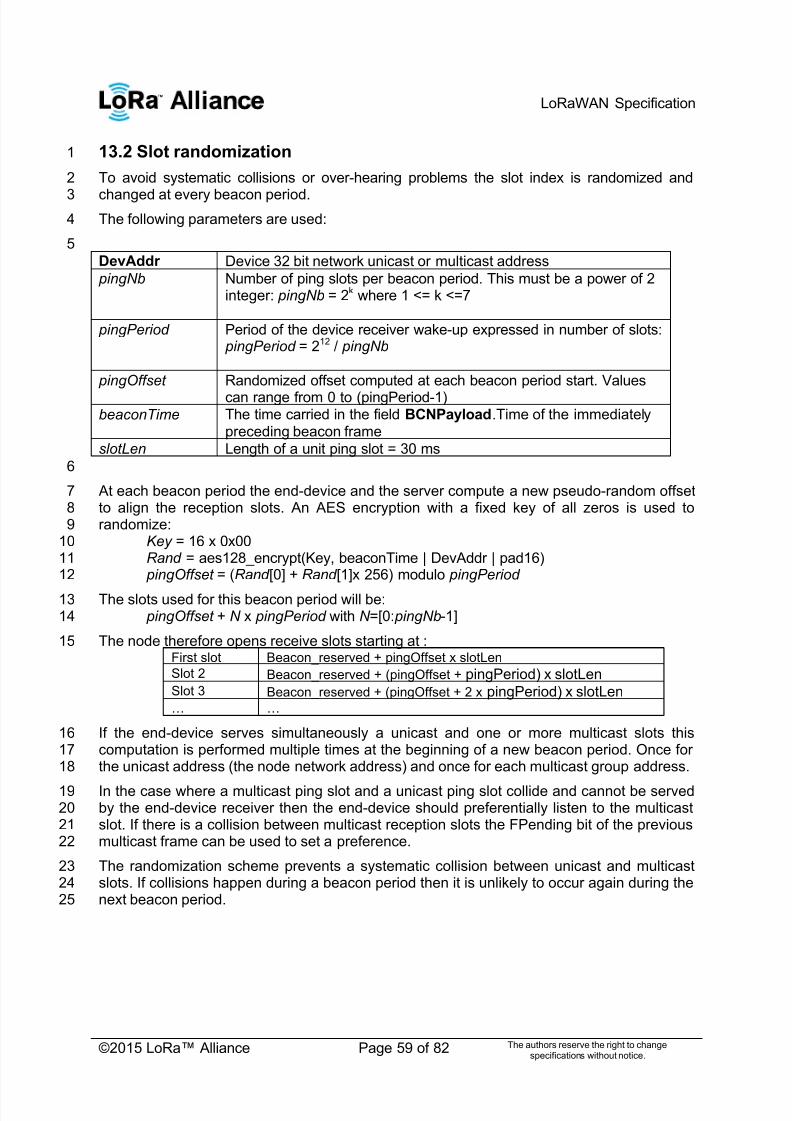
7/23/2019 LoRaWAN Specification 1R0
http://slidepdf.com/reader/full/lorawan-specification-1r0 59/82
LoRaWAN Specification
©2015 LoRa™ Alliance Page 59 of 82 The authors reserve the right to changespecifications without notice.
13.2 Slot randomization1
To avoid systematic collisions or over-hearing problems the slot index is randomized and2
changed at every beacon period.3The following parameters are used:4
5
DevAddr Device 32 bit network unicast or multicast address
pingNb Number of ping slots per beacon period. This must be a power of 2integer: pingNb = 2k where 1 <= k <=7
pingPeriod Period of the device receiver wake-up expressed in number of slots: pingPeriod = 212 / pingNb
pingOffset Randomized offset computed at each beacon period start. Values
can range from 0 to (pingPeriod-1)beaconTime The time carried in the field BCNPayload.Time of the immediately
preceding beacon frame
slotLen Length of a unit ping slot = 30 ms
6
At each beacon period the end-device and the server compute a new pseudo-random offset7to align the reception slots. An AES encryption with a fixed key of all zeros is used to8randomize:9
Key = 16 x 0x0010Rand = aes128_encrypt(Key, beaconTime | DevAddr | pad16)11 pingOffset = (Rand [0] + Rand [1]x 256) modulo pingPeriod 12
The slots used for this beacon period will be:13 pingOffset + N x pingPeriod with N =[0: pingNb-1]14
The node therefore opens receive slots starting at :15First slot Beacon_reserved + pingOffset x slotLen
Slot 2 Beacon_reserved + (pingOffset + pingPeriod) x slotLen
Slot 3 Beacon_reserved + (pingOffset + 2 x pingPeriod) x slotLen
… …
If the end-device serves simultaneously a unicast and one or more multicast slots this16computation is performed multiple times at the beginning of a new beacon period. Once for17the unicast address (the node network address) and once for each multicast group address.18
In the case where a multicast ping slot and a unicast ping slot collide and cannot be served19by the end-device receiver then the end-device should preferentially listen to the multicast20slot. If there is a collision between multicast reception slots the FPending bit of the previous21multicast frame can be used to set a preference.22
The randomization scheme prevents a systematic collision between unicast and multicast23slots. If collisions happen during a beacon period then it is unlikely to occur again during the24next beacon period.25

7/23/2019 LoRaWAN Specification 1R0
http://slidepdf.com/reader/full/lorawan-specification-1r0 60/82
LoRaWAN Specification
©2015 LoRa™ Alliance Page 60 of 82 The authors reserve the right to changespecifications without notice.
14 Class B MAC commands1
All commands described in the Class A specification shall be implemented in Class B2devices. The Class B specification adds the following MAC commands.3
4CID Command Transmitted by Short Description
End-device
Gateway
0x10 PingSlotInfoReq x Used by the end-device to communicatethe ping unicast slot data rate andperiodicity to the network server
0x10 PingSlot InfoAns x Used by the network to acknowledge aPingInfoSlotReq command
0x11 PingSlotChannelReq x Used by the network server to set theunicast ping channel of an end-device
0x11 PingSlotFreqAns x Used by the end-device to acknowledge aPingSlotChannelReq command
0x12 BeaconTimingReq x Used by end-device to request nextbeacon timing & channel to network
0x12 BeaconTimingAns x Used by network to answer aBeaconTimingReq uplink
0x13 BeaconFreqReq x Command used by the network server tomodify the frequency at which the end-device expects to receive beaconbroadcast
0x13 BeaconFreqAns x Used by the end-device to acknowledge aBeaconFreqReq command
14.1 PingSlotInfoReq5
With the PingSlotInfoReq command an end-device informs the server of its unicast ping6slot periodicity and expected data rate. This command must only be used to inform the7server of the parameters of a UNICAST ping slot. A multicast slot is entirely defined by the8application and should not use this command.9
10Size (bytes) 1
PingSlotInfoReq Payload Periodicity & data rate
11
Bit# 7 [6:4] [3:0]
Periodicity & data rate RFU Periodicity Data rate
The Periodicity subfield is an unsigned 3 bits integer encoding the ping slot period currently12used by the end-device using the following equation.13
in seconds14
Periodicity = 0 means that the end-device opens a ping slot every second15
Periodicity = 7 , every 128 seconds which is the maximum ping period supported by16the LoRaWAN Class B specification.17
The Data rate subfield encodes the data rate at which the end-point expects any ping. This18
uses the same encoding scheme that the LinkAdrReq command described in the Class A19specification.20

7/23/2019 LoRaWAN Specification 1R0
http://slidepdf.com/reader/full/lorawan-specification-1r0 61/82
LoRaWAN Specification
©2015 LoRa™ Alliance Page 61 of 82 The authors reserve the right to changespecifications without notice.
The server needs to be aware of the end-device ping slot periodicity or expected data rate1else Class B downlinks will not happen successfully. For that purpose the PingSlotInfoReq 2MAC command must be acknowledged with a PingSlotInfoAns before the device can3
switch from class A to Class B. To change its ping slot scheduling or data rate a device4should first revert to Class A , send the new parameters through a PingSlotInfoReq 5command and get an acknowledge from the server through a PinSlotInfoAns . It can then6switch back to Class B with the new parameters.7
This command can be concatenated with any other MAC command in the FHDRFOpt field8as described in the Class A specification frame format.9
14.2 BeaconFreqReq10
This command is sent by the server to the end-device to modify the frequency on which this11end-device expects the beacon.12
13Octets 3
PingSlotChannelReqPayload
Frequency
14
The Frequency coding is identical to the NewChannelReq MAC command defined in the15Class A.16
Frequency is a 24bits unsigned integer. The actual beacon channel frequency in Hz is 10017x frequ. This allows defining the beacon channel anywhere between 100 MHz to 1.67 GHz18by 100 Hz step. The end-device has to check that the frequency is actually allowed by its19radio hardware and return an error otherwise.20
A valid non-zero Frequency will force the device to listen to the beacon on a fixed frequency21channel even if the default behavior specifies a frequency hopping beacon (i.e US ISM22band).23
A value of 0 instructs the end-device to use the default beacon frequency plan as defined in24the ―Beacon physical layer ‖ section. Where applicable the device resumes frequency25hopping beacon search.26
14.3 PingSlotChannelReq27
This command is sent by the server to the end-device to modify the frequency on which this28
end-device expects the downlink pings.2930
Octets 3 1
PingSlotChannelReqPayload
Frequency DrRange
31
The Frequency coding is identical to the NewChannelReq MAC command defined in the32Class A.33
Frequency is a 24bits unsigned integer. The actual ping channel frequency in Hz is 100 x34frequ. This allows defining the ping channel anywhere between 100MHz to 1.67GHz by35100Hz step. The end-device has to check that the frequency is actually allowed by its radio36
hardware and return an error otherwise.37
A value of 0 instructs the end-device to use the default frequency plan.38

7/23/2019 LoRaWAN Specification 1R0
http://slidepdf.com/reader/full/lorawan-specification-1r0 62/82
LoRaWAN Specification
©2015 LoRa™ Alliance Page 62 of 82 The authors reserve the right to changespecifications without notice.
DrRange is the data rate range allowed on this channel. This byte is split in two 4-bit1indexes.2
3
Bits 7:4 3:0
DrRange Max data rate Min data rate
4
Following the convention defined in the ―Physical layer‖ section of the Class A specification,5the ―Min data rate‖ subfield designates the lowest data rate allowed on this channel. For6example 0 designates DR0 / 125 kHz in the EU physical layer. Similarly ―Max data rate‖7designates the highest data rate. For example in the EU spec, DrRange = 0x77 means that8only 50 kbps GFSK is allowed on a channel and DrRange = 0x50 means that DR0 / 125 kHz9to DR5 / 125 kHz are supported.10
Upon reception of this command the end-device answers with a PingSlotFreqAns 11message. The MAC payload of this message contains the following information:12
13Size (bytes) 1
pingSlotFreqAns Payload Status
The Status bits have the following meaning:14
Bits 7:2 1 0
StatusRFU Data rate range
okChannel
frequency ok
15Bit = 0 Bit = 1
Data rate range ok The designated data raterange exceeds the onescurrently defined for this enddevice, the previous range iskept
The data rate range iscompatible with thepossibilities of the end device
Channel frequency ok The device cannot use thisfrequency, the previous pingfrequency is kept
The device is able to use thisfrequency.
14.4 BeaconTimingReq16
This command is sent by the end-device to request the next beacon timing and channel.17This MAC command has no payload. The BeaconTimingReq & BeaconTimingAns 18mechanism is only meant to accelerate the initial beacon search to lower the end-device19energy requirement.20
The network may answer only a limited number of requests per a given time period. An end-21device must not expect that BeaconTimingReq is answered immediately with a22BeaconTimingAns . Class A end-devices wanting to switch to Class B should not transmit23more than one BeaconTimingReq per hour.24
End-devices requiring a fast beacon lock must implement an autonomous beacon finding25algorithm.26

7/23/2019 LoRaWAN Specification 1R0
http://slidepdf.com/reader/full/lorawan-specification-1r0 63/82
LoRaWAN Specification
©2015 LoRa™ Alliance Page 63 of 82 The authors reserve the right to changespecifications without notice.
14.5 BeaconTimingAns1
This command is sent by the network to answer a BeaconInfoReq request.2Size (bytes) 2 1
BeaconInfoReqPayload Delay Channel
The ―Delay‖ field is a 16bits unsigned integer. If the remaining time between the end of the3current downlink frame and the start of the next beacon frame is noted RTime then:4
30 ms x ( Delay +1) > RTime >= 30 ms x Delay 5
In networks where the beacon uses alternatively several channels, the ―Channel‖ field is the6index of the beaconing channel on which the next beacon will be broadcasted. For networks7where the beacon broadcast frequency is fixed then this field content is 0.8
9

7/23/2019 LoRaWAN Specification 1R0
http://slidepdf.com/reader/full/lorawan-specification-1r0 64/82
LoRaWAN Specification
©2015 LoRa™ Alliance Page 64 of 82 The authors reserve the right to changespecifications without notice.
15 Beaconing (Class B option)1
15.1 Beacon physical layer2
Besides relaying messages between end-devices and network servers, all gateways3participate in providing a time-synchronization mechanisms by sending beacons at regular4fixed intervals configurable per network (BEACON_INTERVAL). All beacons are transmitted5in radio packet implicit mode, that is, without a LoRa physical header and with no CRC being6appended by the radio.7
8PHY Preamble BCNPayload
The beacon Preamble begins with (a longer than default) 10 unmodulated symbols. This9allows end-devices to implement a low power duty-cycled beacon search.10
The beacon frame length is tightly coupled to the operation of the radio Physical layer.11Therefore the actual frame length might change from one region implementation to another.12The changing fields are highlighted in Bold in the following sections.13
15.1.1 EU 863-870MHz ISM Band14
The beacons are transmitted using the following settings15
DR 3 Corresponds to SF9 spreading factor with125 kHz BW
CR 1 Coding rate = 4/5
frequency 869.525 MHz This is the recommended frequency allowing
+27 dBm EIRP. Network operators may usea different frequency as long as ETSI
compliance is achieved
The beacon frame content is:16Size (bytes) 3 4 1 7 2
BCNPayload NetID Time CRC GwSpecific CRC
15.1.2 US 902-928MHz ISM Band17
The beacons are transmitted using the following settings:18
DR 10 Corresponds to SF10 spreading factor
with 500kHz bwCR 1 Coding rate = 4/5
frequencies 923.3 to 927.5MHzwith 600kHz steps
Beaconing is performed on the samechannel that normal downstream traffic as
defined in the Class A specification
The downstream channel used for a given beacon is:19
Channel = * + 20
whereby beacon_time is the integer value of the 4 bytes ―Time‖ field of the beacon21frame22
whereby beacon_period is the periodicity of beacons , 128 seconds23
whereby floor(x) designates rounding to the integer immediately inferior to x2425
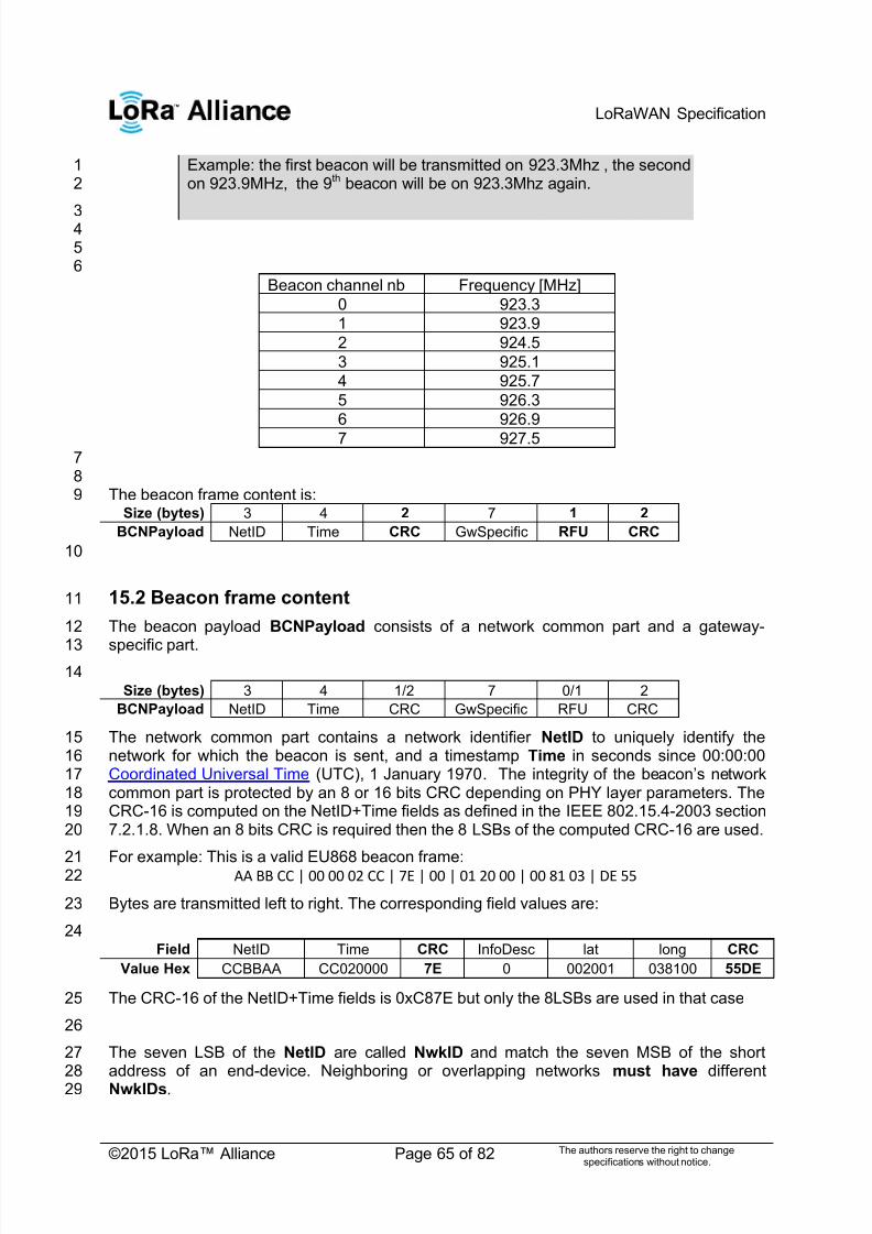
7/23/2019 LoRaWAN Specification 1R0
http://slidepdf.com/reader/full/lorawan-specification-1r0 65/82
LoRaWAN Specification
©2015 LoRa™ Alliance Page 65 of 82 The authors reserve the right to changespecifications without notice.
Example: the first beacon will be transmitted on 923.3Mhz , the second1on 923.9MHz, the 9th beacon will be on 923.3Mhz again.2
3456
Beacon channel nb Frequency [MHz]
0 923.3
1 923.9
2 924.5
3 925.1
4 925.7
5 926.3
6 926.9
7 927.578
The beacon frame content is:9Size (bytes) 3 4 2 7 1 2
BCNPayload NetID Time CRC GwSpecific RFU CRC
10
15.2 Beacon frame content11
The beacon payload BCNPayload consists of a network common part and a gateway-12
specific part.1314
Size (bytes) 3 4 1/2 7 0/1 2
BCNPayload NetID Time CRC GwSpecific RFU CRC
The network common part contains a network identifier NetID to uniquely identify the15network for which the beacon is sent, and a timestamp Time in seconds since 00:00:0016Coordinated Universal Time (UTC), 1 January 1970. The integrity of the beacon‘s network17common part is protected by an 8 or 16 bits CRC depending on PHY layer parameters. The18CRC-16 is computed on the NetID+Time fields as defined in the IEEE 802.15.4-2003 section197.2.1.8. When an 8 bits CRC is required then the 8 LSBs of the computed CRC-16 are used.20
For example: This is a valid EU868 beacon frame:21AA BB CC | 00 00 02 CC | 7E | 00 | 01 20 00 | 00 81 03 | DE 5522
Bytes are transmitted left to right. The corresponding field values are:23
24Field NetID Time CRC InfoDesc lat long CRC
Value Hex CCBBAA CC020000 7E 0 002001 038100 55DE
The CRC-16 of the NetID+Time fields is 0xC87E but only the 8LSBs are used in that case25
26
The seven LSB of the NetID are called NwkID and match the seven MSB of the short27address of an end-device. Neighboring or overlapping networks must have different28NwkIDs.29

7/23/2019 LoRaWAN Specification 1R0
http://slidepdf.com/reader/full/lorawan-specification-1r0 66/82
LoRaWAN Specification
©2015 LoRa™ Alliance Page 66 of 82 The authors reserve the right to changespecifications without notice.
The gateway specific part provides additional information regarding the gateway sending a1beacon and therefore may differ for each gateway. The RFU field when applicable (region2specific) should be equal to 0. The optional part is protected by a CRC-16 computed on the3
GwSpecific+RFU fields. The CRC-16 definition is the same as for the mandatory part.4
For example: This is a valid US900 beacon:5Field NetID Time CRC InfoDesc lat long RFU CRC
Value Hex CCBBAA CC020000 C87E 0 002001 038100 00 D450
Over the air the bytes are sent in the following order:6AA BB CC | 00 00 02 CC | 7E C8 | 00 | 01 20 00 | 00 81 03 |00 | 50 D47
Listening and synchronizing to the network common part is sufficient to operate a stationary8end-device in Class B mode. A mobile end-device should also demodulate the gateway9specific part of the beacon to be able to signal to the network server whenever he is moving10from one cell to another.11
Note: As mentioned before, all gateways send their beacon at exactly12the same point in time (i.e., time-synchronously) so that for network13common part there are no visible on-air collisions for a listening end-14device even if the end-device simultaneously receives beacons from15several gateways. With respect to the gateway specific part, collision16occurs but an end-device within the proximity of more than one17gateway will still be able to decode the strongest beacon with high18probability.19
15.3 Beacon GwSpecific field format20
The content of the GwSpecific field is as follow:21Size (bytes) 1 6
GwSpecific InfoDesc Info
The information descriptor InfoDesc describes how the information field Info shall be22interpreted.23
24InfoDesc Meaning
0 GPS coordinate of the gateway firstantenna
1 GPS coordinate of the gateway secondantenna
2 GPS coordinate of the gateway thirdantenna
3:127 RFU
128:255 Reserved for custom network specificbroadcasts
For a single omnidirectional antenna gateway the InfoDesc value is 0 when broadcasting25GPS coordinates. For a site featuring 3 sectored antennas for example, the first antenna26broadcasts the beacon with InfoDesc equals 0, the second antenna with InfoDesc field27equals 1, etc … 28
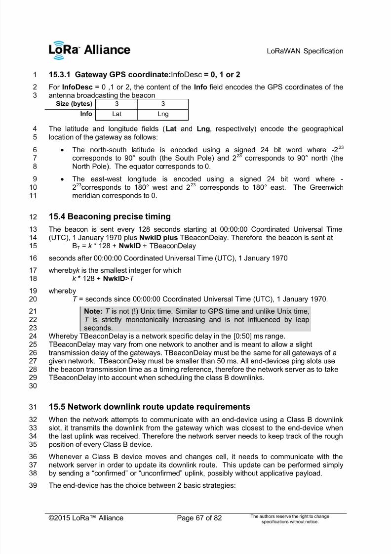
7/23/2019 LoRaWAN Specification 1R0
http://slidepdf.com/reader/full/lorawan-specification-1r0 67/82
LoRaWAN Specification
©2015 LoRa™ Alliance Page 67 of 82 The authors reserve the right to changespecifications without notice.
15.3.1 Gateway GPS coordinate:InfoDesc = 0, 1 or 21
For InfoDesc = 0 ,1 or 2, the content of the Info field encodes the GPS coordinates of the2
antenna broadcasting the beacon3Size (bytes) 3 3
Info Lat Lng
The latitude and longitude fields (Lat and Lng, respectively) encode the geographical4location of the gateway as follows:5
The north-south latitude is encoded using a signed 24 bit word where -2236corresponds to 90° south (the South Pole) and 223 corresponds to 90° north (the7North Pole). The equator corresponds to 0.8
The east-west longitude is encoded using a signed 24 bit word where -9223corresponds to 180° west and 223 corresponds to 180° east. The Greenwich10
meridian corresponds to 0.11
15.4 Beaconing precise timing12
The beacon is sent every 128 seconds starting at 00:00:00 Coordinated Universal Time13(UTC), 1 January 1970 plus NwkID plus TBeaconDelay. Therefore the beacon is sent at14
BT = k * 128 + NwkID + TBeaconDelay15
seconds after 00:00:00 Coordinated Universal Time (UTC), 1 January 197016
wherebyk is the smallest integer for which17k * 128 + NwkID>T 18
whereby19T = seconds since 00:00:00 Coordinated Universal Time (UTC), 1 January 1970.20
Note: T is not (!) Unix time. Similar to GPS time and unlike Unix time,21T is strictly monotonically increasing and is not influenced by leap22seconds.23
Whereby TBeaconDelay is a network specific delay in the [0:50] ms range.24TBeaconDelay may vary from one network to another and is meant to allow a slight25transmission delay of the gateways. TBeaconDelay must be the same for all gateways of a26given network. TBeaconDelay must be smaller than 50 ms. All end-devices ping slots use27the beacon transmission time as a timing reference, therefore the network server as to take28TBeaconDelay into account when scheduling the class B downlinks.29
30
15.5 Network downlink route update requirements31
When the network attempts to communicate with an end-device using a Class B downlink32slot, it transmits the downlink from the gateway which was closest to the end-device when33the last uplink was received. Therefore the network server needs to keep track of the rough34position of every Class B device.35
Whenever a Class B device moves and changes cell, it needs to communicate with the36network server in order to update its downlink route. This update can be performed simply37by sending a ―confirmed‖ or ―unconfirmed‖ uplink, possibly without applicative payload.38
The end-device has the choice between 2 basic strategies:39
7/23/2019 LoRaWAN Specification 1R0
http://slidepdf.com/reader/full/lorawan-specification-1r0 68/82
LoRaWAN Specification
©2015 LoRa™ Alliance Page 68 of 82 The authors reserve the right to changespecifications without notice.
Systematic periodic uplink: simplest method that doesn‘t require demodulation of the1―gateway specific‖ field of the beacon. Only applicable to slowly moving or stationery2end-devices. There are no requirements on those periodic uplinks.3
Uplink on cell change: The end-device demodulates the ―gateway specific‖ field of4the beacon, detects that the ID of the gateway broadcasting the beacon it5demodulates has changed, and sends an uplink. In that case the device should6respect a pseudo random delay in the [0:120] seconds range between the beacon7demodulation and the uplink transmission. This is required to insure that the uplinks8of multiple Class B devices entering or leaving a cell during the same beacon period9will not systematically occur at the same time immediately after the beacon10broadcast.11
Failure to report cell change will result in Class B downlink being temporary not operational.12The network server may have to wait for the next end-device uplink to transmit downlink13traffic.14
1516

7/23/2019 LoRaWAN Specification 1R0
http://slidepdf.com/reader/full/lorawan-specification-1r0 69/82
LoRaWAN Specification
©2015 LoRa™ Alliance Page 69 of 82 The authors reserve the right to changespecifications without notice.
16 Class B unicast & multicast downlink channel frequencies1
16.1 EU 863-870MHz ISM Band2
All unicast&multicastClass B downlinks use a single frequency channel defined by the3―PingSlotChannelReq ” MAC command. The default frequency is 869.525MHz4
16.2 US 902-928MHz ISM Band5
By default Class B downlinks use a channel function of the Time field of the last beacon (see6Beacon Frame content) and the DevAddr.7
[ ( )]
Whereby Beacon_Time is the 32 bit Time field of the current beacon period8
Beacon_period is the length of the beacon period (defined as 128sec in the9specification)10
Floor designates rounding to the immediately lower integer value11
DevAddr is the 32 bits network address of the device12
Class B downlinks therefore hop across 8 channels in the ISM band and all Class B end-13devices are equally spread amongst the 8 downlink channels.14
If the ―PingSlotChannelReq” command with a valid non-zero argument is used to set the15Class B downlink frequency then all subsequent ping slots should be opened on this single16frequency independently of the last beacon frequency.17
If the ―PingSlotChannelReq” command with a zero argument is sent, the end-device18should resume the default frequency plan, id Class B ping slots hoping across 8 channels.19
The underlying idea is to allow network operators to configure end-devices to use a single20proprietary dedicated frequency band for the Class B downlinks if available, and to keep as21much frequency diversity as possible when the ISM band is used.22
23

7/23/2019 LoRaWAN Specification 1R0
http://slidepdf.com/reader/full/lorawan-specification-1r0 70/82
LoRaWAN Specification
©2015 LoRa™ Alliance Page 70 of 82 The authors reserve the right to changespecifications without notice.
CLASS C – CONTINUOUSLY LISTENING 1

7/23/2019 LoRaWAN Specification 1R0
http://slidepdf.com/reader/full/lorawan-specification-1r0 71/82
LoRaWAN Specification
©2015 LoRa™ Alliance Page 71 of 82 The authors reserve the right to changespecifications without notice.
17 Class C: Continuously listening end-device1
The end-devices implanting the Class C option are used for applications that have sufficient2power available and thus do not need to minimize reception time.3
Class C end-devices cannot implement Class B option.4
The Class C end-device will listen with RX2 windows parameters as often as possible. The5end-device listens on RX2 when it is not either (a) sending or (b) receiving on RX1,6according to Class A definition. To do so, it will open a short window on RX2 parameters7between the end of the uplink transmission and the beginning of the RX1 reception window8and it will switch to RX2 reception parameters as soon as the RX1 reception window is9closed; the RX2 reception window will remain open until the end-device has to send another10message.11
Note: There is not specific message for a node to tell the server that it12
is a Class C node. It is up to the application on server side to know that13it manages Class C nodes based on the contract passed during the14 join procedure.15
17.1 Second receive window duration for Class C16
Class C devices implement the same two receive windows as Class A devices, but they do17not close RX2 window until they need to send again. Therefore they may receive a downlink18in the RX2 window at nearly any time. A short listening window on RX2 frequency and data19rate is also opened between the end of the transmission and the beginning of the RX120receive window.21
Transmit RX1
RX2RX2
Transmit On Air TimeRECEIVE_DELAY1
RECEIVE_DELAY2
Extends to next uplink
22Figure 14: Class C end-device receive slot timing.23
17.2 Class C Multicast downlinks24
Similarly to Class B, Class C devices may receive multicast downlink frames. The multicast25address and associated network session key and application session key must come from26the application layer. The same limitations apply for Class C multicast downlink frames:27
They are not allowed to carry MAC commands, neither in the FOpt field, nor in the28payload on port 0 because a multicast downlink does not have the same29authentication robustness as a unicast frame.30
The ACK and ADRACKReq bits must be zero. The MType field must carry the value31for Unconfirmed Data Down.32
The FPending bit indicates there is more multicast data to be sent. Given that a33
Class C device keeps its receiver active most of the time, the FPending bit does not34 trigger any specific behavior of the end-device.35
7/23/2019 LoRaWAN Specification 1R0
http://slidepdf.com/reader/full/lorawan-specification-1r0 72/82
LoRaWAN Specification
©2015 LoRa™ Alliance Page 72 of 82 The authors reserve the right to changespecifications without notice.
SUPPORT INFORMATION 1
This sub-section is only a recommendation.2
3

7/23/2019 LoRaWAN Specification 1R0
http://slidepdf.com/reader/full/lorawan-specification-1r0 73/82
LoRaWAN Specification
©2015 LoRa™ Alliance Page 73 of 82 The authors reserve the right to changespecifications without notice.
18 Examples and Application Information1
Examples are illustrations of the LoRaWAN spec for information, but they are not part of the2formal specification.3
18.1 Uplink Timing Diagram for Confirmed Data Messages4
The following diagram illustrates the steps followed by an end-device trying to transmit two5confirmed data frames (Data0 and Data1):6
7
8Figure 15: Uplink timing diagram for confirmed data messages9
The end-device first transmits a confirmed data frame containing the Data0 payload at an10arbitrary instant and on an arbitrary channel. The frame counter Cu is simply derived by11adding 1 to the previous uplink frame counter. The network receives the frame and12
generates a downlink frame with the ACK bit set exactly RECEIVE_DELAY1 seconds later,13using the first receive window of the end-device. This downlink frame uses the same data14rate and the same channel as the Data0 uplink. The downlink frame counter Cd is also15derived by adding 1 to the last downlink towards that specific end-device. If there is no16downlink payload pending the network shall generate a frame without a payload. In this17example the frame carrying the ACK bit is not received.18
If an end-point does not receive a frame with the ACK bit set in one of the two receive19windows immediately following the uplink transmission it may resend the same frame with20the same payload and frame counter again at least ACK_TIMEOUT seconds after the21second reception window. This resend must be done on another channel and must obey the22duty cycle limitation as any other normal transmission. If this time the network receives the23
ACK downlink during its first receive window, as soon as the ACK frame is demodulated, the24end-device is free to transmit a new frame on a new channel.25
18.2 The third ACK frame in this example also carries an application26
payload. A downlink frame can carry any combination of ACK, MAC27
control commands and payload. Downlink Diagram for Confirmed28
Data Messages29
The following diagram illustrates the basic sequence of a ―confirmed‖ downlink. 303132
gateway
End-point Confirmed Data0
{Cu}
ACK
{Cd}
Confirmed Data0
{Cu}
ACK
{Cd+1}
Confirmed Data1
{Cu+1}
Data + ACK
{Cd+2}
ok ok ok
kook
ok
Receive slots
(diag 1)
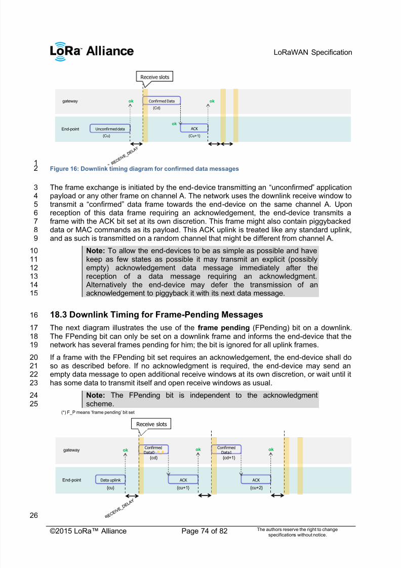
7/23/2019 LoRaWAN Specification 1R0
http://slidepdf.com/reader/full/lorawan-specification-1r0 74/82
LoRaWAN Specification
©2015 LoRa™ Alliance Page 74 of 82 The authors reserve the right to changespecifications without notice.
1Figure 16: Downlink timing diagram for confirmed data messages2
The frame exchange is initiated by the end-device transmitting an ―unconfirmed‖ application3
payload or any other frame on channel A. The network uses the downlink receive window to4 transmit a ―confirmed‖ data frame towards the end-device on the same channel A. Upon5reception of this data frame requiring an acknowledgement, the end-device transmits a6frame with the ACK bit set at its own discretion. This frame might also contain piggybacked7data or MAC commands as its payload. This ACK uplink is treated like any standard uplink,8and as such is transmitted on a random channel that might be different from channel A.9
Note: To allow the end-devices to be as simple as possible and have10keep as few states as possible it may transmit an explicit (possibly11empty) acknowledgement data message immediately after the12reception of a data message requiring an acknowledgment.13 Alternatively the end-device may defer the transmission of an14acknowledgement to piggyback it with its next data message.15
18.3 Downlink Timing for Frame-Pending Messages16
The next diagram illustrates the use of the frame pending (FPending) bit on a downlink.17The FPending bit can only be set on a downlink frame and informs the end-device that the18network has several frames pending for him; the bit is ignored for all uplink frames.19
If a frame with the FPending bit set requires an acknowledgement, the end-device shall do20so as described before. If no acknowledgment is required, the end-device may send an21empty data message to open additional receive windows at its own discretion, or wait until it22has some data to transmit itself and open receive windows as usual.23
Note: The FPending bit is independent to the acknowledgment24 scheme.25
26
gateway
End-point Unconfirmed data
{Cu}
Confirmed Data
{Cd}
ok ok
Receive slots
ok
ACK
{Cu+1}
gateway
End-point Data uplink
{cu}
ConfirmedData0+F_P
{cd}
ACK
{cu+1}
ConfirmedData1
{cd+1}
ACK
{cu+2}
ok ok ok
(*) F_P means ‗frame pending‘ bit set
Receive slots

7/23/2019 LoRaWAN Specification 1R0
http://slidepdf.com/reader/full/lorawan-specification-1r0 75/82
LoRaWAN Specification
©2015 LoRa™ Alliance Page 75 of 82 The authors reserve the right to changespecifications without notice.
Figure 17: Downlink timing diagram for frame-pending messages, example 11
In this example the network has two confirmed data frames to transmit to the end-device.2
The frame exchange is initiated by the end-device via a normal ―unconfirmed‖ uplink3message on channel A. The network uses the first receive window to transmit the Data0 with4the bit FPending set as a confirmed data message. The device acknowledges the reception5of the frame by transmitting back an empty frame with the ACK bit set on a new channel B.6RECEIVE_DELAY1 seconds later, the network transmits the second frame Data1 on7channel B, again using a confirmed data message but with the FPending bit cleared. The8end-device acknowledges on channel C.9
10Figure 18: Downlink timing diagram for frame-pending messages, example 211
In this example, the downlink frames are ―unconfirmed‖ frames, the end-device does not12need to send back and acknowledge. Receiving the Data0 unconfirmed frame with the13FPending bit set the end-device sends an empty data frame. This first uplink is not received14by the network. If no downlink is received during the two receive windows, the network has15to wait for the next spontaneous uplink of the end-device to retry the transfer. The end-16
device can speed up the procedure by sending a new empty data frame.17
Note: An acknowledgement is never sent twice.18
The FPending bit, the ACK bit, and payload data can all be present in the same downlink.19For example, the following frame exchange is perfectly valid.20
21
22Figure 19: Downlink timing diagram for frame-pending messages, example 323
The end-device sends a ―confirmed data‖ uplink. The network can answer with a confirmed24downlink containing Data + ACK + ―Frame pending‖ then the exchange continues as25previously described.26
gateway
End-point Data uplink
{cu}
Data0+F_P
{cd}
void
{cu+1}
ok
void
{cu+3}
okok
Data1+F_P
{cd}
void
{cu+2}
gateway
End-pointConfirmedData uplink
{cu}
ConfirmedData0+F_P+ACK
{cd}
ACK
{cu+1}
ConfirmedData1+F_P
{cd+1}
ACK
{cu+3}
ok
void
{cu+2}
Receiving a frame without the ACK bit set , serverretransmits Data1
okok ConfirmedData1+F_P
{cd+1}
(diag 2)

7/23/2019 LoRaWAN Specification 1R0
http://slidepdf.com/reader/full/lorawan-specification-1r0 76/82
LoRaWAN Specification
©2015 LoRa™ Alliance Page 76 of 82 The authors reserve the right to changespecifications without notice.
18.4 Data-Rate Adaptation during Message Retransmissions1
When an end-device attempts the transmission of a ―confirmed‘ frame toward the network it2
expects to receive an acknowledgement in one of the subsequent reception slot. In the3absence of the acknowledgement it will try to re-transmit the same data again. This re-4transmission happens on a new frequency channel, but can also happen at a different data5rate (preferable lower) than the previous one. It is strongly recommended to adopt the6following re-transmission strategy.7
The first transmission of the ―confirmed‖ frame happens with a data rate DR.89
Transmission nb Data Rate
1 (first) DR
2 DR
3 max(DR-1,0)
4 max(DR-1,0)5 max(DR-2,0)
6 max(DR-2,0)
7 max(DR-3,0)
8 max(DR-3,0)
The Data Rate max(a,b) stands for maximum of a and b values.10
If after a recommended 8 transmissions, the frame has not been acknowledged the MAC11layer should return an error code to the application layer.12
Note: For each re-transmission, the frequency channel is selected13randomly as for normal transmissions.14
Any further transmission uses the last data rate used.15
For example if an end-device sends a ―confirmed‖ frame first using DR5 and has to16retransmit 3 times (twice at DR5 then twice at DR4), the next frame transmitted will use DR417
Other example, if an end-device sends a ―confirmed‖ frame first using DR5 and does not18receive an acknowledge after 8 transmissions (2 at DR5, 2 at DR4, … , 2 at DR2), and the19application of this end-device re-initiates a ―confirmed‖ transmission a little later, the first two20transmission will be tentatively at DR2, then switch to DR1, then to DR0.21

7/23/2019 LoRaWAN Specification 1R0
http://slidepdf.com/reader/full/lorawan-specification-1r0 77/82
LoRaWAN Specification
©2015 LoRa™ Alliance Page 77 of 82 The authors reserve the right to changespecifications without notice.
19 Recommendation on contract to be provided to the network1
server by the end-device provider at the time of provisioning2
Configuration data related to the end-device and its characteristics must be known by the3network server at the time of provisioning. –This provisioned data is called the ―contract‖.4This contract cannot be provided by the end-device and must be supplied by the end-device5provider using another channel (out-of-band communication).6
This end-device contract is stored in the network server. It can be used by the application7server and the network controller to adapt the algorithms.8
This data will include:9
End-device specific radio parameters (device frequency range, device maximal10output power, device communication settings - RECEIVE_DELAY1,11RECEIVE_DELAY2)12
Application type (Alarm, Metering, Asset Tracking, Supervision, Network Control)13

7/23/2019 LoRaWAN Specification 1R0
http://slidepdf.com/reader/full/lorawan-specification-1r0 78/82
LoRaWAN Specification
©2015 LoRa™ Alliance Page 78 of 82 The authors reserve the right to changespecifications without notice.
20 Recommendation on finding the locally used channels1
End-devices that can be activated in territories that are using different frequencies for2LoRaWAN will have to identify what frequencies are supported for join message at their3current location before they send any message. The following methods are proposed:4
A GPS enabled end-device can use its GPS location to identify which frequency5band to use.6
End-device can search for a beacon and use its frequency to identify its region7
End-device can search for a beacon and if this one is sending the antenna GPS8coordinate, it can use this to identify its region9
End-device can search for a beacon and if this one is sending a list of join10frequencies, it can use this to send its join message11
7/23/2019 LoRaWAN Specification 1R0
http://slidepdf.com/reader/full/lorawan-specification-1r0 79/82
LoRaWAN Specification
©2015 LoRa™ Alliance Page 79 of 82 The authors reserve the right to changespecifications without notice.
21 Revisions1
21.1 Revision 1.02
Draft version of LoRaWAN3
4

7/23/2019 LoRaWAN Specification 1R0
http://slidepdf.com/reader/full/lorawan-specification-1r0 80/82
LoRaWAN Specification
©2015 LoRa™ Alliance Page 80 of 82 The authors reserve the right to changespecifications without notice.
22 Glossary1
2
ADR Adaptive Data Rate3 AES Advanced Encryption Standard4 AFA Adaptive Frequency Agility5 AR Acknowledgement Request6CBC Cipher Block Chaining7CMAC Cipher-based Message Authentication Code8CR Coding Rate9CRC Cyclic Redundancy Check10DR Data Rate11ECB Electronic Code Book12ETSI European Telecommunications Standards Institute13EIRP Equivalent Isotropically Radiated Power14FSK Frequency Shift Keying modulation technique15
GPRS General Packet Radio Service16HAL Hardware Abstraction Layer17IP Internet Protocol18LBT Listen Before Talk19LoRa™ Long Range modulation technique20LoRaWAN™ Long Range Network protocol21MAC Medium Access Control22MIC Message Integrity Code23RF Radio Frequency24RFU Reserved for Future Usage25Rx Receiver26RSSI Received Signal Strength Indicator27SF Spreading Factor28
SNR Signal Noise Ratio29SPI Serial Peripheral Interface30SSL Secure Socket Layer31Tx Transmitter32USB Universal Serial Bus33
34

7/23/2019 LoRaWAN Specification 1R0
http://slidepdf.com/reader/full/lorawan-specification-1r0 81/82
LoRaWAN Specification
©2015 LoRa™ Alliance Page 81 of 82 The authors reserve the right to changespecifications without notice.
23 Bibliography1
23.1 References2
[IEEE802154]: IEEE Standard for Local and Metropolitan Area Networks—Part 15.4: Low-3Rate Wireless Personal Area Networks (LR-WPANs), IEEE Std 802.15.4TM-2011 (Revision4of IEEE Std 802.15.4-2006), September 2011.5
[RFC4493]: The AES-CMAC Algorithm, June 2006.6

7/23/2019 LoRaWAN Specification 1R0
http://slidepdf.com/reader/full/lorawan-specification-1r0 82/82
LoRaWAN Specification
24 NOTICE OF USE AND DISCLOSURE1
Copyright © LoRa Alliance, Inc. (2015). All Rights Reserved.2
The information within this document is the property of the LoRa Alliance (―The Alliance‖) and its use and3disclosure are subject to LoRa Alliance Corporate Bylaws, Intellectual Property Rights (IPR) Policy and4Membership Agreements.5
Elements of LoRa Alliance specifications may be subject to third party intellectual property rights, including6without limitation, patent, copyright or trademark rights (such a third party may or may not be a member of LoRa7 Alliance). The Alliance is not responsible and shall not be held responsible in any manner for identifying or failing8to identify any or all such third party intellectual property rights.9
This document and the information contained herein are provided on an ―AS IS‖ basis and THE ALLIANCE10DISCLAIMS ALL WARRANTIES EXPRESS OR IMPLIED, INCLUDING BUT NOT LIMITED TO (A) ANY11WARRANTY THAT THE USE OF THE INFORMATION HEREIN WILL NOT INFRINGE ANY RIGHTS OF THIRD12PARTIES (INCLUDING WITHOUT LIMITATION ANY INTELLECTUAL PROPERTY RIGHTS INCLUDING13PATENT, COPYRIGHT OR TRADEMARK RIGHTS) OR (B) ANY IMPLIED WARRANTIES OF14
MERCHANTABILITY, FITNESS FOR A PARTICULAR PURPOSE, TITLE OR NONINFRINGEMENT.15IN NO EVENT WILL THE ALLIANCE BE LIABLE FOR ANY LOSS OF PROFITS, LOSS OF BUSINESS, LOSS16OF USE OF DATA, INTERRUPTION OFBUSINESS, OR FOR ANY OTHER DIRECT, INDIRECT, SPECIAL OR17EXEMPLARY, INCIDENTIAL, PUNITIVE OR CONSEQUENTIAL DAMAGES OF ANY KIND, IN CONTRACT OR18IN TORT, IN CONNECTION WITH THIS DOCUMENT OR THE INFORMATION CONTAINED HEREIN, EVEN IF19 ADVISED OF THE POSSIBILITY OF SUCH LOSS OR DAMAGE.20
The above notice and this paragraph must be included on all copies of this document that are made.21
LoRa Alliance, Inc.22
2400 Camino Ramon, Suite 37523
San Ramon, CA 9458324
Note: All Company, brand and product names may be trademarks that are the sole property of their respective25
owners.26