los alamos scientific laboratory of the … * & 3 (x2-74 report collection reproduction los...
TRANSCRIPT
LA-3546-MS
* & 3
(X2-74 REPORT COLLECTIONREPRODUCTION
LOS ALAMOS SCIENTIFIC LABORATORYof the
University of CaliforniaLOS ALAMOS ● NEW MEXICO
The Administration of Secondary Storage
in Nuclear Codes
UNITED STATESATOMIC ENERGY COMMISSIONCONTRACT W-7405-ENG. 36

,— LEGAL NOTICE—]This report was prepared as an account of Government sponsored work. Neither the UnitedStates, nor the Commission, nor any person acting on behalf of the Commission:
A. Makes any warranty or representation, expressed or implied, with respect to the accu-racy, completeness, or usefulness of the information contained in this report, or that the useof any information, apparatus, method, or process disclosed tn this report may not infringeprivately owned rights; or
B. Assumes any liabilities with respect to the use of, or for damages resulting from theuse of any information, apparatus, method, or process dtsclosed in ibis report.
As used in the above, “person acttng on behalf of the Commission” includes any em-ployee or contractor of the Commission, or employee of such contractor, to the extent thatsuch employee or contractor of the Commission, or employee of such contractor prepares,disseminates, or provides access to, any information pursuant to MS employment or contractwith the Commission, or his employment wtth such contractor.
All LA... MS reports are informal documents, usuaUy prepared fora specialpurpose and primarily prepared for use withinthe Labo-
ratory ratherthan forgeneraldistribution.Ttis report“ks not beenedited,reviewed, or verifiedfor accuracy. All L&. .w reportsexpress the views of the authors as of the time they were writtenand do not necessarilyreflectthe opinionsof the Los Alamos Scien-tificLaboratory or the finalopinionof the authors on the subject.
Printed in USA. Price $3.000 Available from the Clearinghouse forFederalScientificand TechnicalInformation,NationalBureau ofStandards,United L%XLteS Department of Commerce, Springfield, Virginia
1.
P

a
%“
LA-3546-MS IUC-32, MATHEMATICSAND COMPUTERS
TID-4500
LOS ALAMOS SCIENTIFIC LABORATORYof the
University of CaliforniaLOS ALAMOS ● NEW MEXICO
Report written: June 14, 1966
Report distributed:August 17, 1966
The Administration of Secondary Storage
in Nuclear Codes
by
William J. Worlton
1

ABSTRACT
The class of problems to which a particular computer can be
applied is closely limited by the specifications of the computer’s
storage hierarchy and the organization of the data flow. The storage
requirements of nuclear codes frequently exceed the capacity of the
main storage, and it is then crucial to be able to
levels of storage without large discontinuities in
transmission rate. The most exacting requirements
address ftn%her
access time and
occur when very
~ttle computing occurs between accesses to secondary storage. Recent
developments in computer storage technology and design offer systems
which do not have large discontinuities in the storage hierarchy. These
developments include Extended Core Storage (ECS), parallel disks and
drums, wide tapes, and magnetic strip transports. Extended core
storage is particularly important because it can be used to interface
the main storage with vem~ little gap in access time and transmission
rate. In spite of these developments, the flow of information must
still be programmed from one level to another because the addressing
techniqye is different for each level of the hierarchy. This burden
can be mediated for the user by the use of a “single-level” storage
system, a concept pioneered in the Atlas computer. The storage
3

requirements of two- and three-dimensional nuclear calculations will
continue to exceed the available systems, and the careful administration
of the storage system will be necessary to avoid severe limitations in
the development of these programs.

1. THE IMPORTANCE OF SECONDARY STORAGE
The selection of the storage system for a computer is a crucial
part of matching performance to requirements in computing systems. It
is a common error to focus attention only on the central memory, rather
than to place this memory in its context of actual usage with other
forms of storage. The flow of information throughout the system nmst
be analysed in order to achieve a correct balance between problem
requirements and storage capability. For example, the discontinuity
between the speed of main memory and the
imposed such a severe limiting factor on
main storage that this actually caused a
ment beyond which users seldom ventured.
speed of the tapes on the 704
problems which exceeded the
threshold in problem develop-
Oddly enough, the relative
nature of this gap has remained, even though both main memory and
secondary storage speeds have been improved. The 7030 main memory can
be read in 1.2 ~sec, but access to the disk is 4 to ~ orders of magnitude
more expensive in time; drums could provide a somewhat better interface
with this memory, but even here the discontinuitywould be 3 to h orders
of magnitude.
An ideal storage system for a computer would have a single
addressing method, a uniform access time, a cycle time commensurate
5

with the cycle time of
sufficient to hold all
is possible to build a
the Central Processing Unit (CPU), a capacity
information required, and a reasonable cost. It
storage system with all of these characteristics
except the last: a billion-bit main memory could be fabricated, but it
1would cost on the order of @ per bit. Since it is thus an economic
impossibility to satisfy large storage requirements by extending min
memory, a hierarchy of storage devices of larger capacity but lower
capability and cost must be resorted to, and this raises a number of
2problems. First, problem preparation is more complex because of the
need to address several types of storage and to move data to the
fastest member of the hierarchy. Second, there is a greater likelihood
of error in the calculation because secondary storage devices are less
reliable than main memory. Third,
because of the slower access times
storage. These problems imply the
selection of e~ipment
if artificial barriers
problem development.
the calculation time is increased$
and transmission rates of secondary
need for great care in both the
and the administration of available storage space
are not to be erected for both running time and
The importance of secondary
evidently continue to increase for
access to secondary storage: this
storage has been increasing, and will
some time. Consider the frequenc~ of
is proportional to the speed of the
ccmputer, inversely proportional to the main memory capacity, and
proportional to the volume of information regpired. All other things
being equal, when computers differ only in speed, such as the 7094 and
●
1
6

I
the 7094-11, the faster one will have a
Similarly, the smaller the main memory,
higher access fkequency.
the more fre~ent must he the
use of secondary storage. If 100,000 words must be processed in blocks
of 1,000 words due to limitations in buffer size, then 100 accesses are
necess=y; if the buffer size could be increased to 10,000 words, only
10 accesses wouldbe necessary. Ftilly, if computer speed and memory
size wem held constant and the volume of information handled by a
program were increased, the frequency of access to secondary storage
would increase. This has in fact been happening due to the application
of computers to a broader class of problems. These three parameters do
not vary at the same rate, however. Computer speed has been increasing
faster than main memory capacity, as can be seen in Figure L If
speed and memory size had increased at the same rate, the points of this
figure would all fall on the “line of equal development”; in fact, they
fall considerably above this line. The balance between speed and
memory capacity can
memory capacity (in
the same horizontal
be compared easier if the speed is dividedby the
704 units) as in Figure 2. Computers falling on
line have the same balance between speed and memory
capacity; on a vertical line, the speed is out of balance to the capacity
in the higher points. Note that the highest speed computers are tending
to greater imbalance, emphasizing the importance of secondary storage.
7

I000 !-
1 I I I IHII I I I I 111~
~360/916800
loo& 06600 741- /1
1= — —-.-4-- /
1azlz 01108 036W R)
070307094 II
.
1=Io 709401107
Y“+.G
, #
r *Y’I I I I I 1111 I I I I 1111
I 0010
relative memory
l?5gureL Relative CHkS??eed VE
8
capacity
?4em0rYCapacity

11111111111I
I—
I
———
o0(9coo
●
mloz“
100030F0
●
—
T
1111111I
c111111
II
Ir
o00
000—o0o
a)vii

2. REVIEW OF MAIN MEMORY DEVELOPMENTS
Because main memory is so hrportant in judging secondary storage
requirements, it may be well to review recent developments in main
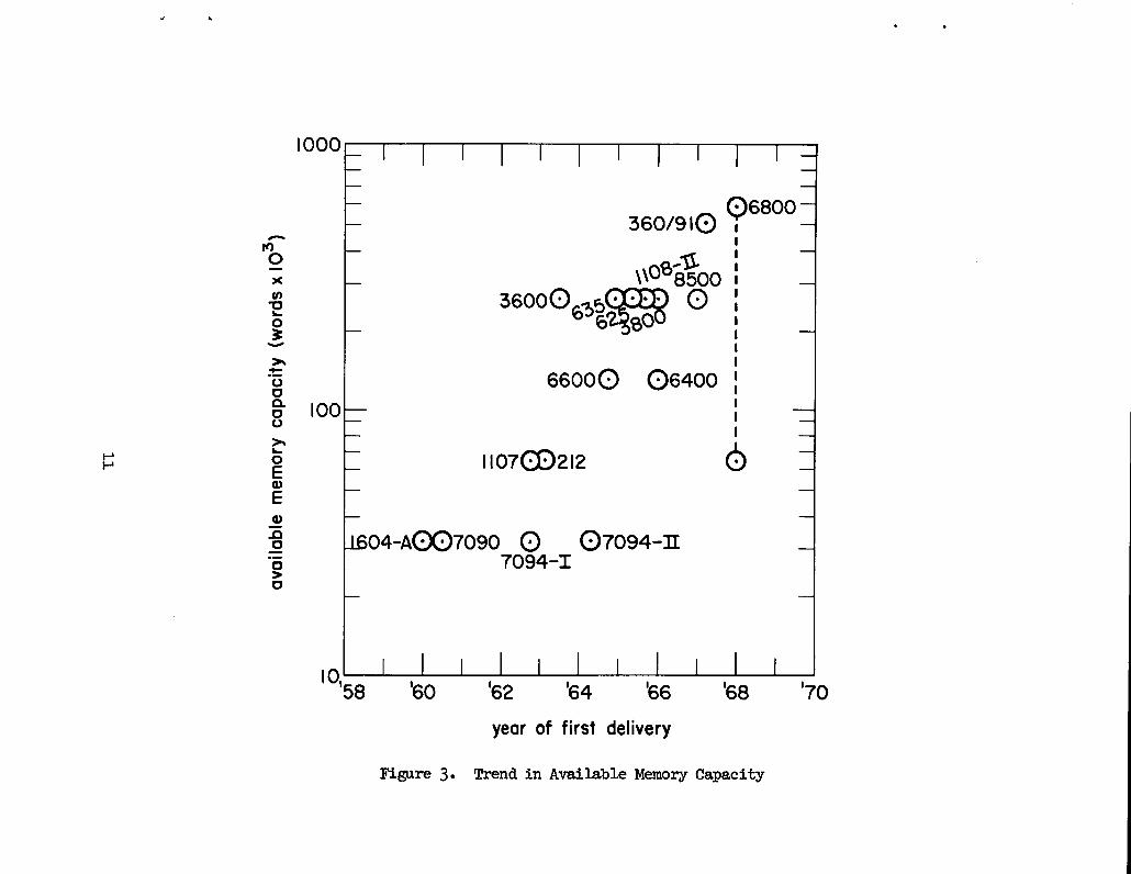
memory design. Figure 3 shows the trend in available memory capacity
relative to the year of first delivery of typical.scientific computers.
Computers with a 32K memory capacity dominated the field from the days
of the 704 to about 1962, but since then there has been a marked in-
crease in the main memory capacity offered with new designs. Currently
available computers offer capacities fhwm 32K to 512K, but actual
installations are more often in the 32K to 128K range due to the rela-
tively high cost of main memory. This diagrsm is somewhat deceptive in
that a trend line would seem to extrapolate to higher and higher capaci-
ties in main menmries, but in practice there is some hesitation in
making this prediction.
time,
times
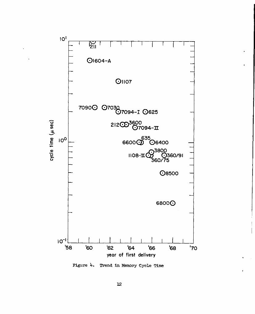
These same computers show a trend toward lower main memmy cycle
as illustrated in l!lgurek. In less than a decade, memory cycle
have decreased about an order of magnitude,,and this trend is
expected to continue; we should see 50 to 75 nsec memories offered with
computers in the next decade.3 The actual cycle times shown in the
figure have been effectively decreased even flmther by interleaving
several independent boxes of memory, which in the most fkworable case
(no access conflicts) provides access tomemo~ in the read time, which
is usually less than half of the fill cycle time. Rrthermore, when
,
,.
1111I
II
111111I
—————————
o0&------ ------
---a
o .00u)
Q
+-0
1111I
111111I
I00
(EO
Ix
SP
JOM
)@
mdm
~lqOl!OAD
11
10’I
1211u I I I I I I I
0t604-A
01107
870900 0703
● 7094-10625
212cD3&094 =
6600@635@6400
llo8-@388360/91360/75
F 08500
6800~
, ()-l I I I I I I’58 ’60 ’62 ’64 ’66 ’68 ’70
year of first delivery
Ngure 4. Trend in Memory Cycle Time
.
,
12
.
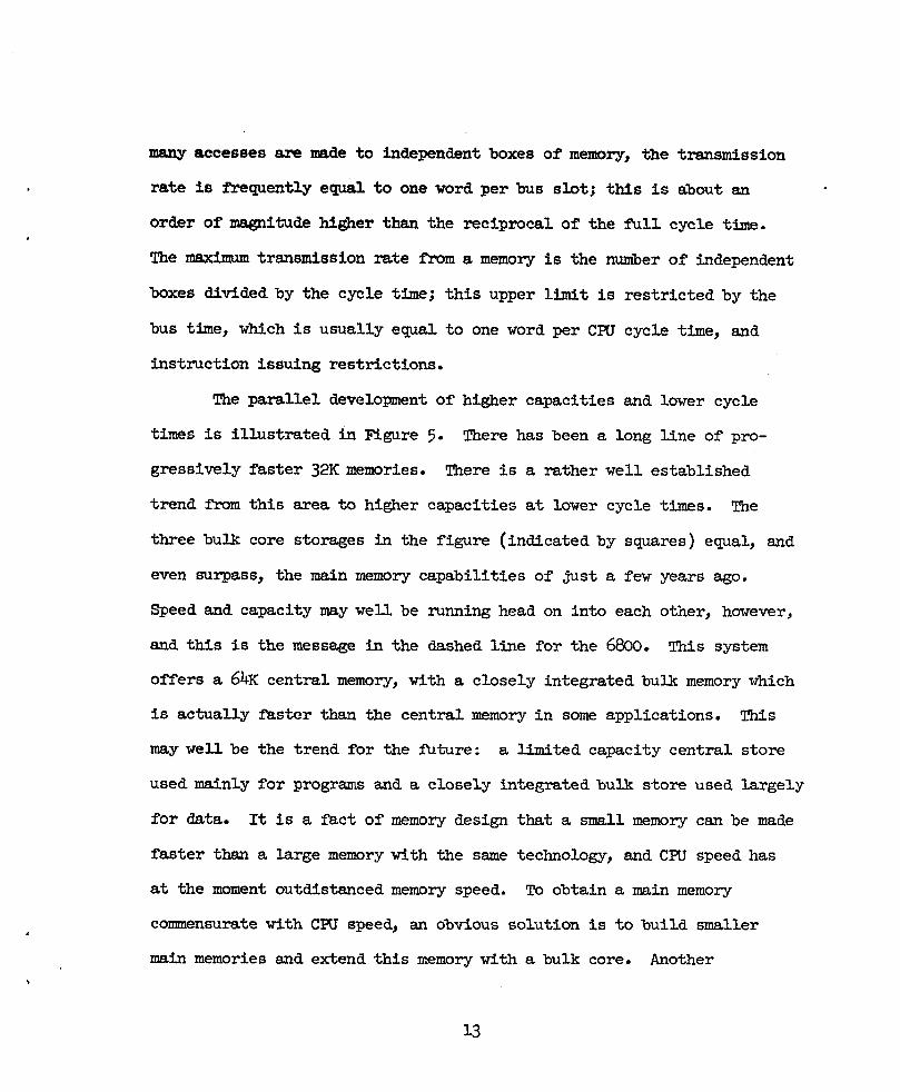
_ acce=Jes ~ -de to ~d.e~ndent boxes of memory, the transmission
rate is fYeqpently equal to one word per bus slot; this is about an
order of magnitude hi~er than the reciprocal of the full cycle time.
The maximum transmission rate from a memory is the number of independent
boxes divided by the cycle time; this upper limit is restricted by the
bus time, which is usually equal to one word per CPU cycle time, and
instruction issuing restrictions.
The parallel development of higher capacities and lower cycle
times is illustrated in Figure 5. There has been a long line of pro-
gressively faster 32K memories. There is a rather well established
trend from this area to higher capacities at lower cycle times. The
three bulk core storages in the figure (indicated by squares) equal, and
even surpass, the main memory capabilities of just a few years ago.
Speed and capacity may well be running head on into each otiner,however,
and this is the message h the dashed line for the 68oo. This system
offers a 6bK central memory, with a closely integrated bulk memory which
is actually faster than the central memory in some applications. This
may well be the trend for the future: a Mmited capacity central store
used mainly for programs and a closely integrated bulk store used largely
fOr data. It is a fact of memory design that a small memory can be made
faster than a large memory with the same technology, and CRJ speed has
at the moment outdistanced memory speed. To obtain a main memory
commensurate with CPU speed, an obvious solution is to build smaller
main memories and extend this memory with a bulk core. Another
\
13

.b
o.
~“’’’’’x’”’1
1I
rr
I,
x,,
,m-
--lx
4(9mml
10.—
:00 .0 “Sm0 .ml
Fld—
—w
-
bcn
+%
n\-n
1 ~~~os-/!-/!’U
)ulm
m0/$3
0 .-0
----------
---00a)
~1’’””
Qo
II
II
1I
II
I1
1I
n“
o“
o—
—
‘1f,
14

I
r
.
indication of this incompatibility of speed and capacity is the fact
that the 360/91 is designed to be about as fast as the 68oo, but it
uses a memory several times slower. We may wellbe faced with a choice
between speed and capacity, snd this will probably lead to a finer
structure of main memory: a small, very *st local memory; a larger,
but slower, main memory;
implymn’e effort in the
attractive compared to a
and a very large bulk storage. ~S would
administration of main memory and is not very
large memory of uniform access.
A
memory.
the last
final trend to be aware of is the decreasing cost of main
Ngure 6 shows the decrease of main memory cost per bit over
six years. Present costs are clustered around 20~ per bit, or
about @2.50 for a 64-bit word. Even at these lowered costs, million-
word memories are out of the qyestion, and even 512K word memories are
Mfficult to dustify economically.
These three trends of larger memory capacities, faster memory
speeds, and lower memory costs would almost justify Leibnitzk belief
that this
blase and
facturers
and still
is the best of all possible worlds: It is easy to become
take these achievements for granted, but the computer manu-
have done a remarkable job of advancing the state of the art
retaining economy in their products.
3. STORAGE SYSI!EMORGANIZATION
3.1 Central Memory Organization. The conventional computer organization
uses the main memory for all transfers of information to or f!romeach
15

s
b●8
I
o.:
0.
09b010●
05●
03●
I .0I I I I I
12
o_●
o●
1’ I I’60
I‘6I
I’62
I’63
I’64 ’65 ’66 g7
013●
07●
2
I@4~ I
06●
f~rst delivery
Main Memory Costs
16
—
.
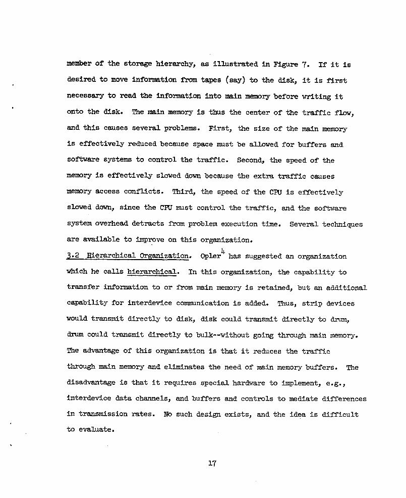
metier of the storage hierarchy, as illustrated in Ngure 7. If it iS
desired to move information from tapes (say) to the disk, it is first
necessary to read the information into main memory before writing it
onto the disk. The main memory is thus the center of the traffic flow,
and this causes several problems. First, the size of the main memory
is effectively reduced because space must be allowed for buffers and
software systems to control the traffic. Second, the speed of the
memory is effectively slowed down because the extra traffic causes
memory access conflicts. Third, the speed of the CPU is effectively
slowed duwn, since the CPU must control the traffic, and the software
system overhead detracts from problem execution time. Several techniques
are available to improve on this organization.
3.2 Hierarchical Organization. 0pler4 has suggested an organization
winch he calls hierarchical. In this organization, the capability to
transfer information to or from main memory is retained, but an additional
capability for interdevice communication is added. Thus, strip devices
would transmit directly to disk, disk could transmit directly to drum,
drum could transmit directly to bulk--without going through main memory.
The advantage of this organization is that it reduces the traffic
through main memory and eliminates the need of main memory buffers. The
disadvantage is that it requires special hardware to implement, e.g.,
interdevice data channels, and buffers and controls to mediate differences
in tr~stission rates. No such design exists, and the idea is difficult
to evaluate.
.
17

CPU
MAIN
MEMORY.
, BULK
t 4
DRUM
*
DISK.
STRIP
?
TAPE\
* ?UNIT
RECORD6
.
.
Figure 7. Central Memory Organization
.

.
.
. Bulk storage can be used to mediate
the flow of information throughout a system in a more efficient manner
than the central memory organization, as illustrated in Ngure 8. Here
information can flow directly to or fmm the bulk storage in addition
to main memory, and this eliminates much of the traflic from main
memory and moves the buffers out of the main into bulk storage. By
anticipating the flow of information within a calculation, it is some-
times possible to eliminate the delays inherent in the slower devices
by moving the information to bulk ahead of time. This gives the effect
of bulk speeds for all secondary storage requirements but takes con-
siderable effort in optimum programming by the user of a very efficient
software system. The IBM360/91 has
organization.
3.4 Coupled-Computer Organization.
essentially this
Coupled-computer
type of
organizations are
not new, but their hportance may well be increasing in the design of
ultra-high-speed computers, for the simple reason that it takes a
separate computer to handle 1/0 for a fast scientific computer. A
representative design is illustrated in ltigure9. The interface between
the computers maybe as simple as a transmission line, as in the 7094/
7044 system; it maybe a disk, as in the 7090/1410 system; it maybe
bulk storage, as in a 6600/6411 system; or, it may be a combination of
these. The basic advantage here is that the control of information
flow is handledby a separate computer, thus eMminating the overhead.
time for the large scientific processor. The power of a large-scale
,
lg

CPU 1 4& \
f
MAIN — BULKMEMORY
--r=l
--P-l
--tQzl~ TAPES I
---1 UNIT
RECORD
Ngure 8. Central/ECS Organization
.
I.
.
20

I* f *MAIN ~ BULK
Ioc—MEMORY MEMORY9
●
4 A DISK● *
\ t
DRUM
f
STRIP# ●
a
TAPES 1 1
*
aUNIT 4
RECORD& ●
Figure 9. Coupled Computer System
21

processor is not needed to control secondary storage and 1/0 traffic,
and it can devote its power to high-speed calculation. Another
advantage is that it moves much of the software out of main memory. The
smaller computers range in size from just a message switching center up
to full-scale cmputers which can perfozm conversions and compilations.
● One-Level Storage Organizatione lCilburn5and his associates at the
University oflknchester designed a storage organization for the Atlas
which allows the user to address secondary storage as though it were all
part of main memory. Main memory is arranged in 32 blocks of 512 words,
called “pages,” and associated with each page is a Page Address Register
(PAR), which identifies the current contents of that page. The upper
portion of a memory address is compared with all 32 PAR’s; if a match
is found, access to that page is allowed. If no match is found, an
interrupt to a supervisor progrsm occurs, and the supervisor compares
the psge identificationwith the table of contents of a high-speed drum.
One page is always left empty in main memory; as soon as the drum page
with the correct identifier is available under the reading heads, this
page is read into memomJ. The PAR for this memory page is then updated,
an empty memory page created by writing out another page onto the drum,
and the table of contents of the drum updated. The selection of which
page to remove ilrommemory is very important for overall efficiency,
and this decision is =de on the basis of “use” digits associated with
each page which are used to determine which page is the least active.
22

Although the Atlas design uses this “paging” method for only the
main memory and the drum, the method can be extended to a fill hierarchy
of seconbry storage devices, allowing the user to address the full
capacity of all
There is
the access time
secondary storage as though it were part of main memory.
a potential penalty for this convenience however, since
must still be paid for the information. If the user
ignores the need to optimize
storage for random access as
this organization convenient
the use of main memory and uses secondary
though it were main memory, he will find
but inefficient. The algorithms for
determining which page to remove from memory can never replace the
user’s knowletie of which p-e is needed next, and this can lead to a
page being removed
instruction--which
Several methods to
concept are known:
for one access, and returned for the very next
effectively turns the computer into a drum computer.
improve the efficiency of the one-level storage
(1) to allow the user to dynamically specifY the
expected activity level for his assigned pages, (2) to use multi-
programming to cover the secondary storage access and transmission
times, and (3) to use content addressable PAR’s so that the comparison
of an address with memory contents is essentially instantaneous.
In summary, the one-level storage organization offers automatic
relocatability of storage and the convenience of addressing all storage
devices as though their contents were in main memory. Great care must
be tslcento avoid inefficiency, however.
23
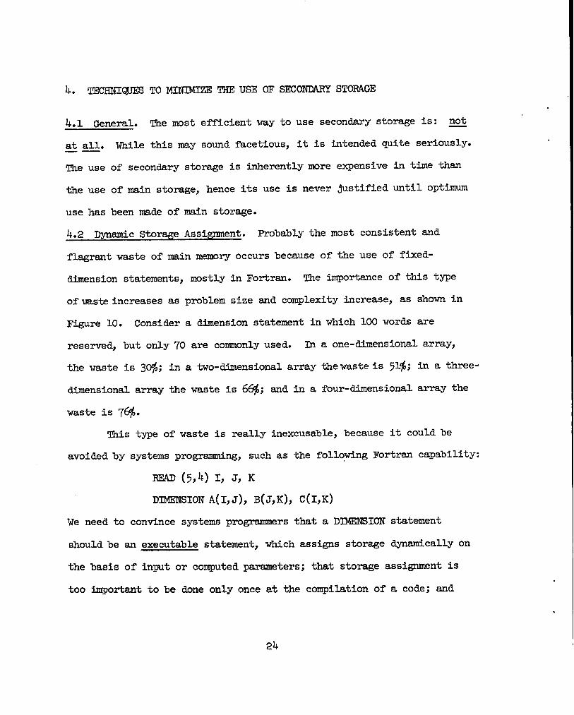
4. TEcmmmS
401 General.
at all. While.—
TO MINIMIZE THE USE OF SECONRARY STORAGE
The most efficient way to use secondary storage is: not
this may sound facetious, it is intended quite seriously.
The use of secondary storage is inherently more expensive in time than
the use of main storage, hence its use is never justified until optimum
use has been nde of main storage.
4.2 ~smic Storage Assignment. Probably the most
flagrant waste of main memory occurs because of the
consistent and
use of fixed-
dimension statements, mostly in Fortran. The importance of this type
of wasteincreases as problem size and complexity increase, as shown in
Figure 10. Consider a dimension statement in which 100 words are
reserved, but only 70 are commonly used. In
the waste is 3&P; in a two-dimensional array
dimensional array the waste is 66$; and in a
waste is 76$.
a one-dimensional array,
thewasteis 51%; in a three-
four-dimensional array the
~is type of waste is really inexcusable, because it couldbe
avoided by systems programming, such as the folloting Fortran capability:
READ (5,4) I, J, K
DIMENSION A(I,J), B(J,K), C(I,K)
We need to contince systems programmers that a DIMENSION statement
should be an executable statement, which assigns storage dynamically on
the basis of input or computed parameters; that storage assignment is
too important to be done only once at the compilation of a code; and
.
24

I,0
0.9
0.8
0,7
0.6
n_z\ 0.5&
0.4
0.3
0.2
0. I
II
II I
II
II I I I I
let N=no, of words assigned;.
m=no. of words used;D=array dimension.
.
.
.
.
.
.
0.003 04 05 06 07 08 09. . ● . . . . I.0
(m/N)
Figure 10. Waste of Storage with Fixed Dimensions
25

that storage assignment should be done for each problem run. The
variable dimensioning allowed in Fortran-IV is only half of the
solution, because the main program requires fixed
using this capability, however, it is possible to
around this inadequacy by assigning a single data
calculating how much of it is actually needed for
Mmensions. By
partially program
block for all data,
each array, and
packing all arrays together without waste. This method of using a
fixed dimension for total usage is superior to the method of using a
fixed dimension for each array, but it still leaves unused storage.
4.3 Multi-Function Usage. Although some storage requirements remain
constant throughout a code, others are often of a recurring nature,
occurring and disappearing. This latter situation allows the use of
EQUIVALENCE techniques, which are so commonly lmown that it is only
necessary to mention them.
4.4 Telescopic Methods. A less obvious technique, but one which is
equally valuable is the method of “telescoping” arrays. Any array which
can be calculated with a first-order recurrence relation can be tele-
scoped into a single memory cell. For example, assume that we wish toI
calculate R = E ai,‘here ai+l =f(ai); then it is unnecessary to
i=lallow more than a single cell for the a-array. The same method can be
applied to higher order recurrence relations by assigning only the num-
ber of cells which equals the order of the recurrence relation rather
than the length of the array.
.
.
26

The DDF tie-dimensional transport code uses this method; its
inner loop consists of four third-order recurrence relations. The
storage reqyired is telescoped from a single four-dimensional.array to
four three-dimensional arrays. Let the array dimensions be given by
I, J, G, andM. The origina3 requirement is I*J+KYM, and the telescoped
requirement is 2*I~W3 + 2*JWCG; this saves storage whenever
I*J/(I+J)>2, which is always true in a real problem environment.
The magnitude of the saving is very impressive: For I=J=30, G= 25,
and M=16, the telescoping technique would save 310,000 words of
storage.
4.5 Mapp”~ Ibnctions. An auxiliary tinction which defines the region
of applicability of another fhnction is called a mappinq function. Ii
numerical formulations these occur as recursive subscripts; e.g., in the
term
a“ ‘i, j’
the second subscript is defhed by a mapping finction,
functions are valuable in computer programming because
‘i, j “ Mapping
they can be used
to conserve storage. The amount of storage required for the above
fhnction is (M*N+I*J), where the capitalized index indicates its
maximum value. This function couldbe expressed without the use of
the
but
mapping function as
cm,i,j’
the storage required would then be three dimensional: M++I+$J. ~
27

this example, the mapping function would
(M*N+ I*J) < (M*I*J), that is, whenever
I-N-J
‘>-N”
conserve storage whenever
.
.
This ineq-mlity points out two things about
in programming: first, they should be used
the use of mapping fimctions
only when the numiberof
elements in the mapping function exceeds the maximm value of the
mapping function (i.e., where I*J>N); and second, they should be used
. only when the fhnction to be mapped is nmltidimensional (i.e., where
M>l).
4.6 Sparsely Populated Arrays. h array which has a large population
of zero elements can be more efficiently stored if only the nonzero
elements are retained, and a binary control vector is used to control
the use of the array. The control vector is a one-bit-per-element
array which corresponds to each element of the initial array; zero bits
correspond to zero words, and one bits correspond to nonzero words. If
the initial array has W total words in it, of which only N are nonzero,
and there are B bits per word, then storage can be saved whenever
N+;CW ,
or, put in terms of the usage density, N/W, whenever
N B-1V<—.B
For example, in a computer with 64 bits per word,
the control vector will save storage whenever the
than 0.984.
the nonzero army plus
usage density is less
28

h practice, the programmhg for these compacted arrays and
their associated control vectors is considerably more complex than
programming for the initial array, and it is only when the usage
the
density is very low that the extra effort is undertaken. This effort
could be reduced if there were bit-manipulation facilities in Fortran,
and these would be easier to implement if the hardware included bit-
manipulation facilities,
and an all-ones count.
me ~rts.nce Of
specifical& including
this method of storage
a left-zones count
conservation increases
as problem size increases: a usage density of 25% in a
offers a potential saving of less than 75 words, but in
word array the potential saving is almost 74,000 words,
the word length of the computer.
5. AREVIEW OF SECONIYLRYSTORA~ DEVICES
MO-word array
a 100,000-
depending on
~.1 Scope. The secondary storage devices considered here will be
limited to those which are used as extensions of main memory: bulk
core, drums, disks, and magnetic strip detices. Tapes are excluded
for two reasons: first, their use in nuclear codes has been covered
6in an excellent paper by Cadwell; and second, the serial nature of the
recording makes them inappropriate for random retrieval of information.
Photographic storage devices, or “write-once” stores, are not considered
because they are essentially limited to reading functions and cannot
extend the read/write capability of main memory.
29

5.2 Continuity in Secondary Storage. Given that it is necessary to
extend the storage capacity by using a hierarchy of storage devices
rather than a homogeneous storage system, this hierarchy should offer
extra capacity in uniform increments of access time. A storage system
in which there are large gaps between the access times of the devices
will impose an artificial barrier to progrsm development. The gap
between the access times of main memory and the fastest device in the
secondary storage hierarchy can quite accurately be called tineinterface
#a-Q. The performance characteristics of the device which interfaces
main memory are very important, because this device must buffer access
to other members of the hierarchy. If tineinterface gap is small,
then progrsm development beyond main memory capacity is orderly; if the
interface gap is large, then program development will be retarded. For
example, if the interface device is magnetic tape, the interface gap is
at least milliseconds and at most minutes; if the interface device is
_etic striPs~ the titerface gap is several hundred mil.liseconds;if
the interface detice is magnetic disk, the interface gap is tens to
hundreds of milliseconds; if the interface device is magnetic drum, the
interface gap is a few to tens of milliseconds; and if the interface
device is bulk storage, the interface gap is a few microseconds. It is
usefil to define the access ratio, i.e., the ratio of the access time of.— —
the secondary storage device to the access time of main memory. The
6access ratio for magnetic strip devices is on the order of 10 ; for
disks it is on the order of 105; for drums it is on the order of 104;
.
30

and for bulk it is on the order of 101.
fmm one computer to another, and are an
equipment selection.
These numbers vary, of course,
important consideration in
Notice that there are no storage detices which have an access
ratio of 102 or 103; that is, for a computer with a l-psec main memory,
there is no secondary storage device available which has an access
time of 100 ~sec to 1 msec. There is a performance area which would
have valuable applications if
between the cost of drums smd
word.
. Magnetic Strip Devices.
secondary storage devices is a
Although designs vary in their
me~um is a strip of polyester
it couldbe made available at a cost
the cost of hulk storage, say #0.50 per
The largest total capacity available in
category I have called magnetic strip.
method of implementation, the recording
with an iron oxide coating;7 l?igure11
shows the organization of the IEM-2321. These strips are 2-1/hby 13
by 0.005 in.; there are ten strips to a subcell, 20 subcells to a data
cell, and 10 data cells to a data cell.array. The total capacity is
hOO million 8-bit bytes, or 3.2 billion bits. The strip transport
mechanism is shown in ltlgure12. The access times are comparatively long,
several hundred milliseconds, and the transmission rates are relatively
low. The main adwntages of these devices are the large total capacity
and the low cost per word of storage.
5.4 _etic Disks and Drums. The first disk unit was made by the
Bureau of Standards in 1952;8it consisted of a stack of donut-shaped
31

DATACEUARRAY=400MILLION BYTES
(10 CEIJS)
DATACELL=40MILLION(w SU6CEUS)
%CEu sz/kLION
(lo STRIPS]
STRIP = wo,ooo BYTESA~5 CY~INDER)
CYUNDER = 409(200
TkAkx& +!,000
.
*
Figure 11. Organization of the IEM-2321
32

STRIP PICKUPCYCLE
.
urn
MagneticHead
-ZJi!iEse’arati”nfin’e”
1.Separation
-3E
Strip PickupHead
2. Strip Pickup
4. Pickup Head Latched3. Strip
To DrumFigure 32. Access Mechanism of the IEM-2321
33

plates with an access mechanism in the center that moved axially to
the correct Msls, which was then accelerated and read. The first
commercial disk was the RAMAC, introducedby IBM in 1956. It consisted
of a stack of 50 plates accessed by a single access am with two read-
write heads, one for the upper and one for the lower surface. The
access arm was positioned vertically to the correct plate, moved
horizontally to the correct track, and the
when the rotation of the plate brought the
head as sho%m in Figure 13. Although this
information read (written)
correct position under the
can be classified as a
“three-motion” device, four motions were often necessary, since
repositioning of the access arm regyired a horizontal withdrawal of
the arm before the other motions could take place. ?!hisdesign was
i.mprovedupon with the design of access mechanisms with an access arm
per plate, which eliminated the withdrawal and the vertical motion.
By placing more than one read-write head per arm, the amount of
horizontal positioning mtion can be reduced. The logical extension
of this design is the “head-per-track” disk offered by Burroughs, in
which there is no horizontal motion necessary. CDC has recently
announced an “opposing-access” disk, Which is mchmore stable than
single access devices. Two stacks of plates are used rather than
~st one, anda central access arm positioner moves the opposing
access arms at the same time.
Access techniques for drums have developed from the single read-
write head which moved along the surface of the &mm, to the multiple
34

..
mn
1-0zhz0
0 mIdar*
-
n
C9
zu)0a-
cl0
0 d-
1-0zI~t-
0N
35
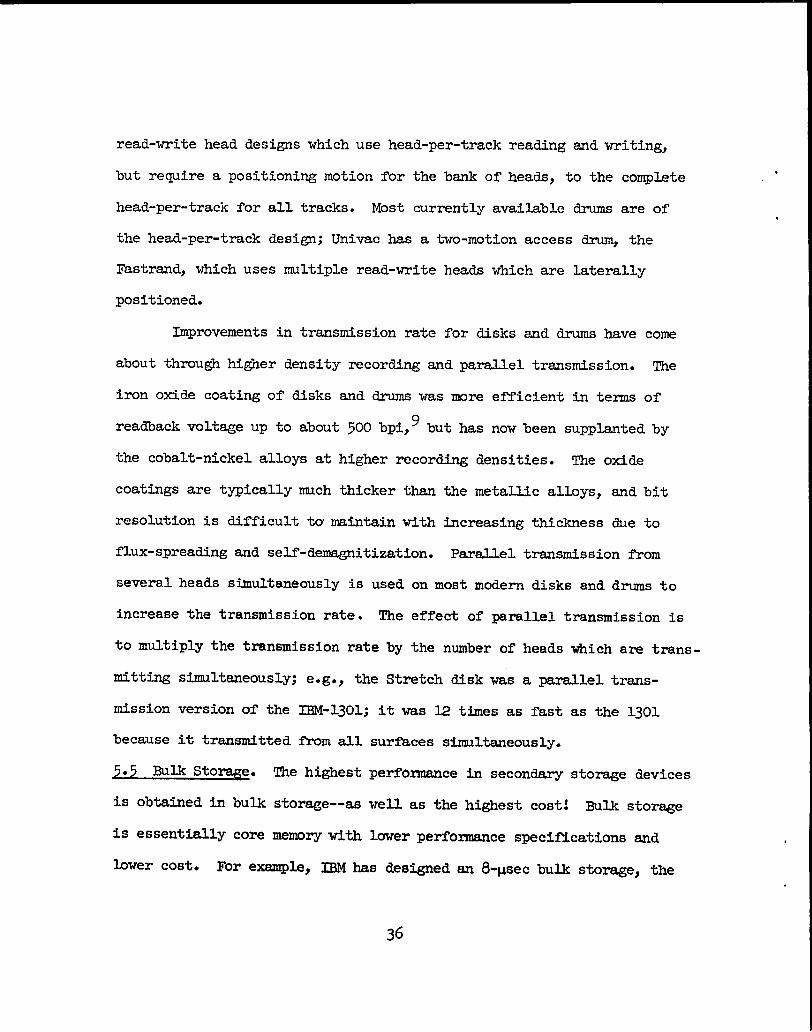
read-write head designs which use head-per-track reading and writing,
but reqyire a positioning motion for the bank of heads, to the complete
head-per-track for all tracks. Most currently available drums are of
the head-per-track design; Univac has a two-motion access drum, the
Fastrand, which uses multiple read-write heads which are laterally
positioned.
Mprovements in transmission rate for disks and drums have come
about through higher density recording and parallel transmission. The
iron oxide coating of disks and drums was more efficient in terms of
readback voltage up to about 500 bpi,9 but has now been supplantedby
the cobalt-nickel alloys at higher recording densities. The oxide
coatings are typically rmch thicker than the metallic alloys, and bit
resolution is tifficult ta maintain with increasing thickness due to
flux-spreading and self-demagnetization. Parallel transmission from
several heads simultaneously is used on most modern disks and drums to
increase the transmission rate. The effect of parallel transmission is
to multiply the tnnsmission rate by the number of heads which are trans-
mitting simultaneously; e.g., the Stretch disk was a parallel trans-
mission version of the IEM-1301; it was 12 times as fast as the 1301
because it transmitted from all surfaces simultaneously.
● Bulk Storage. The highest performance in secondsry storage devices
is obtained in bulk storage--as well as the highest cost! Bulk storage
is essentially core memory with lower performance specifications and
lower cost. For example, IBMhas designed an 8-~sec bulk storage, the
.
36

.
.
2361, which sells for less than $2 per word, as cmpared to about
#12.50 perword fortheir 0.75-~sec mainxnemory. CIXhas designeda
3.2-~sec bulk store for their 6@0 and a 1.6-~sec bulk store for their
6&)o. These CIX!designs have a very high transmission rate due to the
fact that they fetch 8 and 16 words, respectively, in the memory cycle
time. Because bulk storage
secondary storage device to
tiding a buffer between the
secondary storage devices.
is the closest in performance of any
main memory, it is very valuable in pro-
min memory and the slower, larger capacity}
3.6 ~luation of Secondary Storage Devices. Figure 14 is a state-of-
the-art diagram for disks, drums, and strip devices; it plots the
transmission rate and the capacity of moving media storage devices
attached to current computers. The symbols ctLfferentiatebetween the
types of devices; the numbers are an identification key, the first digit
identifying the manufacturer and the second the device in his line. ~
this diagram it is an advantage to ac’hievethe upper-right-hand corner,
indicating larger capacity and hi~ transmission rate. If the highest
points in the diagram were connected,
of transmission rate for moving-media
7mound 1 to 2 x 10 bits per second.
choose between disks and drums as far
they vould indicate the frontier
storage devices; they cluster
Note that there is little to
as transmission rate is concerned.
On the far right of the diagram is the frontier of storage capacity, and
the devices which are farthest to the right are the magnetic strip
devices. Note, however, that higher capacities than about 109 bits CS21
37

.
108
r
11111
8 ‘&”72 74
105 L-
107
—--
~ disk~ drum
m strip
61q+l
4°731
I 111111 111111I 111111I08 I 09 I 0’0
capacity (bits)
Figure 14. State-of-the-Art for Transmission Rate and Capacity
.
38

.
.
be achieved only by accepting lower transmission rates. Two of these
@nts seem to be out of place: the disk marked “U-” and the drum
marked “73”. What is common to the upper-left cluster is that they
are all head-per-track devices, including the disk; the upper-right
cluster is characterized by two-motion access, including the drum.
The drums in the lower left are low-cost, low-performance devices.
For blocks of less than about 103 to 104 words, transmission
rate is less important than access time, and Figure 15 is a state-of-the-
art diagram for access time and capacity. Here the most advanced
devices are in the lower-right-hand corner, indicating large capacity
and luw access time. This diagram separates the types of devices
rather distinctly by their access motion, with the strip devices
showing up with highest capacity, but longest access the, two-motion
access disks and drums in an intermediate position, and one-motion
access drums and one disk having lowest access and capacity. While
advances in the state-of-the-artwill move points in this diagram
lower and to the right, the relationship between the classes will
continue. Note also that it is difficult to say that any one of these
classes is the “best” in any absolute sense, since they each have their
advantages. The position of the two-motion detices can be lowered in
the diagramby pre-positioning, and they
with one-motion devices.
While the total capacity has its
then compete quite effectively
place in storage,system desQn,
another parameter which is often overlooked is equally important: the
39

o
‘o
—I
———————
O .mf-
_‘o
I11111
111111I
—m0
a0—
ml
m0.
—
0 .u)
0 .0*F0AN
111111I
1111
’20
-L-
1J
111111I
I~
‘o‘o
g—
.
4’0

.
.
addressable capacity without repositioning. Figure 16 shows this
parameter plotted against access time, and here it is an advantage to
achieve the lower-right part of the diagram. The identification key
here is different than the previous diagrams. Again there are three
clusters of points, and for this parameter there is a clear admantage
to be seen: the head-per-track devices have a significant advantage
over the two- and three-motion devices. Item “7” is the Burroughs
head-per-track disk. The two disks which are clustered with the strip
devices are removable-pack disks, and this cluster has a common feature,
i.e., it is possible to physically rennve the recording medium from the
transport. This is a valuable feature, but it is paid for by a low
capacity without repositioning. As a rule of thunib,there is approxi-
mately an order of magnitude between the removable-media devices, the
two-motion disks and drums, the head-per-track drums, and the head-per-
track disk. It muld appear that the largest capacity without reposi-
tioning is achievable in a head-per-track disk.
Figure 17 shows the cost per bit of storage plotted versus the
storage capacity, and here bulk storage is included. In this dlagrsm,
it is an advantage to achieve the upper-left corner, and this position
is held by the magnetic strip devices.
equal in cost to the two-motion access
because they are low capacity devices.
storage costs could be drawn from this
Two other strip detices are
disks and drum; this is probably
A rule of thumb for secondary
diagram: there is about an
order of magnitude in cost between bulk, head-per-track
41
drums, disks

~‘O
II111111I
111111 I
—
L
.
w
xtn.-U
•1tn—
.—
f=—
HH
HI
IH
‘o*o
‘o
?!0
‘o
o—
——
——
(SUJ)
auu
~ssamo
a6DJi3AD
a
mc.—c0.—

..11111
Hu
llI
IIllIll
II
al
—a41
“L
o-g
—Hill
m
—I
—0]m
i—@
l●
“m
‘o—
ml‘o—
a —I’o‘o—
11111I
IllIllI
IinJ‘o
‘o‘0
7!0—
——
—

and the two-motion drum, and the magnetic strip devices. It is note-
worthy that the head-per-track disky item “7”, is competitive in cost
with other disks.
Figure 18 is a comparable diagram showing cost versus average
access time. The first thing to note about this diagrsm is that item
“l” is plotted wrong: it belongs right on top of item “4”. In this
diagram it is an advantage to achieve the lower-left part of the
diagram, and here lower costs mean higher access time, so that there
is an inverse relationship between cost and access time. Note again,
however, that the head-per-track disk, item “7”, has tinelow cost of
.
a disk and the low access the of a drum.
5.7 Summry of Advantages and Disadvantages. A summaryof the param-
eters which describe secondary storage devices shows advantages and
disadvantages in each category. The highest capacity is found in
magnetic strip devices, with disks in an intermediate position, and
drumssndbulk having the lowest capacity. These positions are e~ctlY
reversed, however, for addressable capacity without repositioning:
drums and bulk have the highest capacity, disks are again intermediate,
and strip devices are the lowest. Access time follows very closely with
total capacity, with the highest-to-lowest order being strip, disk,
drum, and bulk. Transmission rate has an inverse relationship to
access time, with the highest-to-lowest order being bulk, drum, disk~
and strip. Cost is also inversely related to access time, the highest-
to-lowest order being the same as for transmission rate: bulk, drum,
44

ml
1111I
111111‘o—
o .———————————————
93.CN—o .o .C
il
i
m‘o
a-———
t-—
❑u .
—–i-
———JHIII
IIHIII
I11111
m‘o“?
0No
–o‘o
—
(-SUJ)
~UJl+
SSX)30
a6D
JaA
D.
.
disk, and strip. Note that there is no single device which is better
in all categories than other devices; this makes it impossible to
select only one of these devices to satisfy all requirements, and a
hierarchy is in general necessary. The single exception to this is
the head-per-track disk, which has the technical capabilities of a
drum, and the economic advantages of a disk:
the
6.
6.1
replacement of drums with
SOITWARE CONSIDERATIONS
head-per-track
Multiprogramming. A multiprogramming
which controls the concurrent operation of
this may well lead to
disks.
operating system is one
several user programs in
order to overlap their input-output activities with computation. This
has a severe impact on the storage system because storage must be
provided for several program rather than just one. Techniques vary
for accomplishing this: some operating systems assume that there
sufficient space in main memory for several programs, and control
alternated only between main-memory contained programs. The flaw
is
is
here is that a single program may occupy all of main memory, and multi-
progrsxming then ceases. A more general approach is to provide for
moving I/O-lin&ted jobs out of main memory until their 1/0 activity is
complete; this makes room in main memory for computation-limitedpro-
grams which can be multiprogrsmmed. The problem with this method is
that it creates an artificial flow in information into and out of
*
.
46

.
.
,
main memory which my conflict with program requirements. Bulk storage
solves many problems for multiprogramming, since the overhead for moving
codes between main.memory and bulk is very low compared to moving-media
storage devices. A I@?tran language addition which would help decrease
the “roll-in” and “roll-out” traffic would be the option to specify a
read-write’operation and proceed with the calculation.—— The distinction
between the
‘itsuse for
It is often
use of secondary storage as an extension of main memory and
input-output needs to be made clear to systems programmers.
unnecessary to switch control to another program just because
secondary storage is called for: the same
in parallel with the information transfer,
for much roll-in/roll-out traffic.
calculation can often proceed
and this eliminates the need
6.2 Time-Sharing. An even more serious impact on the storage system is
made by time-sharing operating systems, since the number of active pro-
grams may be on the order of 20 or 30 rather than just 2 or 3 as in
multiprogramming. Here movement of progrsms between main memory and
secondary storage is essential, and the specifications of the secondary
storage system determine the overall efficiency of the time-sharing
system. For example, if it takes 100 msec to swap programs in main
memory and the time slice allotted per program is 100 msec, then the
system efficiency cannot exceed 5@. There are time-sharing systems in
operation in which the efficiency is only about 30$, end a recent time-
sharing demonstration attended by a Los Alamos staff member showed an
efficiency of less than 2@l The use of bulk storage rather than a
47

moving-media storage device to interface the main memory will probably
turn out to be the salvation of tine-sharing, since not many scientific
computing installations can tolerate these low efficiency levels.
6.3 I?ortranImprovements for Handling Secondary Storage. In the course
of this report several suggestions have been made for improvements in
the Fortran language to improve the ease and efficiency of storage
admi.nistration,and it may be well to reiterate them.
6.3.1 Variable-dimensioni~. Fortran should include true variablc-
dimensioning, in which storage is assigned on the basis of input or
computed parameters.
6.3.2 Bit-manipulation. Fortran
define arrays whose elements are defined
efficient handling of sparsely populated
should include the ability to
by a single bit, to allow the
arrays by control-vectors.
6.3.3 Parallel read-write. Fortran should include the ability to
specify that the calculation can continue in parallel witlnan input-
output operation, to minimize roll-in/roll-out in multiprogramming
systems, and to increase efficiency in nonmultiprogramming systems.
6.3.4 One-level storage systems. Fortran should include the
ability to cooperate with a one-level storsge system by specifying which
pages are active and which are inactive.
6.3.5 Array definitionby control word. Although a true one-
level storage system requires a hardware implementation, some of the
advantages can be achieved by defining arrays by control words, such
that the user need not give an array description for every access to
48

*
secondary storage, and need not specify which level of secondary storage
is to be used. The user should specify “recall” or “remove” for an
array and let the operating system decide where in the storage hierarchy
there existed space at the fastest level. By.—— —
descriptions, this decision wouldbe trivial,
of the secondary storage hierarchy. Only the
using a table of array
and would make optinnunuse
operating system knows the
use-status of
must make the
efficiently.
the secondary storage hierarchy, and it, not the user,
decision as to how to remove or recsll a data block most
“Reading” and “writing” in specific devices shouldbe
eliminated: the fiction, not the device, should be specified.
7* Cowmszom
Predicting future trends in computing systems is a hazardous
business because of the rapidity with which chsmges in design and tech-
nology occur. Several practitioners of the art have given estimates of
the trends in storage systems1,3,1O,11,W
. Although all-electronic
storage systems will continue to increase in importance, meting-media
storage devices offer
tee them an important
to interface the main
economic and capacity advantages which will guarsm-
role in future computers. The use of bulk storage
memory will become cummon; and with the close inte-
gration of bulk stores, it is possible that smaller, ve~ fast, main
memories will be used: this design can be thought of as a multilevel
main memory. The use of many levels of capability and capacity, with
smaller gaps in the hierarchy, is indicated for the forseeable fiture.

.
REFERENCES
1. Rajchman, J. A.,“Magnetic Memories--Capabilities and Limitations,”
~. APP1. l?ti~s.Vol. 34, No. 4 (part 2), pp. 1013-1018, April 1963.
9.. Worlton, W. J., and Voorhees, E. A.j“Recent Developments in Computers
and Their 3inplicationsfor Reactor Calculationsj” Proc. of tine——
Conf. on the Application Q Computer Method——. —
ANL-7050, pp. 15-32, M%’ 17-19, 19~5*
3* Louis, H. P., and Slnevel,W. L., Jr., “Storage
Status and Anticipated Development,” IEEE Trans. on ~.j Vol. lJ—— —
& Reactor Problems,
Systems--Present
No. 3, Sept. 1965.
)~e Opler, A., “Dynamic F1OW of Progrsms and Data Through Hierarchical
Storage,” proc. ~~ Congress I-965,pp. 273-276,Spartan
1965.
5. Kilburn, T., et al., “One Level Storage System,” IRE Trans..—
Comp., vol. EC-11, No. 2, pp. 223-235,
6. Cadwell, W. R., “The Input-Output Problem
Books,
on Electr.——
April 1962.
in Two-Dimensional Neutron-
ANS ‘l?ras.,Vol. 7, No. 1,——Diffusion Programs witlnLarge Meshes,”
Philadelphia, June 1964.
7* Shugart, A. F., and Tong, Y., “IBM 2321 ~ta Cell Drive,” Proc. Spring
Joint Computer Conference 1966,pp. 335-345, Spartan Books, I-966.
50

8. Hobbs, L. C., “Review and Survey of Mass Memories,” Proc. -11 Joint.—
Computer Conference 1963, pp. 295-310, Spartan Books, 1963.
9. Jacoby, M., “A Critical Study of Mass Storage Devices and Techniques
with llnphasison Design Criteria,” IRE-PG MIL, NationsJ_Winter
Convention on Military Electronics, 1962,pp. 165-179.
10. Rajchman, J. A., “Computer Memories--Possible ~ture Ikwelopments,”
RCA Review, pp. 137-151, June 1962.
11. Hoaglund, A. S., “Storing Computer Data,” International Science and
Engineeri~, pp. 52-58, January 1965.
X2. Rajchman, J. A., “Memories in Present and Future Generations of
Computers,” IEEE Spectrum, pp. 90-95, Novexxiber1965.
51