lossnay control - mitsubishi electric
TRANSCRIPT
Lossnay Control
C-2
System DesignCHAPTER
1B
asic
Syste
m (
Refe
r to
pag
e C
-10)
Op
era
tio
n w
ith
an
Air
Co
nd
itio
nin
g U
nit
(R
efe
r to
pag
e C
-11)
Op
era
tin
g w
ith
an
Exte
rnal D
evic
e(R
efe
r to
pag
e C
-12)
M-N
ET
Syste
m
Cit
y M
ult
i an
d L
ossn
ay In
terl
ocked
Syste
mC
en
tralized
Man
ag
em
en
t S
yste
m
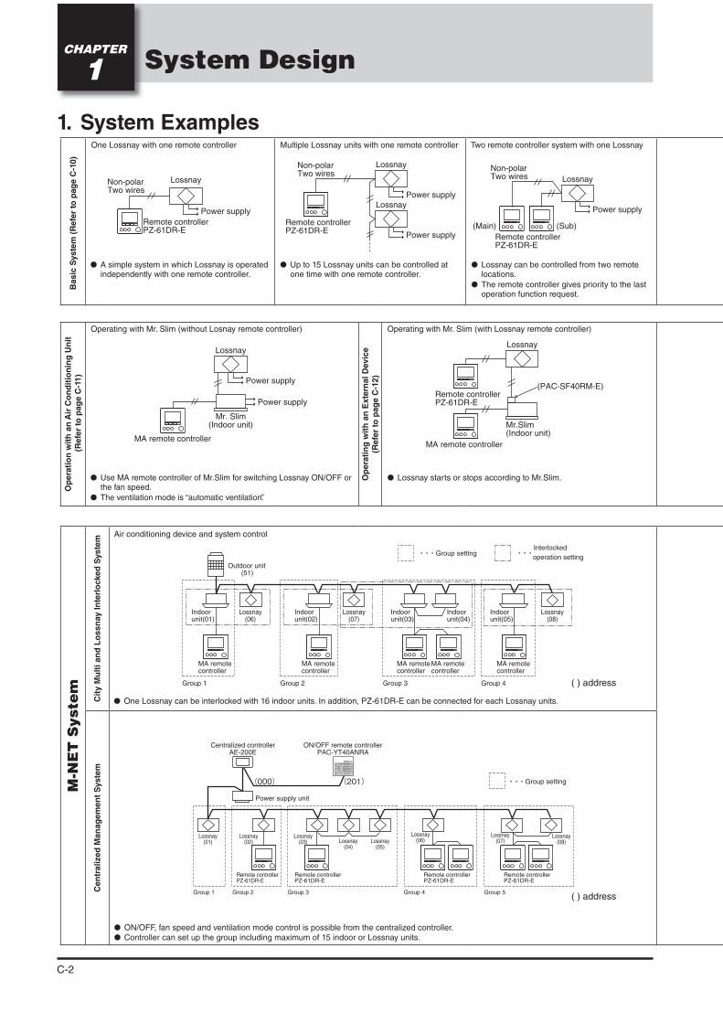
Operating with Mr. Slim (with Lossnay remote controller)
Lossnay starts or stops according to Mr.Slim.
One Lossnay with one remote controller
A simple system in which Lossnay is operated independently with one remote controller.
Multiple Lossnay units with one remote controller
Up to 15 Lossnay units can be controlled at one time with one remote controller.
Two remote controller system with one Lossnay
Lossnay can be controlled from two remote locations.
The remote controller gives priority to the last operation function request.
Operating with Mr. Slim (without Losnay remote controller)
Use MA remote controller of Mr.Slim for switching Lossnay ON/OFF or the fan speed.
The ventilation mode is “automatic ventilation”.
Lossnay
Remote controllerPZ-61DR-E
Power supply
Non-polar Two wires
Lossnay
Power supply
Lossnay
Power supply
Non-polar Two wires
Remote controllerPZ-61DR-E
Lossnay
Power supply
Non-polar Two wires
Remote controllerPZ-61DR-E
(Sub)(Main)
Air conditioning device and system control
Outdoor unit (51)
Indoor unit(01)
Indoor unit(02)
Indoor unit(03)
Indoor unit(04)
Indoor unit(05)
Lossnay(06)
Lossnay(07)
Lossnay(08)
MA remote controller
MA remote controller
MA remote controller
MA remote controller
MA remote controller
Group 1 Group 2 Group 3 Group 4
Group settingInterlocked
operation setting
ON/OFF, fan speed and ventilation mode control is possible from the centralized controller. Controller can set up the group including maximum of 15 indoor or Lossnay units.
Lossnay(01)
Lossnay(02)
Lossnay(03) Lossnay
(04)
Lossnay(06)
Lossnay(07)
Lossnay(08)Lossnay
(05)
ON/OFF remote controller PAC-YT40ANRA
Power supply unit
Remote controllerPZ-61DR-E
Remote controllerPZ-61DR-E
Remote controllerPZ-61DR-E
Remote controllerPZ-61DR-E
Group 1 Group 2 Group 3 Group 4 Group 5
Group setting
Centralized controllerAE-200E
(000) (201)
Lossnay
Power supply
Power supply
Mr. Slim(Indoor unit)
MA remote controller
Lossnay
Mr.Slim(Indoor unit)
(PAC-SF40RM-E)Remote controllerPZ-61DR-E
MA remote controller
One Lossnay can be interlocked with 16 indoor units. In addition, PZ-61DR-E can be connected for each Lossnay units.
1. System Examples
( ) address
( ) address
C-3
CHAPTER 1 System Design / 1. System Examples
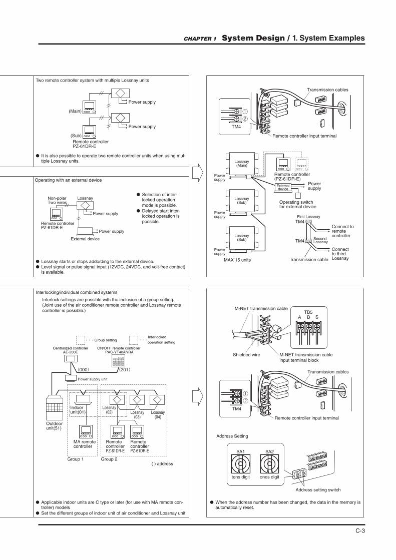
Two remote controller system with multiple Lossnay units
It is also possible to operate two remote controller units when using mul-tiple Lossnay units.
Power supply
Power supply
Remote controllerPZ-61DR-E
(Sub)
(Main)
Interlocking/individual combined systems
Interlock settings are possible with the inclusion of a group setting.(Joint use of the air conditioner remote controller and Lossnay remote controller is possible.)
Applicable indoor units are C type or later (for use with MA remote con-troller) models
Set the different groups of indoor unit of air conditioner and Lossnay unit.
When the address number has been changed, the data in the memory is automatically reset.
Indoor unit(01)
Lossnay(02) Lossnay
(03)Lossnay
(04)
(000) (201)
Group 1 Group 2
MA remote controller
Remote controllerPZ-61DR-E
Remote controllerPZ-61DR-E
Outdoor unit(51)
Group settingInterlocked
operation setting
ON/OFF remote controller PAC-YT40ANRA
Power supply unit
Centralized controllerAE-200E
Remote controller input terminal
Transmission cables
TM4
Lossnay(Main)
Remote controller(PZ-61DR-E)
Powersupply
Operating switchfor external device
MAX 15 units
Powersupply
Connect toremotecontroller
Connectto thirdLossnay
21
21
Transmission cable
First Lossnay
SecondLossnay
TM4
TM4
Lossnay(Sub)
Powersupply
Lossnay(Sub)
Powersupply
Externaldevice
Shielded wire M-NET transmission cable
input terminal block
M-NET transmission cable
Remote controller input terminal
Transmission cables
TM4
SBATB5
Address setting switch
SA1 SA2
tens digit ones digit
Address Setting
( ) address
Operating with an external device
Lossnay starts or stops addording to the external device. Level signal or pulse signal input (12VDC, 24VDC, and volt-free contact) is available.
Lossnay
Power supply
Power supply
External device
Non-polar Two wires
Remote controllerPZ-61DR-E
Selection of inter-locked operation mode is possible.
Delayed start inter-locked operation is possible.
C-4
2. Function list and outline
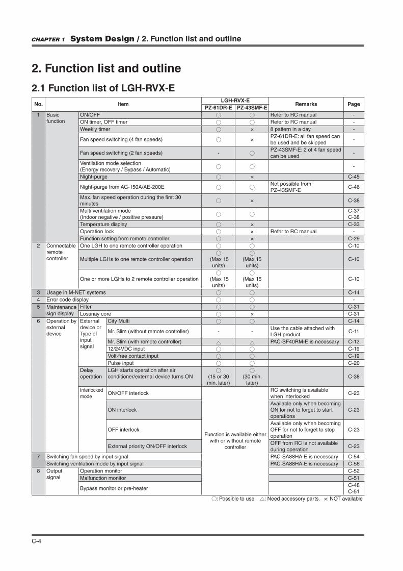
2.1 Function list of LGH-RVX-E
No. ItemLGH-RVX-E
Remarks PagePZ-61DR-E PZ-43SMF-E
1 Basic function
ON/OFF Refer to RC manual -
ON timer, OFF timer Refer to RC manual -
Weekly timer × 8 pattern in a day -
Fan speed switching (4 fan speeds) ×PZ-61DR-E: all fan speed can be used and be skipped
-
Fan speed switching (2 fan speeds) -PZ-43SMF-E: 2 of 4 fan speed can be used
-
Ventilation mode selection (Energy recovery / Bypass / Automatic)
-
Night-purge × C-45
Night-purge from AG-150A/AE-200ENot possible from PZ-43SMF-E
C-46
Max. fan speed operation during the "rst 30 minutes
× C-38
Multi ventilation mode (Indoor negative / positive pressure)
C-37C-38
Temperature display × C-33
Operation lock × Refer to RC manual -
Function setting from remote controller × C-29
2 Connectableremotecontroller
One LGH to one remote controller operation C-10
Multiple LGHs to one remote controller operation (Max 15 units)
(Max 15 units)
C-10
One or more LGHs to 2 remote controller operation (Max 15 units)
(Max 15 units)
C-10
3 Usage in M-NET systems C-14
4 Error code display -
5 Maintenancesign display
Filter C-31
Lossnay core × C-31
6 Operation by external device
External device or Type of input signal
City Multi C-14
Mr. Slim (without remote controller) - -Use the cable attached with LGH product
C-11
Mr. Slim (with remote controller) PAC-SF40RM-E is necessary C-12
12/24VDC input C-19
Volt-free contact input C-19
Pulse input C-20
Delay operation
LGH starts operation after air conditioner/external device turns ON (15 or 30
min. later)
(30 min.
later)C-38
Interlocked mode
ON/OFF interlock
Function is available either with or without remote
controller
RC switching is available when interlocked
C-23
ON interlockAvailable only when becoming ON for not to forget to start operations
C-23
OFF interlockAvailable only when becoming OFF for not to forget to stop operation
C-23
External priority ON/OFF interlockOFF from RC is not available during operation
C-23
7 Switching fan speed by input signal PAC-SA88HA-E is necessary C-54
Switching ventilation mode by input signal PAC-SA88HA-E is necessary C-56
8 Output signal
Operation monitor C-52
Malfunction monitor C-51
Bypass monitor or pre-heaterC-48C-51
: Possible to use. : Need accessory parts. ×: NOT available
CHAPTER 1 System Design / 2. Function list and outline
C-5
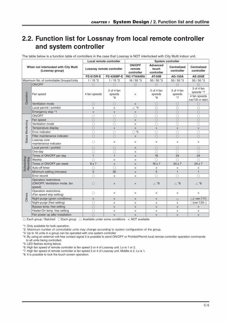
2.2. Function list for Lossnay from local remote controller and system controller
The table below is a function table of controllers in the case that Lossnay is NOT interlocked with City Multi indoor unit.
When not interlocked with City Multi (Lossnay group)
Local remote controller System controller
Lossnay remote controllerON/OFF remote
controller
Advanced touch
controller
Centralized controller
Centralized controller
PZ-61DR-E PZ-43SMF-E PAC-YT40ANRA AT-50B AG-150A AE-200E
Maximum No. of controllable Groups/Units 1 / 15 *2 1 / 15 *2 16 / 50 *3 50 / 50 *3 50 / 50 *3 50 / 50 *3
Op
era
tio
n
ON/OFF
Fan speed 4 fan speeds2 of 4 fan speeds
*6×
2 of 4 fan speeds
*6
3 of 4 fan speeds
*7
3 of 4 fan speeds *7
4 fan speeds (ver7.30 or later)
Ventilation mode ×
Local permit / prohibit × × *4
Emergency stop *1 × × ×
Sta
tus M
on
itori
ng
ON/OFF
Fan speed ×
Ventilation mode ×
Temperature display × × × × ×
Error indicator *5
Filter maintenance indicator ×
Lossnay core maintenance indicator
× × × × ×
Local permit / prohibit ×
Sch
ed
ulin
g/
Re
co
rdin
g
One-day ×
Times of ON/OFF per day 1 1 × 16 24 24
Weekly × ×
Times of ON/OFF per week 8 x 7 × × 16 x 7 24 x 7 24 x 7
Auto-off timer × × × ×
Minimum setting (minutes) 5 30 × 5 1 1
Error record × ×
Oth
ers
Operation restrictions (ON/OFF, Ventilation mode, fan speed)
× × *8 *8 *8
Operation restrictions (Fan speed skip setting)
× × × × ×
Night-purge (given conditions) × × × × (~ver.7.11)
Night-purge (free setting) × × × × (ver.7.20~)
Bypass temp. free setting × × × × ×
Heater-On temp. free setting × × × × ×
Fan power up after installation × × × × ×
: Each group / Batched :Each group : Available under some conditions ×: NOT available
*1: Only available for bulk operation.*2: Maximum number of controllable units may change according to system configuration of the group.*3: Up to 16 units in a group can be operated with one system controller*4: By using an external volt-free contact signal it is possible to send ON/OFF or Prohibit/Permit local remote controller operation commands
to all units being controlled.*5: LED #ashes during failure.*6: High fan speed of remote controller is fan speed 3 or 4 of Lossnay unit. Lo is 1 or 2.*7: High fan speed of remote controller is fan speed 3 or 4 of Lossnay unit. Middle is 2. Lo is 1.*8: It is possible to lock the touch screen operation.
CHAPTER 1 System Design / 2. Function list and outline
C-6
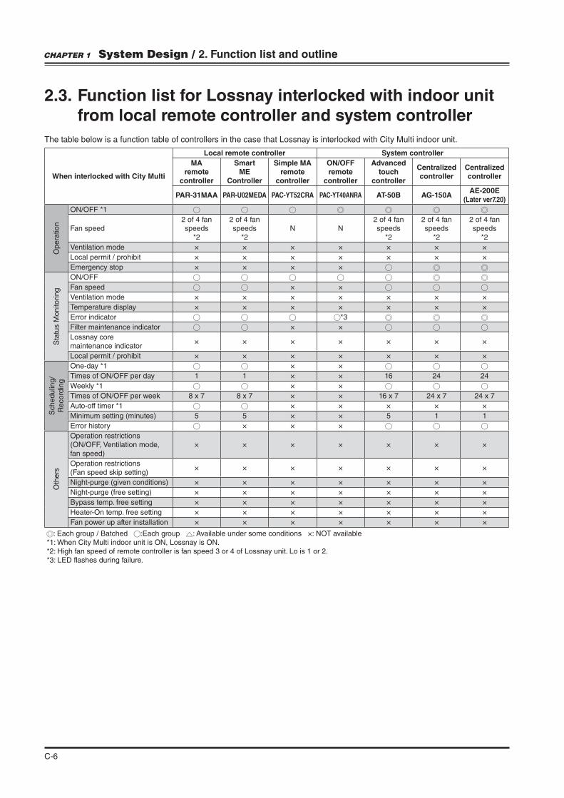
When interlocked with City Multi
Local remote controller System controller
MA remote
controller
Smart ME
Controller
Simple MA remote
controller
ON/OFF remote
controller
Advanced touch
controller
Centralized controller
Centralized controller
PAR-31MAA PAR-U02MEDA PAC-YT52CRA PAC-YT40ANRA AT-50B AG-150AAE-200E
(Later ver7.20)
Op
era
tio
n
ON/OFF *1
Fan speed2 of 4 fan speeds
*2
2 of 4 fan speeds
*2N N
2 of 4 fan speeds
*2
2 of 4 fan speeds
*2
2 of 4 fan speeds
*2
Ventilation mode × × × × × × ×
Local permit / prohibit × × × × × × ×
Emergency stop × × × ×
Sta
tus M
on
itori
ng
ON/OFF
Fan speed × ×
Ventilation mode × × × × × × ×
Temperature display × × × × × × ×
Error indicator *3
Filter maintenance indicator × ×
Lossnay core maintenance indicator
× × × × × × ×
Local permit / prohibit × × × × × × ×
Sch
ed
ulin
g/
Re
co
rdin
g
One-day *1 × ×
Times of ON/OFF per day 1 1 × × 16 24 24
Weekly *1 × ×
Times of ON/OFF per week 8 x 7 8 x 7 × × 16 x 7 24 x 7 24 x 7
Auto-off timer *1 × × × × ×
Minimum setting (minutes) 5 5 × × 5 1 1
Error history × × ×
Oth
ers
Operation restrictions (ON/OFF, Ventilation mode, fan speed)
× × × × × × ×
Operation restrictions (Fan speed skip setting)
× × × × × × ×
Night-purge (given conditions) × × × × × × ×
Night-purge (free setting) × × × × × × ×
Bypass temp. free setting × × × × × × ×
Heater-On temp. free setting × × × × × × ×
Fan power up after installation × × × × × × ×
: Each group / Batched :Each group : Available under some conditions ×: NOT available*1: When City Multi indoor unit is ON, Lossnay is ON.*2: High fan speed of remote controller is fan speed 3 or 4 of Lossnay unit. Lo is 1 or 2.*3: LED #ashes during failure.
2.3. Function list for Lossnay interlocked with indoor unit from local remote controller and system controller
The table below is a function table of controllers in the case that Lossnay is interlocked with City Multi indoor unit.
CHAPTER 1 System Design / 2. Function list and outline

C-7
3. System structure
3.1 Notes/Cautions when system con!guration
3.1.1 Basic system Operation by local remote controller (Refer to page C-10)
Following local remote controllers can be used.
(1) Different model remote controllers cannot be used together in a group.
(2) Maximum 2 remote controllers can be connected in a group.
(3) When two PZ-61DR-E are used in a group, set one remote controller as main and the other as sub. (Refer to installation manual of PZ-61DR-E.)
(4) Adequate remote controller cableSecurely connect the transmission cable from the remote controller to the terminal block (TM4 ). (No polarity)
.m.
3.1.2 Group setting
Lossnay units set in a group can be operated at the same time from local remote controller.
(1) It is not possible to set Lossnay and Indoor unit of air conditioner in a group.
(2) When using local remote controller or interlocking with external device,) each other become the same group.
terminal bock (TM4 ) becomes the same group.
(3) When connected to MELANS*, without Lossnay remote controller and not interlocked with City Multi indoor units or any external device.
) is not necessary. However, in order to perform Night-purge function by using the system controller (AE-200E), connect them to each other.
*MELANS : MITSUBISHI ELECTRIC's Air-conditioner Network System
3.1.3 Interlocking with City Multi(Refer to page C-14)
When Lossnay and City Multi are connected to MELANS, it is possible to switch Lossnay “ON/OFF” and “High/Low” operation from the indoor unit remote controller.Ventilation mode is "xed to Automatic mode.
(1) One Lossnay unit can be interlocked with up to 16 indoor units.
(2) Perform interlock settings at the system controller or local remote controller of City Multi indoor unit.
(3) The Lossnay remote controller (PZ-61DR-E, PZ-43SMF-E) can be used.
(4) It is not possible to be interlocked together with Mr. Slim or external device.
(5) When interlocking City Multi indoor unit and Lossnay,
) of each Lossnay unit.
(6) Following interlock mode are NOT available.(Refer to page C-23)
Wire type 2 core sheathed cable
Wire diameter 0.3mm2
Max overall length between Lossnayand remote controller
200m
CHAPTER 1 System Design / 3. System structure
C-8
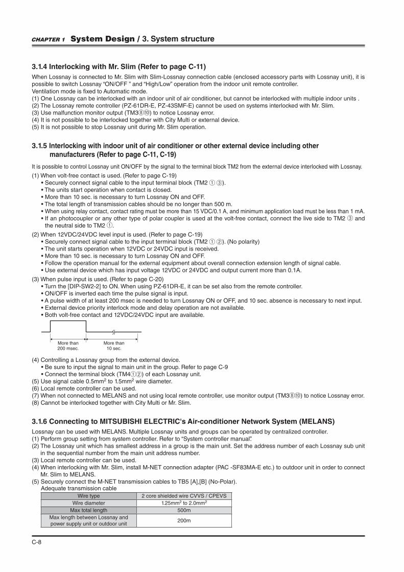
3.1.4 Interlocking with Mr. Slim (Refer to page C-11)
When Lossnay is connected to Mr. Slim with Slim-Lossnay connection cable (enclosed accessory parts with Lossnay unit), it is possible to switch Lossnay “ON/OFF ” and “High/Low” operation from the indoor unit remote controller.
Ventilation mode is "xed to Automatic mode.(1) One Lossnay can be interlocked with an indoor unit of air conditioner, but cannot be interlocked with multiple indoor units .(2) The Lossnay remote controller (PZ-61DR-E, PZ-43SMF-E) cannot be used on systems interlocked with Mr. Slim.(3) Use malfunction monitor output (TM3 ) to notice Lossnay error.(4) It is not possible to be interlocked together with City Multi or external device.(5) It is not possible to stop Lossnay unit during Mr. Slim operation.
3.1.5 Interlocking with indoor unit of air conditioner or other external device including other manufacturers (Refer to page C-11, C-19)
It is possible to control Lossnay unit ON/OFF by the signal to the terminal block TM2 from the external device interlocked with Lossnay.
(1) When volt-free contact is used. (Refer to page C-19) ).
When using relay contact, contact rating must be more than 15 VDC/0.1 A, and minimum application load must be less than 1 mA. and
the neutral side to TM2 .
(2) When 12VDC/24VDC level input is used. (Refer to page C-19) ). (No polarity)
(3) When pulse input is used. (Refer to page C-20)
(4) Controlling a Lossnay group from the external device.
) of each Lossnay unit.(5) Use signal cable 0.5mm2 to 1.5mm2 wire diameter.(6) Local remote controller can be used.(7) When not connected to MELANS and not using local remote controller, use monitor output (TM3 ) to notice Lossnay error.(8) Cannot be interlocked together with City Multi or Mr. Slim.
3.1.6 Connecting to MITSUBISHI ELECTRIC's Air-conditioner Network System (MELANS)
Lossnay can be used with MELANS. Multiple Lossnay units and groups can be operated by centralized controller.(1) Perform group setting from system controller. Refer to “System controller manual”.(2) The Lossnay unit which has smallest address in a group is the main unit. Set the address number of each Lossnay sub unit
in the sequential number from the main unit address number.(3) Local remote controller can be used.(4) When interlocking with Mr. Slim, install M-NET connection adapter (PAC -SF83MA-E etc.) to outdoor unit in order to connect
Mr. Slim to MELANS.
More than200 msec.
More than10 sec.
Wire type 2 core shielded wire CVVS / CPEVS
Wire diameter 1.25mm2 to 2.0mm2
Max total length 500m
Max length between Lossnay andpower supply unit or outdoor unit
200m
Adequate transmission cable
CHAPTER 1 System Design / 3. System structure
C-9
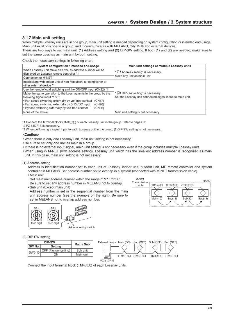
3.1.7 Main unit settingWhen multiple Lossnay units are in one group, main unit setting is needed depending on system con"guration or intended end-usage.Main unit exist only one in a group, and it communicates with MELANS, City Multi and external devices.There are two ways to set main unit, (1) Address setting and (2) DIP-SW setting. If both (1) and (2) are needed, make sure to
set the same Lossnay as main unit by both setting.
Check the necessary settings in following chart.
(1) Address settingAddress is identi"cation number set to each unit of Lossnay, indoor unit, outdoor unit, ME remote controller and system controller in MELANS. Set address number not to overlap in a system (connected with M-NET transmission cable).
Set main unit address number within the range of “01” to “50” .Be sure to set any address number in MELANS not to overlap.
Address number is set in the sequential number from the main unit address number (see the example on the right). Be sure to set in MELANS not to overlap address number.
(2) DIP-SW setting
Connect the input terminal block (TM4 ) of each Lossnay units.
System configuration / Intended end-usage Main unit settings of multiple Lossnay units
When Lossnay unit make an error, its address number will be displayed on Lossnay remote controller *1
“ (1) Address setting” is necessary.
Make any unit as main unit.Connection to M-NET
Interlocking with indoor unit of non-Mitsubishi air conditioner or other external device *1
“ (2) DIP-SW setting” is necessary.
Set the Lossnay unit connected signal input as main unit.
Use the remote/local switching and the ON/OFF input (CN32) *1
Make the same operation to the Lossnay units in the group by the following signal input *1*2*3
None of the above Main unit setting is not necessary.
*1 Connect the terminal block (TM4 ) of each Lossnay unit in the group. Refer to page C-3
*2 PZ-61DR-E is necessary.*3 When performing a signal input to each Lossnay unit in the group, (2)DIP-SW setting is not necessary.
M-NETTransmission
cable (TB5 )
Main(10) Sub(11) Sub(12) Sub(13)
1group
(TB5 ) (TB5 )
(TM4 )
Main (ON) Sub (OFF) Sub (OFF) Sub (OFF)
(TM4 ) (TM4 ) (TM4 )
PZ-61DR-E
External device
Address setting switch
SA1 SA2
tens digit ones digit
CHAPTER 1 System Design / 3. System structure
<Caution>
unit. In this case, main unit setting is not necessary.
DIP-SWMain / Sub
SW No. Setting
SW5-10OFF (Factory setting) Sub unit
ON Main unit
C-10
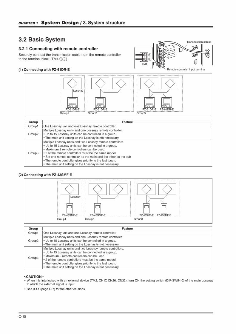
3.2 Basic System
3.2.1 Connecting with remote controller
Securely connect the transmission cable from the remote controllerto the terminal block (TM4 ).
(1) Connecting with PZ-61DR-E
(2) Connecting with PZ-43SMF-E
Remote controller input terminal
Transmission cables
TM4
Group1
Lossnay
Group2 Group3
PZ-61DR-E PZ-61DR-E PZ-61DR-E PZ-61DR-E
Lossnay
PZ-43SMF-E PZ-43SMF-E PZ-43SMF-E PZ-43SMF-E
Group1 Group2 Group3
Group Feature
Group1 One Lossnay unit and one Lossnay remote controller.
Group2Multiple Lossnay units and one Lossnay remote controller.
Group3
Multiple Lossnay units and two Lossnay remote controllers.
Group Feature
Group1 One Lossnay unit and one Lossnay remote controller.
Group2Multiple Lossnay units and one Lossnay remote controller.
Group3
Multiple Lossnay units and two Lossnay remote controllers.
<CAUTION>
to which the external signal is input.
CHAPTER 1 System Design / 3. System structure

C-11
3.3 Interlocking with Mr. Slim
3.3.1 Connecting with Slim-Lossnay connection cable
<Operation>
(1) Interlocking operation
“High” is fan speed 4 and “Low” is fan speed 2 at the factory setting. They can be changed. (Refer to page C-40)(2) Individual operation
SELECT button.
F3 button to go through ventilation setting options in order of “High”, “Low” and “Off”.
Slim-Lossnay connection cable
(Enclosed accessory parts with Lossnay unit)
MA remote controller
LossnayMr. Slim Indoor unit
Maximum 500 m
Lossnay external
control input
(TM2)
Slim-Lossnay connection cable
CN2L
Mr. Slim (Indoor unit)
PCB
<Feature>
unit.
<Caution>
. (Refer to page C-51)
< Wiring >
of Lossnay PCB.
Ensure that all connections are secure and that the appropriate insulation is provided.Use extension cable sheathed PVC cable or cable 0.5 mm2 to 0.75 mm2.Always separate the power supply cable and the Slim-Lossnay connection cable by 5 cm or more to prevent the unit frommalfunction.
CHAPTER 1 System Design / 3. System structure
C-12
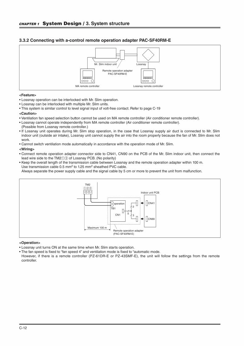
3.3.2 Connecting with a-control remote operation adapter PAC-SF40RM-E
Lossnay remote controller
Mr. Slim indoor unit
MA remote controller
Remote operation adapter
PAC-SF40RM-E
Lossnay
<Feature>
<Caution>
(Possible from Lossnay remote controller.)
indoor unit (outside air intake), Lossnay unit cannot supply the air into the room properly because the fan of Mr. Slim does not work.
<Wiring>
lead wire side to the TM2 of Lossnay PCB. (No polarity)
Use transmission cable 0.5 mm2 to 1.25 mm2 sheathed PVC cable.Always separate the power supply cable and the signal cable by 5 cm or more to prevent the unit from malfunction.
<Operation>
However, if there is a remote controller (PZ-61DR-E or PZ-43SMF-E), the unit will follow the settings from the remote controller.
TB1
CN15
2
3
CN41
CN90
TM2
Indoor unit PCB
Maximum 100 mRemote operation adapter
(PAC-SF40RM-E)
operation
CHAPTER 1 System Design / 3. System structure
C-13
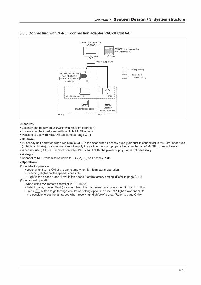
3.3.3 Connecting with M-NET connection adapter PAC-SF83MA-E
(01)
(02)
(000) (201)
ON/OFF remote controller
PAC-YT40ANRA
Centralized controller
AE-200E
Mr. Slim outdoor unit
PAC-SF83MA-E
or PAC-SJ19MA-E
is installed
Mr. Slim indoor unit
MA remote controller
Group1 Group2
Power supply unit
Lossnay
remote controller
Group setting
Interlocked
operation setting
<Feature>
<Caution>
(outside air intake), Lossnay unit cannot supply the air into the room properly because the fan of Mr. Slim does not work.
<Wiring>
<Operation>
(1) Interlock operation
“High” is fan speed 4 and “Low” is fan speed 2 at the factory setting. (Refer to page C-40)(2) Individual operation
SELECT button.F3 button to go through ventilation setting options in order of “High”, “Low” and “Off”.
It is possible to set the fan speed when receiving “High/Low” signal. (Refer to page C-40)
CHAPTER 1 System Design / 3. System structure

C-14
3.4 M-NET system
3.4.1 Wiring
.
Type: Shielded wire (CVVS/CPEVS) Wire diameter: 1.25 mm2 to 2.0 mm2 Maximum torque: 0.5 N·m
3.4.2 Address setting
Address setting is required when connecting to City Multi and MELANS. Refer to page C-9
Shielded wire M-NET transmission cable
input terminal block
M-NET transmission cable
SBATB5
(01) (02) (03) (04) (05)
(000) (201)
( ) address
Group settingCentralized controller
AE-200E
ON/OFF remote controller
PAC-YT40ANRA
Power supply unit
Lossnay
remote controller
Lossnay Lossnay Lossnay Lossnay Lossnay
Lossnay
remote controller
Lossnay
remote controller
Group1 Group2 Group3
3.4.3 Lossnay system
<Feature>
<Caution>
<System example 1>
Group Feature
Group1
One Lossnay unit and one Lossnay remote controller.Lossnay unit can be controlled by Lossnay remote controller.All of Lossnay units can be controlled by centralized controller and ON/OFF remote controller, and each group can be controlled individually.
Group2
Multiple Lossnay units and two Lossnay remote controllers.Lossnay can be controlled by Lossnay remote controller.Up to 2 Lossnay remote controllers can be used in a group and they must be the same model.When 2 of PZ-61DR-E are used, one of them must be “sub” setting. For details, refer to the installation manual of PZ-61DR-E.When 2 Lossnay remote controllers are used, the last touch has a priority.All of Lossnay units can be controlled by centralized controller and ON/OFF remote controller, and each group can be controlled individually.Up to 15 Lossnay units can be connected in a group.
It is necessary to connect the terminal TM4 of each Lossnay units.
Group3
Multiple Lossnay units without remote controllers.All of Lossnay units can be controlled by centralized controller and ON/OFF remote controller, and each group can be controlled individually.
Up to 16 Lossnay units can be connected in a group. It is NOT necessary to connect the terminal TM4 of each Lossnay
unit. (It is necessary to connect the terminal TM4 of each Lossnay unit when the Night-purge function is used by a centralized controller.)
CHAPTER 1 System Design / 3. System structure

C-15
(06)
(000) (201)
Lossnay (07)Lossnay (08)Lossnay (09)Lossnay
Power supply unit
Lossnay
remote controller
Lossnay
remote controller
Group settingInterlocked
operation settingCentralized controller
AE-200E
ON/OFF remote controller
PAC-YT40ANRA
Indoor unit
Group 1 Group 2 Group 3 Group 4 Group 5 Group 6 Group 7
MA remote controller
MA remote controller
MA remote controller
MA remote controller
Outdoor unit(51)
(01) Indoor unit
(02) Indoor unit Indoor
unit
Indoor unit
(03) (04) (05)
( ) address
3.4.4 City Multi and Lossnay interlocked system
<Feature>
<Caution>
<System example 2>
Group Feature
Group2
One Lossnay unit which are interlocked to indoor unit of group 1. Operation of Lossnay unit can be performed by MA remote controller. All of Lossnay units can be controlled by centralized controller and ON/OFF remote controller, and each group can be controlled individually.
Group4
One Lossnay unit which is interlocked to multiple indoor units. Operation of Lossnay unit can be performed by Lossnay remote controller and 2 MA remote controllers. The last touch of Lossnay remote controller or MA remote controller has a priority. All of Lossnay units can be controlled by centralized controller and ON/OFF remote controller, and each group can be controlled individually. One Lossnay unit can be interlocked to up to 16 indoor units.
Group7
Multiple Lossnay units which are interlocked to indoor unit of group 6. Operation of Lossnay unit can be performed by 2 Lossnay remote controllers and MA remote controller. The last touch of Lossnay remote controller or MA remote controller has a priority. Up to 2 Lossnay remote controllers can be used in a group and they must be the same model. When 2 PZ-61DR-Es are used, one of them must be done “sub” setting. For details, refer to the installation manual of PZ-61DR-E. All of Lossnay units can be controlled by centralized controller and ON/OFF remote controller, and each group can be controlled individually. Up to 15 Lossnay units can be connected in a group.
It is necessary to connect the terminal TM4 of each Lossnay units.
CHAPTER 1 System Design / 3. System structure

C-16
HUB
System No.1
System No.2
HUB
M-NET
PZ-61DR-E
PZ-43SMF-E
M-NET
M-NET M-NET
M-NET
PZ-61DR-E
PZ-61DR-EPZ-61DR-E
PZ-61DR-E
PZ-43SMF-E
maximum 50 units
Each unit can control up to a total of 2000 indoor, Lossnay, and other units.
AE-200E unit can control up to a total of 200 indoor, Lossnay, and other units (when used with three AE-50E.
maximum 50 units
maximum 50 units
M-NET M-NET
PZ-61DR-E
maximum 50 units
maximum 50 units
Centralized controllerAE-200E
Lossnay
Lossnay Lossnay Lossnay
Lossnay
Lossnay Lossnay Lossnay
Lossnay Lossnay
Indoor unit
MA remote controller
Outdoor unit
PC for Centralized control
(TG-2000A)
Centralized
controller
AE-200E
Centralized
controller
AE-50E
Centralized
controller
AE-50E
Centralized
controller
AE-50E
LossnayIndoor unit
MA remote controller
Outdoor unit
3.4.5 System con!guration of more than 50 units (Lossnay and indoor units)
<Feature>
controlled from one AE-200E connected with three AE-50E.
<System example 3>
Group Feature
All All of indoor and Lossnay units can be controlled by the PC for centralized control.
System No. 1
All units of system No.1 can be controlled by centralized controller AE-200E in system No. 1.Each indoor and Lossnay unit can be controlled by each local remote controller.
System No. 2
All units of system No.2 can be controlled by centralized controller AE-200E in system No. 2.Lossnay unit can be controlled by Lossnay remote controller.
CHAPTER 1 System Design / 3. System structure
C-17
(01)(03)
(02)
MAC-333IF-E MAC-333IF-E
(000) (201)
Lossnay
Power supply unit
Room air-conditioner Room air-conditioner
Group settingInterlocked
operation settingCentralized controller
AE-200E
ON/OFF remote controller
PAC-YT40ANRA
Group 1 Group 2Group 3
MA remote controller
MA remote controller
( ) address
Lossnay
remote controller
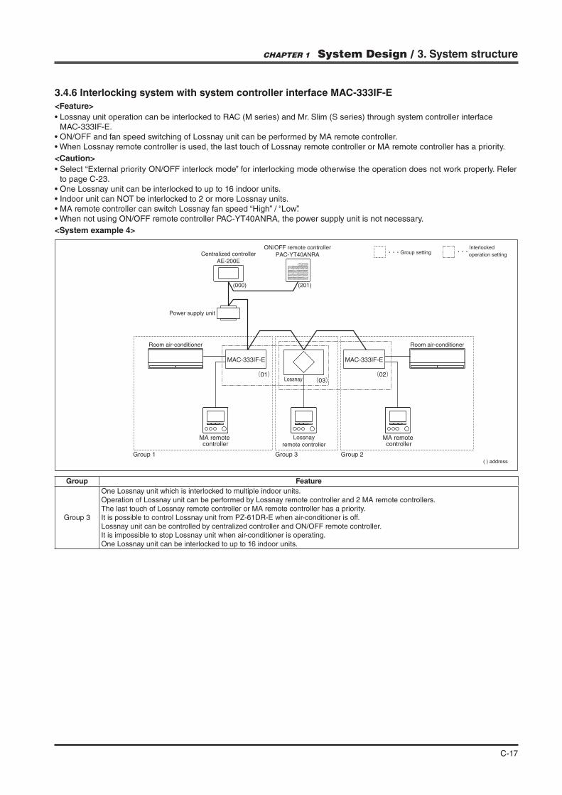
3.4.6 Interlocking system with system controller interface MAC-333IF-E
<Feature>
MAC-333IF-E.
<Caution>
to page C-23.
<System example 4>
Group Feature
Group 3
One Lossnay unit which is interlocked to multiple indoor units.Operation of Lossnay unit can be performed by Lossnay remote controller and 2 MA remote controllers.The last touch of Lossnay remote controller or MA remote controller has a priority.It is possible to control Lossnay unit from PZ-61DR-E when air-conditioner is off.Lossnay unit can be controlled by centralized controller and ON/OFF remote controller.It is impossible to stop Lossnay unit when air-conditioner is operating.One Lossnay unit can be interlocked to up to 16 indoor units.
CHAPTER 1 System Design / 3. System structure

C-18
Lossnay
Lossnay
remote controller
Group setting
Group 1 Group 2
Interlock InterlockInterlock
Group 3
MA remote controller
MA remote controller
MA remote controller
Outdoor unit
Indoor unit
(00) (00)
(00)
(00) (00)
( ) address
3.4.7 Automatic-address-start-up function
<Feature>
unit.There is indoor unit(s) in a system.There is only one Lossnay unit in a system.There are NO outdoor-air processing units (GUF series) in a system.
<How to use Automatic-address-start-up function>
<System example 4>
<Function explanation>
CHAPTER 1 System Design / 3. System structure
C-19
More than
10sec
Minimun 10sec. absence
to the next ON
ON
OFF
Lossnay
Level
signal
OFF ON
Contact closed
Volt-free contact 24VDC or 12VDC
Contact opened
24VDC or 12VDC
0VDC
OFF OFF ON OFFLossnay
Level
signal
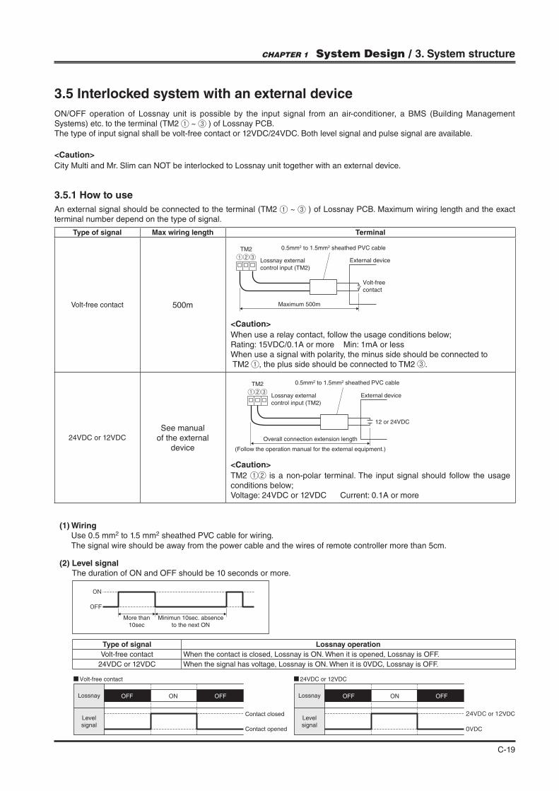
3.5.1 How to use
An external signal should be connected to the terminal (TM2 ~ ) of Lossnay PCB. Maximum wiring length and the exact terminal number depend on the type of signal.
3.5 Interlocked system with an external device
ON/OFF operation of Lossnay unit is possible by the input signal from an air-conditioner, a BMS (Building Management Systems) etc. to the terminal (TM2 ~ ) of Lossnay PCB.The type of input signal shall be volt-free contact or 12VDC/24VDC. Both level signal and pulse signal are available.
<Caution>
City Multi and Mr. Slim can NOT be interlocked to Lossnay unit together with an external device.
(1) Wiring Use 0.5 mm2 to 1.5 mm2 sheathed PVC cable for wiring.
The signal wire should be away from the power cable and the wires of remote controller more than 5cm.
(2) Level signal The duration of ON and OFF should be 10 seconds or more.
Type of signal Lossnay operation
Volt-free contact When the contact is closed, Lossnay is ON. When it is opened, Lossnay is OFF.
24VDC or 12VDC When the signal has voltage, Lossnay is ON. When it is 0VDC, Lossnay is OFF.
Type of signal Max wiring length Terminal
Volt-free contact 500m
Volt-free
contact
Maximum 500m
External device①②③TM2
Lossnay external
control input (TM2)
0.5mm2 to 1.5mm2 sheathed PVC cable
<Caution>
When use a relay contact, follow the usage conditions below;Rating: 15VDC/0.1A or more Min: 1mA or lessWhen use a signal with polarity, the minus side should be connected to TM2 , the plus side should be connected to TM2 .
24VDC or 12VDC
See manual
of the external
device
12 or 24VDC
Overall connection extension length
(Follow the operation manual for the external equipment.)
①②③TM2
External device
0.5mm2 to 1.5mm2 sheathed PVC cable
Lossnay external
control input (TM2)
<Caution>
TM2 is a non-polar terminal. The input signal should follow the usage conditions below;Voltage: 24VDC or 12VDC Current: 0.1A or more
CHAPTER 1 System Design / 3. System structure

C-20
(3) Pulse signal When using a pulse signal input, set the DIP-SW 2-2 ON or set the function No.28 by PZ-61DR-E. See the table below.
(4) Group control In the case that multiple Lossnay units are controlled by an input signal, follow the connection and setting below.
of each Lossnay units.
(5) Interlocked to multiple external devices When the input signal is level signal, one Lossnay unit can be interlocked to multiple external devices.
OFF.
The duration of ON should be 200 msec. or more and 10 sec. or more absence is necessary to the next pulse .
ON/OFF of Lossnay unit is inverted each time a pulse signal is inputted.
DIP-SW Setting check
PZ-61DR-E Setting check
Pulse input settingSW No. Setting Function No. Setting Data
SW2-2
- -
28
0(Factory setting)
DIP-SW priority
OFF (Factory setting)
1 NOT pulse input
ON 2 Pulse input
More than
200 msec.
Minimun 10sec. absence
to the next pulse
ON
OFF
Lossnay
Pulse
signal
Volt-free contact 24VDC or 12VDC
24VDC or 12VDC
0VDC
OFF OFF ONOFF ON OFFLossnay
Pulse
signal
Contact closed
Contact opened
Contact closed
Contact opened
Contact closed
Contact opened
Contact closed
Contact opened
OFF OFFONLossnay
No.1
external
device
No.2
external
device
No.3
external
device
<Caution>
In conditions of pulse input is set to ON, following functions are not available.
CHAPTER 1 System Design / 3. System structure

C-21
(6) Operation monitor output (Refer to page C-52) The ON/OFF status of Lossnay can be checked by the operation monitor output.When Lossnay unit is ON, the relay X15 of PCB (TM3 ) is closed. The operation monitor output follows the external input signal with maximum 200 msec delay.
(7) Malfunction monitor output (Refer to page C-51)When Lossnay unit is not connected to MELANS or Lossnay remote controller, the error monitor output function should be used to know the malfunction of Lossnay unit.When Lossnay unit has an error, the relay X14 of PCB (TM3 ) is closed.
External device
Power
External device operation switch
External device
Power
External device operation switch
External device
Power
External device operation switch
External device
Power
External device operation switch
Remote output component
500 m or less
External control input (TM2)
Lossnay
Non-Mitsubishi
air-conditioner
Lossnay Signal
Lossnay remote controller
3.5.2 Interlocked system with non-Mitsubishi air-conditioner
<Feature>
<Caution>
mode. Use malfunction monitor output function to notice Lossnay error.
CHAPTER 1 System Design / 3. System structure

C-22
3.5.3 Interlocked system with BMS (Building Management Systems)
3.5.4 Combination system of MELANS and external devices
<Feature>
For details, refer to page C-54.
<Caution>
mode. Use malfunction monitor output function to notice Lossnay error.
Lossnay
remote controller
Signal
BMS
Lossnay
Max 15 units per group
Main Sub Sub
(01) (02) (03) (04)(05)
Group1Group2 Group3
System controller
(201)
Non-Mitsubishi
air conditioner
Power supply unit
Lossnay
remote controller Control-equipment ( ) addressControl-equipment
Lossnay
remote controller
Group Feature
Group1
MELANS control Lossnay unit. Lossnay unit is interlocked with non-Mitsubishi air-conditioner.Lossnay unit turns ON/OFF by a signal from the air-conditioner.Lossnay unit can be controlled, ON/OFF or fan speed switching, by Lossnay remote controller or system controller individually.When an error occurs, the error number will appear on Lossnay remote controller and system controller.
Group2
MELANS control Lossnay unit. Lossnay unit is interlocked to a control-equipment.Lossnay unit turns ON/OFF by a signal from a control-equipment.Lossnay unit can be controlled, ON/OFF or fan speed switching, by Lossnay remote controller or system controller individually.When an error occurs, the error number will appear on Lossnay remote controller and system controller.
Group3
MELANS control Lossnay unit. Lossnay unit is interlocked to a control-equipment. Group 3 is an example as same as group 2 other than Lossnay remote controller.Lossnay unit turns ON/OFF by a signal from a control-equipment.Lossnay unit can be controlled, ON/OFF or fan speed switching, by system controller individually.When an error occurs, the error number will appear on system controller.
CHAPTER 1 System Design / 3. System structure
C-23
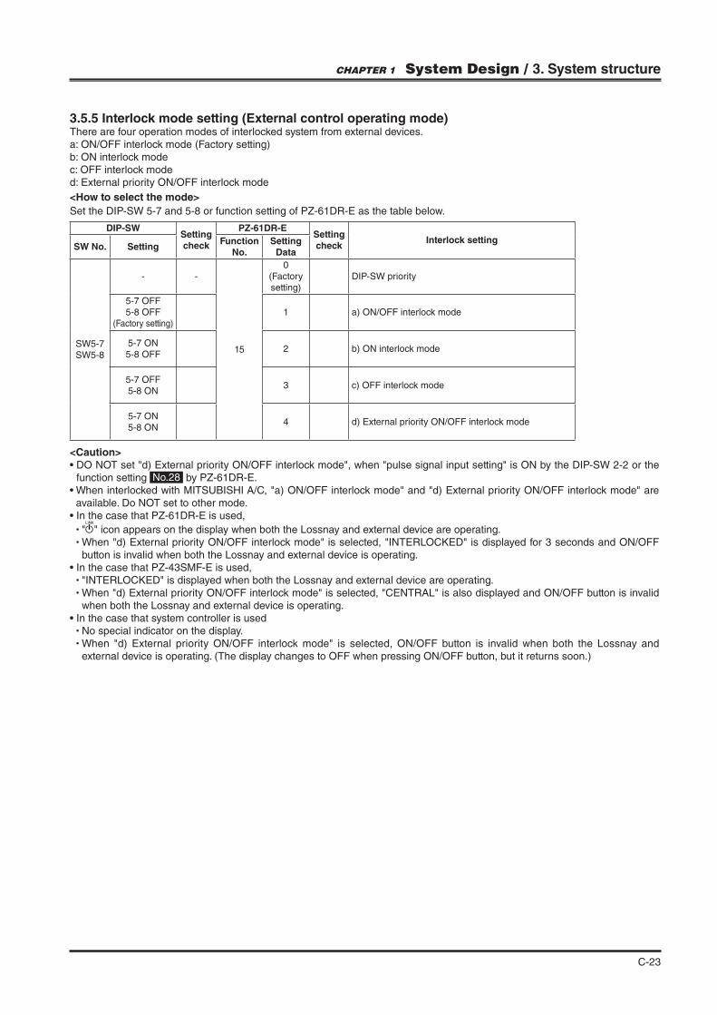
3.5.5 Interlock mode setting (External control operating mode)There are four operation modes of interlocked system from external devices.a: ON/OFF interlock mode (Factory setting)b: ON interlock modec: OFF interlock moded: External priority ON/OFF interlock mode
<How to select the mode>
Set the DIP-SW 5-7 and 5-8 or function setting of PZ-61DR-E as the table below.
DIP-SWSetting check
PZ-61DR-ESetting check
Interlock settingSW No. Setting
Function No.
Setting Data
SW5-7SW5-8
- -
15
0(Factory setting)
DIP-SW priority
5-7 OFF5-8 OFF
(Factory setting)1 a) ON/OFF interlock mode
5-7 ON5-8 OFF
2 b) ON interlock mode
5-7 OFF5-8 ON
3 c) OFF interlock mode
5-7 ON5-8 ON
4 d) External priority ON/OFF interlock mode
<Caution>
function setting No.28 by PZ-61DR-E.
available. Do NOT set to other mode.
button is invalid when both the Lossnay and external device is operating.
when both the Lossnay and external device is operating.
No special indicator on the display.
external device is operating. (The display changes to OFF when pressing ON/OFF button, but it returns soon.)
CHAPTER 1 System Design / 3. System structure

C-24
b) ON interlock modeLossnay unit turns ON externally.Lossnay unit does not turn OFF externally.Regardless of the signal of external device, Lossnay unit can be controlled by Lossnay remote controller and MELANS controller.Note; This mode is not available when Lossnay is interlocked with Mr.Slim or C/M indoor unit via TM2 ~ .
▽ ▼ ▼
▽▽ ▼▼ ▼
<“OFF” signal><“ON” signal>
ON ON
Lossnay unit
trurns ON
externally
Lossnay unit
does not turn
OFF externally
ON signal OFF signal
Non-Mitsubishi
air-conditioner
Non-Mitsubishi
air-conditioner
Lossnay Lossnay
<Pulse signal>
<Level signal> Remote controller[ON/OFF] buttonpressed
Lossnay unitoperation condition
External signal
Remote controller[ON/OFF] buttonpressed
Lossnay unitoperation condition
External signal
“ON” signal
“OFF” signal
ON OFF
▼OFF OFF
OFF OFF OFFON ON
ON ON ONOFF OFF OFFOFF
ON OFF OFFOFF ONON OFF
a) ON/OFF interlock mode (Factory setting)Lossnay unit turns ON externally.Lossnay unit turns OFF externally.Regardless of the signal of external device, Lossnay unit can be controlled by Lossnay remote controller and MELANS controller.
<Pulse signal>
▽ ▼ ▼
▽ ▽▼ ▼
<“OFF” signal><“ON” signal>
<Level signal>
Non-Mitsubishi
air-conditioner
Non-Mitsubishi
air-conditioner
ON signal
Lossnay
Lossnay unit
turns ON
externally
Remote controller[ON/OFF] buttonpressed
“ON” signal
“OFF” signal
OFF signal
Lossnay
Lossnay unit
turns OFF
externally
Lossnay unitoperation condition
External signal
Remote controller[ON/OFF] buttonpressed
Lossnay unitoperation condition
External signal
ON OFF OFF
ON OFF OFF ON
ON
ON OFF
OFF OFF OFF OFFON ON
ONOFF OFF OFFON ON OFF ON OFF
CHAPTER 1 System Design / 3. System structure
C-25
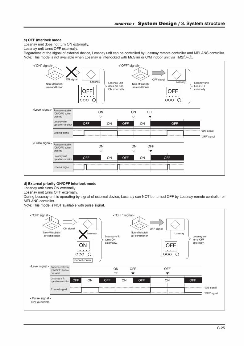
d) External priority ON/OFF interlock modeLossnay unit turns ON externally.Lossnay unit turns OFF externally.During Lossnay unit is operating by signal of external device, Lossnay can NOT be turned OFF by Lossnay remote controller or MELANS controller.Note; This mode is NOT available with pulse signal.
c) OFF interlock modeLossnay unit does not turn ON externally.Lossnay unit turns OFF externally.Regardless of the signal of external device, Lossnay unit can be controlled by Lossnay remote controller and MELANS controller.Note; This mode is not available when Lossnay is interlocked with Mr.Slim or C/M indoor unit via TM2 ~ .
▽ ▼ ▼
<”OFF” signal><”ON” signal>
ON signal OFF signal
Lossnay Lossnay
ON OFF
Lossnay unit
turns ON
externally.
Lossnay unit
turns OFF
externally.
Cannot control
<Level signal> Remote controller[ON/OFF] buttonpressed
Lossnay unitoperation condition
External signal “ON” signal
“OFF” signal
ON OFF OFF
ONOFF ONOFF ONOFF OFF
Non-Mitsubishi
air-conditioner
Non-Mitsubishi
air-conditioner
▽▽ ▼
▽▽ ▼
<“OFF” signal><“ON” signal>
Non-Mitsubishi
air-conditioner
Non-Mitsubishi
air-conditioner
ON signal OFF signal
Lossnay unit
turns OFF
externally
Lossnay unit
does not turn
ON externally
Lossnay Lossnay
<Pulse signal>
<Level signal> Remote controller[ON/OFF] buttonpressed
Lossnay unitoperation condition
External signal
Remote controller[ON/OFF] buttonpressed
Lossnay unitoperation condition
External signal
OFF OFF
ON ON OFF
ON ON OFF
ON ONOFF OFFOFF
ON ONOFF OFFOFF
“ON” signal
“OFF” signal
CHAPTER 1 System Design / 3. System structure
<Pulse signal>Not available
C-26
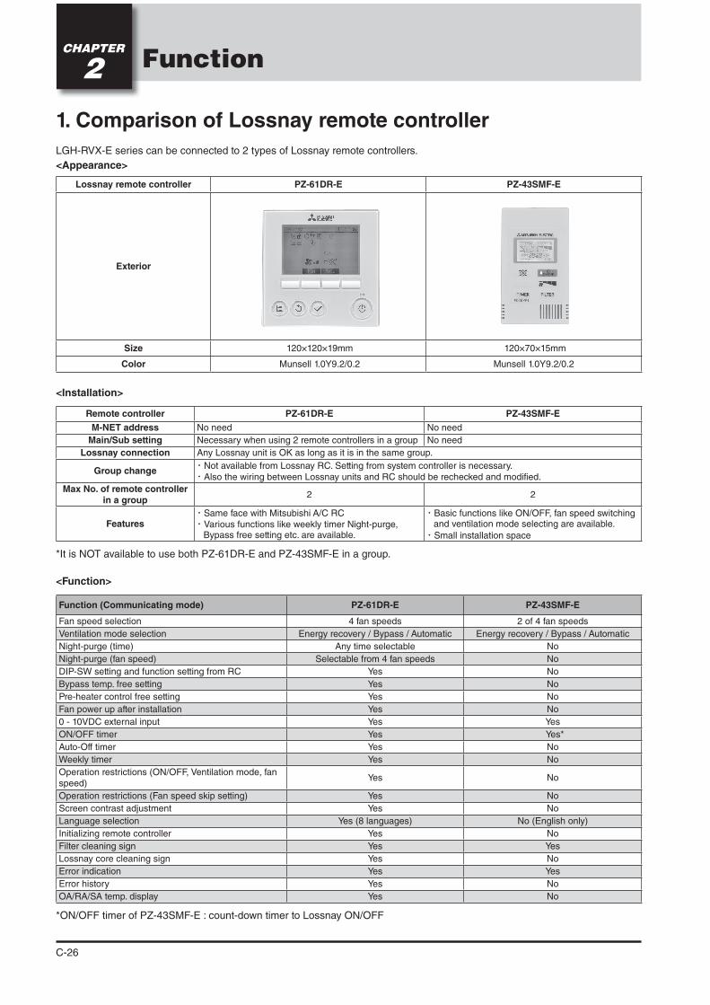
1. Comparison of Lossnay remote controller
LGH-RVX-E series can be connected to 2 types of Lossnay remote controllers.
<Appearance>
FunctionCHAPTER
2
Remote controller PZ-61DR-E PZ-43SMF-E
M-NET address No need No need
Main/Sub setting Necessary when using 2 remote controllers in a group No need
Lossnay connection
Group change・Not available from Lossnay RC. Setting from system controller is necessary.・Also the wiring between Lossnay units and RC should be rechecked and modified.
Max No. of remote controller in a group
2 2
Features・Same face with Mitsubishi A/C RC・Various functions like weekly timer Night-purge,
Bypass free setting etc. are available.
・Basic functions like ON/OFF, fan speed switching and ventilation mode selecting are available.
・Small installation space
*It is NOT available to use both PZ-61DR-E and PZ-43SMF-E in a group.
<Installation>
<Function>
Lossnay remote controller PZ-61DR-E PZ-43SMF-E
Exterior
Size 120×120×19mm 120×70×15mm
Color
Function (Communicating mode) PZ-61DR-E PZ-43SMF-E
Fan speed selection 4 fan speeds 2 of 4 fan speeds
Ventilation mode selection Energy recovery / Bypass / Automatic Energy recovery / Bypass / Automatic
Night-purge (time) Any time selectable No
Night-purge (fan speed) Selectable from 4 fan speeds No
DIP-SW setting and function setting from RC No
Bypass temp. free setting No
Pre-heater control free setting No
Fan power up after installation No
0 - 10VDC external input
ON/OFF timer
Auto-Off timer No
Weekly timer No
Operation restrictions (ON/OFF, Ventilation mode, fan speed)
No
Operation restrictions (Fan speed skip setting) No
Screen contrast adjustment No
Language selection No (English only)
Initializing remote controller No
Filter cleaning sign
Lossnay core cleaning sign No
Error indication
Error history No
OA/RA/SA temp. display No
*ON/OFF timer of PZ-43SMF-E : count-down timer to Lossnay ON/OFF
C-27
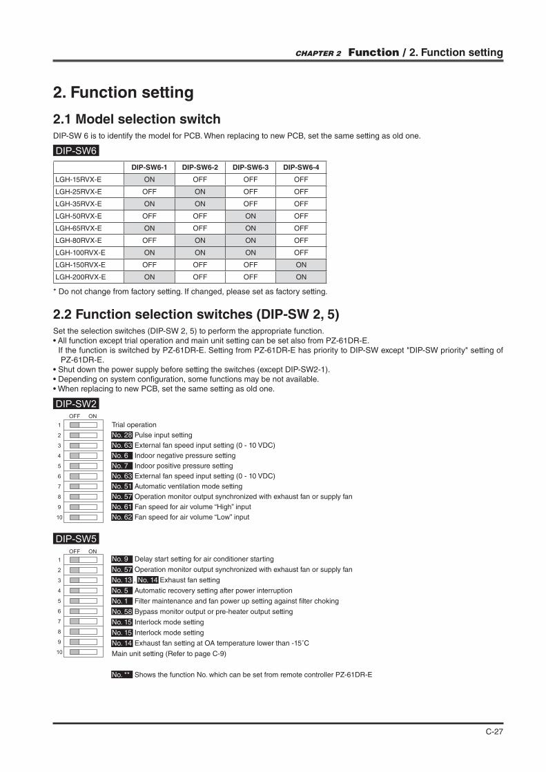
DIP-SW6-1 DIP-SW6-2 DIP-SW6-3 DIP-SW6-4
LGH-15RVX-E ON OFF OFF OFF
LGH-25RVX-E OFF ON OFF OFF
LGH-35RVX-E ON ON OFF OFF
LGH-50RVX-E OFF OFF ON OFF
LGH-65RVX-E ON OFF ON OFF
LGH-80RVX-E OFF ON ON OFF
LGH-100RVX-E ON ON ON OFF
LGH-150RVX-E OFF OFF OFF ON
LGH-200RVX-E ON OFF OFF ON
2.2 Function selection switches (DIP-SW 2, 5)Set the selection switches (DIP-SW 2, 5) to perform the appropriate function.
PZ-61DR-E.
2. Function setting
2.1 Model selection switchDIP-SW 6 is to identify the model for PCB. When replacing to new PCB, set the same setting as old one.
* Do not change from factory setting. If changed, please set as factory setting.
DIP-SW2
DIP-SW5
DIP-SW6
1
2
3
4
5
6
7
8
9
10
OFF ON
1
2
3
4
5
6
7
8
9
10
OFF ON
Trial operation
No. 28 Pulse input setting
No. 63 External fan speed input setting (0 - 10 VDC)
No. 6 Indoor negative pressure setting
No. 7 Indoor positive pressure setting
No. 63 External fan speed input setting (0 - 10 VDC)
No. 51 Automatic ventilation mode setting
No. 57 Operation monitor output synchronized with exhaust fan or supply fan
No. 61 Fan speed for air volume “High” input
No. 62 Fan speed for air volume “Low” input
No. 9 Delay start setting for air conditioner starting
No. 57 Operation monitor output synchronized with exhaust fan or supply fan
No. 13 , No. 14 Exhaust fan setting
No. 5 Automatic recovery setting after power interruption
No. 1 Filter maintenance and fan power up setting against "lter choking
No. 58 Bypass monitor output or pre-heater output setting
No. 15 Interlock mode setting
No. 15 Interlock mode setting
No. 14 Exhaust fan setting at OA temperature lower than -15˚C
Main unit setting (Refer to page C-9)
No. ** Shows the function No. which can be set from remote controller PZ-61DR-E
CHAPTER 2 Function / 2. Function setting
C-28
2.3 Function setting from PZ-61DR-E
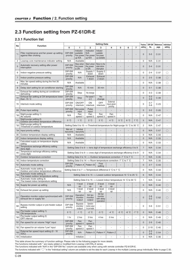
2.3.1 Function list
No FunctionSetting Data Factory
settingDIP-SW
No.Reference
pageIndividual
setting0 1 2 3 4 5 6 7
*1Filter maintenance and fan power up setting against "lter choking
DIP-SW priority
Indicator available Fan power up N/A
Indicator N/A Fan power up N/A
Indicator available Fan power up available
- - - - 0 5-5 C-31 -
2 Lossnay core maintenance indicator setting N/A Available - - - - - - 0 N/A C-31 -
5 Automatic recovery setting after power interruption
DIP-SW priority
Stop when the power is ON
Start when the power is ON
Return to the state before interruption
- - - - 0 5-4 C-31 -
6 Indoor negative pressure settingDIP-SW priority
N/ASupply 1
downSupply 2
down- - - - 0 2-4 C-37
7 Indoor positive pressure settingDIP-SW priority
N/AExhaust 1 down
Exhaust 2 down
- - - - 0 2-5 C-38
8 Max. fan speed setting during the "rst 30 minutes
N/A Available - - - - - - 0 N/A C-38
9 Delay start setting for air conditioner startingDIP-SW priority
N/A 15 min 30 min - - - - 0 5-1 C-38 -
13 Exhaust fan setting during air conditioner defrosting
DIP-SW priority
Stop No change - - - - - 0 5-3 C-39 -
14 Exhaust fan setting at OA temperature lower than -15 ˚C
DIP-SW priority
StopFan speed 1
or 2No
change- - - - 0
5-35-9
C-39 -
15 Interlock mode settingDIP-SW priority
ON/OFF interlock
ON interlock
OFF interlock
External input given
priority- - - 0
5-75-8
C-23 -
28 Pulse input settingDIP-SW priority
Non-pulse input
Pulse input
- - - - - 0 2-2 C-20 -
*30 Night-purge setting 1) Air volume
N/AFan
speed 1Fan
speed 2Fan
speed 3Fan
speed 4- - - 0 N/A C-47 -
*31 Night-purge setting 2)Outdoor and indoor temperature difference
0 ˚C 1 ˚C 2 ˚C 3 ˚C 4 ˚C 5 ˚C 6 ˚C 7 ˚C 5 N/A C-47 -
*32 Night-purge setting 3) Threshold of outdoor temperature
Setting Data 0 to 15 --> Threshold temperature for Night-purge 15 ˚C to 30 ˚C 2 N/A C-47 -
*34 Input priority settingMain unit
input priorityIndividual
input priority- - - - - - 0 N/A C-57
36 Outdoor temperature display setting N/A Available - - - - - - 0 N/A C-33 -
37 Indoor temperature display setting N/A Available - - - - - - 0 N/A C-33 -
38 Calculated supply air temperature display setting
N/A Available - - - - - - 0 N/A C-33 -
39 Temperature exchange efficiency setting (tens digit)
Setting Data 0 to 9 --> tens digit of temperature exchange efficiency 0 to 9 7 N/A C-34 -
40 Temperature exchange efficiency setting (ones digit)
Setting Data 0 to 9 --> ones digit of temperature exchange efficiency 0 to 9 0 N/A C-34 -
*41 Outdoor temperature correction Setting Data 0 to 14 --> Outdoor temperature correction -7 ˚C to 7 ˚C 7 N/A C-35 -
*42 Indoor temperature correction Setting Data 0 to 14 --> Room temperature correction -7 ˚C to 7 ˚C 7 N/A C-35 -
*51 Automatic mode settingDIP-SW priority
Pattern A Pattern BFree
setting- - - - 0 2-7 C-43 -
*52 Automatic mode setting 1)Outdoor and indoor temperature difference
Setting Data 0 to 7 --> Temperature difference 0 ˚C to 7 ˚C 0 N/A C-44 -
*53 Automatic mode setting 2)The lowest outdoor temperature setting
Setting Data 0 to 15 --> Lowest outdoor temperature 10 ˚C to 25 ˚C 6 N/A C-44 -
*54 Automatic mode setting 3)The lowest indoor temperature setting
Setting Data 0 to 15 --> Lowest indoor temperature 15 ˚C to 30 ˚C 1 N/A C-44 -
*55 Supply fan power up setting N/A1 level
up2 level
up3 level
up4 level
up- - - 0 N/A C-40
*56 Exhaust fan power up setting N/A1 level
up2 level
up3 level
up4 level
up- - - 0 N/A C-40
57 Operation monitor output synchronized with exhaust fan or supply fan
DIP-SW priority
Operation monitor output
SA fan monitor output
SA fan monitor
with delay operation
- - - - 02-8 5-2
C-52
58 Bypass monitor output or pre-heater output setting
DIP-SW priority
Bypass monitor output
Operation monitor output for pre-heater
- - - - - 0 5-6 C-51
*59 Pre-heater output setting 1)ON temperature
0 ˚C -1 ˚C -2 ˚C -3 ˚C -4 ˚C -5 ˚C -6 ˚C -7 ˚C 0 N/A C-48
*60 Pre-heater output setting 2)OFF interval
1 hr 2 hrs 3 hrs 4 hrs 5 hrs - - - 0 N/A C-49
*61 Fan speed for air volume “High” inputDIP-SW priority
Fan speed 4
Fan speed 3
- - - - - 0 2-9 C-40 -
*62 Fan speed for air volume “Low” inputDIP-SW priority
Fan speed 2
Fan speed 1
- - - - - 0 2-10 C-40 -
*63 External fan speed input setting (0 - 10 VDC)
DIP-SW priority
N/A Pattern X Pattern Z - - - 02-32-6
C-54
100 Initialization - Initialize - - - - - - 0 N/A C-36 -
This table shows the summary of function settings. Please refer to the following pages for more details.The functions indicated with * are newly added or modi"ed from Lossnay LGH-RX5-E series.The functions indicated with “N/A” in the “DIP-SW No.” column are available only when using with remote controller PZ-61DR-E.
The functions indicated with “ ” in the “Individual setting” column are avilable to set the data for each Lossnay in the multiple Lossnay group individually. Refer to page C-30.
CHAPTER 2 Function / 2. Function setting
C-29
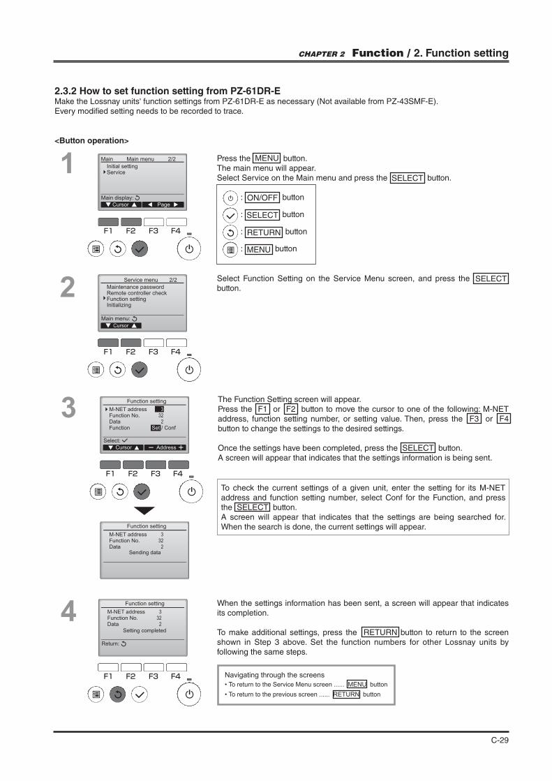
2.3.2 How to set function setting from PZ-61DR-EMake the Lossnay units' function settings from PZ-61DR-E as necessary (Not available from PZ-43SMF-E). Every modi"ed setting needs to be recorded to trace.
<Button operation>
F1 F2 F3 F4
2/2Main
Main display:
Cursor Page
Main menu
Initial settingService1 Press the MENU button.
The main menu will appear. Select Service on the Main menu and press the SELECT button.
2
F1 F2 F3 F4
Service menu
Maintenance passwordRemote controller checkFunction settingInitializing
Main menu:
Cursor
2/2
3
To check the current settings of a given unit, enter the setting for its M-NET address and function setting number, select Conf for the Function, and press the SELECT button. A screen will appear that indicates that the settings are being searched for. When the search is done, the current settings will appear.
The Function Setting screen will appear.Press the F1 or F2 button to move the cursor to one of the following: M-NET address, function setting number, or setting value. Then, press the F3 or F4 button to change the settings to the desired settings.
Once the settings have been completed, press the SELECT button.A screen will appear that indicates that the settings information is being sent.
F1 F2 F3 F4
Set / Conf
Sending data
Cursor
Select:
M-NET addressFunction No.DataFunction
3
32
2
3
32
2
M-NET addressFunction No.Data
Function setting
Function setting
Address
4 3
32
2
M-NET addressFunction No.Data
Return:
Function setting
Setting completed
F1 F2 F3 F4
When the settings information has been sent, a screen will appear that indicates its completion.
To make additional settings, press the RETURN button to return to the screen shown in Step 3 above. Set the function numbers for other Lossnay units by following the same steps.
Navigating through the screens
To return to the Service Menu screen ...... MENU button
To return to the previous screen ...... RETURN button
: ON/OFF button
: SELECT button
: RETURN button
: MENU button
Select Function Setting on the Service Menu screen, and press the SELECT button.
CHAPTER 2 Function / 2. Function setting
C-30
3. Function setting contents
3.1 Trial Operation
After the system has been installed and before the ceiling panel is installed, make sure that wires are properly connected, then test the system’s operation, referring to the operation manual for the remote controller.
3.1.1 Trial operation using the remote controllers (PZ-61DR-E)Follow the procedure shown in the operation manual for the remote controller the functions below.
(1) Start operation.
(2) Fan speed selection.
(3) Ventilation mode selection.
(4) Stop operation.
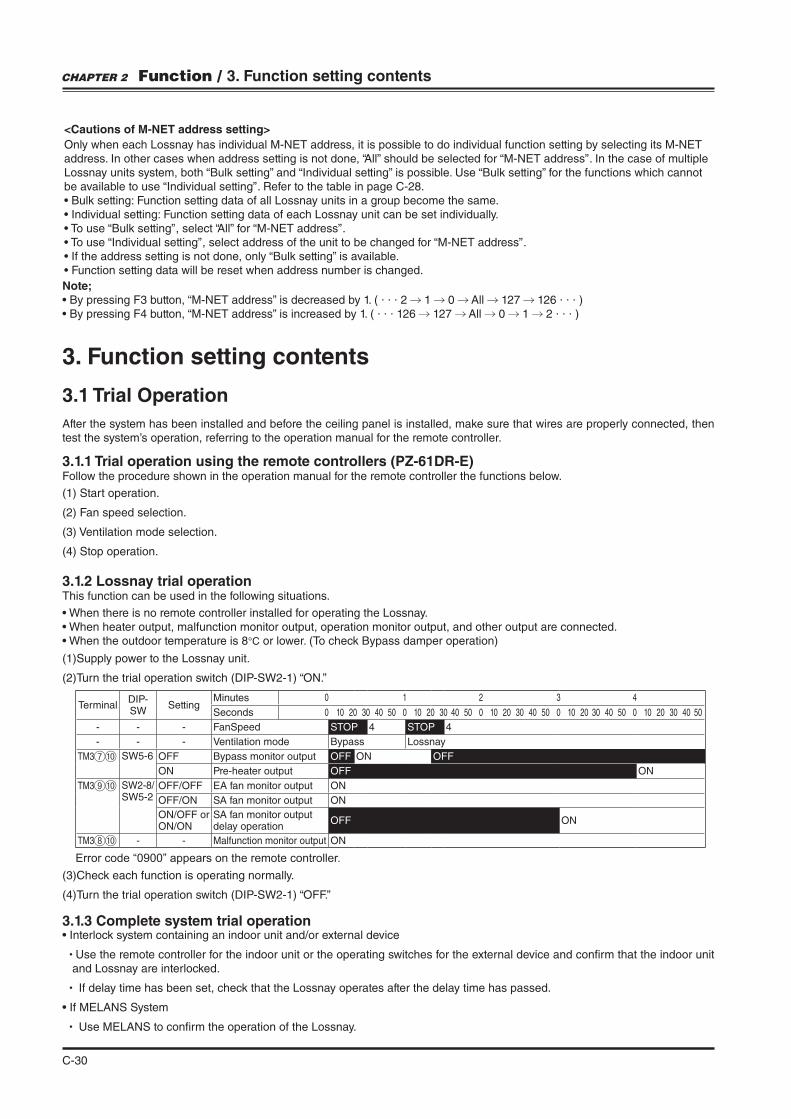
3.1.2 Lossnay trial operationThis function can be used in the following situations.
°C or lower. (To check Bypass damper operation)
(1) Supply power to the Lossnay unit.
(2) Turn the trial operation switch (DIP-SW2-1) “ON.”
3.1.3 Complete system trial operation
Use the remote controller for the indoor unit or the operating switches for the external device and con"rm that the indoor unit and Lossnay are interlocked.
If delay time has been set, check that the Lossnay operates after the delay time has passed.
Use MELANS to con"rm the operation of the Lossnay.
(3) Check each function is operating normally.
(4) Turn the trial operation switch (DIP-SW2-1) “OFF.”
TerminalDIP-SW
SettingMinutes 0 1 2 3 4
Seconds 0 10 20 30 40 50 0 10 20 30 40 50 0 10 20 30 40 50 0 10 20 30 40 50 0 10 20 30 40 50
- - - FanSpeed STOP 4 STOP 4
- - - Ventilation mode Bypass Lossnay
TM3 SW5-6 OFF Bypass monitor output OFF ON OFF
ON Pre-heater output OFF ON
TM3 SW2-8/SW5-2
OFF/OFF EA fan monitor output ON
OFF/ON SA fan monitor output ON
ON/OFF or ON/ON
SA fan monitor output delay operation
OFF ON
TM3 - - Malfunction monitor output ON
Error code “0900” appears on the remote controller.
CHAPTER 2 Function / 3. Function setting contents
<Cautions of M-NET address setting>
Only when each Lossnay has individual M-NET address, it is possible to do individual function setting by selecting its M-NET address. In other cases when address setting is not done, “All” should be selected for “M-NET address” . In the case of multiple Lossnay units system, both “Bulk setting” and “Individual setting” is possible. Use “Bulk setting” for the functions which cannot be available to use “Individual setting” . Refer to the table in page C-28.
Note;. . . 2 1 0 All 127 126 . . . )
. . . 126 127 All 0 1 2 . . . )
C-31
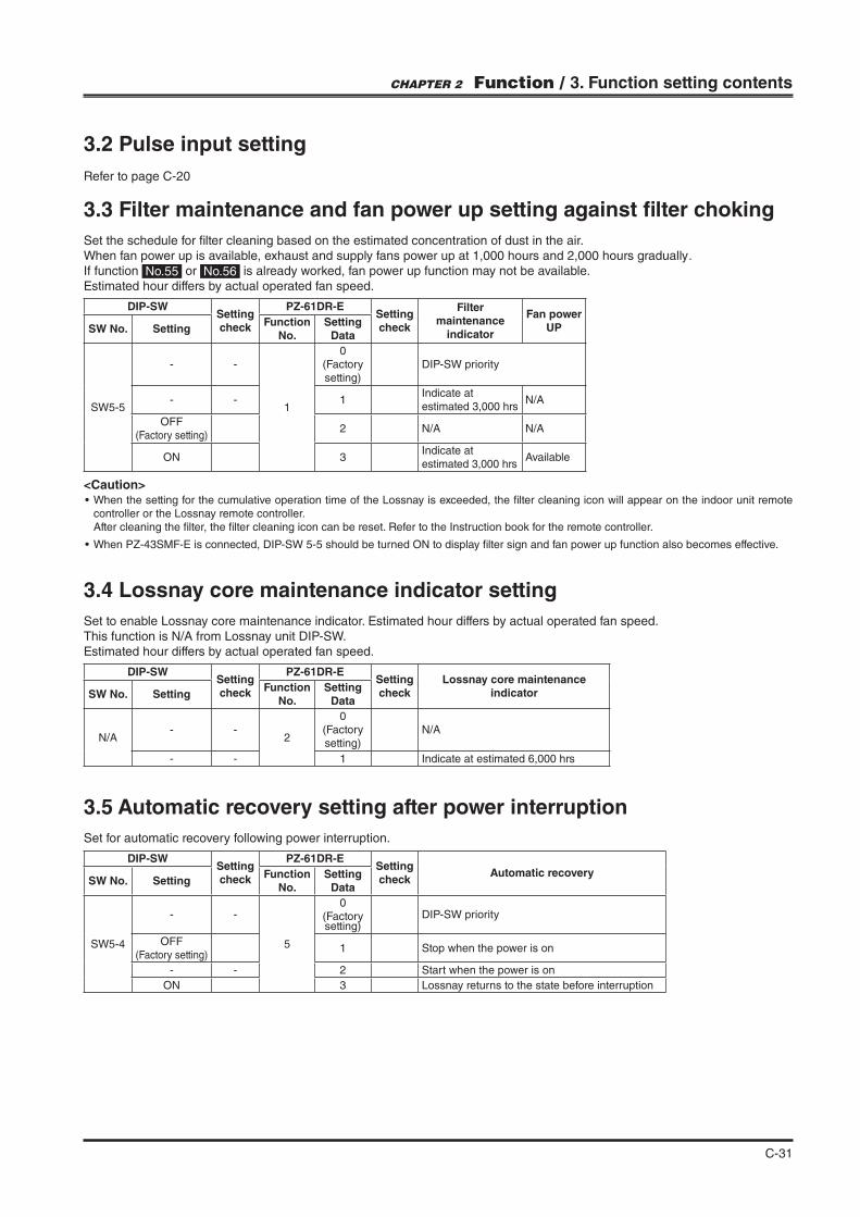
3.2 Pulse input setting
Refer to page C-20
<Caution>
controller or the Lossnay remote controller. After cleaning the "lter, the "lter cleaning icon can be reset. Refer to the Instruction book for the remote controller.
DIP-SWSetting check
PZ-61DR-ESetting check
Filter maintenance
indicator
Fan power UPSW No. Setting
Function No.
Setting Data
SW5-5
- -
1
0(Factory setting)
DIP-SW priority
- - 1Indicate at estimated 3,000 hrs
N/A
OFF (Factory setting)
2 N/A N/A
ON 3Indicate at estimated 3,000 hrs
Available
3.3 Filter maintenance and fan power up setting against !lter choking
Set the schedule for "lter cleaning based on the estimated concentration of dust in the air. When fan power up is available, exhaust and supply fans power up at 1,000 hours and 2,000 hours gradually .If function No.55 or No.56 is already worked, fan power up function may not be available.Estimated hour differs by actual operated fan speed.
3.4 Lossnay core maintenance indicator setting
Set to enable Lossnay core maintenance indicator. Estimated hour differs by actual operated fan speed.This function is N/A from Lossnay unit DIP-SW.Estimated hour differs by actual operated fan speed.
DIP-SWSetting check
PZ-61DR-ESetting check
Lossnay core maintenance indicatorSW No. Setting
Function No.
Setting Data
N/A- -
2
0(Factory setting)
N/A
- - 1 Indicate at estimated 6,000 hrs
DIP-SWSetting check
PZ-61DR-ESetting check
Automatic recoverySW No. Setting
Function No.
Setting Data
SW5-4
- -
5
0(Factory setting)
DIP-SW priority
OFF (Factory setting)
1 Stop when the power is on
- - 2 Start when the power is on
ON 3 Lossnay returns to the state before interruption
3.5 Automatic recovery setting after power interruption
Set for automatic recovery following power interruption.
CHAPTER 2 Function / 3. Function setting contents
C-32
3.6 Indoor negative pressure setting
Refer to “Fan speed control ”(C-37).
3.7 Indoor positive pressure setting
Refer to “Fan speed control ”(C-38).
3.8 Max. fan speed setting during the !rst 30 minutes
Refer to “Fan speed control ”(C-38).
3.9 Delay start setting for air conditioner starting
Refer to “Fan speed control ”(C-38).
3.10 Exhaust fan setting during air conditioner defrosting or at OA temperature lower than -15 ˚C
Refer to “Fan speed control ”(C-39).
3.11 Interlock mode setting
Refer to “Interlocked system with an external device”(C-23).
3.12 Pulse input setting
Refer to “4.5 Interlocked system with an external device”(C-20).
3.13 Night-purge setting 1) Air volume
Refer to “Night-purge function ”(C-47).
3.14 Night-purge setting 2) Outdoor and indoor temperature difference
Refer to “Night-purge function ”(C-47).
3.15 Night-purge setting 3) Threshold of outdoor temperature
Refer to “Night-purge function ”(C-47).
3.16 Input priority setting
Refer to “Input terminal ”(C-57).
CHAPTER 2 Function / 3. Function setting contents
C-33
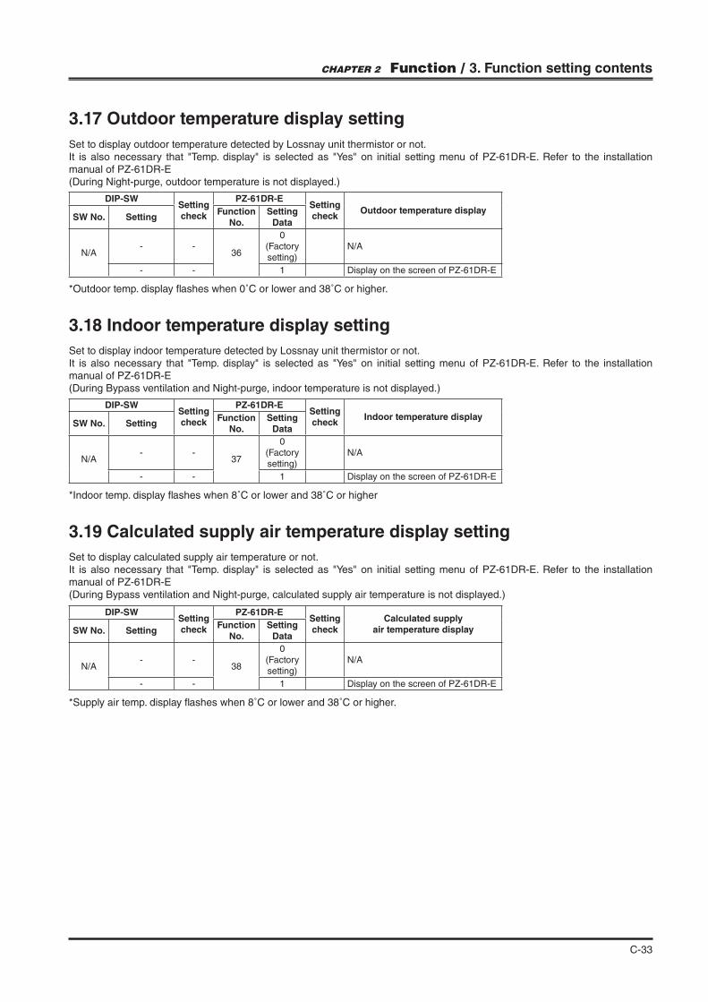
3.17 Outdoor temperature display setting
Set to display outdoor temperature detected by Lossnay unit thermistor or not.
manual of PZ-61DR-E(During Night-purge, outdoor temperature is not displayed.)
*Outdoor temp. display #ashes when 0˚C or lower and 38˚C or higher.
DIP-SWSetting check
PZ-61DR-ESetting check
Outdoor temperature displaySW No. Setting
Function No.
Setting Data
N/A- -
36
0(Factory setting)
N/A
- - 1 Display on the screen of PZ-61DR-E
3.18 Indoor temperature display setting
Set to display indoor temperature detected by Lossnay unit thermistor or not.
manual of PZ-61DR-E(During Bypass ventilation and Night-purge, indoor temperature is not displayed.)
3.19 Calculated supply air temperature display setting
Set to display calculated supply air temperature or not.
manual of PZ-61DR-E(During Bypass ventilation and Night-purge, calculated supply air temperature is not displayed.)
DIP-SWSetting check
PZ-61DR-ESetting check
Indoor temperature displaySW No. Setting
Function No.
Setting Data
N/A- -
37
0(Factory setting)
N/A
- - 1 Display on the screen of PZ-61DR-E
DIP-SWSetting check
PZ-61DR-ESetting check
Calculated supplyair temperature displaySW No. Setting
Function No.
Setting Data
N/A- -
38
0(Factory setting)
N/A
- - 1 Display on the screen of PZ-61DR-E
*Indoor temp. display #ashes when 8˚C or lower and 38˚C or higher
*Supply air temp. display #ashes when 8˚C or lower and 38˚C or higher.
CHAPTER 2 Function / 3. Function setting contents
C-34
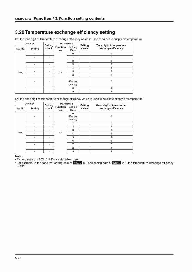
3.20 Temperature exchange efficiency setting
Set the tens digit of temperature exchange efficiency which is used to calculate supply air temperature.
DIP-SWSetting check
PZ-61DR-ESetting check
Tens digit of temperature exchange efficiencySW No. Setting
Function No.
Setting Data
N/A
- -
39
0 0
- - 1 1
- - 2 2
- - 3 3
- - 4 4
- - 5 5
- - 6 6
- -7
(Factory setting)
7
- - 8 8
- - 9 9
DIP-SWSetting check
PZ-61DR-ESetting check
Ones digit of temperature exchange efficiencySW No. Setting
Function No.
Setting Data
N/A
- -
40
0(Factory setting)
0
- - 1 1
- - 2 2
- - 3 3
- - 4 4
- - 5 5
- - 6 6
- - 7 7
- - 8 8
- - 9 9
Set the ones digit of temperature exchange efficiency which is used to calculate supply air temperature.
CHAPTER 2 Function / 3. Function setting contents
Note;
No.39 is 8 and setting data of No.40 is 5, the temperature exchange efficiency
C-35
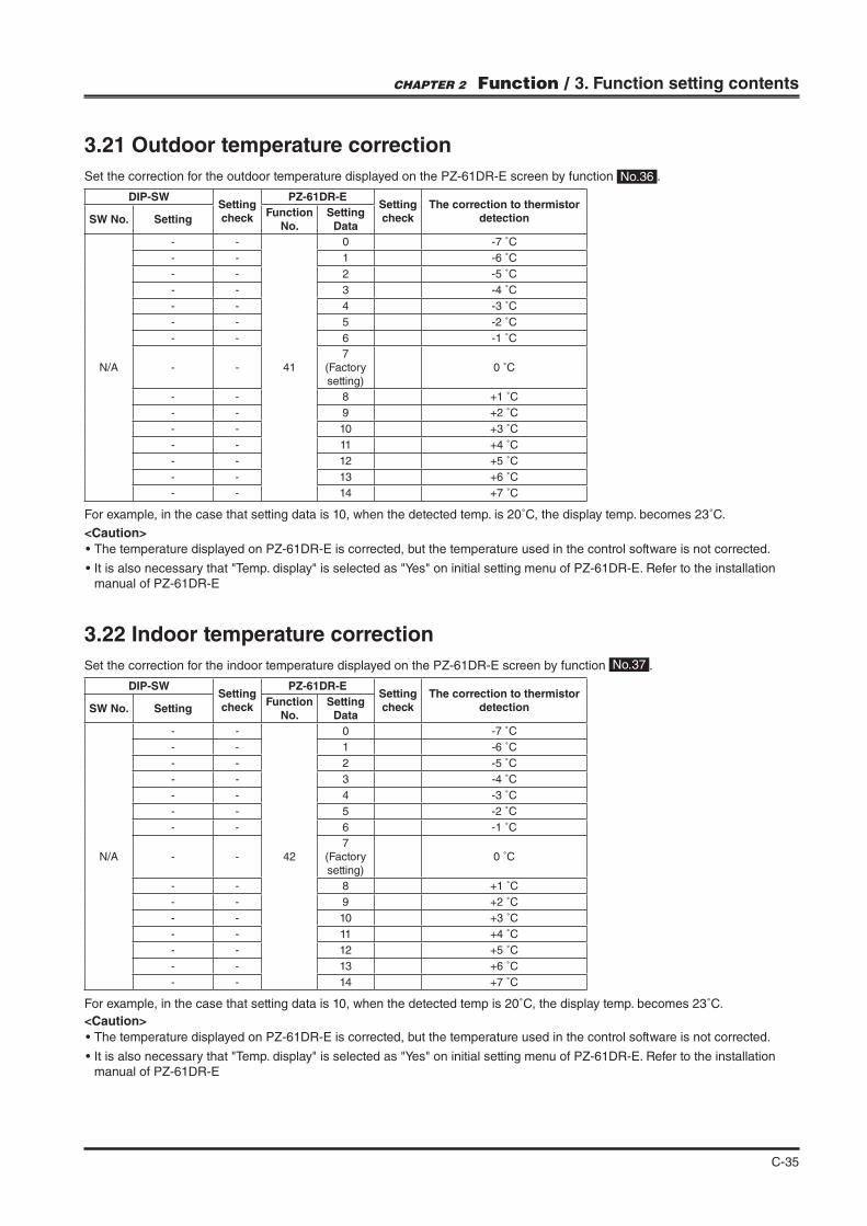
For example, in the case that setting data is 10, when the detected temp. is 20˚C, the display temp. becomes 23˚C.
3.21 Outdoor temperature correction
Set the correction for the outdoor temperature displayed on the PZ-61DR-E screen by function No.36 .
DIP-SWSetting check
PZ-61DR-ESetting check
The correction to thermistor detectionSW No. Setting
Function No.
Setting Data
N/A
- -
41
0 -7 ˚C
- - 1 -6 ˚C
- - 2 -5 ˚C
- - 3 -4 ˚C
- - 4 -3 ˚C
- - 5 -2 ˚C
- - 6 -1 ˚C
- -7
(Factory setting)
0 ˚C
- - 8 +1 ˚C
- - 9 +2 ˚C
- - 10 +3 ˚C
- - 11 +4 ˚C
- - 12 +5 ˚C
- - 13 +6 ˚C
- - 14 +7 ˚C
3.22 Indoor temperature correction
Set the correction for the indoor temperature displayed on the PZ-61DR-E screen by function No.37 .
DIP-SWSetting check
PZ-61DR-ESetting check
The correction to thermistor detectionSW No. Setting
Function No.
Setting Data
N/A
- -
42
0 -7 ˚C
- - 1 -6 ˚C
- - 2 -5 ˚C
- - 3 -4 ˚C
- - 4 -3 ˚C
- - 5 -2 ˚C
- - 6 -1 ˚C
- -7
(Factory setting)
0 ˚C
- - 8 +1 ˚C
- - 9 +2 ˚C
- - 10 +3 ˚C
- - 11 +4 ˚C
- - 12 +5 ˚C
- - 13 +6 ˚C
- - 14 +7 ˚C
For example, in the case that setting data is 10, when the detected temp is 20˚C, the display temp. becomes 23˚C.
CHAPTER 2 Function / 3. Function setting contents
<Caution>
manual of PZ-61DR-E
<Caution>
manual of PZ-61DR-E
C-36
3.23 Automatic ventilation mode settingRefer to “Ventilation mode control” (C-43)
3.24 Automatic mode setting 1) Outdoor and indoor temperature difference
Refer to “Ventilation mode control” (C-44)
3.25 Automatic mode setting 2) The lowest outdoor temperature
Refer to “Ventilation mode control” (C-44)
3.26 Automatic mode setting 3) The lowest indoor temperature setting
Refer to “Ventilation mode control” (C-44)
3.27 Supply fan power up setting and Exhaust fan power up settingRefer to “Fan speed control” (C-40)
3.28 Operation monitor output synchronized with exhaust fan or supply fan
Refer to “External input / output terminal” (C-52)
3.29 Bypass monitor output or Pre-heater output settingRefer to “External input / output terminal“ (C-51)
3.30 Pre-heater output setting 1) ON temperatureRefer to “Cautions of Lossnay operation in cold region“ (C-48)
3.31 Pre-heater output setting 2) OFF intervalRefer to “Cautions of Lossnay operation in cold region“ (C-49)
3.32 Fan speed for air volume “High” inputRefer to “Fan speed control” (C-40).
3.33 Fan speed for air volume “Low” inputRefer to “Fan speed control” (C-40).
3.34 External fan speed input setting (0 - 10 VDC)Refer to “External input / output terminal” (C-54).
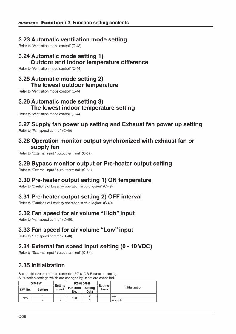
3.35 Initialization
Set to initialize the remote controller PZ-61DR-E function setting.All function settings which are changed by users are cancelled.
DIP-SWSetting check
PZ-61DR-ESetting check
InitializationSW No. Setting
Function No.
Setting Data
N/A- -
1000 N/A
- - 1 Available
CHAPTER 2 Function / 3. Function setting contents
C-37
4. Fan speed control
4.1 Fan speed control for each system
Following controls can be performed according to system con"guration.
SystemRemote controllersSystem controllers
Air volume
BasicSystem
Stand-alone/multipleLossnay and Lossnay remote controller: PZ-61DR-E
Lossnay remote controller PZ-61DR-E the remote controller.
Stand-alone/multipleLossnay and Lossnay remote controller: PZ-43SMF-E
Lossnay remote controller PZ-43SMF-E the remote controller.
System interlocked with Mr.Slim
MA remote controller PAR-31MAA(Remote controller connection prohibited with Lossnay)
Fan speed High / Low are selectable by ventilation operation of the remote controller.
Level signal/pulse signal output device and external device only
None Fixed to fan speed 4
M-NETControl
Stand-alone/multipleLossnay and Lossnay remote controller: PZ-61DR-E
Lossnay remote controllerPZ-61DR-E the remote controller
Stand-alone/multipleLossnay and Lossnay remote controller: PZ-43SMF-E
Lossnay remote controllerPZ-43SMF-E the remote controller.
M-NET Lossnay central control system
M-NET controller Selectable fan speed depends on the remote controller.
M-NET System interlocked with City Multi indoor units
Smart ME ControllerPAR-U02MEDAMA remote controller PAR-31MAA
Fan speed High / Low are selectable by ventilation operation of the remote controller.
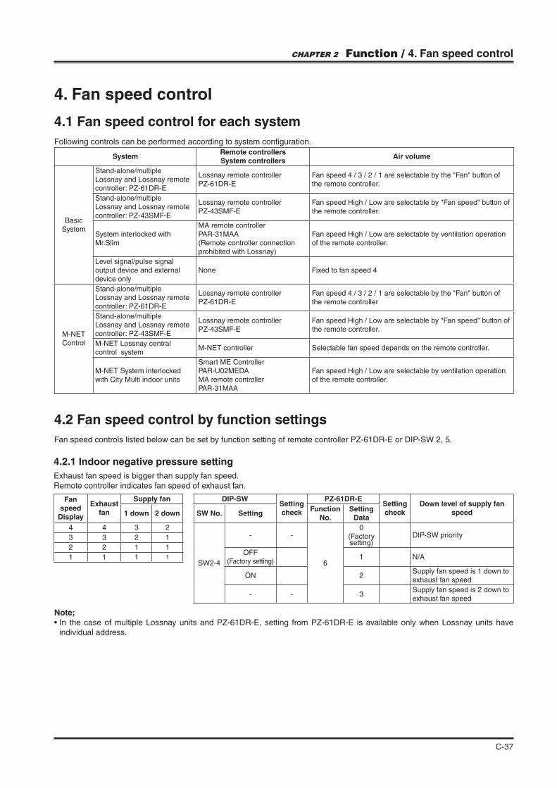
4.2 Fan speed control by function settings
Fan speed controls listed below can be set by function setting of remote controller PZ-61DR-E or DIP-SW 2, 5.
4.2.1 Indoor negative pressure setting
Exhaust fan speed is bigger than supply fan speed.Remote controller indicates fan speed of exhaust fan.
Fan speed
Display
Exhaust fan
Supply fan
1 down 2 down
4 4 3 2
3 3 2 1
2 2 1 1
1 1 1 1
DIP-SWSetting check
PZ-61DR-ESetting check
Down level of supply fan speedSW No. Setting
Function No.
Setting Data
SW2-4
- -
6
0(Factory setting)
DIP-SW priority
OFF (Factory setting)
1 N/A
ON 2Supply fan speed is 1 down to exhaust fan speed
- - 3Supply fan speed is 2 down to exhaust fan speed
CHAPTER 2 Function / 4. Fan speed control
Note;
individual address.

C-38
4.2.2 Indoor positive pressure setting
Supply fan speed is bigger than exhaust fan speed.Remote controller indicates fan speed of supply fan.
Fan speed
Display
Supply fan
Exhaust fan
1 down 2 down
4 4 3 2
3 3 2 1
2 2 1 1
1 1 1 1
DIP-SWSetting check
PZ-61DR-ESetting check
Down level of exhaust fan speedSW No. Setting
Function No.
Setting Data
SW2-5
- -
7
0(Factory setting)
DIP-SW priority
OFF (Factory setting)
1 N/A
ON 2Exhaust fan speed is 1 down to supply fan speed
- - 3Exhaust fan speed is 2 down to supply fan speed
4.2.3 Max. fan speed setting during the !rst 30 minutes
This sets the fan to run forcibly for 30 minutes when operation starts to ventilate the indoor area. After 30 minutes, fan speed can be changed. Use this setting if the indoor air is contaminated at night when the system is shut down and you desire to ventilate the indoor area quickly when operation is started in the morning.When this function is working, is displayed on PZ-61DR-E and selected fan speed is displayed.
DIP-SWSetting check
PZ-61DR-ESetting check
Max. fan speed settingduring the first 30 minutesSW No. Setting
Function No.
Setting Data
N/A- -
8
0(Factory setting)
N/A
- - 1 Available
4.2.4 Delay start setting for air conditioner starting
Delays Lossnay operation for 15 or 30 minutes when City Multi or Mr. Slim starts operating or when a external device starts operating. This function is not available during Night-purge or with pulse input setting.When this function is working, When not using Lossnay remote controller, it is possible to check the delay duration by seeing the LED1 on PCB.When the interval from the last Lossnay operation is 2hrs or less, Lossnay ignores this function.
DIP-SWSetting check
PZ-61DR-ESetting check
Lossnay delay startSW No. Setting
Function No.
Setting Data
SW5-1
- -
9
0(Factory setting)
DIP-SW priority
OFF (Factory setting)
1 N/A
- - 2 15 min
ON 3 30 min
CHAPTER 2 Function / 4. Fan speed control
Note;
individual address.
C-39
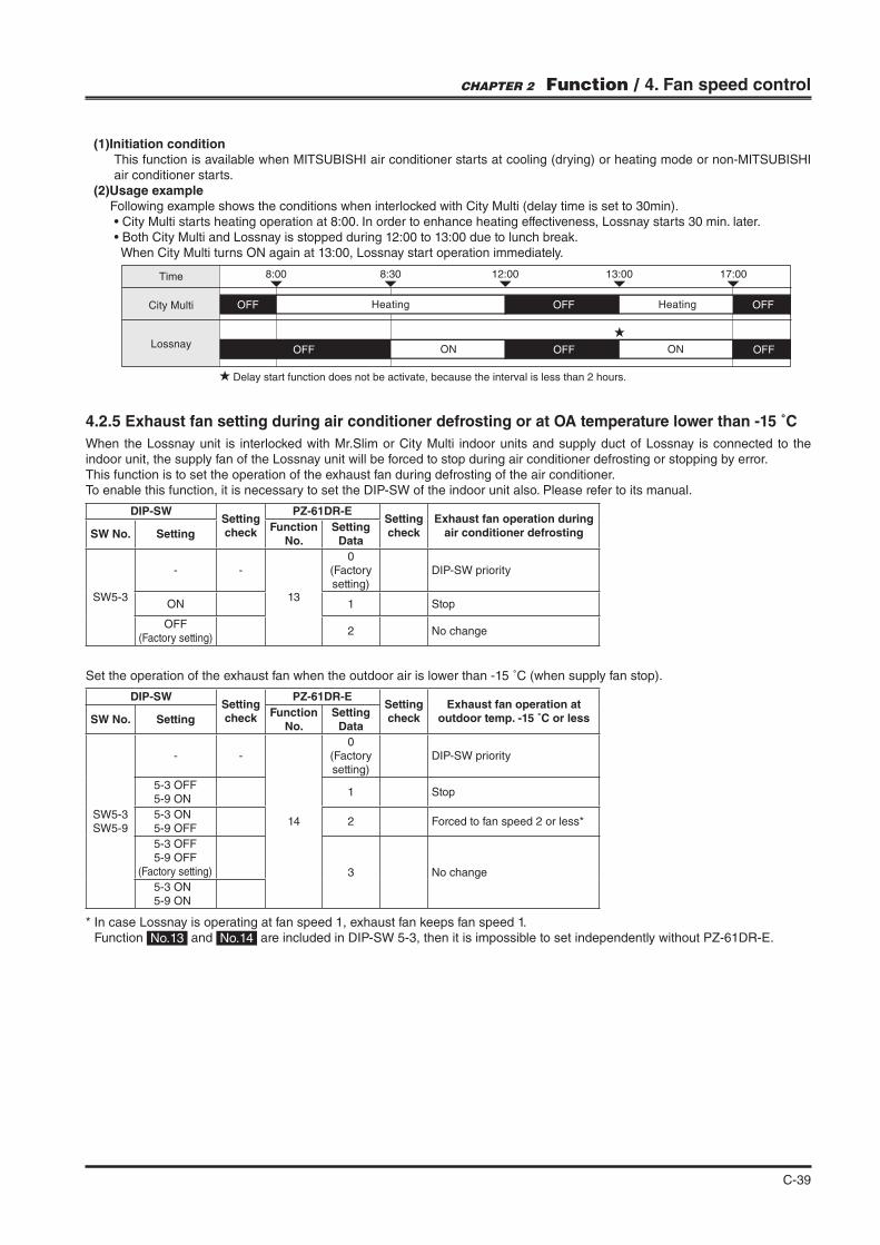
(1)Initiation condition This function is available when MITSUBISHI air conditioner starts at cooling (drying) or heating mode or non-MITSUBISHI air conditioner starts.
(2)Usage example Following example shows the conditions when interlocked with City Multi (delay time is set to 30min).
City Multi starts heating operation at 8:00. In order to enhance heating effectiveness, Lossnay starts 30 min. later.Both City Multi and Lossnay is stopped during 12:00 to 13:00 due to lunch break.
When City Multi turns ON again at 13:00, Lossnay start operation immediately.
Time
City Multi Heating Heating
LossnayOFF OFF OFFON ON
Delay start function does not be activate, because the interval is less than 2 hours.
OFF OFF OFF
8:00 8:30 12:00 13:00 17:00
4.2.5 Exhaust fan setting during air conditioner defrosting or at OA temperature lower than -15 ˚C
When the Lossnay unit is interlocked with Mr.Slim or City Multi indoor units and supply duct of Lossnay is connected to the indoor unit, the supply fan of the Lossnay unit will be forced to stop during air conditioner defrosting or stopping by error.This function is to set the operation of the exhaust fan during defrosting of the air conditioner.To enable this function, it is necessary to set the DIP-SW of the indoor unit also. Please refer to its manual.
Set the operation of the exhaust fan when the outdoor air is lower than -15 ˚C (when supply fan stop).
* In case Lossnay is operating at fan speed 1, exhaust fan keeps fan speed 1. Function No.13 and No.14 are included in DIP-SW 5-3, then it is impossible to set independently without PZ-61DR-E.
DIP-SWSetting check
PZ-61DR-ESetting check
Exhaust fan operation at outdoor temp. -15 ˚C or lessSW No. Setting
Function No.
Setting Data
SW5-3SW5-9
- -
14
0(Factory setting)
DIP-SW priority
5-3 OFF 5-9 ON
1 Stop
5-3 ON 5-9 OFF
2 Forced to fan speed 2 or less*
5-3 OFF 5-9 OFF(Factory setting) 3 No change
5-3 ON 5-9 ON
DIP-SWSetting check
PZ-61DR-ESetting check
Exhaust fan operation during air conditioner defrostingSW No. Setting
Function No.
Setting Data
SW5-3
- -
13
0(Factory setting)
DIP-SW priority
ON 1 Stop
OFF (Factory setting)
2 No change
CHAPTER 2 Function / 4. Fan speed control

C-40
4.2.6 Supply fan power up setting / Exhaust fan power up setting
Use these functions when the air volume needs to be increased after installation.Function No.55 is for supply fan power up and function No.56 is for exhaust fan power up.When function No.1 is ON and fan speed already reached the maximum power, this function is N/A.
DIP-SWSetting check
PZ-61DR-ESetting check
Supply fan power upSW No. Setting
Function No.
Setting Data
N/A
- -
55
0(Factory setting)
N/A
- - 1 1 level up
- - 2 2 level up
- - 3 3 level up
- - 4 4 level up
DIP-SWSetting check
PZ-61DR-ESetting check
Exhaust fan power upSW No. Setting
Function No.
Setting Data
N/A
- -
56
0(Factory setting)
N/A
- - 1 1 level up
- - 2 2 level up
- - 3 3 level up
- - 4 4 level up
4.2.7 Fan speed for air volume “High” input
Set the fan speed setting when receiving “High” signal from remote controllers (e.g. remote controller of City Multi and Mr. Slim, PZ-43SMF-E) that have High/Low or High/Middle/Low air volume.
DIP-SWSetting check
PZ-61DR-ESetting check
Operating fan speedSW No. Setting
Function No.
Setting Data
SW2-9
- -
61
0(Factory setting)
DIP-SW priority
OFF (Factory setting)
1 Fan speed 4
ON 2 Fan speed 3
4.2.8 Fan speed for air volume “Low” input
Set the fan speed setting when receiving “Low” signal from remote controllers (e.g. remote controller of City Multi and Mr. Slim, PZ-43SMF-E) that have High/Low.
4.2.9 External fan speed input setting (0-10VDC)
Refer to page C-54
DIP-SWSetting check
PZ-61DR-ESetting check
Operating fan speedSW No. Setting
Function No.
Setting Data
SW2-10
- -
62
0(Factory setting)
DIP-SW priority
OFF (Factory setting)
1 Fan speed 2
ON 2 Fan speed 1
CHAPTER 2 Function / 4. Fan speed control
<Caution>
<Caution>
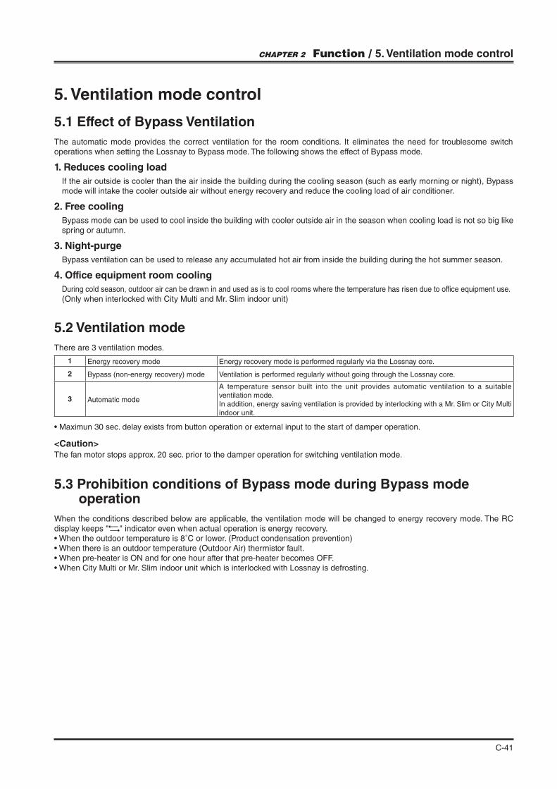
C-41
5. Ventilation mode control
5.1 Effect of Bypass Ventilation
The automatic mode provides the correct ventilation for the room conditions. It eliminates the need for troublesome switch operations when setting the Lossnay to Bypass mode. The following shows the effect of Bypass mode.
1. Reduces cooling load
If the air outside is cooler than the air inside the building during the cooling season (such as early morning or night), Bypass mode will intake the cooler outside air without energy recovery and reduce the cooling load of air conditioner.
2. Free cooling
Bypass mode can be used to cool inside the building with cooler outside air in the season when cooling load is not so big like spring or autumn.
3. Night-purge
Bypass ventilation can be used to release any accumulated hot air from inside the building during the hot summer season.
4. Office equipment room cooling
During cold season, outdoor air can be drawn in and used as is to cool rooms where the temperature has risen due to office equipment use.(Only when interlocked with City Multi and Mr. Slim indoor unit)
5.2 Ventilation mode
There are 3 ventilation modes.
1 Energy recovery mode Energy recovery mode is performed regularly via the Lossnay core.
2 Bypass (non-energy recovery) mode Ventilation is performed regularly without going through the Lossnay core.
3 Automatic mode
A temperature sensor built into the unit provides automatic ventilation to a suitable ventilation mode. In addition, energy saving ventilation is provided by interlocking with a Mr. Slim or City Multi indoor unit.
CHAPTER 2 Function / 5. Ventilation mode control
<Caution>The fan motor stops approx. 20 sec. prior to the damper operation for switching ventilation mode.
Maximun 30 sec. delay exists from button operation or external input to the start of damper operation.
5.3 Prohibition conditions of Bypass mode during Bypass mode operation
When the conditions described below are applicable, the ventilation mode will be changed to energy recovery mode. The RC
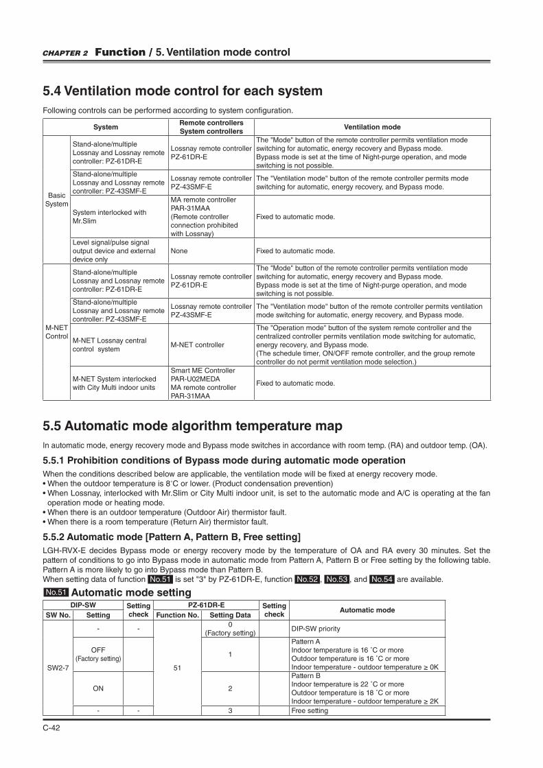
C-42
5.4 Ventilation mode control for each system
Following controls can be performed according to system con"guration.
SystemRemote controllersSystem controllers
Ventilation mode
BasicSystem
Stand-alone/multipleLossnay and Lossnay remote controller: PZ-61DR-E
Lossnay remote controller PZ-61DR-E
switching for automatic, energy recovery and Bypass mode.Bypass mode is set at the time of Night-purge operation, and mode switching is not possible.
Stand-alone/multipleLossnay and Lossnay remote controller: PZ-43SMF-E
Lossnay remote controller PZ-43SMF-E switching for automatic, energy recovery, and Bypass mode.
System interlocked with Mr.Slim
MA remote controller PAR-31MAA(Remote controller connection prohibited with Lossnay)
Fixed to automatic mode.
Level signal/pulse signal output device and external device only
None Fixed to automatic mode.
M-NETControl
Stand-alone/multipleLossnay and Lossnay remote controller: PZ-61DR-E
Lossnay remote controllerPZ-61DR-E
switching for automatic, energy recovery and Bypass mode.Bypass mode is set at the time of Night-purge operation, and mode switching is not possible.
Stand-alone/multipleLossnay and Lossnay remote controller: PZ-43SMF-E
Lossnay remote controllerPZ-43SMF-E mode switching for automatic, energy recovery, and Bypass mode.
M-NET Lossnay central control system
M-NET controllercentralized controller permits ventilation mode switching for automatic, energy recovery, and Bypass mode.(The schedule timer, ON/OFF remote controller, and the group remote controller do not permit ventilation mode selection.)
M-NET System interlocked with City Multi indoor units
Smart ME ControllerPAR-U02MEDAMA remote controllerPAR-31MAA
Fixed to automatic mode.
CHAPTER 2 Function / 5. Ventilation mode control
5.5 Automatic mode algorithm temperature map
In automatic mode, energy recovery mode and Bypass mode switches in accordance with room temp. (RA) and outdoor temp. (OA).
5.5.1 Prohibition conditions of Bypass mode during automatic mode operation
When the conditions described below are applicable, the ventilation mode will be "xed at energy recovery mode.˚C or lower. (Product condensation prevention)
operation mode or heating mode.
5.5.2 Automatic mode [Pattern A, Pattern B, Free setting]
LGH-RVX-E decides Bypass mode or energy recovery mode by the temperature of OA and RA every 30 minutes. Set the pattern of conditions to go into Bypass mode in automatic mode from Pattern A, Pattern B or Free setting by the following table. Pattern A is more likely to go into Bypass mode than Pattern B.When setting data of function No.51 No.52 , No.53 , and No.54 are available.
DIP-SW Setting check
PZ-61DR-E Setting check
Automatic modeSW No. Setting Function No. Setting Data
SW2-7
- -
51
0(Factory setting)
DIP-SW priority
OFF (Factory setting)
1
Pattern AIndoor temperature is 16 ˚C or moreOutdoor temperature is 16 ˚C or more
ON 2
Pattern BIndoor temperature is 22 ˚C or moreOutdoor temperature is 18 ˚C or more
- - 3 Free setting
No.51 Automatic mode setting
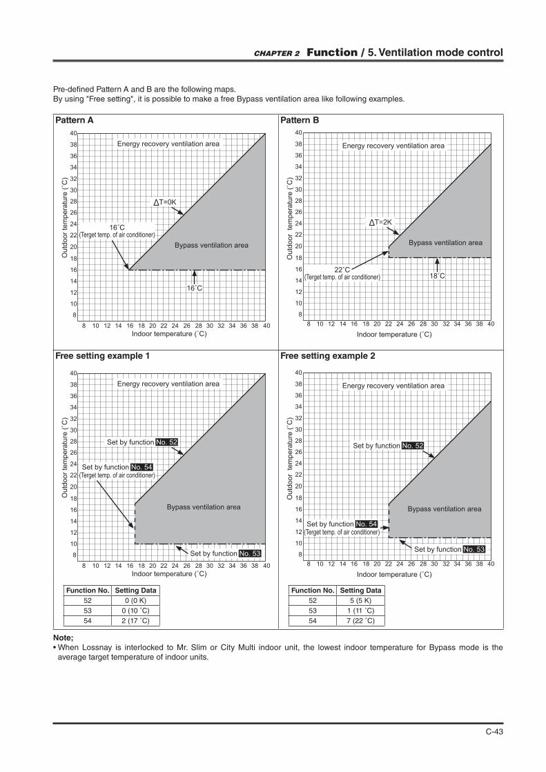
C-43
Pattern A Pattern B
8
8
10
12
14
16
18
20
22
24
26
28
30
32
34
36
38
40
1210 14 1816 20 22 24 26 28 30 32 34 36 38 40
Energy recovery ventilation area
Bypass ventilation area
T=0K
16˚C
8
8
10
12
14
16
18
20
22
24
26
28
30
32
34
36
38
40
1210 14 1816 20 22 24 26 28 30 32 34 36 38 40
Energy recovery ventilation area
Bypass ventilation area
T=2K
22˚C
Free setting example 1 Free setting example 2
8
8
10
12
14
16
18
20
22
24
26
28
30
32
34
36
38
40
1210 14 1816 20 22 24 26 28 30 32 34 36 38 40
Set by function No. 53
Energy recovery ventilation area
Bypass ventilation area
Set by function No. 52
Set by function No. 54 (Terget temp. of air
8
8
10
12
14
16
18
20
22
24
26
28
30
32
34
36
38
40
1210 14 1816 20 22 24 26 28 30 32 34 36 38 40
Energy recovery ventilation area
Bypass ventilation area
Set by function No. 53
Set by function No. 52
Set by function No. 54 (Terget temp. of air
Function No. Setting Data
52
53 0 (10 ˚C)
54 2 (17 ˚C)
Function No. Setting Data
52
53 1 (11 ˚C)
54 7 (22 ˚C)
Pre-de"ned Pattern A and B are the following maps.
CHAPTER 2 Function / 5. Ventilation mode control
16˚C
18˚C
Note;
average target temperature of indoor units.
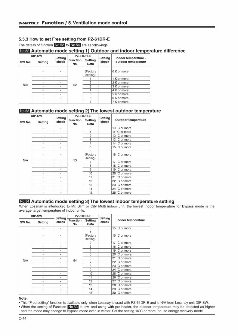
C-44
When Lossnay is interlocked to Mr. Slim or City Multi indoor unit, the lowest indoor temperature for Bypass mode is the average target temperature of indoor units.
DIP-SWSetting check
PZ-61DR-ESetting check
Indoor temperature - outdoor temperatureSW No. Setting
Function No.
Setting Data
N/A
- -
52
0(Factory setting)
- - 1
- - 2
- - 3
- - 4
- - 5
- - 6
- - 7
DIP-SWSetting check
PZ-61DR-ESetting check
Outdoor temperatureSW No. Setting
Function No.
Setting Data
N/A
- -
53
0 10 ˚C or more
- - 1 11 ˚C or more
- - 2 12 ˚C or more
- - 3 13 ˚C or more
- - 4 14 ˚C or more
- - 5 15 ˚C or more
- -6
(Factory setting)
16 ˚C or more
- - 7 17 ˚C or more
- - 8 18 ˚C or more
- - 9 19 ˚C or more
- - 10 20 ˚C or more
- - 11 21 ˚C or more
- - 12 22 ˚C or more
- - 13 23 ˚C or more
- - 14 24 ˚C or more
- - 15 25 ˚C or more
DIP-SWSetting check
PZ-61DR-ESetting check
Indoor temperatureSW No. Setting
Function No.
Setting Data
N/A
- -
54
0 15 ˚C or more
- -1
(Factory setting)
16 ˚C or more
- - 2 17 ˚C or more
- - 3 18 ˚C or more
- - 4 19 ˚C or more
- - 5 20 ˚C or more
- - 6 21 ˚C or more
- - 7 22 ˚C or more
- - 8 23 ˚C or more
- - 9 24 ˚C or more
- - 10 25 ˚C or more
- - 11 26 ˚C or more
- - 12 27 ˚C or more
- - 13 28 ˚C or more
- - 14 29 ˚C or more
- - 15 30 ˚C or more
Note;
No.53 is low, and using with pre-heater, the outdoor temperature may be detected as higher and the mode may change to Bypass mode even in winter. Set the setting 16˚C or more, or use energy recovery mode.
CHAPTER 2 Function / 5. Ventilation mode control
No.52 Automatic mode setting 1) Outdoor and indoor temperature difference
No.53 Automatic mode setting 2) The lowest outdoor temperature
No.54 Automatic mode setting 3) The lowest indoor temperature setting
5.5.3 How to set Free setting from PZ-61DR-E
The details of function No.52 to No.54 are as followings
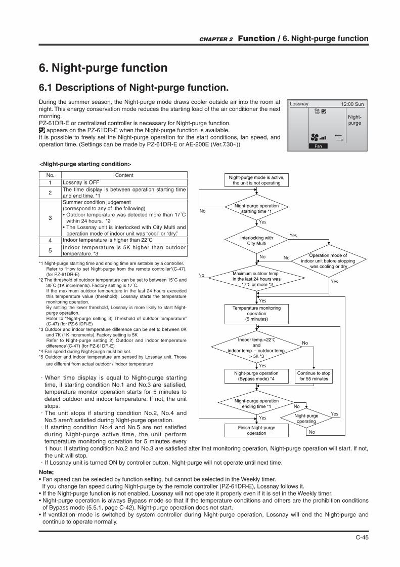
C-45
6. Night-purge function
6.1 Descriptions of Night-purge function.
During the summer season, the Night-purge mode draws cooler outside air into the room at night. This energy conservation mode reduces the starting load of the air conditioner the next morning.PZ-61DR-E or centralized controller is necessary for Night-purge function.
appears on the PZ-61DR-E when the Night-purge function is available.It is possible to freely set the Night-purge operation for the start conditions, fan speed, and operation time. (Settings can be made by PZ-61DR-E or AE-200E (Ver.7.30~))
<Night-purge starting condition>
No. Content
1 Lossnay is OFF
2The time display is between operation starting time and end time. *1
3
Summer condition judgement(correspond to any of the following)
within 24 hours. *2
operation mode of indoor unit was “cool” or “dry”.
4 Indoor temperature is higher than 22˚C
5temperature. *3
*1 Night-purge starting time and ending time are settable by a controller.Refer to “How to set Night-purge from the remote controller”(C-47).(for PZ-61DR-E)
*2 The threshold of outdoor temperature can be set to between 15˚C and
If the maximum outdoor temperature in the last 24 hours exceeded this temperature value (threshold), Lossnay starts the temperature monitoring operation.By setting the lower threshold, Lossnay is more likely to start Night-purge operation.Refer to “Night-purge setting 3) Threshold of outdoor temperature” (C-47) (for PZ-61DR-E)
Refer to Night-purge setting 2) Outdoor and indoor temperature difference”(C-47) (for PZ-61DR-E)
*4 Fan speed during Night-purge must be set.*5 Outdoor and indoor temperature are sensed by Lossnay unit. Those
are different from actual outdoor / indoor temperature
・When time display is equal to Night-purge starting time, if starting condition No.1 and No.3 are satis"ed, temperature monitor operation starts for 5 minutes to detect outdoor and indoor temperature. If not, the unit stops.
・The unit stops if starting condition No.2, No.4 and No.5 aren't satis"ed during Night-purge operation.
・If starting condition No.4 and No.5 are not satis"ed during Night-purge active time, the unit perform temperature monitoring operation for 5 minutes every 1 hour. If starting condition No.2 and No.3 are satis"ed after that monitoring operation, Night-purge operation will start. If not, the unit will stop.
・If Lossnay unit is turned ON by controller button, Night-purge will not operate until next time.
Night-purge mode is active,
the unit is not operating
Night-purge operation
starting time *1
Interlocking with
City Multi
Maximum outdoor temp.
in the last 24 hours was
17˚C or more *2
Temperature monitoring
operation
(5 minutes)
Indoor temp.>22˚C
and
indoor temp. – outdoor temp.
> 5K *3
Night-purge operation
(Bypass mode) *4
Night-purge operation
ending time *1
Finish Night-purge
operation
Night-purge
operating
Continue to stop
for 55 minutes
Operation mode of
indoor unit before stopping
was cooling or dry
No
No
NoNo
No
No
No
Yes
Yes
Yes
Yes
YesYes
Yes
Note;
If you change fan speed during Night-purge by the remote controller (PZ-61DR-E), Lossnay follows it.
of Bypass mode (5.5.1, page C-42), Night-purge operation does not start.
continue to operate normally.
CHAPTER 2 Function / 6. Night-purge function
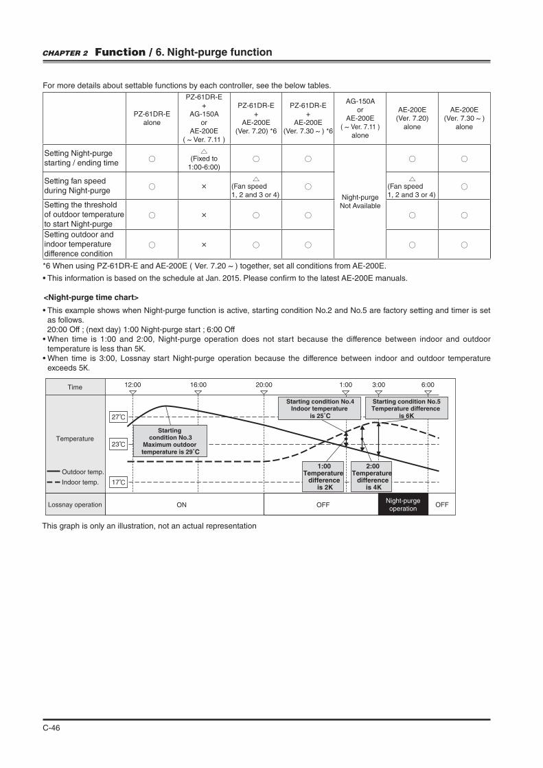
C-46
<Night-purge time chart>
as follows. 20:00 Off ; (next day) 1:00 Night-purge start ; 6:00 Off
temperature is less than 5 .
exceeds 5
Time 12:00
27℃
23℃
17℃
16:00 20:00 1:00 3:00 6:00
Temperature
Starting condition No.4Indoor temperature
is 25˚C
1:00Temperature
difference is 2K
2:00Temperature
difference is 4K
Starting condition No.5Temperature difference
is 6K
Lossnay operation ON OFF OFFNight-purge
operation
Outdoor temp.
Indoor temp.
Starting condition No.3
Maximum outdoor temperature is 29˚C
This graph is only an illustration, not an actual representation
For more details about settable functions by each controller, see the below tables.
PZ-61DR-E
alone
PZ-61DR-E
+
AG-150A
or
AE-200E
( ~ Ver. 7.11 )
PZ-61DR-E
+
AE-200E
(Ver. 7.20) *6
PZ-61DR-E
+
AE-200E
(Ver. 7.30 ~ ) *6
AG-150A
or
AE-200E
( ~ Ver. 7.11 )
alone
AE-200E
(Ver. 7.20)
alone
AE-200E
(Ver. 7.30 ~ )
alone
Setting Night-purge starting / ending time
(Fixed to 1:00-6:00)
Night-purgeNot Available
Setting fan speed during Night-purge
× (Fan speed1, 2 and 3 or 4)
(Fan speed1, 2 and 3 or 4)
Setting the threshold of outdoor temperature to start Night-purge
×
Setting outdoor and indoor temperature difference condition
×
*6 When using PZ-61DR-E and AE-200E ( Ver. 7.20 ~ ) together, set all conditions from AE-200E.
CHAPTER 2 Function / 6. Night-purge function
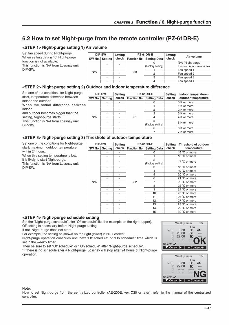
C-47
6.2 How to set Night-purge from the remote controller (PZ-61DR-E)
<STEP 1> Night-purge setting 1) Air volume
Set fan speed during Night-purge.When setting data is “0”, Night-purge function is not available.This function is N/A from Lossnay unit DIP-SW.
<STEP 2> Night-purge setting 2) Outdoor and indoor temperature difference
Set one of the conditions for Night-purge start, temperature difference between indoor and outdoor.When the actual difference between indoor and outdoor becomes bigger than the setting, Night-purge starts.This function is N/A from Lossnay unit DIP-SW.
<STEP 3> Night-purge setting 3) Threshold of outdoor temperature
Set one of the conditions for Night-purge start, maximum outdoor temperature within 24 hours.When this setting temperature is low,it is likely to start Night-purge.This function is N/A from Lossnay unit DIP-SW.
DIP-SW Setting check
PZ-61DR-E Setting check
Threshold of outdoor temperatureSW No. Setting Function No. Setting Data
N/A
- -
32
0 15 ˚C or more
- - 1 16 ˚C or more
- -2
(Factory setting)17 ˚C or more
- - 3 18 ˚C or more
- - 4 19 ˚C or more
- - 5 20 ˚C or more
- - 6 21 ˚C or more
- - 7 22 ˚C or more
- - 8 23 ˚C or more
- - 9 24 ˚C or more
- - 10 25 ˚C or more
- - 11 26 ˚C or more
- - 12 27 ˚C or more
- - 13 28 ˚C or more
- - 14 29 ˚C or more
- - 15 30 ˚C or more
DIP-SW Setting check
PZ-61DR-E Setting check
Air volumeSW No. Setting Function No. Setting Data
N/A
- -
30
0(Factory setting)
N/A (Night-purge function is not available)
- - 1 Fan speed 1
- - 2 Fan speed 2
- - 3 Fan speed 3
- - 4 Fan speed 4
DIP-SW Setting check
PZ-61DR-E Setting check
Indoor temperature - outdoor temperatureSW No. Setting Function No. Setting Data
N/A
- -
31
0
- - 1
- - 2
- - 3
- - 4
- -5
(Factory setting)
- - 6
- - 7
<STEP 4> Night-purge schedule settingSet the “Night-purge schedule” after “Off schedule” like the example on the right (upper).Off setting is necessary before Night-purge setting.If not, Night-purge does not start.
For example, the setting as shown on the right (lower) is NOT correct.
set in the weekly timer.
*If there is no schedule after a Night-purge, Lossnay will stop after 24 hours of Night-purge operation.
Note;How to set Night-purge from the centralized controller (AE-200E, ver. 7.30 or later), refer to the manual of the centralized controller.
OK
NG
CHAPTER 2 Function / 6. Night-purge function

C-48
7. Cautions of Lossnay Operation in cold region
7.1 Intermittent operation in cold region
In the event of the following, continuous fan operation for drawing in supply air is cancelled and intermittent operation starts.-10˚C to -15˚C : Intermittent operation 60 min ON, 10 min OFF.-15˚C or less : Intermittent operation 55 min OFF, 5 min ON. This is sensing operation for OA temp.
The icon is displayed on PZ-61DR-E when the supply fan is stopping.
7.2 Pre-heater control from Lossnay
Lossnay can output a signal to a pre-heater.
<Output setting>
No.58 or DIP-SW5-6. (refer to page C-51)
<Output condition>
OFF signal input.
<Error>
1) OA thermistor detects higher than 15˚C within 15 minutes after the output starts.2) OA thermistor detects -10˚C or lower, 60 minutes after the output starts.
DIP-SWSetting check
PZ-61DR-ESetting check
Outdoor temp. for Preheater output ONSW No. Setting
Function No.
Setting Data
N/A
- -
59
0(Factory setting)
0 ˚C or less
- - 1 -1 ˚C or less
- - 2 -2 ˚C or less
- - 3 -3 ˚C or less
- - 4 -4 ˚C or less
- - 5 -5 ˚C or less
- - 6 -6 ˚C or less
- - 7 -7 ˚C or less
CHAPTER 2 Function / 7. Cautions of Lossnay Operation in cold region
7.2.1 Pre-heater output setting 1) ON temperature
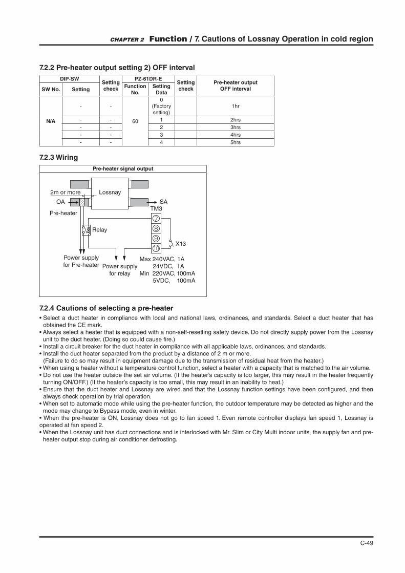
C-49
DIP-SWSetting check
PZ-61DR-ESetting check
Pre-heater output OFF intervalSW No. Setting
Function No.
Setting Data
N/A
- -
60
0(Factory setting)
1hr
- - 1 2hrs
- - 2 3hrs
- - 3 4hrs
- - 4 5hrs
obtained the CE mark.
unit to the duct heater. (Doing so could cause "re.)
(Failure to do so may result in equipment damage due to the transmission of residual heat from the heater.)
turning ON/OFF.) (If the heater’s capacity is too small, this may result in an inability to heat.)
always check operation by trial operation.
mode may change to Bypass mode, even in winter.
operated at fan speed 2.
heater output stop during air conditioner defrosting.
Pre-heater signal output
Lossnay
Pre-heater
Power supply
for Pre-heater Power supply
for relay
TM3
X13
Relay
OA SA
2m or more
9
8
7
10
Max 240VAC, 1A
24VDC, 1A
Min 220VAC, 100mA
5VDC, 100mA
CHAPTER 2 Function / 7. Cautions of Lossnay Operation in cold region
7.2.2 Pre-heater output setting 2) OFF interval
7.2.3 Wiring
7.2.4 Cautions of selecting a pre-heater
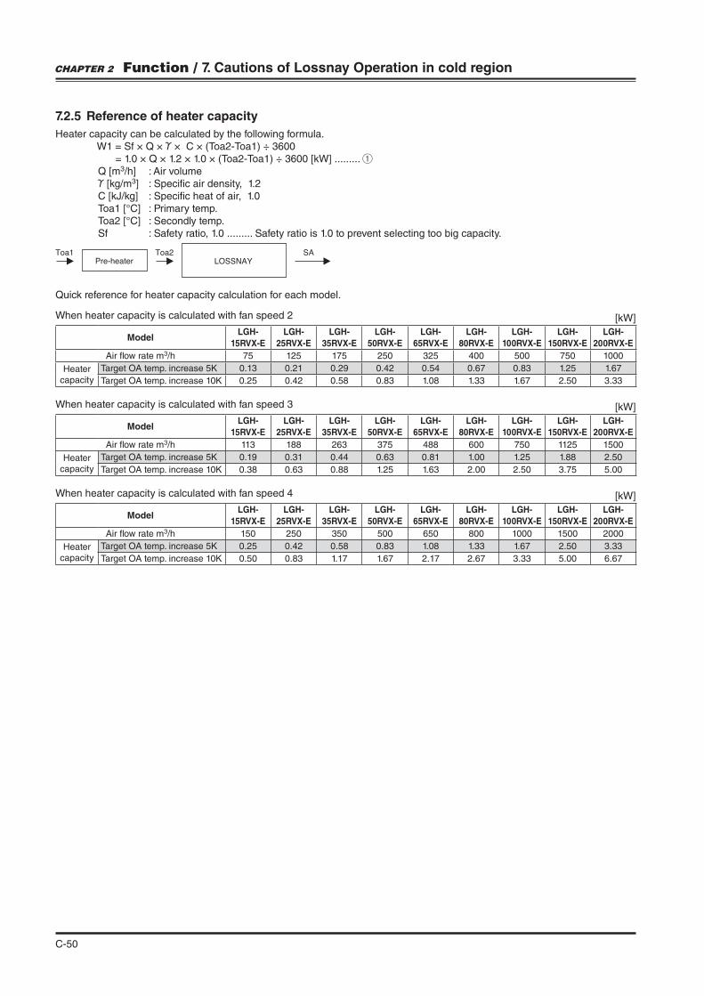
C-50
7.2.5 Reference of heater capacity
Heater capacity can be calculated by the following formula. W1 = Sf × Q × × C × (Toa2-Toa1) ÷ 3600
3
3
Sf : Safety ratio, 1.0 ......... Safety ratio is 1.0 to prevent selecting too big capacity.
Pre-heaterToa2 SA
LOSSNAYToa1
CHAPTER 2 Function / 7. Cautions of Lossnay Operation in cold region
Quick reference for heater capacity calculation for each model.
When heater capacity is calculated with fan speed 2
When heater capacity is calculated with fan speed 3
When heater capacity is calculated with fan speed 4
ModelLGH-
15RVX-E
LGH-
25RVX-E
LGH-
35RVX-E
LGH-
50RVX-E
LGH-
65RVX-E
LGH-
80RVX-E
LGH-
100RVX-E
LGH-
150RVX-E
LGH-
200RVX-E
Air !ow rate m3/h 75 125 175 250 325 400 500 750 1000
Heatercapacity
0.13 0.21 0.29 0.42 0.54 0.67 0.83 1.25 1.67
0.25 0.42 0.58 0.83 1.08 1.33 1.67 2.50 3.33
ModelLGH-
15RVX-E
LGH-
25RVX-E
LGH-
35RVX-E
LGH-
50RVX-E
LGH-
65RVX-E
LGH-
80RVX-E
LGH-
100RVX-E
LGH-
150RVX-E
LGH-
200RVX-E
Air !ow rate m3/h 113 188 263 375 488 600 750 1125 1500
Heatercapacity
0.19 0.31 0.44 0.63 0.81 1.00 1.25 1.88 2.50
0.38 0.63 0.88 1.25 1.63 2.00 2.50 3.75 5.00
ModelLGH-
15RVX-E
LGH-
25RVX-E
LGH-
35RVX-E
LGH-
50RVX-E
LGH-
65RVX-E
LGH-
80RVX-E
LGH-
100RVX-E
LGH-
150RVX-E
LGH-
200RVX-E
Air !ow rate m3/h 150 250 350 500 650 800 1000 1500 2000
Heatercapacity
0.25 0.42 0.58 0.83 1.08 1.33 1.67 2.50 3.33
0.50 0.83 1.17 1.67 2.17 2.67 3.33 5.00 6.67
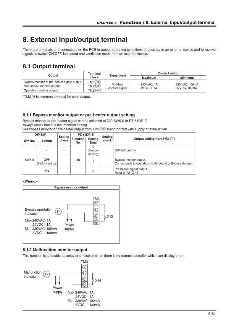
C-51
8. External Input/output terminal
There are terminals and connectors on the PCB to output operating conditions of Lossnay to an external device and to recieve signals to switch ON/OFF, fan speed and ventilation mode from an external device.
8.1 Output terminal
OutputTerminal
blockSignal form
Contact rating
Maximum Minimum
Bypass monitor or pre-heater signal output TM3Volt-free
contact signal240 VAC, 1A24 VDC, 1A
220 VAC, 100mA5 VDC, 100mA
Malfunction monitor output TM3
Operation monitor output TM3
8.1.1 Bypass monitor output or pre-heater output setting
Bypass monitor or pre-heater signal can be selected at DIP-SW5-6 or PZ-61DR-EAlways check that it is the intended setting.Set Bypass monitor or pre-heater output from TM3 synchronized with supply of exhaust fan.
*TM3 is common terminal for each output.
DIP-SWSetting check
PZ-61DR-ESetting check
Output setting from TM3SW No. Setting
Function No.
Setting Data
SW5-6
- -
58
0(Factory setting)
DIP-SW priority
OFF (Factory setting)
1Bypass monitor output. Corresponds to operation mode output of Bypass damper.
ON 2Pre-heater signal outputRefer to 7.2 (C-48)
CHAPTER 2 Function / 8. External Input/output terminal
Bypass monitor output
9
8
7
10
Bypass opertation
indicator
Power
supply
TM3
X13Max 240VAC, 1A
24VDC, 1A
Min 220VAC, 100mA
5VDC, 100mA
8.1.2 Malfunction monitor output
This function is to enable Lossnay error display when there is no remote controller which can display error.
9
8
7
10
Malfunction
indicator
Power
supply
TM3
X14
Max 240VAC, 1A
24VDC, 1A
Min 220VAC, 100mA
5VDC, 100mA
<Wiring>
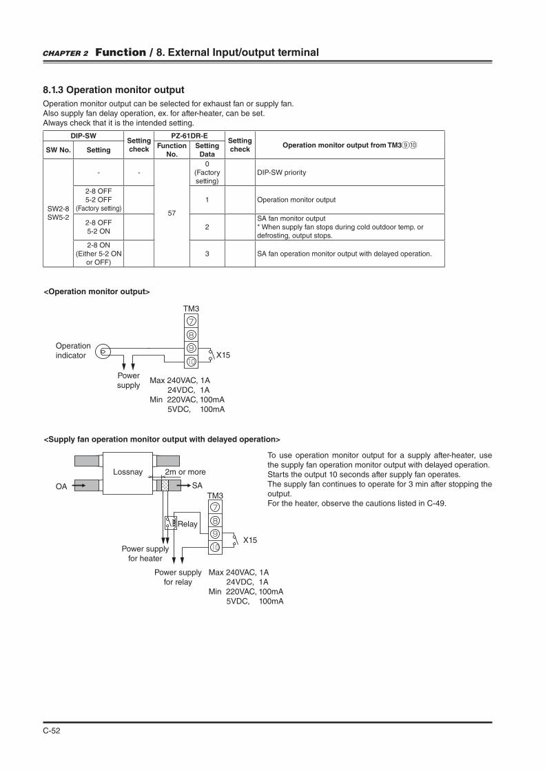
C-52
8.1.3 Operation monitor output
Operation monitor output can be selected for exhaust fan or supply fan.Also supply fan delay operation, ex. for after-heater, can be set. Always check that it is the intended setting.
DIP-SWSetting check
PZ-61DR-ESetting check
Operation monitor output from TM3SW No. Setting
Function No.
Setting Data
SW2-8SW5-2
- -
57
0(Factory setting)
DIP-SW priority
2-8 OFF5-2 OFF
(Factory setting)1 Operation monitor output
2-8 OFF5-2 ON
2SA fan monitor output* When supply fan stops during cold outdoor temp. or defrosting, output stops.
2-8 ON(Either 5-2 ON
or OFF)3 SA fan operation monitor output with delayed operation.
<Operation monitor output>
<Supply fan operation monitor output with delayed operation>
9
8
7
10
Operation
indicator
Power
supply
TM3
X15
Max 240VAC, 1A
24VDC, 1A
Min 220VAC, 100mA
5VDC, 100mA
Lossnay
Power supply
for heater
Power supply
for relay
X15
Relay
TM3OA SA
2m or more
9
8
7
10
Max 240VAC, 1A
24VDC, 1A
Min 220VAC, 100mA
5VDC, 100mA
To use operation monitor output for a supply after-heater, use the supply fan operation monitor output with delayed operation.Starts the output 10 seconds after supply fan operates.The supply fan continues to operate for 3 min after stopping the output.For the heater, observe the cautions listed in C-49.
CHAPTER 2 Function / 8. External Input/output terminal

C-53
SW1: When this is ON, Lossnay cannot turn ON/OFF by the remote controller or centralized controller.
SW2: When SW1 is ON, Lossnay can be turned ON by setting SW2 at ON or turned OFF by setting SW2 at OFF.
SW1: Remote/local selector switchSW2: ON/OFF switchX, Y : Relay (Contactor rating minimum
applicable load DC 1 mA)
8.2 Input terminal
8.2.1 ON/OFF switching by using CN32 (When using the remote/local switching and the ON/OFF input)
Use when intending to prohibit switching ON/OFF from remote controller or centralized controller.In the case of using 2 switches ("eld supply) for ON/OFF
In the case of forcing stop
CN32
SW1
SW2
Y
X
Y
X
Remote control
board
Re
lay p
ow
er
su
pp
ly
Lossnay
control board
Remote ON/OFF adaptor
(Optional)PAC-SE55RA-ERelay circuit
Orange 1
Max wiring length 10m
Red 2
Brown 3
Note;Cannot use together with external input signal by TM2.When using in a group of multiple Lossnay units, be sure to connect to main unit. Refer to page C-9.Connect the TM4 of each Lossnay unit.In the case that Lossnay is connected to MELANS, operation lock from system controller has a priority.
CN32
SW1
Insulatecompletely
e.g. Fire alarm
(closed when emergency) Lossnay PCBRemote ON/OFF adaptor
(Optional)PAC-SE55RA-E
Orange 1
Max wiring length 10m
Red 2
Brown 3
CHAPTER 2 Function / 8. External Input/output terminal
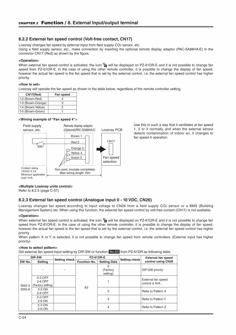
C-54
Use this in such a way that it ventilates at fan speed 1, 2 or 3 normally, and when the external sensor detects contamination of indoor air, it changes to fan speed 4 operation.
<Multiple Lossnay units control>Refer to 8.2.5 (page C-57)
8.2.2 External fan speed control (Volt-free contact, CN17)
Lossnay changes fan speed by external input from "eld supply CO2 sensor, etc.Using a "eld supply sensor, etc., make connection by inserting the optional remote display adaptor (PAC-SA88HA-E) in the connector CN17 (Red) as shown by the "gure.
CN17(Red) Fan speed
1-2 (Brown-Red) 4
1-3 (Brown-Orange) 3
2
1-5 (Brown-Green) 1
SW1
CN17
Field supply
sensor, etc.
Contact rating
15VDC 0.1A
Minimum applicable
load 1mA
Lossnay PCB
Fan speed
selection
Remote display adaptor
(Optional)PAC-SA88HA-E
Brown 1
Orange 3
Yellow 4
Green 5
Max wiring length 10mNot used. Insulate completely.
Red 2
<Operation>
When external fan speed control is activated, the icon will be displayed on PZ-61DR-E and it is not possible to change fan speed from PZ-61DR-E. In the case of using the other remote controller, it is possible to change the display of fan speed, however the actual fan speed is the fan speed that is set by the external control, i.e. the external fan speed control has higher priority.
<How to set>
Lossnay will operate the fan speed as shown in the table below, regardless of the remote controller setting.
<Wining example of “Fan speed 4”>
CHAPTER 2 Function / 8. External Input/output terminal
8.2.3 External fan speed control (Analogue input 0 - 10 VDC, CN26)
Lossnay changes fan speed according to input voltage to CN26 from a field supply CO2 sensor or a BMS (Building Management System) etc. When using this function, the external fan speed control by volt-free contact (CN17) is not available.
<Operation>
When external fan speed control is activated, the icon will be displayed on PZ-61DR-E and it is not possible to change fan speed from PZ-61DR-E. In the case of using the other remote controller, it is possible to change the display of fan speed, however the actual fan speed is the fan speed that is set by the external control, i.e. the external fan speed control has higher priority.
priority)
<How to select pattern> Set external fan speed input setting by DIP-SW or function No.63 from PZ-61DR as following table.
DIP-SWSetting check
PZ-61DR-ESetting check
External fan speed control using CN26SW No. Setting Function No. Setting Data
SW2-3SW2-6
- -
63
0(Factory setting)
DIP-SW priority
2-3 OFF2-6 OFF
(Factory setting)1
External fan speed control is N/A.
2-3 ON2-6 OFF
2 Refer to Pattern X
2-3 OFF2-6 ON
3
2-3 ON2-6 ON
4 Refer to Pattern Z
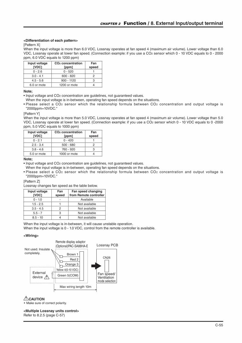
C-55
CHAPTER 2 Function / 8. External Input/output terminal
<Wiring>
CN26
External
device
Lossnay PCB
Fan speed/Ventilationmode selection
Remote display adaptor
(Optional)PAC-SA88HA-E
Brown 1
Orange 3
Yellow 4(0-10 VDC)
Green 5(COM)
Max wiring length 10m
Not used. Insulate
completely.
Red 2
CAUTION
<Differentiation of each pattern>
When the input voltage is more than 6.0 VDC, Lossnay operates at fan speed 4 (maximum air volume). Lower voltage than 6.0 VDC, Lossnay operate at lower fan speed. (Connection example: if you use a CO2 sensor which 0 - 10 VDC equals to 0 - 2000 ppm, 6.0 VDC equals to 1200 ppm)
When the input voltage is more than 5.0 VDC, Lossnay operates at fan speed 4 (maximum air volume). Lower voltage than 5.0 VDC, Lossnay operate at lower fan speed. (Connection example: if you use a CO2 sensor which 0 - 10 VDC equals to 0 -2000 ppm, 5.0 VDC equals to 1000 ppm)
Lossnay changes fan speed as the table below.
When the input voltage is in-between, it will cause unstable operation.When the input voltage is 0 - 1.0 VDC, control from the remote controller is available.
Note;2 concentration are guidelines, not guaranteed values.
When the input voltage is in-between, operating fan speed depends on the situations.2 sensor which the relationship formula between CO2 concentration and output voltage is
Note;2 concentration are guidelines, not guaranteed values.
When the input voltage is in-between, operating fan speed depends on the situations.2 sensor which the relationship formula between CO2 concentration and output voltage is
Input voltage [VDC]
Fan speed
Fan speed changing from Remote controller
0 - 1.0 - Available
1.5 - 2.5 1 Not available
3.5 - 4.5 2 Not available
5.5 - 7 3 Not available
8.5 - 10 4 Not available
Input voltage [VDC]
CO2 concentration [ppm]
Fan speed
0 - 2.6 0 - 520 1
3.0 - 4.1 600 - 820 2
4.5 - 5.6 900 - 1120 3
6.0 or mote 1200 or mote 4
Input voltage [VDC]
CO2 concentration [ppm]
Fan speed
0 - 2.1 0 - 420 1
2.5 - 3.4 500 - 680 2
3.8 - 4.6 760 - 920 3
5.0 or mote 1000 or mote 4
<Multiple Lossnay units control>Refer to 8.2.5 (page C-57)
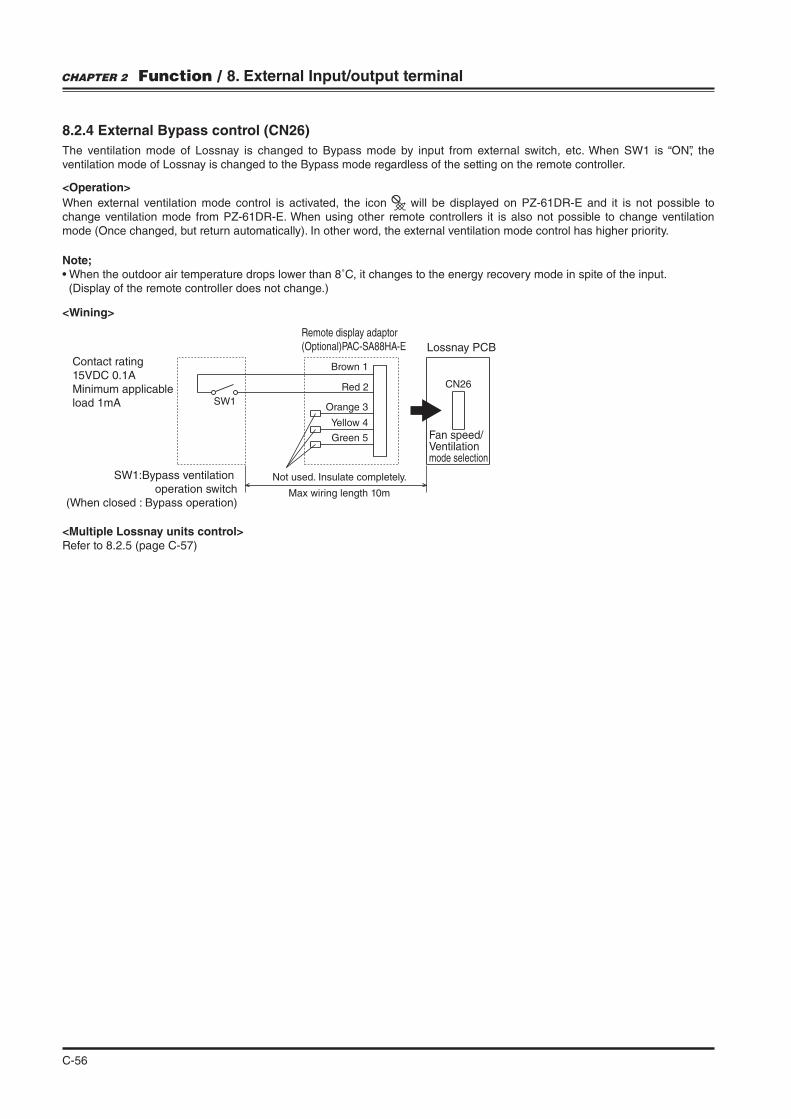
C-56
8.2.4 External Bypass control (CN26)
The ventilation mode of Lossnay is changed to Bypass mode by input from external switch, etc. When SW1 is “ON”, the ventilation mode of Lossnay is changed to the Bypass mode regardless of the setting on the remote controller.
<Wining>
SW1
CN26
Contact rating
15VDC 0.1A
Minimum applicable
load 1mA
SW1:Bypass ventilation
operation switch
(When closed : Bypass operation)
Lossnay PCB
Fan speed/Ventilationmode selection
Remote display adaptor
(Optional)PAC-SA88HA-E
Brown 1
Orange 3
Yellow 4
Green 5
Max wiring length 10m
Not used. Insulate completely.
Red 2
Note;
(Display of the remote controller does not change.)
<Operation>
When external ventilation mode control is activated, the icon will be displayed on PZ-61DR-E and it is not possible to change ventilation mode from PZ-61DR-E. When using other remote controllers it is also not possible to change ventilation mode (Once changed, but return automatically). In other word, the external ventilation mode control has higher priority.
CHAPTER 2 Function / 8. External Input/output terminal
<Multiple Lossnay units control>Refer to 8.2.5 (page C-57)

C-57
Note; To control sub units by one CO2 sensor, PZ-61DR-E is necessary.
<Caution>
Some mulfunction will occur.
8.2.5 Sub unit setting (Multiple Lossnay units control by external input)
When using PZ-61DR-E, it is necessary for sub unit to select 'Main unit input priority' or 'Individual input priority'. This function is available to the following external input; -External fan speed control (CN17 and CN26) -External Bypass control (CN26)When not using PZ-61DR-E, sub unit does not follow the main unit. See the case 3 below.
DIP-SWSetting check
PZ-61DR-ESetting check
Input priority settingSW No. Setting
Function No.
Setting Data
N/A- -
34
0(Factory setting)
Main unit input priority
- - 1 Individual input priority
Sub units follow the main unit
DO NOT make a system like below.
Sub 1 unit follows the individual input from CO2 sensor, sub 2 unit follows the main unit
Sub units do not follow the main unit
PZ-61DR-E
Field supply(CO2 sensor,
BMS etc.)
(Main) (Sub : Main priority)(Sub : Main priority)
PZ-61DR-E
Field supply(CO2 sensor,
BMS etc.)
PZ-43SMF-E
No remote controller
PZ-61DR-E
Field supply(CO2 sensor,
BMS etc.)
(Main) (Sub 1 : Individual priority)(Sub 2 : Main priority)
Field supply(CO2 sensor,
BMS etc.)
PZ-43SMF-Eor
no remote controller
(Main) (Sub : Either main / individual priority)
<How to set>
<Usage examples>
CHAPTER 2 Function / 8. External Input/output terminal
Case 1
Case 2
Case 3
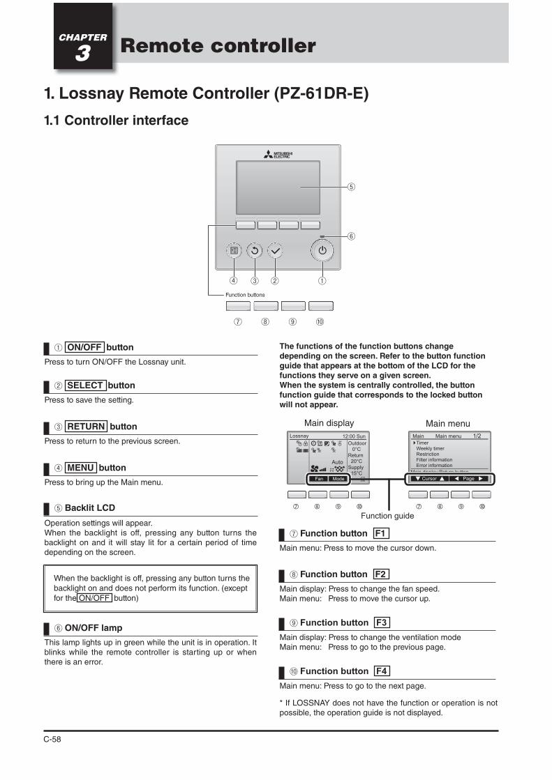
C-58
Remote controllerCHAPTER
3
Function buttons
Press to turn ON/OFF the Lossnay unit.
ON/OFF button
This lamp lights up in green while the unit is in operation. It blinks while the remote controller is starting up or when there is an error.
Press to save the setting.
Main menu: Press to move the cursor down.
Press to return to the previous screen.
Main display: Press to change the fan speed.Main menu: Press to move the cursor up.
Press to bring up the Main menu.
Main display: Press to change the ventilation modeMain menu: Press to go to the previous page.
Operation settings will appear.When the backlight is off, pressing any button turns the backlight on and it will stay lit for a certain period of time depending on the screen.
Main menu: Press to go to the next page.
possible, the operation guide is not displayed.
ON/OFF lamp
SELECT button
Function button F1
RETURN button
Function button F2
MENU button
Function button F3
Backlit LCD
Function button F4
When the backlight is off, pressing any button turns the
backlight on and does not perform its function. (except
for the ON/OFF button)
Main
Main display:Return button
Cursor Page
Main menu
TimerWeekly timerRestrictionFilter informationError information
1/2Lossnay 12:00 Sun
Outdoor 0°C
Return 20°C
Supply 15°C
Fan Mode
Auto
The functions of the function buttons change depending on the screen. Refer to the button function guide that appears at the bottom of the LCD for the functions they serve on a given screen.When the system is centrally controlled, the button function guide that corresponds to the locked button will not appear.
Main display Main menu
Function guide
1. Lossnay Remote Controller (PZ-61DR-E)
1.1 Controller interface
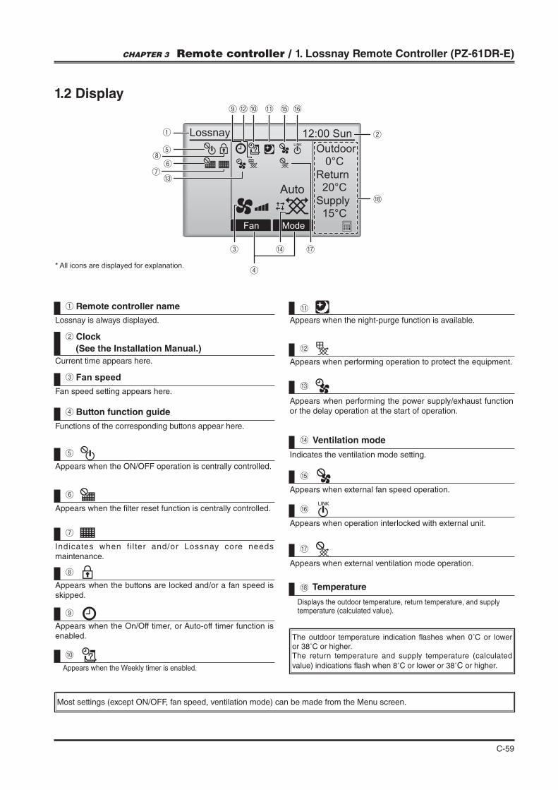
C-59
Lossnay 12:00 Sun
Outdoor 0°C
Return 20°C
Supply 15°C
Fan Mode
Auto
* All icons are displayed for explanation.
Fan speed setting appears here.
Fan speed
Appears when the night-purge function is available.
Appears when performing operation to protect the equipment.
Appears when the ON/OFF operation is centrally controlled.
Current time appears here.
Appears when the buttons are locked and/or a fan speed is skipped.
Lossnay is always displayed.
Remote controller name
Indicates the ventilation mode setting.
Ventilation mode
Appears when external fan speed operation.
Appears when operation interlocked with external unit.
Appears when the On/Off timer, or Auto-off timer function is enabled.
Indicates when fi l ter and/or Lossnay core needs maintenance.
Appears when the "lter reset function is centrally controlled.
Appears when the Weekly timer is enabled.
Appears when external ventilation mode operation.
Displays the outdoor temperature, return temperature, and supply
Temperature
Functions of the corresponding buttons appear here.
Button function guideAppears when performing the power supply/exhaust function or the delay operation at the start of operation.
The outdoor temperature indication !ashes when 0˚C or lower or 38˚C or higher.The return temperature and supply temperature (calculated
value) indications !ash when 8˚C or lower or 38˚C or higher.
Clock
(See the Installation Manual.)
Most settings (except ON/OFF, fan speed, ventilation mode) can be made from the Menu screen.
1.2 Display
CHAPTER 3 Remote controller / 1. Lossnay Remote Controller (PZ-61DR-E)
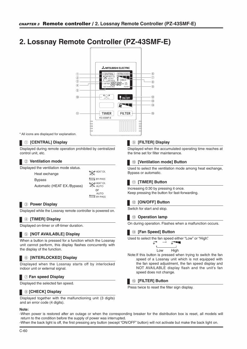
C-60
2. Lossnay Remote Controller (PZ-43SMF-E)
Note:- When power is restored after an outage or when the corresponding breaker for the distribution box is reset, all models will return to the condition before the supply of power was interrupted.
- When the back light is off, the "rst pressing any button (except “ON/OFF” button) will not activate but make the back light on.
Displayed during remote operation prohibited by centralized control unit, etc.
Displayed when the accumulated operating time reaches at the time set for "lter maintenance.
Used to select the ventilation mode among heat exchange, Bypass or automatic.
Increasing 0:30 by pressing it once.
Switch for start and stop.
On during operation. Flashes when a malfunction occurs.
Press twice to reset the "lter sign display.
Used to select the fan speed either “Low” or “High”.
Low HighNote: If this button is pressed when trying to switch the fan
speed of a Lossnay unit which is not equipped with the fan speed adjustment, the fan speed display and NOT AVAILABLE display flash and the unit's fan speed does not change.
Displayed the ventilation mode status.
Heat exchange
Bypass
Automatic (HEAT EX./Bypass) or
Displayed while the Lossnay remote controller is powered on.
Displayed on-timer or off-timer duration.
When a button is pressed for a function which the Lossnay unit cannot perform, this display !ashes concurrently with the display of the function.
Displayed the selected fan speed.
Displayed when the Lossnay starts off by interlocked indoor unit or external signal.
Displayed together with the malfunctioning unit (3 digits) and an error code (4 digits).
[CENTRAL] Display [FILTER] Display
[Ventilation mode] Button
[TIMER] Button
[ON/OFF] Button
Operation lamp
[FILTER] Button
[Fan Speed] Button
Ventilation mode
Power Display
[TIMER] Display
[NOT AVAILABLE] Display
Fan speed Display
[INTERLOCKED] Display
[CHECK] Display
* All icons are displayed for explanation.
CHAPTER 3 Remote controller / 2. Lossnay Remote Controller (PZ-43SMF-E)
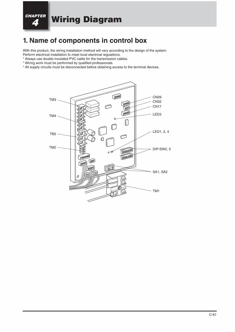
C-61
Wiring DiagramCHAPTER
4
1. Name of components in control box
With this product, the wiring installation method will vary according to the design of the system.Perform electrical installation to meet local electrical regulations.* Always use double insulated PVC cable for the transmission cables.* Wiring work must be performed by quali" ed professionals.* All supply circuits must be disconnected before obtaining access to the terminal devices.
TM1
LED3
CN17
CN32
CN26
LED1, 2, 4
DIP-SW2, 5
SA1, SA2
TM3
TB5
TM2
TM4
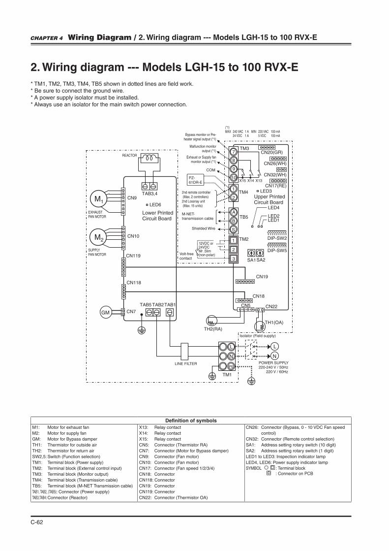
C-62
7
8
9
10
S
A
B
1
2
1
2
N
L
N
PE
L
M1
M2
GM CN7
CN118
CN119
CN10
CN9
LED6
TAB3,4
TAB2TAB5 TAB1
TH1(OA)
TH2(RA)
TM1
CN19
CN18
CN22CN5
SA2SA1
DIP-SW5
DIP-SW2
3
TM2
TB5
TM4
TM3
PZ-
61DR-E
CN26(WH)
CN20(GR)
CN32(WH)
CN17(RE)LED3
LED4
LED2LED1
2. Wiring diagram --- Models LGH-15 to 100 RVX-E
* TM1, TM2, TM3, TM4, TB5 shown in dotted lines are "eld work.* Be sure to connect the ground wire.* A power supply isolator must be installed.* Always use an isolator for the main switch power connection.
Definition of symbols
M1: Motor for exhaust fan
M2: Motor for supply fan
GM: Motor for Bypass damper
TH1: Thermistor for outside air
TH2: Thermistor for return air
SW2,5: Switch (Function selection)
TM1: Terminal block (Power supply)
TM2: Terminal block (External control input)
TM3: Terminal block (Monitor output)
TM4: Terminal block (Transmission cable)
TB5: Terminal block (M-NET Transmission cable)
TAB1, TAB2, (TAB5): Connector (Power supply)
TAB3,TAB4: Connector (Reactor)
X13: Relay contact
X14: Relay contact
X15: Relay contact
CN5: Connector (Thermistor RA)
CN7: Connector (Motor for Bypass damper)
CN9: Connector (Fan motor)
CN10: Connector (Fan motor)
CN17: Connector (Fan speed 1/2/3/4)
CN18: Connector
CN118: Connector
CN19: Connector
CN119: Connector
CN22: Connector (Thermistor OA)
CN26: Connector (Bypass, 0 - 10 VDC Fan speed
control)
CN32: Connector (Remote control selection)
SA1: Address setting rotary switch (10 digit)
SA2: Address setting rotary switch (1 digit)
LED1 to LED3: Inspection indicator lamp
LED4, LED6: Power supply indicator lamp
: Terminal block : Connector on PCB
FAN MOTOR
REACTOR
EXHAUST FAN MOTOR
Bypass monitor or Pre-heater signal output (*1)
Malfunction monitor output (*1)
Exhaust or Supply fan monitor output (*1)
12VDC or 24VDCMr .Slim (non-polar)Volt-free
contact
M-NET-transmission cable
2nd remote controller (Max. 2 controllers)2nd Lossnay unit (Max. 15 units)
(*1)MAX 240 VAC 1 A MIN 220 VAC 100 mA 24 VDC 1 A 5 VDC 100 mA
Isolator (Field supply)
220-240 V / 50Hz 220 V / 60Hz
LINE FILTER
Shielded Wire
COM
Lower Printed Circuit Board
Upper Printed Circuit Board
X15 X14 X13
CHAPTER 4 Wiring Diagram / 2. Wiring diagram --- Models LGH-15 to 100 RVX-E
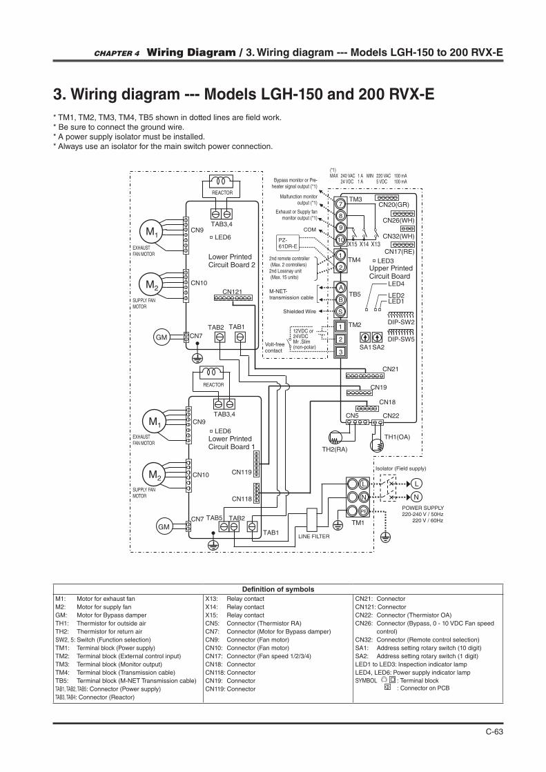
C-63
7
8
9
10
S
A
B
1
2
1
2
N
L
N
PE
L
M1
M2
GMCN7
CN118
CN119CN10
CN9TAB3,4
TAB2
TAB1
TH1(OA)
TH2(RA)
TM1
CN19
CN18
CN22CN5
SA2SA1
DIP-SW5
DIP-SW2
3
TM2
TB5
TM4
X15 X14 X13
TM3
PZ-
61DR-E
TAB5
M1
M2
GM CN7
CN10
CN9TAB3,4
TAB2 TAB1
CN121
CN21
LED6
LED6
LED3
LED4
LED2LED1
CN26(WH)
CN20(GR)
CN32(WH)
CN17(RE)
3. Wiring diagram --- Models LGH-150 and 200 RVX-E
* TM1, TM2, TM3, TM4, TB5 shown in dotted lines are "eld work.* Be sure to connect the ground wire.* A power supply isolator must be installed.* Always use an isolator for the main switch power connection.
MOTOR
EXHAUST FAN MOTOR
MOTOR
EXHAUST FAN MOTOR
REACTOR
REACTOR
Bypass monitor or Pre-heater signal output (*1)
Malfunction monitor output (*1)
Exhaust or Supply fan monitor output (*1)
M-NET-transmission cable
2nd remote controller (Max. 2 controllers)2nd Lossnay unit (Max. 15 units)
(*1)MAX 240 VAC 1 A MIN 220 VAC 100 mA 24 VDC 1 A 5 VDC 100 mA
Isolator (Field supply)
Shielded Wire
COM
Lower Printed Circuit Board 2
Lower Printed Circuit Board 1
Upper Printed Circuit Board
LINE FILTER
Definition of symbols
M1: Motor for exhaust fan
M2: Motor for supply fan
GM: Motor for Bypass damper
TH1: Thermistor for outside air
TH2: Thermistor for return air
SW2, 5: Switch (Function selection)
TM1: Terminal block (Power supply)
TM2: Terminal block (External control input)
TM3: Terminal block (Monitor output)
TM4: Terminal block (Transmission cable)
TB5: Terminal block (M-NET Transmission cable)
TAB1, TAB2, TAB5: Connector (Power supply)
TAB3, TAB4: Connector (Reactor)
X13: Relay contact
X14: Relay contact
X15: Relay contact
CN5: Connector (Thermistor RA)
CN7: Connector (Motor for Bypass damper)
CN9: Connector (Fan motor)
CN10: Connector (Fan motor)
CN17: Connector (Fan speed 1/2/3/4)
CN18: Connector
CN118: Connector
CN19: Connector
CN119: Connector
CN21: Connector
CN121: Connector
CN22: Connector (Thermistor OA)
CN26: Connector (Bypass, 0 - 10 VDC Fan speed
control)
CN32: Connector (Remote control selection)
SA1: Address setting rotary switch (10 digit)
SA2: Address setting rotary switch (1 digit)
LED1 to LED3: Inspection indicator lamp
LED4, LED6: Power supply indicator lamp
: Terminal block : Connector on PCB
12VDC or 24VDCMr .Slim (non-polar)
Volt-free contact
220-240 V / 50Hz 220 V / 60Hz
CHAPTER 4 Wiring Diagram / 3. Wiring diagram --- Models LGH-150 to 200 RVX-E

January. 2015
Y14-003 Jan.2015 <MEE>