lotus service notes section khvsic.lotuscars.com/system/files/documents/sn_kh_cooling_elise...
TRANSCRIPT

Page 1
Lotus Service Notes Section KH
ENGINE COOLING
SECTION KH
Sub-Section Page
General Description KH.1 3
Maintenance KH.2 4
Drain/Refill Procedure KH.3 5
Radiator, Hoses & Cooling Fan KH.4 6
Radiator Fan Control KH.5 8
Radiator Feed & Return Pipes KH.6 10
Water Pump & Thermostat* Oil Coolers - All Powertrains KH.7 12
*See also 2ZZ/1ZZ engine repair manual; E120T0327J (Toyota publication) *See also 1ZR FAE engine repair CD; T000T1523F (Toyota production) *See also 2ZR FE engine repair CD; T000T1530F (Toyota production)
Updated 14th December 2012

Lotus Service Notes Section KH
Page 2
Coolant Flow Circuits
Thermostat closed Heater feed pipe in sill Throttle body Thermostat housing
Heater matrixin climate k74b
chamber Heater return Heater return pipe pipe in sill Heater feed from Header tank back of cylinder head
Radiator by-pass Recirculation pump
Thermostat open
Radiator on Radiator return pipe crash in chassis side railstructure
Throttle body thermostat
Heater matrix k74a
in climatechamber Return to thermostat housing Radiator feed pipe in chassis side rail Heater feed from back of cylinder head Header tank Recirculation pump
Page 3
Lotus Service Notes Section KH
KH.1 - GENERAL DESCRIPTION
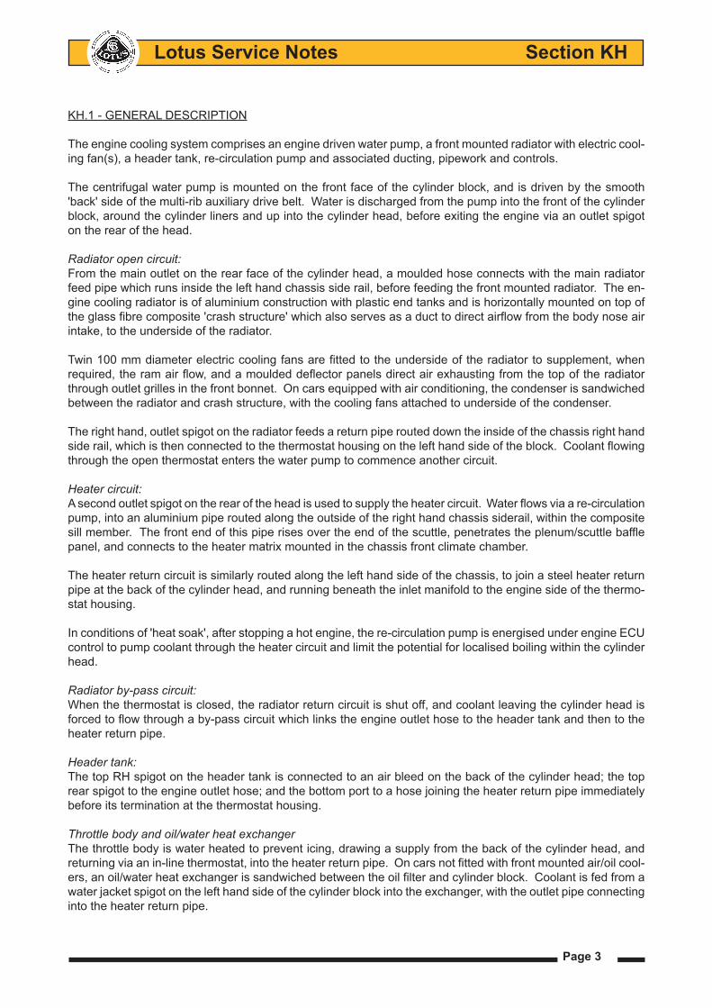
The engine cooling system comprises an engine driven water pump, a front mounted radiator with electric cool-ing fan(s), a header tank, re-circulation pump and associated ducting, pipework and controls.
The centrifugal water pump is mounted on the front face of the cylinder block, and is driven by the smooth 'back' side of the multi-rib auxiliary drive belt. Water is discharged from the pump into the front of the cylinder block, around the cylinder liners and up into the cylinder head, before exiting the engine via an outlet spigot on the rear of the head.
Radiator open circuit:From the main outlet on the rear face of the cylinder head, a moulded hose connects with the main radiator feed pipe which runs inside the left hand chassis side rail, before feeding the front mounted radiator. The en-gine cooling radiator is of aluminium construction with plastic end tanks and is horizontally mounted on top of the glass fibre composite 'crash structure' which also serves as a duct to direct airflow from the body nose air intake, to the underside of the radiator.
Twin 100 mm diameter electric cooling fans are fitted to the underside of the radiator to supplement, when required, the ram air flow, and a moulded deflector panels direct air exhausting from the top of the radiator through outlet grilles in the front bonnet. On cars equipped with air conditioning, the condenser is sandwiched between the radiator and crash structure, with the cooling fans attached to underside of the condenser.
The right hand, outlet spigot on the radiator feeds a return pipe routed down the inside of the chassis right hand side rail, which is then connected to the thermostat housing on the left hand side of the block. Coolant flowing through the open thermostat enters the water pump to commence another circuit.
Heater circuit:A second outlet spigot on the rear of the head is used to supply the heater circuit. Water flows via a re-circulation pump, into an aluminium pipe routed along the outside of the right hand chassis siderail, within the composite sill member. The front end of this pipe rises over the end of the scuttle, penetrates the plenum/scuttle baffle panel, and connects to the heater matrix mounted in the chassis front climate chamber.
The heater return circuit is similarly routed along the left hand side of the chassis, to join a steel heater return pipe at the back of the cylinder head, and running beneath the inlet manifold to the engine side of the thermo-stat housing.
In conditions of 'heat soak', after stopping a hot engine, the re-circulation pump is energised under engine ECU control to pump coolant through the heater circuit and limit the potential for localised boiling within the cylinder head.
Radiator by-pass circuit:When the thermostat is closed, the radiator return circuit is shut off, and coolant leaving the cylinder head is forced to flow through a by-pass circuit which links the engine outlet hose to the header tank and then to the heater return pipe.
Header tank:The top RH spigot on the header tank is connected to an air bleed on the back of the cylinder head; the top rear spigot to the engine outlet hose; and the bottom port to a hose joining the heater return pipe immediately before its termination at the thermostat housing.
Throttle body and oil/water heat exchanger The throttle body is water heated to prevent icing, drawing a supply from the back of the cylinder head, and returning via an in-line thermostat, into the heater return pipe. On cars not fitted with front mounted air/oil cool-ers, an oil/water heat exchanger is sandwiched between the oil filter and cylinder block. Coolant is fed from a water jacket spigot on the left hand side of the cylinder block into the exchanger, with the outlet pipe connecting into the heater return pipe.
Page 4
Lotus Service Notes Section KH
KH.2 - MAINTENANCE
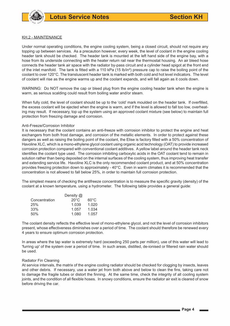
Under normal operating conditions, the engine cooling system, being a closed circuit, should not require any topping up between services. As a precaution however, every week, the level of coolant in the engine cooling header tank should be checked. The header tank is mounted at the left hand side of the engine bay, with a hose from its underside connecting with the heater return rail near the thermostat housing. An air bleed hose connects the header tank air space with the radiator by-pass circuit and a cylinder head spigot at the front end of the inlet manifold. The tank is fitted with a 110 kPa (15 lb/in²) pressure cap to raise the boiling point of the coolant to over 120°C. The transluscent header tank is marked with both cold and hot level indicators. The level of coolant will rise as the engine warms up and the coolant expands, and will fall again as it cools down. WARNING: Do NOT remove the cap or bleed plug from the engine cooling header tank when the engine is warm, as serious scalding could result from boiling water and/or steam.
When fully cold, the level of coolant should be up to the ‘cold’ mark moulded on the header tank. If overfilled, the excess coolant will be ejected when the engine is warm, and if the level is allowed to fall too low, overheat-ing may result. If necessary, top up the system using an approved coolant mixture (see below) to maintain full protection from freezing damage and corrosion.
Anti-Freeze/Corrosion InhibitorIt is necessary that the coolant contains an anti-freeze with corrosion inhibitor to protect the engine and heat exchangers from both frost damage, and corrosion of the metallic elements. In order to protect against these dangers as well as raising the boiling point of the coolant, the Elise is factory filled with a 50% concentration of Havoline XLC, which is a mono-ethylene glycol coolant using organic acid technology (OAT) to provide increased corrosion protection compared with conventional coolant additives. A yellow label around the header tank neck identifies the coolant type used. The corrosion inhibiting carboxylic acids in the OAT coolant tend to remain in solution rather than being deposited on the internal surfaces of the cooling system, thus improving heat transfer and extending service life. Havoline XLC is the only recommended coolant product, and at 50% concentration provides freezing protection down to approximately - 40°C. Even in warm climates it is recommended that the concentration is not allowed to fall below 25%, in order to maintain full corrosion protection.
The simplest means of checking the antifreeze concentration is to measure the specific gravity (density) of the coolant at a known temperature, using a hydrometer. The following table provides a general guide:
Density @Concentration 20°C 60°C25% 1.039 1.02033% 1.057 1.03450% 1.080 1.057
The coolant density reflects the effective level of mono-ethylene glycol, and not the level of corrosion inhibitors present, whose effectiveness diminishes over a period of time. The coolant should therefore be renewed every 4 years to ensure optimum corrosion protection.
In areas where the tap water is extremely hard (exceeding 250 parts per million), use of this water will lead to 'furring up' of the system over a period of time. In such areas, distilled, de-ionised or filtered rain water should be used.
Radiator Fin CleaningAt service intervals, the matrix of the engine cooling radiator should be checked for clogging by insects, leaves and other debris. If necessary, use a water jet from both above and below to clean the fins, taking care not to damage the fragile tubes or distort the finning. At the same time, check the integrity of all cooling system joints, and the condition of all flexible hoses. In snowy conditions, ensure the radiator air exit is cleared of snow before driving the car.

Page 5
Lotus Service Notes Section KH
KH.3 - DRAIN/REFILL PROCEDURE
To drain the engine cooling system:
Remove the front and rear undertrays - see service notes introduction section for further information.1.
Disconnect the radiator feed and return hoses from the 2. front ends of the thro' chassis pipes, and collect the draining coolant using a suitable container. Remove the header tank cap to speed the operation.
Open the drain tap on the engine coolant drain union 3. at the right hand rear of the cylinder block and drain the coolant.For 2ZZ/1ZZ powertrains see engine repair manual; E120T0327J section CO for further information. For ZR FAE powertrains see engine repair CD; T000T1523F For 2ZR FE powertrains see engine repair CD; T000T1530F
Note that draining of the heater matrix is not easily possible with the unit 'in situ', and that if draining for the purpose of coolant change, this volume should be disregarded.
To refill the system:
Refit the hoses to the feed and return pipes and close the cylinder block drain tap.•
Remove the right hand front wheelarch liner and open the air bleed plug on the radiator outlet hose. From •within the engine bay, open the air bleed plug in the heater return hose at the left hand rear of the engine bay.
Fill with the recommended coolant mix via the header tank and close the bleed plugs when a steady stream •of coolant is expelled.
Start the engine and allow to idle, and periodically open the bleed plugs to allow any trapped air to be expunged. Top up the header tank when necessary, and fit the pressure cap when required to prevent overflow. When the cooling fans have cut in and then out, stop the engine and allow to cool. Recheck coolant level when fully cold.
k83
Radiatorinlet hose(outlet hosepositioning onopposite sidesimilar
Chassis
Crash structure
k83
Radiatorinlet hoseair bleed
Updated 14th December 2012
Lotus Service Notes Section KH
Page 6
KH.4 - RADIATOR, HOSES & COOLING FAN
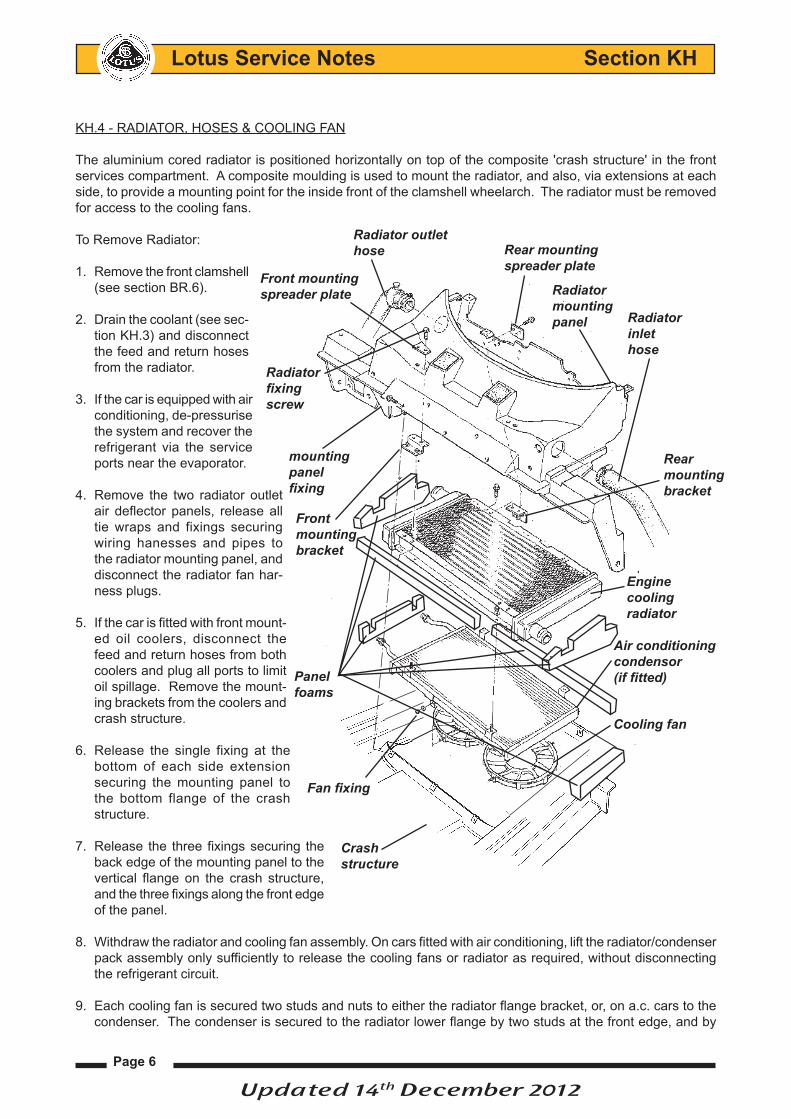
The aluminium cored radiator is positioned horizontally on top of the composite 'crash structure' in the front services compartment. A composite moulding is used to mount the radiator, and also, via extensions at each side, to provide a mounting point for the inside front of the clamshell wheelarch. The radiator must be removed for access to the cooling fans.
To Remove Radiator:
Remove the front clamshell 1. (see section BR.6).
Drain the coolant (see sec-2. tion KH.3) and disconnect the feed and return hoses from the radiator.
If the car is equipped with air 3. conditioning, de-pressurise the system and recover the refrigerant via the service ports near the evaporator.
Remove the two radiator outlet 4. air deflector panels, release all tie wraps and fixings securing wiring hanesses and pipes to the radiator mounting panel, and disconnect the radiator fan har-ness plugs.
If the car is fitted with front mount-5. ed oil coolers, disconnect the feed and return hoses from both coolers and plug all ports to limit oil spillage. Remove the mount-ing brackets from the coolers and crash structure.
Release the single fixing at the 6. bottom of each side extension securing the mounting panel to the bottom flange of the crash structure.
Release the three fixings securing the 7. back edge of the mounting panel to the vertical flange on the crash structure, and the three fixings along the front edge of the panel.
Withdraw the radiator and cooling fan assembly. On cars fitted with air conditioning, lift the radiator/condenser 8. pack assembly only sufficiently to release the cooling fans or radiator as required, without disconnecting the refrigerant circuit.
Each cooling fan is secured two studs and nuts to either the radiator flange bracket, or, on a.c. cars to the 9. condenser. The condenser is secured to the radiator lower flange by two studs at the front edge, and by
Rearmountingbracket
Radiatorinlethose
Front mountingspreader plate
Rear mountingspreader plate
Air conditioningcondensor (if fitted)
Frontmountingbracket
Fan fixing
Radiator mountingpanel
Cooling fan
Radiator outlethose
Crash structure
Radiator fixingscrew
mountingpanelfixing
Enginecoolingradiator
Panelfoams
Updated 14th December 2012
Page 7
Lotus Service Notes Section KH
two pairs of screws at the rear edge. The radiator is fixed to the mounting panel by brackets at the front and rear. Note the foam packing used between the radiator and mounting panel to ensure that all ducted air flows through the radiator matrix.
Refit the radiator in reverse order to removal except:
All bracket fixings tightened to 20Nm. •
Ensure that the foam packing is re-installed. •
Refill with coolant and bleed as detailed in sub-section KH.3. Re-charge refrigerant system - see service •notes section PL for further information.
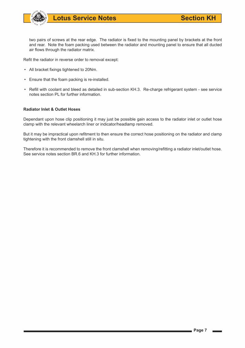
Radiator Inlet & Outlet Hoses
Dependant upon hose clip positioning it may just be possible gain access to the radiator inlet or outlet hose clamp with the relevant wheelarch liner or indicator/headlamp removed.
But it may be impractical upon refitment to then ensure the correct hose positioning on the radiator and clamp tightening with the front clamshell still in situ.
Therefore it is recommended to remove the front clamshell when removing/refitting a radiator inlet/outlet hose. See service notes section BR.6 and KH.3 for further information.

Lotus Service Notes Section KH
Page 8
KH.5 - RADIATOR FAN & RE-CIRC. PUMP CONTROL
The two cooling fans are fitted beneath the radiator or (with a.c.) condenser/radiator package, and the coolant re-circulation pump is mounted below the header tank. Both the fans and pump are controlled by the engine management ECU using data provided by the engine coolant temperature sensor mounted in the back of the cylinder head.
The cooling fans are switched as a pair, and will operate at half speed (connected in series) when coolant tem-perature reaches 98°C on rise, and switch off at 94°C on fall. The fans will also operate at half speed irrespective of coolant temperature if the a.c. is switched on and the compressor is running. If coolant temperature rises to 103°C, the fans will switch to full speed (connected in parallel), reverting to half speed at 98°C.
The fans will also run at half speed, unless high coolant temperature dictates otherwise, when the a.c. is switched on and the compressor is running, or if the engine management system detects a fault with the inlet air temperature or coolant temperature circuits.
At road speeds in excess of 85 mph (135 km/h), equating to the fan stall speed, all fan functions are switched off.
Heat SoakIn order to help control engine temperature after switch-ing off an engine whose temperature is over 88°C, the ECU will remain powered for a period of 20 minutes to allow heat soak management.
A coolant re-circulation electric pump is mounted below the coolant header tank and is plumbed into the heater supply line. When energised, the pump circulates coolant through the engine and heater system, drawing coolant from the back of the cylinder head, and pumping it through the heater matrix to the heater return pipe and back into the thermostat housing.
The pump functions only with ignition off in conditions where the ECU remains live. The pump is then acti-vated at coolant temperatures over 110°C, switching off at 100°C on fall. If temperature should rise to 115°C, the pump will be supplemented by the two cooling fans running at half speed, switching off at 110°C on fall.
Frontmountingbracket
Rearmountingbracket
Enginecooling radiator
RadiatormountingpanelCooling
fansA.Ccondensor
Frontspreaderplate
RADIATOR/CONDENSOR CROSS SECTION
P106
Outlet from pump to heater
Heater return hose Coolant re-circulation pump
Heater feed from cylinderhead
Coolantheader tank
P109b
Updated 14th December 2012

Page 9
Lotus Service Notes Section KH
Fan Control Module
The cooling fans, re-circ. pump and a.c. compressor are controlled by a relay module. The module is mounted to the top of the passenger side wheelarch liner on 2ZZ, 1ZZ powertrains (plus 1ZR powertrain using Kelsey Hayes ABS brake module) The module location was transferred to the RHS crash structure on the introduction of models using the Bosch ESP (Lotus DPM) brake module.
Important Note: The a.c. relay module is identical in appearance to the engine relay module, but the function of the two modules is different and they must not be transposed.
The a.c. relay module A117M0038F has a self adhesive label on its casing marked YWB100800 and a blue connector moulding; The engine relay module A111M6024F has a white or brown label marked YWB100970 and a black connector moulding. If necessary, use a scalpal blade to slim the centre spigot of a new module connector housing to allow its fitment on an earlier car.
If the ECM receives a signal voltage outside of the acceptable range, a default setting equating to 60°C will be substituted, and the cooling fan energised.
TRWYWB-100801
1311
Relay identification label
Location of cooling fan, re-circ. pump & a.c. compressor relay module on top of the wheelarch liner (2ZZ & 1ZZ engine)
Location of cooling fan, re-circ. pump & a.c. compressor relay module on the side of the crash structure (1ZR & 2ZR engine)
Updated 14th December 2012
Lotus Service Notes Section KH
Page 10
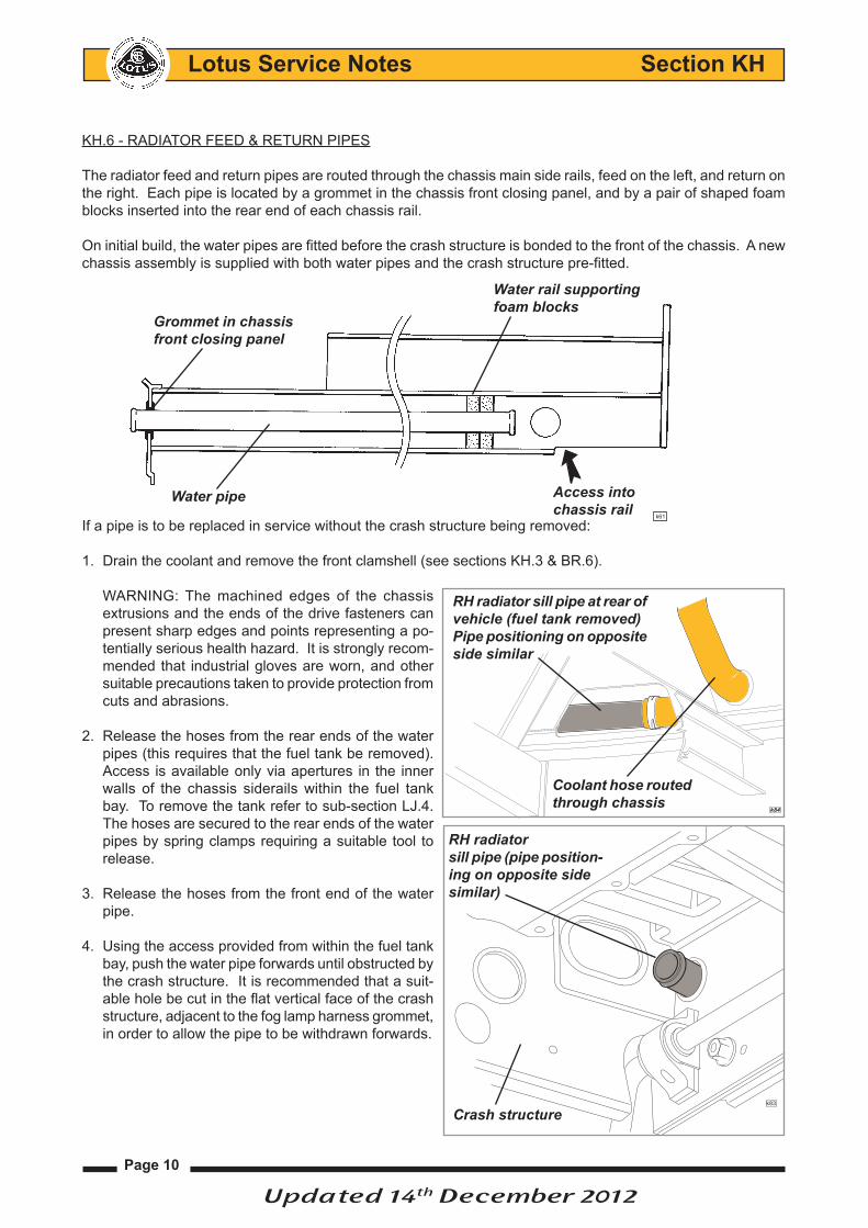
KH.6 - RADIATOR FEED & RETURN PIPES
The radiator feed and return pipes are routed through the chassis main side rails, feed on the left, and return on the right. Each pipe is located by a grommet in the chassis front closing panel, and by a pair of shaped foam blocks inserted into the rear end of each chassis rail.
On initial build, the water pipes are fitted before the crash structure is bonded to the front of the chassis. A new chassis assembly is supplied with both water pipes and the crash structure pre-fitted.
If a pipe is to be replaced in service without the crash structure being removed:
Drain the coolant and remove the front clamshell (see sections KH.3 & BR.6).1.
WARNING: The machined edges of the chassis extrusions and the ends of the drive fasteners can present sharp edges and points representing a po-tentially serious health hazard. It is strongly recom-mended that industrial gloves are worn, and other suitable precautions taken to provide protection from cuts and abrasions.
Release the hoses from the rear ends of the water 2. pipes (this requires that the fuel tank be removed). Access is available only via apertures in the inner walls of the chassis siderails within the fuel tank bay. To remove the tank refer to sub-section LJ.4. The hoses are secured to the rear ends of the water pipes by spring clamps requiring a suitable tool to release.
Release the hoses from the front end of the water 3. pipe.
Using the access provided from within the fuel tank 4. bay, push the water pipe forwards until obstructed by the crash structure. It is recommended that a suit-able hole be cut in the flat vertical face of the crash structure, adjacent to the fog lamp harness grommet, in order to allow the pipe to be withdrawn forwards.
k61
Grommet in chassis front closing panel
Water rail supportingfoam blocks
Access intochassis rail
Water pipe
RH radiatorsill pipe (pipe position-ing on opposite sidesimilar)
k83
Crash structure
RH radiator sill pipe at rear of vehicle (fuel tank removed) Pipe positioning on opposite side similar
Coolant hose routed through chassis
k84
Updated 14th December 2012

Page 11
Lotus Service Notes Section KH
To refit,Is the reversal of removal except:
Retrieve the two support foams from inside the chassis rail. Fit the grommet into the hole in the chassis •front closing plate, and smear with rubber grease. Feed the pipe through the access hole and grommet, and position with 35 - 40 mm of pipe protruding.
At the rear end of the pipe, fit two foam support blocks onto the pipe, and push into the chassis rail ahead •of the fuel tank bay aperture.
Refit the hoses to the front and rear ends of the pipes and manipulate the pipe to check for absence of •chassis contact 'knock'.
Blank off the access hole in the crash structure with a suitable grommet.•

Lotus Service Notes Section KH
Page 12
KH.7 - OIL COOLERS
1ZZ-FE Powertrain ('07MY - '10MY 1.8 Elise S)The engine utilises the original oil/water heat exchanger assembly fitted between the oil filter and housing to provide additional oil cooling. Front mounted oil coolers are not fitted to 1.6 engines.
1ZR-FAE Powertrain ('11MY Onwards 1.6 Elise)No external supplementary oil cooling is provided for 1ZR powertrain vehicles.
2ZZ Powertrain ('04MY - '11MY 1.8 Elise111R, R & Exige)Depending on market territory and date of build, cars may be fitted with either an engine mounted water/oil heat exchanger, or a single LH front mounted air/oil cooler, or twin front mounted air/oil coolers. The water/oil heat exchanger or single front mounted oil cooler is entirely adequate for all normal conditions of road use, but for cars used on closed circuit tracks or driven in a competitive manner (note; such use may invalidate vehicle warranty), or if full vehicle performance is to be exploited for an extended period (especially in hot ambient temperatures), it is recommended that twin front mounted coolers be fitted for optimum control of oil temperature.
Water/oil Heat Exchanger (if fitted)On cars so fitted, the oil/water heat exchanger is sandwiched between the oil filter and cylinder block. Water hoses connect a tapping on the left hand side of the cylinder block to the heat exchanger, and from the exchanger to the heater water return pipe. This device transfers heat from the engine coolant to the oil after a cold start, and conversely, in conditions of high oil temperature transfers heat from the oil to the coolant.
2ZR-FE Powertrain ('12MY 1.8 Elise S)Additional engine oil cooling is provided with the fitment of a single front mounted oil/air cooler radiator which is positioned to the right hand side of the engine cooling radiator ahead of the right hand front road wheel. Refer to page 25 onwards for additional information.
2ZZ Powertrain Oil Cooler Layout Oil cooler sandwich plate Cooler feed hose Oil cooler in RH sill thermostat
Heat exchanger Cooler hoses or by-pass mounting Cooler return hose plate in LH sill
Nut plates
Coolerinter- connectionhose
Air deflector panel LH oil cooler Oil/water heat exchanger
pl4603mt
Updated 14th December 2012
Page 13
Lotus Service Notes Section KH
Front Mounted Air/Oil CoolersOn cars so fitted, front mounted oil/air radiators are mounted ahead of each front wheel arch and fed withair from intakes either side of the main engine radiator intake in the body nose. 'Single oil cooler’ cars are equipped with an oil cooler ahead of only the LH front wheel, but use the same hoses as twin oil cooler cars, with a joiner union attached to a bracket in place of the symetrically opposite RH cooler.
On all cars with front mounted oil cooler(s), the oil/water heat exchanger is replaced by a sandwich plate incor-porating oil take-off feed and return unions, with the redundant coolant hoses interconnected by a 'U' pipe.
A thermostat incorporated into the sandwich plate begins to close at 72ºC, and is fully closed at 80ºC. When open, oil can by-pass the oil cooler circuit, but when fully closed, all oil is directed from the sandwich plate via a flexible hose within the RH sill panel, over the front wheel arch liner to the top connection on the RH oil cooler (or joiner union on single oil cooler cars).
From an outlet union at the bottom front of the cooler (or joiner union), another hose (transfer hose) runs be-neath the crash structure to the bottom of the LH cooler, from the top of which oil is returned via a third hose, running through the LH sill, back to the return union on the sandwich plate.
Procedure for conversion from single to twin front mounted oil coolers Parts Required Part Number QtyOil Cooler, RH, incl. foam seal A120K0020F 1Duct, oil cooler, RH - Elise A120B0090F 1 - Exige A122B0194F 1Big Head Pop Rivet, duct fixing A089W6297F 3
1. Remove the front clamshell (refer to sub-section BR.6).
Disconnect oil cooler hoses from joiner union ahead of RH front wheel using 2 off 1 1/8" spanners, and plug 2. hose ends to minimise oil loss.
Remove hose joiner bracket and secure new oil cooler, with its pre-applied sealing foam, to mounting bracket 3. using existing fixings. Torque tighten to 22 Nm.
Fit hoses to oil cooler. When tightening the union nut it is essential that the oil cooler union is held using a 4. 15/16 in. open end spanner whilst torque tightening the hose union nut (1 1/8") to 40 Nm. Failing to follow this procedure may result in damage to the oil cooler.
Start the engine and check for oil leaks.5.
Secure the new cooler duct with the three big head rivets to the radiator duct and refit the front clamshell.6.
Updated 14th December 2012

Lotus Service Notes Section KH
Page 14
Oil Cooler Circuit BleedingWhen carrying out routine oil changes, the oil quantity contained in the twin oil coolers and associated pipework is not disturbed and is considered perfectly satisfactory for routine maintenance operations.
In instances of major engine failure where the oil system may be contaminated with metallic debris, all oil cooler lines should be thoroughly flushed out and the oil cooler radiators replaced.
If the oil cooler circuit is drained or replaced, the following procedure should be adopted to fill the cooler system before starting the engine:
Attach a tube to the bleed nipple on the sandwich plate 1. between oil filter and engine block, and lead into a catch tank. Open the bleed nipple.
Disconnect the outlet hose from the top of the LH oil 2. cooler, and pour engine oil into the cooler until oil reaches the bleed nipple (approx. 2.5 litres). Close the bleed nipple, tightening to 8 Nm.
Connect the LH cooler outlet hose and tighten to 40 3. Nm.
Add a further 0.7 litres of oil into the engine to accom-4. modate the volume of the return hose between LH oil cooler and engine.
After starting the engine, restrict running to idle speed for 5. a minimum of 5 minutes, to allow the oil cooler lines to be purged of air. Stop engine and re-check oil level.
Sandwich plate bleed nipple
e228
Page 15
Lotus Service Notes Section KH
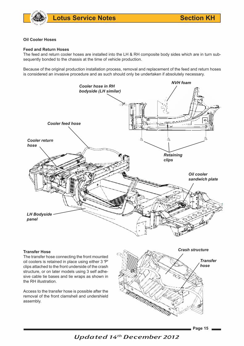
Oil Cooler Hoses
Feed and Return HosesThe feed and return cooler hoses are installed into the LH & RH composite body sides which are in turn sub-sequently bonded to the chassis at the time of vehicle production.
Because of the original production installation process, removal and replacement of the feed and return hoses is considered an invasive procedure and as such should only be undertaken if absolutely necessary.
Transfer HoseThe transfer hose connecting the front mounted oil coolers is retained in place using either 3 'P' clips attached to the front underside of the crash structure, or on later models using 3 self adhe-sive cable tie bases and tie wraps as shown in the RH illustration.
Access to the transfer hose is possible after the removal of the front clamshell and undershield assembly.
Right hand pipe run
This foam NVH fitted here.
Hose is fixed to bodyside by these 3 clips
4
Cooler hose in RHbodyside (LH similar)
NVH foam
Retaining clips
Cooler feed hose
Oil cooler sandwich plate
LH Bodysidepanel
Cooler returnhose
Crash structure
Transferhose
Updated 14th December 2012

Lotus Service Notes Section KH
Page 16
Feed & Return Hose Removal
(LH shown, RH similar)
Position vehicle on a suitable hoist, preferably 4 post or centre lift type - see service notes section AA.1 for 1. further information.
Remove LHF front wheel and wheelarch liner.2.
Remove LHF sill trim panel to gain access to oil hose & 3. front clip.
At the rear of the vehicle remove the engine bay undertray 4. - see Service Notes section AA.3 for further information.
From beneath the fuel tank, release the fixings securing the 5. 'shear panel' front and rear edges to the chassis, and those at each side securing the composite sills to the panel - see Service Notes section LJ.4 for further information.
Note that this panel is a structural part of the chassis, and the car should not be used without the panel fitted.
Release and remove the LH oil pipes connection from sand-6. wich plate/ thermostat assembly and drain the pipe into a suitable container. Before releasing the pipe from any clips and cable ties, note the position of these to assist in later replacement.
Disconnect LH hose from the oil cooler and pull away from it’s retain-7. ing clips located on the underside of the clamshell. Lower the hose to allow the oil to drain from the hose and cooler into suitable container(s) and plug the cooler port to minimize oil loss (you can use the caps supplied with new hose).
NOTE: Galvanic corrosion may occur between the oil hoses steel union nuts at their connection to the aluminium threads of the front mounted coolers, it is essential to apply a liberal quantity of a suit-able release agent around the area of the cooler unions before attempting to release them.
IMPORTANT: It is essential that the ‘flats’ on the base of the oil cooler union threaded connection are held using an open ended spanner whilst loosening the hose union nut. Failing to follow this procedure may result in damage to the oil cooler.
sb159
LH hose connection
Sandwich plate
Oil filter
RH hose connection
LH oil cooler hose
sb150
LH oil cooler
Lowerdash panel
'A' post trim removed ex-posing interior of bodyside and chassis sill Oil
cooler hose
e276
Updated 14th December 2012

Page 17
Lotus Service Notes Section KH
Remove oil hose to bodyside panel grommet and discard.8.
Release hose from its bodyside mounted clip 9.
Push pipe back through hole and pull through opening 10. in the sill.
The original oil cooler hose can now be used to route the replacement hose through the sill panel.
Old Hose Preparation Before Removing from the Bodyside Panel
Source a suitable thin flexible strong plastic material strap (such 11. as packing tape) ensuring that it is longer than the length of the bodyside sill.
Position one end of the plastic strap on the metal end of the oil 12. hose connector which is now protruding out of the bodyside sill. Secure the strap to the hose with a tie wrap as shown in the RH illustration ensuring that there is approximately 25mm - 1 inch of excess strip available.
e276
Lowerdash panel
Oil cooler hose
7
LH Hose Removal
1
•Disconnect oil cooler hoses from cooler union ahead of front wheel using an 28mm open end spanner.When releasing the union nut it is essential that the oil cooler union is held using a 24mm open endspanner. Drain oil lines into a suitable container and plug hose ends to minimise oil drips. (Use oil caps supplied with new hoses).
•Remove grommet (1) from oil pipe and discard.
•Release pipe from bodyside mounted clip (2).
•Push pipe back through hole and pull through opening in sill as shown in picture 3.
2
3
7
Oil cooler line hose shown through interior of bodyside panel
Hose bodysidepanel grommet
bodyside panel clips
Securing of Hose to pull through strap
Using13mm (1/2 inch) plastic packing strap position along oil pipe as shown in picture 1 and secure with cable tie.
1
2
3
Fold strap over cable tie andsecure with second cable tieas shown in picture 2.
Once strap is secure wrap with duct tape to hold in position as shown in picture 3.
8
Original hose stillin situ with pull strap fitted secured with a tie wrap
Updated 14th December 2012

Lotus Service Notes Section KH
Page 18
Fold excess length of strap over tie wrap and secure with second 13. tie wrap as shown in the RH illustration.
Once you have confirmed the strap is secure, wrap the strap 14. and the end of the hose with duct tape to hold in position as shown in LH illustration.
As shown on the LH illustration, the old hose will now have a secure strap attached to its connector that will be used to pull the new replacement hose through the bodyside sill panel.
With the aid of an assistant feed the hose through the bodyside panel whilst you pull the hose from the 15. rear.
If excessive resistance is experienced move the pipe in a sawing motion to overcome any resistance. The centre clip on the body side securing the pipe will probably break and come out with the pipe. This is ac-ceptable.
Securing of Hose to pull through strap
Using13mm (1/2 inch) plastic packing strap position along oil pipe as shown in picture 1 and secure with cable tie.
1
2
3
Fold strap over cable tie andsecure with second cable tieas shown in picture 2.
Once strap is secure wrap with duct tape to hold in position as shown in picture 3.
8
LH Hose Removal
9
With the aid of an assistant at the front, feed the pipe through whilst pulling the pipe from the rear.If excessive resistance is experienced move the pipe in a sawing motion to overcome any resistance.The centre clip on the body side securing the pipe will probably break and come out with the pipe. This is acceptable.
e276
Secu
ring
of H
ose
to p
ull t
hrou
gh s
trap
Usi
ng13
mm
(1/2
inch
) pla
stic
pac
king
str
ap p
ositi
on a
long
oil
pipe
as
show
n in
pic
ture
1 a
nd s
ecur
e w
ith c
able
tie.
1
2
3
Fold
str
ap o
ver
cabl
e tie
and
secu
re w
ith s
econ
d ca
ble
tie
as s
how
n in
pic
ture
2.
Onc
e st
rap
is s
ecur
e w
rap
with
duc
t tap
e to
hol
d in
posi
tion
as s
how
n in
pic
ture
3.
8
Tie-wraps andtape securingstrap to oil hose
Feed old hose through bodyside panel
Pull through strap
Updated 14th December 2012
Page 19
Lotus Service Notes Section KH
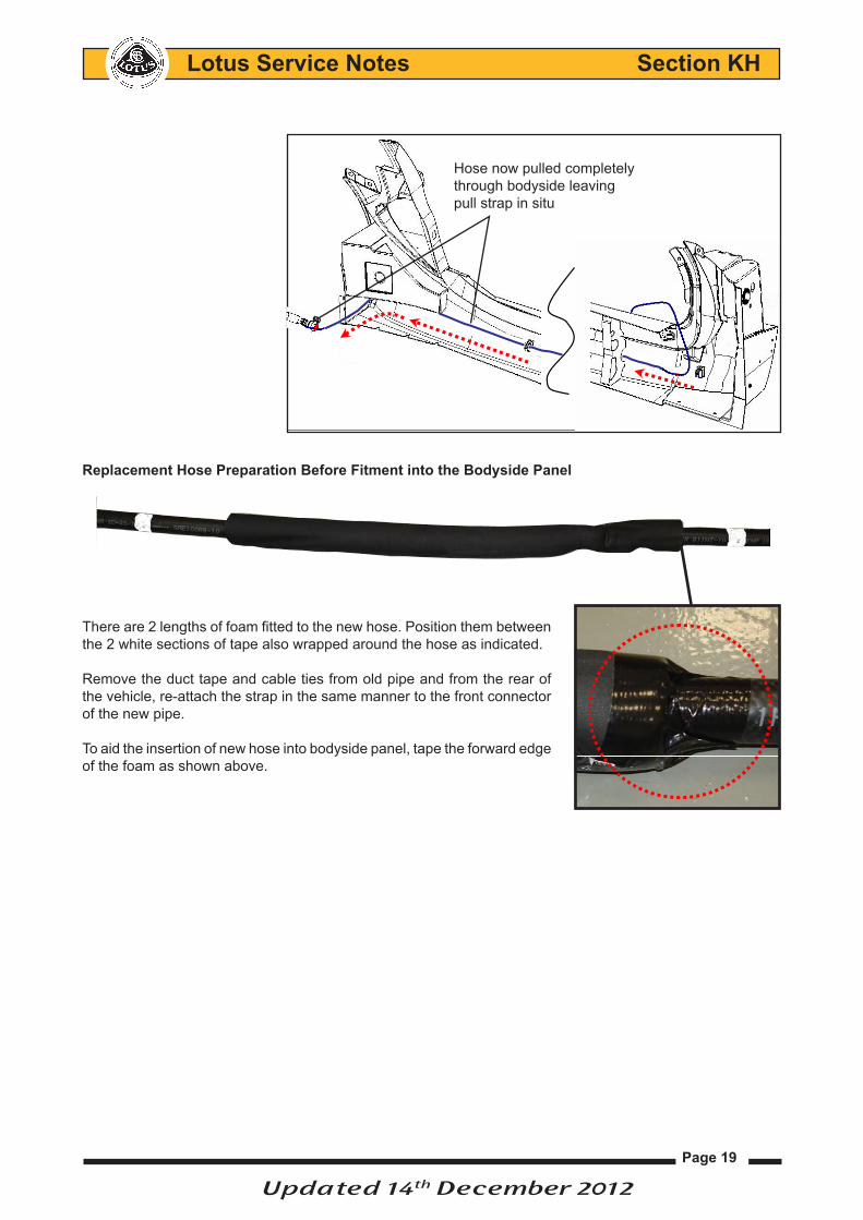
Replacement Hose Preparation Before Fitment into the Bodyside Panel
There are 2 lengths of foam fitted to the new hose. Position them between the 2 white sections of tape also wrapped around the hose as indicated.
Remove the duct tape and cable ties from old pipe and from the rear of the vehicle, re-attach the strap in the same manner to the front connector of the new pipe.
To aid the insertion of new hose into bodyside panel, tape the forward edge of the foam as shown above.
10
LH Hose Preparation
There are 2 lengths of foam fitted to the new pipe. Position between the white tape as indicated.Remove duct tape and cable ties from old pipe and re-attach strap to new pipe as detailed on page 8.
To aid insertion of pipe into bodyside, tape forward edge of foam as shown below.
LH Hose Removal
9
With the aid of an assistant at the front, feed the pipe through whilst pulling the pipe from the rear.If excessive resistance is experienced move the pipe in a sawing motion to overcome any resistance.The centre clip on the body side securing the pipe will probably break and come out with the pipe. This is acceptable.
Hose now pulled completely through bodyside leaving pull strap in situ
Updated 14th December 2012
Page 20
Lotus Service Notes Section KH
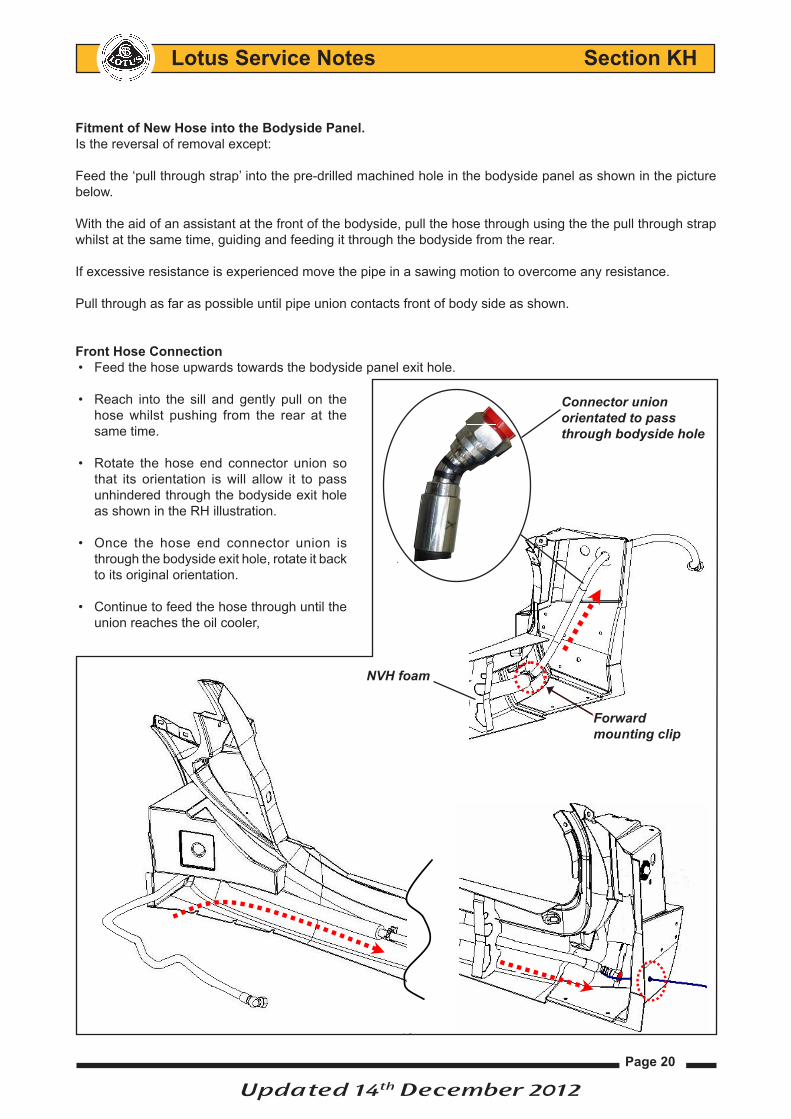
Fitment of New Hose into the Bodyside Panel.Is the reversal of removal except:
Feed the ‘pull through strap’ into the pre-drilled machined hole in the bodyside panel as shown in the picture below.
With the aid of an assistant at the front of the bodyside, pull the hose through using the the pull through strap whilst at the same time, guiding and feeding it through the bodyside from the rear.
If excessive resistance is experienced move the pipe in a sawing motion to overcome any resistance.
Pull through as far as possible until pipe union contacts front of body side as shown.
Front Hose ConnectionFeed the hose upwards towards the bodyside panel exit hole. •
Reach into the sill and gently pull on the •hose whilst pushing from the rear at the same time.
Rotate the hose end connector union so •that its orientation is will allow it to pass unhindered through the bodyside exit hole as shown in the RH illustration.
Once the hose end connector union is •through the bodyside exit hole, rotate it back to its original orientation.
Continue to feed the hose through until the •union reaches the oil cooler,
LH Return Hose Refit
10
Feed the ‘pull through strap’ into the hole indicated in the picture below, then with the aid of an assistant at the front pull the pipe through whilst guiding the pipe from the rear.If excessive resistance is experienced move the pipe in a sawing motion to overcome any resistance.Pull through as far as possible until pipe union contacts front of body side as shown.
The pipe now needs to be fed upwards towards the exit hole. Reach into the sill and gently pull on the pipe whilst pushing from the rear. The pipe should be orientated as in picture 1. This will need twistingtemporarily as shown in picture 2 to allow the right angle to be achieved so the pipe can be fed through the exit hole. Once the union is through the hole twist back to original orientation.Now continue to feed the pipe through until the union reaches the oil cooler, connect hand tight only. At the rear, connect the pipe to the sandwich plate union, hand tight only.At this point check that the pipe is not kinked in any way. Adjust the length of the pipe correctly ensuring that the front section of the pipe runs from the horizontal upwards to the exit hole without fouling on the door hinge post. Once satisfied that all is correct fix the hose into the forward clip 3. The NVH may have been dislodged, replace this as necessary
Repeat process for right hand hose.
LH Return Hose Refit
1 2 3
The pipe now needs to be fed upwards towards the exit hole. Reach into the sill and gently pull on the pipe whilst pushing from the rear. The pipe should be orientated as in picture 1. This will need twistingtemporarily as shown in picture 2 to allow the right angle to be achieved so the pipe can be fed through the exit hole. Once the union is through the hole twist back to original orientation.Now continue to feed the pipe through until the union reaches the oil cooler, connect hand tight only. At the rear, connect the pipe to the sandwich plate union, hand tight only.At this point check that the pipe is not kinked in any way. Adjust the length of the pipe correctly ensuring that the front section of the pipe runs from the horizontal upwards to the exit hole without fouling on the door hinge post. Once satisfied that all is correct fix the hose into the forward clip 3. The NVH may have been dislodged, replace this as necessary
Repeat process for right hand hose.
LH Return Hose Refit
1 23
Forward mounting clip
Connector union orientated to pass through bodyside hole
NVH foam
Updated 14th December 2012
Page 21
Lotus Service Notes Section KH
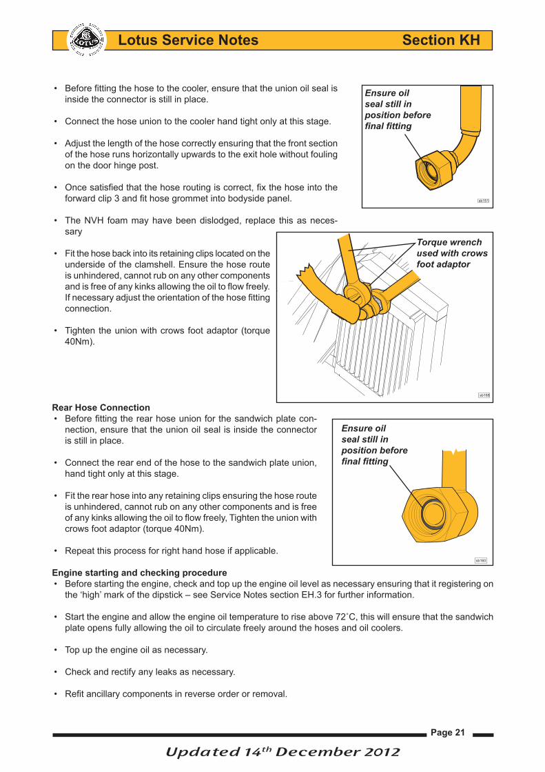
Before fitting the hose to the cooler, ensure that the union oil seal is •inside the connector is still in place.
Connect the hose union to the cooler hand tight only at this stage.•
Adjust the length of the hose correctly ensuring that the front section •of the hose runs horizontally upwards to the exit hole without fouling on the door hinge post.
Once satisfied that the hose routing is correct, fix the hose into the •forward clip 3 and fit hose grommet into bodyside panel.
The NVH foam may have been dislodged, replace this as neces-•sary
Fit the hose back into its retaining clips located on the •underside of the clamshell. Ensure the hose route is unhindered, cannot rub on any other components and is free of any kinks allowing the oil to flow freely. If necessary adjust the orientation of the hose fitting connection.
Tighten the union with crows foot adaptor (torque •40Nm).
Rear Hose ConnectionBefore fitting the rear hose union for the sandwich plate con-•nection, ensure that the union oil seal is inside the connector is still in place.
Connect the rear end of the hose to the sandwich plate union, •hand tight only at this stage.
Fit the rear hose into any retaining clips ensuring the hose route •is unhindered, cannot rub on any other components and is free of any kinks allowing the oil to flow freely, Tighten the union with crows foot adaptor (torque 40Nm).
Repeat this process for right hand hose if applicable. •
Engine starting and checking procedureBefore starting the engine, check and top up the engine oil level as necessary ensuring that it registering on •the ‘high’ mark of the dipstick – see Service Notes section EH.3 for further information.
Starttheengineandallowtheengineoiltemperaturetoriseabove72˚C,thiswillensurethatthesandwich•plate opens fully allowing the oil to circulate freely around the hoses and oil coolers.
Top up the engine oil as necessary.•
Check and rectify any leaks as necessary.•
Refit ancillary components in reverse order or removal.•
Ensure oilseal still in position beforefinal fitting
sb160
Torque wrench used with crows foot adaptor
sb168
sb151
Ensure oilseal still in position beforefinal fitting
Updated 14th December 2012

Page 22
Lotus Service Notes Section KH
Transfer Hose
RemovalRemove the front undershield - see Elise Service Notes 1. introduction section AA.2 for information.
Remove the front clamshell - see Elise Service Notes section 2. BR.6 for information.
Galvanic corrosion may occur between the oil hoses steel 3. union nuts at their connection to the aluminium threads of the front mounted coolers, it is essential to apply a liberal quantity of a suitable release agent around the area of the cooler unions before attempting to release them.
Disconnect the oil cooler transfer hose union connections 4. from the LH and RH coolers. Lower the hose and allow the oil to drain from both the hose and cooler into a suitable container(s), plug cooler ports to minimize oil loss.
IMPORTANT: It is essential that the ‘flats’ on the base of the oil cooler union threaded connection are held using an open ended spanner whilst loosening the hose union nut. Failing to follow this procedure may result in damage to the oil cooler.
Remove hose from either its 'P' clips retaining it to the front of the crash structure or if secured with cable 5. ties, cut the ties securing hose to the underside of crash structure and remove the hose from the vehicle.
RefitmentRenew any of the cable tie bases (if fitted) that have been •pulled away from the underside of the crash structure during the hose removal.
Clean and inspect the oil cooler union threads as neces-•sary in preparation to receive the new transfer hose.
Remove any plugs temporarily fitted to the oil cooler •ports.
Fit the new hose to the oil cooler union connections, •securing finger tight only (this will allow the cooler ends to turn within the connections whilst the hose is being routed into its correct position).
Either route the hose along the front of the crash structure and refit •into its 'P' cliles or route the hose along the L/H and R/H front edges of the crash structure, shaping it so that a bend is formed to match the position of the 3 cable tie bases.
Ensure the hose route is unhindered, cannot rub on any other com-•ponents and is free of any kinks allowing the oil to flow freely.
Tighten the oil cooler hose connections, to avoid placing unneces-•sary strain and movement on the oil coolers, hold the ‘flats’ on the base of the oil cooler unions threaded connection with an open ended spanner whilst using another spanner or crows foot adaptor on the hose connector unions, tightening connections to 40Nm.
LH oilcooler
Transferhose unionnut
Oil cooler ‘flat’ heldwith spanner
sb149
sb168
Torque wrench used with crows foot adaptor
sb147
Central crushtube
Tie bases & cable ties
Updated 14th December 2012

Page 23
Lotus Service Notes Section KH
Re-check alignment of the hose ensuring that it is not kinked or twisted.•
Model Year Update Information
The transfer hose cooler connections were altered from 45° to 90° angle to accommodate their fitment in the revised interior profile of the ‘11MY Elise clamshell. (This new hose was also carried over to the Exige).
Older level hoses are no longer available, and the latest level hose will not fit correctly in the existing ‘P’ clip mounts as used on pre-‘11MY vehicles, but will require the addition of cable tie fixings to secure it along the underside of the front crash structure.
If you replace a transfer hose on a vehicle originally fitted with an earlier level hose with the 45° angled con-nections then also order the additional cable ties and tie bases required to secure it to the base of the crash structure.
If the vehicle was only fitted with a single LH oil cooler then it will also be necessary to renew the RH oil cooler bracket at the same time as the modified hose as its dimensions and union connection angles were also changed to accommodate the modified transfer hose connections for ‘11MY vehicles.
Please see Technical Service Bulletin TSB 2011/12 for additional information.
Engine starting and checking procedureBefore starting the engine, check and top up the engine oil level as necessary ensuring that it registering on •the ‘high’ mark of the dipstick – see Service Notes section EH.3 for further information.
Starttheengineandallowtheengineoiltemperaturetoriseabove72˚C,thiswillensurethatthesandwich•plate opens fully allowing the oil to circulate freely around the hoses and oil coolers.
Top up the engine oil as necessary.•
‘C’ level cooler replacement bracket required for single cool-er application if ‘E’ level hose is replacing earlier level hose with 45°degree connections
Earlier level transfer hose with 45°degree connections
‘11MY level transfer hose routing under crash structure
Tie basesCable ties
‘11MY level transfer hose with 90°degree connections
sb147
Updated 14th December 2012

Page 24
Lotus Service Notes Section KH
Check and rectify any leaks as necessary.•
Refit ancillary components in reverse order or removal.•
LH Oil Cooler
Removal (RH Similar) Remove the front undershield - see Elise Service Notes introduction section AA.2 for information.1.
Remove the front clamshell - see Elise Service Notes section BR.6 for information.2.
Galvanic corrosion may occur between the oil hoses steel union nuts at their connection to the aluminium 3. threads of the front mounted coolers, it is essential to apply a liberal quantity of a suitable release agent around the area the cooler unions before attempting to release them.
Disconnect the transfer and bodyside hoses from the LH cooler. Lower the hoses and allow the oil from both 4. hoses and cooler to drain into a suitable container, plug cooler hose ports to minimize oil loss.
IMPORTANT: It is essential that the ‘flats’ on the base of the oil cooler union threaded connection are held using an open ended spanner whilst loosening the hose union nut. Failing to follow this procedure may result in damage to the oil cooler.
Release the M8 nyloc nuts and washers (2) securing the 5. oil cooler to its mounting bracket securing it to the crash structure.
The cooler can now be withdrawn forward from its housing 6. within the radiator housing and removed from the vehicle.
RefitmentIs the reversal of removal except:
Torque oil cooler to mounting bracket nuts to 22Nm.•
Fit the transfer and bodyside hoses to the oil cooler union •connections, securing finger tight only (this will allow the cooler ends to turn within the connections whilst the hose is being routed into its correct position).
Ensure the hose routes are unhindered, cannot rub on any other components and is free of any kinks allow-•ing the oil to flow freely. If necessary adjust the orientation of the hose fitting connection.
Tighten the both hose unions with crows foot adaptor (torque 40Nm).•
Engine starting and checking procedureBefore starting the engine, check and top up the engine oil level as necessary ensuring that it registering on •the ‘high’ mark of the dipstick – see Service Notes section EH.3 for further information.
Starttheengineandallowtheengineoiltemperaturetoriseabove72˚C,thiswillensurethatthesandwich•plate opens fully allowing the oil to circulate freely around the hoses and oil coolers.
Top up the engine oil as necessary.•
Check and rectify any leaks as necessary.•
Refit ancillary components in reverse order or removal.•
e280
Mountingbracket
Oil cooler
Radiatorshroud
Mountingnuts
Radiatorhose
Oil line hose connector
Updated 14th December 2012

Page 25
Lotus Service Notes Section KH
2ZR-FE Powertrain Engine Oil Cooling
Additional engine oil cooling is provided with the fitment of a single front mounted oil/air cooler radiator which is positioned to the right hand side of the engine cooling radiator ahead of the right hand front road wheel. This means that the total engine oil capacity is 7.2 litres to include the additional 2.4 litres required for the front mounted oil cooler as well as the feed and return lines.
Oil is fed to the oil cooler and returned to the engine via a Lotus developed oil filter housing incorporating oil line adapters and a thermostat assembly.
The Lotus designed oil filter/thermostat housing assembly ensures that cold oil bypasses the oil cooler circuit, butoncetheengineoiltemperaturereachesapproximately72˚thethermostatwillclosethebypassanddiverthot engine oil to flow around the oil cooler circuit.
Please note: Due to the fitment of a Lotus designed oil filter housing, if an engine replacement becomes nec-essary, the housing fitted to a 2ZR-FE service replacement engine must be discarded and replaced with the Lotus modified housing assembly.
The cooler system is contained to the right hand side of the vehicle.
The circuit consists of feed and return hoses fitted to the engine oil cooler filter housing at the rear of the vehicle as well as the front mounted oil cooler, these are connected to their respective feed and return pipes positioned between LH bodyside panel and chassis - see illustrations on next page for additional information.
Oil filter housing/thermostat assembly.
Front mountedoil cooler
Front oil coolerfeed hose
Front oil coolerreturn hose
Oil coolerreturn pipe
Oil coolerfeed pipe
Oil coolerfeed hose
Oil coolerreturn hose
e277
Updated 14th December 2012

Page 26
Lotus Service Notes Section KH
Oil filterhousing
Feedhose
Bodysidesill panel
Return hose
Connectors to sill pipes(torque 40Nm)
e279
Oil coolerfeed hose
Oil coolerreturn hose
bodysidecooler pipes
Oilcooler
Radiatorhose
Crashstructure
Radiatorshroud
Connectorsto pipes(torque 40Nm)
Connectorsto oil cooler (torque 40Nm)
e278
Updated 14th December 2012