low energy cooling in multi-storey buildings for hot, …
TRANSCRIPT

LOW ENERGY COOLING IN MULTI-STOREY BUILDINGSFOR HOT, ARID CLIMATES
byAMIRA M. MOSTAFA
B.Arch. Cairo University1984
SUBMTITED TO THE DEPARTMENT OF ARCHITECTURE IN PARTIAL FULFILLMENT OF THE REQUIREMENTSFOR THE DEGREE OF
MASTER OF SCIENCE IN ARCHITECTURE STUDIESAT THE MASSACHUSETTS INSTITUTE OF TECHNOLOGY
JUNE 1989
@ 1989 Amira M. Mostafa. All rights reserved.
The author hereby grants to MIT permission to reproduce and to distribute publiclycopies of this thesis document in whole or in part
Signature of AuthorAmira M. Mostafa
Department of Architecture: May 9, 1989
Certified by
Principal Research Associate of Building
Accepted by9~ASSAC!iUSEFT8 iMSTITU
MASSVXHUSEM INSNOF TECHN4O!OGY
JUN 0' 198
tWAMW
7Ti'mohy JohnsonTechnology: Thesis Supervisor
an BeinartE Chairman: Departmental Co1 'ttee for Graduate Students
Rotch

'77 7 77 I7
ii
LOW ENERGY COOLING IN MULTI-STOREY BUILDINGSFOR HOT, ARID CLIMATES
LOW ENERGY COOLING IN MULTI-STOREY BUILDINGSFOR HOT, ARID CLIMATES
byAMIRA M. MOSTAFA
Submitted to the Department of Architecture on May 9th, 1989 in Partial Fulfillment of the Requirements for the Degree ofMasters of Science in Architecture Studies
ABSTRACT
This thesis discusses passive and low energy cooling strategies and systems in hot arid climates. The choice of a certainstrategy, as well as determining the appropriate cooling schemes for such a context becomes of prime importance in developingthe optimum energy conscious building design.
The motivation for working in this area of research stems for the need facing architects to start developing a serious sense forenergy considerations in their architectural design, especially in existing and multi-storey buildings.
Here, in this research, the different factors that govern the control of heat gain through the envelope of the building will beanalyzed. Also, solutions to minimize the cooling load for dwellings will be suggested/provided; by means of selecting theadequate cooling systems (evaporative, convective, and radiative) that promote the optimum desired thermal comfort.
This research concludes its technical analysis with an architectural design for two schemes; The first is a cooling system thatcan be applied to new buildings, or retrofitted to existing ones. It uses evaporative coolers and solar chimney systems at day-time. It also uses night-time forced ventilation to cool the ordinary slab. The second can be applied in new buildings. It usesevaporative coolers and solar chimney systems at day-time. It also uses night-time forced ventilation through cored slabs.This design, and these schemes, are perceived as a starting point for further development and more research.
Thesis Advisor: Prof. Timothy JohnsonTide: Principal Research Associate of Architecture
iii

To my love, best friend, husband, and father of my Mariam and Muhammad... Yasser El-Quessny.The one who taught me to live and think Art and Architecture.If it wasn't for his support, love, help, encouragement I would not have reached this state of accomplishment.
iv
ACKNOWLEDGEMENT
With all the respect and gratitude, I would like to thank my supervisor Timothy Johnson; whom through his guidance,encouragement, and expertise I learned a lot about the research subject and methodology, as well as about myself. I am proud tobe one of his students.I would like also to express my gratitude to Prof. Leon Glicksman, Prof.Eric Dluhosch, Prof. Harvey Bryan, and ReinhardGoethert for their valuable comments on my work.
To my friends who made my stay in the States rather pleasant.To Yasser for his hard work on editing this thesis.To Ayman , Ahmed, and Adil for their invaluable help.
And last but not least to my teachers at Cairo University "Architecture Department " for their encouragement andrecommendations .
V

Table of Contents
ABSTRACTPREFACE xi
CHAPTER.1. EXAMPLES OF PASSIVE AND LOW ENERGY SOLAR DESIGN 1A. Historical Responses to Cooling Needs 1B. Passive and Low Energy Cooling (recent solutions) 4
B.1. Bateson Building 4B.2. Princeton Professional Park 8B.3. Office Block in the Egyptian Sahara 9
CHAPTER.2. STRATEGIES FOR SUPPLEMENTING PASSIVE/LOW ENERGYA. Heat Gain in Buildings 11
A. 1. Heat Gain from Building Envelope 11A.1.1. Windows 12A. 1.2. Solar Control and Shading Devices for Windows 13
A.2. Heat Gain from Ventilation and Infiltration Loads 13A.3. Heat Gain from Electric Lighting 13A.4. Internal Heat Gain from Building Occupants 14
B. Thermal Comfort for People inside their Dwellings 15C. Cooling Strategies 19
C. 1. Evaporative Cooling 19C. 1.1. Direct Evaporative Coolers 19C. 1.2. Indirect Evaporative Coolers 24C. 1.3. Two-stage Evaporative Coolers 27
C.2. High Mass Cooling with Night Ventilation 28C.3. Natural Ventilation (promoting air movement within the building) 32
C.3. 1. Motive Force Caused by Wind Blowing onto the Facade 32C.3.2. Thermal Motive Force 32
vi

CHAPTER.3. APPLICATION OF COOLING SYSTEMSA. Cooling Load Calculations
A. 1. Definitions and Symbols (of terminology used in this chapter)A.2. Overall Coefficient of Heat Transmission for Roofs and walls ,and peak heat gain for roofs
A.2. 1. Overall Coefficient of Heat Transmission for Existing RoofA.2.2. Overall Coefficient of Heat Transmission for Redesigned RoofA.2.3. Peak Heat Gain for Existing BuildingA.2.4. Peak Heat Gain after Redesigning the BuildingA.2.5. Overall Coefficient of Heat Transmission for Walls
A.3. Heat Gain through GlassA.3. 1. Peak Heat Gain through Glass by Solar Radiation in Existing BuildingA.3.2. Peak Heat Gain through Glass By Solar Radiation after Redesigning the Building
A.4. Peak Sensible Heat Gain from PeopleA.5. Peak Heat Gain from Internal LightA.6. Summary Of Peak Heat Gain
B. Selecting Cooling SystemsC. Cooling Systems and Schemes
C. 1. Scheme OneC. 1.1. Using High Mass Cooling with Night VentilationC.1.2. Supplementary CoolingC.1.3. Forced Night Ventilation of Thermal Mass
C.2. Scheme TwoC.2. 1. Night-time Forced VentilationC.2.2. Day-time Use of Evaporative CoolersC.2.3. Sizing the Evaporative Cooler
C.2.3. 1. Using Two-stage Evaporative CoolingC.2.3.2. Using Indirect Evaporative Cooler Only
C.2.4. Stack-effect Ventilation by Means of the Solar ChimneyC.2.4. 1. Design Decisions with Respect to Building Materials of the Solar ChimneyC.2.4.2. Velocity of Air inside the Duct due to the Stack-effectC.2.4.3. The Duct Size of the Solar ChimneyC.2.4.4. Volume of Air Flow into the Solar Chimney (for one apartment)C.3. Scheme ThreeC.4. Scheme Four
C.4. 1. Designing Decisions with Respect to Building Materials of the Solar ChimneyC.4. 1. Velocity of Air inside the DuctC.4.3. The Duct Size of the Solar ChimneyC.4.3. Volume of Air Flow into the Solar Chimney (for one apartment)
35353737384142424545464848495051515454555656575959606363656566686969696970
vii
C.5. Summary for Designing the System 70C.5. 1. Solar Chimney (Scheme Two) 70C.5.2. Evaporative Cooler (Scheme Two) 71C.5.3. Solar Chimney (Scheme Four)
C.6. Evaluation of the Four Cooling Scheme 72
CHAPTER.4. DESIGN SYNTHESIS 73
APPENDICESAppendix .A. 107Appendix .B. 111Appendix .C. 115Appendix .D. 116Appendix .E. 117Appendix .F. 118
BIBLIOGRAPHY 122
viii

List of Figures
Index Title/Description Page
Fig. 1. Pharaonic House of Neb-Amun 1Fig.2. House of Muhibb Al-din Muwaggi (Cairo/Egypt) 2Fig.3a. The Bateson Summer Operation 5Fig.3b. The Bateson Central Atrium 6Fig.4. The Bateson Building's Heating and Cooling devices 7Fig.5. Princeton Professional Park 9Fig.6. Office Block in Egypt 10Fig.7. Bioclimatic chart(s) 15Fig.8. Bioclimatic and Cooling Strategies 16Fig.9. Plotting monthly maximum and minimum DBT and RH for Alexandria/Egypt 18Fig.1Oa. Evaporative Cooling Tower with wetted baffles 20Fig. 10b. Details of Cooling Systems (designed by Hassan Fathy) 21Fig. 11. Direct Evaporative Cooler 22Fig. 12. Indirect Evaporative Cooling Process 24Fig. 13a. Schematic Design of dry surface evaporative Cooler 25Fig. 13b. Schematic Design of dry surface evaporative Cooler 26Fig. 14. Two-stage Evaporative Cooler 27Fig. 15. Solar Chimney system (developed by R. Haisley) 33Fig. 16. Details of Existing Roof 37Fig. 17. Details of Redesigned Roof 38Fig. 18. Alternative Wall Design(s), and the selected one(s) 42Fig. 19a. South-east and north-west orientations of windows (showing shading devices) 46Fig. 19b. South and south-west orientations (showing shading devices) 47Fig.19c. West and east orientations (showing shading devices) 47Fig.20. Plotting Cairo's Summer time design conditions on the Bioclimatic chart
(in order to determine the cooling system to be used) 50Fig.21. Schematic Design of the Cooling Schemes 52Fig.22. Dimensions of Proposed Cored Slab 53Fig.23. Plotting Two-stage Evaporative Cooling Process on Psychrometric Chart 58Fig.24. Plotting Indirect Evaporative Cooling Process on Psychrometric Chart 62Fig.25. Scheme Four 76Fig.26. Day-time Operation 77Fig.27. Night-time Operation 78
ix

Fig.28. Cored Concrete Slab (as one of the cooling devices) 80Fig.29. Section Through External Wall (showing operation of its openings) 81Fig.30a. Window Design 82Fig.30b. Optional Position of Window's Shading Device 83Fig.3 1. Diagrams of Two-stage Evaporative Cooler 85Fig.32. Air to Air Heat Exchangers 86Fig.33. Water to Air Heat Exchangers 87Fig.34. Schematic Design of the Cooling Tower (using air-to-water heat exchanger) 89Fig.35a. Schematic design of the Cooling tower (using Air-to-air heat exchanger) 90Fig.35b. Side-view of Cooling Tower 90Fig.36. Natural Air Movement Using Chimney 92Fig.37. Operation of the Cooling Scheme 93Fig.38. Original Plan of the Selected Multi-storey Building 94Fig.39. Plan Alternative Design after Applying SAR Method 95Fig.40. Selected Plan Alternative 96Fig.41. The Roof Layout 97Fig.42. Schematics Showing Atrium Solar Chimney 98Fig.43a. Elevation of Scheme Four 99Fig.43b. Sky-line of Scheme Four 100Fig.44a. Day-time Operation 102Fig.44b. Retrofitting the Original Plan and Positioning the Cooling System 103Fig.45. Skyline of Scheme Two 104Fig.46. Solar Intensity on Vertical and Horizontal Surfaces of Cairo/EGYPT 116
Table. 1. Summary of Cooling Loads using CLTD and CLF methods 39Table.2. Engineering Weather Data for Cairo/EGYPT 118Table.3. Climatic Weather Data for Cairo/EGYPT 119Table.4. Daily Total Solar Radiation Received on Surfaces of Various Orientations 121
x

PREFACE
For the last two decades, much research has been done in the area of energy conscious building design in various climatic
contexts. Surprisingly, though, most of its application is directed towards either building new buildings, and hence, we don't
rectify the mistakes done to the preceded models, or enhance and improve on low rise, existing and new.
In this research, technical information shall be crystallized into a comprehensive coherent building model. I chose to take
my model in Cairo/Egypt, and apply it to an existing multi-story residential building.
Egypt has a variegated climate, however, the prevailing zone in which most of the urban fringe falls is in the hot-arid zone.
It also has a housing problem. This problem could be expressed not only in terms of units shortage, but also in terms of
quality of the existing units and how they respond to the universal energy concerns, and by expansion, the problem of
designers' tendency to ignore energy concerns.
This thesis addresses the question of energy conscious building designs in a multi-disciplinary fashion. It discusses passive
and low energy cooling strategies and systems in context of other pilot projects that have been done elsewhere. The problems
and opportunities that arise in each aspect of cooling and comfort problem in the building design and the operational processes
are also examined. The reader of this thesis will be able to understand means of providing thermal comfort other than strict
temperature control; means to reduce heat gain to the building in order to reduce cooling system loads; means of using
ventilation and air movement as a substitute for, and/or a supplement to, selected cooling systems. The choice of a certain
strategy, as well as determining the appropriate cooling system for a given context becomes of prime importance as it is
explained in chapters two and three.
This thesis takes an unorthodox approach to conclude the research work. It could have recommended some strategies for
application, or state some design guide lines for future research and applications; Instead, it tries to put the research
hypothesis to the direct ultimate test by designing a building. I chose to test my ideas for an urban common, middle-class,
multi-storey residential building in the hot arid climatic context of Cairo / Egypt.
xi

Nevertheless, I cannot claim that my hypothesis is correct, but certainly hope that such synthesis of ideas and design
thinking efforts could pave the way to further development and enhancement to the chosen model and similar encountered
models in any given context.
This thesis is comprised of:
Chapter-I reviews some of the recent architectural and technical examples that helped pave the way for perceiving energy
conscious designs. In each of the illustrated examples, I shall be discussing the design's major technical strategies chosen for
it, together with the implementation's pros.
Chapter-2 explores the various strategies for supplementing passive and low energy systems, using two-stage evaporative
coolers, natural ventilation (achieved by the stack-effect and the solar chimney), and the cooling effect of night ventilation of
the thermal mass (we use this mass to radiate its coolth to the interior of the dwelling). Also the mechanisms for heat gain and
comfort determination are reviewed in order to arrive to an optimum solution/strategy. This theory is applied analytically in
chapter.3 to generate the recommended schemes.
In Chapter-3, application of cooling systems is discussed in context of a multi-storey residential building in Cairo/Egypt.
Schemes for cooling systems are also discussed in terms of: Peak heat gain per hour in the building (which is reduced by
45% after redesigning some elements of the building's envelope), and application of four different cooling schemes (each
combines different cooling systems, to the selected multi-storey model).
Two optimum schemes are then chosen for architectural considerations and their architectural elements are sized so that they
will be active parts of a comprehensive cooling scheme (ex: evaporative cooling tower and solar-atrium chimney).
Chapter-4 concludes the analysis, ideas, strategies and schemes. Two comprehensive architectural solution are presented;
serving as an introduction for other research work and design efforts.
xii
CHAPTER ONE
EXAMPLES OF PASSIVE AND LOW ENERGY SOLAR DESIGN
A
HISTORICAL RESPONSES TO COOLING NEEDS
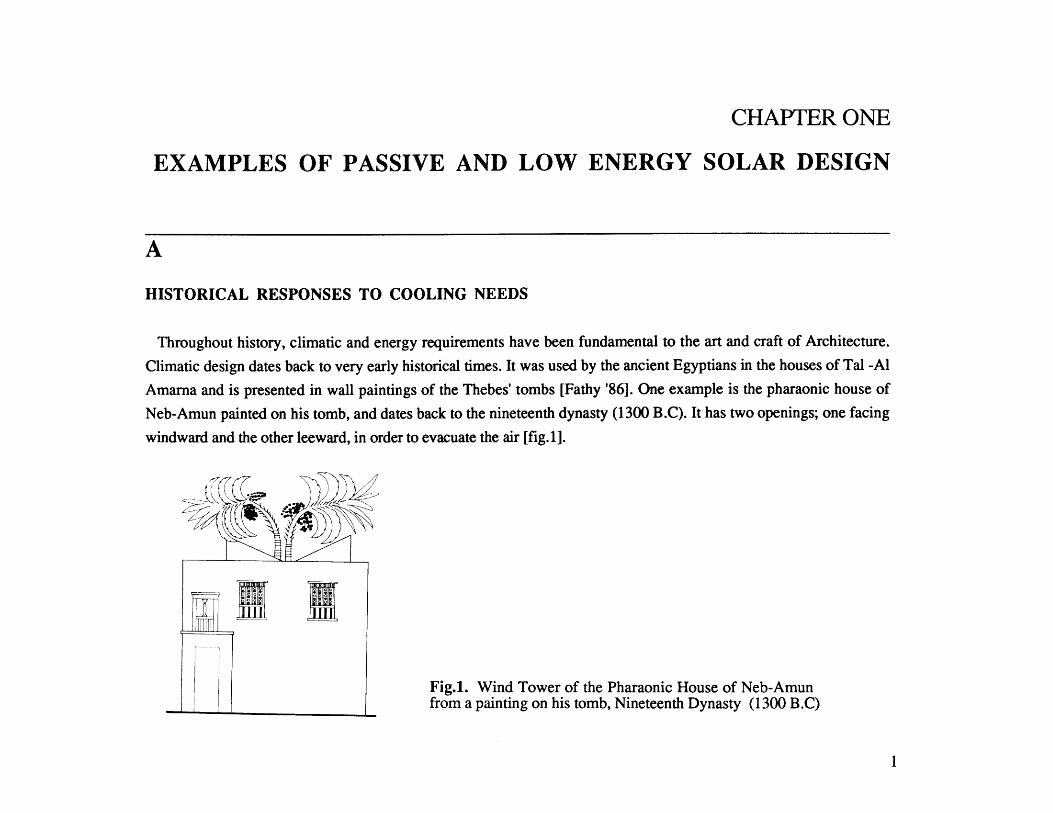
Throughout history, climatic and energy requirements have been fundamental to the art and craft of Architecture.
Climatic design dates back to very early historical times. It was used by the ancient Egyptians in the houses of Tal -Al
Amarna and is presented in wall paintings of the Thebes' tombs [Fathy '86]. One example is the pharaonic house of
Neb-Amun painted on his tomb, and dates back to the nineteenth dynasty (1300 B.C). It has two openings; one facing
windward and the other leeward, in order to evacuate the air [fig.1].
Fig.1. Wind Tower of the Pharaonic House of Neb-Amunfrom a painting on his tomb, Nineteenth Dynasty (1300 B.C)
I

Traditional and vernacular buildings, at their best, are direct expressions of adaptations to the climate. The human
shelter, prior to the Industrial Revolution, has always reflected a rational understanding of the sun's solar power,
generosity, as well as cruelty. It has also been perceived as an art when it comes to the building design and orientation.
Centuries ago, primitive people learned, by trial and error, the influence of solar energy on the design of their
dwellings. In hot arid regions, for example, the characteristic problem is high day time temperatures, as well as fairly
low temperatures during night times. There are numerous architectural examples that used natural forces in these regions
(hot arid) that can be found in Egypt, Turkey, Iran, Iraq. Shown in fig.2 is the house of Muhibb Al-Din Muwaggi in
Cairo /Egypt [Steele '88].
Fig.2. House of Muhibb Al-Din Muwaggi Air Movement Study
2
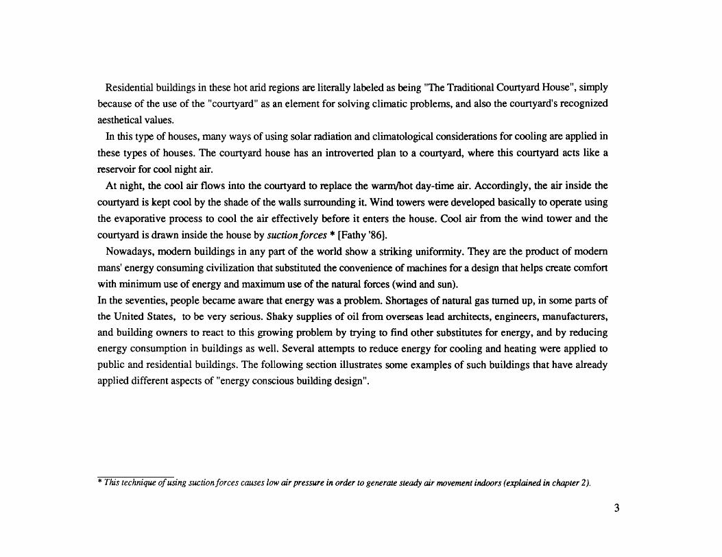
Residential buildings in these hot arid regions are literally labeled as being "The Traditional Courtyard House", simply
because of the use of the "courtyard" as an element for solving climatic problems, and also the courtyard's recognized
aesthetical values.
In this type of houses, many ways of using solar radiation and climatological considerations for cooling are applied in
these types of houses. The courtyard house has an introverted plan to a courtyard, where this courtyard acts like a
reservoir for cool night air.
At night, the cool air flows into the courtyard to replace the warm/hot day-time air. Accordingly, the air inside the
courtyard is kept cool by the shade of the walls surrounding it. Wind towers were developed basically to operate using
the evaporative process to cool the air effectively before it enters the house. Cool air from the wind tower and the
courtyard is drawn inside the house by suctionforces * [Fathy '86].
Nowadays, modem buildings in any part of the world show a striking uniformity. They are the product of modem
mans' energy consuming civilization that substituted the convenience of machines for a design that helps create comfort
with minimum use of energy and maximum use of the natural forces (wind and sun).
In the seventies, people became aware that energy was a problem. Shortages of natural gas turned up, in some parts of
the United States, to be very serious. Shaky supplies of oil from overseas lead architects, engineers, manufacturers,
and building owners to react to this growing problem by trying to find other substitutes for energy, and by reducing
energy consumption in buildings as well. Several attempts to reduce energy for cooling and heating were applied to
public and residential buildings. The following section illustrates some examples of such buildings that have already
applied different aspects of "energy conscious building design".
* This technique of using suctionforces causes low air pressure in order to generate steady air movement indoors (explained in chapter 2).
3
B
PASSIVE AND LOW ENERGY COOLING (RECENT SOLUTIONS)
Storage of Heat and Coolth
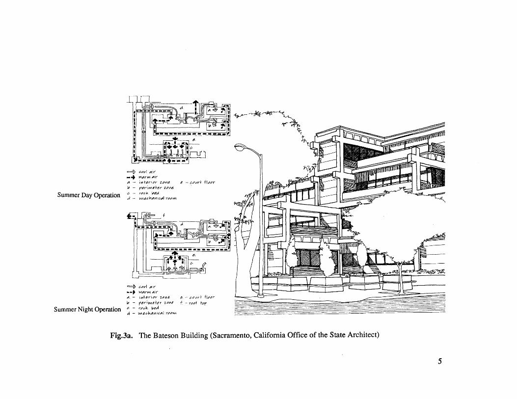
B.1. Bateson BuildingThe Bateson building is a four-story office building in Sacramento California [Brown '85]. This building was
designed by Peter Calthorpe during the time when Sim Van der Ryn (Berkeley professor of Architecture, known for his
work in solar energy), was appointed by the governor to work with the office staff on this pilot project. Sim Van der
Ryn assembled an "Energy Ethic Team" that comprised the staff team of the California State Architect's office together
with the architect. They developed a variety of approaches and solutions for the building's envelope and equipment
which made this building quite a distinguished one.
In this example mechanical ventilation was used to insure adequate night time air movement over the interior
mass, and thereby improve the building's cooling potential. Scheme for night ventilation of the thermal mass is
designed to absorb heat during the day into the mass of the building and give up this heat to the cool ventilating air
during the night. Because the rate of air movement is frequently low at night, its flow is often poorly distributed and the
amount of thermal mass area is limited, the cooling potentials in this passive systems were limited. Therefore by using
fans, the amount of heat removed during the night was increased significantly.
Mechanical night ventilation of the thermal mass in this building is an important cooling strategy. The cooling effect of
this night ventilation satisfies about 65% of the building's cooling load [Brown '89]. The building uses extensive
shading devices and its offices are lit by natural day light admitted by an interior atrium [figs. 3&4].
4
L4 -- e~ee
Sume Da prto8"-"
A - m imod room
.4 Yrm ir- w~er'or 2,00e -~~+ W~- el ee zoje ro o
Summer Dayh Operation6- Uk/8
Fig3a TheI Bat ulig(armntClfri fieofteSaeAciet
5

V /I Iw f~C'
jI
/
iz-
Fig.3b. The Bateson Building: Central Atrium6

VE91CAL 60L0VW O?D.IfGT SUw 0"T oF AMUN
NWei WW FOIL PAIV&
1o. MMO.uc
N W MI LeTW SVMTiA& 14 NMT9 OG41MV
,coolCRA AJ MsT9..
Cn 4UA110 THW e0ltJr1w 00MM To ruz+HKAT AXW V"Mcaru1? STV T mLr
V0 DA.
N. 10I1.1,DImffU"(ag*n cmkxrJL) MeLoMW ID Wa mL
saT armLwr ow
N IOF u0H11clf ''Q4 fwi
-MT WIrL WNar& W4 9Z OAMTb, 107 ffw WARG, MAUft& w Elfw.
-07e OF UM- CMM 1 A |e gqxm by"Ul4IGHT VfTING' THIG WKrn ClU4 A1T:G
~.AcroG 1W~icMco.. C0 lwrHT P-M 1V "Mar 0MW M memsWof 1 c0om1 MMF fTV mlt izo t 10rP. TE I* T QAY. -140 wcL0D LNW#L bATtow
mem to or 1e Amw CCouw Loo.
Fig.4. The Bateson Building Heating and Cooling Devices:Solar Collectors for Heating Water, Rock Bed, and Building Mass to Store Coolth
7
The night ventilating system works by pulling cold outside air down the ventilation shaft at night, and distributing it to
each space by HVAC systems. It then picks up heat from the structure and is exhausted to the outside. The major mass
area in this building is the ceiling, where the pre-cast concrete double-T's are left exposed.
The thermal mass of the building is supplemented with a rock-bed storage system. Rock beds increase the thermal
storage beyond what is available in the building structure. This implies enlarging the thermal mass of the building, and
accordingly, increasing its ability to store energy [McGuiness & Stein '86].
In the heating system, air is drawn by fans and ducts though a bed of rocks. Heat is then given off to the rocks, and
the air is recirculated to a location in the hot space to collect more heat. At night, when heat is needed, air is drawn from
the occupied space through the rock-bed, where it picks up heat and is distributed back to the occupied space. The fans
are required to charge and discharge the rock-bed frequently as part of the conventional HVAC system.
The size of the rock bed is a function of the input air temperature, heat storage requirements, rock sizes, and the air
flow rate [Jones '84]. Rock beds for cooling are similar to those for heating, except that the source of cool air is
frequently outside the building.
In climates that experience a large durinal temperature swing, cool outside air could be drawn through the bed at night.
In hot arid climates, the rocks may be cooled by evaporation.
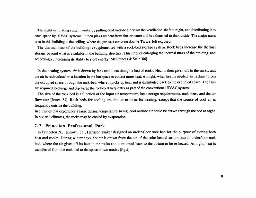
>.2. Princeton Professional ParkIn Princeton N.J. [Brown '85], Harrison Fraker designed an under-floor rock bed for the purpose of storing both
heat and coolth. During winter days, hot air is drawn from the top of the solar heated atrium into an underfloor rock
bed, where the air gives off its heat to the rocks and is returned back to the atrium to be re-heated. At night, heat is
transferred from the rock bed to the space in two modes [fig.5]:
8
Heating
Cooling
Fig.5. Princeton Professional Park
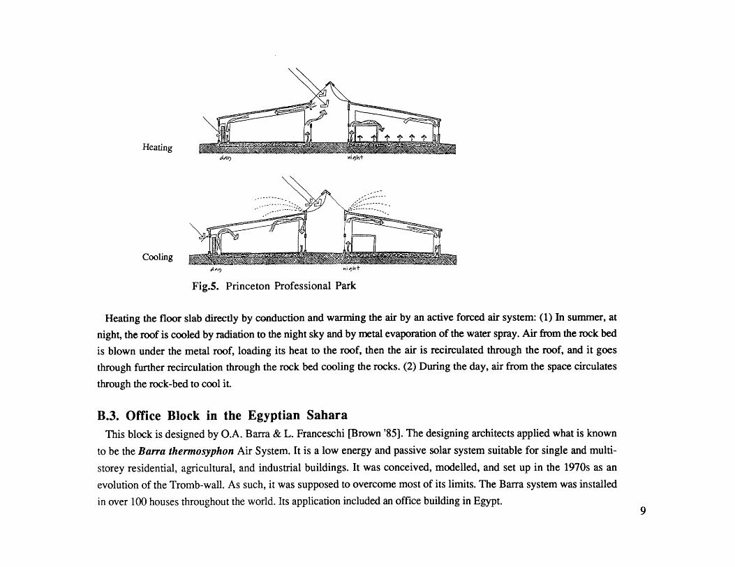
Heating the floor slab directly by conduction and warming the air by an active forced air system: (1) In summer, at
night, the roof is cooled by radiation to the night sky and by metal evaporation of the water spray. Air from the rock bed
is blown under the metal roof, loading its heat to the roof, then the air is recirculated through the roof, and it goes
through further recirculation through the rock bed cooling the rocks. (2) During the day, air from the space circulates
through the rock-bed to cool it.
B.3. Office Block in the Egyptian SaharaThis block is designed by O.A. Barra & L. Franceschi [Brown '85]. The designing architects applied what is known
to be the Barra thermosyphon Air System. It is a low energy and passive solar system suitable for single and multi-
storey residential, agricultural, and industrial buildings. It was conceived, modelled, and set up in the 1970s as an
evolution of the Tromb-wall. As such, it was supposed to overcome most of its limits. The Barra system was installed
in over 100 houses throughout the world. Its application included an office building in Egypt.9
a1; orbecr
e hnnels
c Wineynte D
a) Winter Day
c) summer Day
- b) Winter Night
d) Summer Night
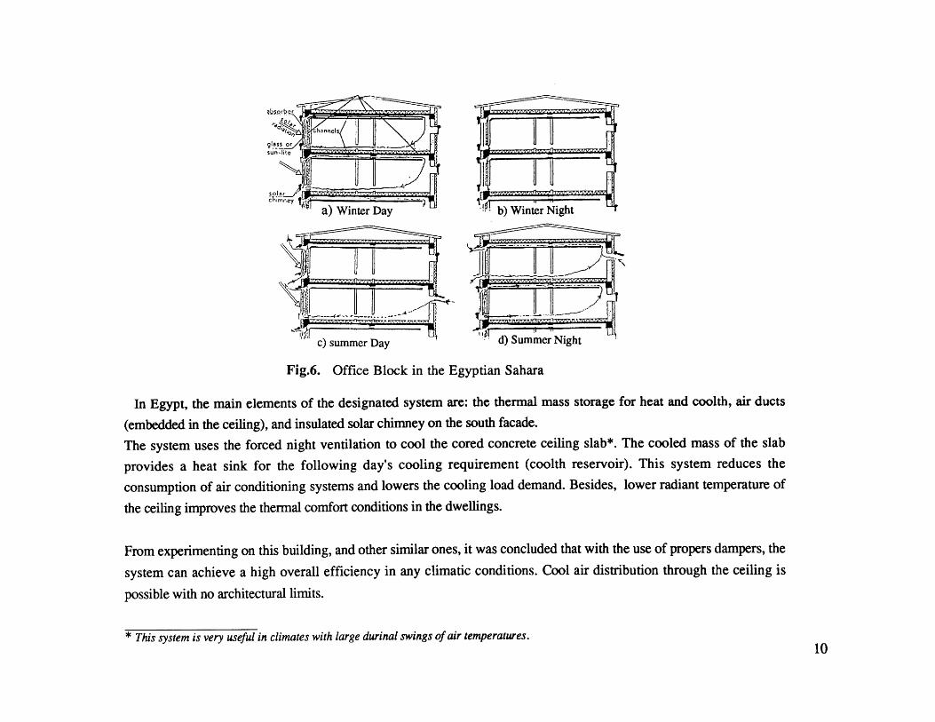
Fig.6. Office Block in the Egyptian Sahara
In Egypt, the main elements of the designated system are: the thermal mass storage for heat and coolth, air ducts
(embedded in the ceiling), and insulated solar chimney on the south facade.
The system uses the forced night ventilation to cool the cored concrete ceiling slab*. The cooled mass of the slab
provides a heat sink for the following day's cooling requirement (coolth reservoir). This system reduces the
consumption of air conditioning systems and lowers the cooling load demand. Besides, lower radiant temperature of
the ceiling improves the thermal comfort conditions in the dwellings.
From experimenting on this building, and other similar ones, it was concluded that with the use of propers dampers, the
system can achieve a high overall efficiency in any climatic conditions. Cool air distribution through the ceiling is
possible with no architectural limits.
* This system is very useful in climates with large durinal swings of air temperatures.10

CHAPTER TWO
STRATEGIES FOR SUPPLEMENTING PASSIVE/LOW ENERGY
A
HEAT GAIN IN BUILDINGS
Inside a building, energy is consumed for various functions to augment comfort and increase utility. Energy is used
for heating, cooling, lighting, providing power for equipment as well as heating for domestic hot water. The
classification by use is readily understood and useful for comparison purposes. However, there is also a somewhat
different classification that is equally useful in managing energy flows within buildings.This classification labels energy
consumed as loads* [Dubin '78]. Building loads are energy requirements for the environmental control of temperature,
humidity, and ventilation, as well as for the building's lighting energy inside the building envelope. The term building
load is used to specify energy (in Btu or Kilo-watt hour/kwh) that is required to maintain desired indoor space
conditions and to operate building equipment.
A.1. Heat Gain from the Building Envelope
The building envelope consists of walls, windows, doors, roofs, and floor surfaces. It is always subjected to varying
influences of climate on each of its orientations. The qualities of the building envelope directly influence the heating and
cooling peaks as well as the average requirements of the cooling loads.
*This classification is the framework on which the feasibility study of different cooling systems will follow later (in this chapter & the
appendix).11

The thermal properties of the envelope are determined by the combination of wall mass, thermal resistance, exterior
surface color and texture, and also the type and location of glazing. The effect of each property depends upon the mode
of operation of the heating and cooling systems. The building wall must retard heat flow in and out (ex: Massive Walls).
On exterior surfaces, however, light colors decrease solar heat gain, whereas dark colors increase solar heat gain. Also,
wall textures or vines can shade and maintain a still-air film on building surfaces to reduce heat loss and heat gain.
Windows have a major effect on buildings' cooling and heating loads. These loads are generally affected by the solar
radiation transmission through the glass, solar heat gain by conduction, and the window's air infiltration. Heat
transmission is much greater through glass than through most opaque walls. However, the overall coefficient of heat
transmission (U values) for walls can be reduced to 0.04 or less, where single glass has a U value of about 1.15,
double glass of 0.55 to 0.69, and triple glass of 0.35 to 0.47.
A.1.1. WindowsPerhaps of all the building envelope's elements, windows are perceived to be the main element that governs the
envelope's configuration. They are frequently provided in gross excess of any requirement for natural light, ventilation,
or view. Large glass areas can cause discomfort for persons who must sit in front of them, because of the sun's heat and
radiation. On the other hand, the elimination of all windows could exclude natural light and vision, and could also create
somewhat incompletely understood psychological problems, even though windowless buildings would reduce the
problem of solar heat gain in summer, air infiltration, and heat loss. The percentage of window to opaque wall can be
reduced if the window shape, placement in the wall, type of glazing, and use of shading devices are designed with an
awareness of their combined impact on energy consumption and user needs. The shape of window (the tilting angle of
the glass, and the window's orientation) can be important, even where the window's area remains constant, due to the
effect of its shape on the amount of solar radiation transmitted through the glass.
12
A.1.2. Solar Control and Shading Devices for Windows
The use of shading devices to reduce heat gain in the summer is most effective when located on the exterior of the
building, and is particularly effective when the shading device can be moved to respond to the changing sun elevations.
Fixed solar fins and overhangs eliminate direct solar penetration in the summer time. Nevertheless, they also block out
some of the solar rays in the late spring and early fall, when rays could be useful for heating. Solar control is most
effective when designed specifically for each facade, since time and duration of solar radiation vary with the sun's
altitude and azimuth.
A.2. Heat Gain from Ventilation and Infiltration Loads
Operable windows permit the use of natural ventilation, but unless they are properly equipped with weather stripping
and tight locking devices, these same windows may increase infiltration loads. Ventilation is delightful when outdoor
conditions are such that the air is clean enough, pure enough, and dry enough to be enjoyed. However, natural
ventilation cannot penetrate deeply into a building that is not cross ventilated [Dubin '78]. Building plans should respond
in such a way so as to allow adequate ventilation needed. The number of hours in a year in which natural ventilation can
be effectively used must be analyzed to reduce the possible increased infiltration, heat loss, and heat gain, when natural
ventilation is not useful.
A.3. Heat Gain from Electric Lighting (and its contribution to the building's heating andcooling loads requirements)
Electric Lighting contributes heat to occupied spaces as an inevitable by-product of its function (illumination). And
unless special heat removal techniques are used, all of the electric power fed into the lights, eventually, generates heat in
the occupied space.
The amount of heat generated from lights is a function of the illumination level and the efficiency of the light source.
Day light can substitute for artificial lighting when windows and rooms are properly proportioned and finished.13

A.4. Internal Heat Gain from Building Occupants (and their Contribution to the building'sheating and cooling loads requirements)
The metabolic energy of people can contribute substantially to the amount of heat generated in the building. This heat
may increase the cooling requirement in a hot climate or in a building that has a cooling load due to other internal sources
of heat gain. It may also decrease the heating requirements of a building in a cool climate.
The total sensible heat gain from people in Btu*, is found by multiplying the average number of occupants in the
building by the rate of heat gain per person.
*The amount of heat and moisture generated by people is a function of age, sex, activity, etc. Most passive cooling systems cannot remove
water vapor from the air; therefore, only the sensible heat gains (which raise the air temperature) are considered in determining the internal heat
gains from occupants. However, conventional mechanical refrigeration systems that remove moisture from the air in the cooling process,
require additional energy to condense the water vapor and to prevent an uncomfortable increase in humidity in the lower temperatures. This
additional load on the cooling system is called latent heat, and should be added to the sensible heat gain to determine the total gain for
systems that remove water vapor in addition to cooling the air.
14

B
THERMAL COMFORT FOR PEOPLE INSIDE THEIRDWELLINGS
The Bioclimatic chart [fig.7] shows the relationship of the four major climatic variables that determine human comfort.
By plotting temperature and relative humidity values, we can determine whether the resulting conditions are comfortable
or not, and accordingly, proceed for a design strategy [Brown '78].
IL.
C'
N a ;A for M01
JkAiAIE Ilkrf
I7 ,.' I*/Ievi.
~$I4tV& HumJ.t~*40'/. q56'4 0O~ 61OY. 7 4o~
Fig.7a. Bioclimatic ChartShowing Relation Between Relative Humidity, Dry Bulb Temperature
Fig.7b.Showing
Bioclimatic ChartComfort Zone and Shading Line and Wind Line
15

PASSIVE / LOW ENERGY SOLAR STRATEGIESLow energy and/or passive solar strategies for attaining Thermal Comfort can be determined by the Bioclimatic Chart:
The Bioclimatic chart is subdivided into zones that define heating and cooling strategies. The zones crossed by the lines
plotted indicate the strategies that may be appropriate for a particular climate [fig.8].
07,~~~~ rer% IVr ey 07 , r o0 20 '% 7
Relat hve- HuvvAIoit
Fig.8. Bioclimatic chart with Design Strategies.16
In most climates, there is a seasonal change from one strategy to another. Furthermore, some months may have several
different strategies, but in most cases the designer should select a few strategies that are compatible with each other and
with other design issues, and that is for economical reasons.
Passive solar heating is usually an appropriate strategy for months when the plotted lines fall below the comfort zone.
The passive solar heating zone is based on clear day radiation values and certain assumptions about glazing areas and
insulation levels. The zone may be extended to lower temperatures, depending on the building design, radiation levels,
and the desired percentage of the annual heating load to be supplied by solar energy.
There are four cooling strategies represented by four, somewhat, overlapping zones above the comfort zone. These
are: Natural ventilation, which depends solely on air movement to cool occupants; Large thermal mass, which depends
on the building's materials to store heat during the night and re-radiate it at day; Large thermal mass (combined with
night ventilation), which relies on mass-heat storage during the day and ventilation at night to cool the mass; Evaporative
cooling, which lowers the indoor air temperature by evaporating water in the space.
All of these strategies fall into one of three general categories: open, closed, and open/closed. The open building
mode, means that the building's windows are open to the outside space. The effectiveness of cooling when using this
mode depends on the size of the window and the outside air temperature, in addition to wind speed and direction. The
closed building depends on its isolation from the exterior temperature environment. The open/closed building
operates in different modes at different times of the day.
As an example, when plotting the climatic conditions of Alexandria/Egypt on the Bio-climatic chart [fig.9], the
temperature-humidity combination falls above the shading line. These conditions can be made comfortable by natural
ventilation.
17

U-
0/. oX0% -l
Fig.9. Plotting Monthly Maximum and Minimum Dry Bulb Temperature and the RelativeHumidity of Alexandria /Egypt
18

C
COOLING STRATEGIES
C.I. EVAPORATIVE COOLING
Evaporative cooling equipment [Abrams '86] may use either a direct or indirect cooling process. Evaporative coolers
may also be either single-stage or multi-stage. Multi-stage evaporative systems use two evaporation processes, whereas
the first system supplies pre-cooled air to the second.
C.1.1. Direct Evaporative Coolers
Evaporative cooling was probably one of the first mechanical cooling measures used by man. Egyptian paintings from
2500 B.C. show slaves fanning porous clay jars to provide a cooling effect. Both the American Indians of the southwest
and the ancient Persians cooled their tents with damp felt or grass mats. Leonardo da Vinci built a water-power
evaporative cooler for the bedroom of his patron's wife.
The classic example of evaporative cooling used in elementary school science books is the cooling effect felt when a
moistened hand is waved in the air. The evaporative process simply removes sensible heat (that cools your skin) and
replaces it with latent heat (that increases the moisture content in the air).
Evaporation is described as an adiabatic process, meaning that the total amount of heat in the thermal system remains
constant (i.e. dry-bulb temperature falls, but moisture content rises). The limit of temperature reduction by an
evaporative cooler is the air's wet-bulb temperature at the beginning of the evaporation process. Direct evaporation
cannot cool below the wet-bulb temperature. The process stops when the relative humidity reaches 100%.19

A simple measure of the potential for evaporative cooling at any given air condition is the wet-bulb depression, or the
difference between the dry-bulb temperature and the wet-bulb temperature. It provides an upper limit for the temperature
change that can be achieved by direct evaporation. And because evaporation makes use of the phase change of water
from liquid to vapor, it can be a powerful cooling source. But as in all thermal processes, the amount of heat that can be
transferred is only one part of the cooling problem. Temperature is the other.
In most climates, evaporative cooling cannot provide cooling at temperatures low enough to be useful in general building
cooling applications. Even so, in almost all climates there are specialized cases where it can be effective.
Direct Evaporative Coolers are familiar devices in hot arid climates [fig.10 a&b]. They could also be termed as "desert
coolers" and "swamp coolers".
Plan
Fig.10a. Evaporative Cooling Tower with Wetted Baffles
Design by Hassan Fathy
20
Northwnd

Alternative inaiqf Alternative inailqaf(2)
Fig.10b. Details of Cooling System by Evaporation in Courtyard Houses
21
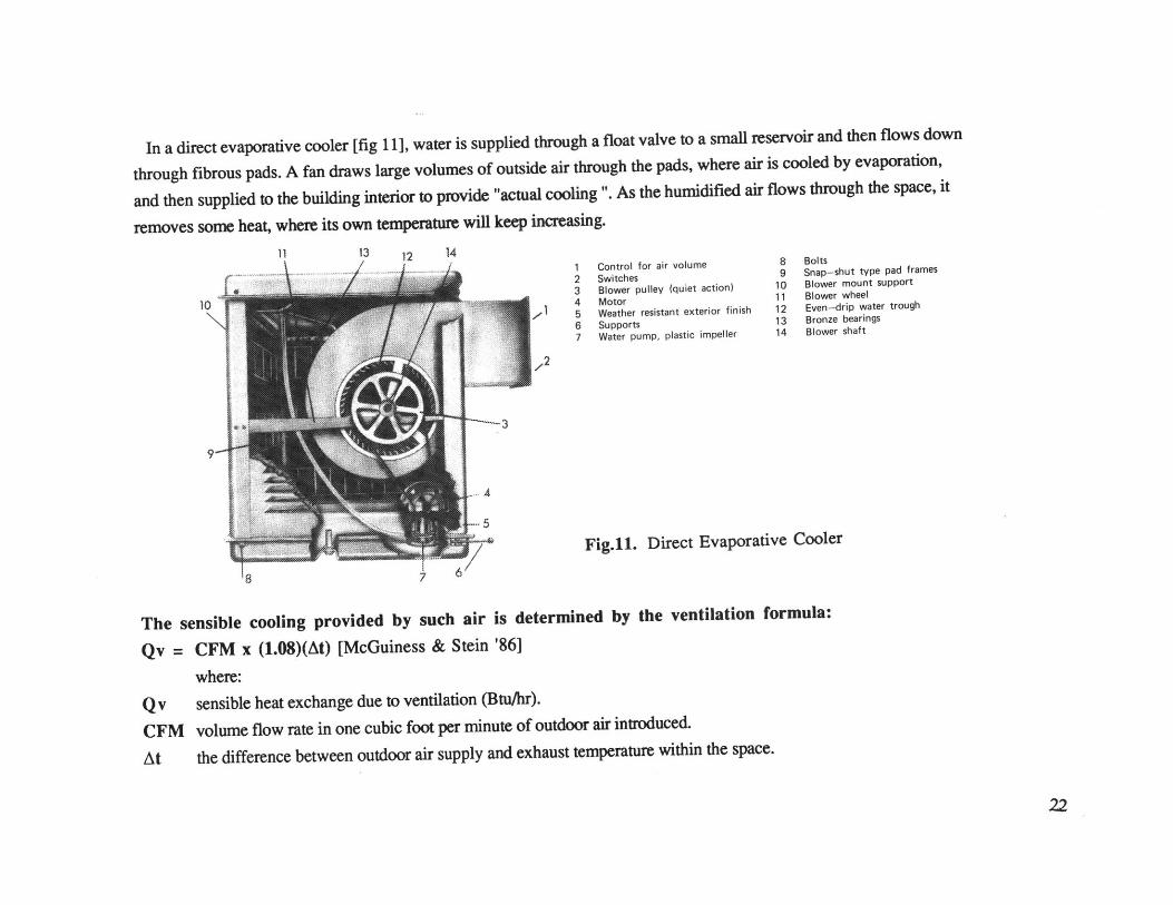
In a direct evaporative cooler [fig 11], water is supplied through a float valve to a small reservoir and then flows down
through fibrous pads. A fan draws large volumes of outside air through the pads, where air is cooled by evaporation,
and then supplied to the building interior to provide "actual cooling ". As the humidified air flows through the space, it
removes some heat, where its own temperature will keep increasing.
11 13 141 - - Crontrol for air volume 8 Bolts234567
SwitchesBlower pulley (quiet action)MotorWeather resistant exterior finishSupportsWater pump, plastic impeller
91011121314
Snap-shut type pad framesBlower mount supportBlower wheelEven-drip water troughBronze bearingsBlower shaft
Fig.11. Direct Evaporative Cooler
8 7
The sensible cooling provided by such air is determined by the ventilation formula:
Qv = CFM x (1.08)(At) [McGuiness & Stein '86]
where:
Qv sensible heat exchange due to ventilation (Btu/hr).
CFM volume flow rate in one cubic foot per minute of outdoor air introduced.
At the difference between outdoor air supply and exhaust temperature within the space.
22
10

Typically, evaporative cooling units are roughly the same size or slightly larger than an air-conditioner's condensing
unit of similar cooling capacity. They are normally mounted on the roof to blow down into the building, however, some
units are window mounted.
Realistic Evaporative Cooling Processes [Abrams '86 ]
The capacity of an evaporative cooler to cool and humidify the air it supplies is measured by the saturation efficiency*Es = DBTin - DBTout x 100%
WBdepression
where: Es = saturation efficiency %
DBTin = dry bulb temperature of entering air *F
DBTout = dry-bulb temperature of leaving air *F
WBdepression = wet-bulb depression for entering air *F
= (dry bulb temp - wet bulb temp) for entering air *F.
The temperature of the air delivered by an evaporative cooler may be estimated with the following equation:
Tsupply = TDBout - (WBdepression x Es)
OR Tsupply = TDBout - (TDBout - TWBout) x Es
where: Tsupply = dry-bulb temperature of air supplied by cooler *F
TDBout = outdoor dry-bulb temperature *F
TWBout = outdoor wet-bulb temperature *F
WBD = wet-bulb temperature depression *F.
Using the typical saturation efficiency of most cores, this equation can be rewritten as:
Tsupply = 0.2 TDBout + 0.8 TWBout
*Commercially produced systems provide saturation efficiencies of about 80%, with some types as low as 50% and others as high as 90%.23
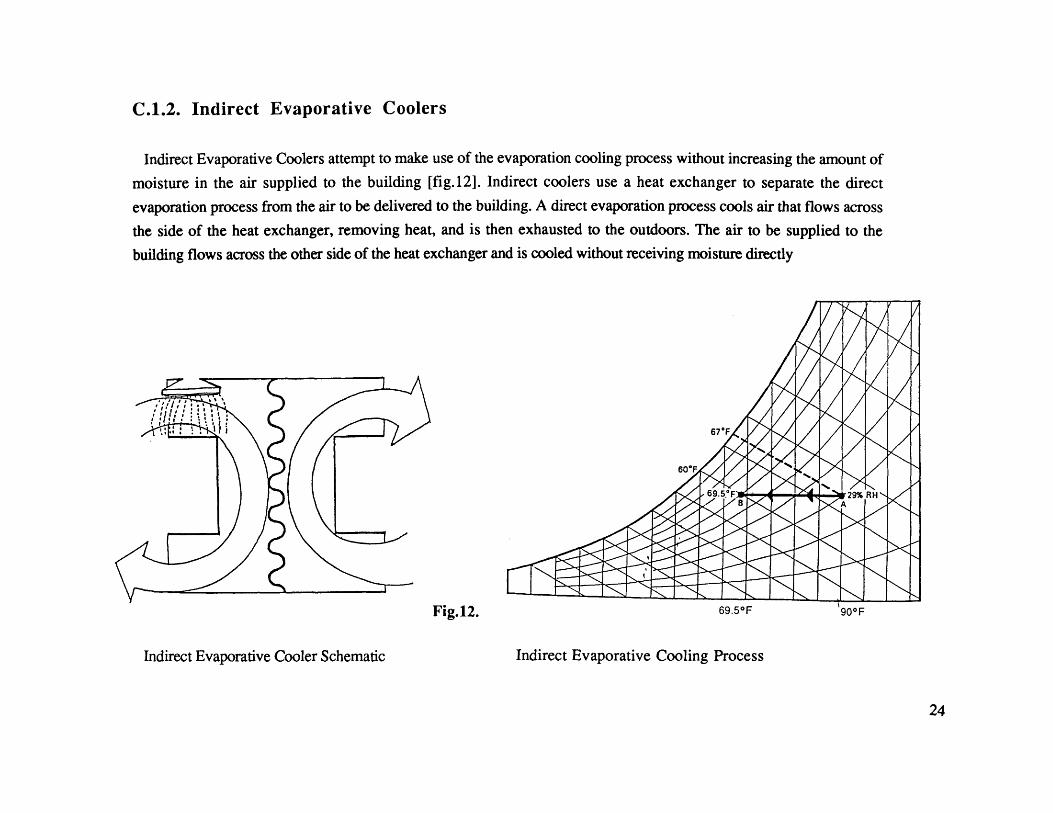
C.1.2. Indirect Evaporative Coolers
Indirect Evaporative Coolers attempt to make use of the evaporation cooling process without increasing the amount of
moisture in the air supplied to the building [fig.12]. Indirect coolers use a heat exchanger to separate the direct
evaporation process from the air to be delivered to the building. A direct evaporation process cools air that flows across
the side of the heat exchanger, removing heat, and is then exhausted to the outdoors. The air to be supplied to the
building flows across the other side of the heat exchanger and is cooled without receiving moisture directly
Fig.12. 69.5 0F 90*F
Indirect Evaporative Cooler Schematic Indirect Evaporative Cooling Process
24
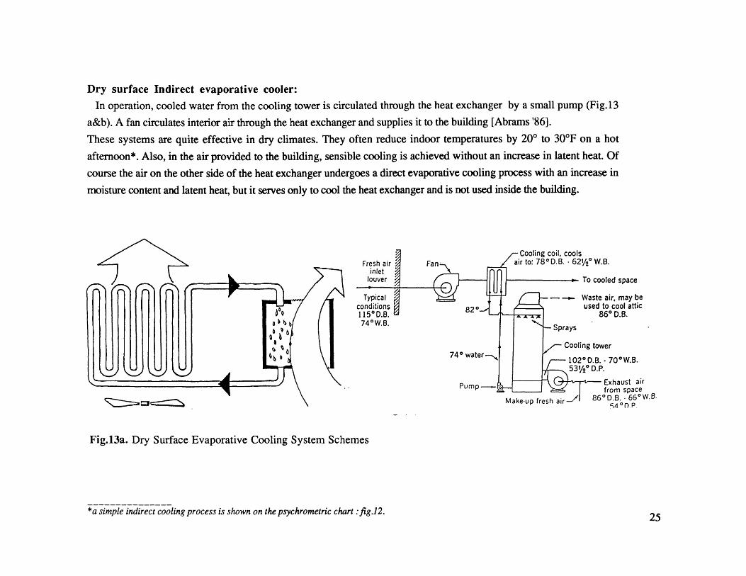
Dry surface Indirect evaporative cooler:In operation, cooled water from the cooling tower is circulated through the heat exchanger by a small pump (Fig.13
a&b). A fan circulates interior air through the heat exchanger and supplies it to the building [Abrams '86].
These systems are quite effective in dry climates. They often reduce indoor temperatures by 200 to 304F on a hot
afternoon*. Also, in the air provided to the building, sensible cooling is achieved without an increase in latent heat. Of
course the air on the other side of the heat exchanger undergoes a direct evaporative cooling process with an increase in
moisture content and latent heat, but it serves only to cool the heat exchanger and is not used inside the building.
To cooled space
Waste air, may beused to cool attic
860 D.B.
Cooling tower
102 0 D.B. - 700W.B.53%0 D.P.
Exhaust airfrom space
Make-up fresh air_/ 860D.B. - 660W.B.5 4 0 P.
Fig.13a. Dry Surface Evaporative Cooling System Schemes
*a simple indirect cooling process is shown on the psychrometric chart :fig.12. 25
Coil water - Pipe coil in pan andpump spray impact zone
Towerwaterpump
WITH EXTERNAL SIMPLE COIL-HEAT EXCHANGER, SHED TOWER
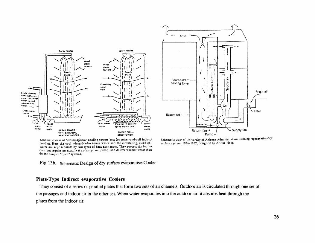
Schematic view of "closed-sy~tem" cooling towers best for toWer-and-coil indirectcooling. Here the cool mineral-laden tower water and the circulating, clean coilwater are kept separate by two types of heat exchanger. They protect the indoorcoils but require an extra heat exchange and pump, and deliver warmer water thando the simpler "open" systems,
Pump-'
Schematic view of University of Arizona Administration Building regenerative dry-
surface system, 1936-1952, designed by Arthur Hess.
Fig. 13b. Schematic Design of dry surface evaporative Cooler
Plate-Type Indirect evaporative Coolers
They consist of a series of parallel plates that form two sets of air channels. Outdoor air is circulated through one set of
the passages and indoor air in the other set. When water evaporates into the outdoor air, it absorbs heat through the
plates from the indoor air.
26
Spray nozzles
Coil Towerwater waterpump pump SPRAY TOWER
Spray nozzles

C.1.3. Two-Stage Evaporative Coolers
Two-Stage evaporative cooling offers significant performance improvements over indirect evaporative cooling system.
The two-stage evaporative cooling system combines Indirect evaporative cooling in the first stage which supplies
precooled air to the Direct evaporative cooling system in the second stage [Sharag Al-din '88].
First stage: Pre-cooling Unit (A-D-E-F)
Outside air flows between dry plates or through plastic tubes surrounded by a wet pad or cloth. The surrounding wet pad
is cooled by evaporation, when air is blown over them (by means of wind, electric fan, or solar chimney). The outside
air between the plates is then cooled by conduction without increasing its moisture content [fig.14].
Second Stage: Direct Evaporative Cooler (F-I-J)
(F-I) This stage can bring the indoor conditions to the thermal comfort zone.
(I-J) As the supply of air draws heat from the space, it will increase its temperature.
o'" iout90 70 50%RH3NEW TY ~ CONVENTIONAL90 750RPEECOOII ,aEAOIT COOLER
IS STAGE I 71 DE 30WET All
A A'
ASHRAE STANDARDWATER SPlAY ' 55-74 COMFORT ZONE.
OUTUT SDEU ToN 8 72 76 79 85 88 107AIR U~PSAllDRY-BULB TEMPERATURE *F
Fig.14. Two-Stage Evaporative Cooler
27
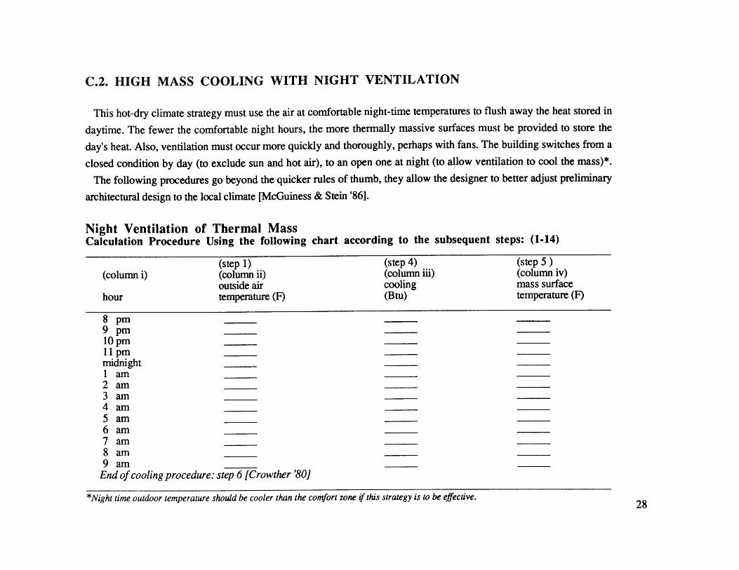
C.2. HIGH MASS COOLING WITH NIGHT VENTILATION
This hot-dry climate strategy must use the air at comfortable night-time temperatures to flush away the heat stored in
daytime. The fewer the comfortable night hours, the more thermally massive surfaces must be provided to store the
day's heat. Also, ventilation must occur more quickly and thoroughly, perhaps with fans. The building switches from a
closed condition by day (to exclude sun and hot air), to an open one at night (to allow ventilation to cool the mass)*.
The following procedures go beyond the quicker rules of thumb, they allow the designer to better adjust preliminary
architectural design to the local climate [McGuiness & Stein '86].
Night Ventilation of Thermal MassCalculation Procedure Using the following chart according to the subsequent steps: (1-14)
(step 1) (step 4) (step 5 )(column i) (column ii) (column iii) (column iv)
outside air cooling mass surfacehour temperature (F) (Btu) temperature (F)
8 pm9 pm10 pm11 pm_midnight1 am2 am3 am4 am5 am6 am7 am8 am9 amEnd of cooling procedure: step 6 [Crowther '80]
*Night time outdoor temperature should be cooler than the comfort zone if this strategy is to be effective.28
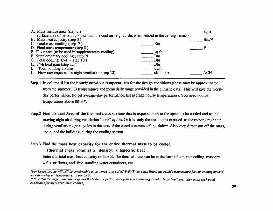
A. Mass surface area (step 2 )surface area of mass in contact with the cool air (e.g: air ducts embedded in the ceiling's mass)
B. Mass heat capacity (step 3)C. Total mass cooling (step 7) BtuD. Final mass temperature (step 8)E. Floor area (to be used in supplementary cooling): sq.ftF. Supplementary cooling ( step 9) BtuG. Total cooling (C+F ) (step 10) BtuH. 24-h heat gain (step 11) BtuI. Total building volume: cu.ftJ. Flow rate required for night ventilation (step 12) cfm or
sq.ft
Btu/F
F
ACH
Step. 1 In column ii list the hourly out-door temperatures for the design conditions (these may be approximated
from the summer DB temperatures and mean daily range provided in the climatic data). This will give the worst-
day performance. (to get average-day performance, list average hourly temperatures). You need not list
temperatures above 80*F *.
Step.2 Find the total Area of the thermal mass surface that is exposed both to the space to be cooled and to the
moving night air during ventilation "open" cycles. Or it is only the area that is exposed to the moving night air
during ventilation open cycles in the case of the cored concrete ceiling slab**. Also keep direct sun off the mass,
and out of the building, during the cooling season.
Step.3 Find the mass heat capacity for the entire thermal mass to be cooled
= (thermal mass volume) x (density) x (specific heat).
Enter this total mass heat capacity on line B. The thermal mass can be in the form of concrete ceiling, masonry
walls or floors, and free-standing water containers, etc.
*For Egypt, people will still be comfortable at air temperature of 83 T-86 'F. So when listing the outside temperature for this cooling methodwe will not list air temperatures above 83 F.**Note that the larger mass area exposed the better the performance (this is why direct-gain solar heated buildings often make such goodcandidates for night ventilation cooling).
29
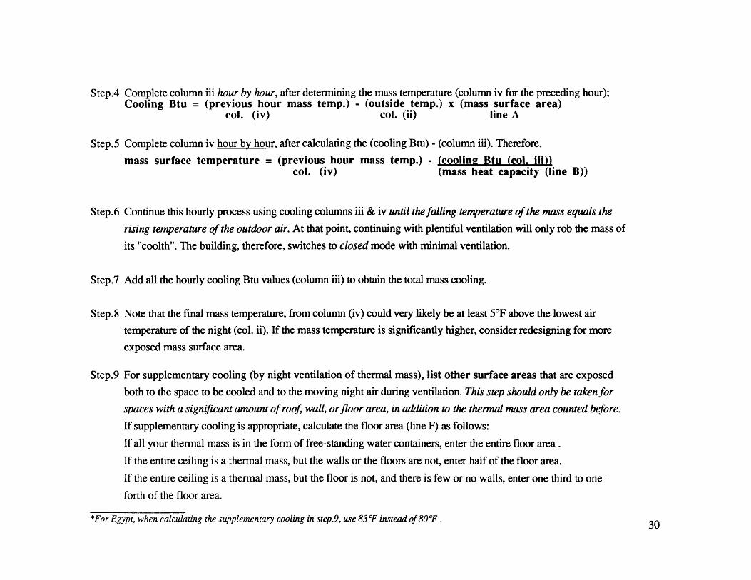
Step.4 Complete column iii hour by hour, after determining the mass temperature (column iv for the preceding hour);Cooling Btu = (previous hour mass temp.) - (outside temp.) x (mass surface area)
col. (iv) col. (ii) line A
Step.5 Complete column iv hour by hour, after calculating the (cooling Btu) - (column iii). Therefore,mass surface temperature = (previous hour mass temp.) - (cooling Btu (col. iii))
col. (iv) (mass heat capacity (line B))
Step.6 Continue this hourly process using cooling columns iii & iv until the falling temperature of the mass equals the
rising temperature of the outdoor air. At that point, continuing with plentiful ventilation will only rob the mass of
its "coolth". The building, therefore, switches to closed mode with minimal ventilation.
Step.7 Add all the hourly cooling Btu values (column iii) to obtain the total mass cooling.
Step.8 Note that the final mass temperature, from column (iv) could very likely be at least 5*F above the lowest air
temperature of the night (col. ii). If the mass temperature is significantly higher, consider redesigning for more
exposed mass surface area.
Step.9 For supplementary cooling (by night ventilation of thermal mass), list other surface areas that are exposed
both to the space to be cooled and to the moving night air during ventilation. This step should only be takenfor
spaces with a significant amount of roof, wall, or floor area, in addition to the thermal mass area counted before.
If supplementary cooling is appropriate, calculate the floor area (line F) as follows:
If all your thermal mass is in the form of free-standing water containers, enter the entire floor area.
If the entire ceiling is a thermal mass, but the walls or the floors are not, enter half of the floor area.
If the entire ceiling is a thermal mass, but the floor is not, and there is few or no walls, enter one third to one-
forth of the floor area.
*For Egypt, when calculating the supplementary cooling in step.9, use 83 F instead of 80 F . 30

Supplementary cooling Btu = [80*F - (final mass temperature: line D)] x 2.25 x (floor area)
The (2.25) factor assumes a modest role for the other, less thermally, massive surfaces. Enter the
supplementary cooling on line F.
Step. 10 Obtain total cooling by adding lines C& F. Enter total on line G.
Step. 11 Calculate the 24-h heat gain for the building in Btu. Find the sum of all the hourly heat gains through the
envelope, the minimum ventilation (while closed), and the internal gains (while operating). Enter the 24-h heat
gain for the building on line H. Compare this cooling Btu needed to the total provided (line G). If you have not
provided enough cooling, and the final mass temperature is more than 7*F above the lowest night-time
outdoor temperature, consider redistributing the building mass over a wider surface (ex: 3000 sq.ft of 4" slab
rather than 2000 sq.ft of 6" slab), and try it again. If you don't have enough cooling (the final mass temperature
is 5*F to 7*F above the lowest night-time outdoor temperature) consider providing both more mass and more
surface area (ex: 3000 sq.ft of 4" slab rather than 2000 sq.ft of 4" slab), and try it again.
Step.12 Determine and enter on line I the approximate flow required for night ventilating air. Use the formula:
cfh = (Btu/h) / 0.018 x At
where cfh is the minimum required flow rate of night air; Btu/h is the cooling Btu for the hour of maximum
cooling during the night (col.iii); and At is the temperature difference between the final mass temperature (col. iv)
and the outdoor air (col. ii) for that same hour of maximum cooling.
It is often useful to express this night ventilation flow rate in terms of air changes per hour (ACH).
ACH = cfh requiredbuilding volume (cu.ft)
31

C.3.NATURAL VENTILATION (PROMOTING AIR MOVEMENT WITHIN THE BUILDING)
C.3.1. Motive Force Caused by Wind Blowing onto the Facade
The wind gives rise to positive pressure on the wind-ward side of the building and negative pressure on the lee-ward
side. Pressure conditions are complicated and depends on the shape of the building, the surrounding vegetation,
proximity to other buildings, etc. P. 0. Nylund has shown that wind blowing onto the facade has very little effect on the
flow of ventilating air, provided that the building is in closed mode at day time, and that it is reasonably air-tight
[Erickson '86]. Wind blowing onto the facade has only marginal significance in this respect and is, therefore, of no
further interest.
C.3.2. Thermal Motive Force*
Stack-Effect Ventilation
As air is heated it expands, becoming less dense and tending to rise above nearby cooler air. Warmer air is more
buoyant; it floats on top of the denser cool air. The greater the difference in temperature, the greater the force associated
with the upward flow.
The stack-effect principle may be used to create flow through the building when there is little wind. The basic elements
required for stack-effect flow are the warm column of air, a cool column, and a path for flow between them. The area of
the stack opening has a greater effect on the air flow than both the temperature difference and the height between the
openings. Air flow is directly proportional to the area of the stack and by square root of the temperature difference and
height.
*In a natural ventilation system, the motive force is made up by difference in temperatures between the outside and inside environments incombination with the stack effect.
32

Solar Chimney
To ventilate the building by the use of solar energy (only at day time), a solar chimney is employed. The solar chimney
is used to heat the exhaust air from the building to a temperature higher than that of the outside air, thus creating a
pressure differential which pulls fresh air into and through the building. The interior spaces are air-conditioned as the
incoming air is treated by either active, or passive conditioning equipment.
Solar Chimney System
Discused below is a solar chimney developed by Robert J. Haisley [Haisley '81]. The solar chimney consists of two
integral parts [fig.15]: A solar air heater and a hot air shaft. The solar air heater forms a conduit for air
transmission, for absorption of heat from the sun and for the dissipitation of that heat to the body of air within the heater.
For solar chimney applications, the solar air heater heats the incoming air above the outside air temperature for the
purpose of making a difference in air densities between the contained air and outside air, which in turn causes the, air
being heated, to rise.
n8- - 9
A. Cooling Appliance 0 H 0B. Cold Air Shaft -- - eC. Building Envelope D i _1
D. Solar Chimney t g
Hot air shaft Insulation s h
B (Z) 7W E I
/5~ - - - - 6 54 6 4 3
Solar air heater A. Building Geometry (points B. Static Pressure (P)correspond to those inB )
Air Path Cross section of a Solar Chimney: Pressure changes in the solar chimney system at moderate and high ambient temperature
Fig.15. Solar Chimney System Developed by Robert Haisely 33

The hot air shaft, the second integral part of the chimney, is an insulated open-ended vertical duct, and that is in order
to encroach the height of the column of hot air in the solar air heater.The purpose of this hot air column formed in the
solar chimney is to create an air flow, known as theoretical draft. It is comparable to the motive pressure created in a
gas passage of a heat generating unit; such as a chimney.
Theoretical draft is defined as a static pressure resulting from the difference in weight between two columns of air of
equal heights and at different temperatures.These columns are a column of hot air in the solar chimney and an equal
column of colder, heavier, ambient air. A column of cold air is formed and sustained as the conditioned air falls from the
cooling appliance through the long insulated shaft to the enclosure below.The cool air shaft is an insulated, open-ended,
duct. A pressure differential is created by the difference in weight between the column of cold air and an equivalent
column of ambient air of higher temperature. For the solar chimney system, the term "stack effect" implies the combined
theoretical draft of the two connecting unbalanced columns in the solar chimney and the cold air shafts which are both
under the same atmospheric pressure.
Motive Force due to the Entrainment Effect of Wind at the Top of the S. ChimneyPressure conditions in the chimney are modified by wind velocity at the top of the chimney [Erickson '86]. The usual
consequence is negative pressure which encroaches the airflow rate. This motive force is difficult to calculate. However,
it has been imperically assessed that according to a wind velocity of about 10 m/s, the air change rate in natural
ventilation system can increase by a factor of three or two [Carlson '85].Advantages
- The system is quiet in operation since there are no fans.
- Operation is not affected by power failure.
34
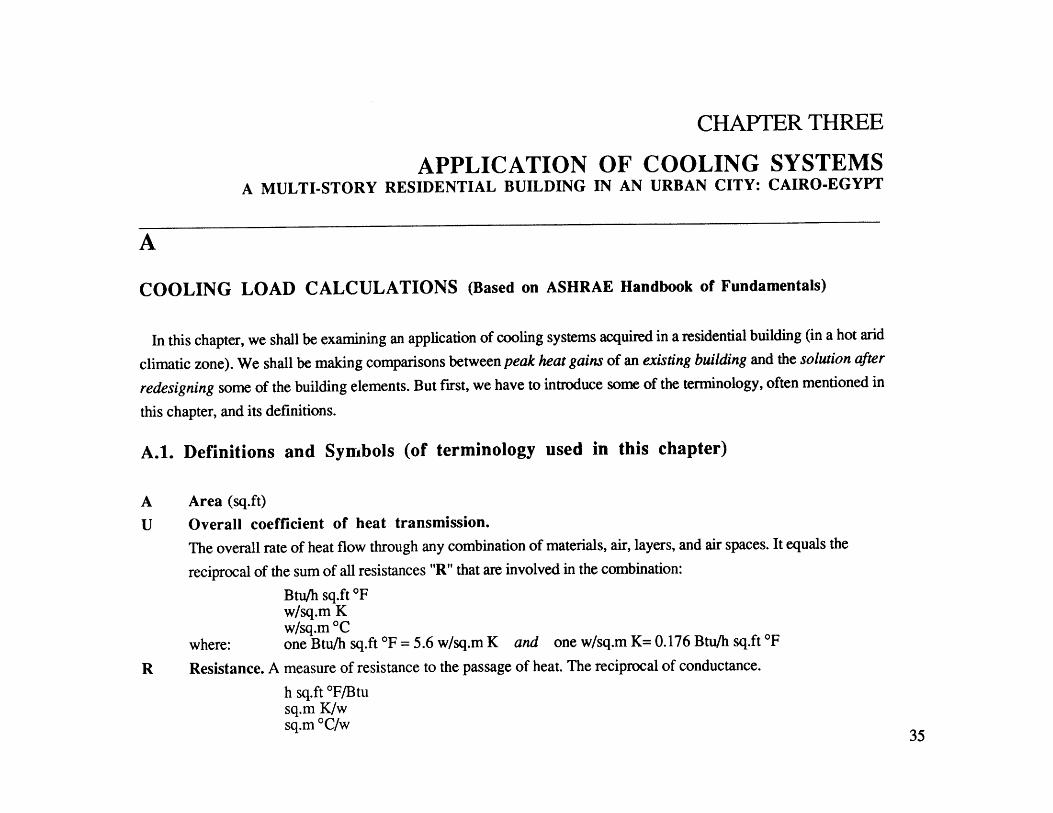
CHAPTER THREE
APPLICATION OF COOLING SYSTEMSA MULTI-STORY RESIDENTIAL BUILDING IN AN URBAN CITY: CAIRO-EGYPT
A
COOLING LOAD CALCULATIONS (Based on ASHRAE Handbook of Fundamentals)
In this chapter, we shall be examining an application of cooling systems acquired in a residential building (in a hot arid
climatic zone). We shall be making comparisons between peak heat gains of an existing building and the solution after
redesigning some of the building elements. But first, we have to introduce some of the terminology, often mentioned in
this chapter, and its definitions.
A.1. Definitions and Symbols (of terminology used in this chapter)
Area (sq.ft)
Overall coefficient of heat transmission.
The overall rate of heat flow through any combination of materials, air, layers, and air spaces. It equals the
reciprocal of the sum of all resistances "R" that are involved in the combination:
Btu/h sq.ft 'Fw/sq.m Kw/sq.m*C
where: one Btu/h sq.ft *F = 5.6 w/sq.m K and one w/sq.m K= 0.176 Btu/h sq.ft *F
Resistance. A measure of resistance to the passage of heat. The reciprocal of conductance.
h sq.ft *F/Btusq.m K/wsq.m *C/w
A
U
R
35
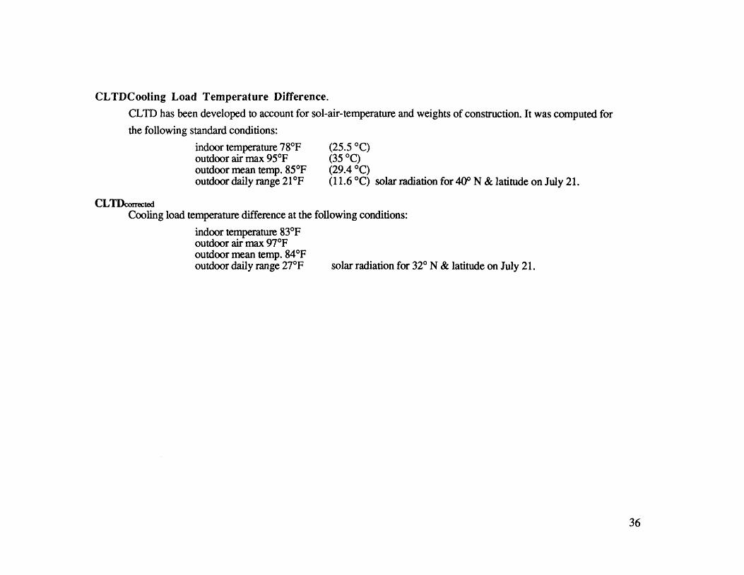
CLTDCooling Load Temperature Difference.
CLTD has been developed to account for sol-air-temperature and weights of construction. It was computed for
the following standard conditions:
indoor temperature 784F (25.5 *C)outdoor air max 95*F (35 *C)outdoor mean temp. 85*F (29.4 *C)outdoor daily range 21*F (11.6 *C) solar radiation for 40" N & latitude on July 21.
CLTDcorrectedCooling load temperature difference at the following conditions:
indoor temperature 83*Foutdoor air max 97*Foutdoor mean temp. 84"Foutdoor daily range 27*F solar radiation for 32" N & latitude on July 21.
36

A.2. Overall Coefficient of Heat Transmission for Roofs
To calculate heat gain through the roof we need to know its Overall Coefficient of heat transmission.
A.2.1. Overall Coefficient of Heat Transmission U value for EXISTING ROOF [fig.16]:
No. Description R U
1 air film: moving air any position 7.5 mph wind for summer 0.252 cement sand tiles 0.053 2" sand 0.154 1.75" cement sand leveling screed 0.355 2" expanded polystyrene 10.006 3 layers bituminous felt 0.1547 4" reinforced concrete slab 0.3338 3/4" cement sand plaster 0.159 airfilm still 0.68
Total R 11.817U value = 1/ (total R) 0.084
Fig.16. Details of the Existing Roof
37
I

A.2.2. Overall Coefficient of Heat Transmission for REDESIGNED ROOF [fig.17]:
No. Description R U
1 air film: moving air any position (7.5 mph wind for summer) 0.252 cement sand tiles. 0.053 2" sand 0.154 1.75" cement sand leveling screed 0.355 2" expanded polystyrene 10.006 3 layers bituminous felt 0.1547 4" reinforced concrete slab 0.3338 3/4" cement sand plaster 0.159 airfilm still 0.6810 2" still air core (horizontal) 2.5
Total R 14.27U value= 1/ (total R) 0.07
Fig.17. Detail of the Redesigned Roof
38

DETAILED HOURLY HEAT GAIN CALCULATIONS (CLTD)LOAD SOURCE EQUATION REMARKSExternal U = Design heat transfer coefficients
A = Area calculated from architectural plansCLTD = Cooling load temperature difference at base conditions for roofs
Roof q= UxA x CLTD Note :Correction for color of exterior surfacesCorrection for outside dry-bulb temperature and daily rangeCorrection for inside dry-bulb temperatureApplication for latitutde and monthU = Design heat transfer coefficientsA = Area calculated from architectural plans (wall construction description)CLTD = Cooling load temperature difference at base conditions for walls
Walls q= UxA x CLTD Note :Convection for color of exterior surfacesCorrection for outside dry-bulb temperature and daily rangeCorrection for inside dry-bulb temperatureApplication for latitutde and month
Glass U for type of glass and interior shading if usedArea, Net glass area calculated from architectural plansCLTD, Cooling load temperature difference for conduction load furu glass
Conduction q = U x A x CLTD Note :Correction for outside dry-bulb temperature and daily rangeCorrection for inside dry-bulb temperatureA = Net glass area calculated from plansSC = Shading coefficients for combination of type of glass and type ofshading
Solar q = A x SC x SHGF x CLF SHGF = Maximum solar heat gain factor for specific orientation ofsurface, latitude, and monthCLF = Cooling load factor with/ without interior shading
Space Cooling Loads Using the CLTD and CLF Method (From ASHRAE 1981 Handbook of Fundamentals).
Table. 1. Summary of Cooling Loads using CLTD and CLF methods
39
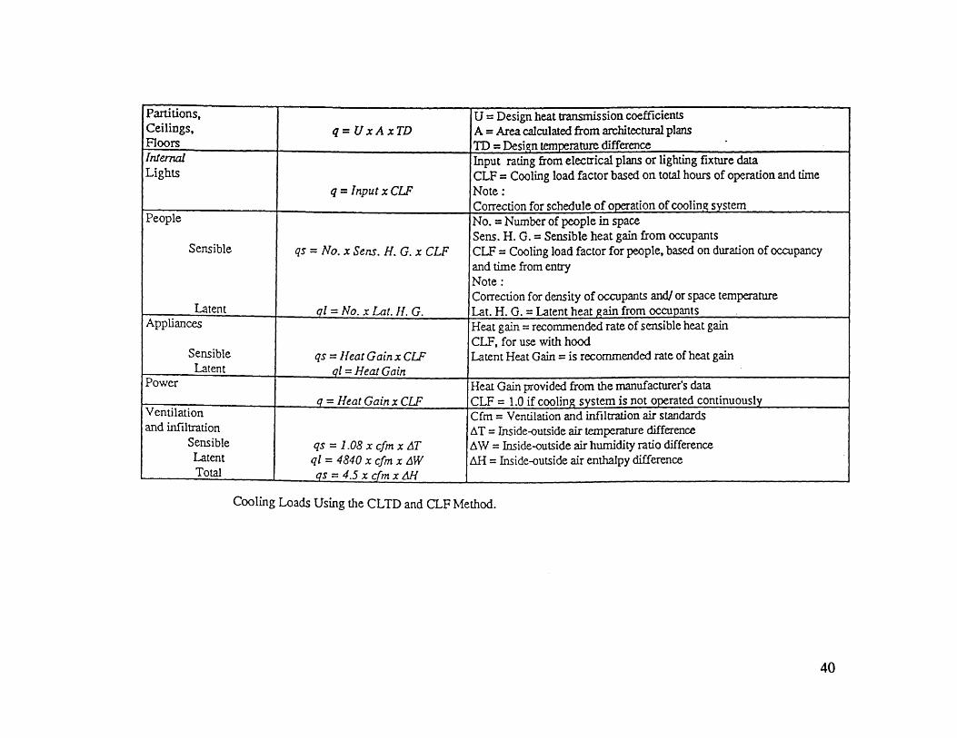
Partitions, U = Design heat transmission coefficientsCeilings, q = U x A x TD A = Area calculated from architectural plansFloor~s__________ ___ TD = Desien temperature differenceInternal Input rating from electrical plans or lighting fixture dataLights CLF = Cooling load factor based on total hours of operation and time
q = Input x CLF Note:
PeopleCorrection for schedule of or~ation of cooling systemPeople No. = Number of people in space
Sens. H. G. = Sensible heat gain from occupantsSensible qs = No. x Sens. H. G. x CLF CLF = Cooling load factor for people, based on duration of occupancy
and time from entryNote:Correction for density of occupants and/ or space temperature
Latent gi = No. x Lat. H. G. Lat. H. G. = Latent heat gain from occupantsAppliances Heat gain = recommended rate of sensible heat gain
CLF, for use with hoodSensible qs = Heat Gain x CLF Latent Heat Gain = is recommended rate of heat gain
Power Heat Gain provided from the manufacturer's data
VetltinqHeat Gain x CU' CLF 1.0 if cooling system is not operated continuouslyVentilation Cfm= Ventilation and infiltration air standardsand infiltration AT = Inside-outside air temperature difference
Sensible qs = 1.08 x cfm x AT AW = Inside-outside air humidity ratio differenceLatent ql = 4840 x cfm x AW AH = Inside-outside air enthalpy differenceTotal L s =4.s x cfmxA and CLFIMetho
Cooling Loads Using the CLTD and CLF Method.
40

A.2.3. Peak Heat Gain for the EXISTING BUILDINGExternal Roof (ONE floor per ONE hour) Q = A x U x CLTDcorrected
A U CLTD correction CLTDcort'd QLM K Tin Tout F
2800 0.084 53 1 0.5 -5 -1 1 21 4,939.2
A Floor area (4 apartments) sq.ft
U Overall coefficient of heat transmission Btu/sq.ft *F h.
CLTDmax Cooling load temperature difference (40' N). 'F roof no. 9:
4" heavy weight concrete
2" insulation [McGuiness & Stein table5-28] CLTD for flat roofs.
CLTDcorrect'n Max. cooling load temperature difference in existing building (Cairo 30* latitude in the month of July).
LM: Latitude-month correction for lat. 32*N in July (nearest latitude to Cairo ) [McGuiness & Stein'86].
K: is the color adjustment factor and is applied after making latitude-month adjustments.
Tin: (78-TR) indoor design temperature correction, where TR=indoor temperature (TR=834F).
Tout: (To-85) outdoor design temperature correction;To=average outside temperature on design day.
To=97*F - (daily range (264F))/2.
To=84 and Tout-(84-85)=-1.
F: factor for attic and/or ducts above ceiling applied after all other adjustments have been made
F=1.0 (no attic ducts).
F=0.75 (positive ventilation) [McGuiness & Stein table 5-2].
Therefore, CLTDort'd = (CLTD+LM) x K + (78-TR) + (To-85) x F= (53+1) x 0.5 + (-5) + (-1) x 1 = 21*F.
41
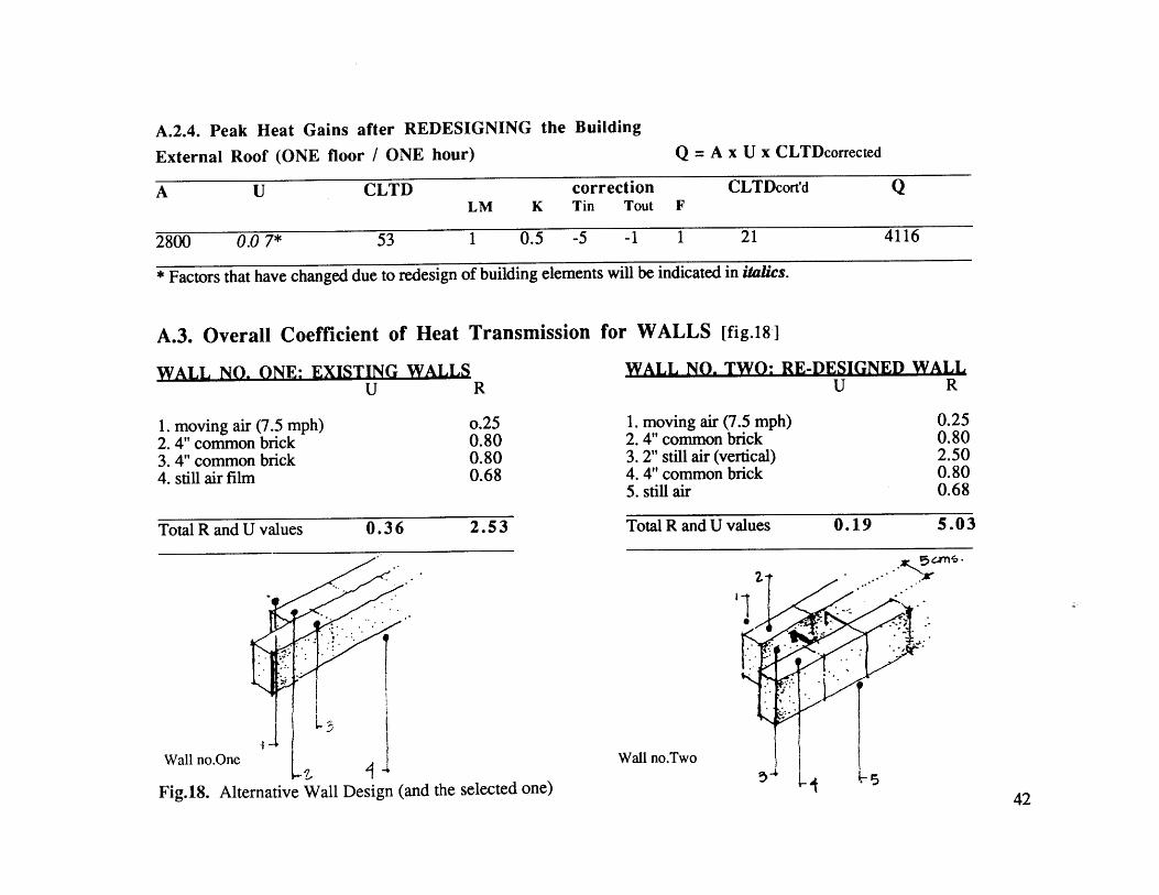
A.2.4. Peak Heat Gains after REDESIGNING the Building
External Roof (ONE floor / ONE hour) Q = A x U x CLTDcorrected
A U CLTD correction CLTDcort'd QLM K Tin Tout F
2800 0.0 7* 53 1 0.5 -5 -1 1 21 4116
* Factors that have changed due to redesign of building elements will be indicated in italics.
A.3. Overall Coefficient of Heat Transmission for WALLS [fig.18]
WALL NO. ONE: EXISTING WALLSU R
1. moving air (7.5 mph)2. 4" common brick3. 4" common brick4. still air film
o.250.800.800.68
Total R and U values 0.36 2.53
Wall no.One
.- ~. 9.:* 4
Ii,
WALL NO. TWO: RE-DESIGNED WALLU R
1. moving air (7.5 mph)2. 4" common brick3. 2" still air (vertical)4. 4" common brick5. still air
0.250.802.500.800.68
Total R and U values 0.19 5.03
ZZN
Wall no.Two
Fig.18. Alternative Wall Design (and the selected one)42

COMPARISON BETWEEN THE U VALUES OF OTHER WALL TYPES
WALL NO, THREE:
1. moving air (7.5 mph)2. 4" common brick3. 4" cored cinder-block (3 holes)4. still air
U R
0.250.801.100.68
WALL NO, FOUR:
1. moving air (7.5 mph)2. 4" common brick3. 2" expanded polystyrene4. 4"common brick5. still air
Total R and U values 0.35 2.83
Wall no. Threez.
Total R and U values 0.076 13.06
Wall no.Four
U R
0.250.8010.530.800.68
43
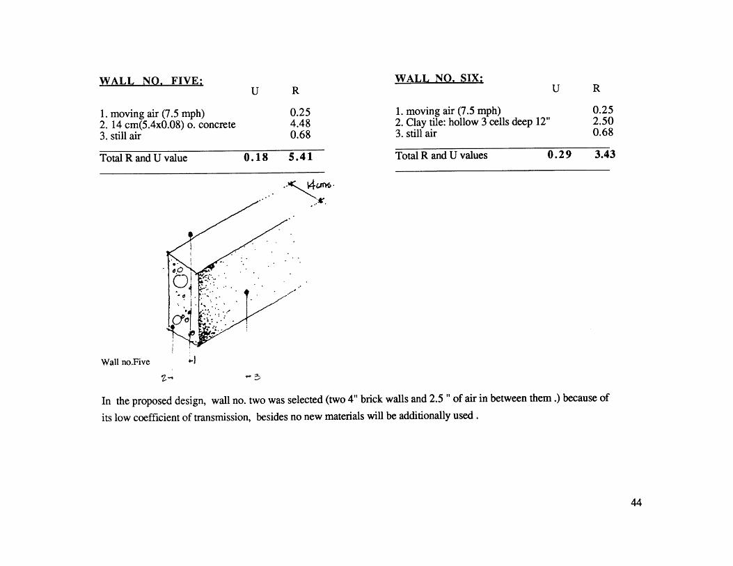
WALL NO, FIVE:U R
1. moving air (7.5 mph)2. 14 cm(5.4x0.08) o. concrete3. still air
0.254.480.68
Total R and U value 0.18 5.41
Wall no.Five
1. moving air (7.5 mph)2. Clay tile: hollow 3 cells deep 12"3. still air
Total R and U values 0.29 3.43
'-I
%
In the proposed design, wall no. two was selected (two 4" brick walls and 2.5 " of air in between them.) because of
its low coefficient of transmission, besides no new materials will be additionally used.
44
U R
0.252.500.68
WALL NO, SIX;

A.3. Heat Gain through GlassA.3.1. Peak Heat Gain through GlassFor ONE floor / ONE hour
by Solar Radiation in EXISTING Building*Q = A x SHGF x SC x CLF
Orien. A SHGF SC CLF QNorthern edge of the buildingNW 110 167 1 0.3 5511SW 22 150 1 0.75 6187.5SE 55 150 1 0.28 2310NE - - - - -Southern edge of the buildingNW 55 167 1 0.3 2755.5SW 22 150 1 0.75 2475SE 110 150 1 0.28 4620NE - - - - -
Heat Gain From Glass by Solar Radiation 23,859 Btu/hrTotal Heat Gain From Glass (Rad. & conduction.) 27113.4 Btu/h
A Net glass area calculated from plans (sq.ft).
S HG F Solar Heat gain factor due to solar radiation (Btu/h sq.ft) for sun lit glass -north latitude [McGuiness &Stein tables 5.34/5.36 for maximum hour of radiation].
S C Shading Coefficient = (solar heat gain from fenestration)(Solar heat gain of double strength glass)
CLF Cooling Load Factor.
This factor must be used along with SHGF to account for the delay in the impact of incoming solar
radiation on the air temperature of a cooled space [McGuiness & Stein tables 5.43/5.44 calculated at 14:00
solar time, with interior shading).
*Detailed calculations for peak heat gain form walls, and from glass by conduction before and after redesigning is in appendix A.. Also,calculations for the existing solution is based on a window with no external shading devices.
45

A.3.2. Peak Heat Gain through Glass by Solar Radiation after REDESIGN
For ONE floor per ONE hour [fig.19] Q=A x SHGF x SC x CLF
Orien. A SHGF SC CLF QNorthern edge of the buildingNW 110 167 0.25 0.3 1377.75SW 22 150 0.25 0.75 618.75SE 55 40 0.25 0.28 154NE 11 167 0.25 0.24 110Southern edge of the buildingNW 55 40 0.25 0.3 165SW 22 150 0.25 0.75 618.7SE 110 150 0.25 0.28 1155NE* 11 167 0.25 0.24 110
Heat Gain From Glass by Solar RadiationTotal Heat Gain From Glass (Rad. & cond.)
Diagonal Shading Device is Selected for the Design
(Refer to appendix for details)
4,309.2 Btu/hr7,746.4 Btu/hr
Fig.19a. SOUTH EAST AND NORTH WEST ORIENTATION Jjjj*Windows are added in the north east (NE) side of the facade in the northern and southern edge of the building.
46

Fig.19b. SOUTH AND SOUTH WEST ORIENTATION
Egg-Crate with Window Depth Equals to 1/3- 2/3 Dimension of the Window is the BestShading Device for this Orientation
Fig.19c. WEST AND EAST ORIENTATION
Horizontal and vertical fins tilted 45 degrees to the south is the best shading device for this orientation47

A.4. Peak Sensible Heat Gain from peopleQ = number of people/one floor x heat gain x CLF
no. of people CLF heat gain/person Q
Sensible Heat 20 0.92 225 4,140
Total SENSIBLE Heat Gain from people 4,140
A.5. Peak Heat Gain from INTERNAL Light
For one floor per one hour [Johnson '81] Q = Input x CLF (Btu/Kwh = kw x 3400)
INPUT CLF Q
input/day (8 hours) / one family (Kw) 5.5input/day (8 hours) / one family (Btu/Kwh) 18700input/day (8 hours) / 4 families (Btu/Kwh) 74800input / one hour / 4 families (Btu/Kwh) 9350 0.56 5,236
CLF Cooling load factor.
We assume that energy supplied to lights becomes immediate heat gain. However, this is often untrue.
Light component raises air temperature only after it has been absorbed and released by the materials in the
space. Thus cooling load factors are necessary to account for this lag. Given information about the type of
furnishing, the air supply and return, the type of electrical lights [McGuiness & Stein table 5.45] , the type of
room envelope, and the air circulation; the actual CLF can be computed. Note that Peak heat gain from electric
lights is reached after 2 hours of usage.
48

A.6. Summary of PEAK HEAT GAINComparison between the existing & recommended solutions after redesigning certain elements
EXISTING BUILDING AFTER REDESIGNING
Roof 4,939.2 4,116Wall* 20,652 10,917.5Glass conduction* 3,254.4 3,437.2Glass solar radiation 23,859 4,309.2People 4,140 4,140Electric Lights 5,236 5,236
Total heat gain per hour 62,080.6 28,285.4 (45.5% red. in cooling loads)
A.8. SUMMARY OF HEAT GAINS (For one floor: 4 apartments )
HEAT GAIN HEAT GAIN** HEAT GAIN HEAT GAIN HEAT GAIN HEAT GAINfor one hour for one hour for 12 h for 12 h for 12 h for 24 h
DAY-TIME DAY-TIME NIGHTTIME NIGHT & DAYTIMEBased on Based on based on based on based on based onPEAK calc. AVERAGE calc. AVERAGE calc. PEAK calc AVERAGE calc. AVERAGE calc.
Roof 4,116 3,822 45,864 49,392 45,864Wall 10,917 7,495 89,940 131,004 89,940Glass conduction 3,437.2 -164.724 -1,976.6 41,246 -1,976.6Glass solar radiation 4,309 7,385 88,624 51,708 88,624People 4,140 4,140 49,680 49,680 49,680 99,360Electric Lights 5,236 5,236 10,472 10,472 31,408 41,880
Total 28,285.4 27,913.3 282,603 28,285.4 81,088 363,691latent heat gain (299/person/h) 5,980 5,980 71,760 71,760 71,760 143,520
Total heat gain(sensible&latent: 4 apts) 34,265.4 33,893.3 354,363 405,262 152,848 507,211
* Refer to appendixfor detailed calculations**Refer to the appendicesfor average heat gain calculation
49

B
SELECTING COOLING SYSTEMSBy Applying Cairo's Summer Design Data on the Bioclimatic Chart
When plotting the climatic conditions of Cairo /Egypt on the Bio-climatic chart [fig.20], we find that the temperature-
humidity combination lies above the shading line*, and these conditions can be made comfortable by Evaporative
coolers, natural ventilation and High mass cooling with night ventilation (explained in chapter two). Each
of these cooling system, and a combination of them will be examined later in the section to follow [Nicholson '76].
moiofor VA.1i i
4,A - ~ 0 &J,/rFig.20. Plotting Cairo's Summer Time Design Conditions on the
Bioclimatic Chart to Determine the Cooling System that Will Be Used&A 10% W Y.
RedlAtive Hu~miditil
*summer design data: DBT1%-2.5% = 97*F; WBT2.5% =75*F;RH = 35% at day time (from the psychrometric chart).50
4
50y. 40%/ 0 Aw 607. -W7.X V

C
COOLING SYSTEMS AND SCHEMES
High mass cooling with night ventilation, Evaporative coolers, and Natural Stack Ventilation, are
the used cooling systems for such a context. Each of these cooling systems, and a combination of them will be
examined and sized. Several cooling schemes can be used for cooling the building passively, or perhaps with minimum
energy [fig.2 1]. The research procedure is described as follows:
C.1. SCHEME ONE*
Examining whether the use of a thermal mass (cored concrete slab) flushed with night ventilation
will remove the 24-hour heat gain or not.
First we shall estimate the size of the thermal mass and the air ducts embedded in it .And by following the step-by-
step method for cooling with forced night ventilation through the thermal mass (described in chapter one), we can
calculate the total heat removed form each apartment, and the duration of operating this cooling system. In addition, we
can also compute the volume rate of air "cfm" needed to achieve this cooling load.
If this scheme did not succeed to remove the 24-hour average heat gain, it may succeed to remove the average heat
gain generated during the closed mode at day time. If that was not fullled either, change the size of the thermal mass,
or switch to another cooling scheme
*The average heat gainfor 24 hour (of the building envelope, people, and artificial lighting) is the heat gain used in this cooling scheme.Refer to chapter twofor details
51

Night Time
Scheme One
Scheme Two
Scheme Three
Scheme Four
Fig.2 1. Schematic Design of the Cooling Schemes52
lop
'Mill I I Iff] I I III III I I I I I Iff
Day Time

I &
ff4744
LJ7/~
* *.a%.
Ii***.***'.I-
I-sit'd
L 7..(~%A$$ ~ACA1~~~
Fig.22. Dimension of the Proposed Cored Slab
53
-4L.A-r1c4-4
+L
cT.mv .
4AZI
N
I I
I
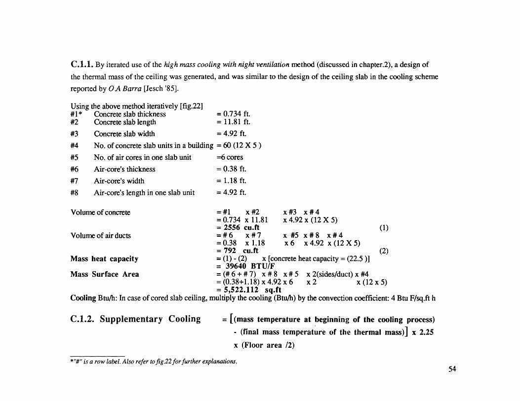
C.1.1. By iterated use of the high mass cooling with night ventilation method (discussed in chapter.2), a design of
the thermal mass of the ceiling was generated, and was similar to the design of the ceiling slab in the cooling scheme
reported by QA Barra [Jesch '85].
the above method iteratively [fig.22]Concrete slab thicknessConcrete slab length
Concrete slab width
No. of concrete slab units in a building
No. of air cores in one slab unit
Air-core's thickness
Air-core's width
Air-core's length in one slab unit
= 0.734 ft.= 11.81 ft.
= 4.92 ft.
= 60 (12 X 5)
=6 cores
= 0.38 ft.
= 1.18 ft.
= 4.92 ft.
Volume of concrete =#1 x #2 x#3 x#4= 0.734 x 11.81 x 4.92 x (12 X 5)= 2556 cu.ft (1)
Volume of air ducts =#6 x # 7 x #5 x#8 x#4= 0.38 x 1.18 x 6 x 4.92 x (12 X 5)= 792 cu.ft (2)
Mass heat capacity = (1) - (2) x [concrete heat capacity = (22.5)]= 39640 BTU/F
Mass Surface Area =(#6+#7) x#8 x#5 x 2(sides/duct)x#4= (0.38+1.18) x 4.92 x 6 x 2 x (12 x 5)= 5,522.112 sq.ft
Cooling Btu/h: In case of cored slab ceiling, multiply the cooling (Btu/h) by the convection coefficient: 4 Btu F/sq.ft h
C.1.2. Supplementary Cooling = [(mass temperature at beginning of the cooling process)
- (final mass temperature of the thermal mass)] x 2.25
x (Floor area /2)
*"#" is a row label. Also refer toflg.22forfurther explanations.54
Using#1*#2
#3
#4
#5
#6
#7
#8

C.1.3. Forced Night Ventilation Of Thermal Mass (Cored Concrete Ceiling Slab)
Hour T(out) 'F Cooling Btu / hour Mass Temperature (F)
20 84.9 none21 83.55 none 83.5522 82.2 4 x (83.50-82.20) x 5522 = 28,714.4 83.55 - (28,714.4/39,646) = 82.8223 80.85 4 x (82.82-80.85) x 5522 = 43,513.36 82.82 - (43,513.3/39,646) = 81.7324 79.5 4 x (81.73-79.50) x 5522 = 49,256.2 81.73 - (49,256.0/39,646) = 80.481 78.15 4 x (80.48-78.15) x 5522 = 51,465.04 80.48 - (51,465.0/39,646) = 79.182 76.8 4 x (79.18-76.80) x 5522 = 52,606.7 79.18 - (52,606.7/39,646) = 77.853 75.4 4 x (77.85-75.40) x 5522 = 54,179.36 77.85 - (54,179.3 /39,646) = 76.484 76.0 4 x (76.48-76.00) x 5522 = 10,602.24 76.48 - (10,602.2/39,646) = 76.205 78.4 STOP
Total mass cooling = 290,000 BtuFinal mass temperature = 76.20 'F
Therefore, supplementary cooling becomes
Total cooling
= (83.55 -76.2) x (2.25)x= 23,152.5 Btu=23,152.5 + 290,000=313,152 Btu
floor area (2800/2)
24-hour heat gain(sensible heat gain only) =363,691 Btu12-hour heat gain =282,603 BtuApproximate flow required for night ventilating air equals cfm = 54179 maximum cooling Btu/h
60 X 0.018 (At)(76.4-75.4 )
CFM
ACM
=50,165 sq.ft/ min/ 4 apartments=12,541 f/ min/ one apartments=12,541/5600=2.2 air change per minute *
This scheme ONE failed, theoretically, to remove the 24-hour heat gain (closed and open modes). But it can remove
the heat gain at day time during when the building is closed to the outside environment. This method is used later in
scheme three.C.2. SCHEME TWO
55
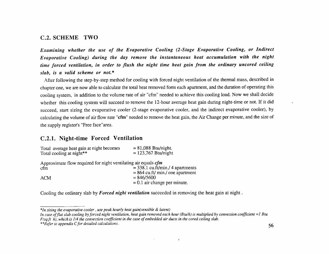
C.2. SCHEME TWO
Examining whether the use of the Evaporative Cooling (2-Stage Evaporative Cooling, or Indirect
Evaporative Cooling) during the day remove the instantaneous heat accumulation with the night
time forced ventilation, in order to flush the night time heat gain from the ordinary uncored ceiling
slab, is a valid scheme or not.*
After following the step-by-step method for cooling with forced night ventilation of the thermal mass, described in
chapter one, we are now able to calculate the total heat removed form each apartment, and the duration of operating this
cooling system, in addition to the volume rate of air "cfm" needed to achieve this cooling load. Now we shall decide
whether this cooling system will succeed to remove the 12-hour average heat gain during night-time or not. If it did
succeed, start sizing the evaporative cooler (2-stage evaporative cooler, and the indirect evaporative cooler), by
calculating the volume of air flow rate "cfm" needed to remove the heat gain, the Air Change per minute, and the size of
the supply register's "Free face"area.
C.2.1. Night-time Forced Ventilation
Total average heat gain at night becomes = 81,088 Btu/night.Total cooling at night** = 123,767 Btu/night
Approximate flow required for night ventilating air equals cfmcfm = 338.1 cu.ft/min./ 4 apartments
= 864 cu.ft/ min./ one apartmentACM = 846/5600
= 0.1 air change per minute.
Cooling the ordinary slab by Forced night ventilation succeeded in removing the heat gain at night .
*In sizing the evaporative cooler , use peak hourly heat gain(sensible & latent)In case offlat slab cooling by forced night ventilation, heat gain removed each hour (Btulh) is multiplied by convection coefficient =1 BtuF/sq ft h), which is 1/4 the convection coefficient in the case of embedded air ducts in the cored ceiling slab.**Refer to appendix Cfor detailed calculations. 56

C.2.2. Day-time Use of Evaporative CoolersTwo stage evaporative coolers* will supply dwellings with air characterized by low temperatures (TDB = 83*F ), but
rather with relatively a high relative humidity (RH=65%). However, if we use the indirect evaporative cooler, we can
achieve another level of comfort with higher temperatures (TDB = 874F), and reasonable relative humidity (RH=50%).
Using 2-stage Evaporative Cooling [fig.23]
Peak heat gain per apartment = 8,566.35 Btu. (Summer; June 21).
First-Stage Indirect cooling:
Tsuppiy = TDBout - (TDBout - TWBout) x Es**TDB = 97 - (97 - 75) x 0.82
= 78.96*F
As the supply of air draws heat from the space, it will increase its temperature by 4*F, and it becomes 82.96*F. And
when the supply of air passes through the heat exchanger, it will increase its temperature by an additional 4*F.
Therefore, the final air supply temperature becomes = 78.96 + 8
=86.96*F
When plotting [Tsupply (final)] on the psychrometric chart, 86.96*F dry bulb temperature corresponds to 50 % relative
humidity. Also, we can have almost the same temperature of supply air when using the psychrometric chart.
BDT RH% WBT
A outside conditions (day time) 97 35 75D after the cooling process through the heat exchange of the first stage 87 50 72E Second-stage supply 79 76 72F second-stage exhaust 83 65 73.5
*use the peak hourly heat gain when sizing cooling equipments.**Es = saturation efficiency %. Refer to Chapter two for theory.
57

30 2 0 M 4 4 0 i 0 6 0 75 80 85 go too 1W a 11
Fig.23. Plotting Two Stage Evaporative Cooling Process on Psychrometric Chart
58
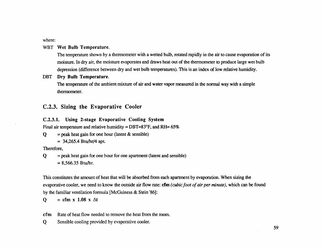
where:
WBT Wet Bulb Temperature.
The temperature shown by a thermometer with a wetted bulb, rotated rapidly in the air to cause evaporation of its
moisture. In dry air, the moisture evaporates and draws heat out of the thermometer to produce large wet bulb
depression (difference between dry and wet bulb temperatures). This is an index of low relative humidity.
DBT Dry Bulb Temperature.
The temperature of the ambient mixture of air and water vapor measured in the normal way with a simple
thermometer.
C.2.3. Sizing the Evaporative Cooler
C.2.3.1. Using 2-stage Evaporative Cooling System
Final air temperature and relative humidity = DBT=830 F, and RH= 65%
Q = peak heat gain for one hour (latent & sensible)
= 34,265.4 Btu/hr/4 apt.
Therefore,
Q = peak heat gain for one hour for one apartment (latent and sensible)
= 8,566.35 Btu/hr.
This constitutes the amount of heat that will be absorbed from each apartment by evaporation. When sizing the
evaporative cooler, we need to know the outside air flow rate: cfm (cubic foot of air per minute), which can be found
by the familiar ventilation formula [McGuiness & Stein'86]:
Q = cfm x 1.08 x At
cfm Rate of heat flow needed to remove the heat from the room.
Q Sensible cooling provided by evaporative cooler.59
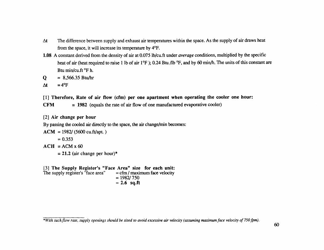
At The difference between supply and exhaust air temperatures within the space. As the supply of air draws heat
from the space, it will increase its temperature by 4*F.
1.08 A constant derived from the density of air at 0.075 lb/cu.ft under average conditions, multiplied by the specific
heat of air (heat required to raise 1 lb of air 1F ); 0.24 Btu /Ib *F, and by 60 min/h. The units of this constant are
Btu min/cu.ft *F h.
Q = 8,566.35 Btu/hr
At =4*F
[1] Therefore, Rate of air flow (cfm) per one apartment when operating the cooler one hour:
CFM = 1982 (equals the rate of air flow of one manufactured evaporative cooler)
[2] Air change per hour
By passing the cooled air directly to the space, the air change/min becomes:
ACM = 1982/ (5600 cu.ft/apt.)
= 0.353ACH =ACMx60
= 21.2 (air change per hour)*
[3] The Supply Register's "Face Area" size for each unit:The supply register's "face area" = cfm / maximum face velocity
= 1982/ 750= 2.6 sq.ft
*With suchflow rate, supply openings should be sized to avoid excessive air velocity (assuming maximum face velocity of 750fpm).60

C.2.3.2. Using Indirect Evaporative Cooler only [fig.24]
Final temperature and relative humidity = DBT= 87*F, and RH50%
BDT RH% WBT
A Outside conditions (day time) 97 35 75D After the cooling process through the heat exchange of the first stage 87 50 72
since Q=CFM x 1.08 x At
where Q = 8,566.35 Btu/hr
At = 8*F (explained in indirect cooling in 2-stage evaporative coolers)
[1] Therefore, Rate of air flow (cfm) per one apartment when operating the cooler one hour:
cfm = 991.4
[2] Air change per hour
If evaporative cooled air flows directly to the space,
the air change/minute becomes:
ACM = 991.4/(700x8 =5600 cu.ft per apt.)= 0.177
ACH =10.62
[3] The supply register's face area size for each unit:
= 991.4/ 750= 1.32 sq.ft
61
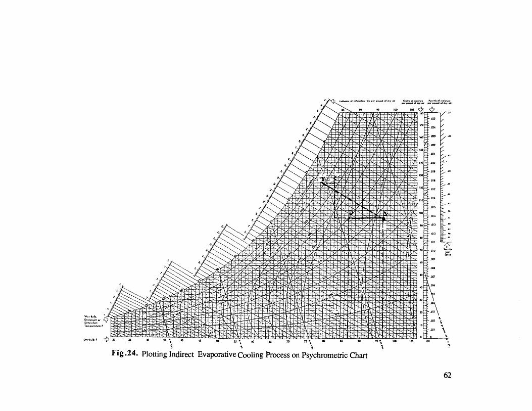
.. . ., c ... . . P..4. .4-
p-P - - Too, p 0 - 1 --
mso
- .0, .
- 130-
A I O
- - . 1
-110 -
15
3A3
-7 012 4 e
Jr70- o o,4- 9
-oi
s - - - -
- 01
62
C.2.4. Stack-Effect Ventilation by Means of the Solar Chimney System*
The evaporation process could be accomplished by the use of a fan's or a solar chimney's power of suction (stack
effect ventilation). Earlier in this chapter, we calculated how many evaporative coolers are needed for each apartment in
order to achieve a reasonable/comfortable temperatures and relative humidity inside the dwelling (RH 50%; T DB87*F in
case of indirect evaporative cooling, and RH 65%; TDB = 83*F in case of two stage evaporative coolers).
From these results, we have concluded that only one evaporative cooler for each apartment (with 1982 cfm) can cool
the dwellings. At night time the buildings' windows are opened to cross ventilation. Fans or solar chimney can be
used if there is no wind. However, the question remains whether we can use the solar chimney instead of the fan, and
what would be the suction power of either one. Will the sun bless us with this free power of cooling and moving air
into the dwellings? Is it feasible to operate the solar chimney at night to act as a fan and work by the laws of stack-effect
ventilation?
C.2.4.1. Design Decisions with Respect to Building Materials of the Solar Chimney
As explained before in chapter. 1, the solar chimney is basically a solar radiation trap, it acts like a solar heat collector.
Careful choice of surface material for this solar chimney is of prime importance, and that is in order to ensure best heat
absorption. Air (inside the solar chimney) is heated by convection, and indirectly by the emitted long wave solar
radiation from surrounding surfaces. Sol-air temperature** is a good indicator for heat absorption. Absorption of
different materials will be examined in the following section:
*Refer to chapter one for stack effect ventilation with solar chimney* *Sol-air temperature measures the combined effect of solar radiation and ambient air conditions of surfaces.
63
Sol-Air Temperature = outside temp.+ absorption of surface xSHGF*(transmission.88)wind coefficient of convection =3.0 BTU/h sq.ft
- back radiation loses to the sky vault x Emissivity of surfacewind coefficient of convection =3.0 BTU/h sq.ft
Concrete **has heat capacity of 29.4 BTU/cu.ft. When coated with a matt black paint its absorbance will be equal to
0.90 with high emissivity***; typically 90% [Johnson '81]..
Sol-air temperature For Black painted concrete surfaces = 97 +0.90x(280/0.88) - 15x0.90 = 187.95*F3 3
Shiny metals have low emissivity (absorption in the infra red); typically 10-15 % [Johnson '81].
Sol-air temperature For Galvanized steel = 97 + 0.25x(28010.88) - 15x0.25 = 121.75*F3 3
Selective surfaces are highly reflective surfaces treated chemically to combine low emissivity with their high
absorptivity. This treatment is based on the deposition of a very thin layer of a black metallic oxide over highly reflective
surfaces, or the deposition of successive very thin layers of reflecting and transparent materials. In this way, the
interference effect, which occurs between two reflective layers separated by a transparent layer of the proper thickness,
is utilized to reduce the emission of long-wave radiation without big reduction in solar absorption [Givoni '76]
*SHGF : is the solar heat gainfactor. [Ref. McGuiness I appendix]**Black painted concrete surfaces is the best affordable surface that can be selected to insure high air temperature inside the solar chimney. Airtemperature inside the solar collector ±5 F = 182 OF. In Egypt (April 1989) 1 m 3 of ordinary concrete costs 70 Egyptian pounds.***Absorption into the far infra-red. It is a measure of how easily radiation can escape from a surface [Johnson '81].
64

Sol-air temperature for Selective surfaces = 97 + 0.90 x (280/0.88') - 15x 0.25 = 191.2 0 F3 3
Sol-air temperature for tinted gray glass* = 97 + 0.30 x (280/0.88') - 15 x0.90 = 124 0 F3 3
Black painted Building Material (such as concrete ,or any other building material) are the best affordable surfaces that
can be selected to insure high air temperature inside the solar chimney. Air temperature inside the solar collector is no
greater than 182*F, and actually somewhat less due to the slight air movement through the voluminous sections of the
glass solar chimney.
C.2.4.2. Velocity of Air Inside the Duct Due to the Stack Effect (for fifth floor)
The air velocity (inside the duct) that is induced in a chimney due to the buoyancy forces is a function of its height and
difference in temperature of the outlet (where a solar collector can be used to elevate the air temperature), and the inlet
(the inside temperature of the house during day-time after the 2-stage evaporative cooler effect has taken place).
V = 9.4 4(h x At) = feet per minuteh = 35 .5 feet high for the fifth floor.At = (182 - 83) = 99*FV = 9 .4 4(35.5x 99)
= 557.26 ft/min.
C.2.4.3. The Duct Size of the Solar Chimney
Peak heat gain for one apartment equals 8566.35 Btu, and accordingly, the duct size could be determined by according
to the following formula:Peak heat gain = velocity of air in duct x area of duct x 1.08 x At [Johnson '88].8566.35 = 557.26 x area of duct x 1.08 x 4
Area of duct = 3.6 sq.ft For each apt.
*In Egypt (April 1989) 1 sq.m of 6mm tinted glass costs 50 Egyptian pounds. 65

C.2.4.4. Volume of Air Flow into the Solar Chimney for One Apartment (fifth floor)
Volume of air flow = velocity of air in duct x area of duct= 557.26 x 3.6= 2006 cfm
The evaporative cooler needed for cooling one apartment needs volume of air flow equals tol982 cfm/apartment, so
that the solar chimney can act like a fan needed for the evaporation process (only during the day).
At day-time Stack-effect ventilation is feasible. And hence, the question becomes how does the solar chimney operate,
and how can we heat the air inside the chimney at night.
The following is a summary of my previous trial calculations to store the heat from the sun at day time and release it at
night time. The storage of heat in water (for a 5-storey building) needs thousands of cubic feet of water to absorb
enough solar heat for the day. This is obviously not feasible in this application for the limitation of space availability on
the roof of the building. Storage of the solar heat in the thermal mass of the solar chimney, made with walls one foot
thick, will only operate for seven hours after sunset. However, if we can provide a heat source (low cost energy
source); such a common gas-Furnace appliance (which is relatively cheap in Egypt), we can supply this solar chimney
with the amount of heat that is equivalent to 1800 Btu/day, keeping its stack effect working during night time.
Average sensible heat gain at night = 81,088 Btu
Average sensible heat gain at night per hour for one apartment =1,689.25 Btu/h
The following procedure examines the capability of the gas-furnace (used to heat the air inside the solar chimney )to
remove average heat gain at night
Q = A x V (velocity of air in Solar chimney) x At2 x 1.08where V = 9.4 4(h x At )
h = height of solar chimney = 3 5.5 ft. for the fifth floor66

Assume that the gas furnace will produce heat that elevates the air temperature to 187*F ,while the air inside the house,
at night time, will have temperature of 874F.Ati = difference in temp. inside the solar chimney and inside the house = (187-87)*FV = 560 ft /minAt2 = difference in temp. inside and outside the house = (87-83 )*FA = area of the solar chimney duct = 3.6 sq.ftQ = 3.6 x (9.4 x 4(35.5x Ati)) x At2
= 8,468.25 Btu /h
The gas furnace succeeded in removing night heat gain from the dwelling.The second step is trying to
use the gas-furnace to assist the fans in further reduction to the air temperature.
Assume that the gas furnace will produce heat that elevates the air temperature (inside the solar chimney) to 400*F, while
the air inside the house, at night time, will have temperature of 87*F.
Q = A x V (velocity of air in Solar chimney) x At2 x 1.08AtI =400-87=313V =9.44(hxAti)V = 990.86 ft / min
Removed heat gain:
Q = 15,409 Btu/h
This gas furnace will remove night time heat gain, and will reduce the air temperature by 3.4*F and that will reduce the
cfm needed for the fans which in turn reduce the electricity consumption of the fans.
67

C.3 .SCHEME THREE
Examining whether the use of a thermal mass (cored concrete slab) flushed with night ventilation
can remove the average 12-hour heat gain at day time or not. Also, examining whether in case there
is no wind at night time, together with the use a night time forced ventilation method, in order to
flush the night time heat gain from the interior ceiling slab facing the space, or not.
In my observations; we can notice that scheme one failed to remove the twenty-four hour heat gain (closed and open
modes)*. However, we notice that this scheme one can easily remove the average heat gain at day time during when the
building is closed to the outside environment. At night, the building is open, and the night-time heat gain is
flushed away by forced ventilation (calculated in scheme two).
*when the column of air (inside the solar chimney) is heated by the sun, it rises to the outside of the chimney, and another column of coolerair replaces it. This air motion creates airflow inside the space.
68

C.4. SCHEME FOUR
Examining whether the use of a thermal mass (cored concrete slab) flushed with night ventilation
will remove the 12-hour heat gain at day time or not.
We use the night time forced ventilation method in order to flush the night time heat gain from the interior ceiling of
the slab facing the space (in case there is no wind at night time). We also use of the minimum power evaporative cooling
(2-stage & indirect evaporative coolers) during the day to remove the instantaneous peak heat accumulation.
C.4.1. Designing Decisions with Respect to Building Materials of the Solar ChimneyConcrete has heat capacity of 29.4 BTU/cu.ft, when coated with a matt black paint. Its absorbance will be equal to
0.90 with high emissivity (typically 90%).
Sol-air temperature for black painted concrete surfaces = 97 + 0.90x(280/0.88) - 15x0.90 = 187.95'F3 3
C.4.2. Velocity of Air inside the Duct Due to the Stack Effect (for fifth floor)V = 9.4 \(h x At) = feet per minuteh = 18 feet high for the fifth floor.At = (182 - 83)= 990FV = 9.4 (18 x 99)
= 396.8 ft/min.
C.4.3. The Duct Size of the Solar ChimneySince the night ventilation of the cored slab removes the average (sensible) heat gain at day-time, we need to remove the
instantaneous peak heat gain (sensible and latent).
The peak heat gain for one apartment = 8,566.35 Btu/h (1)
and the average heat gain removed by night forced ventilation = 6,978.325 Btu/h (2)
Therefore, the peak heat that should be removed each hour = (1) - (2) =1,588 Btu/h
Hence, the duct size would be determined according to the following formula:69

Hence, the duct size would be determined according to the following formula:
Peak heat gain to be removed = velocity of air in duct x area of duct x 1.08 x At1,588 = 396.8 x area of duct x 1.08 X 4Area of duct 0.9 sq.ft (for one apt.)
C.4.4. Volume of Air Flow into the Solar Chimney for One Apartment (fifth floor)
= velocity of air in duct x area of duct= 396.8 x 0.9
Volume of Air flow = 357 cfm
By passing the cooled air directly to space:
Air change/ min. = 357 / (5600 cu.ft/apt.) = 0.06Air change per hour = 3.9
C.5. Summary for Designing the System
C.5.1. SOLAR CHIMNEYFor Scheme-two:
- Duct size for each apartment- Velocity- Rate of air flow/unit (5th floor)- Height of solar chimney's
= 3.6 sq.ft= 557.26 ft/min.= 2006 (cfm: cubic feet of air per minute)=35.5 ft
C.5.2. EVAPORATIVE COOLER- rate of air flow in evap. cooler (in one tower at 5th floor) needed for cooling
- When using the in-direct evaporative cooler duct size for the cooling tower
-When using the 2-stage evaporative cooler duct size for the cooling tower
= 1854 cfm/apt.
= 1.3 sq.ft/one apt.
= 2.6 sq.ft/one apt.
70
C.5.3. SOLAR CHIMNEY For Scheme-four:
- Duct size for each apartment = 0.9 sq.ft
- Velocity = 398 ft/min.- Rate of air flow per unit (5th floor) = 367 (cfm: cubic feet of air per minute)- Height of solar chimney =18 ft
C.6. Evaluation of the Four Cooling Schemes
Scheme oneDid not succeed in removing the average 24- hour heat gain
Scheme threeSucceeded in removing the average 12-hour average heat gain at day time, but could not remove the heat in peak gain
conditions.
Scheme twoIdeal for retrofit (redesigning the existing apartment to be cooled passively and/or by low energy cooling). The
scheme relies on two sources of energy (electricity* at night and the power of the sun (at day time) that will drive the
stack-effect ventilation in the solar chimney). This scheme removes not only the average heat gain, but also peak heat
gain.
Some of the drawbacks of this scheme are the relatively big area of ducts that are used for the solar chimney system and
the cooling tower, as well as the big height of the solar chimney which rises two floors above the roof.
*These are fans that produce volumetric heat flow rate of 1000 cfm (cubic foot per minute); 700 sqft for each apartment,to remove the night
heat gain: In Egypt (April 1989) low energy fan (3000 cfm) costs about 40 Egyptian pounds, and one Kilo-watt per hour of electricity costs
0.05-0.07 Egyptian Pounds.
71

Scheme fourIdeal when used as a cooling solution integrated in the Architectural design of a new building. Just like scheme-two,
this scheme also relies on two sources of energy (electricity* at night and the power of the sun, at day time, that will
drive the stack-effect ventilation in the solar chimney), in order to remove not only the average heat gain, but also the
peak building heat gain. This scheme has many advantages:
The slab is relatively light in weight, and this in turn reduces the dead load that affects the size of the columns and
foundation. The cored slab ceiling can take many configurations in term of fabrication; it can be a pre-fabricated cored
slab; reinforced concrete slab with embedded air ducts; or hollow-block" ceiling with custom made blocks that have
the desired dimensions that corresponds to the slab cores calculated previously.
The biggest advantage of this scheme is the relatively small size ducts used for the solar chimney and the cooling
tower, as well as the small height of the solar chimney (rises only one floor above the roof) .The only drawback, from
my point of view, is the negative aesthetical effect this cooling scheme casts on the facade, especially the cored slab that
should have an opening to the outside environment.
*Fans that produces volumetric heat flow rate of 12,000 cfm (cubic foot per minute) 700 sq.ft for each apartment, to remove the night heat
gain, and another 1000 cfm [forced night time ventilation through the cored ceiling slab] to remove the day time average heat gain from each
apartment.**In Egypt (April '89) the price of 1 cu.mt of R.C. slab is 220-230 Egyptian Pounds, and 1 cu.mt of hollow blocks is 90 Egyptian Pounds
72

CHAPTER FOURDESIGN SYNTHESIS
A MULTI-STOREY BUILDING IN CAIRO/EGYPT
THE CONTEXT
Egypt is a highly over-urbanized country, where its entire population (54 million inhabitants) live on only 4% of the
land's area. The rest of the country is a barren arid desert. This over urbanization situation resulted in a severe housing
crisis formulated in two major dimensions [Beshara '81]: An enormous housing deficit; where 3.6 million household
units should be built between 1981 and 2000 [Molt '80]. Affordability; where the enormous gap between the cost of
housing supplied and the ability of the majority of housing demand group to pay is growing.
To face this sharp, political and economical, problem the government started adopting Industrialized building systems
techniques as a means of providing mass numbers of housing units. While modular coordination and standardization
were practically the major guiding lines for designing those "industrialized" building, unfortunately, environmental
considerations were never accounted for. Accordingly, this thesis stresses the effects and impacts of those
environmental issues. In this chapter, the technical analysis for the two previously selected schemes is formulated as
architectural design sketches.
The chosen housing type for both schemes [found out to be widely used in and around Cairo [Cairo University &
MIT '79], is a traditional 5-storey walk-up building with a core stair case that serves four apartments per floor. Both
schemes are designed to operate independently, regardless of orientation.
For the redesign of this building type, Internal Flexibility shall be stressed upon for the given architectural plan:
The possibility of having different configurations for a floor plan, where areas of each unit may vary, will be a guiding
theme, together with the quantitative criteria for passive cooling system design. This particular criteria has an impact on
73

the interior, as well as, the exterior of the building (as we shall see in the provided drawings). It can always result in a
continuous FORM change and generation processes.
Note that the forth-coming illustrations and sketches for scheme four (application of this cooling system to new
building) are in figures 25 to 43. Figures 44 to 45 are for scheme two (application of cooling system to redesigned
existing building).
74

Scheme Four (for new building)This is characterized by a general internal flow configuration of a building ventilated and cooled at day time by means
of the solar atrium chimney system. Illustrated are the cooling tower, the insulated cold air shaft, the conditioned interior
space, and the solar atrium chimney.
The solar chimney comprises an east and west facing solar air heaters and insulated hot air shaft The solar air heaters
are rectangular in plan with their long sides facing east and west. The cooling appliance (evaporative coolers) cools the
incoming air below the outside air temperature, which in turn causes the air being cooled to fall. The pressure
differential created in the cold shaft is called "theoretical draft" [Haisley '81], as in the case of the solar chimney. At
night time, forced ventilation is used through cored concrete slabs.
75

Scheme Four
Duct has two openings: to the west and east parts of the
main duct connecting two chimneyssolar Atrium chimney
Insulated cooling
5'atdion A -A
Day and night operation are completely separated; which means that the ventilation of coredslab at night time will not play any role in the cooling system at day time. This decision ofseparating the two operations was made because of the unpredicted level of relativehumidity that could damage the plastering, and could also be responsible of Mildew or wetspots on the ceiling if it exceeds the average percentage (refer to chapter three fordescription of this scheme).
Fig.25. Scheme Four achieved by the solar Atrium chimney which pulls the air by suction forces
76

in order to achieve the best cross ventilation throughout the whole apartment, air can be pulled
through the duct to the solar chimney. AT- I+"."j"7
tinted glasssolar Atrium chimney
I ;ll " Illllllllllliiiiilllo I
Fig.26. Day-time Operation (for better cross ventilation)
I I
Insulated cooling
tower
77

Scheme Four
Duct has two openings: to the west andeast parts of the Solar Atrium Chimney
night forced air ch
through the ceiling
Air is permitted through
the building skin.
- optional: air is induced at night by stack effect ventilation
where air is warmed by means of a gas-furnace
Fig.27. Night-time Operation (opened mode)showing optional solution
78
Design building's elements that act like cooling devicessuch as:Cored concrete slabwall openingsCooling towerSolar chimney
79

itms
insulation to promote minimum loss of coolth
Air ducts could be "formed" of galvanized steel sheets
Fig.28. Cored Concrete Slab (used as one of the cooling devices)
80
Design of building's elements
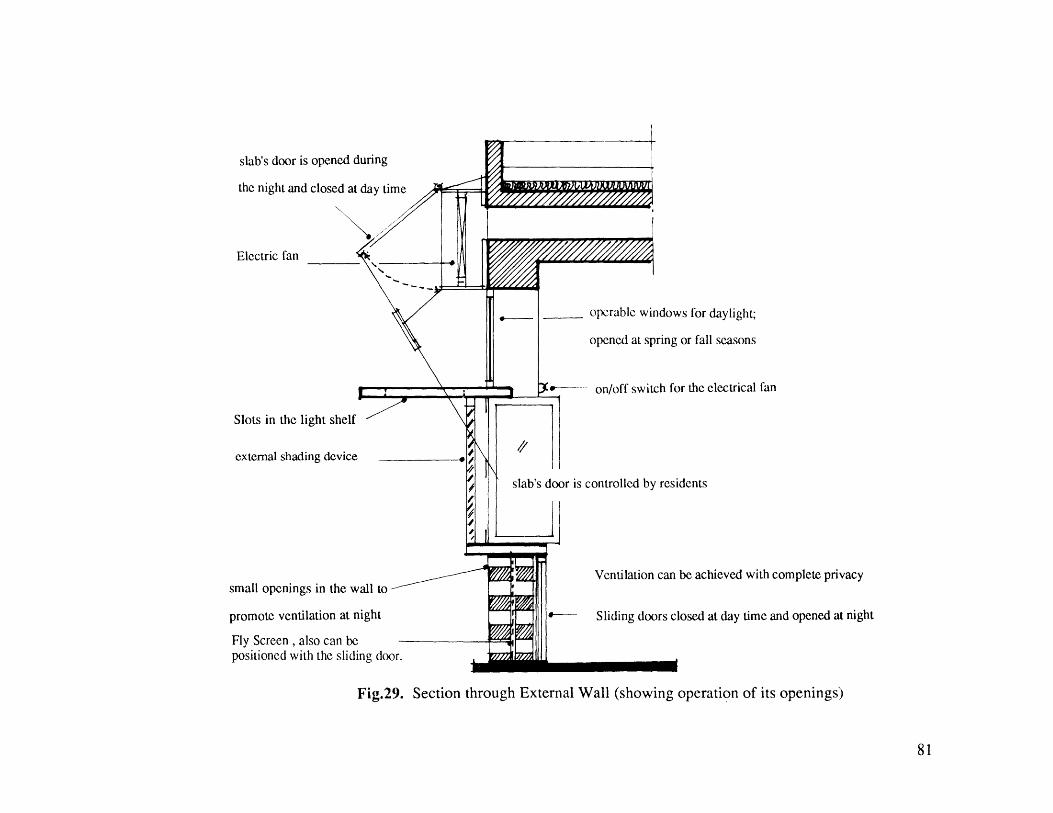
slab's door is opened during
the night and closed at day time
Electric fan
Slots in the light shelf
external shading device
small openings in the wall to
promote ventilation at night
Fly Screen , also can bepositioned with the sliding door.
operable windows for daylight;
opened at spring or fall seasonsK on/off switch for the electrical fan
slab's door is controlled by residents
Ventilation can be achieved with complete privacy
Sliding doors closed at day time and opened at night
Fig.29. Section through External Wall (showing operation of its openings)
81

Light shelf to reflect the direct and diffused sunlight.and this increases the *intensity of daylight entering the dwelling and I Night forced ventilation through ceiling
openmngsminimizes the use of artificial light.
window for view, with sliding external shading device -. -
Night Ventilation through wall openings -in order to promote ventilation at "bed" level/. -.' wing walls to increase the effectiveness
of the wind entering the dwellings (Watson '83)
Fig .30 . Window Design
Windows' function is to promote daylight, view, and ventilation. Here, for these three functions of thewindow, there are three different openings
82
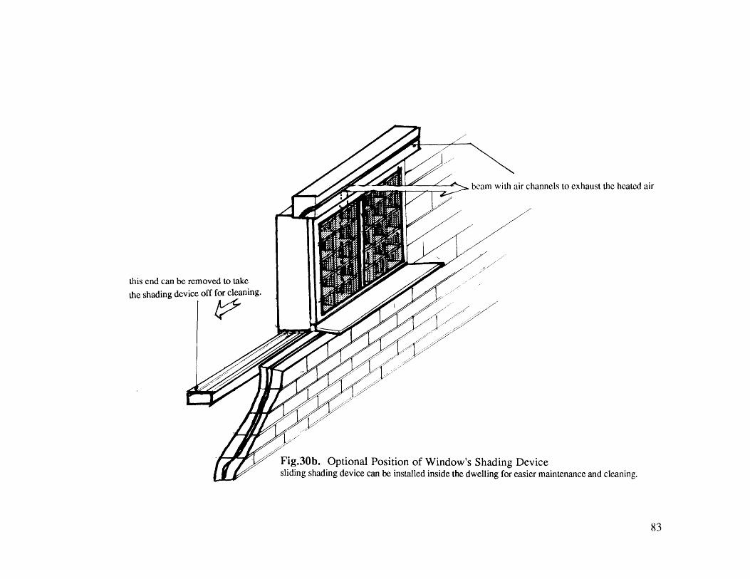
this end can be removed to take
the shading device off for cleaning.
channels to exhaust the heated air
Fig.30b. Optional Position of Window's Shading Devicesliding shading device can be installed inside the dwelling for easier maintenance and cleaning.
83

Designing the cooling tower:As an introduction the two - stage evaporative coolingprocess, and different types of heat exchangers will be explained.
84

Fresh Air
fresh Air direct Evaporation ' Heat Exchanger air / waterfresh Airair /' water
Cool
Dry Air
Dire.ct Evaporation
Cold Air
Fig . 31. Diagrams of Two-Stage Evaporative Cooler
Heat Exchanges
[1] Air to Air Heat Exchanger[2] Air to Water Heat Exchanger-[3] Water to Water Heat Exchanger
85
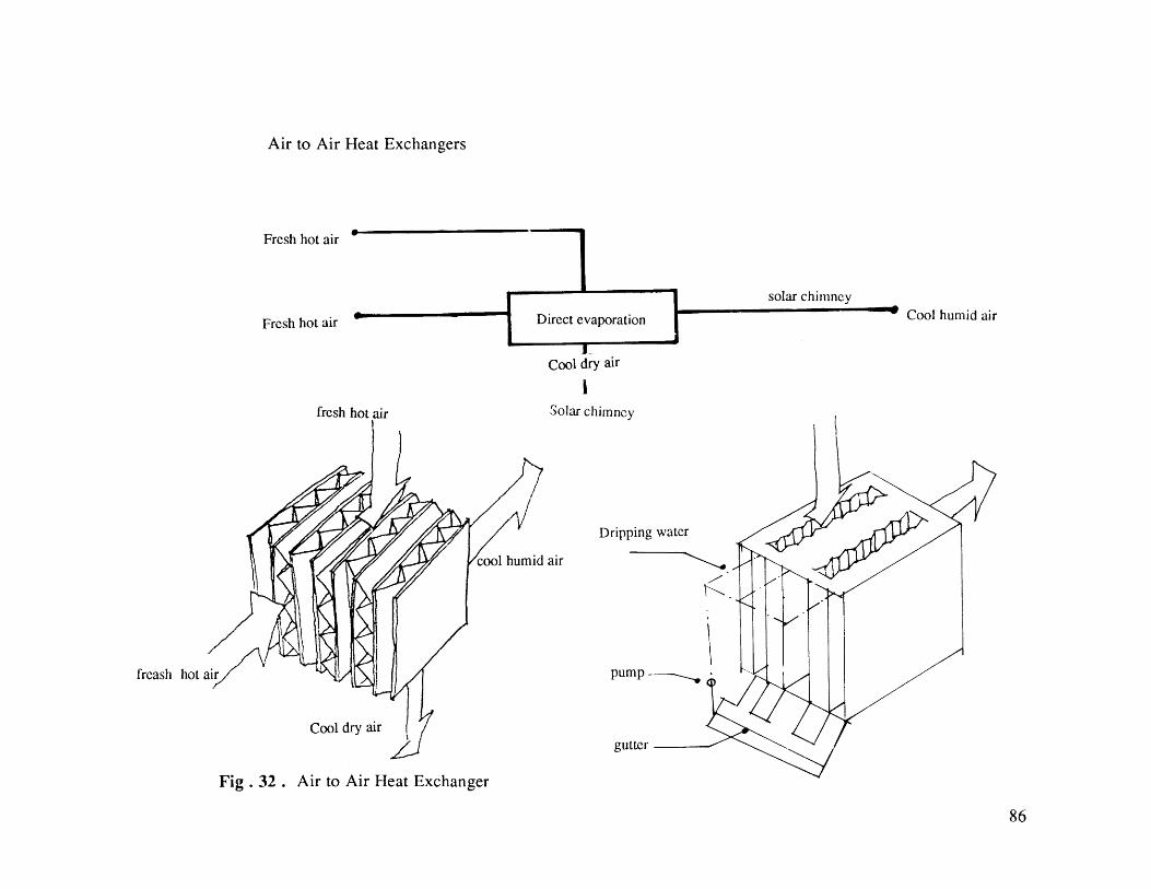
Air to Air Heat Exchangers
Fresh hot air -
Fresh hot air a-
fresh hot air
solar chimney
Cool humid air
Cool dry air
ISolar chimney
Dripping water
humid air
pumpfreash hot
Cool dry airgutter
Fig . 32 . Air to Air Heat Exchanger
86
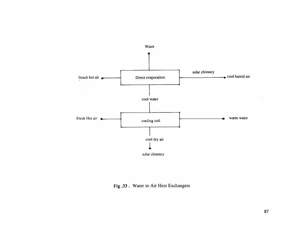
Water
solar chimney
freash hot air cool humid air
cool water
Fresh Hot air warm water
cool dry air
Isolar chimney
Fig .33 . Water to Air Heat Exchangers
87

Final design of the cooling tower using two types of " Heat Exchangers".
88
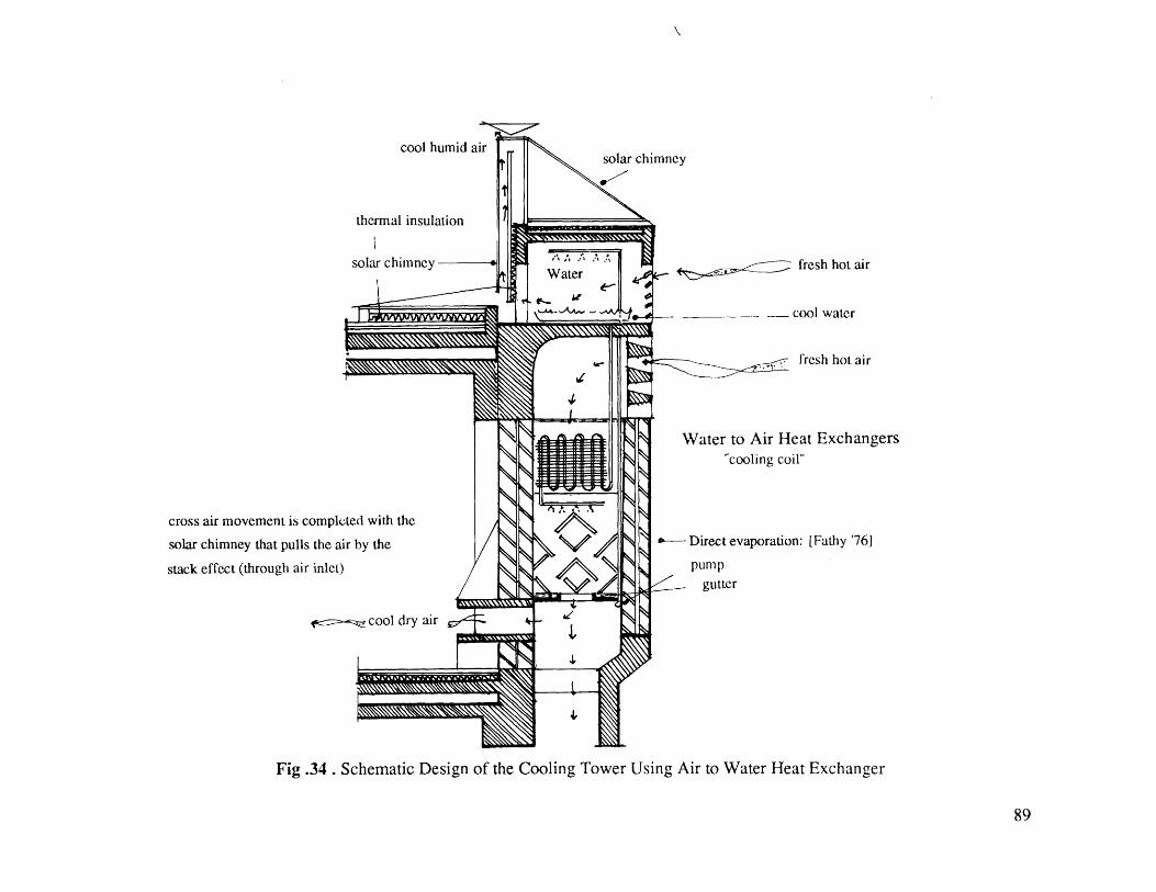
cool humid air
thermal insulation
solar chimney
cross air movement is completed with the
solar chimney that pulls the air by the
stack effect (through air inlet)
cool dry air
solar chimney
AZ fresh hot air
cool water
fresh hot air
Water to Air Heat Exchangerscooling coil"
Direct evaporation: [Fathy '76]
pump
gutter
Fig .34 . Schematic Design of the Cooling Tower Using Air to Water Heat Exchanger
89
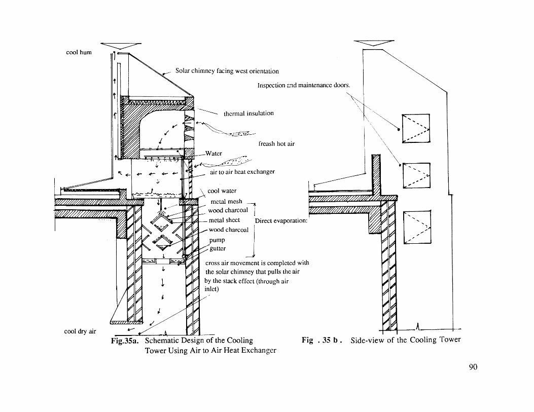
Solar chimney facing west orientation
Inspecti
thermal insulation
freash h
Water
- _air to air heat exchanger
cool water
metal meshwood charcoal
metal sheet
on and maintenance doors.
ot air
)irect evaporation:wood charcoal
pumpgutter
cross air movement is completed with
the solar chimney that pulls the air
by the stack effect (through airinlet)
Fig.35a. Schematic Design of the CoolingTower Using Air to Air Heat Exchanger
Fig . 35 b . Side-view of the Cooling Tower
cool hum
cool dry air
90

Design of solar chimney risers for the atrium court.
91
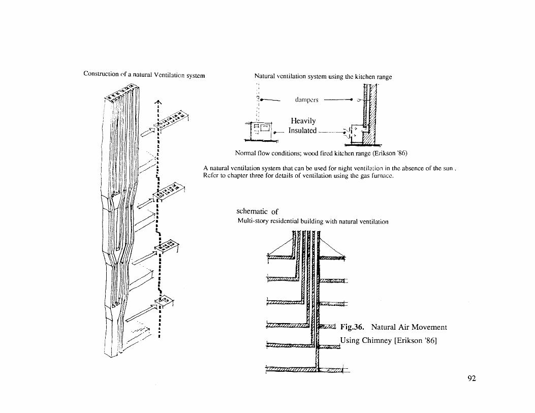
Construction of a natural Ventilation system
e---- dampers
1, HeavilyInsulated
Normal flow conditions; wood fired kitchen range (Er-ikson '86)
A natural ventilation system that can be used for night ventilation in the absence of the sunRefer to chapter three for details of ventilation using the gas furnace.
schematic ofMulti-story residential building with natural ventilation
Pt-z Fig.36. Natural Air Movement
_____Using Chimney [Erikson '86]
92
Natural ventilation system using the kitchen range
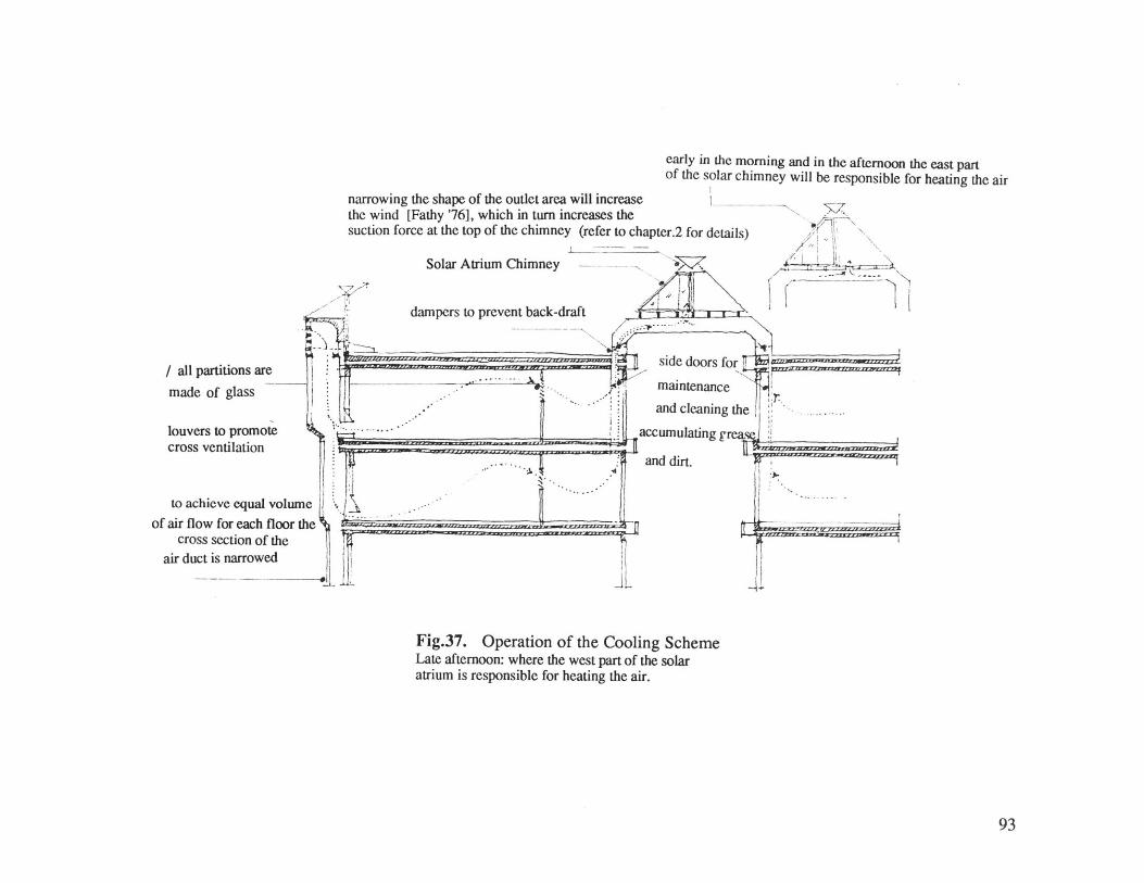
early in the morning and in the afternoon the east partof the solar chimney will be responsible for heating the air
narrowing the shape of the outlet area will increasethe wind [Fathy '76], which in turn increases thesuction force at the top of the chimney (refer to chapter.2 for details)
Solar Atrium Chimney
dampers to prevent back-draft A ./
-----V
/all partitions are
made of glass
louvers to promotecross ventilation
to achieve equal volume
of air flow for each floor thecross section of the
air duct is narrowed
Fig.37. Operation of the Cooling SchemeLate afternoon: where the west part of the solaratrium is responsible for heating the air.
93
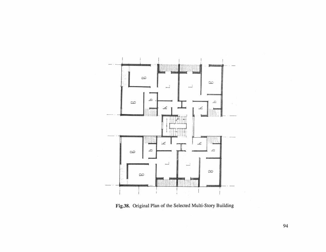
~*'. J ii Bill
Li
Fig.38. Original Plan of the Selected Multi-Story Building
94

Fig .39. Plan(Cairo University
Alternative Design after Applying "SAR Method"& MIT, 1978)
95
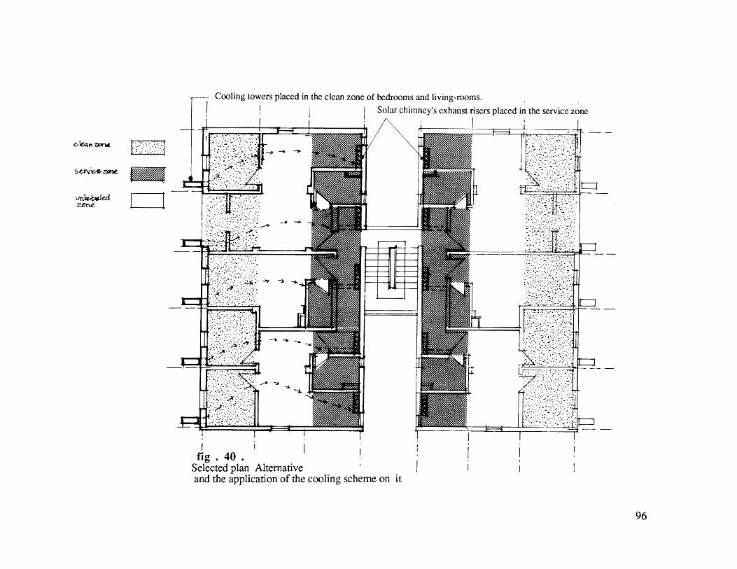
zone
Cooling towers placed in the clean zone of bedrooms and living-rooms.Solar chimney's exhaust risers placed in the service zone
fig. 40Selected plan Alternativeand the application of the cooling scheme on it
96

North east-east to south west-west is the bestorientation for buildings in Cairo /Egypt(Fathy 1976.]
night fGoced air channels through L
Fig.41. The Roof Layout
97
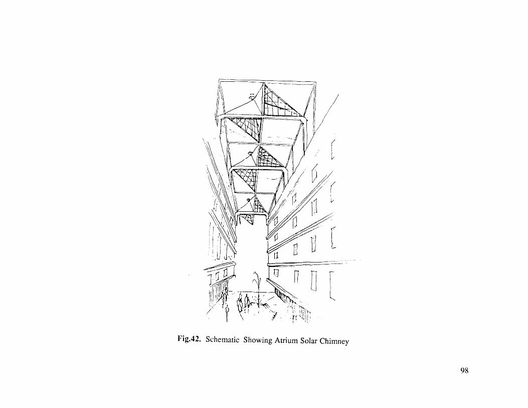
Fig.42. Schematic Showing Atrium Solar Chimney
98

Fig.43 a.Elevation of scheme 4 99
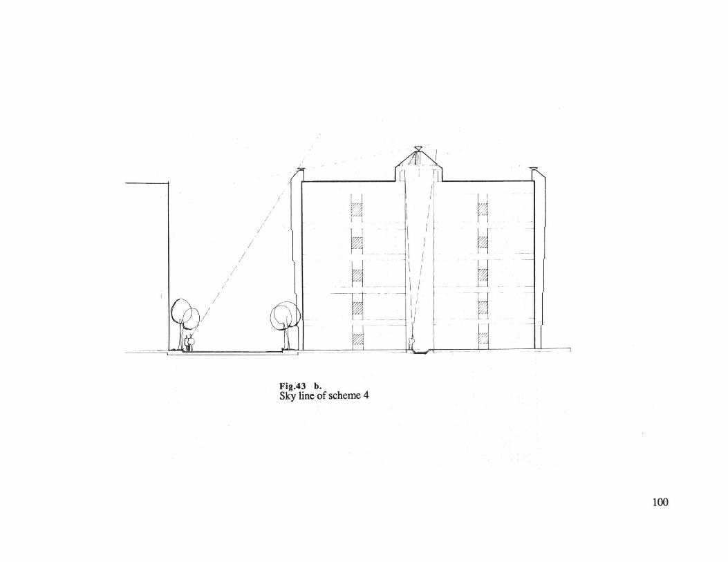
VA
Vr4
Fig.43 b.Sky line of scheme 4
100

Architectural Design
Scheme TwoThis is characterized by a general internal flow configuration of a building ventilated and cooled at day time by means
of the solar chimney system. Illustrated are the cooling appliance, the insulated air shaft, the conditioned air space and
the solar chimney.
The solar chimney comprises an east and west facing solar air heaters and insulated hot air shaft. The solar air heaters
are rectangular in plan with their long sides facing east and west. The cooling appliance (evaporative coolers) cools the
incoming air below the outside air temperature, which in turn causes the air being cooled to fall. The pressure
differential created in the cold shaft is called "theoretical draft" [Haisley '81], as in the case of the solar chimney. At
night time, forced ventilation is used for ordinary concrete slabs.
101
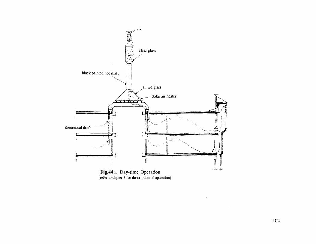
clear glass
black painted hot shaft
tinted glass
_- Solar air heater
theoretical draft
Fig.44a. Day-time Operation(refer to chpter.3 for description of operation)
102

zone
Cooling towers placed in the clean zone of bedrooms and living-rooms.
Solar chimney's exhaust risers placed in the service zone
Fig.44 b.Retrofitting the original planand positioning the cooling system.
103

~4II~
Fig.45. Skyline of Scheme 2
104
CONCLUSION
This research analytically concludes that: scheme one which uses the thermal mass -cored concrete slab-
flushed with night ventilation, failed to remove the average twenty-four hour heat gain . Scheme three, which
uses the thermal mass -cored concrete slab flushed with forced night ventilation, succeeded in removing average
twelve-hour heat gain at day time, and natural night time ventilation through the windows to remove night time heat
gain. The third scheme, however, failed to remove the hourly peak heat gain at day time. On the other hand,
scheme two, which uses evaporative cooling by means of a solar chimney system at day time, and forced night
ventilation for the ordinary slab at night time, together with schemefour which uses the night time forced
ventilation of the cored concrete slab and minimum use of evaporative cooling by means of a solar chimney system
at day time, both succeeded in removing the peak heat gains.
In the qualitative Architectural study, schemes two andfour (and their cooling systems) are expressed as
physical architectural elements: Cooling tower, Solar atrium chimney, ceiling ducts, and wall openings. Both
schemes use the court space without blocking the wind or daylight into the rooms overlooking that court. Also, both
schemes are orientation-free which means that they can be applied to any building with any design, independent of
orientation, as long as the cooling tower and solar chimney are placed properly following the previously explained
zones (clean and service zones -chapter.4).
Schemes four and two are designed for the middle-class Egyptian context with respect to its economical and social
constrains. This design uses indigenous materials and local building systems. Also, this design gives preference to
ventilation-cooling systems. that achieves privacy as a contextual social value.
In fact, both schemes (two and four) did not only attain desired reduction of the interior's dry bulb temperature,
but also maintained comfortable levels of relative humidity. The schemes succeeded in; 1) promoting air movement
inside the dwellings (by the use of solar chimney system), 2) reducing the consumption of artificial lighting (by the
105

careful design of windows and shading devices), 3) and using only six hours of low energy fans at night time
(12,000 cfm per 81 sq.m).
Scheme two is recommended for new buildings; because its cooling system elements integrate well with the
buildings' architectural design. The solar Atrium chimney is an attractive architectural element that can create a
pleasant interior court-yard for common activity and urban public use. On the other hand, scheme four is
recommended for retrofitting existing building.
In the end, this research throws light on ways for adapting low energy cooling systems for buildings in hot arid
climates. It certainly raises questions and and leaves the research door open for further development. It also
confronts the architectural community with means of providing thermal comfort dwellings while remaining within
the contextual domain of design and architecture.
106

This section is a continuation of Peak heat gain calculations (started in chapter three)
A.1. Peak Heat Gain for the EXISTING BuildingExternal Walls (ONE floor per ONE hour) Q = A x U x CLTDcorrected
Orien- A U CLTD correction CLTDcort'd Qtation LM K Tin Tout
Northern edge of the buildingNE 297 0.36 21 1 1 -5 -1 15 1603.8SW 286 0.36 28 -1 1 -5 -1 21 2162.16SE 479 0.36 26 -1 1 -5 -1 19 3276.36NW 506 0.36 23 1 1 -5 -1 18 3278.8Southern edge of the buildingNE 297 0.36 21 1 1 -5 -1 15 1603.8SW 286 0.36 28 -1 1 -5 -1 21 2162.16SE 506 0.36 26 -1 1 -5 -1 19 3461.04NW 479 0.36 23 1 1 -5 -1 18 3103.92
Total Heat Gain 20,652 Btu/hr
A Floor area (4 apartments) sq.ftU Overall coefficient of heat transmission Btu/sq.ft 'F h.CLTD Maximum Cooling load temperature difference for sun lit walls (conventional units) [McGuiness & Stein '86].
For group wall B: 8" common brick (weight 130 lbs/sq ft)CLTDcorrection: cooling load temperatures' difference in existing building (Cairo 320N latitude in July).LM: The latitude-month correction for latitude 32*N in July at 14:00 hours.K: is the color adjustment factor and is applied after making latitude-month adjustments.Tin: (78-TR) indoor design temperature correction, where TR=indoor temperature (TR=83).Tout: (To-85) outdoor design temperature correction, where To=average outside temperature on design day.To=97*F - (daily range (26'F))/2. Therefore, To=84 and Tout-(84-85)= -1
A.2. Peak Heat Gain after REDESIGNING the Building
107
APPENDIX .A.

External Walls (ONE floor per ONE hour)
Orien- A U CLTD correction CLTDcort'd Qtation LM K Tin Tout
Northern edge of the buildingNE 297 0.19 21 1 1 -5 -1 15 846.45SW 286 0.19 28 -1 1 -5 -1 21 1141.1SE 479 0.19 26 -1 1 -5 -1 19 729.1NW 506 0.19 23 1 1 -5 -1 18 1730.52Southern edge of the buildingNE 297 0.19 21 1 1 -5 -1 15 846.45SW 286 0.19 28 -1 1 -5 -1 21 1141.1SE 506 0.19 26 -1 1 -5 -1 19 1826.6NW 479 0.19 23 1 1 -5 -1 18 1638.18
Total Heat Gain 10,917.5Btu/hr
108
Q = A x U x CLTDcorrected
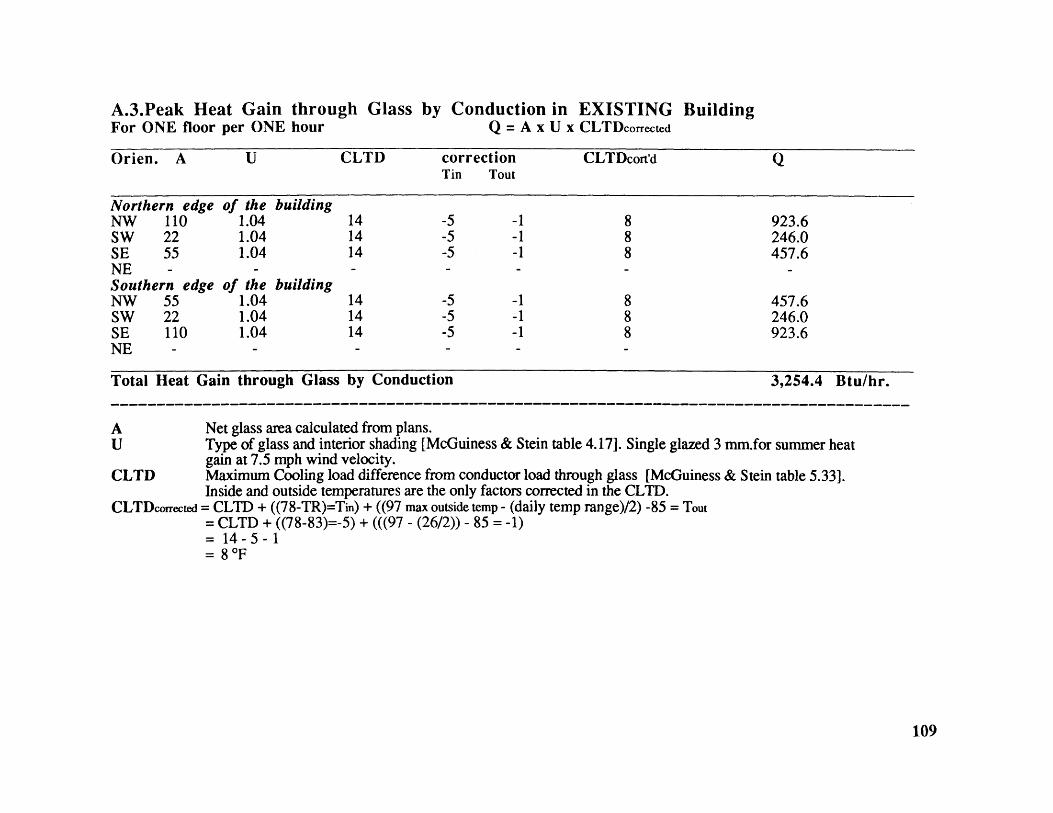
A.3.Peak Heat Gain through GlassFor ONE floor per ONE hour
by ConductionQ = A x
in EXISTINGU x CLTDcorrected
Orien. A U CLTD correction CLTDcort'd QTin Tout
Northern edge of the buildingNW 110 1.04 14 -5 -1 8 923.6SW 22 1.04 14 -5 -1 8 246.0SE 55 1.04 14 -5 -1 8 457.6NE - - - - -
Southern edge of the buildingNW 55 1.04 14 -5 -1 8 457.6SW 22 1.04 14 -5 -1 8 246.0SE 110 1.04 14 -5 -1 8 923.6NE - - - - -
Total Heat Gain through Glass by Conduction 3,254.4 Btu/hr.
A - - - - - - - - - - - - - - - - - - - - - - - - - - - - - - - - - - - - - - - - - - -
AU
CLTD
CLTDcorrected
Net glass area calculated from plans.Type of glass and interior shading [McGuiness & Stein table 4.171. Single glazed 3 mm.for summer heatgain at 7.5 mph wind velocity.Maximum Cooling load difference from conductor load through glass [McGuiness & Stein table 5.33].Inside and outside temperatures are the only factors corrected in the CLTD.
= CLTD + ((78-TR)=Tin) + ((97 max outside temp - (daily temp range)/2) -85 = Tout= CLTD + ((78-83)=-5) + (((97 - (26/2)) - 85 = -1)= 14-5-1= 8 'F
Building
109

A.4. Peak Heat Gain through GlassFor ONE floor per ONE hour
by Conduction after REDESIGNINGQ = A x U x CLTDcorrected
the Building
Orien. A U CLTD correction CLTDcort'd QTin Tout
Northern Edge of the buildingNW 110 1.04 14 -5 -1 8 923.6SW 22 1.04 14 -5 -1 8 246.0SE 55 1.04 14 -5 -1 8 457.6NE 11 1.04 14 - - 8 91.4Southern edge of the buildingNW 55 1.04 14 -5 -1 8 457.6SW 22 1.04 14 -5 -1 8 246.0SE 110 1.04 14 -5 -1 8 923.6NE 11 1.04 14 - - 8 91.4
Total Heat Gain Through Glass by Conduction 3437.2 Btu/hr.
110

APPENDIX .B.
In this section, Average heat gains will be calculated to be used later when applying cooling systems.
B.1. Heat Gains per Hour after REDESIGNING theExternal Roof (One Floor per ONE Hour)
BuildingQ = AxUxCLTD(average corrected)
A U CLTD correction CLTDcort'd QLM K Tin Tout F
2800 0.0 7 49 1 0.5 -5 -1 1 19,5 3,822
heat gain for roof /24 h =U x A x CLTDaverage x 24 = 91,728 BTU/dayheat gain for roof /12 h =Ux A x CLTDaverage x 12 = 45,864 BTU/12h
B.2. Average Heat Gain after REDESIGNING the BuildingExternal Walls for One floor per One hour Q = AxUxCLTDaverage corrected
Orien. A U CLTD correction CLTDcort'd QLM K Tin Tout
Northern edge of the buildingNE 297 0.19 17 1 1 -5 -1 12 672SW 286 0.19 21 -1 1 -5 -1 14 720SE 479 0.19 20 -1 1 -5 -1 13 1175.23NW 506 0.19 17 1 1 -5 -1 12 1160.5Southern edge of the buildingNE 297 0.19 17 1 1 -5 -1 12 672.54SW 286 0.19 21 -1 1 -5 -1 14 760.76SE 506 0.19 20 -1 1 -5 -1 13 1241.9NW 479 0.19 17 1 1 -5 -1 12 1092.12
111
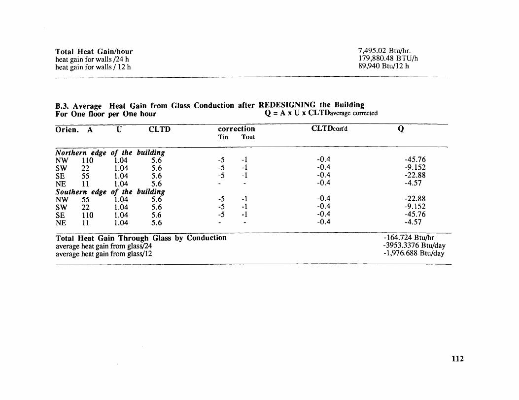
Total Heat Gain/hourheat gain for walls /24 hheat gain for walls / 12 h
7,495.02 Btu/hr.179,880.48 BTU/h89,940 Btu/12 h
B.3. Average Heat Gain from Glass Conduction after REDESIGNING the BuildingFor One floor per One hour Q = A x U x CLTDaverage corrected
Orien. A U CLTD correction CLTDcort'd QTin Tout
Northern edge of the buildingNW 110 1.04 5.6 -5 -1 -0.4 -45.76SW 22 1.04 5.6 -5 -1 -0.4 -9.152SE 55 1.04 5.6 -5 -1 -0.4 -22.88NE 11 1.04 5.6 - - -0.4 -4.57Southern edge of the buildingNW 55 1.04 5.6 -5 -1 -0.4 -22.88SW 22 1.04 5.6 -5 -1 -0.4 -9.152SE 110 1.04 5.6 -5 -1 -0.4 -45.76NE 11 1.04 5.6 - - -0.4 -4.57
Total Heat Gain Through Glass by Conduction -164.724 Btu/hraverage heat gain from glass/24 -3953.3376 Btu/dayaverage heat gain from glass/12 -1,976.688 Btu/day
112

B.4. Average Heat Gain through Glass by SolarFor One floor all day
Orien. A
Northern edge of the buildingNW 110SW 22SE 55NE 11Southern edge of the buildingNW 55SWSENE
2211011
SHGF
945865855884
945865855884
Radiation after the REDESIGNQ = A x SHGFaverage/all day x SC
Sc
0.250.250.25
0.25
0.250.250.250.25
Q
25,987.54,757.51,756.252,431.00
12,993.754,757.523,512.52,431.0
Heat Gain through Glass by Solar RadiationTotal Heat Gain through Glass (Rad. & cond.)
88,627.0 Btu/hr.86,651.0 Btu/hr
B.5. Average Heat Gain from PEOPLE (sensible) Q = number of people/one floor x heat gain x CLF
no. of people CLF heat gain/person Q
Sensible Heat 20 0.92 225 4,140
Total Heat Gain from people/h 4,140
113
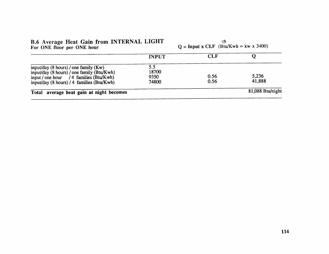
B.6 Average Heat Gain from INTERNAL LIGHTFor ONE floor per ONE hour Q = Input x CLF (Btu/Kwh = kw x 3400)
INPUT CLF Q
input/day (8 hours) / one family (Kw) 5.5input/day (8 hours) / one family (Btu/Kwh) 18700input / one hour / 4 families (Btu/Kwh) 9350 0.56 5,236input/day (8 hours) / 4 families (Btu/Kwh) 74800 0.56 41,888
Total average heat gain at night becomes 81,088 Btu/night
114

APPENDIX c.
SCHEME TWO
Using the Night-time forced Ventilation; to flush the night time heat gain from the ordinary uncored ceilingslab with the Evaporative Cooling* during the day (in order to remove instantaneous heat accumulation).
Mass surface areaMass heat capacity = vol. of concrete x 22.5
= 2800 sq.ft= 188, 900 Btu/F
Hour ' Cooling Mass Temperature
21 83.55 none = 83.5522 82.2 lx(83.55-82.20) x 2800 = 3780 83.55 -(3780/188900) = 83.3523 80.85 lx(83.35-80.85) x 2800 = 7000 83.35 -(7000/188900) = 82.9724 79.50 lx(82.97-79.50) x 2800 = 9716 82.97 -(9716/188900) = 82.451 78.15 lx(82.45-78.15) x 2800 = 12056.59 = 82.332 76.80 lx(82.33-76.80) x 2800 = 15489.84 = 81.503 75.40 lx(81.50-75.40) x 2800 = 17109.2 = 80.594 76.00 lx(80.59-76.00) x 2800 = 12865.3 = 79.905 78.40 lx(79.90-78.40) x 2800 = 4226 = 79.67
Cooling Btu = 114,714.9
Supplementary cooling = (83.55-79.67)X (2.25 )X floor area (2800/2.7)= 9,053.01 Btu/night
Total Cooling at Night = 123,767 Btu/nightApproximate flow required for night ventilating air = cfm
CFM =12,541 cu.ft/ min/ one apartmentsACM =12,541/ 5600
Cooling the ordinary slab by Forced night ventilation succeeded in removing the heat gain at night.
115
APPENDIX .D.
Thermal Effect of Windows and Efficiency of Shading DevicesThe thermal effect of windows is dependent on the shading provided and the properties of its glass*. The thermal effect of the
glass can be, furthermore, considered from two aspects: First, the actual heat gain (from the glass) of the interior, which isimportant for calculating the cooling loads; and second, the resulting rise in the indoor temperature which have a great effect onindoor thermal comfort.
Shading this glass affects the quantity of incident radiation and accordingly modifies both the heat flow to the interior. Also, thequantitative modification of this incident radiation depends on the location of the shading with respect to the glass (whetherinternal or external), the orientation of the window, the shape, color, and depth of the shading device.
From a study done by Givoni [Givoni 76]; it was concluded that for latitude 32*N** the adequate shading for east and westorientations can be provided with an egg-crate shading, especially if the vertical members are oblique at a 450 angle to thesouth (with the shades projecting over the window 2/3 of its length). Horizontal shading, however, is more effective thanvertical shading, even with infinite height. That's because it provides very poor shading in the summer, while cutting off almostall radiations in winter. For southern, southwest orientations horizontal shadings (with the shades projecting over thewindow 1/3 of its length) are more effective than vertical ones, while the egg-crate frame shape is the most effective.
In another study done by Shaviv [Shaviv 88]; he continued exploring the optimum external shading device with the use of acomputer program "SUNSHADES" (developed by Shaviv). According to the method suggested, a shading nomogram, with allthe possible solutions for external sunshades, is first generated by the computer, and then the design of sunshades can becarried out by the architect following this nomogram ***.
The "ENERGY" simulation model was used to evaluate four different types of geometric forms for the external shadingdevices. For each geometric solution different depth of shading devices were examined. For the southeast orientation, thestudy concluded that the diagonal external shading device was the best. A comparison between different shading devices ****was also conducted for the south-east and the north-west orientations. It was found that the best shading device (with lowestenergy consumption for cooling, heating, and for lighting ) was the external shading device for the south east orientation.Also, venetian blinds and white curtains were found to be the best shading devices for the northwest orientation.
*In Egypt the cost of tinted "Low E" or "reflecting" glass is too high, therefore, single glass 3mm. will be used, and a better external shading devicewith high percentage of shading coefficient will be examined and then applied in the design.**Very close to Cairo Latitude 30'N*** The nomogram gives the minimum length of the pole in each grid point of the given window that will cast a shadow long enough to reach thebottom of the window or its sides. The test is carried over the whole period during which the window should be protected (months and hours). The neededprotection period and hours are determined according to the amount of short wave radiation (direct and defuse) incident on a particular window, and thehours the building is in use. The nomogram can be used to determine the kind of external shading devices solution that is needed [Givoni 19781.****This comparison was held between Venetian blinds, white curtains, and external shading devices.
116
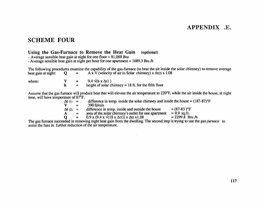
APPENDIX .E.
SCHEME FOUR
Using the Gas-Furnace to Remove the Heat Gain (optional)- Average sensible heat gain at night for one floor = 81,088 Btu- Average sensible heat gain at night per hour for one apartment = 1689.3 Btu /h
The following procedures examine the capability of the gas-furnace (to heat the air inside the solar chimney) to remove averageheat gain at night: Q = A x V (velocity of air in Solar chimney) x At(2) x 1.08
where: Vh
= 9.4 4(h x Atl )= height of solar chimney = 18 ft. for the fifth floor
Assume that the gas furnace will produce heat that will elevate the air temperature to 220*F, while the air inside the house, at nighttime, will have temperature of 87F.
At (1) = difference in temp. inside the solar chimney and inside the house = (187-87)*FV = 390 ft/minAt (2) = difference in temp. inside and outside the house = (87-83 )*FA = area of the solar chimney's outlet for one apartment = 0.9 sq.ft.Q = 0.9 x (9.4 x 4(18 x Ati)) x At2 x1.08 = 2299.8 Btu /h
The gas furnace succeeded in removing night heat gain from the dwelling. The second step is trying to use the gas-furassist the fans in further reduction of the air temperature.
nace to
117

CAIRO IAP UNITED ARAB REPUBLIC/EGYPT
LAT 30 08N LONG 31 24E ELEV 367 FT APPENDIX .F.MEAN FREQUENCY OF OCCURRENCE OF DRY BULB TEMPERATURE (DEGREES F) WITH MEAN COINCIDENT WET BULB TEMPERATURE (DEGREES F) FOR EACH DRY BULB TEMPERATURE RANGE
MAY
Tempera Obsn Total N
ture Hour Op Obsn C
Range 01 09 IT
10 to to B
08 16 24
110/ 114105/109
100/10495/9990/9485/8980/84
75/7970/7465/6960/6455/59
110/114105/109
100/10495/9990/9485/8980/84
75/7970/7465/6960/6455/59
50/ 5445/4940/4435/39
136
134392819
519335056
55227
0 1
1 66 25
16 5027 8045 107
57 12552 11737 1367 88
9
NOVEMBER
15
189691
27
20
1 0 1 681 1 2 659 1 10 63
61 13 75 6292 41 138 6149 81 148 5922 73 191 574 30 125 53
0 1 28 490 2 46
0 43
JUNEObsn Total MHour Gp Obsn C
01 09 17 B
to o to
08 16 24
165 3
67 0 1565 0 2964 2 5963 4 6262 13 40
62 38 2761 110 361 68 058 455 0
31172
11735
80
1 690 3 68
5 20 6813 42 6834 95 6848 114 6748 101 67
62 127 6726 139 663 71 63
4 590 59
3 0 3 60
9 1 11 5729 6 36 5782 22 107 5572 69 152 5343 102 217 51
9 42 168 482 6 43 44
8 400 36
Table.2.
JULYObsn Total F1
Hour Op Oust C
01 09 17
to 0to t0
08 16 24
017
7913425
13
36
1315591
420648453
230
12
622578257
1920
0
1 59 29
37 10152 13759 119
70 17219 1531 26
79
7371
AUGUSTObsn Total P
Hour Gop Obsn C
01 09 17
to t0 to
nA 16 24
01
5
9213910
0
0
218787852
191
0 0 75
0 2 735 23 72
35 113 7155 134 7165 122 71
70 181 7117 157 690 10 66
0 610 0 S8
SEPTEMBERObsn Total K
Hour Gp 0(st C
01 09 17
to to to08 16 24
14
44
1384940
213597457
3130
1 31 14
21 8041 11652 113
88 16332 1733 520 4
0
6869706969
6968656059
2 0 2 62 00 0 61 10 2 12 59 1
1 61 2 1 3 57 12 5 17 58 22 59 6 2 8 57 2 17 9 28 57 4
1 7 58 2 16 6 24 55 7 36 19 62 56 115 28 55 3 35 14 52 55 12 43 31 86 55 15
18 78 53 4 60 32 96 53 18 62 44 124 54 2756 149 52 15 66 58 139 52 30 47 54 131 53 6399 192 50 47 33 76 156 50 80 16 62 158 51 95
62 212 47 115 5 35 155 47 83 2 20 105 48 197 64 43 36 1 37 44 16 0 16 43 11 10 40 2 0 2 41 1 1 41
1 34 0 0 38
Engineering Weather Data for Cairo/EGYPT
OCTOBERObsn Total
Hour Op Obsn
01 09 17
o to to
08 16 24
4 0 4 660 20 3 23 66
39 11 50 671 64 29 94 66
9 85 66 160 6463 25 80 168 6493 11 49 153 6273 1 10 84 589 1 10 55
1
47
142031
535240152
0
0 1 66
2 6 652 9 646 21 62
10 32 6118 53 60
36 100 5846 113 5749 116 5651 129 5519 116 53
1 20 491 45
ANNUAL TOTAL
1 15 0 5
0 32 10 420 112 36 1484 338 154 49612 423 251 68642 390 328 760
297 421 489 1207664 327 369 1360410 368 339 1117388 305 378 1071439 155 389 983
492 35 161 688145 4 14 16320 0 1 211 1
AFRICA
6968
6868696866
6563585551
47444035
118
MAY

WINTER DESIGN DATA DEGREENEATING DAYS
AREACrlntry
Sationtat
UNI ARAB RIPURICEGYPItAle xandr ta/NoutzhaCat to SAP
LOCATION
Long evLn eet r
N E31 10 29 5730 08 31 24
Dry RIlb
Pvig Mean11% 9 /1 Wind Speed
. 'I dir knots
-10 44 46 S 4367 44 46 SSW 6
Heaimg
annual
sUMMER NESIUN SATA slu5s taAIR CONDITIONING AIM 11
Dry Bulb Wet Bulb Dry Bulb
MeanDadly Pui
t% MCWR 2 r,. MCWR Rang Wind 5%. MCWB 1% 7 5% s% 9.I 80
1' i t ' dii 'i "I his his
841 90 73 88 74 14 NNW 86 74 77 76 76 23 1217689 100 70 97 70 25 NNW 94 71 76 74 74 295 1892
Wet Bulb
13 F iltf
his his
872 2963308 2497
Table.2. Engineering Weather Data for Cairo/Egypt
ARAB REPUBLICOF EGYPTCAIRO
Temperature
Daily MonthlyAverage E xtreme
Max. Min. Max. Min. Re:0 Hurn 0 a
FM
AM
A
0ND
656975839195969590867868
4748
52576368707168655850
8892
101*11311611710910910810910087
353538424955616358514234
403327211820242831313841
Elevation 381
Precipitation(inches)
Average
0.20.20.20.10.1
<0.10.00.0
<0.1<0.1
0.10.2
83 60 117 34 29 1 1
Table.3. Climatic Weather Data Cairo/Egypt
119

100
90
K CAL / sq.m.
OCT.70
60 EP.
50 -
40 -
AUG
30 ____NOV.
20R.JU10 L
MAY.
10 JUN.
N NE E SE S SW W NW
Fig.46.
N
ORIENTATION
Solar intensity on vertical and horizontal surfaces of Cairo Egypt120

Table .4.Daily Total Solar Radiation Received on Surfaces of Various Orientations (Cal / Cm2)
Surfaces JAN FEB MAR APR MAY JUN JUL AUG SEP OCT NOV DEC
NORMALHORIZONTALFACING SOUTHFACING NORTHFACING EASTFACING WEST
720 752 756 830 833 828360 435 523 600 650 662485 440 350 226 150 11544 49 56 65 106 130215 250 273 275 288 295215 250 273 258 295 268
790 714650 610130 150116 60288 270285 270
790545253
714 672 660438 361 330385 452 456
59 51 45240 216 202240 216 202
42
121

BIBLIOGRAPHY
AIC Conference (3rd.) Energy Efficient Domestic Ventilation Systems for Achieving Acceptable Indoor AirQuality England, Barcknell 1982.
AIC Conference (6th.) Ventilation Strategies and Measurements' Techniques England, Barcknell 1985.
Abrams, Donald Low-Energy Cooling A Guide To The Practical application of passive cooling And Energy ConservationMeasures. New York, Van Nostrand Reinhold Company 1985.
Al-Nahas, 0. Desert Architecture Angelo Library, Cairo 1987.
Arthur Bowen; Eugenen Clark; and Kenneth Labs International Passive & Hybrid Cooling Conference AmericanSector of the International Solar Energy Society-edited book; Miami Beach, Florida 1981.
ASHRAE Cooling and Heating Load Calculations Manual Atlanta GA. 1980.
Bainbridge, David A. A mini-encyclopedia of Passive Solar Design The second Passive Solar Catalogue The PassiveSolar Institute; Davis CA. 1980.
Bainbridge, David A. Daylighting Thefirst Passive Solar Catalogue The Passive Solar Institute; Davis CA. 1978.
Brown , G. Z. Sun, Wind, and Light Architectural Design Strategies . New York, John Wiley & Sons Inc. 1985.
Budyko, Mi Evaporation under Natural Conditions NSF, Washington 1978.
CAIRO University & MIT The Housing and Construction Industry in Egypt Interim Report Working Papers; MIT1979.
Carlson, Per-Olof Passive Indoor-climate Regulation for Buildings in Hot Climate Document. Swedish Council forBuilding Research 1985.
Coleman , M. J. Solar'88 Proceedings of the 13th National Passive Solar Conference . American Solar Energy Society Inc.Cambridge, MA. 1988.
122
Cook, Jeffrey Passive Design for desert houses Arizona Solar Energy Commission. 1981.
Crowther, Karen Work shop The Fifth National Passive Solar Conference Amherst, Massachusetts 1980.
Dluhosch, E; Panayides, F & El-Quessny, Y. The Housing and Construction Industry in Egypt; productionimprovements and new solutions for prefabricated housing 85/88 Interim Report jointly between Cairo University &MIT Cambridge, MA 1988.
Dubin, Fred S. &. Long, chalmers Energy Conservation Standards Construction and Operation for Building Design.McGraw-Hill Book company 1978.
Elwakeel, ElAwadi & Serag, M. Abdullah Climate and Architecture in Hot Arid Zones (in Arabic) Tobgee Co. 1985.
Erickson, L; Masimov, T; Westblom, S. Blocks of Flats with Controlled Natural Ventilation Document SwedishCouncil for Building Research 1986.
Fathy, Hassan Natural Energy And Vernacular Architecture (Principles and examples with Reference to Hot AridClimates). The University of Chicago Press 1986.
Givoni, B. Man, Climate, and Architecture Van Nostrand Reinhold Co. New York.
Golany, Gideon Design for Arid Regions New York, Van Nostrand Reinhold Company 1983.
Haisley, R. Solar Chimney Theory: Basic Respects Paper presented at the International Passive and Hybrid Systemsconference Miami, FA 1981.
Handa, Kamal Wind Induced Natural Ventilation Document Swedish Council for Building Research 1979.
International Section of Solar Energy Society Solar Energy Proceedings of the Annual Meeting Denver, Colorado 1978.
Jermani, Bojc; Umberger, Marco & Slovene International conference on passive Solar Architecture. Solar Energy Society.[organizer: Solvene Solar Organization Sosiety (SLOSE) & American Solar Energy Society (ASES) Yugoslavia 1988.
Jesch, L. Solar Energy and Building Design International Solar Energy Society Inc.(U.K. section) 1985.
Johnson, Timothy J. Solar Architecture: The Direct Gain Approach McGraw Hill Book Co. New york 1981.
Knowles, R. Sun Rythm and Form MIT Press Cambridge, MA 1981.
123

Konya, Allan Design Primer for Hot Climates The Architectural Press Ltd. London 1980.
Loftness, Vivian Climate; Energy Graphics US. Dept. of Energy 1981.
Mazria, Edward The Passive Solar Energy Book Rodale Press; Emmaus, PA 1979.
Melarago, M. G. Wind in Architecture and Environmental Design VNR 1982.
Namazian, Ali Direct Use of Solar Radiation for Heating And Cooling of Residential Buildings in Hot AridClimates" Doctor of Environmental design Thesis; Texas A&M University 1980.
Nickolson, J. Engineering Weather Data Facility design and Planning Department of Air Forces: The Army and the NavyJune 1967.
Olgay, V. & Olagy, A. Solar Control and Shading Devices Princeton University Press, NJ. 1975.
Olgay, Victor Design with Climate Princeton University Press, NJ. 1973.
Papadimitriou, P. Climatic Design in the City; a residential building in Athens S.M.Arch Thesis; Dept. ofArchitecture MIT Cambridge, MA. 1983.
Sharag-Eldin, Adil The Architectural Implications of passive Solar Cooling Systems In Hot Arid Climates.S. M. Arch.Thesis MIT Dept. of Architecture, June 1988.
Smith, R. Principles and Practices of Heavy Construction Structural Technology Dept; Southern Alberta Institute ofTechnology Prentice Hall, 1982.
Steele,James Fathy, Hassan Monograms Academy Edition; ST Martin's press 1988.
Stein, Benjamin; John S. Reynolds; William J. McGuiness Mechanical and Electrical Equipment for Buildings.Seventh Edition New York, John Wiley & Sons Inc. 1986
Tang, Joseph C. A Passive Cooling Design for Multi Family Residences in Hot Humid Climates S.M.ArchThesis; Dept. of Architecture MIT 1983.
Total Environmental ActionInc.; Los Alamos Scientific Laboratory & Los Alamos National Laboratory Passive Solar DesignHandbook New York ,Van Nostrand Reinhold Company 1984.
124

Wagner, Walter and editors of Architecture Record Magazine Energy efficient buildings McGraw Hill Book Co. 1980.
Watson, Donald & Kenneth Labs Climatic Design McGraw Hill Book Co. New york, 1983.
Watt, J. Evaporative Air Conditioning Handbook Chapman & Hall; Newyork 1986.
Wells, Karen Muller Building Solar New York, Van Nostrand Reinhold Company 1984.
125

4tUU.~. &~ ~~iA 0Uht(~?flN~.C I ~aM 41 t.:.i C~uessnv
126

127

LOW ENERGY COOLING IN MULTI-STOREY BUILDINGSAPPLICATION IN THE HOT ARID CLIMATIC CONTEXT OF CAIRO/EGYPT