low order wavefront sensing and control for wfirst-afta
TRANSCRIPT

Low Order Wavefront Sensing and Control for WFIRST-AFTA Coronagraph
Fang Shi, Kunjithapatham Balasubramanian, Randall Bartos, Randall Hein, Brian Kern, John Krist, Raymond Lam, Douglas Moore, James Moore, Keith Patterson, Ilya Poberezhskiy, Joel Shields, Erkin Sidick, Hong Tang, Tuan Truong, Kent Wallace, Xu Wang, and Dan Wilson
Jet Propulsion Laboratory, California Institute of Technology 4800 Oak Grove Drive, Pasadena, USA, CA 91009, USA
ABSTRACT
To maintain the required WFIRST Coronagraph starlight suppression performance in a realistic space environment, a low order wavefront sensing and control (LOWFS/C) subsystem is necessary. The LOWFS/C uses the rejected stellar light from coronagraph to sense and suppress the telescope pointing drift and jitter as well as the low order wavefront errors due to changes in thermal loading on the telescope and the rest of the observatory. In this paper we will present an overview of the low order wavefront sensing and control subsystem for the WFIRST Coronagraph. We will describe LOWFS/C’s Zernike wavefront sensor concept and control design, and present an overview of sensing performance analysis and modeling, predicted line-of-sight jitter suppression loop performance, as well as the low order wavefront error correction with the coronagraph’s deformable mirror. We will also report the LOWFS/C testbed design and the preliminary in-air test results, which show promising performance of the Zernike wavefront sensor and FSM feedback loop.
Keywords: Exoplanet, wavefront sensing and control, stellar coronagraph, WFIRST
1 INTRODUCTION Wide-Field InfraRed Survey Telescope (WFIRST) mission concept includes the first high contrast stellar coronagraph in space intended for imaging, discovery, and spectral characterization of Jupiter, Neptune, and possibly super-Earth sized exoplanets, as well as debris discs. One of the challenges to the coronagraph performance comes from the tight requirement on the WFIRST observatory optical wavefront stability necessary to achieve the required level of starlight suppression and the stability of coronagraph contrast. The wavefront dynamics presented to the coronagraph consists of wavefront errors (WFE) in both the line-of-sight (wavefront tilt) and low order wavefront aberrations such as focus, astigmatism, and coma. Depending on the disturbance sources, these wavefront errors contain both low and high temporal frequency components, with the low frequency (sub Hz) WFE coming mostly from thermal load variation, and high frequency WFE from the vibration disturbances such as the reaction wheel assemblies (RWA) used for WFIRST-AFTA telescope pointing.
Figure 1 shows the model-predicted line-of-sight jitter at the first focus of the coronagraph from the worst impact wheel [1]. Besides the high frequency LoS jitter from the reaction wheels, the telescope also suffers a slow (< 2 Hz) LoS drift caused by the telescope attitude control system (ACS) pointing error. The WFIRST-AFTA ACS design allows the telescope pointing drift of up to 14 milli-arcsec rms per axis. If left uncorrected, the WFIRST LoS jitter and drift would severely degrade the coronagraph’s performance, since the coronagraphs are designed to deliver the required science assuming the residual LoS error between 0.4 milli-arcsec rms per axis and 1.6 milli-arcsec.
During the coronagraph observation, the spacecraft orbiting or telescope pointing will change the thermal load from the Sun and the Earth, which in turn cause the telescope optics surface figures and positions to change. Figure 2 shows the model-predicted thermally-induced WFE during a notional coronagraph observation scenario that lasts 56 hours [2]. From the plot we can see that the dominant portion of the thermally-induced WFE are focus, astigmatisms, and
Techniques and Instrumentation for Detection of Exoplanets VII, edited by Stuart Shaklan, Proc. of SPIE Vol. 9605 960509 · © 2015 SPIE · CCC code: 0277-786X/15/$18 · doi: 10.1117/12.2188775
Proc. of SPIE Vol. 9605 960509-1
Downloaded From: http://proceedings.spiedigitallibrary.org/ on 07/28/2016 Terms of Use: http://spiedigitallibrary.org/ss/TermsOfUse.aspx

m
WFIRST Coronagraph Line-of-sight Jitter (milliaresec)
10 15 20 25 30 35 40 45
RW Wheel Speed (rev /sec)s0 ss
400
300
E°- 200CU)
WFE Drift: RMS Total and Zernike Decomposition
RMS TotalZ4Z5Z6Z7Z8- Z9
-Z10-Z11
-100
2000 10 20 30 40
Time (Hrs)50 60
comas, caused by the telescope optics position shifts from the thermal load variations. Higher aberration modes beyond spherical are all negligibly small, in single digit of picometer. It is also evident that the wavefront drift is very slow compared to LoS jitter, typically under 0.001 Hz.
Fig. 1 LoS jitter predicted from the observatory dynamic model and evaluated at the first focus of the WFIRST Coronagraph. The X and Y direction jitters are plotted against the reaction wheel (RW) speed. During the observation the RW speed slowly changes, ramping up from 10 to 40 rev/sec over ~18 hours. At each wheel speed the jitter contains multiple harmonic frequencies besides the fundamental frequency that equals the wheel speed.
Fig. 2 WFIRST-AFTA thermally-induced wavefront error from a typical coronagraph observation scenario. The plot shows both the total RMS WFE drift as well as the decomposed major Zernike components (Z4 – Z11) of the same WFE drift. Wavefront tilt is not included in the WFE shown here.
For most optical systems wavefront drift less than 0.5 nm RMS is insignificant. However, a high contrast coronagraph is very sensitive to the wavefront error [3]. For WFIRST Coronagraph the science requires the coronagraph to have raw contrast better than 10-8. Furthermore, in order to differentiate planets from residual speckles in the dark hole and to detect a planet with proper signal-to-noise ratio, the coronagraph contrast needs to be stable at a level on the order of 10-10 during the observation. This contrast stability requirement drives a very tight tolerance for the wavefront drift. That means that the most sensitive aberration modes, such as spherical, coma, and trefoil, need to be stable at a few
Proc. of SPIE Vol. 9605 960509-2
Downloaded From: http://proceedings.spiedigitallibrary.org/ on 07/28/2016 Terms of Use: http://spiedigitallibrary.org/ss/TermsOfUse.aspx

QCACO-c
Ci-LL
EntrancePupil (u,v)
'E'LLuJ
ImagingLens
Zernike PhaseMask at Image
(ii,v)
Pupil PupilLens Image (x,y)
PSFPhase Abrr RefDisk WF WF
NI
ININHi
Camera
10s of picometer in order to maintain the contrast stability of ~10-10. Therefore these wavefront drift errors must be measured and corrected by the LOWFS/C subsystem. From the coronagraph performance requirements, the LOWFS/C’s sensor is designed to have LoS sensitivity of 0.4 milli-arcsec and low order wavefront, focus (Z4) to spherical (Z11), sensitivity on the order of 10 pm.
The WFIRST Coronagraph LOWFS/C subsystem works cohesively with the coronagraph’s high order wavefront sensing and control (HOWS/C) subsystem, which is responsible for starlight suppression using the coronagraph’s two 48x48 actuator deformable mirrors (DMs) [4]. The LOWFS/C does not set the wavefront; instead it maintains the wavefront set by HOWS/C. In other words, the LOWFS/C is a relative wavefront sensing and control sub-system.
In this paper we describe the concept, the design and the performance modeling and analysis of the LOWFS/C subsystem in Section 2. In this section we will also describe the line-of-sight control using a fast steering mirror (FSM) and the low order wavefront error correction using a deformable mirror (DM). In Section 3 we describe the LOWFS/C testbed design for the in-vacuum performance test and present the preliminary results of the testbed in-air calibration and test. We conclude this paper in Section 4.
2 WFIRST-AFTA CORONAGRAPH LOWFS/C DESIGN AND SUBSYSTEM
PERFORMANCE ANALYSIS
2.1 Zernike wavefront sensor concept
The Zernike wavefront sensor (ZWFS) is based on the Zernike phase-contrast concept [5, 6]. Figure 3 illustrates the concept of the Zernike wavefront sensor in the context of an astronomical instrument. The electric field at the entrance pupil is given by,
( , ) = ( , ) ⋅ 1 + ( , ) ⋅ ( , ) ≈ ( , ) ⋅ 1 + ( , ) + ( , ) (1)
Fig. 3 Illustration of Zernike wavefront sensor concept. Lenses are used to represent the optics between the entrance pupil, the imaging plane, and the re-imaged pupil plane. The Cartesian coordinates of these planes are also labeled.
where P(u,v) is the pupil amplitude support function, which describes the pupil geometry, A is the mean electric field amplitude, ε(u,v) is the amplitude variation across the entrance pupil, and φ(u,v) is the phase variation across the pupil, which is the wavefront error. The light from telescope is focused at the image plane, where a phase disk of size ~/D
Proc. of SPIE Vol. 9605 960509-3
Downloaded From: http://proceedings.spiedigitallibrary.org/ on 07/28/2016 Terms of Use: http://spiedigitallibrary.org/ss/TermsOfUse.aspx
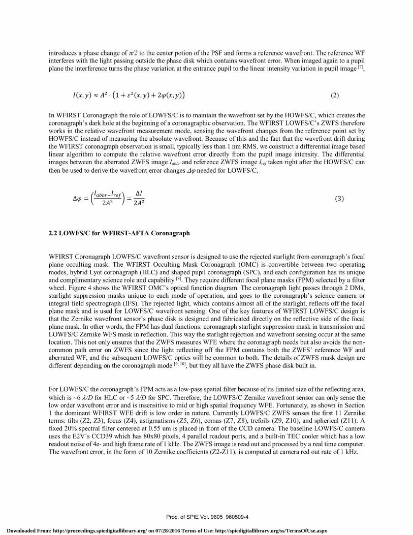
introduces a phase change of /2 to the center potion of the PSF and forms a reference wavefront. The reference WF interferes with the light passing outside the phase disk which contains wavefront error. When imaged again to a pupil plane the interference turns the phase variation at the entrance pupil to the linear intensity variation in pupil image [7],
( , ) ≈ ⋅ 1 + ( , ) + 2 ( , ) (2)
In WFIRST Coronagraph the role of LOWFS/C is to maintain the wavefront set by the HOWFS/C, which creates the coronagraph’s dark hole at the beginning of a coronagraphic observation. The WFIRST LOWFS/C’s ZWFS therefore works in the relative wavefront measurement mode, sensing the wavefront changes from the reference point set by HOWFS/C instead of measuring the absolute wavefront. Because of this and the fact that the wavefront drift during the WFIRST coronagraph observation is small, typically less than 1 nm RMS, we construct a differential image based linear algorithm to compute the relative wavefront error directly from the pupil image intensity. The differential images between the aberrated ZWFS image Iabbr and reference ZWFS image Iref taken right after the HOWFS/C can then be used to derive the wavefront error changes needed for LOWFS/C,
∆ = 2 = ∆2 (3)
2.2 LOWFS/C for WFIRST-AFTA Coronagraph
WFIRST Coronagraph LOWFS/C wavefront sensor is designed to use the rejected starlight from coronagraph’s focal plane occulting mask. The WFIRST Occulting Mask Coronagraph (OMC) is convertible between two operating modes, hybrid Lyot coronagraph (HLC) and shaped pupil coronagraph (SPC), and each configuration has its unique and complimentary science role and capability [8]. They require different focal plane masks (FPM) selected by a filter wheel. Figure 4 shows the WFIRST OMC’s optical function diagram. The coronagraph light passes through 2 DMs, starlight suppression masks unique to each mode of operation, and goes to the coronagraph’s science camera or integral field spectrograph (IFS). The rejected light, which contains almost all of the starlight, reflects off the focal plane mask and is used for LOWFS/C wavefront sensing. One of the key features of WFIRST LOWFS/C design is that the Zernike wavefront sensor’s phase disk is designed and fabricated directly on the reflective side of the focal plane mask. In other words, the FPM has dual functions: coronagraph starlight suppression mask in transmission and LOWFS/C Zernike WFS mask in reflection. This way the starlight rejection and wavefront sensing occur at the same location. This not only ensures that the ZWFS measures WFE where the coronagraph needs but also avoids the non-common path error on ZWFS since the light reflecting off the FPM contains both the ZWFS’ reference WF and aberrated WF, and the subsequent LOWFS/C optics will be common to both. The details of ZWFS mask design are different depending on the coronagraph mode [9, 10], but they all have the ZWFS phase disk built in.
For LOWFS/C the coronagraph’s FPM acts as a low-pass spatial filter because of its limited size of the reflecting area, which is ~6 /D for HLC or ~5 /D for SPC. Therefore, the LOWFS/C Zernike wavefront sensor can only sense the low order wavefront error and is insensitive to mid or high spatial frequency WFE. Fortunately, as shown in Section 1 the dominant WFIRST WFE drift is low order in nature. Currently LOWFS/C ZWFS senses the first 11 Zernike terms: tilts (Z2, Z3), focus (Z4), astigmatisms (Z5, Z6), comas (Z7, Z8), trefoils (Z9, Z10), and spherical (Z11). A fixed 20% spectral filter centered at 0.55 um is placed in front of the CCD camera. The baseline LOWFS/C camera uses the E2V’s CCD39 which has 80x80 pixels, 4 parallel readout ports, and a built-in TEC cooler which has a low readout noise of 4e- and high frame rate of 1 kHz. The ZWFS image is read out and processed by a real time computer. The wavefront error, in the form of 10 Zernike coefficients (Z2-Z11), is computed at camera red out rate of 1 kHz.
Proc. of SPIE Vol. 9605 960509-4
Downloaded From: http://proceedings.spiedigitallibrary.org/ on 07/28/2016 Terms of Use: http://spiedigitallibrary.org/ss/TermsOfUse.aspx

FromTelescope
Pupil Focal plane Lyot Field stop Filtermask mask + mask mask wheel
i ZWFS
FSM
FM1DM1
-
I
AO` 01:1R3 i R3
OAP1 i OAP2
t-
'kJ
o
HOWFS/C Ì r-
HLC
SPC
FocusingOptics
R1OAP2
N NIE
J
DM2 R2OAP1
-o.
R2OAP2
N_EN
FS FS PBSOAP1 OAP2
Coronagraph BenchIBM J
Fig. 4 Functional illustration of WFIRST Coronagraph instrument (CGI) bench. Starlight from the telescope and relay optics enters CGI bench at left through the fast steering mirror (FSM). Two deformable mirrors (DM1 and DM2) correct the wavefront phase and amplitude for high contrast imaging. Relay optics are off-axis parabolas (OAP). The WFIRST CGI can operate in either HLC or SPC mode with Hybrid Lyot Coronagraph masks (top row) and Shaped Pupil Coronagraph masks (bottom row) being able to be switched in via filter wheels at pupil or image planes, indicated with dot-dashed lines in the figure. A selectable mirror sends coronagraph light to either the imaging camera (FPA) behind a polarizing beam splitter (PBS) or the integral field spectrograph (IFS). The rejected starlight from the focal plane mask, which has the LOWFS/C phase mask built-in, is captured by the LOWFS/C lenses and sent to LOWFS/C camera. The LOWFS/C subsystem, indicated by the thicker lined components and thicker dash lines, controls FSM, Focusing Optics, and DM1 with different updating speeds as labeled in their corresponding signal paths.
The ZWFS sensed WFE is used to control corresponding wavefront correctors by the LOWFS/C, as shown in Fig 4. The sensed tip-tilt (Z2, Z3) is used to drive the Fast Steering Mirror (FSM) control loop with command update rate of 1 kHz to suppress the LoS jitter and drift. Since the thermally induced WFE drift is very slow the sensed low order WFE (Z4 – Z11) can be time-averaged over long period (minutes) to reduce the sensor noise without compromising the control bandwidth. The sensed focus term (Z4) is used to control the coronagraph’s focusing optics which is an actuated fold flat in a focused beam designed as a part of the coronagraph instrument. Focus is one of the dominant mode of WFIRST WFE drifts. Correcting it with a dedicated Focusing Mirror (FM) will reduce the stroke burden on the deformable mirror. The rest of low order wavefront error terms (Z5 – Z11) sensed by ZWFS are sent to DM1, which is conjugated to the system pupil, for the correction.
Besides LoS jitter the telescope vibration from the reaction wheels will also cause the WFE jitter with frequencies and amplitudes depending on the RW wheel speeds. The RW induced WFE jitter are dominated by a few low order modes such as focus, astigmatisms and comas [1]. For the high frequency (> 2 Hz) wavefront jitters the LOWFS/C does not have the bandwidth to suppress them. However, the modeling has shown that the impact of WFIRST WFE jitter on coronagraph contrast and contrast stability is negligible, at about 10-11 to10-10 level. Some of the WFE jitter effect can also be removed during the coronagraph image post-processing. Furthermore from the recorded the ZWFS data we can also evaluate the uncompensated LoS and WFE jitters and use the information for data editing, discarding some science exposures in which the residual jitters are too large.
Proc. of SPIE Vol. 9605 960509-5
Downloaded From: http://proceedings.spiedigitallibrary.org/ on 07/28/2016 Terms of Use: http://spiedigitallibrary.org/ss/TermsOfUse.aspx

PFTP Pupil Phase 0..4'38
r
¿WFSA.aInnSg e:612a 812
D
C
PIxeYptedZWFSflelerenee
,,,,, v ,pexumea nws le e le
R.N.! ZWFS oinerentisi hmor IGelS
d
2.3 Zernike wavefront sensor modeling and performance analysis
To analyze the performance of the Zernike wavefront sensor, a diffraction model has been developed which includes WFIRST-AFTA pupil and total system optical transmission (0.24), HLC and SPC FPMs with the built-in ZWFS phase disk, the initial wavefront from coronagraph’s HOWFS/C, and the ZWFS CCD camera. Example images in Fig 5 show the ZFWS modeling process. For photometry, a GV0 star spectral is used with a 20% ZWFS spectral filter centered at 561 nm for rejected starlight and the star magnitude varies from MV = 0 to MV = 8. The pupil sampling on the ZWFS camera is 16x16 pixels, which has been chosen to optimize the sensor signal-to-noise ratio (SNR) and minimize WFE modes cross-talk. The detector model is based on the E2V CCD39 chip with 4 e- read out noise, 1 e- dark noise at 1 kHz frame rate, and 80% to 87% quantum efficiency (QE) across the spectral band of ZWFS.
Fig. 5 Example images of ZWFS modeling process using the HLC/ZWFS focal plane mask. The images on the left column are the amplitude and phase error at WFIRST-AFTA entrance pupil. Here the phase error is 3 nm (RMS) astigmatism (Z5). The images in middle column are, from top to bottom, the high resolution ZWFS reference (no phase error) image, the aberrated image corresponding to 3 nm of Z5, and the differential image between the aberrated and reference image. The images on the right are, from top to bottom, the corresponding pixelated (16x16 pixels) reference, aberrated, and differential images. The differential images resemble the phase error input and the pixelated differential image (lower right) is the signal for ZWFS sensing.
Using the ZWFS model we have studied the performance of ZWFS against various parameters such as the star magnitude, detector noise, sensor spectral bandwidth, ZWFS phase disk diameter and depth. One of the important ZWFS performance metrics is the ZWFS’s noise equivalent sensing error. It measures how the sensor performs when the photon and detector noise are present. Figure 6 shows the noise equivalent LoS angle and noise equivalent sensing error for three ZWFS configurations. From the plots we can see that the ZWFS noise equivalent sensing error is dominated by the photon noise with sensing errors and star magnitudes following the simple power law. Only for fainter stars of MV > 7, the noise curves begin to deviate from this power law, indicating that the detector noise becomes more significant. It is important to emphasize that these noise curve are evaluated at camera readout rate of 1 kHz, i.e. at exposure of 1 msec. For slowly drifting low order WFE the sensor can gain much performance through image averaging over longer period of time which is equivalent to increasing the stellar brightness. For example, if we average camera images for 1 minute, the equivalent exposure time increases by a factor of 60,000, then the equivalent stellar magnitude gain is MV ≈ -12. The 4 nm sensing error from an MV = 5 star for HLC ZWFS will be
Proc. of SPIE Vol. 9605 960509-6
Downloaded From: http://proceedings.spiedigitallibrary.org/ on 07/28/2016 Terms of Use: http://spiedigitallibrary.org/ss/TermsOfUse.aspx

10'0 1 2 3 4 5 6 7 8 9
Star Magnitude (Mv)
LOSCommand
Off-loadto ACS
ACS RWASpeed
Cfb(s) FSMT -r
(honed-r +RLS--------r- 1
1
t
d = dtona! + dóroadóand
ncamera
Sensor(1000 Hz)
2
10'
Noise Equivalent WFE Sensing Error (nm)
t Simple Phase Disk FPM-t- HLC FPM + DMsi - SPC Bowtie FPM
10'
1020 1 2 3 4 5 6 7 8 9
Star Magnitude (Mv)
>o-2
reduced to 16 pm. More details on the ZWFS modeling and analysis results can be found in the companion paper in this conference [11].
Fig. 6 ZWFS noise performance for a simple Zernike phase disk, HLC, and SPC configurations with the ZWFS camera running at 1 kHz frame rate. The plot on the left is the noise equivalent angle (on-sky) and plot on the right is that of noise equivalent low order wavefront sensing error. PSF differences caused by either diffraction (for the case of SPC) or wavefront (for the case of HLC) increases the ZWFS sensing error compared with an ideal PSF on ZWFS with a simple phase disk.
2.4 Line of sight control loop design and performance analysis
A high level schematic overview of the LoS control loop is shown in Fig 7. There are two control branches. A feedback path is used for compensation of the slow ACS drift. The controller in this branch is designed to reject high frequency sensor noise. A second path is targeted to feed the high frequency tonal information directly forward to the FSM. A couple different possible means of achieving this. Figure 7 shows one possible method using recursive least squares fitting of the tones using RWA wheel speed information [13].
Fig. 7 High level depiction of a proposed jitter compensation loop using a Fast Steering Mirror (FSM). The feedback path is marked by solid lines and the feedforward path is marked by dash lines. The RLS block is the recursive least squares fitting to the high frequency disturbance tones. Disturbances include broadband ACS drift (dbroadband), RWA induced tonal jitter (dtonal), and electronic line noise (dline).
The line-of-sight control uses the Fast Steering Mirror (FSM) with three PZT actuators, which is inherited from the SIM project [12]. The FSM PZT actuators have strain gauge sensors that are used to close a local loop around the PZT
Proc. of SPIE Vol. 9605 960509-7
Downloaded From: http://proceedings.spiedigitallibrary.org/ on 07/28/2016 Terms of Use: http://spiedigitallibrary.org/ss/TermsOfUse.aspx

101
FSM LoS Jitter Correction: Y-axis
E
101co
1:K
10-205 10 15 20 25 30 35 40
Wheel Speed (rev/sec)45
Mv =8Mv =7Mv =6Mv =3Mv = 0No Correction
50 55
displacements. This loop linearizes the hysteresis of the PZTs, cancels drift due to creep, and achieves a bandwidth of 150 Hz.
Figure 8 and Table 1 summarize the modeled FSM loop performance against the WFIRST reaction wheel induced jitter shown in Fig 1. In this model we used the ZWFS sensor noise model for HLC configuration shown in Fig. 6, as well as the measured FSM driver noise. Table 1 shows the fraction of time over which the residual jitter meets three coronagraph performance evaluation criteria, assuming that the wheel speed is uniformly distributed from 10 to 40 rev/sec. More details on LOWFS/C FSM line-of-sight control can be found in the companion paper in this conference [13].
Fig. 8 WFIRST jitter input and the residual LoS jitter with the LOWFS/C FSM loop plotted against the RW wheel speed. The plot shows the Y axis LoS jitter. Lines of different colors represent the residual jitter of different stellar magnitudes, which affect the ZWFS sensor noise.
Table 1. Percentage of time the residual jitters meet the three coronagraph performance evaluation criteria.
Star magnitude (MV) / Jitter (milliarcsec)
X jitter residual over 10 - 40 rev/sec Y jitter residual over 10 - 40 rev/sec≤ 0.4 ≤ 0.8 ≤ 1.6 ≤ 0.4 ≤ 0.8 ≤ 1.6
0 95% 98% 100% 97% 100% 100%3 95% 98% 100% 97% 100% 100%6 83% 98% 100% 93% 100% 100%7 83% 98% 100% 91% 99% 100%8 59% 97% 100% 52% 99% 100%
2.5 Low order WFE control with the deformable mirror
The WFIRST LOWFS/C uses the coronagraph’s DM1 to correct sensed low order wavefront drift Z5 to Z11. The deformable mirror actuator height versus control voltage curve of each actuator is nonlinear and these curves are slightly different for each actuator. Each DM actuator’s gain will be calibrated around its bias voltage, but some calibration error is inevitable. We carried out an investigation to determine how tight the requirements on DM actuator
Proc. of SPIE Vol. 9605 960509-8
Downloaded From: http://proceedings.spiedigitallibrary.org/ on 07/28/2016 Terms of Use: http://spiedigitallibrary.org/ss/TermsOfUse.aspx

WV
300
200
100
-100
-200
-300
(150
100
50
-50
-100
-150
150
100
50
0
-50
-100
-150
gain knowledge have to be in order to use the DM for correcting low order WFE terms above focus without unacceptably degrading the coronagraph contrast. To understand the impact of such actuator gain-errors on the LOWFS/C, we introduced two types of actuator gain-error factors: the static gain-error factors of and time-varying or dynamic gain-error factors of , that is,
= 1+ 1+ (4)
where is the desired LOWFS/C DM commands for the current iteration DM control (denoted by subscript i) and is the actual DM poke the actuator realized, which includes the DM actuator gain error factors.
Fig. 9 Example of DM actuator height map with and without the DM gain calibration error. In this example the DM is trying to compensate the WFE error from the WFIRST-AFTA telescope drift, which is the OPD map on the left. The sign of OPD is flipped in this plot for easy comparison with the DM height maps. On the DM actuator height maps (middle and right plots) each pixel represents the height of an actuator in the 48x48 actuator DM. The DM actuator height map in the middle is from DM control without DM gain calibration error while the actuator height map on the right is from the DM with actuator gain calibration error of = 20% and = 10%.
Figure 9 illustrates the effect of the DM gain calibration error. It shows that the DM gain calibration error will cause post LOWFS/C correction residual WFE to fall into mid to high spatial frequency because the DM actuator gain calibration error is, in general, random among the actuators. The LOWFS/C sensor, however, will not able to sense these mid to high spatial frequency DM residual error due to its limitation in spatial resolution. Therefore using a deformable mirror to correct the low order WFE commanded by the LOWFS/C may adversely affect the coronagraph’s performance because these mid to high spatial frequency WFE will cause extra speckles in the coronagraph dark field and degrade the coronagraph contrast.
We use the LOWFS/C model to simulate the LOWFS/C closed loop sensing and control using DM1 for the thermally induced WFIRST WF drift shown in Fig. 2. Figure 10 plots the RMS contrast difference with different DM actuator gain errors when the DM is used to correct the same thermal drift shown in Fig 2. In this simulation the LOWFS/C sensing error is v small, by using an MV=5 star and integration time of 1000 sec, so we can compare only the DM gain error effect. From Fig. 10 we can see that for a typical WFIRST WFE drift if we wish to maintain the contrast stability to ~10-10 level we need to calibrate the DM actuator gain to better than 10% ( = 0.1). Furthermore because in our model we have defined the DM gain error as the proportional terms to the DM stroke (Eq. 4), if the WFE drift is larger the DM calibration requirement will be even tighter. Otherwise we would have to rely on the “data editing” to discard the coronagraph science data when the WFE drift is too large. More details on LOWFS/C DM gain error analysis can be found in the companion paper in this conference [14].
Proc. of SPIE Vol. 9605 960509-9
Downloaded From: http://proceedings.spiedigitallibrary.org/ on 07/28/2016 Terms of Use: http://spiedigitallibrary.org/ss/TermsOfUse.aspx

DM Actuator Gain Error on Coronagraph Contrast
o
4 5 6 7 8
Angular Distance (VD)9 10
Fig. 10. RMS contrast averaged across the WFIRST-AFTA observation time span. Each differential contrast map is equal to a contrast map at a time-step minus the nominal. The individual RMS change computed over azimuth was obtained first, then averaged over all of the time steps. Finally it is plotted versus field radius. The curves represents different DM actuator statics gain errors, from ideal (S = 0%) to S = 20% while the dynamic gain errors is set to be ½ of the static gain errors.
3 LOWFS/C TESTBED DESIGN AND PRELIMINARY LOWFS/C IN-AIR
CALIBRATION AND TEST
To demonstrate and evaluate the performance of LOWFS/C with HLC and SPC coronagraph modes under the representative WFIRST-AFTA environment we have designed an Optical Telescope Assembly (OTA) Simulator to inject the expected WFIRST wavefront drift and LoS jitter into the OMC coronagraph testbed. The OTA Simulator acts as the coronagraph testbed star source, providing point source light with adjustable brightness and spectral bandwidth. It also creates the pupil shape that mimics the obscured 2.4 meter WFIRST-AFTA telescope. Before the OTA Simulator is delivered to the OMC coronagraph testbed it will be first tested on the LOWFS/C testbed. Besides OTA Simulator sub-bench the LOWFS/C testbed consists of the Zernike wavefront sensor (ZWFS) with a commercial CCD camera running at 780 Hz frame rate, the Fast Steering Mirror (FSM) for LoS jitter correction, and the focusing mirror (FM). Figure 11 and its caption describe the optical layout and functions of the OTA Simulator and LOWFS/C testbed.
The OTA Simulator relies on the precision linear movement of the powered optics (telescope, SM, OAP2) to generate small (sub-nm) low order wavefront error. Pure low order aberration modes such as focus, coma, astigmatism, and spherical can be generated by properly moving the powered optical mirrors. To accurately move the powered optics we use PZT actuators with strain gauges which can provide microns of motion with sub nm precision and linearity better than 0.2%.
Proc. of SPIE Vol. 9605 960509-10
Downloaded From: http://proceedings.spiedigitallibrary.org/ on 07/28/2016 Terms of Use: http://spiedigitallibrary.org/ss/TermsOfUse.aspx

LOWFS OAP
Occulter &ZWFS Mask
OAP2
PinholeS
PM
AFTA Pupil Mask
OAP1
litter Mirr ava
OAP3 Fold Mirr
Coronagraph
FSM
(pupil)
Focusing Mirr
(pupil)
CCD
s
/
t-}
.FE ofZ2=a1000.Onm
J,
30D
<0J
50J
600í
.
1500
1003
0
-500
-1500
100 200 300 400 500 600RMS=1030.6nm, P-V=3910.Onm
Mean Zemike WFE1000
600
Ê5 600
á 400$
200
Ñ0
x19W
.
.. . .
2001 2 3 4 5 6 7 8 9 10 11
Zemike Term
700
200
300
400
600
AW FE of Z4 ..20.0 nm
100 200 300 400 500 600RMS=15.9nm, P-V=135.2nm
Mean Zemike WFE
5
U
1 2 3 4 5 6 7 8 9 10 11
Zemike Term
15
f0
50E
rti 0
AWFEofZ5=14.0nm
lox
200 4" No390
500 ,-
600 .111100 200 300 400 500 600
RMS=16.5nm, P.V=199.4nm
Mean Zemike WFE
1 2 3 4 5 6 7 8 9 10 11
Zemike Temi
AWFEofZ7=+50.0nm
200
1
300
40D
500
600
` ,41.661.1.190...
100
p
0
40
-100
100 200 300 400 500 600RMS=49.9nm, PN=271.1nm
Mean Zemike WFE60
50.
Ê.qp
3p.U1+ p.
7r N 10
o
.x.r
.r:lpl .
. . . .
f10
1 2 3 4 5 6 7 8 9 10 11
Zemike Term
Fig. 11 The OTA Simulator and the LOWFS/C testbed. The plot on the left is the optical layout and picture on the right is the testbed after integration, oriented the same way as the optical layout on the left. The OTA Simulator uses a fiber illuminated pinhole as the star. The light from the pinhole is collimated by a miniature telescope with the scaled down WFIRST-AFTA telescope primary mirror (PM) and secondary mirror (SM). A pupil mask behind the secondary mirror support creates the WFIRST-AFTA pupil shape which has the SM obscuration and the shadows of the SM supporting struts. This pupil is then relayed by a pair of OAPs (OAP 1 and 2) to the Jitter Mirror (JM) which is a small flat mirror on a PZT tilt stage with strain gauges. It is used to inject the high frequency LoS jitter into the system. After the JM another pair of OAPs (OAP 3 and 4) create a collimated beam and form another pupil just outside the OTA Simulator sub-bench for interface with the testbed interface optics, which, on the LOWFS/C testbed, is the FSM. In OTA Simulator the miniature AFTA telescope, SM, and OAP2 are all actuated in 6 degrees of freedoms by PZT actuators to create the needed low order WFE modes that simulate the WFIRST-AFTA WFE drift. The LOWFS/C testbed starts with the FSM. The following LOWFS OAP focuses beam on the ZWFS mask. The beam is folded by a flat mirror on a linear stage acting as the focus correcting mirror. The ZWFS light reflects from a focal plane mask and is collected and collimated by Lens 1 and re-imaged to LOWFS/C CCD camera by Lens 2 & 3. They form a pupil image of 16x16 pixels on the LOWFS/C CCD camera.
Fig. 12. Zygo interferometer measurement of the OTA Simulator generated pure aberration modes. The plots show the example aberration modes (from left to right) of tilt (Z2), focus (Z4), astigmatism (Z5), and coma (Z7) created by OTA Simulator. On top of each panel is the OPD difference between the nominal and the commanded OTA Simulator measured by the Zygo. The commanded pure mode RMS aberration is listed on top of each panel and the decomposed Zernike components RMS values are shown in the bar chart below with the RMS value of the corresponding mode labeled. Besides the mode meant to be created the bar charts also show the presence of small amount of other modes, likely from the air turbulence or testbed drift. The relative strength of these “undesired” modes becomes negligible for the strong pure modes, such as tilt and coma.
Proc. of SPIE Vol. 9605 960509-11
Downloaded From: http://proceedings.spiedigitallibrary.org/ on 07/28/2016 Terms of Use: http://spiedigitallibrary.org/ss/TermsOfUse.aspx

FSM Calibration: Ch2 = + / -50mV
X-Tilt (Z2)
Y-Tilt (Z3)
5 10 15 20
Time (sec)
25 30
After the LOWFS/C testbed integration and alignment the OTA Simulator has been calibrated using a Zygo interferometer. First, the influence function of each PZT was measured with the Zygo. They were compared with the OTA Simulator FEM modeled influence functions. The measured and modeled data have shown a very good match within the fluctuations from the lab seeing. The influence functions of all the PZTs are then used to create a control matrix which enables us to command the PZTs of OTA Simulator to create a “pure” WFE aberration mode, such as focus, astigmatism and coma. To overcome the air turbulence we use the full stroke of PZTs for some weak modes, such as astigmatism. Figure 12 shows the Zygo measurement of these pure aberration modes created by OTA Simulator. The Zygo measurements show an excellent agreement between the commanded mode and measured mode. During our vacuum test we will use these calibration to create small sub nm WFE to simulate WFIRST WFE drift.
As a part of LOWFS/C testbed hardware and software functional test a preliminary in-air FSM closed loop test has been conducted. In the test the ZWFS uses a Hybrid Lyot Coronagraph focal plane mask which has the Zernike WFS phase disk built in. During this in-air test, the OTA Simulator’s Jitter Mirror was not activated so all of the LoS disturbance comes from the air turbulence in the lab. The turbulence is random in nature and does not follow a tonal model like the reaction wheels. Therefore, this test aimed for a low bandwidth feedback suppression of the slower components of the atmospheric turbulence. Feedforward control was not included in this test. Figure 13 shows the example of the FSM to ZWFS calibration. We used the square wave chopping signal to overcome the random tilt from the air turbulence. The ZWFS measurement matches expected WF tilt from the Zygo calibrated FSM. Figures 14 shows the LoS control loop performance. The bandwidth of the controller can be seen to be around 6 Hz. This is sufficient demonstration for the compensation of the slow telescope ACS pointing errors that are 2 Hz and below. High frequency disturbances are not intended to be suppressed in this particular experiment.
Fig 13. FSM to ZWFS calibration. During the test for this plot one of the FSM actuator (Ch 2) is driven with square wave of ±50mV with period of 2 sec while ZWFS signals were recorded at 780 Hz. Ch2 is one the three FSM actuators and its movement causes chopping responding ZWFS signals in both Z2 (X-tilt) and Z3 (Y-tilt) channels although Z2 is much stronger due to the Ch2 orientation relative to the ZWFS camera. The plot also shows that on top of FSM induced chopping signals the air turbulence also cause the tilt variations. The ZWFS measurement matches expected WF tilt from the Zygo calibrated FSM.
Currently we have finished LOWFS/C in-air I&T and calibration. The testbed has recently been installed into a small vacuum chamber. The LOWFS/C vacuum test will follow. During the vacuum test we will test the ZWFS sensor sensitivity floor, linearity, and noise performance. We will also test the LoS control by introducing the WFIRST-AFTA like jitter using the jitter mirror.
Proc. of SPIE Vol. 9605 960509-12
Downloaded From: http://proceedings.spiedigitallibrary.org/ on 07/28/2016 Terms of Use: http://spiedigitallibrary.org/ss/TermsOfUse.aspx

10
10
10°
100(r)0w 10>LL
F 10
104
10510' 10° 101
Frequency (Hz)
PSD of Tilt: Open and Closed Loops
- - -- Open - XOpen -Y
- Closed - X- Closed - Y
10
40
30
20
10
0
1
-20
300
AFTA LOWFS /C FSM Loop
Open Loop Closed oop
20 40 60 80
Time (sec)
X-Tilt (Z2)Y-Tilt (Z3)
100 120
Fig 14. In-air test of the FSM low bandwidth feedback loop for drift compensation. In this test the disturbance source was primarily due to air turbulence. Plot on the left is time series of the ZWFS measured tilts before and after closing the loop at about 60 seconds. Plot on the right is the PSD of the same data.
4 CONCLUSION
WFIRST Coronagraph requires a low order wavefront sensing and control subsystem to maintain the coronagraph’s contrast stability. WFIRST Coronagraph LOWFS/C uses the Zernike phase contrast wavefront sensor, which is combined with the coronagraph’s focal plane mask, to sense the low order wavefront drift and line-of-sight jitter from the rejected starlight. Working in the differential image mode the ZWFS can provide the sensitivity needed to sense and correct the expected WFIRST LoS jitter and wavefront drift. Simulations of LOWFS/C closed loop jitter suppression and low order WFE correction have been done for the realistic disturbances generated by the current observatory models and on-orbit operating scenarios. The fidelity of these observatory models will increase over time, but the initial results are promising. A LOWFS/C testbed including the OTA Simulator has been built to simulate WFIRST-AFTA telescope LoS jitter and wavefront drift and to perform stand-alone testing of the LOWFS/C subsystem before integrating it with the coronagraph testbed. Early lab results using an HLC focal plane mask have shown that the ZWFS sensor is capable of detecting sub milliarcsecond tilt, as needed for WFIRST coronagraph to meet its science requirements. A preliminary closed-loop pointing stabilization test using FSM has successfully demonstrated the feedback control functionality of the testbed. WFIRST Coronagraph LOWFS/C performance in vacuum will be tested and characterized over the summer of 2015.
ACKNOWLEDGMENTS
The work published in this paper is supported by NASAs WFIRST mission study office. The authors also are grateful for the contributions of many scientists and engineers in WFIRST team. The research was carried out at the Jet Propulsion Laboratory, California Institute of Technology, under a contract with the National Aeronautics and Space Administration.
Proc. of SPIE Vol. 9605 960509-13
Downloaded From: http://proceedings.spiedigitallibrary.org/ on 07/28/2016 Terms of Use: http://spiedigitallibrary.org/ss/TermsOfUse.aspx

REFERENCES
[1] “WFIRST cycle 5 closeout jitter," Internal communication (2015). [2] J. Krist, B. Nemati, H. Zhou, E. Sidick, “An overview of WFIRST/AFTA coronagraph optical modeling”, Proc.
SPIE 9605, pp. 9605-4, (2015). [3] J. Krist, B. Nemati, B. Mennesson, “Numerical modelling of the proposed WFIRST-AFTA coronagraphs and their
predicted performances”, submitted to JATIS, (2015). [4] A. Give’on, B. Kern, S. Shaklan, D. Moody, L. Pueyo, “Broadband wavefront correction algorithm for high-
contrast imaging system,” Proc. SPIE, 6691, 66910A (2007). [5] K. Zernike, MNRAS, 94, 377 (1934) [6] J. K. Wallace, S. Rao, R. M. Jensen-Clem, G. Serabyn, “Phase-Shifting Zernike Interferometer Wavefront Sensor”,
Proc. SPIE 8126, 81260F-1 (2011) [7] F. Shi, K. Balasubramanian, R. Hein, R. Lam, D. Moore, J. Moore, K. Patterson, I. Poberezhskiy, J. Shields, E.
Sidick, H. Tang, T. Truong, J. K. Wallace, X. Wang, D. Wilson, “Low Order Wavefront Sensing and Control for WFIRST-AFTA Coronagraph”, submitted to JATIS, (2015).
[8] R. Demers, F. G. Dekens, R. J. Calvet, Z. Chang, R. T. Effinger, E. M. Ek, L. Jones, A. Loc, B. Nemati, C. Noecker, T. Neville, H. Pham, H. Tang, J. Villalvazo, “Requirements and design reference mission for the WFIRST-AFTA coronagraph instrument”, Proc. SPIE 9605, pp. 9605-1 (2015).
[9] K. Balasubramanian, V. White, K. Yee, P. Echternach, R. Muller, M. Dickie, E. Cady, D. Ryan, I. Poberezhskiy, H. Zhao, B. Kern, J. Krist, B. Nemati, K. Patterson, A.J. Riggs, N. Zimmerman, and N. J. Kasdin, “WFIRST-AFTA coronagraph shaped pupil masks: Design, Fabrication and Characterization”, submitted to JATIS, (2015).
[10] J. Trauger, B. Gordon, J. Krist, D. Moody, “Hybrid Lyot Coronagraph for WFIRST-AFTA: coronagraph design and performance metrics”, submitted to JATIS, (2015).
[11] X. Wang, J. K. Wallace, F. Shi, “Zernike wavefront sensor (ZWFS) modeling development for low order wavefront sensing (LOWFS) on wide-field IR space telescope (WFIRST) / astrophysics focused telescope assets (AFTA)”, Proc. SPIE 9605, pp. 9605-79, (2015).
[12] A. Toorian, R. Smythe, M. Morles, J. Carson, J. Moore, “Flight qualification and performance testing of SIM precision optical mechanisms”, Proc. SPIE 7734 (2010).
[13] K. Patterson, J. Shields, X. Wang, H. Tang, A. Azizi, P. Brugarolas, M. Mandic, and F. Shi, “Control Design for Momentum-Compensated Fast Steering Mirror for the WFIRST-AFTA Coronagraph Instrument”, Proc. SPIE 9605, pp. 9605-83, (2015).
[14] Erkin Sidick, and F. Shi, "Effect of DM actuator gain errors on the WFIRST/AFTA coronagraph contrast performance", Proc. SPIE 9605, pp. 9505-5, (2015).
Proc. of SPIE Vol. 9605 960509-14
Downloaded From: http://proceedings.spiedigitallibrary.org/ on 07/28/2016 Terms of Use: http://spiedigitallibrary.org/ss/TermsOfUse.aspx