low-power embedded device used in healthcare systems
TRANSCRIPT

BULETINUL INSTITUTULUI POLITEHNIC DIN IAŞI Publicat de
Universitatea Tehnică „Gheorghe Asachi” din Iaşi Tomul LV (LIX), Fasc. 1, 2009
SecŃia AUTOMATICĂ şi CALCULATOARE
LOW-POWER EMBEDDED DEVICE USED IN HEALTHCARE SYSTEMS
BY
NICOLAE ALEXANDRU BOTEZATU and ANDREI STAN
Abstract. The need for chronic and geriatric care at home, due to a great number request of patients who do not wish to stay in clinics, has increased the demand of homecare monitoring wearable mobile devices. Low power consumption is essential in the continuous process of monitoring vital signs and can be achieved combining very high storage capacity, wireless communication, and ultra-low power circuits together with firmware management of power consumption. This approach allows the patient to move unconstraint around an area. The design of a ultra low power wireless monitoring system based on low power circuits, flash memory storage and 2.4 GHz communications is presented in this paper.
Key words: healthcare, low-power, patient monitoring, telemedicine, wireless.
2000 Mathematics Subject Classification: 92C50, 68M12, 94C99.
1. Introduction
Phenomena of ageing population observed in most developed countries
and prevalence of chronic diseases have increased the need for chronic and
geriatric care at home [1]. The task of patient monitoring may be achieved by
telemedicine (enabling medical information-exchange as the support to distant-
decision-making) and telemonitoring (enabling simultaneous distant-monitoring
of a patient and his vital functions) both having many advantages over
traditional practice. Doctors can receive information that has a longer time span
than a patient’s normal stay in a hospital and this information has great long-
term effects on home health care, including reduced expenses for healthcare.
Despite the increased interest in this area, a significant gap remains
between existing sensor network designs and the requirements of medical
monitoring. Most telemonitoring networks are intended for deployments of
38 Nicolae Alexandru Botezatu and Andrei Stan
stationary devices that transmit acquired data at low data rates and rather high
power consumption. By outfitting patients with wireless, wearable vital sign
devices, collecting detailed real-time data on physiological status can be greatly
simplified [2]. But, the most important effect is the widely social integration of
peoples with disabilities or health problems that need discreet and permanent
monitoring [3].
2. System Design
2.1. Overview
This paper proposes the development of a low power wireless system, to suite the needs of geriatric health centers and retirement homes, for real time or off-line monitoring of their patients health status.
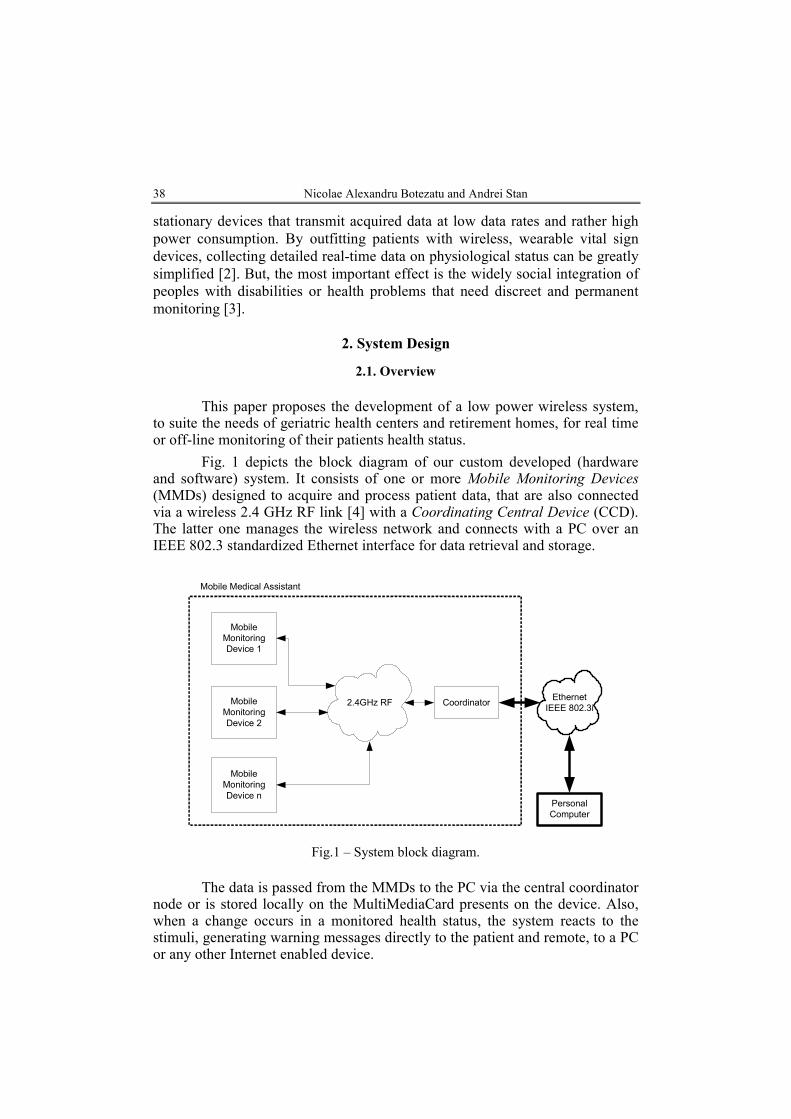
Fig. 1 depicts the block diagram of our custom developed (hardware and software) system. It consists of one or more Mobile Monitoring Devices (MMDs) designed to acquire and process patient data, that are also connected via a wireless 2.4 GHz RF link [4] with a Coordinating Central Device (CCD). The latter one manages the wireless network and connects with a PC over an IEEE 802.3 standardized Ethernet interface for data retrieval and storage.
Mobile
Monitoring
Device 1
Mobile
Monitoring
Device 2
Mobile
Monitoring
Device n
2.4GHz RF CoordinatorEthernet
IEEE 802.3i
Personal
Computer
Mobile Medical Assistant
Fig.1 – System block diagram.
The data is passed from the MMDs to the PC via the central coordinator node or is stored locally on the MultiMediaCard presents on the device. Also, when a change occurs in a monitored health status, the system reacts to the stimuli, generating warning messages directly to the patient and remote, to a PC or any other Internet enabled device.

Bul. Inst. Polit. Iaşi, t. LV (LIX), f. 1, 2009 39
Every battery powered mobile monitoring device can attend only one patient at a time, for monitoring, processing and storage of the following physiological parameters: EKG, heart rate, blood oxygen saturation, body temperature and galvanic skin response. The monitoring device also analyzes the patient’s movement in order to detect any abnormal patterns: muscular spasms, patient falling or paralysis (Fig. 2).
EKG
SaO2 and
Heart Rate
Galvanic Skin
Response
(GSR)
2.4GHz RF
RF
Communication
Interface (xBee
Transceiver)
Mobile Monitoring Device
Body
Temperature
Acute
Movement
Detection (ex.
Seizure)
Real Time
Clock (RTC)
MMC Data
Storage
Fig.2 – Mobile Monitoring Device block diagram.
All the parameters can be acquired independently, by this the power
consumption footprint being adapted uniquely to the patient. The radio link is based on an IEEE 802.15.4 standard compliant module with low-power capabilities. Also, an on-board RTC keeps the time reference for the processed and stored data.
2.2. System Acquisition Blocks
2.2.1. Pulsoximeter. In the nineteenth century it was discovered that the
colored substance in blood, hemoglobin, which is a protein bounded to the red blood cells, was also its carrier of oxygen. Also it was noticed that the absorption of visible light by a hemoglobin solution varied with oxygenation.

40 Nicolae Alexandru Botezatu and Andrei Stan
This happens because the two common forms of the molecule, oxidized hemoglobin (HbO2) and reduced hemoglobin (Hb), have different optical spectrum in the wavelength range of 500 – 1000 nm (Fig. 3 a) [4].
Fig. 3 – Absorption spectra of Hb and HbO2 (a); Transmission of light trough a finger with the attenuation caused by:
A – arterial blood, V – venous blood, T – tissues (b).
There are many times when it would be useful to be able to monitor the
blood oxygen level as a drop can induce a severe medical condition called hypoxia (death of body cells in the absence of oxygen). Considering this need, in the late 1930’s was designed the first pulse oximeter. Pulse oximetry is a non-invasive and continuous method of determining the amount of HbO2 and Hb in a persons blood supply. This is accomplished by implementing the Beer-Lambert Law, which in this case relates the concentration of oxygen in the blood to the amount of light absorbed when transmitted trough a body part. The absorption of the light transmitted trough the medium can be calculated with Eq. (1):
(1) AINOUT eII −⋅= ,
where: IOUT is the intensity of light transmitted trough the medium, IIN − the intensity of light going into the medium, A − the absorption factor. This method assumes that the attenuation of light by a body segment can be split into three independent components: arterial blood, venous blood and tissues (Fig. 3 b). If we assume that the increase in attenuation of light is caused only by the inflow of arterial blood into the body part, the oxygen saturation of the arterial blood can be calculated by subtracting the DC component of the attenuation from the total attenuation, leaving only the cardiac-synchronous pulsatile component for the dual wavelength determination of the oxygen saturation. Pulseoximeters make use of red (wavelength 660 nm) and infra red (wavelength 940 nm) light to determine the percentage of oxygenated hemoglobin present in the blood. These two wavelengths are chosen because at 660 nm deoxygenated hemoglobin has a higher absorption, whereas at 940 nm,

Bul. Inst. Polit. Iaşi, t. LV (LIX), f. 1, 2009 41
oxygenated hemoglobin has a higher absorption. Once the absorption levels are detected, it is possible to determine the ratio of the absorption between the deoxygenated and oxygenated hemoglobin at the different wavelengths [5]. The block diagram of the solution implemented is presented in Fig. 4.
Transimpedance
Amplifier
LED light output
level control
Red LED
IR LED
PIN Diode
Finger sensor clip
LED ON/OFF
control
PIN Diode
connector
Amplifier
stage
ADCMUX
LED
selection
DAC0
LED light output
level adjust
DC component
tracking (IIR filter)
DAC1
FIR LP filter
(30Hz cutoff freq)
Zero crossing
detection
Heart Rate
Calculation
SaO2 Calculation
OA1
OA2
Fig. 4 – Pulsoximeter block diagram.
The two LEDs are time multiplexed, the PIN Diode being alternately
excited by the two light sources. The current passing trough the diode is fed into a transimpedance amplifier OA1 (current input – voltage output). The signal is then further amplified 30x times, and the DC component of the signal is subtracted using the feedback loop formed by the ADC, the IIR filter and DAC1. The filter extracts the DC component of the signal that is used as an offset input to the operational amplifier OA2; only the difference between the two inputs would be amplified, thus eliminating the DC part. The AC signal is then used to determine the light output level for the two LEDs, as the DC component of the two raw signals must be in the same range (the two signals must be proportional). Furthermore, the digitalized AC signal is filtered to remove the line (50 – 60 Hz) and artificial light (110 – 120 Hz) noise.
The heart rate is determined using a zero crossing algorithm and the oxygen saturation level is calculated as described above based of the Beer-Lambert Law.
2.2.2. Electrocardiograph. An electrocardiogram (EKG) is a graphical representation of the voltage that contracts the myocardium (heart muscle) over a period of time. It gives accurate information of the health status and the performance of the heart.
The cardiac muscle contracts spontaneous and rhythmic under the
42 Nicolae Alexandru Botezatu and Andrei Stan
influence of a network of pacemaker cells, resulting in a polarization and depolarization of the muscle cells. These cycles can be perceived by measuring the potential at the skin surface, because of their electrical nature. This way the heart can be described as a variable voltage source (over time), developing a potential of approximately 1mV between various body points. This can be measured by placing electrode contacts on the body. Nowadays, the standardization of the points where the electrodes are applied, makes possible the comparison of electrocardiograms as taken from person to person and from time to time from the same person.
There are several constraints concerning the acquisition of this physiologic signal: the input of the circuit must be sensitive enough to perceive low amplitude signals (1 mV peak to peak); the input impedance must be in the range of mega ohms; also the leakage current on the inputs must be less than 1µA. The common mode rejection ratio (CMRR) must be high and the input stage must have a linear response in the range of 0.05 – 150 MHz. Because we are focusing on a portable device, thus being battery powered, this stage must have a single supply requirement [6].
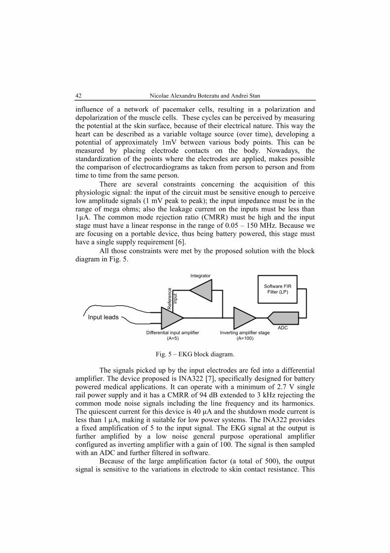
All those constraints were met by the proposed solution with the block diagram in Fig. 5.
Differential input amplifier
(A=5)
Inverting amplifier stage
(A=100)
Integrator
Reference
input
ADC
Input leads
Software FIR
Filter (LP)
Fig. 5 – EKG block diagram.
The signals picked up by the input electrodes are fed into a differential
amplifier. The device proposed is INA322 [7], specifically designed for battery powered medical applications. It can operate with a minimum of 2.7 V single rail power supply and it has a CMRR of 94 dB extended to 3 kHz rejecting the common mode noise signals including the line frequency and its harmonics. The quiescent current for this device is 40 µA and the shutdown mode current is less than 1 µA, making it suitable for low power systems. The INA322 provides a fixed amplification of 5 to the input signal. The EKG signal at the output is further amplified by a low noise general purpose operational amplifier configured as inverting amplifier with a gain of 100. The signal is then sampled with an ADC and further filtered in software.
Because of the large amplification factor (a total of 500), the output signal is sensitive to the variations in electrode to skin contact resistance. This

Bul. Inst. Polit. Iaşi, t. LV (LIX), f. 1, 2009 43
results in a variation of the DC content of the amplified differential signal and manifests as a drift in the baseline of the EKG. The phenomenon is also called baseline wandering. This problem is managed by using an analog integrator schematic designed with a general purpose operational amplifier. The DC content of the 5x amplified EKG signal is integrated and fed back into the reference input of the input differential amplifier. This feedback allows the INA322 to maintain a constant DC level at the output, regardless of the changes in skin contact resistance.
2.2.3. Thermometer. The human body has a constant internal temperature of 36.8 degrees Celsius, generated by metabolic processes which produce approximately 1 Watt per body kilogram during rest state. The heat produced in the deep structures of the body is transmitted to its surface trough blood flow and direct conduction. Abnormalities in a person’s temperature are most likely to be symptoms for circulatory or infectious pathology and that is why over time there have been standardized different body sites for temperature measurement. We targeted the axillary region for the measurements considering easy access and less stress for the patient. The process was accomplished using the integrated temperature sensor TMP101 [8].
2.2.4. Galvanic skin response. The galvanic skin response (GSR), also known as electro dermal response, measures changes in electrical resistance across two regions of the skin. The feedback from this physiological parameter can be used to diagnose or determine excessive stress levels, dermatological conditions and even may help asset the internal state of a person with autism. The GSR analog stage applies a constant current of 1 milliamp to the skin; the voltage between the electrodes is amplified and sampled by an ADC for further discrete processing (Fig. 6).
AmplifierADC
Constant
Current
Source
Input leads
Software FIR
Filter (LP)
Fig. 6 – Galvanic Skin Response block diagram.
2.2.5. Acute movement detection. The acute movement detection block is used to detect abnormal muscle contractions and dangerous movement events (a patient falling or a patient trying to stand up if his condition prohibits it). The main part is represented by the MMA7260 [9], 3-Axis analog output

44 Nicolae Alexandru Botezatu and Andrei Stan
Accelerometer, which has selectable sensitivity in the range 1.5 g−6 g. The outputs of the accelerometer are filtered using an RC network and fed into an impedance matching circuit before being sampled with the ADC.
3. Implementation
3.1. Firmware
The firmware developed for this system consists of two main sections:
mobile monitoring device firmware and coordinator firmware. Furthermore, the firmware on the MMD is divided in other two parts due to the asymmetric multiprocessor hardware. The idea to include two processing units into the MMD (one master and one slave) is based on the need of processor speed and memory that could not be satisfied by only one 16 bit, low-power, Texas Instruments MSP430 microcontroller [10], [11]. The tasks between the two microcontrollers were divided according to their (software) complexity; the slave processor takes care of the EKG and SaO2 acquisitions and the master processor deals with the rest of the parameters and the communication link.
To maintain a low-power profile for this application, all the integrated circuits used have at least one stand-by mode to preserve energy consumption. Also the code was written to make use of those low-power features of the hardware components.
START (main
code)
System Initialize
Low Power Sleep
Mode
START (Master
link Receive ISR)
Command
Acquire EKG data Acquire SaO2 data
Send data to
master
Set Command
Code
Fig.7 – MMD Slave microcontroller software diagram.

Bul. Inst. Polit. Iaşi, t. LV (LIX), f. 1, 2009 45
In Fig. 7 is shown the workflow for the software on the slave microcontroller of the MMD. After the initialization stage, the microcontroller alternates between a low-power sleep mode and the actual acquisition and processing of the data, alternating between the two parameters according to the commands received from the master. When the master sends a command to start or to stop the acquisition process of one of the parameters, the corresponding hardware blocks are passed from or into stand by mode accordingly.
Acquire
temperature data
START (main
code)
System Initialize
Low Power Sleep
Mode
Command
Read EKG dataAcquire
accelerometer dataRead SaO2 data Acquire GSR data
Data outputGet time refferenceSend data via RF
link
Save data on MMC
START (RF link
Receive ISR)
Set Command
Code
Fig.8 – MMD Master microcontroller software diagram.
The software of the master microcontroller on the MMD (Fig. 8) has the same basic structure as the software on the slave one; the difference is that it also manages three data links: the one with the slave counterpart, the RF data link and the MMC interface. Also, the data acquisition parts are less resources consuming due to smaller processing needs. To reduce the system overhead during intense data transmission periods, one of the criteria in choosing the microcontrollers was the presence of a DMA module with at least 3 channels. Because of this, the overall working frequency of the system was reduced, resulting in less power consumption.

46 Nicolae Alexandru Botezatu and Andrei Stan
START (Ethernet
link Receive ISR)
Message type
START (main
code)
System Initialize
Low Power Sleep
Mode
START (RF link
Receive ISR)
Message type
Active PC link
Send init data
request to PC
Send data to PC
Message type
Send default init
data to MMD
Init Data
YES
Send init data to
MMDExecute command
Misc
NO
Init
Fig. 9 – Coordinator’s microcontroller software diagram.
The coordinator module has the following four roles: management of
the RF network, execution of commands received from a PC, initializations of new MMDs, bridging function between the MMDs and a PC for data transfer. This module reacts when a new MMD has entered the system and needs initialization parameters, sending a request to the connected PC via the Ethernet link. It also reacts to commands received via Ethernet and that must be executed locally or sent to one or more MMDs (Fig. 9).
3.2. Low-Power Considerations
3.2.1. Hardware. All components used for this system are ultra-low
power components, such as: MSP430 microcontroller (only 400 uA active current), MMA7260 (100 uA active current) and RF modem (47 mA transmit current, 500 uA idle current).
All these devices features ultra-low power modes of operation and all these modes of power-saving are controlled in firmware.
3.2.2. Firmware. The developed firmware consists of several tasks and
each of them manages a particular resource. The communication between tasks is implemented with semaphores and waiting queues allowing a high level of parallelism between processes. Each process may be individually enabled or disabled. This feature is very important in increasing the flexibility of the application: if real time monitoring is desired, then MMC Process may be disabled and RF link Process is enabled, if only long term monitoring is desired than the MMC Process is enabled and RF link Process may be disabled. This has a positive impact on power consumption because only the resources that are needed are enabled for use.
Encryption of personal data is provided. Some files that store personal

Bul. Inst. Polit. Iaşi, t. LV (LIX), f. 1, 2009 47
data related to the patient are encrypted and can be accessed only using the proper decryption algorithm. Only a part of the files are encrypted because there must be kept a balance between power consumption and computing power requirements. For space saving, a light compression algorithm may be activated as an extra feature of the device. The activation of this feature has a negative impact on the overall power consumption.
The communication process implements an application layer protocol for data exchange between the device and other wireless enabled devices. The communication requirements must be limited to a minimum rate in order to save power. The RF module is powered on when a message has to be sent. The message transmission rate is kept low by using internal buffering and burst communication. The RF module can be also waked up by an incoming message that may embed commands to the device.
3.2.3. Power analysis. In order to determine the low-power profile of the system, test were ran while monitoring the power consumption. Different acquisition patterns were used, as well as alternation between data storage and wireless data communication. The power supply module of the mobile device used for the test was made of a 2000 mAh rechargeable battery and a step-up DC-DC converter MAX1724 [12].
In Fig. 10 there are two graphs that show the current drawn from the battery over 250 milliseconds when the pulsoximetry and temperature acquisition modules are turned on. Also, in one case the data is saved locally and in the other case the data is transmitted over the RF link.
Fig.10 – Power trend for two acquisition scenarios.

48 Nicolae Alexandru Botezatu and Andrei Stan
The graphs show four acquisition and process cycles for the physiological parameters alternating with low-power sleep modes; after that, to the right of the graphs, the power trend of the saving or transmitting process of the data is visible.
The results of the developed test are in Table 1. All the tests were conducted with a fully charged battery, and were stopped when at least one of the data acquired and processed was considered unreliable. The number of monitored parameters influences the power consumption and battery life although in all the cases the differences between the test results and the analytical results were under 15%.
Table 1
Test and Analytic Results of the for Power Analysis
Estimate medium power consumption
mA
Estimate battery life
h
Achieved medium power consumption
mA
Achieved battery life
h Monitored parameters
Via RF
On MMC
Via RF
On MMC
Via RF
On MMC
Via RF
On MMC
SaO2 and
Temperature 11.2 16.6 178 120 11.7 16 174 124
Galvanic Skin
Response
4.3 6.3 465 317 4,9 7 416 290
All Parameters
16.7 19.5 120 102 16.7 19.4 122 103
4. Conclusions
The work of this paper focuses on design and implementation of an ultra low power wearable device able to acquire patient vital parameters, causing minimal discomfort and allowing high mobility. The proposed system could be used as a warning system for monitoring during normal activity or physical exercises.
Test results showed that so far we achieved a satisfactory power footprint, the system being able to sustain its functionality for at least 103 h on a 2000 mAh battery. By having the ability to start and stop the monitoring process of the parameters individually, the system can extend its functionality to as long as 400 h. The accuracy of the acquired physiological parameters was also tested, the medium error achieved by the system being 16.45% , with respect to commercial patient monitors, taking into account that the MMDs were not calibrated.
In conclusion, this paper presents some challenges of hardware and software design for medical wearable device based on low-power medical

Bul. Inst. Polit. Iaşi, t. LV (LIX), f. 1, 2009 49
sensors and microcontroller with a recent tremendous impact in many medical applications.
Received: December 10, 2008 “Gheorghe Asachi” Technical University of Iaşi, Department of Computer Science e-mails: [email protected] [email protected]
R E F E R E N C E S
1. **
* Population Ageing. United Nations Population Division Department of Economic and Social Affairs, http://www.un.org/esa/population/publications/ aging99/ a99pwld.htm.
2. Hung K., Wearable Medical Devices for Tele-Home Healthcare. Proceedings of the 26th Annual International Conference of the IEEE EMBS, USA, September 1-5, 2004.
3. **
* Report on the World Social Situation 2007. United Nations Department of Economic and Social Affairs, http://www.un.org/esa/socdev/rwss/docs/ rwss07_fullreport.pdf.
4. **
* xBee/xBee Pro Product Manual. DigiStream, 2006.
5. Bachiochi J., Light-to-Frequency Conversion. Pulse and Oxygen Content. Circuit Cellar, 174, January 2005.
6. Chan V., Underwood S., A Single-Chip Pulsoximeter Design Using the MSP430. Texas Instruments Application Note, 2005.
7. Raju M., Heart-rate and EKG Monitor Using the MSP 430FG439. Texas Instruments Application Note, 2007.
8. **
* INA322 Datasheet. Texas Instruments, 2006.
9. **
* TMP101 Datasheet. Texas Instruments, 2002.
10. **
* MMA7620Q Datasheet. Freescale Semiconductor, 2008.
11. **
* MSP430x2xx Family User’s Guide. Texas Instruments, 2007.
12. **
* MSP430x4xx Family User’s Guide. Texas Instruments, 2007.
13. **
* MAX1724 Datasheet. Maxim Semiconductor, 2001.
DISPOZITIV MEDICAL CU CONSUM REDUS PENTRU MONITORIZAREA PACIENłILOR
(Rezumat)
Nevoia pentru îngrijirea afecŃiunilor cronice şi geriatrice la domiciliu, datorată
numărului mare de pacienŃi care refuză internarea în clinici specializate, a mărit cererea de dispozitive mobile de monitorizare. Consumul redus de curent este esenŃial în procesul de monitorizare continuă a semnalelor vitale, putând fi realizat prin combinarea unei capacitaŃi mari de stocare a datelor, comunicaŃii fără fir şi circuite cu

50 Nicolae Alexandru Botezatu and Andrei Stan
consum redus împreună cu management-ul software a puterii consumate. Această abordare le permite pacienŃilor să se deplaseze necondiŃionat într-un perimetru, aceştia nefiind incomodaŃi de prezenŃa dispozitivului datorită dimensiunii şi greutăŃii sale reduse.
Această lucrare prezintă o soluŃie posibilă pentru proiectarea unui sistem de monitorizare cu consum redus, care permite stocarea datelor pe memorii SecureDigital şi monitorizarea lor prin intermediul comunicaŃiilor radio în banda de 2,4 GHz. Parametrii fiziologici monitorizaŃi sunt frecvenŃa cardiacă, gradul de oxigenare a sângelui, temperatura corporală şi rezistenŃa galvanică a pielii. De asemenea, sistemul conŃine un electrocardiograf cu un canal şi un bloc de detecŃie pentru mişcări anormale (căzături, crize de epilepsie etc.).
Rezultatele obŃinute în urma testării dispozitivului propus, din punct de vedere al consumului, au fost satisfăcătoare, acesta având o autonomie de până la 400 ore.