low power fm antenna systems.pdf
TRANSCRIPT

Low Power
FM Antenna Systems

6340 Sky Creek Dr, Sacramento, CA 95828 | T: 916.383.1177 | F: 916.383.1182 JAMPRO.com
JAMPRO Yagi 3 Element Antenna Hot‐Dip Galvanized Steel Directional Radiation Pattern Suitable for Medium and High Power FM Stacked Array
J3YF
J3YF 3 ELEMENT FM YAGI ANTENNA
ELECTRICAL FEATURES
Band: 87.5 – 108 MHz
Bandwidth: FM Band
Average Gain: 4.5 dBd (6.65 dBi)
VSWR: < 1.3:1
Polarization: Vertical (Horizontal upon Request)
Max Power: 5000 W (Single Carrier)
Connector: 7/8” EIA
Dimensions: 54”x68”x3”/133x173x8 cm
Net weight: 26.5 lbs/12 kg
MECHANICAL FEATURES
Materials: Body and Bracket hot dip galvanized steel, Stainless steel
hardware, Teflon isolators, silicone O‐Rings
Mounting:
The antenna is supplied with pipe mounting for both horizontal and ver‐
tical polarization.
Standard option for pole
Ø 3.5” to 4.5” / 90 to 114mm
Also available on request option for pole
Ø 2.36” to 2.99” / 60 to 76mm
Mounting Brackets: Included
Distance Between Antennas: 2.5m ‐ 3m / 8.25 ft ‐ 9.84 ft
These directional antennas can be used in vertical or horizontal polari‐
zation to set up systems having directional , semi‐directional and Omni
directional diagrams.
All specifications subject to change without notice

ANTENNA SPECIFICATIONS J3YF-2 ANTENNA TYPE: J3YF-2 ANTENNA DESCRIPTION: JAMPRO 3 FM Yagi antenna system Includes: J3YF FM Yagi antenna, 2 each Power splitter, 2-way Feed cables, 2 each Standard mounting brackets ELECTRICAL SPECIFICATIONS Est. power gain: 6.98 dBd Array Configuration: 2 Levels Electrical beam tilt: -0° Null fill: 0% Antenna VSWR: ≤ 1.3:1 Max. Input Power Rating: 5 kW Antenna input impedance: 50 ohm
Antenna input connector size: 7/8” EIA
NOTE: THESE SPECIFICATIONS ARE PREDICTIONS BASED ON AVAILABLE DATA. THE
ACTUAL PERFORMANCE MAY DIFFER FROM THESE DUE TO THE ELECTRICAL, MECHANICAL AND MEASURED LIMITATIONS AT YOUR FREQUENCIES.

6340 Sky Creek Dr, Sacramento, CA 95828 | T: 916.383.1177 | F: 916.383.1182 www.JAMPRO.com
VERTICAL DIPOLE FM BROADCAST ANTENNA The JAMPRO JBVP is a vertically polarized broad band side mount FM antenna consisting of a Balun fed vertical dipole, power divider and heliax coaxial feed lines. The JBVP vertical dipole antenna is constructed of stainless steel and brass inner conductor. All associated brackets and hardware are made of hot dipped, galvanized steel for many years of dependable service.
JBVP
Vertical or elliptical polarization
VSWR: 1.25:1 over 6 MHz
Excellent diplexing capabilities
Medium power handling
Beam tilt and null fill available
Custom directional patterns available
Reduced element spacing for minimizing RF levels
The JAMPRO vertically polarized FM array is completely assembled full size and factory tuned on an electrically similar tower structure to insure proper impedance match and low VSWR. The antenna features symmetrical band bass and is ideal for HD Radio ™ and analog broadcasting.

6340 Sky Creek Dr, Sacramento, CA 95828 | T: 916.383.1177 | F: 916.383.1182 www.JAMPRO.com
NOTES: 1. All inputs EIA flange, female.
2. Feed points: ~5 ft. below center (mid-aperture).
3. Power derating occurs above 2,000 ft. elevation.
4. Power and dB gains are typical for horizontal and vertical components.
5. Custom mounting brackets available.
6. Free space azimuth circularity is +/- 2dB.
7. Polarization is vertical.
8. Power gain is based on half wave dipole in free space.
9. Optional fine matcher available. Contact factory for details.
OPTIONS: Options available include FCC Directionalization, Pattern Measurement Service, beam tilt, null fill, and special mounting brackets.
Since many factors contribute to a station's compliance with the FCC exposure guidelines for radio frequency radiation, JAMPRO ANTENNAS, INC. cannot accept any responsibility in this matter. The station must examine and determine its status based on each individual situation. For reduced low angle radiation near the tower, a low RFR model of this antenna is available. Contact the factory for pricing data and further details.
*All specifications subject to change without notice.
# Bays Power Gain Gain (dB) Power kW
1 0.92 -0.37 2.5 2 1.9 2.8 5 3 3 4.77 7.5 4 4.2 6.23 10 5 5.3 7.24 12.5 6 6.6 8.19 15 8 8.4 9.25 17.5
10 10.6 10.3 20 12 13.2 11.2 20 16 17.6 12.45 20
JBVP

FM ANTENNA SPECIFICATIONS JBVP-1 ANTENNA DESCRIPTION: Vertically Polarized Broadband FM Sidemount Antenna MODEL: JBVP-1 ELECTRICAL SPECIFICATIONS Power gain: .9x / -4.5 dBd Array Configuration: 1 Bay Electrical beam tilt: 0° Null fill: 0% Antenna VSWR: 1.25:1 over 6 MHz Power Rating: 2.5 kW Antenna input impedance: 50 ohm Antenna input connector size, EIA: 1-5/8” EIA NOTE: THESE SPECIFICATIONS ARE PREDICTIONS BASED ON AVAILABLE DATA. THE
ACTUAL PERFORMANCE MAY DIFFER FROM THESE DUE TO THE ELECTRICAL, MECHANICAL AND MEASURED LIMITATIONS AT YOUR FREQUENCIES.
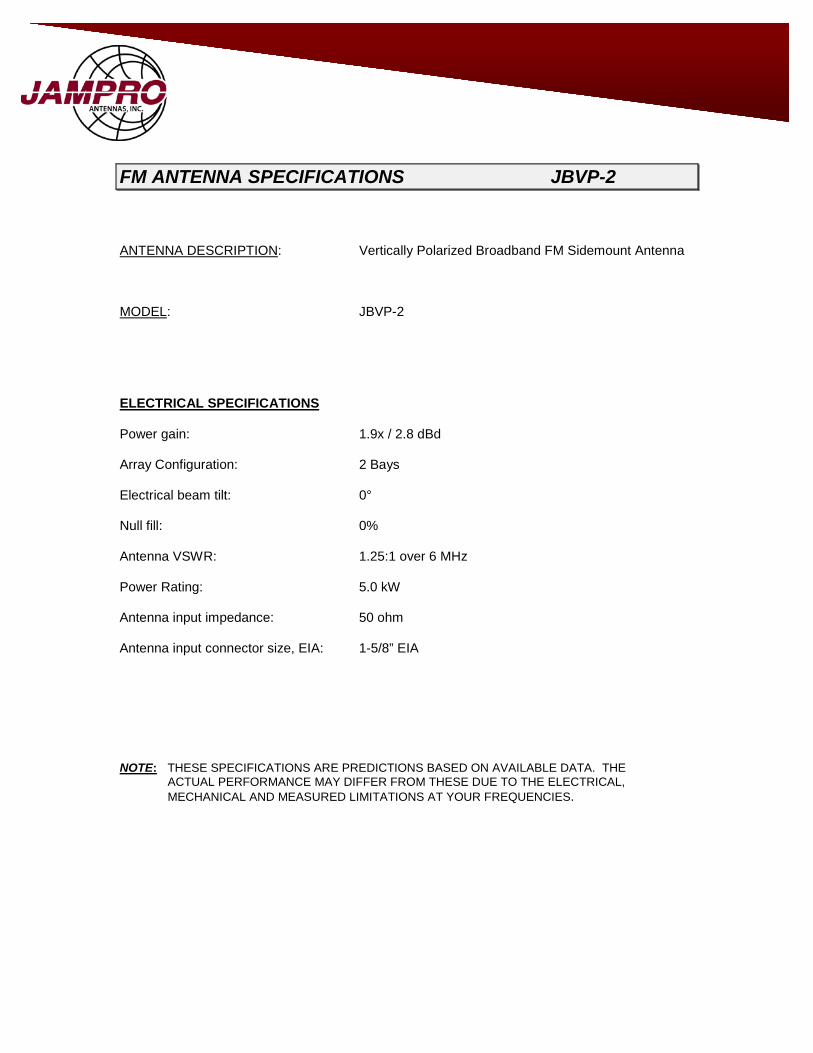
FM ANTENNA SPECIFICATIONS JBVP-2 ANTENNA DESCRIPTION: Vertically Polarized Broadband FM Sidemount Antenna MODEL: JBVP-2 ELECTRICAL SPECIFICATIONS Power gain: 1.9x / 2.8 dBd Array Configuration: 2 Bays Electrical beam tilt: 0° Null fill: 0% Antenna VSWR: 1.25:1 over 6 MHz Power Rating: 5.0 kW Antenna input impedance: 50 ohm Antenna input connector size, EIA: 1-5/8” EIA NOTE: THESE SPECIFICATIONS ARE PREDICTIONS BASED ON AVAILABLE DATA. THE
ACTUAL PERFORMANCE MAY DIFFER FROM THESE DUE TO THE ELECTRICAL, MECHANICAL AND MEASURED LIMITATIONS AT YOUR FREQUENCIES.

THE JAMPRO LOW POWER FM BROADCAST ANTENNA
The JAMPRO JLPC antenna is the low power version of the popular PENETRATOR antenna, which has become an industry standard for quality and performance. Each bay consists of a PENETRATOR style radiating element with a rigid shunt feed line supported by a galvanized steel mounting bracket; standard round leg mounting brackets for a uniform face tower are included with each antenna. Silver plated inner conductor connectors are used throughout for maximum contact life and minimum power loss. Outstanding Performance for HD Radio, Stereo and SCA Operation. Excellent VSWR and Bandwidth 1.10:1 +/- 150 KHz typical
JLPC
Reduced RF Arrays
Pattern Measurement Study
Custom Mounting Brackets Available
Electrical Beam Tilt
Null Fill
Rugged Mechanical Construction
Mounting True Circular Polarization
Range 88-108 MHz
DC Grounded at Each Bay for Lighting Protection
Marine Brass & Copper for Longevity
6340 Sky Creek Dr, Sacramento, CA 95828 | T: 916.383.1177 | F: 916.383.1182 JAMPRO.com

Notes:
1. Weights and wind loads contact factory.
2. Wind loads based on 50/33 PSF (98 MHz, midband)
3. Feed points, when end fed is 3 ft below bottom bay; when center fed is 9’. 6” below center
4. All inputs are EIA flange, female
5. Power derating occurs above 2,000 feet elevation. Con-tact factory for details
6. Power and Db gains are typical for horizontal and vertical components
7. Special mounting brackets are available
8. Other combinations of EIA inputs and power ratings available
9. Free space azimuth circularity is ± 2.0 dB
10. Polarization is right hand, clockwise circular
11. Power gain is based on half wave dipole in free space
6340 Sky Creek Dr, Sacramento, CA 95828 | T: 916.383.1177 | F: 916.383.1182 JAMPRO.com
Since many factors contribute to a station's compliance with the FCC exposure guidelines for radio frequency radiation, JAMPRO ANTENNAS, INC. cannot accept any responsibility in this matter. The station must examine and determine its status based on each individual situation. For reduced low angle radia-tion near the tower, a low RFR model of this antenna is available. Contact the factory for pricing data and further details.
*All specifications are subject to change without notice.
JLPC
# Bays Power Gain dB Gain FS @ 1 Mi. Safe Input Power kW
Weight (lbs)
Wind load (lbs)
1 0.46 -3.37 93.2 1
2 1.00 0.00 136.7 2
3 1.50 1.76 168.4 3
4 2.10 3.22 199.2 4
5 2.70 4.31 225.2 4
6 3.20 5.05 246.0 4
8 4.30 6.34 285.2 4
10 5.50 7.40 322.4 4
12 6.60 8.20 353.2 4
Contact Factory

FM ANTENNA SPECIFICATIONS JLPC-1
ANTENNA DESCRIPTION: Circularly Polarized Low Power FM Sidemount Antenna *Factory Tuned MODEL NUMBER: JLPC-1
ELECTRICAL SPECIFICATIONS Est. power gain: .46x / -3.37 dBd Array Configuration: 1 Bay Electrical beam tilt: 0° Null fill: 0% Antenna VSWR: 1.1:1 +/- 150 kHz. Max Input power: 1 kW Antenna input impedance: 50 ohm Antenna input connector size, EIA: 7/8” female NOTE: THESE SPECIFICATIONS ARE PREDICTIONS BASED ON AVAILABLE DATA. THE
ACTUAL PERFORMANCE MAY DIFFER FROM THESE DUE TO THE ELECTRICAL,
MECHANICAL AND MEASURED LIMITATIONS AT YOUR FREQUENCIES.

FM ANTENNA SPECIFICATIONS JLPC-2
ANTENNA DESCRIPTION: Circularly Polarized Low Power FM Sidemount Antenna *Factory Tuned MODEL NUMBER: JLPC-2
ELECTRICAL SPECIFICATIONS Est. power gain: 1.0x / 0.0 dBd Array Configuration: 2 Bays Electrical beam tilt: 0° Null fill: 0% Antenna VSWR: 1.1:1 +/- 150 kHz. Max Input power: 2 kW Antenna input impedance: 50 ohm Antenna input connector size, EIA: 7/8” female NOTE: THESE SPECIFICATIONS ARE PREDICTIONS BASED ON AVAILABLE DATA. THE
ACTUAL PERFORMANCE MAY DIFFER FROM THESE DUE TO THE ELECTRICAL,
MECHANICAL AND MEASURED LIMITATIONS AT YOUR FREQUENCIES.

6340 Sky Creek Dr, Sacramento, CA 95828 | T: 916.383.1177 | F: 916.383.1182 JAMPRO.com
LOW POWER PENETRATOR
The JAMPRO JLLP antenna has been designed to meet the needs of low power and educational stations that require ex-cellent performance on a low budget. This antenna uses the same basic design as the JAMPRO PENETRATOR series of side-mount antennas, which set the industry standard for FM antennas. By using an external and non-pressurized feed system, manufacturing costs are kept to a minimum. Each bay is fed with flexible cable. Configurations with two or more bays are fed through a power divider and cable system that has a 7/8" EIA flange input (female). The antenna ele-ments are constructed of high strength marine brass.
Power rating 4kW maximum
Outstanding VSWR without field tuning
Available for 88-108 MHz
Electrical deicers available
VSWR 1.1:1 +/- 150 kHz
JLLP
TYPICAL SPECIFICATIONS
# of Bays Power Gain Gain (dB) Input Power Net Weight
(lbs.) Windload
(lbs)
1 0.475 -3.23 1 kW 14 36
2 0.955 -0.2 2 kW 34 82
3 1.5 1.76 3 kW 50 114
4 2.05 3.12 4 kW 64 146
*Values provided average/RMS gains; All other stated gains are Peak gains. Gains do not include losses for feed system beam tit or null fill.
Non-ionizing Radiation
Since many factors contribute to a station’s compliance with the FCC exposure guidelines for radio frequency radiation, JAMPRO ANTENNAS,
INC. cannot accept any responsibility in this matter. The station must examine and determine its status based on each individual situation.
*All specifications are subject to change without notice.

FM ANTENNA SPECIFICATIONS JLLP-1
ANTENNA DESCRIPTION: Circularly Polarized Low Power FM Sidemount Antenna *Factory Tuned MODEL NUMBER: JLLP-1
ELECTRICAL SPECIFICATIONS Est. power gain: 0.475x / -3.23 dBd Array Configuration: 1 Bay Electrical beam tilt: 0° Null fill: 0% Antenna VSWR: 1.1:1 ± 150 kHz Max Input power: 1 kW Antenna input impedance: 50 ohm DC Ground Standard Antenna input connector size, EIA: Type "N" Connector
NOTE: THESE SPECIFICATIONS ARE PREDICTIONS BASED ON AVAILABLE DATA. THE ACTUAL PERFORMANCE MAY DIFFER FROM THESE DUE TO THE ELECTRICAL,
MECHANICAL AND MEASURED LIMITATIONS AT YOUR FREQUENCIES.

FM ANTENNA SPECIFICATIONS JLLP-2
ANTENNA DESCRIPTION: Circularly Polarized Low Power FM Sidemount Antenna *Factory Tuned MODEL NUMBER: JLLP-2
ELECTRICAL SPECIFICATIONS Est. power gain: 0.955x / -0.20 dBd Array Configuration: 2 Bays Electrical beam tilt: 0° Null fill: 0% Antenna VSWR: 1.1:1 ± 150 kHz Max Input power: 2 kW Antenna input impedance: 50 ohm DC Ground Standard Antenna input connector size, EIA: 7/8” EIA Female NOTE: THESE SPECIFICATIONS ARE PREDICTIONS BASED ON AVAILABLE DATA. THE
ACTUAL PERFORMANCE MAY DIFFER FROM THESE DUE TO THE ELECTRICAL,
MECHANICAL AND MEASURED LIMITATIONS AT YOUR FREQUENCIES.

JLCP LOW POWER ANTENNA
The JAMPRO JLCP is a low power antenna designed specifically for Omni-Directional low power applications such as LPFM, Trans-lator and Booster stations. The simplicity of the JLCP helix design gives low power stations the flexibility needed to meet their individu-al requirements. It offers Stainless Steel Construction. A stacking harness is included when multiple bay arrays are ordered. The JLCP is field tunable from 88 to 108 MHz. The antenna features: VSWR 1.5:1 or better. Standard 500 watt input rating with 1kW & 2 kW available. Provided for 2” OD pole mount. Optional special brackets available, contact factory.
Stainless steel construction
500 Watts input power option 1 & 2 kW
Circularly polarized
Low maintenance
Easy to install
Field tunable
VSWR: 1.5:1 or better
6340 Sky Creek Dr, Sacramento, CA 95828 | T: 916.383.1177 | F: 916.383.1182 JAMPRO.com
JLCP
# of Bays
Gain (Times)
Gain (dB)
Input Size 500 Watts
Input Size 1000 Watts
Input Size 2000 Watts
Net Weight (lbs.)
Wind load (lbs)
1 0.46 -3.37 Type "N" 7-16 DIN Not Availa-
ble
2 0.955 -0.02 Type "N" 7/8" EIA 7/8" EIA
3 1.5 1.76 Not Available 7/8" EIA 7/8" EIA
4 2.05 3.12 Type "N" 7/8" EIA 7/8" EIA
5 2.55 4.06 Not Available 7/8" EIA 7/8" EIA
6 3.07 4.87 Not Available 7/8" EIA 7/8" EIA
8 4.1 6.12 Not Available 7/8" EIA 7/8" EIA
Contact Factory
*All specifications are subject to change without notice.

FM ANTENNA SPECIFICATIONS JLCP-1
ANTENNA DESCRIPTION: Circularly Polarized Low Power FM Sidemount Antenna *Field Tunable MODEL NUMBER: JLCP-1
ELECTRICAL SPECIFICATIONS Est. power gain: .46x / -3.37 dBd Array Configuration: 1 Bay Electrical beam tilt: 0° Null fill: 0% Antenna VSWR: 1.5:1 ± 150 kHz. Max Input power: 500 Watts Antenna input impedance: 50 ohm
Antenna input connector size, EIA: Type "N" Connector NOTE: THESE SPECIFICATIONS ARE PREDICTIONS BASED ON AVAILABLE DATA. THE
ACTUAL PERFORMANCE MAY DIFFER FROM THESE DUE TO THE ELECTRICAL,
MECHANICAL AND MEASURED LIMITATIONS AT YOUR FREQUENCIES.

FM ANTENNA SPECIFICATIONS JLCP-2
ANTENNA DESCRIPTION: Circularly Polarized Low Power FM Sidemount Antenna *Field Tunable MODEL NUMBER: JLCP-2
ELECTRICAL SPECIFICATIONS Est. power gain: .955x / -0.20 dBd Array Configuration: 2 Bays Electrical beam tilt: 0° Null fill: 0% Antenna VSWR: 1.5:1 +/- 150 kHz. Max Input power: 500 Watts Antenna input impedance: 50 ohm Antenna input connector size, EIA: Type "N" Connector
NOTE: THESE SPECIFICATIONS ARE PREDICTIONS BASED ON AVAILABLE DATA. THE ACTUAL PERFORMANCE MAY DIFFER FROM THESE DUE TO THE ELECTRICAL,
MECHANICAL AND MEASURED LIMITATIONS AT YOUR FREQUENCIES.

Vertically Polarized Booster – Translator or LPFM Antenna
The JAMPRO JLVP is a low power antenna designed specifically for Omni-Directional translator/booster applications. The simplicity of the JLVP design gives low power stations the flexibility needed to meet their individual requirements. A stacking harness may be used to add multiple bays to achieve the required gain. The JLVP is field tunable from 88 to 108 MHz. Higher power ratings are available upon request. The antenna features: VSWR 1.5:1 or better.
JLVP
Stainless Steel Construction
500 Watts Input Power
Option 1 kW
Vertically Polarized
Low Maintenance
Easy to Install
Field Tunable
VSWR <1.5:1
DC Ground at each bay for lightning protection
6340 Sky Creek Dr, Sacramento, CA 95828 | T: 916.383.1177 | F: 916.383.1182 JAMPRO.com
# of BaysGain
(Power)Gain (dB)
Input
Power*
Net
Weight
Wind Load
CaAa Sq “
1 0.955 ‐0.2 500 Watts 11.7 268
2 1.91 2.8 500 Watts 23.4 536
4 4.1 6.12 500 Watts 46.8 1072
6 6.4 8.05 500 WattsContact
Factory
Contact
Factory
All specifications subject to change without notice. *1kW input with 7/8” Input size available-contact factory for pricing

FM ANTENNA SPECIFICATIONS JLVP-1
ANTENNA DESCRIPTION: Vertically Polarized Translator/Booster Antenna ANTENNA MODEL: JLVP-1
ELECTRICAL SPECIFICATIONS Power gain: .955x / -0.2 dBd Array Configuration: 1 Bay Electrical beam tilt: 0° Null fill: 0% Antenna VSWR: 1.5:1 Power Rating: 500 Watts Antenna input impedance: 50 ohm Antenna input connector size: N-type Connector
NOTE: THESE SPECIFICATIONS ARE PREDICTIONS BASED ON AVAILABLE DATA. THE ACTUAL PERFORMANCE MAY DIFFER FROM THESE DUE TO THE ELECTRICAL,
MECHANICAL AND MEASURED LIMITATIONS AT YOUR FREQUENCIES.

FM ANTENNA SPECIFICATIONS JLVP-2
ANTENNA DESCRIPTION: Vertically Polarized Translator/Booster Antenna ANTENNA MODEL: JLVP-2
ELECTRICAL SPECIFICATIONS Power gain: 1.91x / 2.8 dBd Array Configuration: 2 Bays Electrical beam tilt: 0° Null fill: 0% Antenna VSWR: 1.5:1 Power Rating: 500 Watts Antenna input impedance: 50 ohm Antenna input connector size, EIA: N-type Connector
NOTE: THESE SPECIFICATIONS ARE PREDICTIONS BASED ON AVAILABLE DATA. THE ACTUAL PERFORMANCE MAY DIFFER FROM THESE DUE TO THE ELECTRICAL,
MECHANICAL AND MEASURED LIMITATIONS AT YOUR FREQUENCIES.

JCPB FM BROADBAND
BROADCAST ANTENNA
The JAMPRO JCPB side mount antenna is a broadband version of the PENETRATOR antenna, which has become an industry standard for quality and performance. Each bay consists of a PENETRATOR style radiating element supported by a galvanized steel mounting bracket; standard round leg mounting brackets for a uniform face tower are included with each antenna. Silver plated inner conductor connectors are used throughout for maximum contact life and minimum power loss.
JCPB-L
Power rating 500 W
Ideal for broadband & multi frequency applications
Excellent VSWR & bandwidth
Circular polarization
DC ground at each bay & feedpoint radomes available
*Field Tunable
6340 Sky Creek Dr, Sacramento, CA 95828 | T: 916.383.1177 | F: 916.383.1182 JAMPRO.com
Electrical Specifications
Frequency Band II 87.5-108 MHz
Circularity 2.0 dB (Free Space)
Polarization Circular
Impedance 50 ohm
VSWR 1.25:1

NOTES: 1. All inputs EIA flange, female.
2. Power derating occurs above 2,000 ft. elevation.
3. Power and dB gains are typical RMS gains for horizontal and vertical components.
4. Special mounting brackets available.
5. Other combinations of EIA inputs and power rating available.
6. Free space azimuth circularity is 2.0 dB.
7. Polarization is right hand, clockwise, circular.
8. Power gain is based on half wave dipole in free space.
6340 Sky Creek Dr, Sacramento, CA 95828 | T: 916.383.1177 | F: 916.383.1182 JAMPRO.com
Since many factors contribute to a station's compliance with the FCC exposure guidelines for radio frequency radiation (RFR), JAMPRO ANTENNAS, INC. cannot accept any responsibility in this matter. The station must examine and determine its status based on each individual situation. For reduced low angle radiation near the tower, a low RFR model of this antenna is available. Contact the factory for pricing data and further details.
*All specifications subject to change without notice.
# of Bays Power Gain (HPOL) (times) Gain (HPOL) (dB) Power Rating JCPB-L
1 .45 -3.4 500 W
2 .90 -0.4 500 W
3 1.38 1.4 500 W
4 1.95 2.9 500 W
6 3.0 4.8 500 W
8 4.3 6.4 500 W
JCPB-L

JAMPRO.com
FM ANTENNA SPECIFICATIONS JCPB-1L
ANTENNA DESCRIPTION: Circular Polarized Low Power FM Broadband Sidemount Antenna *Field Tunable (factory tuned at an additional cost) MODEL NUMBER: JCPB-1L ELECTRICAL SPECIFICATIONS Est. power gain: 0.45x / -3.4 dBd Array Configuration: 1 Bay Electrical beam tilt: 0° Null fill: 0% Antenna VSWR: 1.25:1 Max input power: 500 W Antenna input impedance: 50 ohm Antenna input connector size: Type “N” NOTE: THESE SPECIFICATIONS ARE PREDICTIONS BASED ON AVAILABLE DATA. THE
ACTUAL PERFORMANCE MAY DIFFER FROM THESE DUE TO THE ELECTRICAL,
MECHANICAL AND MEASURED LIMITATIONS AT YOUR FREQUENCIES.

JAMPRO.com
FM ANTENNA SPECIFICATIONS JCPB-1LR
ANTENNA DESCRIPTION: Circular Polarized Low Power FM Broadband Sidemount Antenna with Feedpoint Radomes *Field Tunable (factory tuned at an additional cost) MODEL NUMBER: JCPB-1LR ELECTRICAL SPECIFICATIONS Est. power gain: 0.45x / -3.4 dBd Array Configuration: 1 Bay Electrical beam tilt: 0° Null fill: 0% Antenna VSWR: 1.25:1 Max input power: 500 W Antenna input impedance: 50 ohm Antenna input connector size: Type “N” NOTE: THESE SPECIFICATIONS ARE PREDICTIONS BASED ON AVAILABLE DATA. THE
ACTUAL PERFORMANCE MAY DIFFER FROM THESE DUE TO THE ELECTRICAL,
MECHANICAL AND MEASURED LIMITATIONS AT YOUR FREQUENCIES.
JAMPRO.com
FM ANTENNA SPECIFICATIONS JCPB-2L
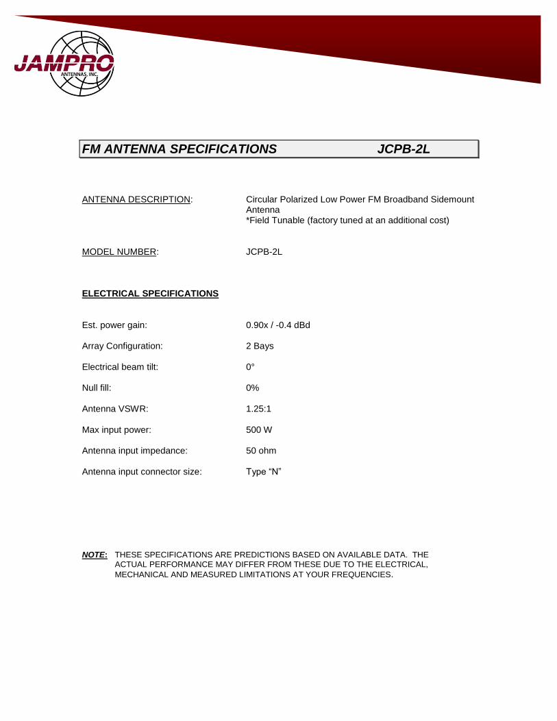
ANTENNA DESCRIPTION: Circular Polarized Low Power FM Broadband Sidemount Antenna *Field Tunable (factory tuned at an additional cost) MODEL NUMBER: JCPB-2L ELECTRICAL SPECIFICATIONS Est. power gain: 0.90x / -0.4 dBd Array Configuration: 2 Bays Electrical beam tilt: 0° Null fill: 0% Antenna VSWR: 1.25:1 Max input power: 500 W Antenna input impedance: 50 ohm Antenna input connector size: Type “N” NOTE: THESE SPECIFICATIONS ARE PREDICTIONS BASED ON AVAILABLE DATA. THE
ACTUAL PERFORMANCE MAY DIFFER FROM THESE DUE TO THE ELECTRICAL,
MECHANICAL AND MEASURED LIMITATIONS AT YOUR FREQUENCIES.
JAMPRO.com
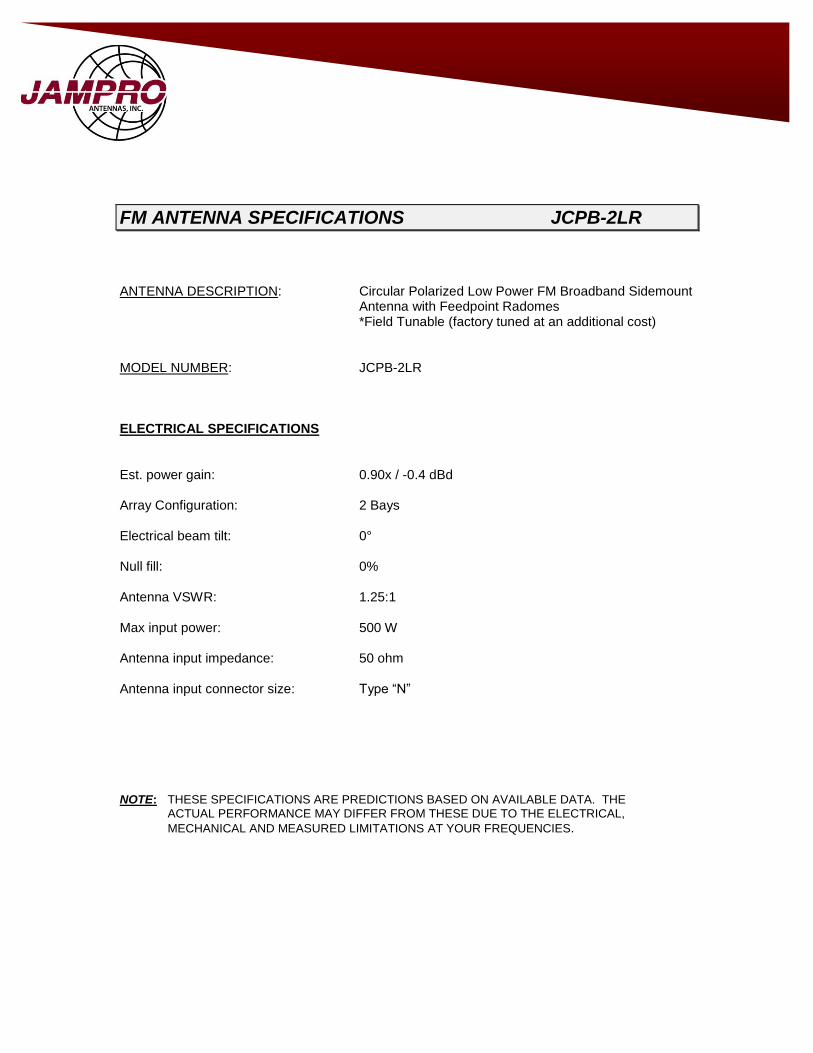
FM ANTENNA SPECIFICATIONS JCPB-2LR
ANTENNA DESCRIPTION: Circular Polarized Low Power FM Broadband Sidemount Antenna with Feedpoint Radomes *Field Tunable (factory tuned at an additional cost) MODEL NUMBER: JCPB-2LR ELECTRICAL SPECIFICATIONS Est. power gain: 0.90x / -0.4 dBd Array Configuration: 2 Bays Electrical beam tilt: 0° Null fill: 0% Antenna VSWR: 1.25:1 Max input power: 500 W Antenna input impedance: 50 ohm Antenna input connector size: Type “N” NOTE: THESE SPECIFICATIONS ARE PREDICTIONS BASED ON AVAILABLE DATA. THE
ACTUAL PERFORMANCE MAY DIFFER FROM THESE DUE TO THE ELECTRICAL,
MECHANICAL AND MEASURED LIMITATIONS AT YOUR FREQUENCIES.

6340 Sky Creek Dr, Sacramento, CA 95828 | T: 916.383.1177 | F: 916.383.1182 www.JAMPRO.com
Band II Folded Dipole Antenna
JFWD
3dB Beamwidth and Gain Table
No of Bays
Gain dBd Beamwidth VRP
Max Power Kg/lbs
1 2.8 73 300W 6/14
2 5.1 29 300W (limited by input power divider)
25/55
4 8.9 13 300W (limited by input power divider)
35/77
6 10.4 8.5 300W (limited by input power divider)
40/89
8 11.7 6.4 300W (limited by input power divider)
55/122
N.B. If higher power ratings are required please contact the factory
Typical Electrical Specifications
Frequency Range 88MHz to 108MHz
Return Loss dB <-14dB
VSWR <1.5:1
HRP Beamwidth 203
Front to back ration 6dB
Polarization Vertical
Connector Type “N”
Mechanical Data
Dipole Ø 15.8mm (5/8”) aluminum with 1.6mm (16swg) wall
Support boom 31.75mm (1 1/4”) square aluminum with 1.6mm
(16swg) wall
Weight 6kg / 14lbs
Weather protection Feed point potted in polyurethane resin

FM ANTENNA SPECIFICATIONS JFWD -1
ANTENNA TYPE: JFWD-1 ANTENNA DESCRIPTION: Band II Folded Dipole Antenna ELECTRICAL SPECIFICATIONS Power gain: 2.8 dBd Array Configuration: 1 Bay Electrical beam tilt: 0° Null fill: 0% Antenna VSWR: <1.5:1 Max Power Rating: 300 watts Antenna input impedance: 50 ohm Antenna input connector size, EIA: Type “N” NOTE: THESE SPECIFICATIONS ARE PREDICTIONS BASED ON AVAILABLE DATA. THE
ACTUAL PERFORMANCE MAY DIFFER FROM THESE DUE TO THE ELECTRICAL,
MECHANICAL AND MEASURED LIMITATIONS AT YOUR FREQUENCIES.

FM ANTENNA SPECIFICATIONS JFWD-2
ANTENNA TYPE: JFWD-2 ANTENNA DESCRIPTION: Band II Folded Dipole Antenna ELECTRICAL SPECIFICATIONS Power gain: 5.1 dBd Array Configuration: 2 Bays Electrical beam tilt: 0° Null fill: 0% Antenna VSWR: <1.5:1 Max Power Rating: 300 watts Antenna input impedance: 50 ohm Antenna input connector size, EIA: Type “N” NOTE: THESE SPECIFICATIONS ARE PREDICTIONS BASED ON AVAILABLE DATA. THE
ACTUAL PERFORMANCE MAY DIFFER FROM THESE DUE TO THE ELECTRICAL,
MECHANICAL AND MEASURED LIMITATIONS AT YOUR FREQUENCIES.
Coaxial Cable
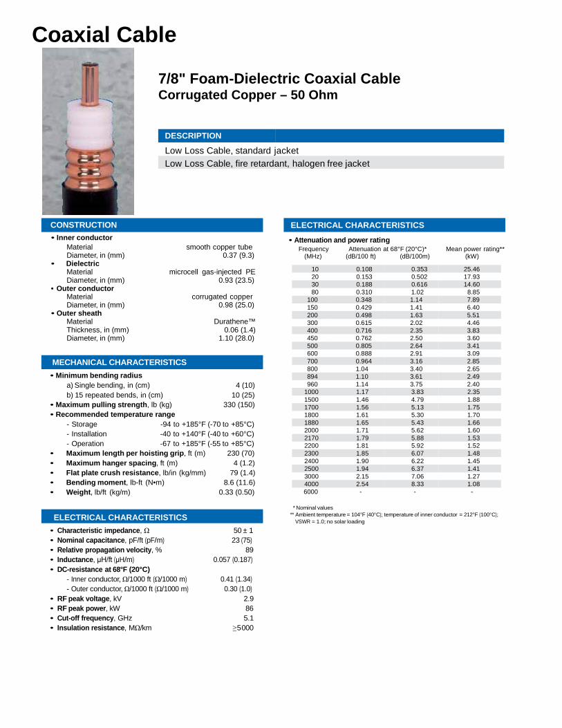
7/8" Foam-Dielectric Coaxial Cable Corrugated Copper – 50 Ohm
DESCRIPTION
Low Loss Cable, standard jacket Low Loss Cable, fire retardant, halogen free jacket
CONSTRUCTION • Inner conductor
Material smooth copper tube Diameter, in (mm) 0.37 (9.3)
• Dielectric Material microcell gas-injected PE Diameter, in (mm) 0.93 (23.5)
• Outer conductor Material corrugated copper Diameter, in (mm) 0.98 (25.0)
• Outer sheath Material Durathene™ Thickness, in (mm) 0.06 (1.4) Diameter, in (mm) 1.10 (28.0)
MECHANICAL CHARACTERISTICS • Minimum bending radius
a) Single bending, in (cm) 4 (10) b) 15 repeated bends, in (cm) 10 (25)
• Maximum pulling strength, lb (kg) 330 (150) • Recommended temperature range
- Storage -94 to +185°F (-70 to +85°C) - Installation -40 to +140°F (-40 to +60°C) - Operation -67 to +185°F (-55 to +85°C)
• Maximum length per hoisting grip, ft (m) 230 (70) • Maximum hanger spacing, ft (m) 4 (1.2) • Flat plate crush resistance, lb/in (kg/mm) 79 (1.4) • Bending moment, lb-ft (N•m) 8.6 (11.6) • Weight, lb/ft (kg/m) 0.33 (0.50)
ELECTRICAL CHARACTERISTICS • Characteristic impedance, Ω 50 ± 1 • Nominal capacitance, pF/ft (pF/m) 23 (75) • Relative propagation velocity, % 89 • Inductance, μH/ft (μH/m) 0.057 (0.187) • DC-resistance at 68°F (20°C)
- Inner conductor, Ω/1000 ft (Ω/1000 m) 0.41 (1.34) - Outer conductor, Ω/1000 ft (Ω/1000 m) 0.30 (1.0)
• RF peak voltage, kV 2.9 • RF peak power, kW 86 • Cut-off frequency, GHz 5.1 • Insulation resistance, MΩ/km ≥ 5000
ELECTRICAL CHARACTERISTICS • Attenuation and power rating
Frequency Attenuation at 68°F (20°C)* Mean power rating** (MHz) (dB/100 ft) (dB/100m) (kW)
10 0.108 0.353 25.46 20 0.153 0.502 17.93 30 0.188 0.616 14.60 80 0.310 1.02 8.85
100 0.348 1.14 7.89 150 0.429 1.41 6.40 200 0.498 1.63 5.51 300 0.615 2.02 4.46 400 0.716 2.35 3.83 450 0.762 2.50 3.60 500 0.805 2.64 3.41 600 0.888 2.91 3.09 700 0.964 3.16 2.85 800 1.04 3.40 2.65 894 1.10 3.61 2.49 960 1.14 3.75 2.40
1000 1.17 3.83 2.35 1500 1.46 4.79 1.88 1700 1.56 5.13 1.75 1800 1.61 5.30 1.70 1880 1.65 5.43 1.66 2000 1.71 5.62 1.60 2170 1.79 5.88 1.53 2200 1.81 5.92 1.52 2300 1.85 6.07 1.48 2400 1.90 6.22 1.45 2500 1.94 6.37 1.41 3000 2.15 7.06 1.27 4000 2.54 8.33 1.08 6000 - - -
* Nominal values
** Ambient temperature = 104°F (40°C); temperature of inner conductor = 212°F (100°C); VSWR = 1.0; no solar loading

Coaxial Cable
7/8" Coaxial Connectors
A-Series DESCRIPTION
N-male, MonoBlock, O-ring N-female, MonoBlock, O-ring 7/16 DIN male, MonoBlock, O-ring 7/16 DIN female, MonoBlock, O-ring
Standard Series DESCRIPTION
N-male, MonoBlock, O-ring N-female, MonoBlock, O-ring 7/16 DIN male, MonoBlock, O-ring 7/16 DIN female, MonoBlock, O-ring
ELECTRICAL • Nominal impedance, Ω 50 • Return loss @ 2.5 GHz, dB -35 • 3rd order intermodulation product, dBc -163 • Temperature range -40°F to +140°F (-40°C to +60°C) • Water immersion testing IP67 & IP68 • Materials
External parts Passivated silver plated or electroless nickel plated brass
• Outer contact Passivated silver plated brass
• Inner contact Passivated silver plated Cu-Be • Dielectric TXP / PTFE • O-rings Silicone rubber
ACCESSORIES
DESCRIPTION Tools
Cable Prep Tool, MonoBlock Connectors Ground Kit Tool Torque Wrench, Back Nut Torque Wrench, 7/16 DIN Coupler Hoisting Grip Lace-Up Hoisting Grip Pre-Laced Hoisting Grip Hangers Butterfly Hangers, Kit of 10 Snap-In Hangers, Kit of 10 Snap-Stack Hangers, Kit of 10 Coax Support Blocks Mini Coax Support Blks, Kit of 10
DESCRIPTION Angle Adapters, Stainless Steel Universal SST Angle Adaptor, Kit of 10 SST Angle Adaptor, Kit of 10 Grounding Kits Standard Grounding Kit Clip-On Grounding Kit Weatherproofing Standard Weatherproofing Kit Boots and Cushions 4" Boot Assembly, 1 hole 4" Boot Assembly, 3 hole Standard Port Cushion, 1 hole 4" Boot Assembly, Cushion not included 5" Boot Assembly, Cushion not included

Coaxial Cable
1/2" Foam-Dielectric Coaxial Cable Corrugated Copper – 50 Ohm
DESCRIPTION
Low Loss Cable, standard jacket Low Loss Cable, fire retardant, halogen free jacket
CONSTRUCTION • Inner conductor
Material copper clad aluminum Diameter, in (mm) 0.189 (4.8)
• Dielectric Material microcell gas-injected PE Diameter, in (mm) 0.488 (12.4)
• Outer conductor Material corrugated copper Diameter, in (mm) 0.539 (13.7)
• Outer sheath Material Durathene™ Thickness, in (mm) 0.043 (1.1) Diameter, in (mm) 0.630 (16.0)
MECHANICAL CHARACTERISTICS • Minimum bending radius
a) Single bending, in (cm) 2.8 (7) b) 15 repeated bends, in (cm) 5 (12.5)
• Maximum pulling strength, lb (kg) 220 (100) • Recommended temperature range
- Storage -94 to +185°F (-70 to +85°C) - Installation -40 to +140°F (-40 to +60°C) - Operation -67 to +185°F (-55 to +85°C)
• Maximum length per hoisting grip, ft (m) 230 (70) • Maximum hanger spacing, ft (m) 3 (0.9) • Flat plate crush resistance, lb/in (kg/mm) 106 (1.9) • Bending moment, lb-ft (N•m) 2.6 (3.5) • Weight, lb/ft (kg/m) 0.16 (0.24)
ELECTRICAL CHARACTERISTICS • Characteristic impedance, Ω 50 ± 1 • Nominal capacitance, pF/ft (pF/m) 23 (76) • Relative propagation velocity, % 88 • Inductance, μH/ft (μH/m) 0.058 (0.19) • DC-resistance at 68°F (20°C)
- Inner conductor, Ω/1000 ft (Ω/1000 m) 0.45 (1.48) - Outer conductor, Ω/1000 ft (Ω/1000 m) 0.62 (2.04)
• RF peak voltage, kV 1.6 • RF peak power, kW 25.6 • Cut-off frequency, GHz 9.8 • Insulation resistance, MΩ/km ≥5000
ELECTRICAL CHARACTERISTICS • Attenuation and power rating
Frequency Attenuation at 68°F (20°C)* Mean power rating** (MHz) (dB/100 ft) (dB/100m) (kW)
10 0.205 0.672 11.74 20 0.291 0.954 8.28 30 0.357 1.17 6.74 50 0.463 1.52 5.19 88 0.619 2.03 3.88
100 0.661 2.17 3.63 108 0.688 2.26 3.49 150 0.815 2.67 2.94 174 0.880 2.89 2.72 200 0.946 3.10 2.53 300 1.17 3.83 2.05 400 1.36 4.46 1.76 450 1.45 4.75 1.65 500 1.53 5.02 1.56 512 1.55 5.08 1.54 600 1.69 5.53 1.41 700 1.83 6.01 1.30 800 1.97 6.45 1.21 824 2.00 6.56 1.19 894 2.09 6.85 1.14 960 2.17 7.12 1.09
1000 2.22 7.28 1.07 1250 2.51 8.22 0.94 1500 2.77 9.09 0.85 1700 2.97 9.74 0.79 1800 3.07 10.1 0.77 2000 3.25 10.7 0.72 2100 3.34 11.0 0.70 2200 3.43 11.2 0.69 2300 4.52 11.5 0.67 3000 4.09 13.4 0.57 3400 4.39 14.4 0.53 4000 4.82 15.8 0.48 5000 5.49 18.0 0.42 6000 6.11 20.1 0.38
* Nominal values
** Ambient temperature = 104°F (40°C); temperature of inner conductor = 212°F (100°C); VSWR = 1.0; no solar loading

Coaxial Cable
1/2" Coaxial Connectors
DESCRIPTION
N-male, O-ring
N-female, O-ring
N-male, right angle, O-ring
7/16 DIN male, O-ring
7/16 DIN female, O-ring
7/16 DIN male, right angle, O-ring
7/8 EIA flange, O-ring
ELECTRICAL
• Nominal impedance (Ω) 50 • Return loss @ 2.5 GHz (dB) -35 • 3rd order intermodulation product (dBc) -163 • Temperature range -40°F to +140°F (-40°C to +60°C) • Water immersion testing IP67 & IP68 • Materials
External parts Passivated silver plated or electroless nickel plated brass
• Outer contact Passivated silver plated brass • Inner contact Passivated silver plated Cu-Be • Dielectric TXP / PTFE • O-rings Silicone rubber
ACCESSORIES DESCRIPTION
Tools Cable Prep Tool Torque Wrench, Back Nut Torque Wrench, 7/16 DIN Coupler Hoisting Grips Lace-Up Hoisting Grip Pre-Laced Hoisting Grip Hangers Butterfly Hangers, Kit of 10 Snap-In Hangers, Kit of 10 Snap-Stack Hangers, Kit of 10 Coax Support Blocks Mini Coax Support Blks, Kit of 10 Large Coax Support Blks, Kit of 10
DESCRIPTION
Angle Adapters, Stainless Steel Universal SST Angle Adaptor, Kit of 10 SST Angle Adaptor, Kit of 10 Weatherproofing Standard Weatherproofing Kit Boots and Cushions 4" Boot Assembly, 1 hole 4" Boot Assembly, 3 hole Standard Port Cushion, 1 hole Standard Port Cushion, 2 hole Standard Port Cushion, 3 hole 4" Boot Assembly, Cushion not included 5" Boot Assembly, Cushion not included