low viscosity contrast fingering in a rotating hele-shaw cell
TRANSCRIPT

Low viscosity contrast fingering in a rotating Hele-Shaw cellE. Alvarez-Lacalle,a) J. Ortın, and J. CasademuntDepartament d’Estructura i Constituents de la Mate`ria, Facultat de Fı´sica, Universitat de Barcelona,Avinguda Diagonal 647, E-08028 Barcelona, Spain
~Received 11 June 2003; accepted 4 December 2003; published online 27 February 2004!
We study the fingering instability of a circular interface between two immiscible liquids in a radialHele-Shaw cell. The cell rotates around its vertical symmetry axis, and the instability is driven bythe density difference between the two fluids. This kind of driving allows studying the interfacialdynamics in the particularly interesting case of an interface separating two liquids of comparableviscosity. An accurate experimental study of the number of fingers emerging from the instabilityreveals a slight but systematic dependence of the linear dispersion relation on the gap spacing. Weshow that this result is related to a modification of the interface boundary condition whichincorporates stresses originated from normal velocity gradients. The early nonlinear regime showsnearly no competition between the outgrowing fingers, characteristic of low viscosity contrast flows.We perform experiments in a wide range of experimental parameters, under conditions of massconservation~no injection!, and characterize the resulting patterns by data collapses of twocharacteristic lengths: the radius of gyration of the pattern and the interface stretching. Deep in thenonlinear regime, the fingers which grow radially outwards stretch and become gradually thinner, toa point that the fingers pinch and emit drops. We show that the amount of liquid emitted in the firstgeneration of drops is a constant independent of the experimental parameters. Further on there is asharp reduction of the amount of liquid centrifugated, punctuated by periods of no observablecentrifugation. ©2004 American Institute of Physics.@DOI: 10.1063/1.1644149#
I. INTRODUCTION
Within the broad subject of spatio-temporal pattern for-mation in nonequilibrium systems,1 the problems of interfa-cial pattern formation have attracted much attention in thelast 2 decades. This class of problems admits a description interms of an interface which separates two distinct, macro-scopically structureless phases, so that the spatio-temporalevolution of the system is given directly by the temporalevolution of the morphology of the interface. Processes ofthis kind include fluid flow in porous media, crystal growth,chemical electrodeposition, and flame propagation.2
A prototype system of interfacial pattern formation prob-lems is the morphological instability of the interface betweentwo immiscible fluids confined in a Hele-Shaw cell. Thissystem is relatively simple, both experimentally and theoreti-cally, and yet exhibits nontrivial dynamics.
One interesting aspect of this problem is the nontrivialrole of the viscosity contrast between the two fluids on thedynamics. In the channel geometry, a series of numericalsimulations,3 experiments,4 and further theoretical studies5,6
has proved that the viscosity contrast plays an important dy-namical role in the deeply nonlinear regime, particularly onthe mechanisms of finger competition and the resulting inter-face morphologies. The research reported in the present pa-per is motivated by the question whether and how the vis-cosity contrast plays a similarly crucial role in the radialgeometry, a question not yet addressed.
In the channel geometry, the limit of low viscosity con-trast could be explored experimentally by performinggravity-driven experiments.4 In this case the instability is ba-sically originated by the density difference~not the viscositydifference! between the two fluids. There is an exact param-eter mapping between injection- and gravity-driven flows inthe channel geometry, however, which makes the two flowsequivalent in a dimensionless formulation, in the referenceframe moving with the average velocity of the interface.
The situation in the radial geometry is more complex,since there is no simple analog of gravity in this geometry.One interesting candidate is centrifugal driving, produced byrotating the circular cell around its vertical symmetry axis.Under centrifugal driving the instability also originates basi-cally from the density difference between the two fluids, asin the gravity-driven case. Centrifugally-driven Hele-Shawflows, however, cannot be exactly mapped to injection-driven flows ~and hence are not the exact counterparts ofgravity-driven experiments, in the radial geometry!.7
Hele-Shaw flows under rotation have been recently thesubject of several theoretical and experimental studies. Thelinear stability analysis of an axisymmetric drop in the caseof high density and high viscosity contrast, originally workedout by Schwartz,8 has been extended to arbitrary density andviscosity contrast by Carrilloet al.9 There have also been anumber of theoretical efforts to find families of exact solu-tions for interfaces evolving out of an axisymmetric drop7,10
or an axisymmetric annular configuration11 under rotation.Recently, it has been shown that rotation can help preventinga!Electronic mail: [email protected]
PHYSICS OF FLUIDS VOLUME 16, NUMBER 4 APRIL 2004
9081070-6631/2004/16(4)/908/17/$22.00 © 2004 American Institute of Physics
Downloaded 22 Sep 2010 to 161.116.168.227. Redistribution subject to AIP license or copyright; see http://pof.aip.org/about/rights_and_permissions

the formation of cusp singularities in problems with zerosurface tension.12
Regarding experimental work, our group has pioneeredthe study of interfacial instabilities under centrifugal forcing,investigating the instabilities of axisymmetric drops in a ro-tating Hele-Shaw cell, in the limit of high viscosity contrast.9
Specifically, we have verified the maximum growth rate se-lection of initial patterns with and without injection, and alsostudied the nonlinear regime in the case of vanishing injec-tion rate. A second series of experiments in the rotating cellhas focused on the dynamics of axisymmetric annular con-figurations, with air at the innermost and outermost layers,and oil at the intermediate layer.13 This arrangement leads toa rich variety of patterns, as the density difference drives theinstability of the leading interface~oil displacing air! and theviscosity difference drives the instability of the trailing inter-face~air displacing oil!. We have proved that the stability ofthe two interfaces is coupled through the pressure field al-ready at a linear level. By performing experiments in prewetand dry conditions, we have shown that the stability of theinterfaces depends substantially on the wetting conditions atthe leading interface.
The main objective of this paper is to extend our previ-ous experimental studies in the rotating Hele-Shaw cell tolow viscosity contrast flows. Specifically, we report on a de-tailed experimental investigation of the linear and deeplynonlinear evolution of a circular axisymmetric interfaceseparating two immiscible liquids. We focus on the case ofvanishing injection rate,Q50, which is the closest analog toa gravity-driven experiment. This simplification reduces thenumber of independent parameters in the problem to two:namelyS ~ratio of centrifugal to capillary forces! andA ~vis-cosity contrast or Atwood ratio!, and we expect data collapseof several magnitudes to simple scaling laws more feasible.The other experimental parameters~fluid volume, rotationalfrequency, and gap thickness! are modified in a wide rangeof values.
Experiments of low viscosity contrast flows in the rotat-ing cell lead to interesting dynamical and morphological ef-fects in the highly nonlinear regime. In particular, we reporton the frequent ocurrence of pinch-off singularities of theradially growing fingers, and the concomitant emission ofdroplets. Such phenomena were also observed in low viscos-ity contrast gravity-driven experiments in the channelgeometry.4
The outline of the paper is as follows: Section II pro-vides details of the experimental setup, the physical proper-ties of the fluids, and the experimental procedure, togetherwith a general, qualitative picture of the dynamical and mor-phological properties of the patterns observed in our experi-ments. Section III is dedicated to analyze and discuss theexperimental results. First we outline the Hele-Shaw equa-tions of the problem, with particular attention to the role ofthe Young–Laplace boundary condition at the interface, andcompare the prediction of a linear stability analysis for thefastest growing mode against experimental results. Second,we present a quantitative characterization of the patterns,based on their latency time, the interface stretching, and themass distribution. Next, we study pinch-off events and the
properties of emitted droplets, and analyze the latest stagesof the pattern evolution. This section concludes with a dis-cussion of the role of low surface tension based on numericalsimulations. Finally, in Sec. IV, we provide a summary of ourmain results and draw conclusions.
II. EXPERIMENT
A. Experimental setup
The experiments reported in this paper have been per-formed in a radial Hele-Shaw cell formed by two circularglass plates placed parallel one above the other, separated bya narrow gap spacingb. The glass plates have 390 mm di-ameter and either 7 or 10 mm thickness, and present a maxi-mum deviation of60.03 mm from perfect flatness. The nar-row spacing between the plates is provided either by a tefflonring or by six metallic spacers, placed near the edge of theplates. The cell is placed on a sturdy rotating platform drivenby a dc motor and reductor.
The initial condition consists on an outer layer of vase-line oil ~fluid 1! and an inner layer of colored silicone oil~fluid 2!, separated by a circular interface~radiusR0) cen-tered with the vertical symmetry axis of the cell. The two oilsare immiscible. The inner liquid is denser (r2.r1) and moreviscous (m2.m1) than the outer liquid. The cell is closed,i.e., there is no further injection or withdrawal of liquid (Q50) during the experiment.
In the experiment the cell is set into rotation around itssymmetry axis, at a prescribed angular velocityV. The evo-lution of the interface is monitored with a charge coupleddevice camera mounted above the cell, and digitally recordedin a PC.
Additional details of the experimental setup can befound in Refs. 9 and 13.
B. Physical properties of the liquids
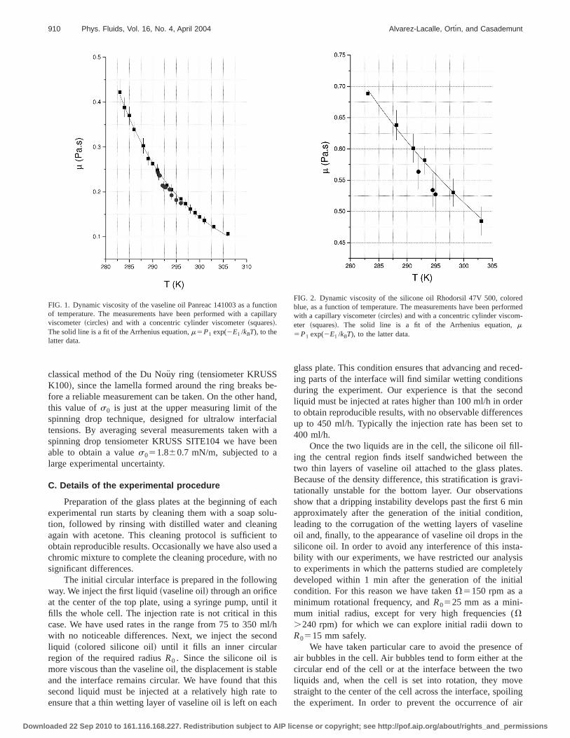
The vaseline oil used in the present experiments ismanufactured by Panreac~Ref. 141003!. The silicone oil ismanufactured by Rhodorsil~Ref. 47V 500!. Their nominaldensities at 20 °C arer15875610 kg/m3 for the vaseline oiland r25975610 kg/m3 for the silicone oil. Their dynamicviscosities have been measured at several temperatures witha concentric cylinder viscometer HAAKE RV20/CVB20Nand with a Cannon–Fenske capillary viscometer. The resultsare independent of the technique used within 5%, and areshown in Figs. 1 and 2.
Originally the two liquids are colorless. In order to ren-der the interface visible, the silicone oil has been coloredblue by dispersing into it a tiny amount of oil colorant manu-factured by Galloplast S.L. Dynamic viscometric measure-ments confirm that the liquid remains Newtonian after thecoloring process, and its viscosity is not significantly af-fected.
The interfacial tension between the two liquids,s0 , ison the order of 1 mN/m, typically 1 order of magnitudesmaller than the surface tension at an oil–air interface. Thisvalue makes it difficult to measures0 accurately. On the onehand, we have found it too small to be measured with the
909Phys. Fluids, Vol. 16, No. 4, April 2004 Low viscosity contrast fingering
Downloaded 22 Sep 2010 to 161.116.168.227. Redistribution subject to AIP license or copyright; see http://pof.aip.org/about/rights_and_permissions
classical method of the Du Nou¨y ring ~tensiometer KRUSSK100!, since the lamella formed around the ring breaks be-fore a reliable measurement can be taken. On the other hand,this value ofs0 is just at the upper measuring limit of thespinning drop technique, designed for ultralow interfacialtensions. By averaging several measurements taken with aspinning drop tensiometer KRUSS SITE104 we have beenable to obtain a values051.860.7 mN/m, subjected to alarge experimental uncertainty.
C. Details of the experimental procedure
Preparation of the glass plates at the beginning of eachexperimental run starts by cleaning them with a soap solu-tion, followed by rinsing with distilled water and cleaningagain with acetone. This cleaning protocol is sufficient toobtain reproducible results. Occasionally we have also used achromic mixture to complete the cleaning procedure, with nosignificant differences.
The initial circular interface is prepared in the followingway. We inject the first liquid~vaseline oil! through an orificeat the center of the top plate, using a syringe pump, until itfills the whole cell. The injection rate is not critical in thiscase. We have used rates in the range from 75 to 350 ml/hwith no noticeable differences. Next, we inject the secondliquid ~colored silicone oil! until it fills an inner circularregion of the required radiusR0 . Since the silicone oil ismore viscous than the vaseline oil, the displacement is stableand the interface remains circular. We have found that thissecond liquid must be injected at a relatively high rate toensure that a thin wetting layer of vaseline oil is left on each
glass plate. This condition ensures that advancing and reced-ing parts of the interface will find similar wetting conditionsduring the experiment. Our experience is that the secondliquid must be injected at rates higher than 100 ml/h in orderto obtain reproducible results, with no observable differencesup to 450 ml/h. Typically the injection rate has been set to400 ml/h.
Once the two liquids are in the cell, the silicone oil fill-ing the central region finds itself sandwiched between thetwo thin layers of vaseline oil attached to the glass plates.Because of the density difference, this stratification is gravi-tationally unstable for the bottom layer. Our observationsshow that a dripping instability develops past the first 6 minapproximately after the generation of the initial condition,leading to the corrugation of the wetting layers of vaselineoil and, finally, to the appearance of vaseline oil drops in thesilicone oil. In order to avoid any interference of this insta-bility with our experiments, we have restricted our analysisto experiments in which the patterns studied are completelydeveloped within 1 min after the generation of the initialcondition. For this reason we have takenV5150 rpm as aminimum rotational frequency, andR0525 mm as a mini-mum initial radius, except for very high frequencies (V.240 rpm) for which we can explore initial radii down toR0515 mm safely.
We have taken particular care to avoid the presence ofair bubbles in the cell. Air bubbles tend to form either at thecircular end of the cell or at the interface between the twoliquids and, when the cell is set into rotation, they movestraight to the center of the cell across the interface, spoilingthe experiment. In order to prevent the occurrence of air
FIG. 1. Dynamic viscosity of the vaseline oil Panreac 141003 as a functionof temperature. The measurements have been performed with a capillaryviscometer~circles! and with a concentric cylinder viscometer~squares!.The solid line is a fit of the Arrhenius equation,m5P1 exp(2E1 /kBT), to thelatter data.
FIG. 2. Dynamic viscosity of the silicone oil Rhodorsil 47V 500, coloredblue, as a function of temperature. The measurements have been performedwith a capillary viscometer~circles! and with a concentric cylinder viscom-eter ~squares!. The solid line is a fit of the Arrhenius equation,m5P1 exp(2E1 /kBT), to the latter data.
910 Phys. Fluids, Vol. 16, No. 4, April 2004 Alvarez-Lacalle, Ortın, and Casademunt
Downloaded 22 Sep 2010 to 161.116.168.227. Redistribution subject to AIP license or copyright; see http://pof.aip.org/about/rights_and_permissions

bubbles, the procedure for closing the cell is critical. Thisprocedure differs depending on the type of gap spacers used.
First, we have used six metallic spacers placed approxi-mately equispaced around the cell edge. In this case theplates are tightly clamped at these six points from the begin-ning. The air exits the cell freely while the liquids are beinginjected, until the injection of the second liquid is almostcomplete. Then the edge of the cell is closed with a rubberband, and the injection is interrupted. Air bubbles formedclose to the rubber band leave the cell thanks to the slightoverpressure created by the remaining liquid injection, whichthereafter is accommodated by the rubber band itself.
The closing procedure is different when the gap spacingis provided by an annular tefflon spacer. In this case, al-though the glass plates are loosely clamped to keep themaligned with the axis of rotation, we leave a free space be-tween the Teflon spacer and the top plate to evacuate the airdisplaced by the injection of the first liquid. Once this firstliquid reaches the Teflon spacer, injection is stopped. At thispoint it is usual to have air bubbles formed at the contact ofthe liquid with the tefflon spacer. In order to remove them,the cell is tightly clamped at six points, as before, and it is setto rotate until the air bubbles reach the central hole. Thebubbles are then withdrawn by producing a slight underpres-sure in the cell, which is compensated by the injection of thesecond liquid. Since this second injection must also be car-ried out with the cell tightly closed, to avoid the formation ofnew bubbles near the tefflon spacer, we restrict ourselves toinitial radii in the range 20,R0,50 mm in order to preventa significant deformation of the glass plates. Measurementsof the plate deflection with a mechanical strain–gauge showthat a nominal gap spacingb51.2 mm increases by about5% with the glass plates 10 mm thick, and by about 10%with the glass plates 7 mm thick.
Although the first closing procedure has the advantage ofnot producing any observable deformation of the glassplates, the second procedure is more efficient in preventingthe formation of air bubbles in the cell.
Our experiments have covered a large region of theavailable parameter space. We have explored values ofR0
~radii of the initial circular interface! in the range from 15 to85 mm, and rotational frequenciesV in the range from 150to 300 rpm. The values selected for the gap thicknessb havebeen 0.7060.04, 1.0060.05, and 1.3560.08 mm for themetallic spacers, and 1.2560.08 and 1.4060.12 mm for theannular Teflon spacer.
Combinations of these parameters have given rise to pat-terns with a number of fingers varying from 8 to 80. Produc-ing patterns with less than eight fingers is nearly impossiblein our conditions. It requires settingR0 andV to values toosmall to avoid dripping of one oil in the other, as explainedabove.
Since there is no control of the setup temperature, andthe viscosity of the liquids is highly sensitive to temperaturevariations ~Figs. 1 and 2!, the viscosity contrastA5(m2
2m1)/(m21m1) has been slightly different from one experi-ment to another, within the intervalA50.4– 0.5, followingthe variations in room temperature. It is known from numeri-cal simulations that a strong sensitivity of the fingering dy-
namics and morphology to the viscosity contrast is observedat values ofA close to 1, while no significant sensitivity toviscosity contrast is observed in the remaining interval oflower A.3,5,6
D. Qualitative description of the patterns
Once the initial condition has been prepared, the cell isset into motion. Figure 3 shows a temporal sequence of thepatterns obtained in a typical experiment.
There is first a latency periodt l , dependent on the pa-rameters of the experiment, in which the interface remainscircular. After this period the interface develops smallripples, at the onset of instability. The pattern formed is notperfectly symmetric, due to unavoidable randomness in theinitial condition, but it presents a regular arrangement of fin-gers of similar size.
The linear regime, in which the amplitude of the ripplesis smaller than or comparable to their lateral size, is veryshort. Very quickly the interface perturbations grow in time,both inwards ~vaseline displacing silicone! and outwards~silicone displacing vaseline!, giving rise to a characteristicfingering pattern.
One of the most remarkable features of the temporalevolution of this pattern is the absence of competition be-tween adjacent fingers of different sizes, in the sense that thenumber of growing fingers present in the linear regime is notmodified during the development of the pattern. This is best
FIG. 3. Snapshots of the pattern formation process in an experiment withb51.4 mm, R0541 mm, andV5210 rpm. The images are shown fromleft to right and from top to bottom.
911Phys. Fluids, Vol. 16, No. 4, April 2004 Low viscosity contrast fingering
Downloaded 22 Sep 2010 to 161.116.168.227. Redistribution subject to AIP license or copyright; see http://pof.aip.org/about/rights_and_permissions

visualized in the plot of the interface radius as a function ofthe polar angle shown in Fig. 4. Represented in this way, thepatterns show remarkable morphological similarities with thepatterns obtained in the channel geometry, both numerically3
and experimentally,4 in the limit of low viscosity contrast~except for the breaking of up–down symmetry!.
In our case, however, as the pattern goes into the deeplynonlinear regime, the fingers of silicone oil stretch and growfast outwards, while the fingers of vaseline oil nearly stop asthey approach the center of the cell. This asymmetric behav-ior is a purely geometrical effect not present in the channel
geometry. Figure 5 presents the sequence of patterns ob-tained in a second experiment, focusing on the nonlinear,latest stages of the dynamics.
A salient feature of our patterns is the strong tendency ofthe silicone fingers to pinch off, observed systematically inall experiments. Pinch-off follows the relatively fast stretch-ing of the longer outgrowing fingers, which evolve intoballoon-shaped fingers, with narrow filaments ending in awider, rounded droplet. The pinch-off takes place at the pointwhere the filament widens to form the droplet. A sequence ofpictures illustrating this characteristic behavior is presentedin Fig. 6. In some instances, provided that the filament ofsilicone oil receives enough flux from the cell center, apinch-off event is followed by a series of new pinch-offevents of the same finger, giving rise to a train of progres-sively smaller droplets, usually so small that can only beresolved once the cell is at rest.
After the pinch-off process, there is nearly no furtherdisplacement of the inner fluid outwards, and therefore nopossibility for the vaseline fingers to grow inwards. When allfingers have pinched, the system must reorganize itself tocontinue the emission of the inner, denser liquid. We haveobserved two main mechanisms for this, both shown in Fig.5: first, the reconnection of the incoming vaseline fingers,which results in a reduction of their number, and second theformation of new silicone fingers in the very late stages.These questions will be analyzed in detail in Sec. III F. Al-though the total amount of time for displacing most of the
FIG. 4. Polar representation of the interfaces shown in Fig. 3. The initialcondition is reproduced on each plot as a reference.
FIG. 5. Snapshots of the patterns obtained in an experiment withb51.25 mm,R0554 mm, andV5270 rpm, showing the latest stages of thepattern evolution. The images are shown from left to right and from top tobottom.
912 Phys. Fluids, Vol. 16, No. 4, April 2004 Alvarez-Lacalle, Ortın, and Casademunt
Downloaded 22 Sep 2010 to 161.116.168.227. Redistribution subject to AIP license or copyright; see http://pof.aip.org/about/rights_and_permissions

mass initially present in the inner layer never exceeds 5 min,it must be recognized that in the very late stages the patternis probably also affected by the corrugation of the wettinglayers coating the glass plates.
III. ANALYSIS AND DISCUSSION
A. Hele-Shaw equations
Navier–Stokes equation for the velocity field of a fluid,V, observed in a reference frame rotating with angular fre-quencyV, reads
] tV1~V•¹!V521
r¹p2V3~V3r !
22V3V1nDV, ~1!
wherer is the density of the fluid,p is the hydrostatic pres-sure field,r is the position of the fluid element measuredfrom the rotation axis, andn is the kinematic viscosity,n5m/r.
When this equation is particularized to a rotating Hele-Shaw cell withV5V z, inertial terms are much smaller thanviscous forces and pressure gradients, and the two terms onthe left hand side are negligible. Considering a Poiseuilleflow in the plane of the cell, and taking the average of thevelocity field in thez direction, we obtain8
v52b2
12m i¹S pi2
1
2r iV
2r 2D1b2
12m i2r iV z3v, ~2!
wherev is the average velocity in therf plane.
The contribution proportional toV2 arises from centrifu-gal forces, and the one proportional toV arises from Coriolisforces. The role of these two contributions has been demon-strated in numerical simulations of large viscosity contrastflows.8 Centrifugal forces tend to stretch an initially circulardroplet along the radial direction, producing elongated fin-gers which, due now to Coriolis forces, experiment a slightdeviation from purely radial growth in the counter directionof cell rotation.
Coriolis effects, however, are negligible in our experi-ments. This is best seen by considering the reciprocalEckman number introduced by Schwartz8
Re[b2
12m ir iV. ~3!
The largest value that Re takes in our experiments is Re.0.03, which corresponds to the largest gap thickness usedb51.4 mm, the largest angular frequency accessible in oursetup V5300 rpm, and the smallest kinematic viscositym/r5231024 m2/s. Since Re!1, the Coriolis term is just aperturbation of the velocity of relative magnitude 2Re, whichcan be safely neglected.
For typical experimental parameters Re.0.01, and thetypical radial velocity of well developed fingers isUr
.1 mm/s. Under these conditions, Coriolis forces wouldproduce tangential velocitiesUf.0.02 mm/s, which cannotbe resolved in the present experiments. For Coriolis effectsto be observable in our experimental setup, the kinematicviscosity of the fluids should be smaller by about 2 orders ofmagnitude. Water, for instance, would show chiral growthassociated with Coriolis forces even for narrow gaps and lowangular velocities.
Neglecting the Coriolis term in Eq.~2!, Darcy’s law canbe written as
vi5“f i , i 51,2 ~4!
with
f i52b2
12m iS pi2
1
2r iV
2r 2D , i 51,2. ~5!
The condition of incompressibility of the two liquids,“•v50, leads to the Laplace equation for the velocity po-tential in the bulk
Df i50. ~6!
To complete the set of equations for the free boundaryproblem in two dimensions, we must provide kinematic anddynamic boundary conditions at the interface. The twoboundary conditions considered usually are, first, the conti-nuity of the normal velocity at the interface
vn5n•“f15n•“f2 ~7!
and, second, a linear relation between the local pressurejump at the interface and its curvature
p22p15sk, ~8!
where s is the interfacial tension between the two liquidsand k is the local curvature of the interface~considered aone-dimensional line!.
FIG. 6. Sequence of pictures extracted from an experiment withb51.4 mm,R0537.5 mm, andV5180 rpm.
913Phys. Fluids, Vol. 16, No. 4, April 2004 Low viscosity contrast fingering
Downloaded 22 Sep 2010 to 161.116.168.227. Redistribution subject to AIP license or copyright; see http://pof.aip.org/about/rights_and_permissions

Although it has been often ignored in the literature, thislast equation is not strictly correct, particularly in the circulargeometry.14 Equation~8! actually comes from the quasistaticcondition of local mechanical equilibrium:
n•@t¢12t¢2#•n5sk, ~9!
wheret¢ is the local stress tensor. The effect of the normalvelocity gradients may be negligible in most situations in thechannel geometry, in particular in the linear regime, since thenormal velocity gradients give rise to higher order contribu-tions. Then the above condition reduces indeed to the usualone Eq.~8!. However, in a radial cell, normal velocity gra-dients on a circular interface do not vanish and the conditionleads to
p22p122~m2] rv r ,22m1] rv r ,1!5sk, ~10!
wherev r ,1 andv r ,2 are the radial components of the velocityfield in each of the two fluids. The additional terms in Eq.~10! will turn out to be relevant for our experiments, asshown later.
The boundary conditions specified above are a simplifi-cation of the real three-dimensional problem. In practice theinterface is a two-dimensional object with two local maincurvatures,k i andk' , in the directions parallel and perpen-dicular to the plane of the cell respectively. This gives rise toa number of complications:
~i! Depending on the wetting properties of the fluids andtheir relative velocity, the interface may either leave behindor absorb a liquid film on each glass plate. This modifies thebalance of mass at the interface and, consequently, the kine-matic boundary condition~7!.
~ii ! The thickness of the wetting films, and the dynamiccontact angle at the contact line of the interface with theglass plates, may be sensitively dependent on the interfacevelocity. As a result, the curvaturek' is not constant@asimplicitly assumed in Eq.~8!#, but a function of the localinterface velocity. This affects the dynamic boundary condi-tion ~8!.
These effects have been studied in detail in the channelgeometry, for air displacing a wetting liquid~viscosity con-trast A51). Park and Homsy15 proved that Eq.~8! shouldread
p22p15sF2
b1
p
4k iG ~11!
for Ca!1, where Ca is the capillary numbermV/s, with Vthe velocity of the interface. The next additional correction,derived by Schwartz,16 takes into account the influence of theviscous wetting film left on the plates as the interface moves
p22p15sF2
b1
p
4k iG1
2sJ
bCa2/3, ~12!
whereJ.3.8 in the formulation of Park and Homsy.A similar theoretical effort~including the extra stresses
from the velocity normal gradients! has not been carried outfor the radial geometry. To our knowledge, Maxworthy hasbeen the only author to consider kinetic corrections to theboundary conditions in experiments on this geometry, by as-
suming that the expressions valid in the channel geometrycould be directly translated to the radial geometry.17 In ourspecific case, however,Q50 and therefore the interface is atrest~in the reference frame rotating with the cell! at the onsetof the instability. Any corrections proportional to power lawsof the interface velocity will be correspondingly small. Thus,it is reasonable to assume that the dominant correction to thetwo-dimensional boundary conditions, in the linear regime,will come only from the influence of the wetting films on thecurvaturek' of the meniscus. Following the derivation ofPark and Homsy for the channel geometry,15 Eq. ~11!, thecorrection is simply a factorp/4 multiplying the surface ten-sion. Assuming that a similar correction would apply in ourcase, but eventually with a different numerical factor, weconclude that a convenient way to take three-dimensionaleffects into account, in the two-dimensional boundary condi-tions of our problem, is to considers in Eq. ~8! as an effec-tive interfacial tension, and leave it as a free parameter to bedetermineda posteriori. This is even more reasonable if werecall that the actual value ofs is itself subject to a largeexperimental uncertainty, as discussed in the previous sec-tion.
B. Linear stability analysis
First we make use of Eq.~8! as a dynamic boundarycondition. The linear dispersion relation of an initially circu-lar interface reads in this case9
v~n!5Vn2s
R03 n~n221!, ~13!
wherev(n) is the growth rate of an infinitesimal perturba-tion of the circular interface of the formdeinu ~moden), and
V5V2b2
12
r22r1
m21m1, s5
b2
12
s
m21m1. ~14!
In our caser2.r1 , making the centrifugal force destabiliz-ing for all modes, as expected. The interfacial tension doesnot affect the stability of the moden51 ~which preservesthe circular shape! but stabilizes all modesn.1. Finally,sinceQ50, the viscosity contrast does not play any role atthe linear level.
The fastest growing modenm and the marginal modenc
~separating unstable from stable modes! are given by
nm5A 13 ~11S!, nc5A11S. ~15!
Both depend on the parameterS5R03V/s, the ratio of cen-
trifugal to capillary forces, which plays the role of an inversedimensionless surface tension. Sinces is very small in ourexperiments, we haveS@1 in most experimental conditions.Then,nm andnc can be approximated by
nm.AS
3, nc.AS. ~16!
It is not difficult to show that, in this same limit, the growthrate of the fastest growing mode is given by
v~nm!5 23 nmv~1!. ~17!
914 Phys. Fluids, Vol. 16, No. 4, April 2004 Alvarez-Lacalle, Ortın, and Casademunt
Downloaded 22 Sep 2010 to 161.116.168.227. Redistribution subject to AIP license or copyright; see http://pof.aip.org/about/rights_and_permissions

When instead of Eq.~8! we consider Eq.~10! as theproper boundary condition the linear dispersion relationchanges to
v* ~n!51
111
6n~n2A!S b
R0D 2 F Vn2
s
R03 n~n221!G
.1
111
6n2e2
F Vn2s
R03 n3G , ~18!
wheree5b/R0 and the approximation is valid [email protected] dispersion relation differs from the previous one in theprefactor, that introduces a dependence on the gap spacingb.The correction is important only whenne;1, i.e., for modesof large wave numbern;R0 /b. While nc is not modified,the wave number of the fastest growing mode is now givenby
nm* 5A1
2FAS S1
18
e2D 2
1S24
e22S S118
e2D G5AS
3F11S e2
9D S
31O~e4S2!G . ~19!
The numbernm* coincides withnm except for a correctiondepending on the dimensionless parametere2S. This correc-tion results in larger wave numbers for larger gap spacings.
The low value of the interfacial tension in our experi-ments gives rise to a large number of fingers and makes thecorrection above non-negligible. On the other hand but forthe same reasonn@A, making the correction independent ofthe viscosity contrast.
C. Number of fingers emerging from the linearinstability
Since the growth of the unstable modes in the linearregime is exponential, it is reasonable to expect that the fast-est growing mode~as given by the maximum of the lineardispersion relation! determines the typical number of fingersformed at the onset of instability, provided that the noise issufficiently weak and uniformly distributed in all modes. Inexperiments, however, this is not quite the case and, since thebandwidth of unstable modes is large and the duration of thelinear regime is very short, the direct experimental verifica-tion of the linear dispersion relation is rather difficult.9,17,18
In the high-A limit, in addition, the nonlinear regime pre-sents a dynamic competition between neighbor fingers ofdiffering sizes, which results in a systematic reduction of thenumber of fingers present in the nonlinear regime.
Low-A flows, however, exhibit no competition betweenneighbor fingers, not only in the linear and weakly nonlinearregime but in the deeply nonlinear regime as well. This guar-antees that the wave number of the mode of largest ampli-tude at the end of the linear regime coincides with the num-ber of fingers observed in a given experiment. In summary,
the lack of finger competition makes low-A flows particu-larly suitable to check the predictions of a linear stabilityanalysis.
Figure 7 presents the number of fingers measured in ex-periments withb51.4 mm and different values ofR0 andV~allowing for the control parameterS to vary between 1500and 9000!, as a function ofS. In each experiment the numberof fingers has been determined at the beginning of the non-linear regime and, also, at the end of the nonlinear regimewhen the first droplets reach the cell edge. Both countingsnever differ by more than 5%. The difference is representedby the vertical error bars. The error bars forS, on the otherhand, reflect the experimental uncertainties inr1 , r2 , R0 ,and V, but not in the interfacial tensions. The solid linerunning through the experimental points is a fit of the formnm.AS/3, Eq. ~16!, in which s has been left as a fittingparameter. The fit givess51.960.1 mN/m.
Compared to previous analysis of the linear dispersionrelation,9,17,18 our experimental data show a remarkablysmall dispersion. This reflects the good reproducibility of theexperiments~the number of fingers formed in identical ex-perimental conditions is reproducible within less than 5%!,thanks to the absence of finger competition.
We must emphasize that the interfacial tension obtainedin the fit, although consistent with our experimental estima-tion of this parameter, does not necessarily coincide with theactual value ofs. First, we recall that wetting effects renor-malize s by an unknown factor~the factorp/4 in channelgeometry andA51), and second, it remains to be deter-mined whether the gap spacingb has an influence on theeffective value ofs, as predicted by Eq.~19!.
FIG. 7. ~Filled squares! Number of fingers measured in a series of experi-ments with gap spacingb51.4 mm and different values ofR0 andV, as afunction of the dimensionless parameterS. ~Solid line! Least-squares fit ofthe data to a functionnm.AS/3, giving an effective interfacial tensions51.9 mN/m.
915Phys. Fluids, Vol. 16, No. 4, April 2004 Low viscosity contrast fingering
Downloaded 22 Sep 2010 to 161.116.168.227. Redistribution subject to AIP license or copyright; see http://pof.aip.org/about/rights_and_permissions

We have addressed this second question by performingsimilar experiments with different gap spacings (b51.4, 1.0,and 0.7 mm!. The results are shown in Fig. 8, in which thenumber of fingers observed experimentally,N, is representedagainst the prediction fornm given by Eq.~16!. The solidsquares are the data forb51.4 mm presented already in Fig.7, and the straight line the corresponding fit withs51.9 mN/m. It is clear from the figure that the other datapoints are shifted systematically from the linear fit. The errorbars ~shown only for two points for clarity! reveal that thedeviation from the fit is not accidental. We conclude that avariation of the gap spacing seems to change the effectiveinterfacial tension in a systematic way.
This result can be accounted for by the modified dy-namic boundary condition~10! discussed in Sec. III A. Thisis demonstrated in Fig. 9, where the same data points arerepresented againstnm* , given by Eq.~19!, and are seen tocollapse in a single straight line corresponding to an effectiveinterfacial tensions51.4 mN/m. It becomes clear thatworking with two similar liquids makes the interfacial ten-sion very small, which favors a large number of fingers, sothat the small correction that leads tonm* is relevant in ourexperiments.
This analysis has provided us with an accurate value ofthe effective interfacial tension,s51.4 mN/m. In the casewhere we had a precise experimental determination of theactual interfacial tension, we would be able to determine thecorrection factor due to wetting effects. Currently we canonly mention that if we use the value measured by the spin-ning drop method,s51.8 mN/m, which is subject to a largeuncertainty, we get a correction factor very close top/4.
D. Empirical scaling of the patterns
An analysis7 of the Hele-Shaw equations presented inSec. III A shows that the experiments are controlled essen-
tially by two dimensionless parameters, the viscosity contrastA and the ratio of centrifugal to capillary forcesS. The firstof them~not varied in the present experiments! has no influ-ence on the linear regime, provided thatQ50, but plays animportant dynamic role in the nonlinear regime by control-ling finger competition. The second one determines thedominant wave number emerging from the linear regime,which remains dominant throughout the whole evolution forlow A-flows. On the other hand, our discussion about theappropriate dynamic boundary condition in the circular ge-ometry has shown that the gap spacing also plays a measur-able role in the linear regime and, thus, introduces a thirddimensionless groupe. The influence of this third parameterin the deeply nonlinear regime is more difficult to assess butwe do not expect it to be very significant.
The linear dispersion relation suggests a simple way tomake length and time dimensionless, usingR0 ~initial radius!and 1/v(1) @where v~1!, the growth rate of the moden51, is simply V], as the characteristic length and timescales.
In our experiments of high viscosity contrast flows9,14
this simple choice proved adequate to scale several measuresof the patterns, including the latency period before the devel-opment of the pattern, the radius of gyration of the pattern,the radial extent of the mixing zone, and others. This choice,however, did not provide a good scaling of the interfacestretching. This lack of scaling was attributed to the sensitiv-ity of interface stretching to capillary forces.
A natural way to introduce a dimensionless time scalethat takes into account the stabilizing role of the in-planesurface tensions is to replacet•v(1) by t•v(nm). Since,according to Eq. ~17!, v(nm);v(1)•nm , and nm
.(S/3)1/2, this new time scale introducesS ~the ratio ofcentrifugal to capillary forces! in the empirical scaling.
On the other hand, our study of the linear regime~Sec.III C ! has showed that replacingnm by nm* captures the slight
FIG. 8. ~Symbols! Number of fingers,N, measured in experiments withdifferent values ofR0 , V, and three gap spacingsb, against the number offingers predicted by the fastest growing mode of the linear dispersion rela-tion, nm.AS/3. The straight line reproduces the fit withs51.9 mN/mshown in Fig. 7.
FIG. 9. Data collapse of the measured number of fingers,N, achieved byplotting this number againstnm* @the number of fingers predicted by Eq.~19!# with an effective surface tensions51.4 mN/m.
916 Phys. Fluids, Vol. 16, No. 4, April 2004 Alvarez-Lacalle, Ortın, and Casademunt
Downloaded 22 Sep 2010 to 161.116.168.227. Redistribution subject to AIP license or copyright; see http://pof.aip.org/about/rights_and_permissions

dependence one introduced by the modified boundary con-dition ~10!. A suitable dimensionless time scale is thereforegiven by t•v(1)•nm* .
In order to make a quantitative characterization of thespatiotemporal evolution of the morphological instability, westudy in some detail the interface stretching, the latency timebefore the onset of instability, the radius of gyration of thepattern, and the mass of the droplets emitted by the radiallyoutgrowing fingers.
1. Latency period
The latency period,t l , is the time interval in which thecircular oil bubble~initial condition! remains circular, withinexperimental resolution, before the instability sets in and thepattern develops appreciably.
All measures of the pattern~such as the interface stretch-ing, the radius of gyration, etc.!, when plotted as a functionof time, remain constant duringt l , and then increase sharplyas the instability develops and the pattern enters the nonlin-ear regime.
In order to characterizet l , we consider in particular thetime evolution of the interface length in experiments withdifferent gap thickness, initial radius, and rotation frequency,reported in Fig. 10. The interface lengthL remains at itsinitial value 2pR0 for a period of time, increases sharply inthe linear regime, and then grows at a nearly constant rate inthe nonlinear regime. Our data points follow the interfacestretching until a first point of the interface reaches the celledge.t l is obtained by a backward extrapolation of this lastregime, thus measuring the time at which the instabilitywould have set in, had the interface length always grown atthe same rate.
Figure 11 presents the results of the latency time deter-
mined in this way, in the dimensionless formt l•v(1)•nm*versus the number of fingers formed in the experiment, rep-resented bynm* . We recall thatnm* depends on experimentalparameters through the two dimensionless groupsS, e. Thedata show that, within the large experimental uncertainties inthe determination of the latency time,t l•v(1)•nm* is practi-cally a constant (1262) for all the experiments considered.This observation is consistent with a scenario in which thenoise present in the initial condition has similar amplitudefor all possible modes and is sufficiently weak. This ensuresthat the fastest growing mode, whose growth rate is propor-tional to v(1)•nm* , has a much larger amplitude than anyother mode at the end of the linear regime, and is thereforethe first one to show up in the pattern.
A collapse of the latency time was also obtained for highviscosity contrast flows, but theret l•v(1) rather thant l
•v(1)•nm* was independent of the number of fingers.9 Thereason for the different behavior must be found in the differ-ent wetting conditions at the interface, since high viscositycontrast experiments were carried out in a dry~not prewet-ted! cell.
2. Interface stretching
The pronounced stretching of the interface presented inFig. 10 is represented in dimensionless variables,L/R0 ver-sus t•v(1), in Fig. 12. These variables do not produce acollapse of the different curves. Actually, the mean slope ofthe different curves in the sharp growth region can be seen todepend linearly on the number of fingers,N, as shown inFig. 13. The linear fit provides
Vs[1
R0 v~1!
dL
dt56013.2N. ~20!
The interpretation of this result is that the interface stretchingrate (Vs) follows two different time scales simultaneously.The independent term, 60, reflects a scaling oft with v(1),which is dominant for a small number of fingers—infrequent
FIG. 10. Interface stretching as a function of time, in a series of experimentswith different b, R0 , andV.
FIG. 11. Dimensionless latency time,t l•v(1)•nm* , as a function ofnm* , ina series of experiments with differentb, R0 , andV.
917Phys. Fluids, Vol. 16, No. 4, April 2004 Low viscosity contrast fingering
Downloaded 22 Sep 2010 to 161.116.168.227. Redistribution subject to AIP license or copyright; see http://pof.aip.org/about/rights_and_permissions

in our experiments. The term proportional toN reflects ascaling of t with v(1)•nm* , which is dominant for a largenumber of fingers.
The linear dependence onN in Eq. ~20! corresponds to ascenario in which:~i! all fingers grow simultaneously atroughly the same speed and~ii ! in the highly nonlinear re-
gime the contribution of a finger to the overall interfacelengthL comes basically from its two lateral, nearly parallelwalls; the contribution, therefore, is twice its radial size,measured from the beginning of the finger to the end of thedroplet. To verify this picture, we have measured directly thegrowth of the fingertips~radiusr ) in a large number of ex-periments. The experimental results~Fig. 14! show thatln(r/R0) grows linearly with (t2t0)•v(1) ~where t0 is thetime when the finger is formed!, and the slope is practicallyindependent of experimental parameters:a51.6060.15.Consequently, if we consider that the dominant contributionto the interface stretching is the stretching of the finger,which is particularly accurate when the number of fingers islarge enough, we haveL.2Nr.2NR0 exp@a(t2t0) v(1)#.2NR0@11a(t2t0) v(1)#, and thus
1
R0 v~1!
dL
dt.2anm* .3.2N, ~21!
in excellent agreement with the result of Eq.~20! deriveddirectly from the experiments for largeN.
From the former discussion it follows that, for largeN,the interface length should grow with a time scalet•v(1)•nm* . The corresponding data collapse is shown in Fig. 15.
The simple model of the evolution of the pattern out-lined in this section will be validated in forthcoming sectionsthrough other characterizations of the spatio-temporal dy-namics.
FIG. 12. Dimensionless interface stretching,L/R0 , as a function of dimen-sionless time,t•v(1), for theexperiments represented in Fig. 10.
FIG. 13. Dimensionless stretching rate,Vs , vs number of fingers,N. Thesolid line is a least-squares linear fit of the data.
FIG. 14. Plot of ln(r/R0) as a function of dimensionless timet•v(1). Theradial coordinater gives the distance of the silicone oil droplets to therotation axis. The average slope of the linear fits is 1.660.1.
918 Phys. Fluids, Vol. 16, No. 4, April 2004 Alvarez-Lacalle, Ortın, and Casademunt
Downloaded 22 Sep 2010 to 161.116.168.227. Redistribution subject to AIP license or copyright; see http://pof.aip.org/about/rights_and_permissions

3. Mass distribution
A different characterization of the morphological insta-bility, complementary of the interface stretching, is providedby its radial mass distribution. ‘‘Mass’’ refers here to thetwo-dimensional area covered by the pattern. The propertiesof this distribution are measured by the momentsRn , definedas
Rn5F*02pdf*0
r (f)r nr dr
*02pdf*0
r (f)r dr G1/n
n51,2,... . ~22!
The first moment is the average radius of the pattern. Thesecond moment of the distribution is the so called ‘‘radius ofgyration’’ Rg .
The time evolution ofRg for our set of experiments ispresented in Fig. 16. The overall picture shows a radius ofgyration that remains constant during the latency time, startsgrowing in the linear regime, and increases exponentially inthe nonlinear regime, until the droplets at the fingertips reachthe end of the cell and no more data are available.
We have verified that the proper time scale to collapsethe growth of the dimensionless radius of gyration,Rg /R0 ,is t•v(1). The collapse is shown in Fig. 17. Not surpris-ingly, the different curves are laterally displaced, since thetime scale of the latency time ist•v(1)•nm* .
The result presented in Fig. 17 can be understood in thesame scenario described above: all fingers grow simulta-neously, at a similar rate that scales witht•v(1). Making theassumption that the main contribution to the growth ofRg
comes from the droplet-shaped terminations of the fingers,and taking into account that there arenm* fingers, we con-clude that the mass carried by each finger and droplet mustbe inversely proportional to the number of fingers, forRg /R0
to scale witht•v(1) rather than witht•v(1)•nm* .This conclusion is consistent with the morphology of the
patterns~Fig. 3!, where we see that, in the mixing zone, thepattern is formed by an alternancy of outward-growing sili-cone fingers and inward-growing vaseline fingers, all ofsimilar width. Thus, the silicone fingers take up nearly thesame room in all the experiments, independently of the num-ber of growing fingers,nm* , each finger carrying an amountof fluid proportional to 1/nm* .
FIG. 15. Dimensionless interface stretching,L/R0 , as a function of dimen-sionless time,t•v(1)•nm* , for the experiments represented in Fig. 10.
FIG. 16. Radius of gyration of the patterns as a function of time.
FIG. 17. Dimensionless radius of gyration,Rg /R0 , as a function of dimen-sionless time,t•v(1).
919Phys. Fluids, Vol. 16, No. 4, April 2004 Low viscosity contrast fingering
Downloaded 22 Sep 2010 to 161.116.168.227. Redistribution subject to AIP license or copyright; see http://pof.aip.org/about/rights_and_permissions

Another consequence of this picture is that the totalamount of silicone oil displaced outwards~in the outgrowingfingers! will be a constant, irrespective of the initial radiusR0 . Only at small enoughR0 , when the overall amount ofsilicone oil is too small to provide for this constant value,should a cutoff to this behavior be expected. The implica-tions of this result on the size and overall mass of the drop-lets formed by finger pinchoff are discussed in the next sec-tion.
E. Mass of emitted drops
A typical sequence of the pinch-off process that givesrise to the release of a silicone oil droplet is shown in Fig. 6.We observe that the droplet at the fingertip widens as thefinger stretches into an elongated filament. This continueswhile the filament is wide enough to allow for the silicone oilto flow towards the tip. Close to pinch-off the filament isalready too thin for this. Finger pinch-off takes place at thejunction of the filament and the droplet. Given that beforeand after pinch-off, droplets are by large the main contribu-tion to the variation ofRg , the argument of the precedingsection means that the typical area of a droplet should beproportional to 1/nm* , wherenm* is the number of fingers inthe pattern. Accordingly, the overall area of all the dropletsshould be a constant, irrespective of the number of droplets.This is actually an average description, since not all dropletsin a given experiment are identical, and there is some disper-sion of their areas.
We have measured the total area covered by the firstgeneration of emitted droplets~the contribution of subse-quent generations is negligible! in a large collection of ex-periments with different experimental parameters (b,R0 ,V),giving rise to a wide distribution of numbers of fingers. Theresults are presented in Fig. 18, where the total area of thedroplets is plotted againstpR0
2, the area of the initial circle.The graph demonstrates clearly that the total area covered by
the droplets is essentially a constant, as predicted, rather thana fraction or some other function of the initial area. Thisconstancy holds above a finite thresholdR0c.35 mm(pR0c
2 .4000 mm2). We have not found a limit to this be-havior at large radii.
The threshold valueR0c.35 mm is consistent with thefact that the overall droplet area (A0.1200 mm2) wouldcorrespond to an initial circle of radiusR0.20 mm. Thus,for initial conditions withR0,20 mm the constancy of theoverall droplet area cannot hold. For 20 mm,R0,35 mmthe constant droplet area is not yet attained because the fin-gers also carry a fraction of the overall available area.
The large error bars in the plot reflect that the spatialresolution of our images is relatively low to measure the areaof droplets, since their radii fall in the range from 2 to 7 mm.The number of pixels on the droplet interface is comparableto the number of pixels within the droplet. The error barsaccount for the dispersion in droplet area after considering orneglecting the contribution of the droplet interface. Anothererror source is a slight~but detectable! increase of the dropletarea as the droplet velocity increases. This effect is due to thethickening of the vaseline films coating the two glass plates,above and below a silicone droplet, compressing the dropletin the vertical direction and expanding it in the horizontalplane. To minimize this error source we have measured thedroplet area well beyond pinch-off, when all droplets moveat roughly the same velocity.
The numerical valuesR0c.35 mm and droplet areaA0
51200 mm2 would presumably change if surface tensionand/or viscosity contrast were changed. Theoretical analysisand numerical simulations that we are currently performingshow that surface tension and viscosity contrast do play arole in the pinch-off process, e.g., in the time to pinch-offand in the mass flow through the filaments. Surface tensionand viscosity contrast may also have an influence on pinch-off through three-dimensional effects not considered in theHele-Shaw equations. This can modify the mass flow into thedroplets, thus changingA0 ~and henceR0c). We expect thischange to be small, however, since this flow is already lowwell before pinch-off takes place. Additional experimentswould be necessary to ascertain the relevance of these ef-fects.
F. The long-time regime after pinch-off
Once the silicone fingers experience the first generationof pinch-off, the dynamics of the patterns is substantiallymodified. After pinching, the silicone oil filaments, still con-nected to the central region, are too thin to allow for a sub-stantial outward flux of silicone oil. Thus, the pattern afterpinch-off is rather stable, and it takes a long time to displaceit outwards. The pattern must reorganize itself to emit theremaining silicone oil. We recall that the mechanisms for it,described in Sec. II D, are:~i! the generation of new siliconeoil fingers in a nonsystematic way and~ii ! the coalescence ofincoming vaseline oil fingers, which allows a region of sili-cone oil to become disconnected from the center and beemitted outwards. In the last stages of the pattern the vase-line fingers become considerably wide, and their number is
FIG. 18. Total area covered by the silicone oil droplets, after the first pinch-off process, vs the area covered by the initial condition. The solid line showsthe behavior expected if the two magnitudes were mutually proportional.
920 Phys. Fluids, Vol. 16, No. 4, April 2004 Alvarez-Lacalle, Ortın, and Casademunt
Downloaded 22 Sep 2010 to 161.116.168.227. Redistribution subject to AIP license or copyright; see http://pof.aip.org/about/rights_and_permissions

reduced dramatically down to values between two and fivefingers. They remain separated by rather thin silicone oilfilaments, which finally break up in many minute droplets.
With the purpose of making a characterization of thislong-time regime, we introduce the parameterFF(r ,t) ~fill-ing fraction! defined as
FF~r ,t !5*0
2r r 8dr8*02p f ~r 8,f!df
*0r r 8dr8*0
2pdf,
where
f ~r ,f!5H 1 silicone oil
0 vaseline oil .~23!
FF(r ,t) measures the ratio of the area occupied by the sili-cone oil to the total area, in a circle of radiusr at timet. Wefocus onFF(R0 ,t), corresponding to a circle defined by theinitial condition of the pattern. We study how the silicone oilinitially filling this circle is displaced outwards, particularlyat long times.
Figure 19 shows the evolution ofFF(R0 ,t) as a functionof the dimensionless timet•v(1) in different experiments.As usual, there is first a latency period in which the initialcondition is not modified, followed by the exponentialchange characteristic of the linear regime during a very shorttime, and then a decay associated with the nonlinear regime.This decay comprises two stages: one at a nearly constant
high rate, followed by another at much lower rate and punc-tuated by constantFF intervals~inset!, corresponding to thelong-time regime analyzed in this section.
The transition from one stage to the other, for one par-ticular experiment, is illustrated in the figure by two straightlines drawn to guide the eye. The transition is much moreabrupt in experiments with smallR0 and few fingers~15,say! than in experiments with largeR0 and many fingers~70,say!. There are two reasons for this: first, the mass emittedoutwards in the first stages of the nonlinear regime is roughlyconstant for all experiments, and therefore the experimentswith larger R0 have more silicone oil to emit in the laststages. Second, in the experiments with a larger number offingers the silicone oil fingers present an irregular, filament-like appearance, which favors the main mechanisms of sili-cone oil emission~reconnection of vaseline oil fingers, elon-gation of the silicone oil finger necks!. On the contrary, theexperiments with smallerR0 and few fingers present a moreregular arrangement in the mixing zone, with vaseline oilfingers clearly separated by silicone oil fingers. Being so,inner reconnection is not easy, nor is the elongation of sili-cone oil finger necks. These difficulties prevent the systemfrom displacing the silicone oil outwards, once the thickersilicone oil finger has pinched. Consequently, the rate atwhich FF(R0 ,t) decays is abruptly reduced.
Another interesting feature ofFF(R0 ,t) in the lateststages of the nonlinear regime is the presence of plateaus,i.e., periods where the filled fraction does not change appre-ciably, showing that there is no flux of silicone oil throughthe circumference of radiusR0 . The plateaus can be clearlyrecognized in the inset of Fig. 19. Their presence does notmean that the interface is frozen. Suppose that new fingershave been formed at timet, which account for the flux ofsilicone oil throughR0 at timet. A plateau starts when thesefingers, before pinching, become too narrow to allow for anyflux acrossR0 . Furthermore, immediately after the fingerspinching the filaments left behind relax, allowing no flux tocrossR0 until new fingers grow again from the radius theywere formed from and reach the radiusR0 .
In summary, the last stages of the highly nonlinear re-gime are particularly lengthy. The outward displacement ofthe silicone oil in these last stages relies on the asymmetriesof the pattern, and is dominated by the inner reconnection ofincoming vaseline fingers and the pinch-off of new outgoingsilicone fingers.
G. The role of low surface tension
Having a low viscosity contrast implies working withtwo liquids, which in our case results in a very low value ofthe interfacial tensions, about 1 order of magnitude smallerthan at an air–liquid interface. The question arises aswhether the dynamic and morphological features identifiedin our work are related only to the low viscosity contrast, orthe low interfacial tension plays also a relevant role. In thissense, it is important to note that the morphologies observedin the present experiments are remarkably similar to thoseobtained numerically for miscible flows~negligible interfa-cial tension! in a rotating Hele-Shaw cell.19
FIG. 19. The fraction of the initial circle filled with silicone oil,FF(R0 ,t),as a function of the dimensionless timet•v(1). The straight lines are drawnto help recognizing a change in the rate of silicone oil emission, in thenonlinear regime. The inset shows the presence of flat regions in the lateststages. The values ofb, V, andR are given in mm, rpm, and mm respec-tively.
921Phys. Fluids, Vol. 16, No. 4, April 2004 Low viscosity contrast fingering
Downloaded 22 Sep 2010 to 161.116.168.227. Redistribution subject to AIP license or copyright; see http://pof.aip.org/about/rights_and_permissions

Viscosity contrast and interfacial tension could be modi-fied nearly independently in channel geometry, by control-ling the temperature of a binary fluid mixture nearcriticality.4 Even though our current experimental setup doesnot allow us to work along this way, we will present hereaccurate numerical solutions of our flows that do provide adefinite answer to the question above—together with inter-esting additional information.
Figure 20 presents the results of two numerical experi-ments. The one on the left is forA50.4, S52500, and theone on the right forA50.4, S580. The same initial condi-tion has been used in both runs: a perfect circle perturbedwith 50 modes of 0.1% amplitude and random phases. Thenumerical algorithm is described in detail in Ref. 20.
The valueA50.4 has been chosen to match the viscositycontrast in the experiments. This value is representative oflow viscosity contrast flows because, as mentioned in Sec.II C, the fingering dynamics is sensitive toA only whenA isvery close to 1~around 0.9!, and practically insensitive toAin the remaining interval of lowerA.3,5,6We have performedthe same simulations forA50 and obtained numerical re-sults nearly identical to the ones presented in Fig. 20.
The point to stress is that the simulation presented in the
left panel of the figure, purposely designed to produce a largenumber of fingers, reproduces the basic features observed inour experiments:~i! All fingers formed in the early stages ofthe instability keep growing in the deeply nonlinear regime,demonstrating the absence of finger competition.~ii ! As inexperiments, the number of fingers matches the wave num-ber of the fastest growing mode in the linear dispersion re-lation, nm5A(11S)/3.29. ~iii ! Competition for space ofthe incoming fingers gives rise, in the later stages, to a typi-cal fork-like structure in which the tip of an outcoming fingerbifurcates in two new fingers.~iv! Droplets form at the fingerends, and characteristic signs of imminent pinch-off at thefinger–droplet junctions are visible, just before the code ishalted due to lack of accuracy.
It is worth noting that the same spatio-temporal evolu-tion of the interface~in dimensionless variables! is obtainedfor all sets of parameters compatible with given values ofA~viscosity contrast! andS ~inverse dimensionless surface ten-sion!, because these are the only two dimensionless param-eters of the problem forQ50.7 In particular, a modificationof the surface tension,s, has the only effect of changing thetime scale, if the other parameters of the flow are modified in
FIG. 20. Numerical integration of the spatiotemporalevolution of a circular drop. The three snapshots on theleft correspond toA50.4 andS52500, and the threesnapshots on the right toA50.4 andS580. The inter-
faces are shown at dimensionless timest 50,
231024, 4.431024 ~left!, and t 50, 2.531022, 3.731022 ~right!, measured in units of 12(m1
1m2)R03/(b2s).
922 Phys. Fluids, Vol. 16, No. 4, April 2004 Alvarez-Lacalle, Ortın, and Casademunt
Downloaded 22 Sep 2010 to 161.116.168.227. Redistribution subject to AIP license or copyright; see http://pof.aip.org/about/rights_and_permissions

such a way thatS remains unchanged. This means that theresults presented in Fig. 20 are representative of the dynam-ics for the A,S values reported, irrespective of the actualvalue of s, and therefore the features listed above are spe-cific of low viscosity contrast flows, and cannot be attributedto the low value ofs in the experiments.
A separate issue refers to the validity of the dynamicequations for extreme values of the physical parameters. Forinstance, a low value ofs may lead to morphological fea-tures on the scale of the cell thicknessb. Even with thisconcern in mind, the striking similarity with the numericalsimulations makes us confident that our experiments areproperly described by the Hele-Shaw equations.
In the right panel of Fig. 20 we show the spatio-temporalevolution for low viscosity contrast fingering~smallA) witha reduced number of fingers~small S). Let us recall thatthese patterns are not accessible in our experiments becauses is small andV must be kept relatively large for the insta-bility to develop before dripping in the vertical direction setsin. These simulations show again that fingers do not compete~they all keep growing!. In this case the absence of compe-tition cannot be attributed solely to the low viscosity con-trast, but predominantly to the increasing available space foroutgrowing fingers in the radial geometry. Nevertheless, nu-merical simulations in the channel geometry6 show the samelack of competition for similar number of fingers than thetwo sets of parameters of Fig. 20.
IV. SUMMARY AND CONCLUSIONS
We have conducted a systematic investigation of the dy-namics and morphology of the viscous fingering patternsformed in a rotating Hele-Shaw cell, due to the displacementof a lighter fluid by a denser fluid of comparable dynamicviscosity.
Working with two liquids has been found to be particu-larly involved and delicate. The liquids must be introduced inthe cell under well controlled conditions. When displaced bythe second liquid, the first liquid leaves a coating layer oneach glass plate whose thickness depends on the injectionrate during the preparation. The experiment must also becarried out before dripping of these coating layers sets in.Great care must also be put in avoiding air bubbles at theinterface between the two liquids.
The patterns obtained in our experiments make it evidentthat the condition of low viscosity contrast between the twoliquids suppresses the dynamic competition between fingers,characteristic of air–liquid displacements~high viscositycontrast!. The morphologies observed are strikingly differentfrom previous viscous fingering morphologies found in ra-dial geometry. Instead of being unstable against tip-splittingor side-branching, the fingers here stretch along the radialdirection and form a droplet at the tip, which usually de-taches from the finger through a pinch-off singularity.
The radial geometry imposes a modification of the usualYoung–Laplace boundary condition at the interface~pressurejump proportional to interface curvature!, which introduces adependence of the linear dispersion relation on gap spacing.We have presented experimental evidence that this effect is
relevant and measurable on displacements that involve alarge number of fingers. This is the most frequent situation inour experiments. The delicate scrutiny of the linear disper-sion relation required to verify this effect has been possiblethanks to the lack of dynamic competition between fingers,characteristic of low viscosity contrast displacements, whichallows us to equate the number of fingers in the nonlinearregime to the fastest growing wave number in the linear re-gime.
Concerning the empirical scaling of different character-istic measures of the patterns, we have found that most mea-sures follow the time scalet•v(1), but theinterface stretch-ing follows the time scalet•v(1)•nm* , which introduces thenumberS ~ratio of centrifugal to capillary forces! in the scal-ing. The same happened also for high viscosity contrastdisplacements.9 Nevertheless, one must be careful in drawingconclusions from the comparison between our experimentsand those of Ref. 9~for high viscosity contrast!, because thelatter were carried out in a dry cell, and hence under verydifferent wetting conditions. By comparing experimental re-sults to numerical simulations of air–oil displacements, wehave found that the Hele-Shaw equations reproduce only theexperiments of oil displacing air when the cell has beenprewetted. Wetting conditions play a determinant role in thepattern morphologies, and may also be relevant in the scalingof the different measures. This issue will be addressed in aforthcoming work.
The problem of finger pinch-off and the formation ofdroplets is interesting for a variety of reasons. Pinch-offseems to be favored by the low viscosity contrast and by therotation of the cell~since centrifugal pressure increases lin-early with radial distance to the rotation axis!. But the ques-tion remains whether the finite-time pinch-off observed inour experiments is only a three-dimensional effect not con-tained in the two-dimensional Hele-Shaw equations~whichcould lead to pinch-off at infinite time! or, on the contrary,the two-dimensional model can lead spontaneously to finite-time pinch-off. The question cannot be answered experimen-tally, since in experiments the three-dimensional structure ofthe meniscus shows up unavoidably near pinch-off, as soonas the width of a finger becomes comparable to the gap spac-ing b. The interplay between viscosity contrast and rotationin the possible existence of finite-time singularities in thetwo-dimensional Hele-Shaw equations is an interesting openquestion.
ACKNOWLEDGMENTS
We are grateful to Ll. Carrillo and E. Paune´ for enlight-ening discussions. The technical support of M. Castro, M.del Rıo, J. Llorens ~Servei de Reologia, UB!, and F.Comelles~IIQA, CSIC!, is greatly appreciated. This researchis partially supported by the DGES~Spain!, Project No.BXX-2000-0638-C02-02, the European Commission throughNetwork No. HPRN-CT-2002-00312, and by the DURSI~Generalitat de Catalunya!, Project No. 2001-SGR-00433.E.A.L. and J.O. acknowledge additional financial supportfrom the DURSI.
923Phys. Fluids, Vol. 16, No. 4, April 2004 Low viscosity contrast fingering
Downloaded 22 Sep 2010 to 161.116.168.227. Redistribution subject to AIP license or copyright; see http://pof.aip.org/about/rights_and_permissions

1M. C. Cross and P. C. Hohenberg, ‘‘Pattern formation outside of equilib-rium,’’ Rev. Mod. Phys.65, 851 ~1993!.
2P. Pelce´, Dynamics of Curved Fronts, Perspectives in Physics~Academic,San Diego, CA, 1988!.
3G. Tryggvason and H. Aref, ‘‘Numerical experiments on Hele-Shaw flowwith a sharp interface,’’ J. Fluid Mech.136, 1 ~1983!; ‘‘Fingering interac-tion mechanism in stratified Hele-Shaw flow,’’154, 287 ~1985!; J. Casa-demunt, D. Jasnow, and A. Herna´ndez-Machado, ‘‘Interface equation andviscosity contrast in Hele-Shaw flow,’’ Int. J. Mod. Phys. B6, 1647~1992!.
4J. V. Maher, ‘‘Development of viscous fingering patterns,’’ Phys. Rev. Lett.54, 1498~1985!; M. W. DiFrancesco and J. V. Maher, ‘‘Noisy and regularfeatures in Saffman–Taylor patterns,’’ Phys. Rev. A39, 4709 ~1989!;‘‘Hele-Shaw scaling properties of low contrast Saffman–Taylor flows,’’40, 295 ~1989!; H. Zhao and J. V. Maher, ‘‘Viscous fingering experimentswith periodic boundary conditions,’’ibid. 42, 5894~1990!.
5J. Casademunt and D. Jasnow, ‘‘Defects dynamics in viscous fingering,’’Phys. Rev. Lett.67, 3677~1991!; ‘‘Finger competition and viscosity con-trast in viscous fingering. A topological approach,’’ Physica D79, 387~1994!.
6E. Paune´, ‘‘Interface dynamics in two-dimensional viscous flows,’’ Ph.D.thesis, University of Barcelona, Barcelona, Spain, 2002.
7E. Alvarez-Lacalle, J. Casademunt, and J. Ortı´n, ‘‘Systematic weakly non-linear analysis of interfacial instabilities in Hele-Shaw flows,’’ Phys. Rev.E 64, 016302 ~2001!; ‘‘Systematic weakly nonlinear analysis of radialviscous fingering,’’68, 026308~2003!.
8L. W. Schwartz, ‘‘Instabilities and fingering in a rotating Hele-Shaw cell orporous medium,’’ Phys. Fluids A1, 167 ~1989!.
9Ll. Carrillo, F. X. Magdaleno, J. Casademunt, and J. Ortı´n, ‘‘Experiments
in a rotating Hele-Shaw cell,’’ Phys. Rev. E54, 6260~1996!.10V. M. Entov, P. I. Etingof, and D. Ya. Kleinbock, ‘‘On nonlinear interface
dynamics in Hele-Shaw flows,’’ Eur. J. Appl. Math.6, 399 ~1996!.11D. Crowdy, ‘‘Theory of exact solutions for the evolution of a fluid annulus
in a rotating Hele-Shaw cell,’’ Q. Appl. Math.60, 11 ~2002!; ‘‘On a classof geometry-driven free boundary problems,’’ SIAM~Soc. Ind. Appl.Math.! J. Appl. Math.62, 945 ~2001!.
12F. X. Magdaleno, A. Rocco, and J. Casademunt, ‘‘Interface dynamics inHele-Shaw flows with centrifugal forces: Preventing cusp singularitieswith rotation,’’ Phys. Rev. E62, R5887~2000!.
13Ll. Carrillo, J. Soriano, and J. Ortı´n, ‘‘Radial displacement of a fluidannulus in a rotating Hele-Shaw cell,’’ Phys. Fluids11, 778 ~1999!; ‘‘In-terfacial instabilities of a fluid annulus in a rotating Hele-Shaw cell,’’12,1685 ~2000!.
14Ll. Carrillo, ‘‘Estudio experimental de sistemas fuera del equilibrio,’’Ph.D. thesis, University of Barcelona, Barcelona, Spain, 2000.
15C. W. Park and G. M. Homsy, ‘‘Two-phase displacements in Hele-Shawcells: Theory,’’ J. Fluid Mech.139, 291 ~1984!.
16L. Schwartz, ‘‘Stability of Hele-Shaw flows: The wetting-layer effect,’’Phys. Fluids29, 3086~1986!.
17T. Maxworthy, ‘‘Experimental study of interface instability in a Hele-Shaw cell,’’ Phys. Rev. A39, 5863~1989!.
18K. V. McCloud and J. V. Maher, ‘‘Experimental perturbation to Saffman–Taylor flow,’’ Phys. Rep.260, 139 ~1995!.
19C.-Y. Chen and S.-W. Wang, ‘‘Interfacial instabilities of miscible fluids ina rotating Hele-Shaw cell,’’ Fluid Dyn. Res.30, 315 ~2002!.
20E. Paune´, M. Siegel, and J. Casademunt, ‘‘Effects of small surface tensionin Hele-Shaw multifinger dynamics: An analytical and numerical study,’’Phys. Rev. E66, 046205~2002!.
924 Phys. Fluids, Vol. 16, No. 4, April 2004 Alvarez-Lacalle, Ortın, and Casademunt
Downloaded 22 Sep 2010 to 161.116.168.227. Redistribution subject to AIP license or copyright; see http://pof.aip.org/about/rights_and_permissions