low voltage alternators - 4 pole - leroy-somerlow voltage alternators - 4 pole tal a46 - tal a47 -...
TRANSCRIPT

Low Voltage Alternators - 4 pole
TAL A46 - TAL A47 - TAL A49180 to 1000 kVA - 50 Hz / 225 to 1250 kVA - 60 Hz
Electrical and Mechanical data
2 Leroy-Somer Electric Power Generation
Low Voltage Alternators - 4 poleTALA46 - TALA47 - TALA49
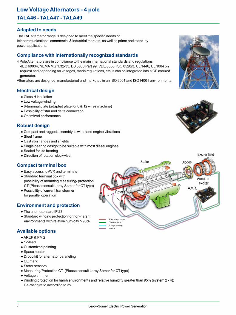
Adapted to needsThe TAL alternator range is designed to meet the specific needs of telecommunications, commercial & industrial markets, as well as prime and stand-by power applications.
Compliance with internationally recognized standards4 Pole Altemators are in compliance to the main international standards and regulations:
-IEC 60034, NEMA MG 1.32-33, BS 5000 Part 99, VDE 0530, ISO 8528/3, UL 1446, UL 1004 onrequest and depending on voltages, marin regulations, etc. It can be integrated into a CE markedgenerator.
Alternators are designed, manufactured and marketed in an ISO 9001 and ISO14001 environments.
Electrical design ● Class H insulation ● Low voltage winding ● 6-terminal plate (adapted plate for 6 & 12 wires machine) ● Possibility of star and delta connection ● Optimized performance
Robust design ● Compact and rugged assembly to withstand engine vibrations ● Steel frame ● Cast iron flanges and shields ● Single bearing design to be suitable with most diesel engines ● Sealed for life bearing ● Direction of rotation clockwise
Compact terminal box ● Easy access to AVR and terminals ● Standard terminal box with possibility of mounting Measuring/ protection CT (Please consult Leroy Somer for CT type) ● Possibility of current transformer for parallel operation
Environment and protection ● The alternators are IP 23 ● Standard winding protection for non-harsh environments with relative humidity ≤ 95%
Available options ● AREP & PMG ● 12-lead ● Customized painting ● Space heater ● Droop kit for alternator paralleling ● CE mark ● Stator sensors ● Measuring/Protection CT (Please consult Leroy Somer for CT type) ● Voltage trimmer ● Winding protection for harsh environments and relative humidity greater than 95% (system 2 - 4): De-rating ratio according to 3%
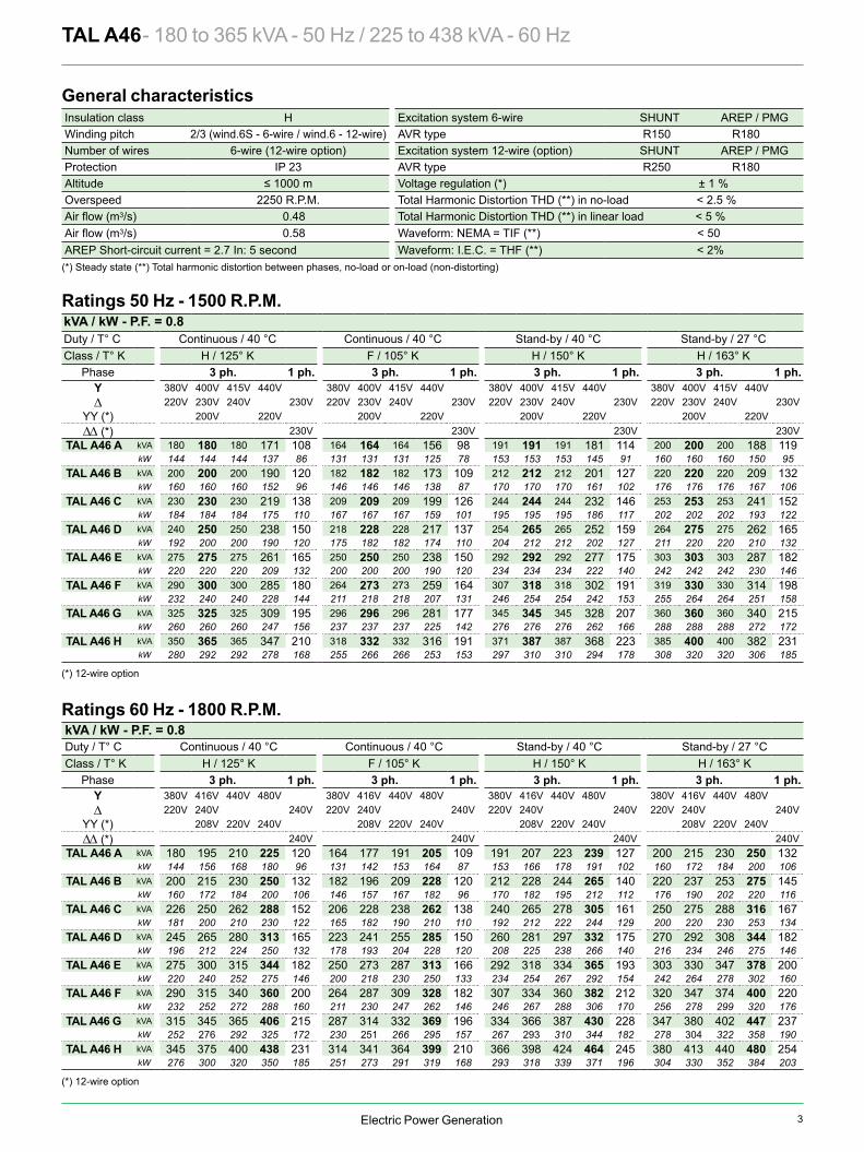
A.V.R.
Exciter field
Armatureexciter
DiodesStator
Rotor
Alternating currentDirect currentVoltage sensingNeutral
3Electric Power Generation
Phase 3 ph. 1 ph. 3 ph. 1 ph. 3 ph. 1 ph. 3 ph. 1 ph.Y 380V 400V 415V 440V 380V 400V 415V 440V 380V 400V 415V 440V 380V 400V 415V 440V∆ 220V 230V 240V 230V 220V 230V 240V 230V 220V 230V 240V 230V 220V 230V 240V 230V
YY (*) 200V 220V 200V 220V 200V 220V 200V 220V∆∆ (*) 230V 230V 230V 230V
TAL A46 A kVA 180 180 180 171 108 164 164 164 156 98 191 191 191 181 114 200 200 200 188 119kW 144 144 144 137 86 131 131 131 125 78 153 153 153 145 91 160 160 160 150 95
TAL A46 B kVA 200 200 200 190 120 182 182 182 173 109 212 212 212 201 127 220 220 220 209 132kW 160 160 160 152 96 146 146 146 138 87 170 170 170 161 102 176 176 176 167 106
TAL A46 C kVA 230 230 230 219 138 209 209 209 199 126 244 244 244 232 146 253 253 253 241 152kW 184 184 184 175 110 167 167 167 159 101 195 195 195 186 117 202 202 202 193 122
TAL A46 D kVA 240 250 250 238 150 218 228 228 217 137 254 265 265 252 159 264 275 275 262 165kW 192 200 200 190 120 175 182 182 174 110 204 212 212 202 127 211 220 220 210 132
TAL A46 E kVA 275 275 275 261 165 250 250 250 238 150 292 292 292 277 175 303 303 303 287 182kW 220 220 220 209 132 200 200 200 190 120 234 234 234 222 140 242 242 242 230 146
TAL A46 F kVA 290 300 300 285 180 264 273 273 259 164 307 318 318 302 191 319 330 330 314 198kW 232 240 240 228 144 211 218 218 207 131 246 254 254 242 153 255 264 264 251 158
TAL A46 G kVA 325 325 325 309 195 296 296 296 281 177 345 345 345 328 207 360 360 360 340 215kW 260 260 260 247 156 237 237 237 225 142 276 276 276 262 166 288 288 288 272 172
TAL A46 H kVA 350 365 365 347 210 318 332 332 316 191 371 387 387 368 223 385 400 400 382 231kW 280 292 292 278 168 255 266 266 253 153 297 310 310 294 178 308 320 320 306 185
Phase 3 ph. 1 ph. 3 ph. 1 ph. 3 ph. 1 ph. 3 ph. 1 ph.Y 380V 416V 440V 480V 380V 416V 440V 480V 380V 416V 440V 480V 380V 416V 440V 480V∆ 220V 240V 240V 220V 240V 240V 220V 240V 240V 220V 240V 240V
YY (*) 208V 220V 240V 208V 220V 240V 208V 220V 240V 208V 220V 240V∆∆ (*) 240V 240V 240V 240V
TAL A46 A kVA 180 195 210 225 120 164 177 191 205 109 191 207 223 239 127 200 215 230 250 132kW 144 156 168 180 96 131 142 153 164 87 153 166 178 191 102 160 172 184 200 106
TAL A46 B kVA 200 215 230 250 132 182 196 209 228 120 212 228 244 265 140 220 237 253 275 145kW 160 172 184 200 106 146 157 167 182 96 170 182 195 212 112 176 190 202 220 116
TAL A46 C kVA 226 250 262 288 152 206 228 238 262 138 240 265 278 305 161 250 275 288 316 167kW 181 200 210 230 122 165 182 190 210 110 192 212 222 244 129 200 220 230 253 134
TAL A46 D kVA 245 265 280 313 165 223 241 255 285 150 260 281 297 332 175 270 292 308 344 182kW 196 212 224 250 132 178 193 204 228 120 208 225 238 266 140 216 234 246 275 146
TAL A46 E kVA 275 300 315 344 182 250 273 287 313 166 292 318 334 365 193 303 330 347 378 200kW 220 240 252 275 146 200 218 230 250 133 234 254 267 292 154 242 264 278 302 160
TAL A46 F kVA 290 315 340 360 200 264 287 309 328 182 307 334 360 382 212 320 347 374 400 220kW 232 252 272 288 160 211 230 247 262 146 246 267 288 306 170 256 278 299 320 176
TAL A46 G kVA 315 345 365 406 215 287 314 332 369 196 334 366 387 430 228 347 380 402 447 237kW 252 276 292 325 172 230 251 266 295 157 267 293 310 344 182 278 304 322 358 190
TAL A46 H kVA 345 375 400 438 231 314 341 364 399 210 366 398 424 464 245 380 413 440 480 254kW 276 300 320 350 185 251 273 291 319 168 293 318 339 371 196 304 330 352 384 203
TAL A46 - 180 to 365 kVA - 50 Hz / 225 to 438 kVA - 60 Hz General characteristicsInsulation class H Excitation system 6-wire SHUNT AREP / PMGWinding pitch 2/3 (wind.6S - 6-wire / wind.6 - 12-wire) AVR type R150 R180Number of wires 6-wire (12-wire option) Excitation system 12-wire (option) SHUNT AREP / PMGProtection IP 23 AVR type R250 R180Altitude ≤ 1000 m Voltage regulation (*) ± 1 %Overspeed 2250 R.P.M. Total Harmonic Distortion THD (**) in no-load < 2.5 %
3/s) 0.48 Total Harmonic Distortion THD (**) in linear load < 5 %3/s) 0.58 Waveform: NEMA = TIF (**) < 50
AREP Short-circuit current = 2.7 In: 5 second Waveform: I.E.C. = THF (**) < 2%(*) Steady state (**) Total harmonic distortion between phases, no-load or on-load (non-distorting)
kVA / kW - P.F. = 0.8Duty / T° C Continuous / 40 °C Continuous / 40 °C Stand-by / 40 °C Stand-by / 27 °CClass / T° K H / 125° K F / 105° K H / 150° K H / 163° K
Ratings 50 Hz - 1500 R.P.M.
kVA / kW - P.F. = 0.8Duty / T° C Continuous / 40 °C Continuous / 40 °C Stand-by / 40 °C Stand-by / 27 °CClass / T° K H / 125° K F / 105° K H / 150° K H / 163° K
Ratings 60 Hz - 1800 R.P.M.
(*) 12-wire option
(*) 12-wire option
C
M
Y
CM
MY
CY
CMY
K
TALA46 5675b_en.pdf 1 2019/1/9 17:58:50

4 Electric Power Generation
93.193.494.094.192.4
95.495.695.895.5
93.4
85.0
90.0
95.0
100.0
0 50 100 150 200 250 300 350 400 450
90.991.392.493.0
91.8
94.094.394.894.8
93.0
85.0
90.0
95.0
100.0
0 50 100 150 200 250 300
91.391.792.693.0
91.4
94.294.594.994.7
92.6
85.0
90.0
95.0
100.0
0 50 100 150 200 250 300
90.991.492.392.7
91.1
94.094.294.694.5
92.3
85.0
90.0
95.0
100.0
0 50 100 150 200 250
91.491.892.592.7
90.6
94.294.494.794.4
91.8
85.0
90.0
95.0
100.0
0 50 100 150 200 250
92.793.093.693.8
91.9
95.295.395.595.2
92.9
85.0
90.0
95.0
100.0
0 50 100 150 200 250 300 350 400
91.992.393.193.5
91.9
94.794.995.395.1
93.1
85.0
90.0
95.0
100.0
0 50 100 150 200 250 300 350
91.892.293.093.4
92.0
94.694.895.295.1
93.1
85.0
90.0
95.0
100.0
0 50 100 150 200 250 300 350
TAL A46 E
TAL A46 F
TAL A46 C TAL A46 G
TAL A46 D TAL A46 H
TAL A46 A
TAL A46 B
A B C D E F G HKcc 0.39 0.35 0.37 0.34 0.37 0.4 0.45 0.43Xd 313 348 340 370 347 335 297 303Xq 159 177 173 188 177 171 151 154
T’do 1956 1956 1983 1983 2018 2033 2072 2093X’d 16 17.7 17.1 18.6 17.1 16.5 14.3 14.5T’d 100 100 100 100 100 100 100 100X”d 12.8 14.2 13.7 14.9 13.7 13.2 11.4 11.6T”d 10 10 10 10 10 10 10 10X”q 16.4 18.2 17.4 18.9 17.2 16.4 14.1 14.2Xo 0.66 0.74 0.71 0.77 0.71 0.68 0.59 0.6X2 14.6 16.2 15.6 16.9 15.5 14.8 12.8 12.9Ta 15 15 15 15 15 15 15 15
io (A) 0.95 0.95 1.01 1.01 1.1 1.1 1.06 1.06ic (A) 3.4 3.72 3.84 4.14 3.99 3.64 3.63 3.63uc (V) 48 52.4 37.4 40.2 55.6 46.2 42.1 41.9
ms 500 500 500 500 500 500 500 500kVA 311 311 372 371 444 445 556 618kVA 374 376 446 447 533 534 667 741% 17.1 18.4 18 19.1 18 19.1 17.4 17.4% 15.1 16.2 15.8 16.8 16.2 17.2 17.3 15.4W 2977 2977 3297 3297 3625 4013 4541 4750W 12841 15040 16562 18869 18504 19800 19303 20484
TAL A46 - 180 to 365 kVA - 50 Hz / 225 to 438 kVA - 60 Hz
— P.F.: 0.8) (...... P.F.: 1)
Short-circuit ratioDirect-axis synchro. reactance unsaturatedQuadrature-axis synchro. reactance unsaturatedNo-load transient time constantDirect-axis transient reactance saturatedShort-circuit transient time constantDirect-axis subtransient reactance saturatedSubtransient time constantQuadrature-axis subtransient reactance saturatedZero sequence reactanceNegative sequence reactance saturatedArmature time constant
Other class H / 400 V dataNo-load excitation current SHUNT/AREPOn-load excitation current SHUNT/AREPOn-load excitation voltage SHUNT/AREPResponse time (∆U = 20% transient)Start (∆U = 20% cont. or ∆U = 30% trans.) SHUNT*Start (∆U = 20% cont. or ∆U = 30% trans.) AREP*Transient ∆U (on-load 4/4) SHUNT - P.F.: 0.8 LAG
Transient ∆U (on-load 4/4) AREP - P.F.: 0.8 LAG
No-load lossesHeat dissipation
Reactances (%). Time constants (ms) - Class H / 400 V
* P.F. = 0.6
C
M
Y
CM
MY
CY
CMY
K
TALA46 5675b_en.pdf 1 2019/1/9 17:59:07
5Electric Power Generation
93.193.494.094.192.4
95.495.695.895.5
93.4
85.0
90.0
95.0
100.0
0 50 100 150 200 250 300 350 400 450
90.991.392.493.0
91.8
94.094.394.894.8
93.0
85.0
90.0
95.0
100.0
0 50 100 150 200 250 300
91.391.792.693.0
91.4
94.294.594.994.7
92.6
85.0
90.0
95.0
100.0
0 50 100 150 200 250 300
90.991.492.392.7
91.1
94.094.294.694.5
92.3
85.0
90.0
95.0
100.0
0 50 100 150 200 250
91.491.892.592.7
90.6
94.294.494.794.4
91.8
85.0
90.0
95.0
100.0
0 50 100 150 200 250
92.793.093.693.8
91.9
95.295.395.595.2
92.9
85.0
90.0
95.0
100.0
0 50 100 150 200 250 300 350 400
91.992.393.193.5
91.9
94.794.995.395.1
93.1
85.0
90.0
95.0
100.0
0 50 100 150 200 250 300 350
91.892.293.093.4
92.0
94.694.895.295.1
93.1
85.0
90.0
95.0
100.0
0 50 100 150 200 250 300 350
TAL A46 E
TAL A46 F
TAL A46 C TAL A46 G
TAL A46 D TAL A46 H
TAL A46 A
TAL A46 B
A B C D E F G HKcc 0.39 0.35 0.37 0.34 0.37 0.4 0.45 0.43Xd 313 348 340 370 347 335 297 303Xq 159 177 173 188 177 171 151 154
T’do 1956 1956 1983 1983 2018 2033 2072 2093X’d 16 17.7 17.1 18.6 17.1 16.5 14.3 14.5T’d 100 100 100 100 100 100 100 100X”d 12.8 14.2 13.7 14.9 13.7 13.2 11.4 11.6T”d 10 10 10 10 10 10 10 10X”q 16.4 18.2 17.4 18.9 17.2 16.4 14.1 14.2Xo 0.66 0.74 0.71 0.77 0.71 0.68 0.59 0.6X2 14.6 16.2 15.6 16.9 15.5 14.8 12.8 12.9Ta 15 15 15 15 15 15 15 15
io (A) 0.95 0.95 1.01 1.01 1.1 1.1 1.06 1.06ic (A) 3.4 3.72 3.84 4.14 3.99 3.64 3.63 3.63uc (V) 48 52.4 37.4 40.2 55.6 46.2 42.1 41.9
ms 500 500 500 500 500 500 500 500kVA 311 311 372 371 444 445 556 618kVA 374 376 446 447 533 534 667 741% 17.1 18.4 18 19.1 18 19.1 17.4 17.4% 15.1 16.2 15.8 16.8 16.2 17.2 17.3 15.4W 2977 2977 3297 3297 3625 4013 4541 4750W 12841 15040 16562 18869 18504 19800 19303 20484
TAL A46 - 180 to 365 kVA - 50 Hz / 225 to 438 kVA - 60 Hz
— P.F.: 0.8) (...... P.F.: 1)
Short-circuit ratioDirect-axis synchro. reactance unsaturatedQuadrature-axis synchro. reactance unsaturatedNo-load transient time constantDirect-axis transient reactance saturatedShort-circuit transient time constantDirect-axis subtransient reactance saturatedSubtransient time constantQuadrature-axis subtransient reactance saturatedZero sequence reactanceNegative sequence reactance saturatedArmature time constant
Other class H / 400 V dataNo-load excitation current SHUNT/AREPOn-load excitation current SHUNT/AREPOn-load excitation voltage SHUNT/AREPResponse time (∆U = 20% transient)Start (∆U = 20% cont. or ∆U = 30% trans.) SHUNT*Start (∆U = 20% cont. or ∆U = 30% trans.) AREP*Transient ∆U (on-load 4/4) SHUNT - P.F.: 0.8 LAG
Transient ∆U (on-load 4/4) AREP - P.F.: 0.8 LAG
No-load lossesHeat dissipation
Reactances (%). Time constants (ms) - Class H / 400 V
* P.F. = 0.6
C
M
Y
CM
MY
CY
CMY
K
TALA46 5675b_en.pdf 1 2019/1/9 17:59:07
Electric Power Generation
0%
5%
10%
15%
20%
25%
30%
0 100 200 300 400 500 600 700 800 900
0%
5%
10%
15%
20%
25%
30%
0 100 200 300 400 500 600 700 800 900
0%
5%
10%
15%
20%
25%
30%
0 100 200 300 400 500 600 700 800 900
0%
5%
10%
15%
20%
25%
30%
0 100 200 300 400 500 600 700 800 900
0%
5%
10%
15%
20%
25%
30%
0 100 200 300 400 500 600 700 800 900
0%
5%
10%
15%
20%
25%
30%
0 100 200 300 400 500 600 700 800 900
A B C E G HD F
A B C E G HD F A B C E G HD F
A B C E G HD F A B C E G HD F
A B C E G HD F
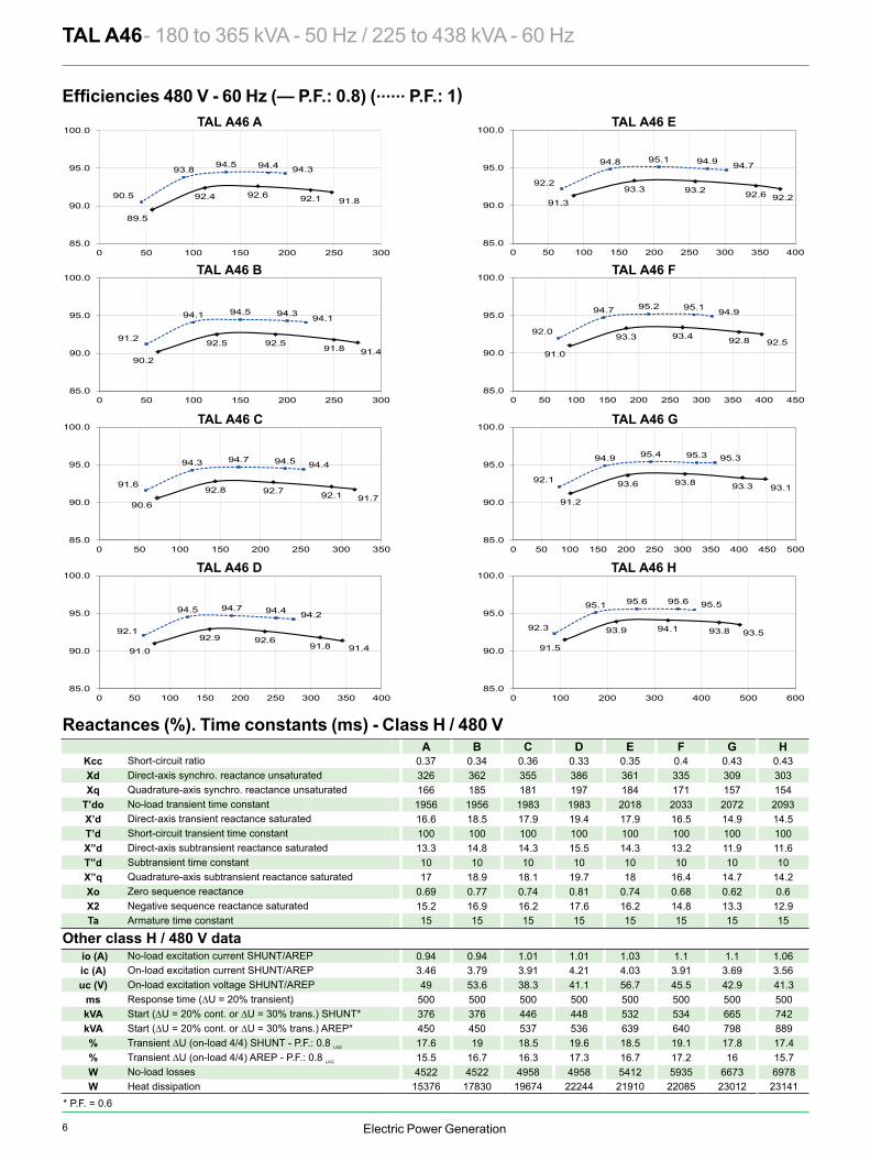
TAL A46 - 180 to 365 kVA - 50 Hz / 225 to 438 kVA - 60 Hz Transient voltage variation 400 V - 50 Hz
1) For a starting P.F. other than 0.6, the starting kVA must be multiplied by K = Sine P.F. / 0.82) For voltages other than 400V (Y), 230V (Δ) at 50 Hz, then kVA must be multiplied by (400/U)2 or (230/U)2.
Phase loading (SHUNT) - kVA at P.F. = 0.8 Phase loading (AREP) - kVA at P.F. = 0.8
Load shedding (SHUNT) - kVA at P.F. = 0.8 Load shedding (AREP) - kVA at P.F. = 0.8
Motor starting (SHUNT) Locked rotor kVA at P.F. = 0.6
Motor starting (AREP) Locked rotor kVA at P.F. = 0.6
Volta
ge d
rop
Volta
ge d
rop
Volta
ge ri
se
Volta
ge ri
se
Volta
ge d
rop
Volta
ge d
rop
C
M
Y
CM
MY
CY
CMY
K
TALA46 5675b_en.pdf 1 2019/1/9 17:59:27
6 Electric Power Generation
93.593.894.193.9
91.5
95.595.695.695.1
92.3
85.0
90.0
95.0
100.0
0 100 200 300 400 500 600
93.193.393.893.6
91.2
95.395.395.494.9
92.1
85.0
90.0
95.0
100.0
0 50 100 150 200 250 300 350 400 450 500
92.592.893.493.3
91.0
94.995.195.294.7
92.0
85.0
90.0
95.0
100.0
0 50 100 150 200 250 300 350 400 450
92.292.693.293.3
91.3
94.794.995.194.8
92.2
85.0
90.0
95.0
100.0
0 50 100 150 200 250 300 350 400
91.491.892.692.9
91.0
94.294.494.794.5
92.1
85.0
90.0
95.0
100.0
0 50 100 150 200 250 300 350 400
91.792.192.792.8
90.6
94.494.594.794.3
91.6
85.0
90.0
95.0
100.0
0 50 100 150 200 250 300 350
91.491.892.592.5
90.2
94.194.394.594.1
91.2
85.0
90.0
95.0
100.0
0 50 100 150 200 250 300
91.892.192.692.4
89.5
94.394.494.593.8
90.5
85.0
90.0
95.0
100.0
0 50 100 150 200 250 300
A B C D E F G HKcc 0.37 0.34 0.36 0.33 0.35 0.4 0.43 0.43Xd 326 362 355 386 361 335 309 303Xq 166 185 181 197 184 171 157 154
T’do 1956 1956 1983 1983 2018 2033 2072 2093X’d 16.6 18.5 17.9 19.4 17.9 16.5 14.9 14.5T’d 100 100 100 100 100 100 100 100X”d 13.3 14.8 14.3 15.5 14.3 13.2 11.9 11.6T”d 10 10 10 10 10 10 10 10X”q 17 18.9 18.1 19.7 18 16.4 14.7 14.2Xo 0.69 0.77 0.74 0.81 0.74 0.68 0.62 0.6X2 15.2 16.9 16.2 17.6 16.2 14.8 13.3 12.9Ta 15 15 15 15 15 15 15 15
io (A) 0.94 0.94 1.01 1.01 1.03 1.1 1.1 1.06ic (A) 3.46 3.79 3.91 4.21 4.03 3.91 3.69 3.56uc (V) 49 53.6 38.3 41.1 56.7 45.5 42.9 41.3
ms 500 500 500 500 500 500 500 500kVA 376 376 446 448 532 534 665 742kVA 450 450 537 536 639 640 798 889% 17.6 19 18.5 19.6 18.5 19.1 17.8 17.4% 15.5 16.7 16.3 17.3 16.7 17.2 16 15.7W 4522 4522 4958 4958 5412 5935 6673 6978W 15376 17830 19674 22244 21910 22085 23012 23141
TAL A46 E
TAL A46 F
TAL A46 C TAL A46 G
TAL A46 D TAL A46 H
TAL A46 A
TAL A46 B
TAL A46 - 180 to 365 kVA - 50 Hz / 225 to 438 kVA - 60 Hz
— P.F.: 0.8) (...... P.F.: 1)
Short-circuit ratioDirect-axis synchro. reactance unsaturatedQuadrature-axis synchro. reactance unsaturatedNo-load transient time constantDirect-axis transient reactance saturatedShort-circuit transient time constantDirect-axis subtransient reactance saturatedSubtransient time constantQuadrature-axis subtransient reactance saturatedZero sequence reactanceNegative sequence reactance saturatedArmature time constant
Other class H / 480 V dataNo-load excitation current SHUNT/AREPOn-load excitation current SHUNT/AREPOn-load excitation voltage SHUNT/AREPResponse time (∆U = 20% transient)Start (∆U = 20% cont. or ∆U = 30% trans.) SHUNT*Start (∆U = 20% cont. or ∆U = 30% trans.) AREP*Transient ∆U (on-load 4/4) SHUNT - P.F.: 0.8 LAG
Transient ∆U (on-load 4/4) AREP - P.F.: 0.8 LAG
No-load lossesHeat dissipation
Reactances (%). Time constants (ms) - Class H / 480 V
* P.F. = 0.6
C
M
Y
CM
MY
CY
CMY
K
TALA46 5675b_en.pdf 1 2019/1/9 17:59:41

7Electric Power Generation
93.593.894.193.9
91.5
95.595.695.695.1
92.3
85.0
90.0
95.0
100.0
0 100 200 300 400 500 600
93.193.393.893.6
91.2
95.395.395.494.9
92.1
85.0
90.0
95.0
100.0
0 50 100 150 200 250 300 350 400 450 500
92.592.893.493.3
91.0
94.995.195.294.7
92.0
85.0
90.0
95.0
100.0
0 50 100 150 200 250 300 350 400 450
92.292.693.293.3
91.3
94.794.995.194.8
92.2
85.0
90.0
95.0
100.0
0 50 100 150 200 250 300 350 400
91.491.892.692.9
91.0
94.294.494.794.5
92.1
85.0
90.0
95.0
100.0
0 50 100 150 200 250 300 350 400
91.792.192.792.8
90.6
94.494.594.794.3
91.6
85.0
90.0
95.0
100.0
0 50 100 150 200 250 300 350
91.491.892.592.5
90.2
94.194.394.594.1
91.2
85.0
90.0
95.0
100.0
0 50 100 150 200 250 300
91.892.192.692.4
89.5
94.394.494.593.8
90.5
85.0
90.0
95.0
100.0
0 50 100 150 200 250 300
A B C D E F G HKcc 0.37 0.34 0.36 0.33 0.35 0.4 0.43 0.43Xd 326 362 355 386 361 335 309 303Xq 166 185 181 197 184 171 157 154
T’do 1956 1956 1983 1983 2018 2033 2072 2093X’d 16.6 18.5 17.9 19.4 17.9 16.5 14.9 14.5T’d 100 100 100 100 100 100 100 100X”d 13.3 14.8 14.3 15.5 14.3 13.2 11.9 11.6T”d 10 10 10 10 10 10 10 10X”q 17 18.9 18.1 19.7 18 16.4 14.7 14.2Xo 0.69 0.77 0.74 0.81 0.74 0.68 0.62 0.6X2 15.2 16.9 16.2 17.6 16.2 14.8 13.3 12.9Ta 15 15 15 15 15 15 15 15
io (A) 0.94 0.94 1.01 1.01 1.03 1.1 1.1 1.06ic (A) 3.46 3.79 3.91 4.21 4.03 3.91 3.69 3.56uc (V) 49 53.6 38.3 41.1 56.7 45.5 42.9 41.3
ms 500 500 500 500 500 500 500 500kVA 376 376 446 448 532 534 665 742kVA 450 450 537 536 639 640 798 889% 17.6 19 18.5 19.6 18.5 19.1 17.8 17.4% 15.5 16.7 16.3 17.3 16.7 17.2 16 15.7W 4522 4522 4958 4958 5412 5935 6673 6978W 15376 17830 19674 22244 21910 22085 23012 23141
TAL A46 E
TAL A46 F
TAL A46 C TAL A46 G
TAL A46 D TAL A46 H
TAL A46 A
TAL A46 B
TAL A46 - 180 to 365 kVA - 50 Hz / 225 to 438 kVA - 60 Hz
— P.F.: 0.8) (...... P.F.: 1)
Short-circuit ratioDirect-axis synchro. reactance unsaturatedQuadrature-axis synchro. reactance unsaturatedNo-load transient time constantDirect-axis transient reactance saturatedShort-circuit transient time constantDirect-axis subtransient reactance saturatedSubtransient time constantQuadrature-axis subtransient reactance saturatedZero sequence reactanceNegative sequence reactance saturatedArmature time constant
Other class H / 480 V dataNo-load excitation current SHUNT/AREPOn-load excitation current SHUNT/AREPOn-load excitation voltage SHUNT/AREPResponse time (∆U = 20% transient)Start (∆U = 20% cont. or ∆U = 30% trans.) SHUNT*Start (∆U = 20% cont. or ∆U = 30% trans.) AREP*Transient ∆U (on-load 4/4) SHUNT - P.F.: 0.8 LAG
Transient ∆U (on-load 4/4) AREP - P.F.: 0.8 LAG
No-load lossesHeat dissipation
Reactances (%). Time constants (ms) - Class H / 480 V
* P.F. = 0.6
C
M
Y
CM
MY
CY
CMY
K
TALA46 5675b_en.pdf 1 2019/1/9 17:59:41
Electric Power Generation
0%
5%
10%
15%
20%
25%
30%
0 100 200 300 400 500 600 700 800 900 1000 1100
0%
5%
10%
15%
20%
25%
30%
0 100 200 300 400 500 600 700 800 900 1000 1100
0%
5%
10%
15%
20%
25%
30%
0 100 200 300 400 500 600 700 800 900 1000 1100
0%
5%
10%
15%
20%
25%
30%
0 100 200 300 400 500 600 700 800 900 1000 1100
0%
5%
10%
15%
20%
25%
30%
0 100 200 300 400 500 600 700 800 900 1000 1100
0%
5%
10%
15%
20%
25%
30%
0 100 200 300 400 500 600 700 800 900 1000 1100
A B C E G HD F
A B C E G HD F
AB C E G HD F AB C E G HD F
A B C E G HD F
A B C E G HD F
TAL A46 - 180 to 365 kVA - 50 Hz / 225 to 438 kVA - 60 Hz Transient voltage variation 480 V - 60 Hz
1) For a starting P.F. other than 0.6, the starting kVA must be multiplied by K = Sine P.F. / 0.82) For voltages other than 480V (Y), 277V (Δ), 240V (YY) at 60 Hz, then kVA must be multiplied by (480/U)2 or (277/U)2 or (240/U)2.
Phase loading (SHUNT) - kVA at P.F. = 0.8 Phase loading (AREP) - kVA at P.F. = 0.8
Load shedding (SHUNT) - kVA at P.F. = 0.8 Load shedding (AREP) - kVA at P.F. = 0.8
Motor starting (SHUNT) Locked rotor kVA at P.F. = 0.6
Motor starting (AREP) Locked rotor kVA at P.F. = 0.6
Volta
ge d
rop
Volta
ge d
rop
Volta
ge ri
se
Volta
ge ri
se
Volta
ge d
rop
Volta
ge d
rop
C
M
Y
CM
MY
CY
CMY
K
TALA46 5675b_en.pdf 1 2019/1/9 17:59:55
8 Electric Power Generation
In In
1
10
100
1000
10000
1 10 100 1000
In In
1
10
100
1000
10000
1 10 100 1000
In In
1
10
100
1000
10000
1 10 100 1000
In In
1
10
100
1000
10000
1 10 100 1000
AREP
SHUNT
AREP
SHUNT
AREP
SHUNT
AREP
SHUNT
TAL A46 - 180 to 365 kVA - 50 Hz / 225 to 438 kVA - 60 Hz
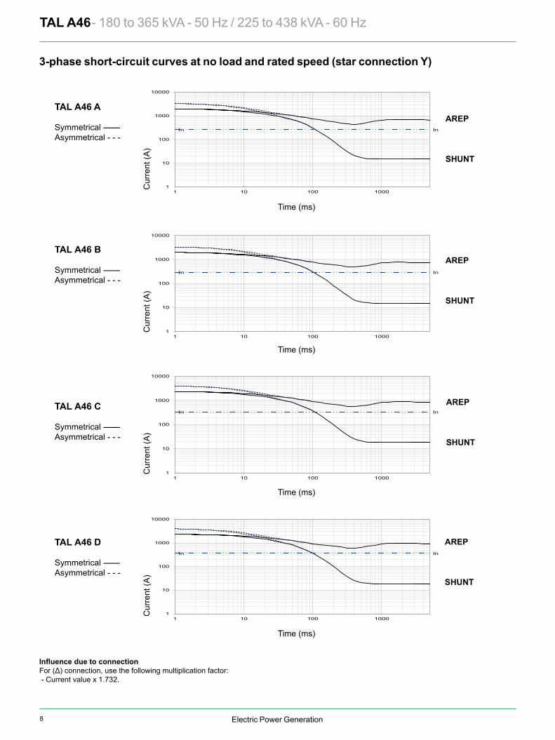
For (Δ) connection, use the following multiplication factor: - Current value x 1.732.
TAL A46 A
Symmetrical --------Asymmetrical - - -
TAL A46 B
Symmetrical --------Asymmetrical - - -
TAL A46 C
Symmetrical --------Asymmetrical - - -
Time (ms)
Time (ms)
Time (ms)
Time (ms)
Cur
rent
(A)
Cur
rent
(A)
Cur
rent
(A)
Cur
rent
(A)
TAL A46 D
Symmetrical --------Asymmetrical - - -
3-phase short-circuit curves at no load and rated speed (star connection Y)
C
M
Y
CM
MY
CY
CMY
K
TALA46 5675b_en.pdf 1 2019/1/9 18:00:06

9Electric Power Generation
In In
1
10
100
1000
10000
1 10 100 1000
In In
1
10
100
1000
10000
1 10 100 1000
In In
1
10
100
1000
10000
1 10 100 1000
In In
1
10
100
1000
10000
1 10 100 1000
AREP
SHUNT
AREP
SHUNT
AREP
SHUNT
AREP
SHUNT
TAL A46 - 180 to 365 kVA - 50 Hz / 225 to 438 kVA - 60 Hz
For (Δ) connection, use the following multiplication factor: - Current value x 1.732.
TAL A46 A
Symmetrical --------Asymmetrical - - -
TAL A46 B
Symmetrical --------Asymmetrical - - -
TAL A46 C
Symmetrical --------Asymmetrical - - -
Time (ms)
Time (ms)
Time (ms)
Time (ms)
Cur
rent
(A)
Cur
rent
(A)
Cur
rent
(A)
Cur
rent
(A)
TAL A46 D
Symmetrical --------Asymmetrical - - -
3-phase short-circuit curves at no load and rated speed (star connection Y)
C
M
Y
CM
MY
CY
CMY
K
TALA46 5675b_en.pdf 1 2019/1/9 18:00:06
Electric Power Generation
In In
1
10
100
1000
10000
1 10 100 1000
In In
1
10
100
1000
10000
1 10 100 1000
In In
1
10
100
1000
10000
1 10 100 1000
In In
1
10
100
1000
10000
1 10 100 1000
AREP
SHUNT
AREP
SHUNT
AREP
SHUNT
AREP
SHUNT
TAL A46 - 180 to 365 kVA - 50 Hz / 225 to 438 kVA - 60 Hz
TAL A46 E
Symmetrical --------Asymmetrical - - -
TAL A46 F
Symmetrical --------Asymmetrical - - -
TAL A46 G
Symmetrical --------Asymmetrical - - -
Time (ms)
Time (ms)
Time (ms)
Time (ms)
Cur
rent
(A)
Cur
rent
(A)
Cur
rent
(A)
Cur
rent
(A)
TAL A46 H
Symmetrical --------Asymmetrical - - -
Curves are based on a three-phase short-circuit.For other types of short-circuit, use the following multiplication factors.
3 - phase 2 - phase L / L 1 - phase L / NInstantaneous (max.) 1 0.87 1.3Continuous 1 1.5 2.2Maximum duration 1.5
3-phase short-circuit curves at no load and rated speed (star connection Y)
C
M
Y
CM
MY
CY
CMY
K
TALA46 5675b_en.pdf 1 2019/1/9 18:00:16

10 Electric Power Generation
LB Xg C 11 1/2 14 18TAL A46 A 944**/935 892 408 429 569 XTAL A46 B 944**/935 892 414 429 599 XTAL A46 C 944**/935 892 423 429 674 X XTAL A46 D 944**/935 892 423 429 682 XTAL A46 E 989**/980 937 445 429 754 X XTAL A46 F 989**/980 937 445 429 754TAL A46 G* 1084**/1075 1032 493 525 888TAL A46 H* 1084**/1075 1032 493 525 888
S.A.E. P N M S ß ° S.A.E. BX U X Y AH3 641 409.575 428.625 11 15° 11 1/2 352.42 333.38 8 11 39.62 641 447.675 466.725 11 15° 14 466.72 438.15 8 14 25.41 641 511.175 530.225 12 15° 18*** 571.5 542.92 6 17 15.7
1/2 713 584.2 619.125 14 15°0 713 647.7 679.45 14 11° 15’
Xr Lr M J Xr Lr M J TAL A46 A 413 923 243 2.46 401 923 244 2.62TAL A46 B 413 923 243 2.46 401 923 244 2.62TAL A46 C 420 923 255 2.64 408 923 256 2.8TAL A46 D 420 923 255 2.64 408 923 256 2.8TAL A46 E 460 968 304 3.28 448 968 305 3.44TAL A46 F 460 968 304 3.28 448 968 305 3.44TAL A46 G 508 1063 358 3.97 497 1063 359 4.13TAL A46 H 508 1063 358 3.97 497 1063 359 4.13
Ø 7
5
Ø 1
00
Ø 1
10
Ø 1
14.8
Ø 1
15
Ø 1
20
Ø 1
15
Ø 1
10Ø
88
Ø 7
5
Lr
Xr
*** Option
TAL A46 - 180 to 365 kVA - 50 Hz / 225 to 438 kVA - 60 Hz Single bearing general arrangement
Flange S.A.E 2Flange S.A.E 3
CouplingFlex plate
Flange S.A.E 1/2Flange S.A.E 0
Flange S.A.E 1
Dimensions (mm) and weightType
Flange (mm) Flex plate (mm)
Weight (kg)L without PMG
Centre of gravity: Xr (mm), Rotor length: Lr (mm), Weight: M (kg), Moment of inertia: J (kgm2): (4J = MD2)Flex plate S.A.E. 11 ½ Flex plate S.A.E. 14
Type
Torsional data
* Shaft height = 355 mm optional ** Dimensions with SAE 11 1/2
NOTE : upon request.
PMG optional
AIR OUTLET
S DIA. Qty 12 as shown on Ø M
Access to rotating diodes
AIR INLET
Access to regulator
Access to terminals
Y DIA, Qty X Eq. Sp. on Ø U.
Standard cableoutput
Optional cableoutput
Option
L LB
Xg
Ø B
XØ P
Ø N
AH568
457 737 610 21
367
421
485.
5 (1
2-w
ire)
280
355
(o
ptio
n)
12
0 - 0,1
27
- 0,0
50- 0
,100
6198
6
506
C
40
170868
80 80
Ø 206
0 - 2
0 - 2
ß94.3
Ø 2
35
C
M
Y
CM
MY
CY
CMY
K
TALA46 5675b_en.pdf 1 2019/1/9 18:00:30
11Electric Power Generation
LB Xg C 11 1/2 14 18TAL A46 A 944**/935 892 408 429 569 XTAL A46 B 944**/935 892 414 429 599 XTAL A46 C 944**/935 892 423 429 674 X XTAL A46 D 944**/935 892 423 429 682 XTAL A46 E 989**/980 937 445 429 754 X XTAL A46 F 989**/980 937 445 429 754TAL A46 G* 1084**/1075 1032 493 525 888TAL A46 H* 1084**/1075 1032 493 525 888
S.A.E. P N M S ß ° S.A.E. BX U X Y AH3 641 409.575 428.625 11 15° 11 1/2 352.42 333.38 8 11 39.62 641 447.675 466.725 11 15° 14 466.72 438.15 8 14 25.41 641 511.175 530.225 12 15° 18*** 571.5 542.92 6 17 15.7
1/2 713 584.2 619.125 14 15°0 713 647.7 679.45 14 11° 15’
Xr Lr M J Xr Lr M J TAL A46 A 413 923 243 2.46 401 923 244 2.62TAL A46 B 413 923 243 2.46 401 923 244 2.62TAL A46 C 420 923 255 2.64 408 923 256 2.8TAL A46 D 420 923 255 2.64 408 923 256 2.8TAL A46 E 460 968 304 3.28 448 968 305 3.44TAL A46 F 460 968 304 3.28 448 968 305 3.44TAL A46 G 508 1063 358 3.97 497 1063 359 4.13TAL A46 H 508 1063 358 3.97 497 1063 359 4.13
Ø 7
5
Ø 1
00
Ø 1
10
Ø 1
14.8
Ø 1
15
Ø 1
20
Ø 1
15
Ø 1
10Ø
88
Ø 7
5
Lr
Xr
*** Option
TAL A46 - 180 to 365 kVA - 50 Hz / 225 to 438 kVA - 60 Hz Single bearing general arrangement
Flange S.A.E 2Flange S.A.E 3
CouplingFlex plate
Flange S.A.E 1/2Flange S.A.E 0
Flange S.A.E 1
Dimensions (mm) and weightType
Flange (mm) Flex plate (mm)
Weight (kg)L without PMG
Centre of gravity: Xr (mm), Rotor length: Lr (mm), Weight: M (kg), Moment of inertia: J (kgm2): (4J = MD2)Flex plate S.A.E. 11 ½ Flex plate S.A.E. 14
Type
Torsional data
* Shaft height = 355 mm optional ** Dimensions with SAE 11 1/2
NOTE : upon request.
PMG optional
AIR OUTLET
S DIA. Qty 12 as shown on Ø M
Access to rotating diodes
AIR INLET
Access to regulator
Access to terminals
Y DIA, Qty X Eq. Sp. on Ø U.
Standard cableoutput
Optional cableoutput
Option
L LB
Xg
Ø B
XØ P
Ø N
AH568
457 737 610 21
367
421
485.
5 (1
2-w
ire)
280
355
(o
ptio
n)
12
0 - 0,1
27
- 0,0
50- 0
,100
6198
6
506
C
40
170868
80 80
Ø 206
0 - 2
0 - 2
ß94.3
Ø 2
35
C
M
Y
CM
MY
CY
CMY
K
TALA46 5675b_en.pdf 1 2019/1/9 18:00:30
Electric Power Generation
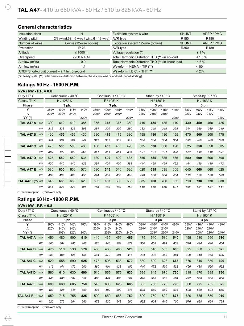
Phase 3 ph. 3 ph. 3 ph. 3 ph.Y 380V 416V 440V 480V 380V 416V 440V 480V 380V 416V 440V 480V 380V 416V 440V 480V∆ 220V 240V 240V 220V 240V 240V 220V 240V 240V 220V 240V 240V
YY (*) 208V 220V 240V 208V 220V 240V 208V 220V 240V 208V 220V 240V
TAL A47 A kVA 450 480 500 510 410 435 455 465 475 510 530 540 495 530 550 580kW 360 384 400 408 328 348 364 372 380 408 424 432 396 424 440 464
TAL A47 B kVA 475 510 530 570 430 465 480 520 505 540 560 605 525 560 585 625kW 380 408 424 456 344 372 384 416 404 432 448 484 420 448 468 500
TAL A47 C kVA 520 555 590 625 475 505 535 570 550 590 625 665 570 610 650 690kW 416 444 472 500 380 404 428 456 440 472 500 532 456 488 520 552
TAL A47 D kVA 560 610 630 690 510 555 575 630 595 645 670 730 615 670 695 750kW 448 488 504 552 408 444 460 504 476 516 536 584 492 536 556 600
TAL A47 E kVA 600 660 685 750 545 600 625 685 635 700 725 795 660 725 755 825kW 480 528 548 600 436 480 500 548 508 560 580 636 528 580 604 660
TAL A47 F (**) kVA 650 715 755 825 590 650 685 750 690 760 800 875 720 785 830 910kW 520 572 604 660 472 520 548 600 552 608 640 700 576 628 664 728
Phase 3 ph. 3 ph. 3 ph. 3 ph.Y 380V 400V 415V 440V 380V 400V 415V 440V 380V 400V 415V 440V 380V 400V 415V 440V∆ 220V 230V 240V 220V 230V 240V 220V 230V 240V 220V 230V 240V
YY (*) 220V 220V 220V 220V
TAL A47 A kVA 390 410 410 385 355 375 375 350 415 435 435 410 430 450 450 425kW 312 328 328 308 284 300 300 280 332 348 348 328 344 360 360 340
TAL A47 B kVA 430 455 455 430 390 415 415 390 455 480 480 455 475 500 500 475kW 344 364 364 344 312 332 332 312 364 384 384 364 380 400 400 380
TAL A47 C kVA 475 500 500 460 430 455 455 420 505 530 530 490 525 550 550 505kW 380 400 400 368 344 364 364 336 404 424 424 392 420 440 440 404
TAL A47 D kVA 525 550 550 535 480 500 500 485 555 585 585 565 580 600 600 590kW 420 440 440 428 384 400 400 388 444 468 468 452 464 480 480 472
TAL A47 E kVA 585 600 600 570 530 545 545 520 620 635 635 605 645 660 660 625kW 468 480 480 456 424 436 436 416 496 508 508 484 516 528 528 500
TAL A47 F (**) kVA 645 660 660 620 585 600 600 565 685 700 700 655 710 730 730 680kW 516 528 528 496 468 480 480 452 548 560 560 524 568 584 584 544
TAL A47 - 410 to 660 kVA - 50 Hz / 510 to 825 kVA - 60 Hz General characteristics
Ratings 50 Hz - 1500 R.P.M.
Insulation class H Excitation system 6-wire SHUNT AREP / PMGWinding pitch 2/3 (wind.6S - 6-wire / wind.6 - 12-wire) AVR type R150 R180Number of wires 6-wire (12-wire option) Excitation system 12-wire (option) SHUNT AREP / PMGProtection IP 23 AVR type R250 R180Altitude ≤ 1000 m Voltage regulation (*) ± 1 %Overspeed 2250 R.P.M. Total Harmonic Distortion THD (**) in no-load < 1.5 %
3/s) 0.9 Total Harmonic Distortion THD (**) in linear load < 5 %3/s) 1.1 Waveform: NEMA = TIF (**) < 50
AREP Short-circuit current = 2.7 In : 5 second Waveform: I.E.C. = THF (**) < 2%(*) Steady state (**) Total harmonic distortion between phases, no-load or on-load (non-distorting)
kVA / kW - P.F. = 0.8Duty / T° C Continuous / 40 °C Continuous / 40 °C Stand-by / 40 °C Stand-by / 27 °CClass / T° K H / 125° K F / 105° K H / 150° K H / 163° K
kVA / kW - P.F. = 0.8Duty / T° C Continuous / 40 °C Continuous / 40 °C Stand-by / 40 °C Stand-by / 27 °CClass / T° K H / 125° K F / 105° K H / 150° K H / 163° K
Ratings 60 Hz - 1800 R.P.M.
(*) 12-wire option (**) 6-wire only
(*) 12-wire option (**) 6-wire only
C
M
Y
CM
MY
CY
CMY
K
TALA47 5676b_en.pdf 1 2019/1/9 18:00:44
12 Electric Power Generation
94.794.995.595.8
94.8
96.596.796.996.8
95.5
90.0
92.5
95.0
97.5
100.0
0 200 400 600 800
94.394.695.395.7
94.8
96.396.496.896.8
95.6
90.0
92.5
95.0
97.5
100.0
0 100 200 300 400 500 600 700
94.494.795.395.5
94.3
96.496.596.796.5
95.0
90.0
92.5
95.0
97.5
100.0
0 100 200 300 400 500 600 700
93.593.994.7
95.294.3
95.896.096.496.4
95.2
90.0
92.5
95.0
97.5
100.0
0 100 200 300 400 500 600
93.994.294.995.2
94.1
96.096.196.496.3
94.8
90.0
92.5
95.0
97.5
100.0
0 100 200 300 400 500 600
92.993.394.1
94.693.5
95.595.796.096.0
94.4
90.0
92.5
95.0
97.5
100.0
0 100 200 300 400 500
A B C D E FKcc 0.35 0.34 0.31 0.39 0.32 0.36Xd 347 338 372 310 361 328Xq 177 172 189 158 184 167
T’do 1601 1705 1705 1773 1797 1832X’d 21.6 19.8 21.8 17.5 20 17.9T’d 100 100 100 100 100 100X”d 15.1 13.9 15.2 12.2 14 12.5T”d 10 10 10 10 10 10X”q 16.6 17.4 19.1 16.5 19.5 18Xo 0.9 0.82 0.9 0.72 0.83 0.74X2 15.91 15.66 17.21 14.41 16.8 15.31Ta 15 15 15 15 15 15
io (A) 0.97 0.87 0.87 0.97 0.85 0.93ic (A) 4.24 3.72 4.06 3.79 3.89 3.87uc (V) 44.2 38.7 42.2 39.4 40.3 40.1
ms 500 500 500 500 500 500kVA 612 743 742 947 970 1105kVA 738 891 894 1135 1162 1324 % 18.6 17.5 18.7 18.7 17.6 18.9 % 16.3 15.3 16.4 16.8 15.4 17W 4261 4376 4376 5192 4831 5487W 23451 22295 25923 24391 27055 27875
TAL A47A
TAL A47B TAL A47E
TAL A47C
TAL A47D
TAL A47F
TAL A47 - 410 to 660 kVA - 50 Hz / 510 to 825 kVA - 60 Hz
— P.F.: 0.8) (...... P.F.: 1)
Short-circuit ratioDirect-axis synchro. reactance unsaturatedQuadrature-axis synchro. reactance unsaturatedNo-load transient time constantDirect-axis transient reactance saturatedShort-circuit transient time constantDirect-axis subtransient reactance saturatedSubtransient time constantQuadrature-axis subtransient reactance saturatedZero sequence reactance Negative sequence reactance saturatedArmature time constant
Other class H / 400 V dataNo-load excitation current SHUNT/AREPOn-load excitation current SHUNT/AREPOn-load excitation voltage SHUNT/AREPResponse time (∆U = 20% transient)Start (∆U = 20% cont. or ∆U = 30% trans.) SHUNT*Start (∆U = 20% cont. or ∆U = 30% trans.) AREP*Transient ∆U (on-load 4/4) SHUNT - P.F.: 0.8 LAG
Transient ∆U (on-load 4/4) AREP - P.F.: 0.8 LAG
No-load lossesHeat dissipation
Reactances (%). Time constants (ms) - Class H / 400 V
* P.F. = 0.6
C
M
Y
CM
MY
CY
CMY
K
TALA47 5676b_en.pdf 1 2019/1/9 18:00:58
13Electric Power Generation
94.794.995.595.8
94.8
96.596.796.996.8
95.5
90.0
92.5
95.0
97.5
100.0
0 200 400 600 800
94.394.695.395.7
94.8
96.396.496.896.8
95.6
90.0
92.5
95.0
97.5
100.0
0 100 200 300 400 500 600 700
94.494.795.395.5
94.3
96.496.596.796.5
95.0
90.0
92.5
95.0
97.5
100.0
0 100 200 300 400 500 600 700
93.593.994.7
95.294.3
95.896.096.496.4
95.2
90.0
92.5
95.0
97.5
100.0
0 100 200 300 400 500 600
93.994.294.995.2
94.1
96.096.196.496.3
94.8
90.0
92.5
95.0
97.5
100.0
0 100 200 300 400 500 600
92.993.394.1
94.693.5
95.595.796.096.0
94.4
90.0
92.5
95.0
97.5
100.0
0 100 200 300 400 500
A B C D E FKcc 0.35 0.34 0.31 0.39 0.32 0.36Xd 347 338 372 310 361 328Xq 177 172 189 158 184 167
T’do 1601 1705 1705 1773 1797 1832X’d 21.6 19.8 21.8 17.5 20 17.9T’d 100 100 100 100 100 100X”d 15.1 13.9 15.2 12.2 14 12.5T”d 10 10 10 10 10 10X”q 16.6 17.4 19.1 16.5 19.5 18Xo 0.9 0.82 0.9 0.72 0.83 0.74X2 15.91 15.66 17.21 14.41 16.8 15.31Ta 15 15 15 15 15 15
io (A) 0.97 0.87 0.87 0.97 0.85 0.93ic (A) 4.24 3.72 4.06 3.79 3.89 3.87uc (V) 44.2 38.7 42.2 39.4 40.3 40.1
ms 500 500 500 500 500 500kVA 612 743 742 947 970 1105kVA 738 891 894 1135 1162 1324 % 18.6 17.5 18.7 18.7 17.6 18.9 % 16.3 15.3 16.4 16.8 15.4 17W 4261 4376 4376 5192 4831 5487W 23451 22295 25923 24391 27055 27875
TAL A47A
TAL A47B TAL A47E
TAL A47C
TAL A47D
TAL A47F
TAL A47 - 410 to 660 kVA - 50 Hz / 510 to 825 kVA - 60 Hz
— P.F.: 0.8) (...... P.F.: 1)
Short-circuit ratioDirect-axis synchro. reactance unsaturatedQuadrature-axis synchro. reactance unsaturatedNo-load transient time constantDirect-axis transient reactance saturatedShort-circuit transient time constantDirect-axis subtransient reactance saturatedSubtransient time constantQuadrature-axis subtransient reactance saturatedZero sequence reactance Negative sequence reactance saturatedArmature time constant
Other class H / 400 V dataNo-load excitation current SHUNT/AREPOn-load excitation current SHUNT/AREPOn-load excitation voltage SHUNT/AREPResponse time (∆U = 20% transient)Start (∆U = 20% cont. or ∆U = 30% trans.) SHUNT*Start (∆U = 20% cont. or ∆U = 30% trans.) AREP*Transient ∆U (on-load 4/4) SHUNT - P.F.: 0.8 LAG
Transient ∆U (on-load 4/4) AREP - P.F.: 0.8 LAG
No-load lossesHeat dissipation
Reactances (%). Time constants (ms) - Class H / 400 V
* P.F. = 0.6
C
M
Y
CM
MY
CY
CMY
K
TALA47 5676b_en.pdf 1 2019/1/9 18:00:58
Electric Power Generation
0%
5%
10%
15%
20%
25%
30%
0 200 400 600 800 1000 1200 1400
0%
5%
10%
15%
20%
25%
30%
0 200 400 600 800 1000 1200 1400
0%
5%
10%
15%
20%
25%
30%
0 200 400 600 800 1000 1200 1400
0%
5%
10%
15%
20%
25%
30%
0 200 400 600 800 1000 1200 1400
0%
5%
10%
15%
20%
25%
30%
0 200 400 600 800 1000 1200 1400
0%
5%
10%
15%
20%
25%
30%
0 200 400 600 800 1000 1200 1400
A B C ED F
A B C ED F
A B C ED F A B C ED F
A B C ED F
A B C ED F
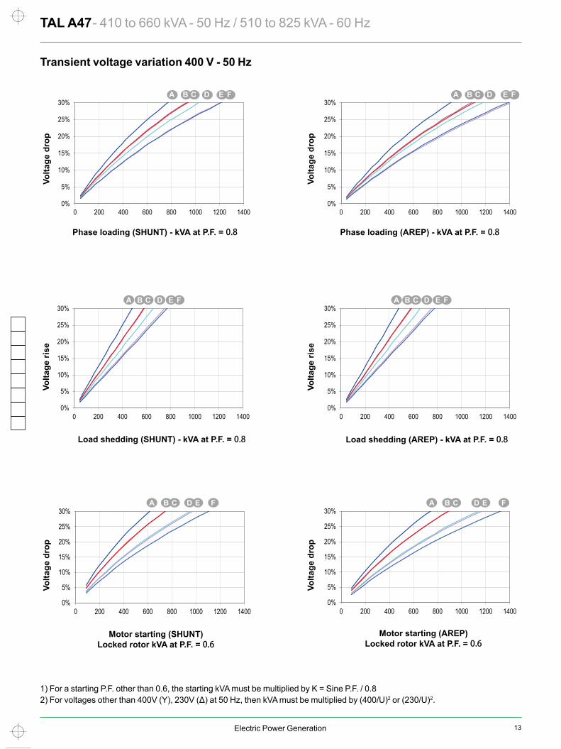
TAL A47 - 410 to 660 kVA - 50 Hz / 510 to 825 kVA - 60 Hz Transient voltage variation 400 V - 50 Hz
1) For a starting P.F. other than 0.6, the starting kVA must be multiplied by K = Sine P.F. / 0.82) For voltages other than 400V (Y), 230V (Δ) at 50 Hz, then kVA must be multiplied by (400/U)2 or (230/U)2.
Phase loading (SHUNT) - kVA at P.F. = 0.8 Phase loading (AREP) - kVA at P.F. = 0.8
Load shedding (SHUNT) - kVA at P.F. = 0.8 Load shedding (AREP) - kVA at P.F. = 0.8
Motor starting (SHUNT) Locked rotor kVA at P.F. = 0.6
Motor starting (AREP) Locked rotor kVA at P.F. = 0.6
Volta
ge d
rop
Volta
ge d
rop
Volta
ge ri
se
Volta
ge ri
se
Volta
ge d
rop
Volta
ge d
rop
C
M
Y
CM
MY
CY
CMY
K
TALA47 5676b_en.pdf 1 2019/1/9 18:01:25
14 Electric Power Generation
94.194.494.994.9
93.3
96.096.196.396.0
94.0
90.0
92.5
95.0
97.5
100.0
0 100 200 300 400 500 600 700
93.894.194.795.0
93.7
95.896.096.296.1
94.4
90.0
92.5
95.0
97.5
100.0
0 200 400 600 800
93.293.694.294.3
92.6
95.595.795.995.6
93.4
90.0
92.5
95.0
97.5
100.0
0 100 200 300 400 500 600
94.694.895.395.3
93.6
96.496.596.596.2
94.2
90.0
92.5
95.0
97.5
100.0
0 200 400 600 800
94.594.895.395.5
94.2
96.396.496.696.5
94.8
90.0
92.5
95.0
97.5
100.0
0 200 400 600 800 1000
94.995.195.595.6
94.2
96.596.696.896.5
94.8
90.0
92.5
95.0
97.5
100.0
0 200 400 600 800 1000
TAL A47A
TAL A47B TAL A47E
TAL A47C
TAL A47D
TAL A47F
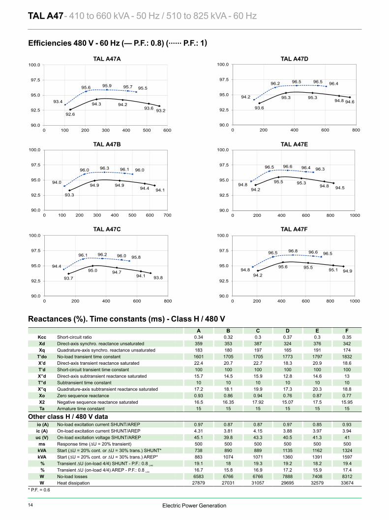
A B C D E FKcc 0.34 0.32 0.3 0.37 0.3 0.35Xd 359 353 387 324 376 342Xq 183 180 197 165 191 174
T’do 1601 1705 1705 1773 1797 1832X’d 22.4 20.7 22.7 18.3 20.9 18.6T’d 100 100 100 100 100 100X”d 15.7 14.5 15.9 12.8 14.6 13T”d 10 10 10 10 10 10X”q 17.2 18.1 19.9 17.3 20.3 18.8Xo 0.93 0.86 0.94 0.76 0.87 0.77X2 16.5 16.35 17.92 15.07 17.5 15.95Ta 15 15 15 15 15 15
io (A) 0.97 0.87 0.87 0.97 0.85 0.93ic (A) 4.31 3.81 4.15 3.88 3.97 3.94uc (V) 45.1 39.8 43.3 40.5 41.3 41
ms 500 500 500 500 500 500kVA 738 890 889 1135 1162 1324kVA 883 1074 1071 1360 1391 1597 % 19.1 18 19.3 19.2 18.2 19.4 % 16.7 15.8 16.9 17.2 15.9 17.4W 6583 6766 6766 7888 7408 8312W 27879 27031 31057 29695 32579 33674
TAL A47 - 410 to 660 kVA - 50 Hz / 510 to 825 kVA - 60 Hz
— P.F.: 0.8) (...... P.F.: 1)
Short-circuit ratioDirect-axis synchro. reactance unsaturatedQuadrature-axis synchro. reactance unsaturatedNo-load transient time constantDirect-axis transient reactance saturatedShort-circuit transient time constantDirect-axis subtransient reactance saturatedSubtransient time constantQuadrature-axis subtransient reactance saturatedZero sequence reactanceNegative sequence reactance saturatedArmature time constant
Other class H / 480 V dataNo-load excitation current SHUNT/AREPOn-load excitation current SHUNT/AREPOn-load excitation voltage SHUNT/AREPResponse time (∆U = 20% transient)Start (∆U = 20% cont. or ∆U = 30% trans.) SHUNT*Start (∆U = 20% cont. or ∆U = 30% trans.) AREP*Transient ∆U (on-load 4/4) SHUNT - P.F.: 0.8 LAG
Transient ∆U (on-load 4/4) AREP - P.F.: 0.8 LAG
No-load lossesHeat dissipation
Reactances (%). Time constants (ms) - Class H / 480 V
* P.F. = 0.6
C
M
Y
CM
MY
CY
CMY
K
TALA47 5676b_en.pdf 1 2019/1/9 18:01:11

15Electric Power Generation
94.194.494.994.9
93.3
96.096.196.396.0
94.0
90.0
92.5
95.0
97.5
100.0
0 100 200 300 400 500 600 700
93.894.194.795.0
93.7
95.896.096.296.1
94.4
90.0
92.5
95.0
97.5
100.0
0 200 400 600 800
93.293.694.294.3
92.6
95.595.795.995.6
93.4
90.0
92.5
95.0
97.5
100.0
0 100 200 300 400 500 600
94.694.895.395.3
93.6
96.496.596.596.2
94.2
90.0
92.5
95.0
97.5
100.0
0 200 400 600 800
94.594.895.395.5
94.2
96.396.496.696.5
94.8
90.0
92.5
95.0
97.5
100.0
0 200 400 600 800 1000
94.995.195.595.6
94.2
96.596.696.896.5
94.8
90.0
92.5
95.0
97.5
100.0
0 200 400 600 800 1000
TAL A47A
TAL A47B TAL A47E
TAL A47C
TAL A47D
TAL A47F
A B C D E FKcc 0.34 0.32 0.3 0.37 0.3 0.35Xd 359 353 387 324 376 342Xq 183 180 197 165 191 174
T’do 1601 1705 1705 1773 1797 1832X’d 22.4 20.7 22.7 18.3 20.9 18.6T’d 100 100 100 100 100 100X”d 15.7 14.5 15.9 12.8 14.6 13T”d 10 10 10 10 10 10X”q 17.2 18.1 19.9 17.3 20.3 18.8Xo 0.93 0.86 0.94 0.76 0.87 0.77X2 16.5 16.35 17.92 15.07 17.5 15.95Ta 15 15 15 15 15 15
io (A) 0.97 0.87 0.87 0.97 0.85 0.93ic (A) 4.31 3.81 4.15 3.88 3.97 3.94uc (V) 45.1 39.8 43.3 40.5 41.3 41
ms 500 500 500 500 500 500kVA 738 890 889 1135 1162 1324kVA 883 1074 1071 1360 1391 1597 % 19.1 18 19.3 19.2 18.2 19.4 % 16.7 15.8 16.9 17.2 15.9 17.4W 6583 6766 6766 7888 7408 8312W 27879 27031 31057 29695 32579 33674
TAL A47 - 410 to 660 kVA - 50 Hz / 510 to 825 kVA - 60 Hz
— P.F.: 0.8) (...... P.F.: 1)
Short-circuit ratioDirect-axis synchro. reactance unsaturatedQuadrature-axis synchro. reactance unsaturatedNo-load transient time constantDirect-axis transient reactance saturatedShort-circuit transient time constantDirect-axis subtransient reactance saturatedSubtransient time constantQuadrature-axis subtransient reactance saturatedZero sequence reactanceNegative sequence reactance saturatedArmature time constant
Other class H / 480 V dataNo-load excitation current SHUNT/AREPOn-load excitation current SHUNT/AREPOn-load excitation voltage SHUNT/AREPResponse time (∆U = 20% transient)Start (∆U = 20% cont. or ∆U = 30% trans.) SHUNT*Start (∆U = 20% cont. or ∆U = 30% trans.) AREP*Transient ∆U (on-load 4/4) SHUNT - P.F.: 0.8 LAG
Transient ∆U (on-load 4/4) AREP - P.F.: 0.8 LAG
No-load lossesHeat dissipation
Reactances (%). Time constants (ms) - Class H / 480 V
* P.F. = 0.6
C
M
Y
CM
MY
CY
CMY
K
TALA47 5676b_en.pdf 1 2019/1/9 18:01:11
Electric Power Generation
0%
5%
10%
15%
20%
25%
30%
0 200 400 600 800 1000 1200 1400 1600 1800
0%
5%
10%
15%
20%
25%
30%
0 200 400 600 800 1000 1200 1400 1600 1800
0%
5%
10%
15%
20%
25%
30%
0 200 400 600 800 1000 1200 1400 1600 1800
0%
5%
10%
15%
20%
25%
30%
0 200 400 600 800 1000 1200 1400 1600 1800
0%
5%
10%
15%
20%
25%
30%
0 200 400 600 800 1000 1200 1400 1600 1800
0%
5%
10%
15%
20%
25%
30%
0 200 400 600 800 1000 1200 1400 1600 1800
A B C ED F
A B C ED F
A B C ED F A B C ED F
A B C ED F
A B C ED F
TAL A47 - 410 to 660 kVA - 50 Hz / 510 to 825 kVA - 60 Hz Transient voltage variation 480 V - 60 Hz
1) For a starting P.F. other than 0.6, the starting kVA must be multiplied by K = Sine P.F. / 0.82) For voltages other than 480V (Y), 277V (Δ), 240V (YY) at 60 Hz, then kVA must be multiplied by (480/U)2 or (277/U)2 or (240/U)2.1) For a starting P.F. other than 0.6, the starting kVA must be multiplied by K = Sine P.F. / 0.82) For voltages other than 480V (Y), 277V (Δ), 240V (YY) at 60 Hz, then kVA must be multiplied by (480/U)2 or (277/U)2 or (240/U)2.
1) For a starting P.F. other than 0.6, the starting kVA must be multiplied by K = Sine P.F. / 0.82) For voltages other than 480V (Y), 277V (Δ), 240V (YY) at 60 Hz, then kVA must be multiplied by (480/U)2 or (277/U)2 or (240/U)2.
Phase loading (SHUNT) - kVA at P.F. = 0.8 Phase loading (AREP) - kVA at P.F. = 0.8
Load shedding (SHUNT) - kVA at P.F. = 0.8 Load shedding (AREP) - kVA at P.F. = 0.8
Motor starting (SHUNT) Locked rotor kVA at P.F. = 0.6
Motor starting (AREP) Locked rotor kVA at P.F. = 0.6
Volta
ge d
rop
Volta
ge d
rop
Volta
ge ri
se
Volta
ge ri
se
Volta
ge d
rop
Volta
ge d
rop
C
M
Y
CM
MY
CY
CMY
K
TALA47 5676b_en.pdf 1 2019/1/9 18:01:49
16 Electric Power Generation
In In
1
10
100
1000
10000
1 10 100 1000
In In
1
10
100
1000
10000
1 10 100 1000
In In
1
10
100
1000
10000
1 10 100 1000
AREP
SHUNT
AREP
SHUNT
AREP
SHUNT
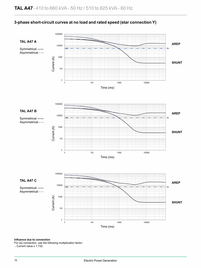
TAL A47 - 410 to 660 kVA - 50 Hz / 510 to 825 kVA - 60 Hz
For (Δ) connection, use the following multiplication factor: - Current value x 1.732.
TAL A47 A
Symmetrical --------Asymmetrical - - -
TAL A47 B
Symmetrical --------Asymmetrical - - -
Time (ms)
Time (ms)
Cur
rent
(A)
Cur
rent
(A)
TAL A47 C
Symmetrical --------Asymmetrical - - -
Time (ms)
Cur
rent
(A)
3-phase short-circuit curves at no load and rated speed (star connection Y)
C
M
Y
CM
MY
CY
CMY
K
TALA47 5676b_en.pdf 1 2019/1/9 18:05:15

17Electric Power Generation
In In
1
10
100
1000
10000
1 10 100 1000
In In
1
10
100
1000
10000
1 10 100 1000
In In
1
10
100
1000
10000
1 10 100 1000
AREP
SHUNT
AREP
SHUNT
AREP
SHUNT
TAL A47 - 410 to 660 kVA - 50 Hz / 510 to 825 kVA - 60 Hz
For (Δ) connection, use the following multiplication factor: - Current value x 1.732.
TAL A47 A
Symmetrical --------Asymmetrical - - -
TAL A47 B
Symmetrical --------Asymmetrical - - -
Time (ms)
Time (ms)
Cur
rent
(A)
Cur
rent
(A)
TAL A47 C
Symmetrical --------Asymmetrical - - -
Time (ms)
Cur
rent
(A)
3-phase short-circuit curves at no load and rated speed (star connection Y)
C
M
Y
CM
MY
CY
CMY
K
TALA47 5676b_en.pdf 1 2019/1/9 18:05:15
Electric Power Generation
In In
10
100
1000
10000
100000
1 10 100 1000
In In
1
10
100
1000
10000
100000
1 10 100 1000
AREP
SHUNT
AREP
SHUNT
AREP
SHUNT
In In
10
100
1000
10000
100000
1 10 100 1000
100000
10000
1000
100
101 10 100 1000
In
TAL A47 - 410 to 660 kVA - 50 Hz / 510 to 825 kVA - 60 Hz
TAL A47 D
Symmetrical --------Asymmetrical - - -
TAL A47 E
Symmetrical --------Asymmetrical - - -
Time (ms)
Time (ms)
Cur
rent
(A)
Cur
rent
(A)
Curves are based on a three-phase short-circuit.For other types of short-circuit, use the following multiplication factors.
3 - phase 2 - phase L / L 1 - phase L / NInstantaneous (max.) 1 0.87 1.3Continuous 1 1.5 2.2Maximum duration 1.5
TAL A47 F
Symmetrical --------Asymmetrical - - -
Time (ms)
Cur
rent
(A)
3-phase short-circuit curves at no load and rated speed (star connection Y)
C
M
Y
CM
MY
CY
CMY
K
TALA47 5676b_en.pdf 1 2019/1/9 18:05:27

18 Electric Power Generation
LB Xg 14 18TAL A47 A 1041 996 437 976 XTAL A47 B 1101 1056 471 1113 XTAL A47 C 1101 1056 471 1113 X XTAL A47 D 1201 1156 511 1240TAL A47 E 1201 1176 520 1289TAL A47 F 1221 1176 545 1372
S.A.E. P N M XBG S β° CF S.A.E. BX U X Y AH1 713 511.175 530.225 12 12 15° 15 11 1/2 352.42 333.38 8 11 39.6
1/2 713 584.2 619.125 12 14 15° 22 14 466.72 438.15 8 14 25.40 713 647.7 679.45 16 14 11° 15’ 42 18 571.5 542.92 6 17 15.7
Ø 1
20
Ø 1
15
Ø 1
10
Ø 7
5
Xr
Lr
Ø 1
15
Ø 1
06
Ø 7
5
Xr Lr M J Xr Lr M J TAL A47 A 418.3 1020 374.9 5.92 408.5 1020 376 6.18TAL A47 B 456 1080 426.6 6.77 446 1080 427.7 7.03TAL A47 C 456 1080 426.6 6.77 446 1080 427.7 7.03TAL A47 D 496 1180 477 7.5 486 1180 478.1 7.76TAL A47 E 507 1180 493.8 7.8 497 1180 494.9 8.06TAL A47 F 528 1200 525.2 8.32 518 1200 526.3 8.58
TAL A47 - 410 to 660 kVA - 50 Hz / 510 to 825 kVA - 60 Hz Single bearing general arrangement
Dimensions (mm) and weightType
Flange (mm) Flex plate (mm)
Weight (kg)L without PMG
Flange S.A.E 1/2Flange S.A.E 0
Flange S.A.E 1
CouplingFlex plate
Torsional data
Centre of gravity: Xr (mm), Rotor length: Lr (mm), Weight: M (kg), Moment of inertia: J (kgm2): (4J = MD2)Flex plate S.A.E. 14 Flex plate S.A.E. 18
Type
NOTE : upon request.
L LB
Xg
Ø B
X
Ø NØ
P
AH
610 50 710
355
12
ß
6
0 - 0,1
27
- 0,0
50- 0
,100
44.7
6
CF330
Ø 6
16
530
49
180228 244
40
20
130 90
Ø 206
0 - 1
28
89,3
62
Ø 2
35
PMG optional
AIR OUTLET
S DIA. XBG Eq. Sp. holes on Ø M P.C.D.
AIR INLET
Access to regulator
Standard cable output
Optional cableoutput
Y DIA, Qty X Eq. Sp. on Ø U P.C.D.
Access to rectifiers
456
(6-w
ire)
512
(12-
wire
)81
1 (6
-wire
)86
7 (1
2-w
ire)
506 (6-wire)560 (12-wire)
568 (6-wire) 740 (12-wire)
C
M
Y
CM
MY
CY
CMY
K
TALA47 5676b_en.pdf 1 2019/1/9 18:05:40

19Electric Power Generation
LB Xg 14 18TAL A47 A 1041 996 437 976 XTAL A47 B 1101 1056 471 1113 XTAL A47 C 1101 1056 471 1113 X XTAL A47 D 1201 1156 511 1240TAL A47 E 1201 1176 520 1289TAL A47 F 1221 1176 545 1372
S.A.E. P N M XBG S β° CF S.A.E. BX U X Y AH1 713 511.175 530.225 12 12 15° 15 11 1/2 352.42 333.38 8 11 39.6
1/2 713 584.2 619.125 12 14 15° 22 14 466.72 438.15 8 14 25.40 713 647.7 679.45 16 14 11° 15’ 42 18 571.5 542.92 6 17 15.7
Ø 1
20
Ø 1
15
Ø 1
10
Ø 7
5
Xr
Lr
Ø 1
15
Ø 1
06
Ø 7
5
Xr Lr M J Xr Lr M J TAL A47 A 418.3 1020 374.9 5.92 408.5 1020 376 6.18TAL A47 B 456 1080 426.6 6.77 446 1080 427.7 7.03TAL A47 C 456 1080 426.6 6.77 446 1080 427.7 7.03TAL A47 D 496 1180 477 7.5 486 1180 478.1 7.76TAL A47 E 507 1180 493.8 7.8 497 1180 494.9 8.06TAL A47 F 528 1200 525.2 8.32 518 1200 526.3 8.58
TAL A47 - 410 to 660 kVA - 50 Hz / 510 to 825 kVA - 60 Hz Single bearing general arrangement
Dimensions (mm) and weightType
Flange (mm) Flex plate (mm)
Weight (kg)L without PMG
Flange S.A.E 1/2Flange S.A.E 0
Flange S.A.E 1
CouplingFlex plate
Torsional data
Centre of gravity: Xr (mm), Rotor length: Lr (mm), Weight: M (kg), Moment of inertia: J (kgm2): (4J = MD2)Flex plate S.A.E. 14 Flex plate S.A.E. 18
Type
NOTE : upon request.
L LB
Xg
Ø B
X
Ø NØ
P
AH
610 50 710
355
12
ß
6
0 - 0,1
27
- 0,0
50- 0
,100
44.7
6
CF330
Ø 6
16
530
49
180228 244
40
20
130 90
Ø 206
0 - 1
28
89,3
62
Ø 2
35
PMG optional
AIR OUTLET
S DIA. XBG Eq. Sp. holes on Ø M P.C.D.
AIR INLET
Access to regulator
Standard cable output
Optional cableoutput
Y DIA, Qty X Eq. Sp. on Ø U P.C.D.
Access to rectifiers
456
(6-w
ire)
512
(12-
wire
)81
1 (6
-wire
)86
7 (1
2-w
ire)
506 (6-wire)560 (12-wire)
568 (6-wire) 740 (12-wire)
C
M
Y
CM
MY
CY
CMY
K
TALA47 5676b_en.pdf 1 2019/1/9 18:05:40
Electric Power Generation
Phase 3 ph. 3 ph. 3 ph. 3 ph.Y 380V 400V 415V 440V 380V 400V 415V 440V 380V 400V 415V 440V 380V 400V 415V 440V
∆ 220V 230V 240V 220V 230V 240V 220V 230V 240V 220V 230V 240VYY (*) 220V 220V 220V 220V
TAL A49 B kVA 750 750 750 680 680 680 680 620 800 800 800 750 825 825 825 785
kW 600 600 600 544 544 544 544 496 640 640 640 600 660 660 660 628
TAL A49 C kVA 820 820 820 810 745 745 745 735 870 870 870 860 910 910 910 890
kW 656 656 656 648 596 596 596 588 696 696 696 688 728 728 728 712
TAL A49 D kVA 910 910 910 820 830 830 830 745 965 965 965 870 1010 1010 1010 900
kW 728 728 728 656 664 664 664 596 772 772 772 696 808 808 808 720
TAL A49 E kVA 1000 1000 1000 950 910 910 910 865 1060 1060 1060 1005 1100 1100 1100 1045
kW 800 800 800 760 728 728 728 692 848 848 848 804 880 880 880 836
Phase 3 ph. 3 ph. 3 ph. 3 ph.Y 380V 416V 440V 480V 380V 416V 440V 480V 380V 416V 440V 480V 380V 416V 440V 480V
∆ 220V 240V 220V 240V 220V 240V 220V 240VYY (*) 208V 220V 240V 208V 220V 240V 208V 220V 240V 208V 220V 240V
TAL A49 B kVA 745 815 860 940 670 730 775 845 790 865 910 995 820 895 945 1030kW 596 652 688 752 536 584 620 676 632 692 728 796 656 716 756 824
TAL A49 C kVA 815 890 940 1025 740 810 855 935 865 945 995 1085 895 980 1040 1130kW 652 712 752 820 592 648 684 748 692 756 796 868 716 784 832 904
TAL A49 D kVA 905 990 1045 1140 825 900 950 1035 960 1050 1110 1210 1000 1090 1155 1255kW 724 792 836 912 660 720 760 828 768 840 888 968 800 872 924 1004
TAL A49 E kVA 990 1083 1146 1250 900 985 1045 1140 1050 1150 1215 1325 1089 1192 1260 1375kW 792 866 917 1000 720 788 836 912 840 920 972 1060 871 954 1008 1100
TAL A49 - 750 to 1000 kVA - 50 Hz / 940 to 1250 kVA - 60 Hz General characteristics
Ratings 50 Hz - 1500 R.P.M.
Ratings 60 Hz - 1800 R.P.M.
Insulation class H Excitation system 6-wire SHUNT AREP / PMGWinding pitch 2/3 (wind.6S - 6-wire / wind.6 - 12-wire) AVR type R150 R180Number of wires 6-wire (12-wire option) Excitation system 12-wire (option) SHUNT AREP / PMGProtection IP 23 AVR type R250 R180Altitude ≤ 1000 m Voltage regulation (*) ± 1 %Overspeed 2250 R.P.M. Total Harmonic Distortion THD (**) in no-load < 3.5 %
3/s) 1 Total Harmonic Distortion THD (**) in linear load < 5 %3/s) 1.2 Waveform: NEMA = TIF (**) < 50
AREP Short-circuit current = 2.7 In : 5 second Waveform: I.E.C. = THF (**) < 2%(*) Steady state (**) Total harmonic distortion between phases, no-load or on-load (non-distorting)
kVA / kW - P.F. = 0.8Duty / T° C Continuous / 40 °C Continuous / 40 °C Stand-by / 40 °C Stand-by / 27 °CClass / T° K H / 125° K F / 105° K H / 150° K H / 163° K
kVA / kW - P.F. = 0.8Duty / T° C Continuous / 40 °C Continuous / 40 °C Stand-by / 40 °C Stand-by / 27 °CClass / T° K H / 125° K F / 105° K H / 150° K H / 163° K
(*) 12-wire option
(*) 12-wire option
C
M
Y
CM
MY
CY
CMY
K
TALA49 5677b_en.pdf 1 2019/1/9 18:06:14

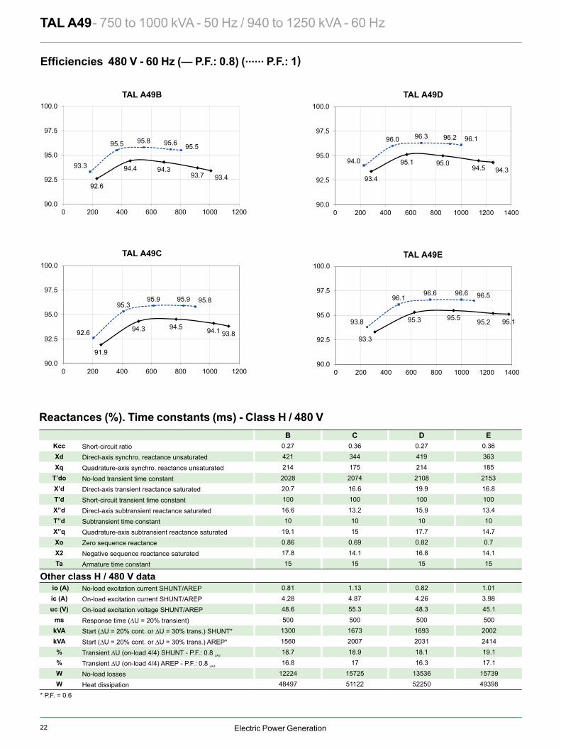
20 Electric Power Generation
93.794.094.594.6
92.9
95.996.096.195.8
93.6
90.0
92.5
95.0
97.5
100.0
0 200 400 600 800 1000
93.293.694.494.8
93.6
95.595.796.096.0
94.4
90.0
92.5
95.0
97.5
100.0
0 200 400 600 800 1000
TAL A49B
TAL A49C
94.194.495.195.4
94.3
96.196.296.596.4
94.9
90.0
92.5
95.0
97.5
100.0
0 200 400 600 800 1000 1200
TAL A49D
95.095.295.695.6
94.1
96.696.796.896.5
94.7
90.0
92.5
95.0
97.5
100.0
0 200 400 600 800 1000 1200
TAL A49E
B C D EKcc 0.28 0.37 0.28 0.38Xd 403 330 402 348Xq 205 168 205 177
T’do 2028 2074 2108 2153X’d 19.8 15.9 19 16.1T’d 100 100 100 100X”d 15.9 12.7 15.2 12.9T”d 10 10 10 10X”q 18.3 14.4 16.9 14.1Xo 0.82 0.66 0.79 0.67X2 17.1 13.5 16.1 13.5Ta 15 15 15 15
io (A) 0.81 1.13 0.83 1.01ic (A) 4.15 4.76 4.15 3.9uc (V) 47.1 53.8 46.9 44.1
ms 500 500 500 500kVA 1084 1387 1412 1671kVA 1301 1664 1695 2002% 18.1 18.5 17.5 18.6% 16.3 16.6 15.7 16.7W 7774 10303 8702 10355W 39606 41702 42589 39986
TAL A49 - 750 to 1000 kVA - 50 Hz / 940 to 1250 kVA - 60 Hz
* P.F. = 0.6
— P.F.: 0.8) (...... P.F.: 1)
Short-circuit ratioDirect-axis synchro. reactance unsaturatedQuadrature-axis synchro. reactance unsaturatedNo-load transient time constantDirect-axis transient reactance saturatedShort-circuit transient time constantDirect-axis subtransient reactance saturatedSubtransient time constantQuadrature-axis subtransient reactance saturatedZero sequence reactanceNegative sequence reactance saturatedArmature time constant
Other class H / 400 V dataNo-load excitation current SHUNT/AREPOn-load excitation current SHUNT/AREPOn-load excitation voltage SHUNT/AREPResponse time (∆U = 20% transient)Start (∆U = 20% cont. or ∆U = 30% trans.) SHUNT*Start (∆U = 20% cont. or ∆U = 30% trans.) AREP*Transient ∆U (on-load 4/4) SHUNT - P.F.: 0.8 LAG
Transient ∆U (on-load 4/4) AREP - P.F.: 0.8 LAG
No-load lossesHeat dissipation
Reactances (%). Time constants (ms) - Class H / 400 V
C
M
Y
CM
MY
CY
CMY
K
TALA49 5677b_en.pdf 1 2019/1/9 18:06:39
21Electric Power Generation
93.794.094.594.6
92.9
95.996.096.195.8
93.6
90.0
92.5
95.0
97.5
100.0
0 200 400 600 800 1000
93.293.694.494.8
93.6
95.595.796.096.0
94.4
90.0
92.5
95.0
97.5
100.0
0 200 400 600 800 1000
TAL A49B
TAL A49C
94.194.495.195.4
94.3
96.196.296.596.4
94.9
90.0
92.5
95.0
97.5
100.0
0 200 400 600 800 1000 1200
TAL A49D
95.095.295.695.6
94.1
96.696.796.896.5
94.7
90.0
92.5
95.0
97.5
100.0
0 200 400 600 800 1000 1200
TAL A49E
B C D EKcc 0.28 0.37 0.28 0.38Xd 403 330 402 348Xq 205 168 205 177
T’do 2028 2074 2108 2153X’d 19.8 15.9 19 16.1T’d 100 100 100 100X”d 15.9 12.7 15.2 12.9T”d 10 10 10 10X”q 18.3 14.4 16.9 14.1Xo 0.82 0.66 0.79 0.67X2 17.1 13.5 16.1 13.5Ta 15 15 15 15
io (A) 0.81 1.13 0.83 1.01ic (A) 4.15 4.76 4.15 3.9uc (V) 47.1 53.8 46.9 44.1
ms 500 500 500 500kVA 1084 1387 1412 1671kVA 1301 1664 1695 2002% 18.1 18.5 17.5 18.6% 16.3 16.6 15.7 16.7W 7774 10303 8702 10355W 39606 41702 42589 39986
TAL A49 - 750 to 1000 kVA - 50 Hz / 940 to 1250 kVA - 60 Hz
* P.F. = 0.6
— P.F.: 0.8) (...... P.F.: 1)
Short-circuit ratioDirect-axis synchro. reactance unsaturatedQuadrature-axis synchro. reactance unsaturatedNo-load transient time constantDirect-axis transient reactance saturatedShort-circuit transient time constantDirect-axis subtransient reactance saturatedSubtransient time constantQuadrature-axis subtransient reactance saturatedZero sequence reactanceNegative sequence reactance saturatedArmature time constant
Other class H / 400 V dataNo-load excitation current SHUNT/AREPOn-load excitation current SHUNT/AREPOn-load excitation voltage SHUNT/AREPResponse time (∆U = 20% transient)Start (∆U = 20% cont. or ∆U = 30% trans.) SHUNT*Start (∆U = 20% cont. or ∆U = 30% trans.) AREP*Transient ∆U (on-load 4/4) SHUNT - P.F.: 0.8 LAG
Transient ∆U (on-load 4/4) AREP - P.F.: 0.8 LAG
No-load lossesHeat dissipation
Reactances (%). Time constants (ms) - Class H / 400 V
C
M
Y
CM
MY
CY
CMY
K
TALA49 5677b_en.pdf 1 2019/1/9 18:06:39
Electric Power Generation
0%
5%
10%
15%
20%
25%
30%
0 200 400 600 800 1000 1200 1400 1600 1800 2000 2200
0%
5%
10%
15%
20%
25%
30%
0 200 400 600 800 1000 1200 1400 1600 1800 2000 2200
0%
5%
10%
15%
20%
25%
30%
0 200 400 600 800 1000 1200 1400 1600 1800 2000 2200
0%
5%
10%
15%
20%
25%
30%
0 200 400 600 800 1000 1200 1400 1600 1800 2000 2200
0%
5%
10%
15%
20%
25%
30%
0 200 400 600 800 1000 1200 1400 1600 1800 2000 2200
0%
5%
10%
15%
20%
25%
30%
0 200 400 600 800 1000 1200 1400 1600 1800 2000 2200
B C ED
B C ED B C ED
B C ED B C ED
B C ED
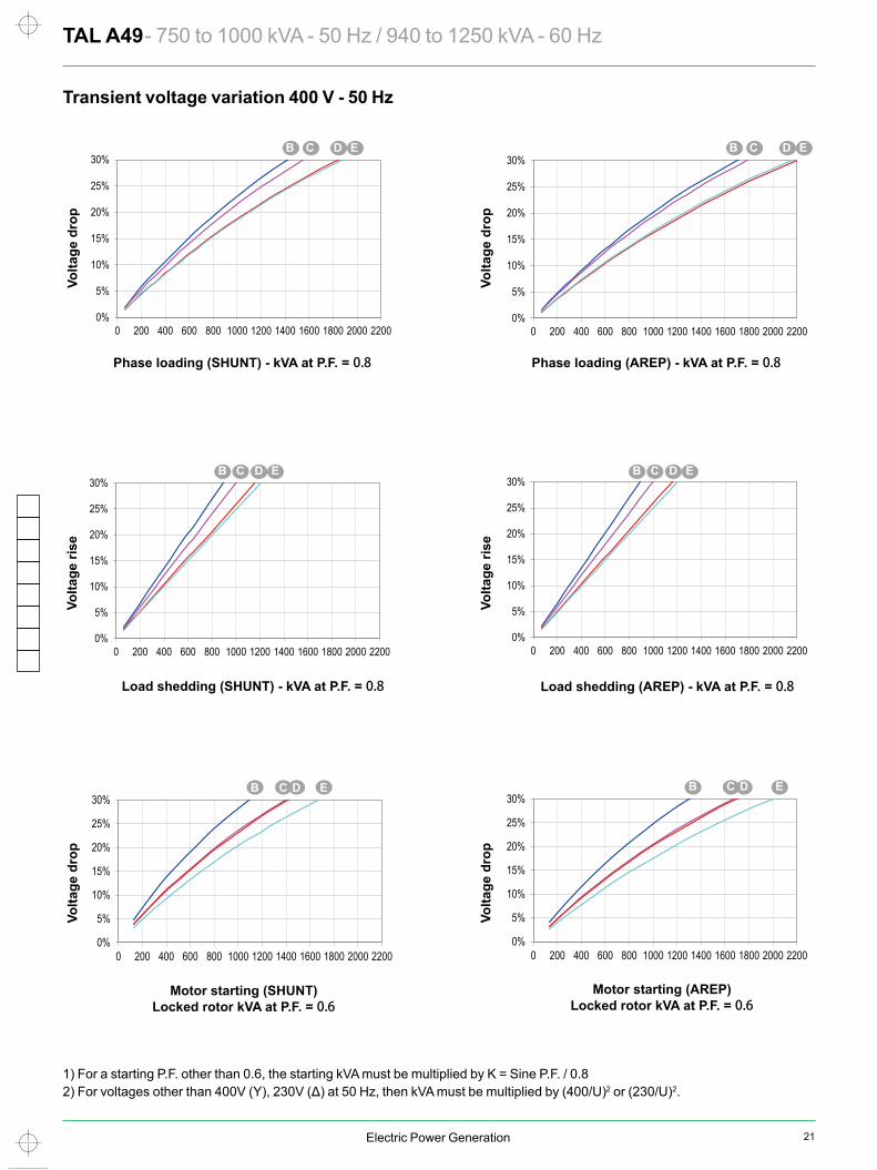
TAL A49 - 750 to 1000 kVA - 50 Hz / 940 to 1250 kVA - 60 Hz Transient voltage variation 400 V - 50 Hz
1) For a starting P.F. other than 0.6, the starting kVA must be multiplied by K = Sine P.F. / 0.82) For voltages other than 400V (Y), 230V (Δ) at 50 Hz, then kVA must be multiplied by (400/U)2 or (230/U)2.
Phase loading (SHUNT) - kVA at P.F. = 0.8 Phase loading (AREP) - kVA at P.F. = 0.8
Load shedding (SHUNT) - kVA at P.F. = 0.8 Load shedding (AREP) - kVA at P.F. = 0.8
Motor starting (SHUNT) Locked rotor kVA at P.F. = 0.6
Motor starting (AREP) Locked rotor kVA at P.F. = 0.6
Volta
ge d
rop
Volta
ge d
rop
Volta
ge ri
se
Volta
ge ri
se
Volta
ge d
rop
Volta
ge d
rop
C
M
Y
CM
MY
CY
CMY
K
TALA49 5677b_en.pdf 1 2019/1/9 18:07:02
22 Electric Power Generation
95.195.295.595.3
93.3
96.596.696.696.1
93.8
90.0
92.5
95.0
97.5
100.0
0 200 400 600 800 1000 1200 1400
94.394.595.095.1
93.4
96.196.296.396.0
94.0
90.0
92.5
95.0
97.5
100.0
0 200 400 600 800 1000 1200 1400
93.894.194.594.3
91.9
95.895.995.995.3
92.6
90.0
92.5
95.0
97.5
100.0
0 200 400 600 800 1000 1200
93.493.794.394.4
92.6
95.595.695.895.5
93.3
90.0
92.5
95.0
97.5
100.0
0 200 400 600 800 1000 1200
B C D EKcc 0.27 0.36 0.27 0.36Xd 421 344 419 363Xq 214 175 214 185
T’do 2028 2074 2108 2153X’d 20.7 16.6 19.9 16.8T’d 100 100 100 100X”d 16.6 13.2 15.9 13.4T”d 10 10 10 10X”q 19.1 15 17.7 14.7Xo 0.86 0.69 0.82 0.7X2 17.8 14.1 16.8 14.1Ta 15 15 15 15
io (A) 0.81 1.13 0.82 1.01ic (A) 4.28 4.87 4.26 3.98uc (V) 48.6 55.3 48.3 45.1
ms 500 500 500 500kVA 1300 1673 1693 2002kVA 1560 2007 2031 2414% 18.7 18.9 18.1 19.1% 16.8 17 16.3 17.1W 12224 15725 13536 15739W 48497 51122 52250 49398
TAL A49B
TAL A49C
TAL A49D
TAL A49E
TAL A49 - 750 to 1000 kVA - 50 Hz / 940 to 1250 kVA - 60 Hz
Short-circuit ratioDirect-axis synchro. reactance unsaturatedQuadrature-axis synchro. reactance unsaturatedNo-load transient time constantDirect-axis transient reactance saturatedShort-circuit transient time constantDirect-axis subtransient reactance saturatedSubtransient time constantQuadrature-axis subtransient reactance saturatedZero sequence reactanceNegative sequence reactance saturatedArmature time constant
Other class H / 480 V dataNo-load excitation current SHUNT/AREPOn-load excitation current SHUNT/AREPOn-load excitation voltage SHUNT/AREPResponse time (∆U = 20% transient)Start (∆U = 20% cont. or ∆U = 30% trans.) SHUNT*Start (∆U = 20% cont. or ∆U = 30% trans.) AREP*
Transient ∆U (on-load 4/4) SHUNT - P.F.: 0.8 LAG
Transient ∆U (on-load 4/4) AREP - P.F.: 0.8 LAG
No-load lossesHeat dissipation
Reactances (%). Time constants (ms) - Class H / 480 V
* P.F. = 0.6
— P.F.: 0.8) (...... P.F.: 1)
C
M
Y
CM
MY
CY
CMY
K
TALA49 5677b_en.pdf 1 2019/1/9 18:07:27
23Electric Power Generation
95.195.295.595.3
93.3
96.596.696.696.1
93.8
90.0
92.5
95.0
97.5
100.0
0 200 400 600 800 1000 1200 1400
94.394.595.095.1
93.4
96.196.296.396.0
94.0
90.0
92.5
95.0
97.5
100.0
0 200 400 600 800 1000 1200 1400
93.894.194.594.3
91.9
95.895.995.995.3
92.6
90.0
92.5
95.0
97.5
100.0
0 200 400 600 800 1000 1200
93.493.794.394.4
92.6
95.595.695.895.5
93.3
90.0
92.5
95.0
97.5
100.0
0 200 400 600 800 1000 1200
B C D EKcc 0.27 0.36 0.27 0.36Xd 421 344 419 363Xq 214 175 214 185
T’do 2028 2074 2108 2153X’d 20.7 16.6 19.9 16.8T’d 100 100 100 100X”d 16.6 13.2 15.9 13.4T”d 10 10 10 10X”q 19.1 15 17.7 14.7Xo 0.86 0.69 0.82 0.7X2 17.8 14.1 16.8 14.1Ta 15 15 15 15
io (A) 0.81 1.13 0.82 1.01ic (A) 4.28 4.87 4.26 3.98uc (V) 48.6 55.3 48.3 45.1
ms 500 500 500 500kVA 1300 1673 1693 2002kVA 1560 2007 2031 2414% 18.7 18.9 18.1 19.1% 16.8 17 16.3 17.1W 12224 15725 13536 15739W 48497 51122 52250 49398
TAL A49B
TAL A49C
TAL A49D
TAL A49E
TAL A49 - 750 to 1000 kVA - 50 Hz / 940 to 1250 kVA - 60 Hz
Short-circuit ratioDirect-axis synchro. reactance unsaturatedQuadrature-axis synchro. reactance unsaturatedNo-load transient time constantDirect-axis transient reactance saturatedShort-circuit transient time constantDirect-axis subtransient reactance saturatedSubtransient time constantQuadrature-axis subtransient reactance saturatedZero sequence reactanceNegative sequence reactance saturatedArmature time constant
Other class H / 480 V dataNo-load excitation current SHUNT/AREPOn-load excitation current SHUNT/AREPOn-load excitation voltage SHUNT/AREPResponse time (∆U = 20% transient)Start (∆U = 20% cont. or ∆U = 30% trans.) SHUNT*Start (∆U = 20% cont. or ∆U = 30% trans.) AREP*
Transient ∆U (on-load 4/4) SHUNT - P.F.: 0.8 LAG
Transient ∆U (on-load 4/4) AREP - P.F.: 0.8 LAG
No-load lossesHeat dissipation
Reactances (%). Time constants (ms) - Class H / 480 V
* P.F. = 0.6
— P.F.: 0.8) (...... P.F.: 1)
C
M
Y
CM
MY
CY
CMY
K
TALA49 5677b_en.pdf 1 2019/1/9 18:07:27
Electric Power Generation
0%
5%
10%
15%
20%
25%
30%
0 300 600 900 1200 1500 1800 2100 2400 2700
0%
5%
10%
15%
20%
25%
30%
0 300 600 900 1200 1500 1800 2100 2400 2700
0%
5%
10%
15%
20%
25%
30%
0 300 600 900 1200 1500 1800 2100 2400 2700
0%
5%
10%
15%
20%
25%
30%
0 300 600 900 1200 1500 1800 2100 2400 2700
0%
5%
10%
15%
20%
25%
30%
0 300 600 900 1200 1500 1800 2100 2400 2700
0%
5%
10%
15%
20%
25%
30%
0 300 600 900 1200 1500 1800 2100 2400 2700
B C ED
B C ED B C ED
B C ED B C ED
B C ED
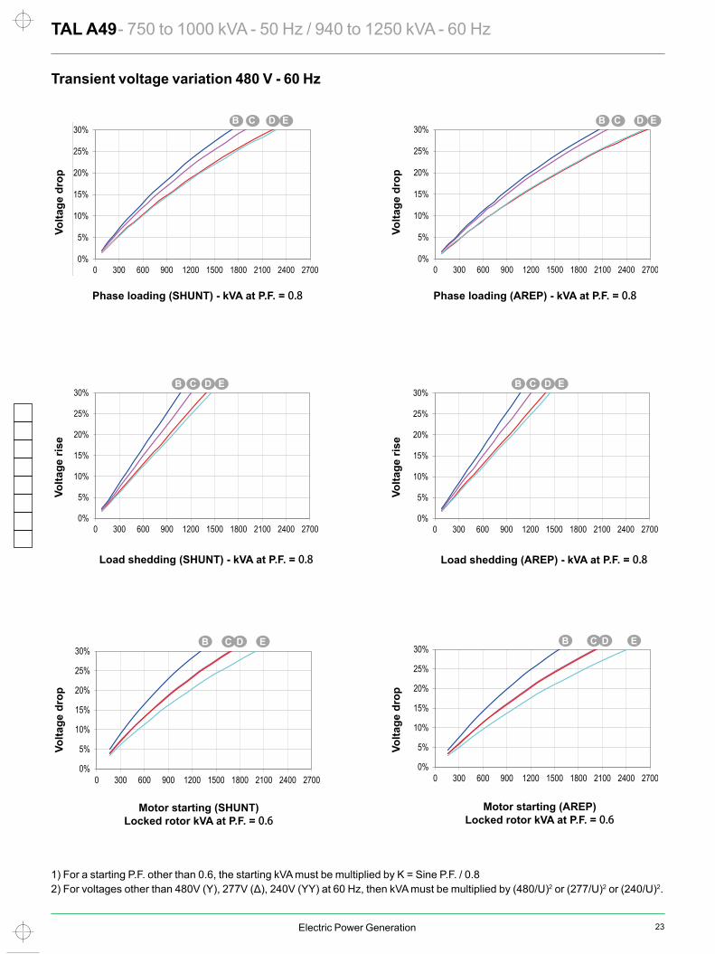
TAL A49 - 750 to 1000 kVA - 50 Hz / 940 to 1250 kVA - 60 Hz Transient voltage variation 480 V - 60 Hz
1) For a starting P.F. other than 0.6, the starting kVA must be multiplied by K = Sine P.F. / 0.82) For voltages other than 480V (Y), 277V (Δ), 240V (YY) at 60 Hz, then kVA must be multiplied by (480/U)2 or (277/U)2 or (240/U)2.
Phase loading (SHUNT) - kVA at P.F. = 0.8 Phase loading (AREP) - kVA at P.F. = 0.8
Load shedding (SHUNT) - kVA at P.F. = 0.8 Load shedding (AREP) - kVA at P.F. = 0.8
Motor starting (SHUNT) Locked rotor kVA at P.F. = 0.6
Motor starting (AREP) Locked rotor kVA at P.F. = 0.6
Volta
ge d
rop
Volta
ge d
rop
Volta
ge ri
se
Volta
ge ri
se
Volta
ge d
rop
Volta
ge d
rop
C
M
Y
CM
MY
CY
CMY
K
TALA49 5677b_en.pdf 1 2019/1/9 18:07:50
24 Electric Power Generation
In In
10
100
1000
10000
100000
1 10 100 1000
In In
10
100
1000
10000
100000
1 10 100 1000
AREP
SHUNT
AREP
SHUNT
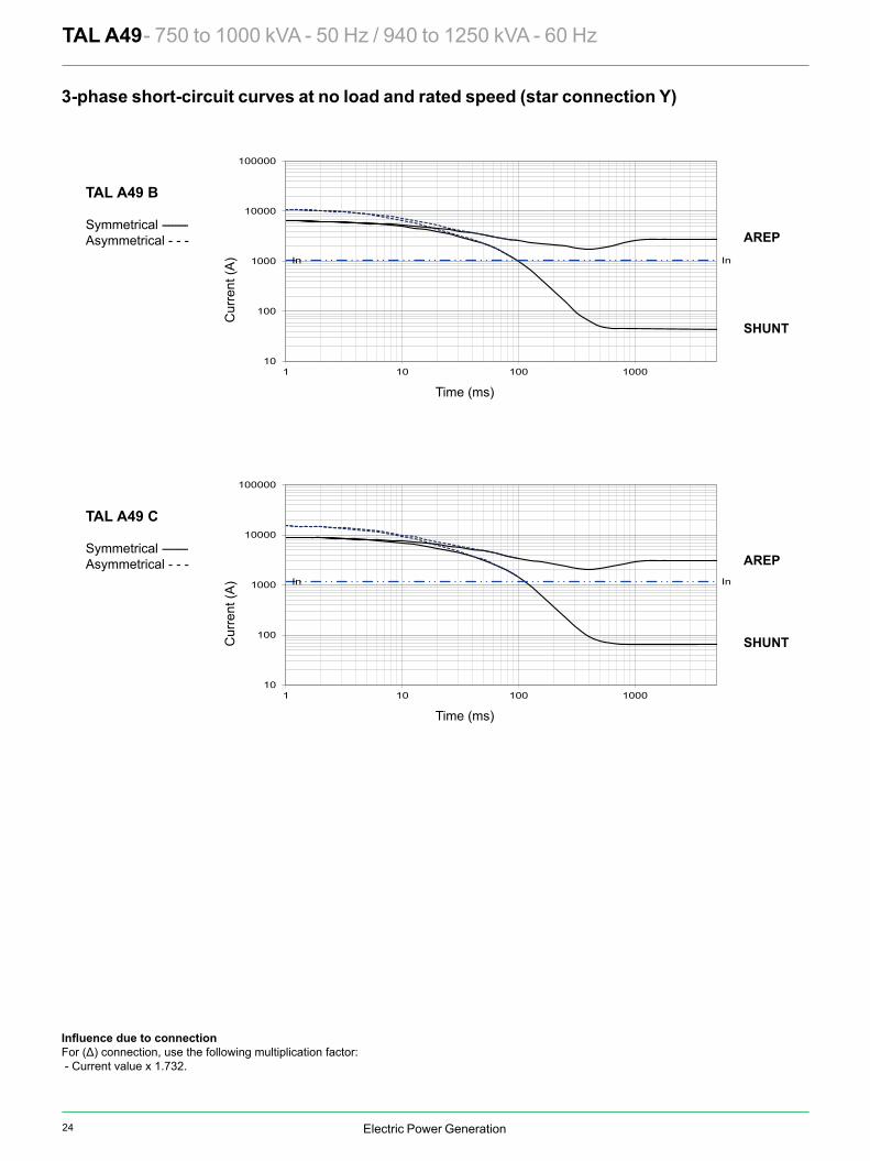
TAL A49 - 750 to 1000 kVA - 50 Hz / 940 to 1250 kVA - 60 Hz
For (Δ) connection, use the following multiplication factor: - Current value x 1.732.
TAL A49 B
Symmetrical --------Asymmetrical - - -
TAL A49 C
Symmetrical --------Asymmetrical - - -
Time (ms)
Time (ms)
Cur
rent
(A)
Cur
rent
(A)
3-phase short-circuit curves at no load and rated speed (star connection Y)
C
M
Y
CM
MY
CY
CMY
K
TALA49 5677b_en.pdf 1 2019/1/9 18:08:10
25Electric Power Generation
In In
10
100
1000
10000
100000
1 10 100 1000
In In
10
100
1000
10000
100000
1 10 100 1000
AREP
SHUNT
AREP
SHUNT
TAL A49 - 750 to 1000 kVA - 50 Hz / 940 to 1250 kVA - 60 Hz
For (Δ) connection, use the following multiplication factor: - Current value x 1.732.
TAL A49 B
Symmetrical --------Asymmetrical - - -
TAL A49 C
Symmetrical --------Asymmetrical - - -
Time (ms)
Time (ms)
Cur
rent
(A)
Cur
rent
(A)
3-phase short-circuit curves at no load and rated speed (star connection Y)
C
M
Y
CM
MY
CY
CMY
K
TALA49 5677b_en.pdf 1 2019/1/9 18:08:10
Electric Power Generation
In In
10
100
1000
10000
100000
1 10 100 1000
In In
10
100
1000
10000
100000
1 10 100 1000
AREP
SHUNT
AREP
SHUNT
In
1 10 100 1000
TAL A49 - 750 to 1000 kVA - 50 Hz / 940 to 1250 kVA - 60 Hz
TAL A49 D
Symmetrical --------Asymmetrical - - -
TAL A49 E
Symmetrical --------Asymmetrical - - -
Time (ms)
Time (ms)
Cur
rent
(A)
Cur
rent
(A)
Curves are based on a three-phase short-circuit.For other types of short-circuit, use the following multiplication factors.
3 - phase 2 - phase L / L 1 - phase L / NInstantaneous (max.) 1 0.87 1.3Continuous 1 1.5 2.2Maximum duration 1.5
3-phase short-circuit curves at no load and rated speed (star connection Y)
C
M
Y
CM
MY
CY
CMY
K
TALA49 5677b_en.pdf 1 2019/1/9 18:08:31

26 Electric Power Generation
LB C Xg 14 18TAL A49 B 1372 1331 650 629 1574 XTAL A49 C 1372 1331 650 636 1635 XTAL A49 D 1462 1421 650 673 1788 X XTAL A49 E 1462 1421 650 681 1837 X
S.A.E. P N M LC XBG W ß° S.A.E. BX U X Y AH1 773 511.175 530.225 228.5 12 6 15° 14 466.7 438.15 8 14 25.4
1/2 773 584.2 619.125 228.5 12 6 15° 18 571.5 542.92 6 17 15.7 0 773 647.7 679.45 228.5 16 6 11° 15’ 00 883 787.4 850.9 245 16 7 11°15’
Xr Lr M J Xr Lr M J TAL A49 B 626 1345 602 9.61 614 1345 604 9.87TAL A49 C 634 1345 628 10.16 622 1345 630 10.42TAL A49 D 671 1435 684 11.12 659 1435 686 11.38TAL A49 E 681 1435 701 11.48 669 1435 703 11.74
Xr
Ø 1
30
Ø 1
35
Ø 1
45
Ø 1
45
Ø 1
49
Ø 1
45Ø
140
Ø 1
15Ø
90
Lr
TAL A49 - 750 to 1000 kVA - 50 Hz / 940 to 1250 kVA - 60 Hz Single bearing general arrangement
Dimensions (mm) and weightType
Flange (mm) Flex plate (mm)
Weight (kg)L without PMG
Flange S.A.E 1/2Flange S.A.E 1
CouplingFlex plate
Flange S.A.E 00Flange S.A.E 0
PMG optional
L LB
Xg
AIR OUTLET
Ø B
XØ P
Ø N
AH620
686 786
608
40
0
1008
12
S DIA. Qty XBG as shown on Ø M
ß°
Access to rotating diodes
0 - 0.1
27
- 0.0
50- 0
.100
6
W
620
AIR INLETC
45.515.5
25990
336.5
35
10
Access to regulator
Access to terminals
110
0 - 1
Y DIA, Qty X Eq. Sp. on Ø U.
Cable output
Cable output
LC
Torsional data
Centre of gravity: Xr (mm), Rotor length: Lr (mm), Weight: M (kg), Moment of inertia: J (kgm2): (4J = MD2)Flex plate S.A.E. 14 Flex plate S.A.E. 18
Type
NOTE : upon request.
C
M
Y
CM
MY
CY
CMY
K
TALA49 5677b_en.pdf 1 2019/1/9 18:08:53
Electric Power Generation
LB C Xg 14 18TAL A49 B 1372 1331 650 629 1574 XTAL A49 C 1372 1331 650 636 1635 XTAL A49 D 1462 1421 650 673 1788 X XTAL A49 E 1462 1421 650 681 1837 X
S.A.E. P N M LC XBG W ß° S.A.E. BX U X Y AH1 773 511.175 530.225 228.5 12 6 15° 14 466.7 438.15 8 14 25.4
1/2 773 584.2 619.125 228.5 12 6 15° 18 571.5 542.92 6 17 15.7 0 773 647.7 679.45 228.5 16 6 11° 15’ 00 883 787.4 850.9 245 16 7 11°15’
Xr Lr M J Xr Lr M J TAL A49 B 626 1345 602 9.61 614 1345 604 9.87TAL A49 C 634 1345 628 10.16 622 1345 630 10.42TAL A49 D 671 1435 684 11.12 659 1435 686 11.38TAL A49 E 681 1435 701 11.48 669 1435 703 11.74
Xr
Ø 1
30
Ø 1
35
Ø 1
45
Ø 1
45
Ø 1
49
Ø 1
45Ø
140
Ø 1
15Ø
90
Lr
TAL A49 - 750 to 1000 kVA - 50 Hz / 940 to 1250 kVA - 60 Hz Single bearing general arrangement
Dimensions (mm) and weightType
Flange (mm) Flex plate (mm)
Weight (kg)L without PMG
Flange S.A.E 1/2Flange S.A.E 1
CouplingFlex plate
Flange S.A.E 00Flange S.A.E 0
PMG optional
L LB
Xg
AIR OUTLET
Ø B
XØ P
Ø N
AH620
686 786
608
40
0
1008
12
S DIA. Qty XBG as shown on Ø M
ß°
Access to rotating diodes
0 - 0.1
27
- 0.0
50- 0
.100
6
W
620
AIR INLETC
45.515.5
25990
336.5
35
10
Access to regulator
Access to terminals
110
0 - 1
Y DIA, Qty X Eq. Sp. on Ø U.
Cable output
Cable output
LC
Torsional data
Centre of gravity: Xr (mm), Rotor length: Lr (mm), Weight: M (kg), Moment of inertia: J (kgm2): (4J = MD2)Flex plate S.A.E. 14 Flex plate S.A.E. 18
Type
NOTE : upon request.
C
M
Y
CM
MY
CY
CMY
K
TALA49 5677b_en.pdf 1 2019/1/9 18:08:53

5376 en - 2019.02 / e – AP
www.nidecautomation.com
Moteurs Leroy-Somer SAS. Headquarters: Bd Marcellin Leroy, CS 10015, 16915 Angoulême Cedex 9, France. Share Capital: 65 800 512 €, RCS Angoulême 338 567 258.
Connect with us at:
Twitter.com/EPG_Alternators
Facebook.com/LeroySomer.EPG
Youtube.com/LeroySomerOfficiel
Linkedin.com/company/44575
WeChat.com/Leroy-SomerEPG
Scan the QR Code for more information
Leroy Somer WeChat