low-voltage fuse systems - lc automation · 1/49 cylindrical fuse links sitor 1/50 bases for...
TRANSCRIPT
1/1
Low-VoltageFuse Systems
1
NEOZED fuse system 1/4 NEOZED fuse links1/4 NEOZED fuse links
SILIZED (utilization category gR)1/5 NEOZED fuse bases1/11 NEOZED fuse disconnectors1/12 MINIZED switch disconnectors
DIAZED fuse system 1/14 DIAZED fuse links1/15 DIAZED fuse links
SILIZED (utilization category gR)1/16 DIAZED fuse bases
LV HRC fuse system 1/21 LV HRC fuse links1/28 LV HRC fuse links SITOR1/33 LV HRC fuse bases1/36 LV HRC signal detectors1/37 LV HRC fuse switch disconnectors
Cylindrical fuse system 1/48 Cylindrical fuse links1/49 Cylindrical fuse links SITOR1/50 Bases for cylindrical fuses
SITOR fuse links for special applications
1/51 For rectifiers in electrolysis systems1/52 For SITOR thyristor sets1/52 For railway supply rectifiers
bet_01kapiteltitel.fm Seite 1 Mittwoch, 16. Februar 2005 9:19 09

1/2
Low-Voltage Fuse Systems
Protection against overload and short circuit for cables, devices
and plants - for the prevention of damage and consequential
costs.
Our low-voltage fuses offer complete protection.
When things start hotting up:
bet_01seite2.fm Seite 2 Mittwoch, 16. Februar 2005 9:20 09
1/3
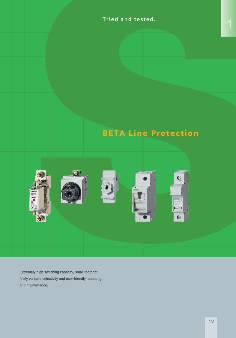
Tried and tested.
Extremely high switching capacity, small footprint,
finely variable selectivity and user-friendly mounting
and maintenance.
BETA Line Protection
1
bet_01seite3.fm Seite 3 Mittwoch, 16. Februar 2005 9:20 09

NEOZED fuse links
1/4
NEOZED Fuse SystemLow-Voltage Fuse Systems
Siemens ET B1 · 2005
■ Selection and ordering data
■ Selection and ordering data
Size In Identification color
Order No. Price PG Weight1 item
PS*/P. unit
A 1 item kg Items
Rated voltage 400 V AC/250 V DC, utilization category gL/gGConsumer packing, package of 10
D01 2 pink 5SE2 302 016 0.006 104 brown 5SE2 304 016 0.006 106 green 5SE2 306 016 0.006 10
10 red 5SE2 310 016 0.007 1013 black 5SE2 013-2A 016 0.007 1016 gray 5SE2 316 016 0.007 10
D02 20 blue 5SE2 320 016 0.012 1025 yellow 5SE2 325 016 0.013 1032 black 5SE2 332 016 0.014 10
35 black 5SE2 335 016 0.014 1040 black 5SE2 340 016 0.014 1050 white 5SE2 350 016 0.015 10
63 copper 5SE2 363 016 0.016 10
D03 80 silver 5SE2 280 016 0.039 10100 red 5SE2 300 016 0.042 10
Version for Italy only (no approvals)
D01 20 blue 5SE2 820 016 0.011 1025 yellow 5SE2 825 016 0.012 10
NEOZED fuse links SILIZED(utilization category gR)
Size In Order No. Price PG Weight PS*/P. unit1 item
A 1 item kg Items
Rated voltage 400 V AC/250 V DC, utilization category gRConsumer packing, package of 10
D01 10 5SE1 310 016 0.006 1016 5SE1 316 016 0.007 10
D02 20 5SE1 320 016 0.012 1025 5SE1 325 016 0.012 1035 5SE1 335 016 0.012 10
50 5SE1 350 016 0.013 1063 5SE1 363 016 0.014 10
Low-Voltage Fuse Systems
* You can order this quantity or a multiple thereof.
NEOZED fuse bases
1/5
NEOZED Fuse SystemLow-Voltage Fuse Systems 1
345678910
1213
Siemens ET B1 · 2005
■ Selection and ordering data
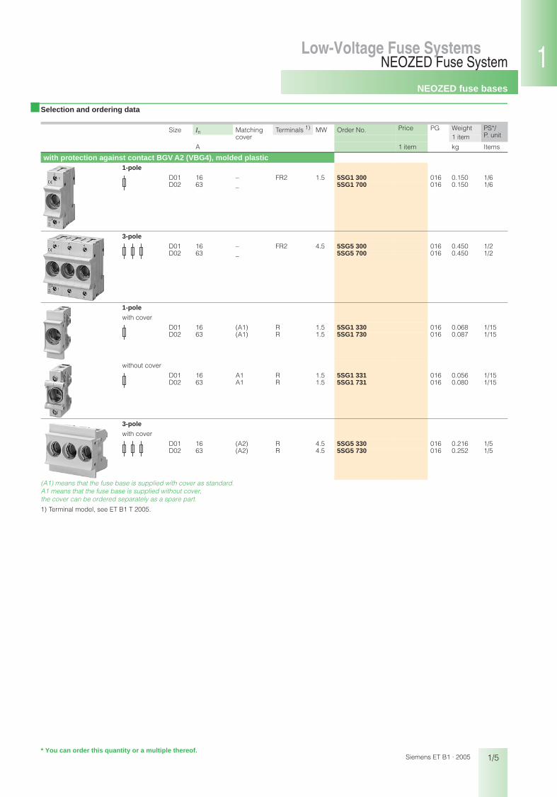
(A1) means that the fuse base is supplied with cover as standard. A1 means that the fuse base is supplied without cover, the cover can be ordered separately as a spare part.
1) Terminal model, see ET B1 T 2005.
Size In Matching Terminals 1) MW Order No. Price PG Weight PS*/P. unitcover 1 item
A 1 item kg Items
with protection against contact BGV A2 (VBG4), molded plastic1-pole
D01 16 – FR2 1.5 5SG1 300 016 0.150 1/6D02 63 – 5SG1 700 016 0.150 1/6
3-pole
D01 16 – FR2 4.5 5SG5 300 016 0.450 1/2D02 63 – 5SG5 700 016 0.450 1/2
1-pole
with cover
D01 16 (A1) R 1.5 5SG1 330 016 0.068 1/15D02 63 (A1) R 1.5 5SG1 730 016 0.087 1/15
without cover
D01 16 A1 R 1.5 5SG1 331 016 0.056 1/15D02 63 A1 R 1.5 5SG1 731 016 0.080 1/15
3-pole
with cover
D01 16 (A2) R 4.5 5SG5 330 016 0.216 1/5D02 63 (A2) R 4.5 5SG5 730 016 0.252 1/5
* You can order this quantity or a multiple thereof.
NEOZED fuse bases
1/6
NEOZED Fuse SystemLow-Voltage Fuse Systems
Siemens ET B1 · 2005
■ Selection and ordering data
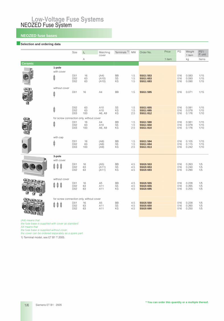
(A4) means that the fuse base is supplied with cover as standard. A4 means that the fuse base is supplied without cover, the cover can be ordered separately as a spare part.
1) Terminal model, see ET B1 T 2005.
Size In Matching Terminals 1) MW Order No. Price PG Weight PS*/P. unitcover 1 item
A 1 item kg Items
Ceramic1-pole
with cover
D01 16 (A4) BB 1.5 5SG1 553 016 0.083 1/15D02 63 (A10) SS 1.5 5SG1 653 016 0.093 1/15D02 63 (A10) KS 1.5 5SG1 693 016 0.090 1/15
without cover
D01 16 A4 BB 1.5 5SG1 595 016 0.071 1/15
D02 63 A10 SS 1.5 5SG1 655 016 0.081 1/15D02 63 A10 KS 1.5 5SG1 695 016 0.078 1/15D03 100 A6, A9 KS 2.5 5SG1 812 016 0.176 1/10
for screw connection only, without cover
D01 16 A4 BB 1.5 5SG1 590 016 0.061 1/15D02 63 A10 SS 1.5 5SG1 650 016 0.078 1/15D03 100 A6, A9 KS 2.5 5SG1 810 016 0.176 1/10
with cap
D01 16 (A8) BB 1.5 5SG1 594 016 0.105 1/15D02 63 (A8) SS 1.5 5SG1 694 016 0.115 1/15D03 100 (A9) KS 2.5 5SG1 813 016 0.242 1/10
3-pole
with cover
D01 16 (A5) BB 4.5 5SG5 553 016 0.263 1/5D02 63 (A11) SS 4.5 5SG5 653 016 0.240 1/5D02 63 (A11) KS 4.5 5SG5 693 016 0.290 1/5
without cover
D01 16 A5 BB 4.5 5SG5 555 016 0.228 1/5D02 63 A11 SS 4.5 5SG5 655 016 0.265 1/5D02 63 A11 KS 4.5 5SG5 695 016 0.255 1/5
for screw connection only, without cover
D01 16 A5 BB 4.5 5SG5 550 016 0.228 1/5D02 63 A11 SS 4.5 5SG5 650 016 0.260 1/5D02 63 A11 KS 4.5 5SG5 690 016 0.250 1/5
* You can order this quantity or a multiple thereof.

NEOZED fuse bases
1/7
NEOZED Fuse SystemLow-Voltage Fuse Systems 1
345678910
1213
Siemens ET B1 · 2005
■ Accessories
MW Order No. Price PG Weight PS*/P. unitP.unit
1 item
1 item kg Items
NEOZED covers made of molded plastic
Cover A1 (for sizes D01, D02), clip-on 1.5 5SH5 244 016 0.008 1/15
Cover A2 (for sizes D01, D02), clip-on 4.5 5SH5 245 016 0.017 1/5
Cover A4 (for size D01), clip-on 1.5 5SH5 251 016 0.012 1/15Cover A10 (for size D02), clip-on 1.5 5SH5 253 016 0.020 1/15
Cover A5 (for size D01), clip-on 4.5 5SH5 252 016 0.035 1/5Cover A11 (for size D02), clip-on 4.5 5SH5 254 016 0.045 1/5
Cover A6 (for size D03), screw-on 2.5 5SH5 233 016 0.021 1/20
NEOZED caps made of molded plastic
Cover A8, clip-on – 5SH5 235 016 0.034 1/20Cover A9, screw-on – 5SH5 234 016 0.066 1/10
* You can order this quantity or a multiple thereof.
NEOZED fuse bases
1/8
NEOZED Fuse SystemLow-Voltage Fuse Systems
Siemens ET B1 · 2005
■ Accessories
1) Terminal model, see ET B1 T 2005.
Size Length Conductor Load capacityup to
for MW Order No. Price
1 item
PG Weight
1 item
PS*/ P. unitapprox. cross-sec-
tionTerminals1)
mm mm2 A kg Items
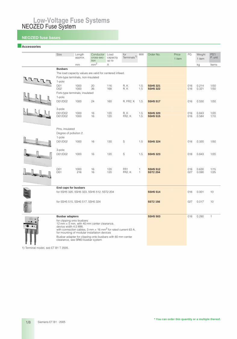
Busbars
The load capacity values are valid for centered infeed.
Fork-type terminals, non-insulated
1-pole
D01 1000 20 116 R, K 1.5 5SH5 321 016 0.214 1/50D02 1000 36 168 R, K 1.5 5SH5 322 016 0.321 1/50
Fork-type terminals, insulated
1-pole
D01/D02 1000 24 160 R, FR2, K 1.5 5SH5 517 016 0.550 1/50
3-pole
D01/D02 1000 16 120 R, K 1.5 5SH5 320 016 0.843 1/20D01/D02 1000 16 120 FR2, K 1.5 5SH5 515 016 0.584 1/10
Pins, insulated
Degree of pollution 2
1-pole
D01/D02 1000 16 130 S 1.5 5SH5 324 016 0.320 1/50
3-pole
D01/D02 1000 16 120 S 1.5 5SH5 323 016 0.843 1/20
D01 1000 16 120 FR1 1 5SH5 512 016 0.630 1/15D01 216 16 120 FR2, K 1 5ST2 204 027 0.090 1/25
End caps for busbars
for 5SH5 320, 5SH5 323, 5SH5 512, 5ST2 204 5SH5 514 016 0.001 10
for 5SH5 515, 5SH5 517, 5SH5 324 5ST2 156 027 0.017 10
Busbar adapters
for clipping onto busbars12 mm × 5 mm, with 40 mm center clearance, device width 4.5 MW, with connection cables, 3 mm × 16 mm2 for rated current 63 A, for mounting of modular installation devices
Busbar adapter for clipping onto busbars with 60 mm center clearance, see SR60 busbar system
5SH5 503 016 0.280 1
* You can order this quantity or a multiple thereof.

NEOZED fuse bases
1/9
NEOZED Fuse SystemLow-Voltage Fuse Systems 1
345678910
1213
Siemens ET B1 · 2005
■ Accessories
Version/Size Order No. Price PG Weight PS*/P. unit1 item
1 item kg Items
Busbar terminals
non-insulated, pin-typefor conductors from 6 mm2 ... 35 mm2 5ST2 203 027 0.001 1/20
insulated, for clipping onto fork-type or pin-typefor conductors from 6 mm2 ... 35 mm2
not suitable for 55 mm mounting depth 5ST2 157 027 0.030 1
insulated, fork-typefor conductors from 6 mm2 ... 25 mm2 5SH5 328 016 0.014 10
insulated, pin-typefor conductors from 2 mm2 ... 25 mm2 5SH5 327 016 0.014 10
non-insulated, pin-typefor two conductors, each from 2 mm2 ... 16 mm2 5SH5 326 016 0.016 1/10
NEOZED screw caps
molded plastic, with inspection hole
D01 5SH4 116 016 0.007 10D02 5SH4 163 016 0.008 10
ceramic
D01, sealable 5SH4 316 016 0.014 10D02, sealable 5SH4 363 016 0.015 10D03 5SH4 100 016 0.070 3
ceramic, with inspection hole
D01 5SH4 317 016 0.014 10D02 5SH4 362 016 0.017 10
* You can order this quantity or a multiple thereof.
NEOZED fuse bases
1/10
NEOZED Fuse SystemLow-Voltage Fuse Systems
Siemens ET B1 · 2005
■ Accessories
Size for Identification color
Order No. Price PG Weight PS*/P. unitfuse 1 item
up to A 1 item kg Items
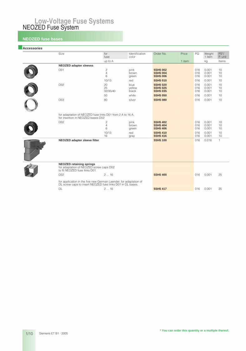
NEOZED adapter sleeves
D01 2 pink 5SH5 002 016 0.001 104 brown 5SH5 004 016 0.001 106 green 5SH5 006 016 0.001 10
10/13 red 5SH5 010 016 0.001 10
D02 20 blue 5SH5 020 016 0.001 1025 yellow 5SH5 025 016 0.001 1032/35/40 black 5SH5 035 016 0.001 10
50 white 5SH5 050 016 0.001 10
D03 80 silver 5SH5 080 016 0.001 10
for adaptation of NEOZED fuse links D01 from 2 A to 16 A, for insertion in NEOZED bases D02
D02 2 pink 5SH5 402 016 0.001 104 brown 5SH5 404 016 0.001 106 green 5SH5 406 016 0.001 10
10/13 red 5SH5 410 016 0.001 1016 gray 5SH5 416 016 0.001 10
NEOZED adapter sleeve fitter 5SH5 100 016 0.016 1
NEOZED retaining springsfor adaptation of NEOZED screw caps D02 to fit NEOZED fuse links D01
D02 2 ... 16 5SH5 400 016 0.001 25
for application in the five new German Laender, for adaptation of DL screw caps to insert NEOZED fuse links D01 in DL bases.
DL 2 ... 16 5SH5 417 016 0.001 25
* You can order this quantity or a multiple thereof.

NEOZED fuse disconnectors
1/11
NEOZED Fuse SystemLow-Voltage Fuse Systems 1
345678910
1213
Siemens ET B1 · 2005
■ Selection and ordering data
No. of poles In Terminals MW Order No. Price PG Weight PS*/P. unit1 item
A 1 item kg Items
D01, draw-out type1 16 FR1 1 5SG7 610 016 0.070 1
1 + N 16 FR1 2 5SG7 650 016 0.150 1
2 16 FR1 2 5SG7 620 016 0.150 1
3 16 FR1 3 5SG7 630 016 0.220 1
3 + N 16 FR1 4 5SG7 660 016 0.300 1
�
�
�
�
�
�
�
�
�
�
�
�
�
�
�
�
�
�
�
�
�
�
�
�
* You can order this quantity or a multiple thereof.

MINIZED switch disconnectors
1/12
NEOZED Fuse SystemLow-Voltage Fuse Systems
Siemens ET B1 · 2005
■ Selection and ordering data
No. of poles In Terminals MW Order No. Price PG Weight PS*/P. unit1 item
A 1 item kg Items
D01, draw-out type, mounting depth 55 mm1 16 FR1 1 5SG7 713 016 0.080 1/3
Version for Italy (no approvals)25 5SG7 713-1B 016 0.080 1/3
1 + N 16 FR1 2 5SG7 753 016 0.150 1/2
Version for Italy (no approvals)25 5SG7 753-1B 016 0.150 1/2
2 16 FR1 2 5SG7 723 016 0.160 1/2
Version for Italy (no approvals)25 5SG7 723-1B 016 0.160 1/2
3 16 FR1 3 5SG7 733 016 0.254 1
Version for Italy (no approvals)25 5SG7 733-1B 016 0.254 1
3 + N 16 FR1 4 5SG7 763 016 0.310 1
Version for Italy (no approvals)25 5SG7 763-1B 016 0.310 1
D02, draw-out type, mounting depth 70 mm1 63 FR2 1.5 5SG7 112 016 0.132 1
1 + N 63 FR2 3 5SG7 152 016 0.265 1
2 63 FR2 3 5SG7 122 016 0.226 1
3 63 FR2 4.5 5SG7 132 016 0.410 1
Versions for Austria (KELAG) only
3 25 5SG7 132-8BA25 016 0.410 1
35 5SG7 132-8BA35 016 0.410 1
50 5SG7 132-8BA50 016 0.410 1
3 + N 63 FR2 6 5SG7 162 016 0.520 1
2
1
1
N
N
2
1 3
2 4
2 4 6
1 3 5
2 4 6 N
1 3 5 N
�
�
�
�
�
�
�
�
�
�
�
�
�
�
�
�
�
�
�
�
�
�
�
�
* You can order this quantity or a multiple thereof.
MINIZED switch disconnectors
1/13
NEOZED Fuse SystemLow-Voltage Fuse Systems 1
345678910
1213
Siemens ET B1 · 2005
■ Accessories
Size for Identification color
Order No. Price PG Weight PS*/P. unitfuse 1 item
up to A 1 item kg Items
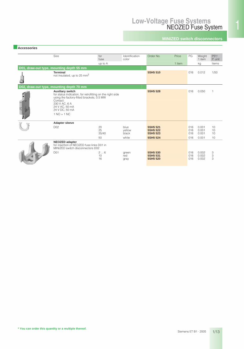
D01, draw-out type, mounting depth 55 mmTerminalnot insulated, up to 25 mm2
5SH5 510 016 0.012 1/50
D02, draw-out type, mounting depth 70 mmAuxiliary switchfor status indication, for retrofitting on the right side using the factory-fitted brackets, 0.5 MW
5SH5 528 016 0.050 1
Contact: 230 V AC, 6 A24 V AC, 50 mA24 V DC, 50 mA
1 NO + 1 NC
Adapter sleeve
D02 20 blue 5SH5 521 016 0.001 1025 yellow 5SH5 522 016 0.001 1035/40 black 5SH5 523 016 0.001 10
50 white 5SH5 524 016 0.001 10
NEOZED adapterfor insertion of NEOZED fuse links D01 in MINIZED switch disconnectors D02
D01 2 ... 6 green 5SH5 530 016 0.002 310 red 5SH5 531 016 0.002 316 gray 5SH5 520 016 0.002 3
* You can order this quantity or a multiple thereof.
DIAZED fuse links
1/14
DIAZED Fuse SystemLow-Voltage Fuse Systems
Siemens ET B1 · 2005
■ Selection and ordering data
1) Rated voltage 500 V AC/400 V DC
Size In Identification color
Thread Order No. Price PG Weight PS*/P. unit1 item
A 1 item kg Items
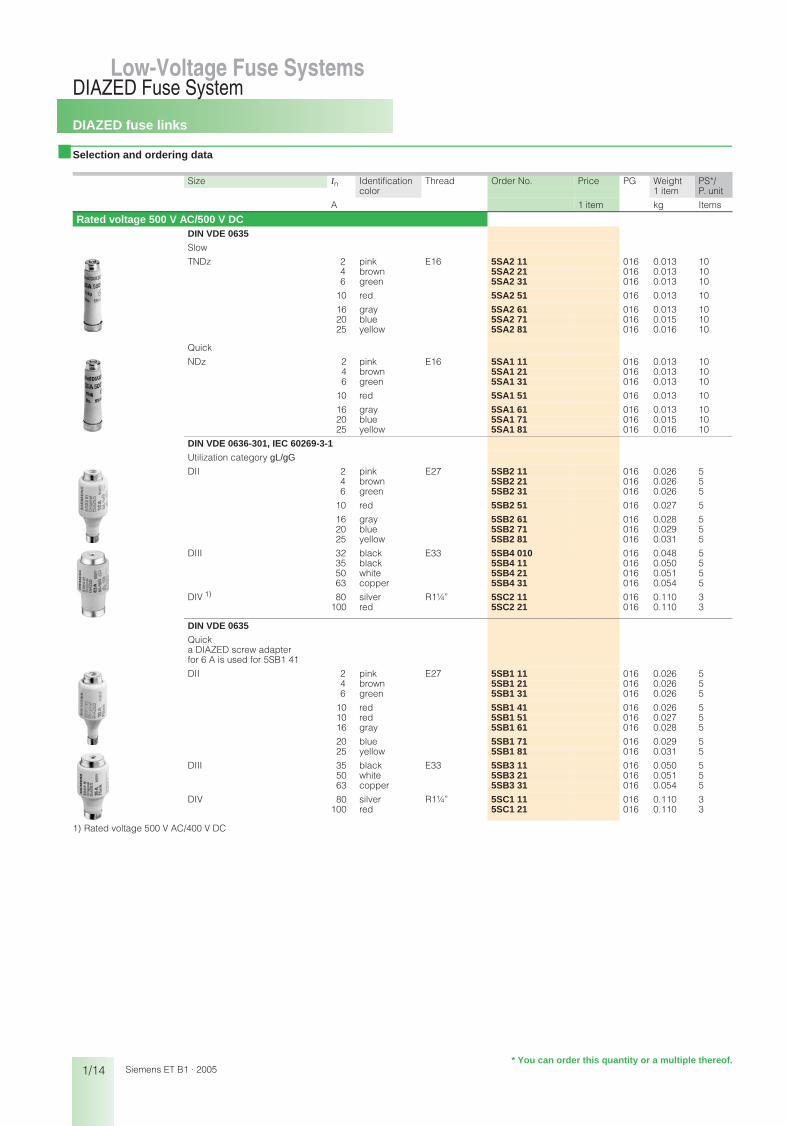
Rated voltage 500 V AC/500 V DCDIN VDE 0635
Slow
TNDz 2 pink E16 5SA2 11 016 0.013 104 brown 5SA2 21 016 0.013 106 green 5SA2 31 016 0.013 10
10 red 5SA2 51 016 0.013 10
16 gray 5SA2 61 016 0.013 1020 blue 5SA2 71 016 0.015 1025 yellow 5SA2 81 016 0.016 10
Quick
NDz 2 pink E16 5SA1 11 016 0.013 104 brown 5SA1 21 016 0.013 106 green 5SA1 31 016 0.013 10
10 red 5SA1 51 016 0.013 10
16 gray 5SA1 61 016 0.013 1020 blue 5SA1 71 016 0.015 1025 yellow 5SA1 81 016 0.016 10
DIN VDE 0636-301, IEC 60269-3-1
Utilization category gL/gG
DII 2 pink E27 5SB2 11 016 0.026 54 brown 5SB2 21 016 0.026 56 green 5SB2 31 016 0.026 5
10 red 5SB2 51 016 0.027 5
16 gray 5SB2 61 016 0.028 520 blue 5SB2 71 016 0.029 525 yellow 5SB2 81 016 0.031 5
DIII 32 black E33 5SB4 010 016 0.048 535 black 5SB4 11 016 0.050 550 white 5SB4 21 016 0.051 563 copper 5SB4 31 016 0.054 5
DIV 1) 80 silver R1¼” 5SC2 11 016 0.110 3100 red 5SC2 21 016 0.110 3
DIN VDE 0635
Quicka DIAZED screw adapter for 6 A is used for 5SB1 41
DII 2 pink E27 5SB1 11 016 0.026 54 brown 5SB1 21 016 0.026 56 green 5SB1 31 016 0.026 5
10 red 5SB1 41 016 0.026 510 red 5SB1 51 016 0.027 516 gray 5SB1 61 016 0.028 5
20 blue 5SB1 71 016 0.029 525 yellow 5SB1 81 016 0.031 5
DIII 35 black E33 5SB3 11 016 0.050 550 white 5SB3 21 016 0.051 563 copper 5SB3 31 016 0.054 5
DIV 80 silver R1¼” 5SC1 11 016 0.110 3100 red 5SC1 21 016 0.110 3
Low-Voltage Fuse Systems
* You can order this quantity or a multiple thereof.
bet_01_02.fm Seite 14 Mittwoch, 16. Februar 2005 9:28 09

DIAZED fuse-links
1/15
DIAZED Fuse SystemLow-Voltage Fuse Systems 1
345678910
1213
Siemens ET B1 · 2005
■ Selection and ordering data
■ Selection and ordering data
Size In Identification color
Thread Order No. Price PG Weight PS*/P. unit1 item
A 1 item kg Items
Rated voltage 690 V AC/600 V DCDIN VDE 0636-301, IEC 60269-3-1
Utilization category gL/gG,DIAZED screw adapters DII are used for fuse links 2 A ... 25 A
DIII 2 pink E33 5SD8 002 016 0.068 54 brown 5SD8 004 016 0.068 56 green 5SD8 006 016 0.068 5
10 red 5SD8 010 016 0.068 516 gray 5SD8 016 016 0.069 5
20 blue 5SD8 020 016 0.071 525 yellow 5SD8 025 016 0.072 5
35 black 5SD8 035 016 0.078 550 white 5SD8 050 016 0.080 563 copper 5SD8 063 016 0.082 5
Rated voltage 750 V AC/750 V DCDIN VDE 0635
for direct current railway facilities,quickDIAZED screw adapters DII are used for fuse links 2 A ... 25 A
DIII 2 pink E33 5SD6 01 016 0.068 54 brown 5SD6 02 016 0.068 56 green 5SD6 03 016 0.068 5
10 red 5SD6 04 016 0.068 516 gray 5SD6 05 016 0.069 5
20 blue 5SD6 06 016 0.071 525 yellow 5SD6 07 016 0.072 535 black 5SD6 08 016 0.078 550 white 5SD6 10 016 0.080 5
63 copper 5SD6 11 016 0.082 5
DIAZED fuse links SILIZED(utilization category gR)
Size In Identification color
Thread Order No. Price PG Weight PS*/P. unit1 item
A 1 item kg Items
Rated voltage 500 V AC/500 V DC DIN VDE 0636-301
for semiconductor protection, designation, yellow ringutilization category gR, super-quickDIAZED screw adapter DII for 25 A is used for the 30 A fuse links
DII 16 gray E27 5SD4 20 016 0.028 520 blue 5SD4 30 016 0.029 525 yellow 5SD4 40 016 0.031 5
30 5SD4 80 016 0.031 5
DIII 35 black E33 5SD4 50 016 0.050 550 white 5SD4 60 016 0.051 563 copper 5SD4 70 016 0.054 5
DIV 80 silver R1¼” 5SD5 10 016 0.110 3100 red 5SD5 20 016 0.110 3
* You can order this quantity or a multiple thereof.
bet_01_02.fm Seite 15 Mittwoch, 16. Februar 2005 9:28 09
DIAZED fuse bases
1/16
DIAZED Fuse SystemLow-Voltage Fuse Systems
Siemens ET B1 · 2005
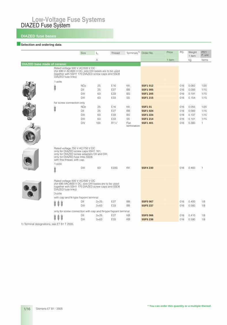
■ Selection and ordering data
1) Terminal designations, see ET B1 T 2005.
Size In Thread Terminals1) Order No. Price PG Weight PS*/P. unit1 item
A 1 item kg Items
DIAZED base made of ceramicRated voltage 500 V AC/500 V DC(for 690 V AC/600 V DC, size DIII bases are to be used together with 5SH1 170 DIAZED screw caps and 5SD8 DIAZED fuse links)
1-pole
NDz 25 E16 KK 5SF1 012 016 0.060 1/20
DII 25 E27 BB 5SF1 005 016 0.093 1/15
DIII 63 E33 BS 5SF1 205 016 0.191 1/15
DIII 63 E33 SS 5SF1 215 016 0.154 1/15
for screw connection only
NDz 25 E16 KK 5SF1 01 016 0.055 1/20
DII 25 E27 BB 5SF1 024 016 0.093 1/15
DIII 63 E33 BS 5SF1 224 016 0.137 1/15
DIII 63 E33 SS 5SF1 214 016 0.141 1/15
DIV 100 R1¼” Flat termination
5SF1 401 016 0.380 1
Rated voltage 750 V AC/750 V DConly for DIAZED screw caps 5SH1 161,only for DIAZED screw adapters DII and DIII,only for DIAZED fuse links 5SD6 with fine thread, with cap.
1-pole
DIII 63 E33S KK 5SF4 230 016 0.460 1
Rated voltage 500 V AC/500 V DC(for 690 VAC/600 V DC, size DIII bases are to be used together with 5SH1 170 DIAZED screw caps and 5SD8 DIAZED fuse links)
3-pole
with cap and N-type fixpoint terminal
DII 3×25 E27 BB 5SF5 067 016 0.400 1/8
DIII 3×63 E33 BB 5SF5 237 016 0.580 1/8
only for screw connection with cap and N-type fixpoint terminal
DII 3×25 E27 KB 5SF5 066 016 0.410 1/8
DIII 3×63 E33 KB 5SF5 236 016 0.590 1/8
* You can order this quantity or a multiple thereof.
bet_01_02.fm Seite 16 Mittwoch, 16. Februar 2005 9:28 09

DIAZED fuse bases
1/17
DIAZED Fuse SystemLow-Voltage Fuse Systems 1
345678910
1213
Siemens ET B1 · 2005
■ Selection and ordering data
1) Terminal designations, see ET B1 T 2005.
Size In Thread Terminals 1) Order No. Price PG Weight PS*/P. unit1 item
A 1 item kg Items
DIAZED base made of molded plasticRated voltage 500 V AC/500 V DCfor mounting rail or screw connectionanti-slip terminal at ingoing and outgoing feedercasing: Silicone-free
Halogen-freeHeat-resistant to 150 °CCreep resistance CTI 225Self-extinguishing according to UL 94
1-pole DII 25 E27 RR 5SF1 060 016 0.152 1/9
DIII 63 E33 RR 5SF1 260 016 0.186 1/9
3-pole DII 3×25 E27 RR 5SF5 068 016 0.457 1/3
DIII 3×63 E33 RR 5SF5 268 016 0.538 1/3
DIAZED bus-mounting base, EZRfor clipping onto 5SH3 5 power rail only for screw connection
1-pole
DII 25 E27 B 5SF6 005 016 0.072 1/15DIII 63 E33 B 5SF6 205 016 0.135 1/15
3-pole
DII 3×25 E27 B 5SF2 07 016 0.351 1/5
* You can order this quantity or a multiple thereof.
bet_01_02.fm Seite 17 Mittwoch, 16. Februar 2005 9:28 09

DIAZED fuse bases
1/18
DIAZED Fuse SystemLow-Voltage Fuse Systems
Siemens ET B1 · 2005
■ Accessories
Size Thread Order No. Price PG Weight PS*/P. unit1 item
1 item kg Items
Mounting partsDIAZED busbar with oblong holesapprox. 1000 mm long
Cross-section: 12 mm × 2 mm, load capacity up to 80 Afor DII, sufficient for 25 bases 5SH3 500 016 0.095 25
Cross-section: 13 mm × 3 mm, load capacity up to 120 Afor DIII, sufficient for 19 bases 5SH3 501 016 0.180 25
Terminals, non-insulatedPin-type, for two conductors from 2 ×1.5 mm2 up to 16 mm2 5SH5 326 016 0.016 1/10
Fork-type, for conductors up to 35 mm2 5SH3 502 016 0.010 25
Busbar for DIAZED EZR bus-mounting basesuitable for fork-type terminal connection, ready-made drilling with thread for screw adapters, approx. 2000 mm longcross-section 16 mm x 3 mm, load capacity up to 150 A for lateral incoming supply
for DII sufficient for 42 5SF6 005 bases 5SH3 54 016 0.740 1/5for DII and DIII sufficient for 34 5SF6 205 bases 5SH3 55 016 0.740 1/5for DII sufficient for 27 5SF2 07 bases 5SH3 56 016 0.740 1/5
EZR bus-mounting terminalnon-insulated
for conductors up to 16 mm2 8JH4 122 113 0.012 1for conductors up to 35 mm2 8JH4 124 113 0.024 1
DIAZED coversDIAZED cover molded plasticnot for SILIZED fuse links
1-pole
(5 DIAZED bases = 12 MW)DII E27 5SH2 032 016 0.017 1/20
(4 DIAZED bases = 12 MW)DIII E33 5SH2 232 016 0.020 1/20
Capmolded plastic1-pole
NDz E16 5SH2 01 016 0.028 1/10DII E27 5SH2 02 016 0.038 1/20DIII E33 5SH2 22 016 0.048 1/20
DIV R1¼” 5SH2 40 016 0.115 1/5
Cover ring1-pole
molded plasticalso for bus-mounting base EZRDII E27 5SH3 401 016 0.013 5DIII E33 5SH3 411 016 0.014 5
ceramicDII and DIII also for bus-mounting base EZRNDz E16 5SH3 30 016 0.020 1/100DII E27 5SH3 32 016 0.029 10DIII E33 5SH3 34 016 0.035 10
* You can order this quantity or a multiple thereof.
bet_01_02.fm Seite 18 Mittwoch, 16. Februar 2005 9:28 09

DIAZED fuse bases
1/19
DIAZED Fuse SystemLow-Voltage Fuse Systems 1
345678910
1213
Siemens ET B1 · 2005
■ Accessories
1) Suitable for a rated voltage of up to 750 V.
Size Thread for fuse Order No. Price PG Weight PS*/P. unitlinks 1 item
A 1 item kg Items
Screw adapters, adapter sleevesDIAZED screw adapters
NDz E16 2 5SH3 28 016 0.002 104 5SH3 31 016 0.002 106 5SH3 05 016 0.002 10
10 5SH3 06 016 0.002 1016 5SH3 07 016 0.002 10
also for mounting in DIAZED base DIII
DII 1) E27 2 5SH3 10 016 0.015 104 5SH3 11 016 0.015 106 5SH3 12 016 0.015 10
10 5SH3 13 016 0.015 1016 5SH3 14 016 0.014 1020 5SH3 15 016 0.012 10
25 5SH3 16 016 0.012 10
DIII 1) E33 35 5SH3 17 016 0.019 1050 5SH3 18 016 0.018 1063 5SH3 20 016 0.017 10
DIAZED adapter sleevefor DIV bases
DIV R1¼” 80 5SH3 21 016 0.006 10100 5SH3 22 016 0.005 10
DIAZED adapter sleevesfor snapping into DIAZED screw caps,if DIAZED fuse links E16are inserted in DIAZED bases DII 5SH3 01 016 0.012 10
if DIAZED fuse links DIIare inserted in DIAZED bases DIII 5SH3 02 016 0.023 10
DIAZED adapter sleeve fitter for DII/DIII 5SH3 703 016 0.025 1
* You can order this quantity or a multiple thereof.
bet_01_02.fm Seite 19 Mittwoch, 16. Februar 2005 9:28 09

DIAZED fuse bases
1/20
DIAZED Fuse SystemLow-Voltage Fuse Systems
Siemens ET B1 · 2005
■ Accessories
Size In Thread Order No. Price PG Weight PS*/P. unit1 item
A 1 item kg Items
DIAZED screw capsRated voltage 500 V AC/500 V DC
ceramic
NDz 25 E16 5SH1 11 016 0.016 5
molded plastic, with inspection hole, black, not for SILIZED fuse links
DII 25 E27 5SH1 221 016 0.026 5
DIII 63 E33 5SH1 231 016 0.042 5
narrow version, ceramic
DII 25 E27 5SH1 12 016 0.034 5
DIII 63 E33 5SH1 13 016 0.059 5
mushroom shape, ceramic, with inspection hole, sealable
DII 25 E27 5SH1 22 016 0.050 5
DIII 63 E33 5SH1 23 016 0.080 5
ceramic
DIV 100 R1¼” 5SH1 141 016 0.181 1
Rated voltage 750 V AC/750 V DC
only for 5SD6 DIAZED fuse linksand 5SF4 230 DIAZED fuse basesceramic, with fine thread
DIII 63 E33S 5SH1 161 016 0.084 1
Rated voltage 690 V AC/600 V DC
only for 5SD8 DIAZED fuse linksceramic, prolonged version
DIII 63 E33 5SH1 170 016 0.086 1
* You can order this quantity or a multiple thereof.
bet_01_02.fm Seite 20 Mittwoch, 16. Februar 2005 9:28 09

LV HRC fuse links
1/21
LV HRC Fuse SystemLow-Voltage Fuse Systems 1
345678910
1213
Siemens ET B1 · 2005
Low-Voltage Fuse Systems
■ Selection and ordering data
Size Width In Un Insulated PG Weight PS*/P. unitgrip lugs 1 item
Order No. Price
mm A V 1 item kg Items
LV HRC fuse links with combination alarm, utilization category gL/gGLV HRC fuse links of size 000 can also be used in LV HRC fuse bases, LV HRC fuse switch disconnectors, LV HRC fuse strips as well as inLV HRC in-line fuse switch disconnectors of size 00.
000 21 10 400 V AC 3NA6 803-4 013 0.135 316 3NA6 805-4 013 0.135 320 3NA6 807-4 013 0.135 3
25 3NA6 810-4 013 0.135 332 3NA6 812-4 013 0.135 335 3NA6 814-4 013 0.135 3
40 3NA6 817-4 013 0.135 350 3NA6 820-4 013 0.135 363 3NA6 822-4 013 0.135 3
80 3NA6 824-4 013 0.135 3100 3NA6 830-4 013 0.135 3
00 30 80 400 V AC 3NA6 824-4KK 013 0.200 3100 3NA6 830-4KK 013 0.200 3125 3NA6 832-4 013 0.200 3
160 3NA6 836-4 013 0.200 3
1 30 35 400 V AC 3NA6 114-4 013 0.290 340 3NA6 117-4 013 0.290 350 3NA6 120-4 013 0.290 3
63 3NA6 122-4 013 0.290 380 3NA6 124-4 013 0.290 3
100 3NA6 130-4 013 0.290 3
125 3NA6 132-4 013 0.290 3160 3NA6 136-4 013 0.290 3
47.2 200 3NA6 140-4 013 0.430 3224 3NA6 142-4 013 0.430 3250 3NA6 144-4 013 0.430 3
2 47.2 50 400 V AC 3NA6 220-4 013 0.450 363 3NA6 222-4 013 0.450 380 3NA6 224-4 013 0.450 3
100 3NA6 230-4 013 0.450 3125 3NA6 232-4 013 0.450 3160 3NA6 236-4 013 0.450 3
200 3NA6 240-4 013 0.450 3224 3NA6 242-4 013 0.450 3
250 3NA6 244-4 013 0.450 3300 3NA6 250-4 013 0.650 3
57.8 315 3NA6 252-4 013 0.650 3355 3NA6 254-4 013 0.650 3400 3NA6 260-4 013 0.650 3
* You can order this quantity or a multiple thereof.
bet_01_03.fm Seite 21 Mittwoch, 16. Februar 2005 9:29 09

LV HRC fuse links
1/22
LV HRC Fuse SystemLow-Voltage Fuse Systems
Siemens ET B1 · 2005
■ Selection and ordering data
Size Width In Un Non-insulated Insulated PG Weight PS*/P. unitgrip lugs grip lugs 1 item
Order No. Price Order No. Price
mm A V 1 item 1 item kg Items
LV HRC fuse links with combination alarm, utilization category gG
LV HRC fuse links of size 000 can also be used in LV HRC fuse bases, LV HRC fuse switch disconnectors, LV HRC fuse strips as well as inLV HRC in-line fuse switch disconnectors of size 00.
The 300 A and 355 A fuse links do not conform to a VDE mark. They correspond to the standard, but are not permissible.
000 21 2 500 V AC/ 250 V DC
3NA7 802 3NA6 802 013 0.135 34 3NA7 804 3NA6 804 013 0.135 36 3NA7 801 3NA6 801 013 0.135 3
10 3NA7 803 3NA6 803 013 0.136 316 3NA7 805 3NA6 805 013 0.136 320 3NA7 807 3NA6 807 013 0.136 3
25 3NA7 810 3NA6 810 013 0.136 332 3NA7 812 3NA6 812 013 0.136 335 3NA7 814 3NA6 814 013 0.136 3
40 3NA7 817 3NA6 817 013 0.136 350 3NA7 820 3NA6 820 013 0.136 363 3NA7 822 3NA6 822 013 0.136 3
80 3NA7 824 3NA6 824 013 0.136 3100 3NA7 830 3NA6 830 013 0.136 3
00 30 80 500 V AC/ 250 V DC
3NA7 824-7 3NA6 824-7 013 0.211 3100 3NA7 830-7 3NA6 830-7 013 0.211 3125 3NA7 832 3NA6 832 013 0.211 3
160 3NA7 836 3NA6 836 013 0.211 3
1 30 16 500 V AC/ 440 V DC
3NA7 105 3NA6 105 013 0.290 320 3NA7 107 3NA6 107 013 0.290 325 3NA7 110 3NA6 110 013 0.290 3
35 3NA7 114 3NA6 114 013 0.290 340 3NA7 117 3NA6 117 013 0.290 350 3NA7 120 3NA6 120 013 0.290 3
63 3NA7 122 3NA6 122 013 0.290 380 3NA7 124 3NA6 124 013 0.290 3
100 3NA7 130 3NA6 130 013 0.290 3
125 3NA7 132 3NA6 132 013 0.290 3160 3NA7 136 3NA6 136 013 0.290 3
47.2 200 3NA7 140 3NA6 140 013 0.440 3224 3NA7 142 3NA6 142 013 0.440 3250 3NA7 144 3NA6 144 013 0.440 3
2 47.2 35 500 V AC/ 440 V DC
3NA7 214 3NA6 214 013 0.450 350 3NA7 220 3NA6 220 013 0.450 363 3NA7 222 3NA6 222 013 0.450 3
80 3NA7 224 3NA6 224 013 0.450 3100 3NA7 230 3NA6 230 013 0.450 3125 3NA7 232 3NA6 232 013 0.450 3
160 3NA7 236 3NA6 236 013 0.450 3200 3NA7 240 3NA6 240 013 0.450 3
224 3NA7 242 3NA6 242 013 0.450 3250 3NA7 244 3NA6 244 013 0.450 3
57.8 300 – 3NA6 250 013 0.641 3 315 3NA7 252 3NA6 252 013 0.660 3
355 – 3NA6 254 013 0.641 3400 3NA7 260 3NA6 260 013 0.660 3
* You can order this quantity or a multiple thereof.
bet_01_03.fm Seite 22 Mittwoch, 16. Februar 2005 9:29 09

LV HRC fuse links
1/23
LV HRC Fuse SystemLow-Voltage Fuse Systems 1
345678910
1213
Siemens ET B1 · 2005
■ Selection and ordering data
Further versions on request.
Size Width In Un Non-insulated Insulated PG Weight PS*/P. unitgrip lugs grip lugs 1 item
Order No. Price Order No. Price
mm A V 1 item 1 item kg Items
LV HRC fuse links with combination alarmutilization category gG
LV HRC fuse links of size 000 can also be used in LV HRC fuse bases, LV HRC fuse switch disconnectors, LV HRC fuse strips as well as inLV HRC in-line fuse switch disconnectors of size 00.
The 300 A fuse links do not conform to a VDE mark. They correspond to the standard, but are not permissible.
000 21 2 690 V AC/ 250 V DC
3NA7 802-6 3NA6 802-6 013 0.136 34 3NA7 804-6 3NA6 804-6 013 0.136 36 3NA7 801-6 3NA6 801-6 013 0.136 3
10 3NA7 803-6 3NA6 803-6 013 0.136 316 3NA7 805-6 3NA6 805-6 013 0.136 320 3NA7 807-6 3NA6 807-6 013 0.136 3
25 3NA7 810-6 3NA6 810-6 013 0.136 332 3NA7 812-6 3NA6 812-6 013 0.136 335 3NA7 814-6 3NA6 814-6 013 0.136 3
00 30 40 690 V AC/ 250 V DC
3NA7 817-6 3NA6 817-6 013 0.211 350 3NA7 820-6 3NA6 820-6 013 0.211 363 3NA7 822-6 3NA6 822-6 013 0.211 3
80 3NA7 824-6 3NA6 824-6 013 0.211 3100 3NA7 830-6 3NA6 830-6 013 0.211 3
1 30 50 690 V AC/ 440 V DC
3NA7 120-6 3NA6 120-6 013 0.290 363 3NA7 122-6 3NA6 122-6 013 0.290 380 3NA7 124-6 3NA6 124-6 013 0.290 3
100 3NA7 130-6 3NA6 130-6 013 0.290 3125 3NA7 132-6 3NA6 132-6 013 0.290 3160 3NA7 136-6 3NA6 136-6 013 0.290 3
47.2 200 3NA7 140-6 3NA6 140-6 013 0.440 3
2 47.2 80 690 V AC/ 440 V DC
3NA7 224-6 3NA6 224-6 013 0.450 3100 3NA7 230-6 3NA6 230-6 013 0.450 3125 3NA7 232-6 3NA6 232-6 013 0.450 3
160 3NA7 236-6 3NA6 236-6 013 0.450 3200 3NA7 240-6 3NA6 240-6 013 0.450 3
57.8 224 3NA7 242-6 3NA6 242-6 013 0.660 3250 3NA7 244-6 3NA6 244-6 013 0.660 3
300 3NA7 250-6 3NA6 250-6 013 0.660 3315 3NA7 252-6 3NA6 252-6 013 0.660 3
* You can order this quantity or a multiple thereof.
bet_01_03.fm Seite 23 Mittwoch, 16. Februar 2005 9:29 09

LV HRC fuse links
1/24
LV HRC Fuse SystemLow-Voltage Fuse Systems
Siemens ET B1 · 2005
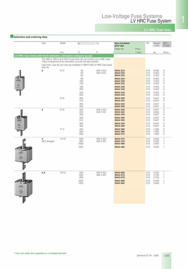
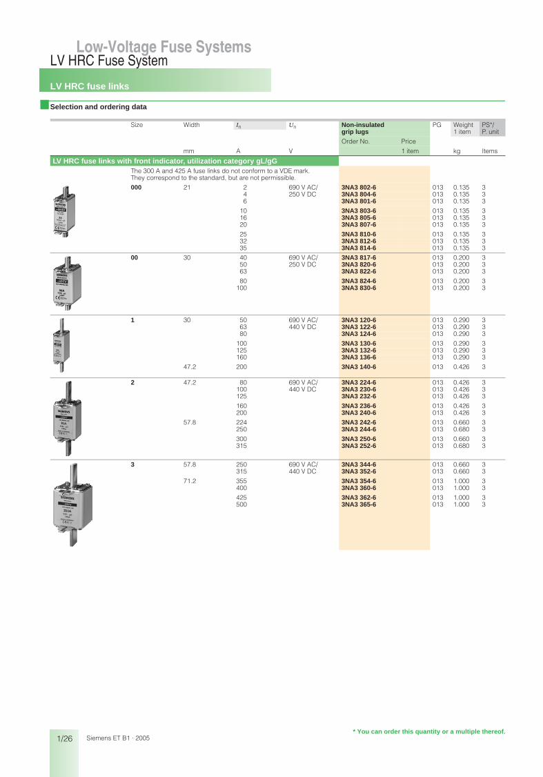
■ Selection and ordering data
Size Width In Un Non-insulated PG Weight PS*/P. unitgrip lugs 1 item
Order No. Price
mm A V 1 item kg Items
LV HRC fuse links with front indicator, utilization category gL/gGLV HRC fuse links of size 000 can also be used in LV HRC fuse bases, LV HRC fuse switch disconnectors, LV HRC fuse strips as well as inLV HRC in-line fuse switch disconnectors of size 00.
000 21 2 500 V AC/ 250 V DC
3NA3 802 013 0.133 34 3NA3 804 013 0.133 36 3NA3 801 013 0.133 3
10 3NA3 803 013 0.133 316 3NA3 805 013 0.133 320 3NA3 807 013 0.133 3
25 3NA3 810 013 0.133 332 3NA3 812 013 0.133 335 3NA3 814 013 0.133 3
40 3NA3 817 013 0.133 350 3NA3 820 013 0.133 363 3NA3 822 013 0.133 3
80 3NA3 824 013 0.133 3100 3NA3 830 013 0.133 3
00 30 35 500 V AC/ 250 V DC
3NA3 814-7 013 0.200 350 3NA3 820-7 013 0.200 363 3NA3 822-7 013 0.200 3
80 3NA3 824-7 013 0.200 3100 3NA3 830-7 013 0.200 3125 3NA3 832 013 0.217 3
160 3NA3 836 013 0.217 3
0 30 6 500 V AC/ 3NA3 001 013 0.340 310 440 V DC 3NA3 003 013 0.340 316 3NA3 005 013 0.340 3
20 3NA3 007 013 0.340 325 3NA3 010 013 0.340 332 3NA3 012 013 0.340 3
35 3NA3 014 013 0.340 340 3NA3 017 013 0.340 350 3NA3 020 013 0.340 3
63 3NA3 022 013 0.340 380 3NA3 024 013 0.340 3
100 3NA3 030 013 0.340 3
125 3NA3 032 013 0.340 3160 3NA3 036 013 0.340 3
1 30 16 500 V AC/ 3NA3 105 013 0.290 320 440 V DC 3NA3 107 013 0.290 325 3NA3 110 013 0.290 3
35 3NA3 114 013 0.300 340 3NA3 117 013 0.300 350 3NA3 120 013 0.300 3
63 3NA3 122 013 0.300 380 3NA3 124 013 0.300 3
100 3NA3 130 013 0.300 3
125 3NA3 132 013 0.300 3160 3NA3 136 013 0.300 3
47.2 200 3NA3 140 013 0.440 3224 3NA3 142 013 0.440 3250 3NA3 144 013 0.440 3
* You can order this quantity or a multiple thereof.
bet_01_03.fm Seite 24 Mittwoch, 16. Februar 2005 9:29 09
LV HRC fuse links
1/25
LV HRC Fuse SystemLow-Voltage Fuse Systems 1
345678910
1213
Siemens ET B1 · 2005
■ Selection and ordering data
Size Width In Un Non-insulated PG Weight PS*/P. unitgrip lugs 1 item
Order No. Price
mm A V 1 item kg Items
LV HRC fuse links with front indicator, utilization category gL/gGThe 300 A, 355 A and 425 A fuse links do not conform to a VDE mark. They correspond to the standard, but are not permissible.
fuse links, size 4a can only be installed in 3NH7 520 LV HRC fuse base, size 4a.
2 47.2 35 500 V AC/ 3NA3 214 013 0.453 350 440 V DC 3NA3 220 013 0.453 363 3NA3 222 013 0.453 3
80 3NA3 224 013 0.453 3100 3NA3 230 013 0.453 3125 3NA3 232 013 0.453 3
160 3NA3 236 013 0.453 3200 3NA3 240 013 0.453 3
224 3NA3 242 013 0.453 3250 3NA3 244 013 0.453 3
57.8 300 3NA3 250 013 0.647 3315 3NA3 252 013 0.647 3
355 3NA3 254 013 0.647 3400 3NA3 260 013 0.647 3
3 57.8 200 500 V AC/ 3NA3 340 013 0.647 3224 440 V DC 3NA3 342 013 0.640 3250 3NA3 344 013 0.647 3
300 3NA3 350 013 0.647 3315 3NA3 352 013 0.647 3
355 3NA3 354 013 0.647 3400 3NA3 360 013 0.647 3
71.2 425 3NA3 362 013 1.000 3500 3NA3 365 013 1.000 3630 3NA3 372 013 1.000 3
4 101.8 630 500 V AC/ 3NA3 472 013 2.500 1(IEC design) 800 440 V DC 3NA3 475 013 2.500 1
1000 3NA3 480 013 2.500 1
1250 3NA3 482 013 2.500 1
4 A 101.8 500 500 V AC/ 3NA3 665 013 2.700 1630 440 V DC 3NA3 672 013 2.700 1800 3NA3 675 013 2.700 1
1000 3NA3 680 013 2.840 11250 3NA3 682 013 2.840 1
* You can order this quantity or a multiple thereof.
bet_01_03.fm Seite 25 Mittwoch, 16. Februar 2005 9:29 09
LV HRC fuse links
1/26
LV HRC Fuse SystemLow-Voltage Fuse Systems
Siemens ET B1 · 2005* You can order this quantity or a multiple thereof.
■ Selection and ordering data
Size Width In Un Non-insulated PG Weight PS*/P. unitgrip lugs 1 item
Order No. Price
mm A V 1 item kg Items
LV HRC fuse links with front indicator, utilization category gL/gGThe 300 A and 425 A fuse links do not conform to a VDE mark. They correspond to the standard, but are not permissible.
000 21 2 690 V AC/ 250 V DC
3NA3 802-6 013 0.135 34 3NA3 804-6 013 0.135 36 3NA3 801-6 013 0.135 3
10 3NA3 803-6 013 0.135 316 3NA3 805-6 013 0.135 320 3NA3 807-6 013 0.135 3
25 3NA3 810-6 013 0.135 332 3NA3 812-6 013 0.135 335 3NA3 814-6 013 0.135 3
00 30 40 690 V AC/ 250 V DC
3NA3 817-6 013 0.200 350 3NA3 820-6 013 0.200 363 3NA3 822-6 013 0.200 3
80 3NA3 824-6 013 0.200 3100 3NA3 830-6 013 0.200 3
1 30 50 690 V AC/ 440 V DC
3NA3 120-6 013 0.290 363 3NA3 122-6 013 0.290 380 3NA3 124-6 013 0.290 3
100 3NA3 130-6 013 0.290 3125 3NA3 132-6 013 0.290 3160 3NA3 136-6 013 0.290 3
47.2 200 3NA3 140-6 013 0.426 3
2 47.2 80 690 V AC/ 440 V DC
3NA3 224-6 013 0.426 3100 3NA3 230-6 013 0.426 3125 3NA3 232-6 013 0.426 3
160 3NA3 236-6 013 0.426 3200 3NA3 240-6 013 0.426 3
57.8 224 3NA3 242-6 013 0.660 3250 3NA3 244-6 013 0.680 3
300 3NA3 250-6 013 0.660 3315 3NA3 252-6 013 0.680 3
3 57.8 250 690 V AC/ 440 V DC
3NA3 344-6 013 0.660 3315 3NA3 352-6 013 0.660 3
71.2 355 3NA3 354-6 013 1.000 3400 3NA3 360-6 013 1.000 3
425 3NA3 362-6 013 1.000 3500 3NA3 365-6 013 1.000 3
bet_01_03.fm Seite 26 Mittwoch, 16. Februar 2005 9:29 09

LV HRC fuse links
1/27
LV HRC Fuse SystemLow-Voltage Fuse Systems 1
345678910
1213
Siemens ET B1 · 2005* You can order this quantity or a multiple thereof.
■ Selection and ordering data
Size Width In Un Non-insulated PG Weight PS*/P. unitgrip lugs 1 item
Order No. Price
mm A V 1 item kg Items
LV HRC fuse links with front indicator, utilization category aM000 21 6 500 V AC 3ND1 801 014 0.130 3
10 3ND1 803 014 0.130 316 3ND1 805 014 0.130 3
20 3ND1 807 014 0.130 325 3ND1 810 014 0.130 332 3ND1 812 014 0.130 3
35 3ND1 814 014 0.130 340 3ND1 817 014 0.130 350 3ND1 820 014 0.130 3
63 3ND1 822 014 0.130 380 3ND1 824 014 0.130 3
00 30 100 500 V AC 3ND1 830 014 0.192 3125 3ND1 832 014 0.192 3160 3ND1 836 014 0.192 3
1 30 63 690 V AC 3ND2 122 014 0.290 380 3ND2 124 014 0.290 3
100 3ND2 130 014 0.440 3
47.2 125 3ND2 132 014 0.440 3160 3ND2 136 014 0.440 3
200 3ND2 140 014 0.440 3250 3ND2 144 014 0.440 3
2 47.2 125 690 V AC 3ND2 232 014 0.440 3160 3ND2 236 014 0.440 3
200 3ND2 240 014 0.440 3250 3ND2 244 014 0.440 3
57.8 315 3ND2 252 014 0.650 3355 3ND2 254 014 0.650 3400 3ND2 260 014 0.650 3
3 57.8 315 690 V AC 3ND2 352 014 0.650 3355 3ND2 354 014 0.650 3400 3ND2 360 014 0.650 3
71.2 500 3ND1 365 014 1.030 3630 3ND1 372 014 1.000 3
bet_01_03.fm Seite 27 Mittwoch, 16. Februar 2005 9:29 09
LV HRC fuse links SITOR
1/28
LV HRC Fuse SystemLow-Voltage Fuse Systems
Siemens ET B1 · 2005
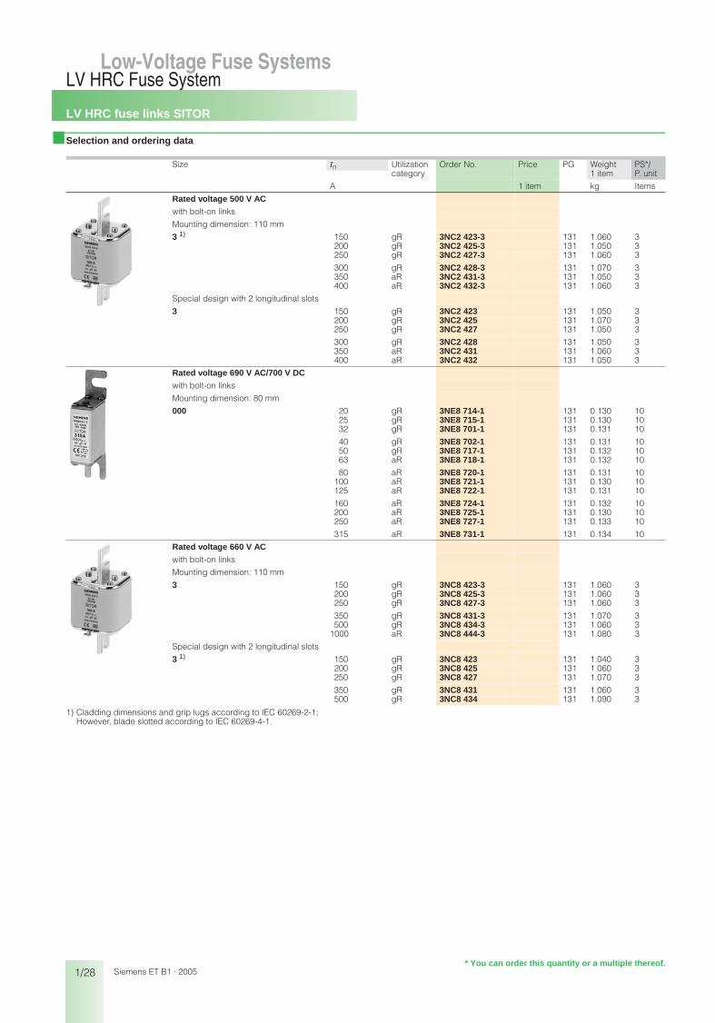
■ Selection and ordering data
1) Cladding dimensions and grip lugs according to IEC 60269-2-1;However, blade slotted according to IEC 60269-4-1.
Size In Utilization Order No. Price PG Weight PS*/P. unitcategory 1 item
A 1 item kg Items
Rated voltage 500 V AC
with bolt-on links
Mounting dimension: 110 mm
3 1) 150 gR 3NC2 423-3 131 1.060 3200 gR 3NC2 425-3 131 1.050 3250 gR 3NC2 427-3 131 1.060 3
300 gR 3NC2 428-3 131 1.070 3350 aR 3NC2 431-3 131 1.050 3400 aR 3NC2 432-3 131 1.060 3
Special design with 2 longitudinal slots
3 150 gR 3NC2 423 131 1.050 3200 gR 3NC2 425 131 1.070 3250 gR 3NC2 427 131 1.050 3
300 gR 3NC2 428 131 1.050 3350 aR 3NC2 431 131 1.060 3400 aR 3NC2 432 131 1.050 3
Rated voltage 690 V AC/700 V DC
with bolt-on links
Mounting dimension: 80 mm
000 20 gR 3NE8 714-1 131 0.130 1025 gR 3NE8 715-1 131 0.130 1032 gR 3NE8 701-1 131 0.131 10
40 gR 3NE8 702-1 131 0.131 1050 gR 3NE8 717-1 131 0.132 1063 aR 3NE8 718-1 131 0.132 10
80 aR 3NE8 720-1 131 0.131 10100 aR 3NE8 721-1 131 0.130 10125 aR 3NE8 722-1 131 0.131 10
160 aR 3NE8 724-1 131 0.132 10200 aR 3NE8 725-1 131 0.130 10250 aR 3NE8 727-1 131 0.133 10
315 aR 3NE8 731-1 131 0.134 10
Rated voltage 660 V AC
with bolt-on links
Mounting dimension: 110 mm
3 150 gR 3NC8 423-3 131 1.060 3200 gR 3NC8 425-3 131 1.060 3250 gR 3NC8 427-3 131 1.060 3
350 gR 3NC8 431-3 131 1.070 3500 gR 3NC8 434-3 131 1.060 3
1000 aR 3NC8 444-3 131 1.080 3
Special design with 2 longitudinal slots
3 1) 150 gR 3NC8 423 131 1.040 3200 gR 3NC8 425 131 1.060 3250 gR 3NC8 427 131 1.070 3
350 gR 3NC8 431 131 1.060 3500 gR 3NC8 434 131 1.090 3
Low-Voltage Fuse Systems
* You can order this quantity or a multiple thereof.
bet_01_04.fm Seite 28 Mittwoch, 16. Februar 2005 9:30 09
LV HRC fuse links SITOR
1/29
LV HRC Fuse SystemLow-Voltage Fuse Systems 1
345678910
1213
Siemens ET B1 · 2005
■ Selection and ordering data
Size In Utilization Order No. Price PG Weight PS*/P. unitcategory 1 item
A 1 item kg Items
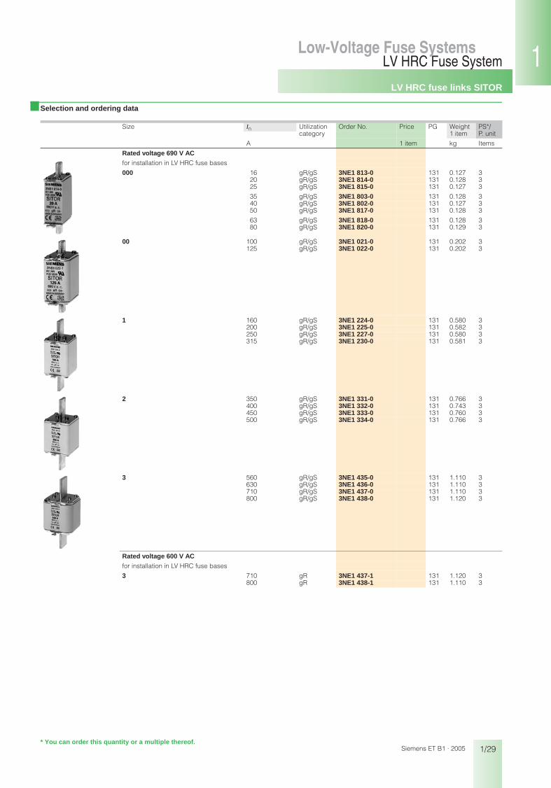
Rated voltage 690 V AC
for installation in LV HRC fuse bases
000 16 gR/gS 3NE1 813-0 131 0.127 320 gR/gS 3NE1 814-0 131 0.128 325 gR/gS 3NE1 815-0 131 0.127 3
35 gR/gS 3NE1 803-0 131 0.128 340 gR/gS 3NE1 802-0 131 0.127 350 gR/gS 3NE1 817-0 131 0.128 3
63 gR/gS 3NE1 818-0 131 0.128 380 gR/gS 3NE1 820-0 131 0.129 3
00 100 gR/gS 3NE1 021-0 131 0.202 3125 gR/gS 3NE1 022-0 131 0.202 3
1 160 gR/gS 3NE1 224-0 131 0.580 3200 gR/gS 3NE1 225-0 131 0.582 3250 gR/gS 3NE1 227-0 131 0.580 3315 gR/gS 3NE1 230-0 131 0.581 3
2 350 gR/gS 3NE1 331-0 131 0.766 3400 gR/gS 3NE1 332-0 131 0.743 3450 gR/gS 3NE1 333-0 131 0.760 3500 gR/gS 3NE1 334-0 131 0.766 3
3 560 gR/gS 3NE1 435-0 131 1.110 3630 gR/gS 3NE1 436-0 131 1.110 3710 gR/gS 3NE1 437-0 131 1.110 3800 gR/gS 3NE1 438-0 131 1.120 3
Rated voltage 600 V AC
for installation in LV HRC fuse bases
3 710 gR 3NE1 437-1 131 1.120 3800 gR 3NE1 438-1 131 1.110 3
* You can order this quantity or a multiple thereof.
bet_01_04.fm Seite 29 Mittwoch, 16. Februar 2005 9:30 09

LV HRC fuse links SITOR
1/30
LV HRC Fuse SystemLow-Voltage Fuse Systems
Siemens ET B1 · 2005
■ Selection and ordering data
1) Cladding dimensions and grip lugs according to IEC 60269-2-1;However, blade slotted according to IEC 60269-4-1.
Size In Utilization Order No. Price PG Weight PS*/P. unitcategory 1 item
A 1 item kg Items
Rated voltage 690 V AC
for installation in LV HRC fuse bases
00 125 gR 3NE1 022-2 131 0.203 3
1 160 gR 3NE1 224-2 131 0.613 3200 gR 3NE1 225-2 131 0.612 3250 gR 3NE1 227-2 131 0.626 3315 gR 3NE1 230-2 131 0.615 3
2 350 gR 3NE1 331-2 131 0.754 3450 gR 3NE1 333-2 131 0.768 3500 gR 3NE1 334-2 131 0.768 3
3 560 gR 3NE1 435-2 131 1.140 3630 gR 3NE1 436-2 131 1.170 3670 gR 3NE1 447-2 131 1.170 3
710 gR 3NE1 437-2 131 1.150 3800 gR 3NE1 438-2 131 1.180 3850 gR 3NE1 448-2 131 1.200 3
00 25 gR 3NE8 015-1 131 0.205 335 gR 3NE8 003-1 131 0.204 350 gR 3NE8 017-1 131 0.203 3
63 gR 3NE8 018-1 131 0.205 380 aR 3NE8 020-1 131 0.203 3
100 aR 3NE8 021-1 131 0.205 3
125 aR 3NE8 022-1 131 0.213 3160 aR 3NE8 024-1 131 0.207 3
Rated voltage 800 V AC
with bolt-on links
Mounting dimension: 110 mm
2 1) 250 aR 3NE4 327-0B 131 0.753 3315 aR 3NE4 330-0B 131 0.760 3450 aR 3NE4 333-0B 131 0.760 3
500 aR 3NE4 334-0B 131 0.754 3710 aR 3NE4 337 131 0.771 3
* You can order this quantity or a multiple thereof.
bet_01_04.fm Seite 30 Mittwoch, 16. Februar 2005 9:30 09
LV HRC fuse links SITOR
1/31
LV HRC Fuse SystemLow-Voltage Fuse Systems 1
345678910
1213
Siemens ET B1 · 2005
■ Selection and ordering data
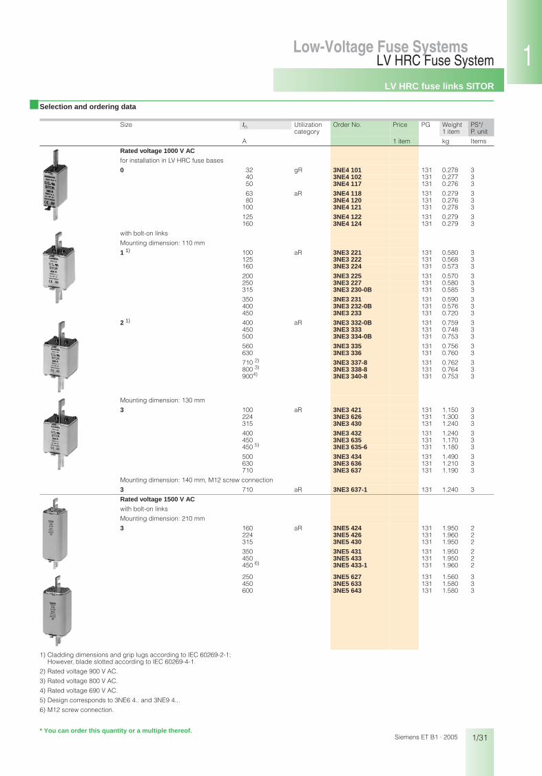
1) Cladding dimensions and grip lugs according to IEC 60269-2-1;However, blade slotted according to IEC 60269-4-1.
2) Rated voltage 900 V AC.
3) Rated voltage 800 V AC.
4) Rated voltage 690 V AC.
5) Design corresponds to 3NE6 4.. and 3NE9 4...
6) M12 screw connection.
Size In Utilization Order No. Price PG Weight PS*/P. unitcategory 1 item
A 1 item kg Items
Rated voltage 1000 V AC
for installation in LV HRC fuse bases
0 32 gR 3NE4 101 131 0.278 340 3NE4 102 131 0.277 350 3NE4 117 131 0.276 3
63 aR 3NE4 118 131 0.279 380 3NE4 120 131 0.276 3
100 3NE4 121 131 0.278 3
125 3NE4 122 131 0.279 3160 3NE4 124 131 0.279 3
with bolt-on links
Mounting dimension: 110 mm
1 1) 100 aR 3NE3 221 131 0.580 3125 3NE3 222 131 0.568 3160 3NE3 224 131 0.573 3
200 3NE3 225 131 0.570 3250 3NE3 227 131 0.580 3315 3NE3 230-0B 131 0.585 3
350 3NE3 231 131 0.590 3400 3NE3 232-0B 131 0.576 3450 3NE3 233 131 0.720 3
2 1) 400 aR 3NE3 332-0B 131 0.759 3450 3NE3 333 131 0.748 3500 3NE3 334-0B 131 0.753 3
560 3NE3 335 131 0.756 3630 3NE3 336 131 0.760 3
710 2) 3NE3 337-8 131 0.762 3800 3) 3NE3 338-8 131 0.764 39004) 3NE3 340-8 131 0.753 3
Mounting dimension: 130 mm
3 100 aR 3NE3 421 131 1.150 3224 3NE3 626 131 1.300 3315 3NE3 430 131 1.240 3
400 3NE3 432 131 1.240 3450 3NE3 635 131 1.170 3450 5) 3NE3 635-6 131 1.180 3
500 3NE3 434 131 1.490 3630 3NE3 636 131 1.210 3710 3NE3 637 131 1.190 3
Mounting dimension: 140 mm, M12 screw connection
3 710 aR 3NE3 637-1 131 1.240 3
Rated voltage 1500 V AC
with bolt-on links
Mounting dimension: 210 mm
3 160 aR 3NE5 424 131 1.950 2224 3NE5 426 131 1.960 2315 3NE5 430 131 1.950 2
350 3NE5 431 131 1.950 2450 3NE5 433 131 1.950 2450 6) 3NE5 433-1 131 1.960 2
250 3NE5 627 131 1.560 3450 3NE5 633 131 1.580 3600 3NE5 643 131 1.580 3
* You can order this quantity or a multiple thereof.
bet_01_04.fm Seite 31 Mittwoch, 16. Februar 2005 9:30 09
LV HRC fuse links SITOR
1/32
LV HRC Fuse SystemLow-Voltage Fuse Systems
Siemens ET B1 · 2005
■ Selection and ordering data
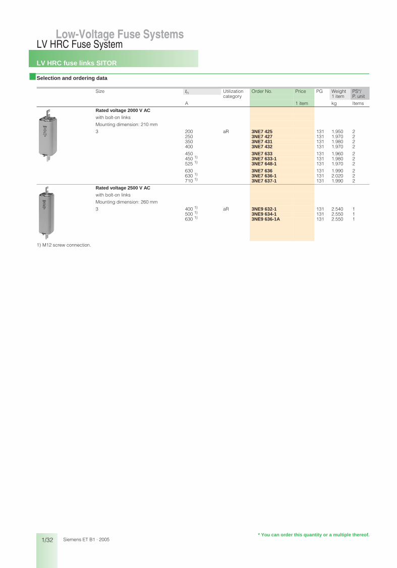
1) M12 screw connection.
Size In Utilization Order No. Price PG Weight PS*/P. unitcategory 1 item
A 1 item kg Items
Rated voltage 2000 V AC
with bolt-on links
Mounting dimension: 210 mm
3 200 aR 3NE7 425 131 1.950 2250 3NE7 427 131 1.970 2350 3NE7 431 131 1.980 2400 3NE7 432 131 1.970 2
450 3NE7 633 131 1.960 2450 1) 3NE7 633-1 131 1.980 2525 1) 3NE7 648-1 131 1.970 2
630 3NE7 636 131 1.990 2630 1) 3NE7 636-1 131 2.020 2710 1) 3NE7 637-1 131 1.990 2
Rated voltage 2500 V AC
with bolt-on links
Mounting dimension: 260 mm
3 400 1) aR 3NE9 632-1 131 2.540 1500 1) 3NE9 634-1 131 2.550 1630 1) 3NE9 636-1A 131 2.550 1
* You can order this quantity or a multiple thereof.
bet_01_04.fm Seite 32 Mittwoch, 16. Februar 2005 9:30 09

LV HRC fuse bases
1/33
LV HRC Fuse SystemLow-Voltage Fuse Systems 1
345678910
1213
Siemens ET B1 · 2005
■ Selection and ordering data
Size In Version Order No. Price PG Weight PS*/ P. unit1 item
A 1 item kg Items
LV HRC fuse bases000/00 160 1-pole
with flat terminations, screw 3NH3 030 014 0.235 3with clamp-type terminal connections 3NH3 031 014 0.230 3with saddle-type terminal connections 3NH3 032 014 0.266 3
160 with flat terminations and terminal strip 3NH3 035 014 0.230 3with flat terminations, nut 3NH3 038 014 0.207 3with flat and saddle-type terminal conn. 3NH3 050 014 0.227 3
made of molded plastic, for standard rail mounting and screw fixing
160 with flat terminations, screw 3NH3 051 014 0.160 1with saddle-type terminal connections 3NH3 052 014 0.190 1
125 with box terminal, up to 50 mm2 3NH3 053 014 0.155 1
160 3-pole, with phase barrierswith flat terminations 3NH4 030 014 0.700 1with clamp-type terminal connections 3NH4 031 014 0.800 1with saddle-type terminal connections 3NH4 032 014 0.800 1
with flat terminations and terminal strip 3NH4 035 014 0.750 1
0 160 1-polewith flat terminations 3NH3 120 014 0.460 3with clamp-type terminal connections 3NH3 122 014 0.460 3
1 250 1-polewith flat terminations 3NH3 230 014 0.789 3with double busbar connections 3NH3 220 014 0.789 3
250 3-polewith flat terminations 3NH4 230 014 2.100 1
2 400 1-polewith flat terminations 3NH3 330 014 0.843 1with double busbar connections 3NH3 320 014 1.000 1
3 630 1-polewith flat terminations 3NH3 430 014 1.100 1with double busbar connections 3NH3 420 014 1.100 1
4 1250 1-pole(IEC design) with flat terminations 3NH3 530 014 3.000 1
Low-Voltage Fuse Systems
* You can order this quantity or a multiple thereof.
bet_01_05.fm Seite 33 Mittwoch, 16. Februar 2005 9:31 09

LV HRC fuse bases
1/34
LV HRC Fuse SystemLow-Voltage Fuse Systems
Siemens ET B1 · 2005
■ Selection and ordering data
Size In Version Order No. Price PG Weight PS*/P. unit1 item
1 item kg Items
LV HRC bus-mounting bases for busbars for busbars 12 mm x 5 mm to 12 mm x 10 mm busbar clearance 40 mm
000/00 160 1-polewith saddle-type terminal connection, top 3NH3 036 014 0.150 1/3
bottom 3NH3 037 014 0.150 1/3Terminal strip, top 3NH3 048 014 0.150 1
000/00 80 3-pin, tandem design3 outgoing feeders, top and bottom with saddle-type terminal connectionwith 4 phase barriers 3NH4 037 014 0.800 1with 2 non-interrupted phase barriers 3NH4 045 014 0.800 1
LV HRC fuse bases with slewing equipmentDegree of pollution 3 Degree of protection: open IP10, closed IP201-pole, with flat termination
000/00 160 with additional saddle-type terminal connections supplied
with screw fixing for mounting plate 3NH7 030 014 1.000 1/3with claw fixing for non-perforated busbar 3NH7 031 014 1.000 1/3with screw fixing for perforated busbar 3NH7 032 014 1.000 1/3
1 250 with screw fixing for mounting plate 3NH7 230 014 2.500 1with claw fixing for non-perforated busbar 3NH7 231 014 2.500 1with screw fixing for perforated busbar 3NH7 232 014 2.500 1
2/3 400 and 630
with screw fixing for mounting plate 3NH7 330 014 4.800 1with claw fixing for non-perforated busbar 3NH7 331 014 4.800 1
with screw connection for perforated busbar, can be used as disconnector
3NH7 332 014 4.800 1
4 A 1250 with screw fixing for mounting plate 3NH7 520 014 5.200 1
* You can order this quantity or a multiple thereof.
bet_01_05.fm Seite 34 Mittwoch, 16. Februar 2005 9:31 09
LV HRC fuse bases
1/35
LV HRC Fuse SystemLow-Voltage Fuse Systems 1
345678910
1213
Siemens ET B1 · 2005
■ Selection and ordering data
Size Order No. Price PG Weight PS*/P. unit1 item
1 item kg Items
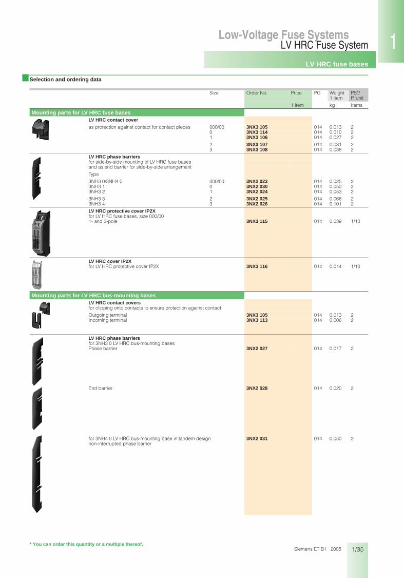
Mounting parts for LV HRC fuse basesLV HRC contact cover
as protection against contact for contact pieces 000/00 3NX3 105 014 0.013 20 3NX3 114 014 0.010 21 3NX3 106 014 0.027 2
2 3NX3 107 014 0.031 23 3NX3 108 014 0.038 2
LV HRC phase barriersfor side-by-side mounting of LV HRC fuse basesand as end barrier for side-by-side arrangement
Type
3NH3 0/3NH4 0 000/00 3NX2 023 014 0.025 23NH3 1 0 3NX2 030 014 0.050 23NH3 2 1 3NX2 024 014 0.053 2
3NH3 3 2 3NX2 025 014 0.066 23NH3 4 3 3NX2 026 014 0.101 2
LV HRC protective cover IP2Xfor LV HRC fuse bases, size 000/001- and 3-pole 3NX3 115 014 0.039 1/10
LV HRC cover IP2Xfor LV HRC protective cover IP2X 3NX3 116 014 0.014 1/10
Mounting parts for LV HRC bus-mounting basesLV HRC contact covers for clipping onto contacts to ensure protection against contact
Outgoing terminal 3NX3 105 014 0.013 2Incoming terminal 3NX3 113 014 0.006 2
LV HRC phase barriers for 3NH3 0 LV HRC bus-mounting bases Phase barrier 3NX2 027 014 0.017 2
End barrier 3NX2 028 014 0.020 2
for 3NH4 0 LV HRC bus-mounting base in tandem design 3NX2 031 014 0.050 2non-interrupted phase barrier
* You can order this quantity or a multiple thereof.
bet_01_05.fm Seite 35 Mittwoch, 16. Februar 2005 9:31 09

LV HRC fuse bases
1/36
LV HRC Fuse SystemLow-Voltage Fuse Systems
Siemens ET B1 · 2005
■ Selection and ordering data
■ Selection and ordering data
Size Order No. Price PG Weight PS*/P. unit1 item
1 item kg Items
Mounting parts for LV HRC fuses Fuse puller 000 to 4for LV HRC fuse links
without sleeve 3NX1 013 014 0.280 1
with sleeve 3NX1 014 014 0.480 1
Isolating linkfor LV HRC fuse bases and fuse switch disconnectors
with insulated grip lugs
silver-plated 000/00 3NG1 002 014 0.080 1/60 3NG1 102 014 0.110 1/6
1 3NG1 202 014 0.170 1/32 3NG1 302 014 0.240 1/33 3NG1 402 014 0.290 1/3
with non-insulated grip lugs
tinned 4 3NG1 503 014 0.708 1/6nickel-plated 4a 3NG1 505 014 0.730 1/3
Fuse base cover
for LV HRC fuse bases 000/00 3NX1 003 014 0.050 3according to DIN 43620 1, 2, 3 3NX1 004 014 0.100 3red with yellow information label "power supply isolating point"
LV HRC signal detectors
Size Order No. Price PG Weight PS*/P. unit1 item
1 item kg Items
LV HRC signal detector 000 to 4 3NX1 021 014 0.036 1/4for LV HRC fuse links with non-insulated grip lugs Rated voltage to 690 V ACContact: Microswitch 250 V AC, 6 AConnection: Flat connector 2.3 mm ... 0.5 mm
Signal detector link 000 to 4Response value > 9 V; 2.5 A; for standard applications 3NX1 022 014 0.015 1/12Response value > 2 V; 7 A; only for meshed systems 3NX1 023 014 0.015 1/12
� � �
* You can order this quantity or a multiple thereof.
bet_01_05.fm Seite 36 Mittwoch, 16. Februar 2005 9:31 09

LV HRC fuse switch disconnectorsfor power distribution
1/37
LV HRC Fuse SystemLow-Voltage Fuse Systems 1
345678910
1213
Siemens ET B1 · 2005
Low-Voltage Fuse Systems
■ Selection and ordering data
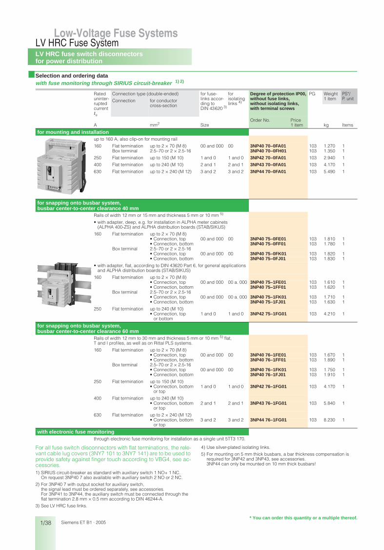
For all fuse switch disconnectors with flat terminations, the relevant cable lug covers (3NY7 101 to 3NY7 141) are to be used to provide safety against finger touch according to VBG4, see accessories.1) See LV HRC fuse links.
2) Use silver-plated isolating links.
3) 125/160 A only possible with 21 mm 3NY1 822 (125 A) and 3NY1 824 (160 A)fuse links, see accessories.
4) Corresponds to size 00 with maximum width 21 mm (according to IEC 60269-2-1 and DIN 43620).
5) For mounting on 5 mm thick busbars, a bar thickness compensation is required for 3NP42 and 3NP43, see accessories. 3NP44 can only be mounted on 10 mm thick busbars!
6) No further cover required for 3NP40 with box terminal.
Rateduninter-ruptedcurrent Iu
A
Connection type (double-ended) for fuse links acc. to DIN 43620 1)
Size
for isolating links 2)
Degree of protection IP00, without fuse links, without isolating links, with terminal screws
PG Weight PS*/P. unitConnection for conductor
cross-section
1 item
mm2
Order No. Price
1 item kg Items
for mounting and installation
3NP40 10
3NP40 70
3NP42 70
up to 160 A, also clip-on for mounting rail
160 3) Box terminal 1.5–50 0004 00 3NP40 10–0CH01 103 0.512 1
160 Flat termination up to 2 × 70 (M 8) 00 and 000 00 3NP40 70–0CA01 103 0.749 1Box terminal 2.5–70 or 2 × 2.5-16 3NP40 70–0CH01 103 0.800 1
250 Flat termination up to 150 (M 10) 1 and 0 1 and 0 3NP42 70–0CA01 103 2.430 1
400 Flat termination up to 240 (M 10) 2 and 1 2 and 1 3NP43 70–0CA01 103 3.610 1
630 Flat termination up to 2 × 240 (M 12) 3 and 2 3 and 2 3NP44 70–0CA01 103 4.980 1
for snapping onto busbar system, busbar center-to-center clearance 40 mmRails of width 12 mm or 15 mm and thickness 5 mm or 10 mm 5)
• with adapter, deep, e.g. for installation in ALPHA meter cabinets (ALPHA 400-ZS) and ALPHA distribution boards (STAB/SIKUS)
160 3) Box terminal 1.5–50• Connection, top 000 4) 00 3NP40 15–0CK01 103 0.952 1• Connection, bottom 3NP40 15–0CJ01 103 0.970 1
160 Flat termination up to 2 × 70 (M 8)• Connection, top 00 and 000 00 3NP40 75–0CE01 103 1.210 1• Connection, bottom 3NP40 75–0CF01 103 1.240 1
Box terminal 2.5–70 or 2 × 2.5-16• Connection, top 00 and 000 00 3NP40 75–0CK01 103 1.290 1• Connection, bottom 3NP40 75–0CJ01 103 1.270 1
• with adapter, flat, according to DIN 43620 Part 6, for general applications and ALPHA distribution boards (STAB/SIKUS)
160 3) Box terminal 1.5–50• Connection, top 000 4) 00 3NP40 15–1CK01 103 0.892 1• Connection, bottom 3NP40 15–1CJ01 103 0.888 1
160 Flat termination up to 2 × 70 (M 8)• Connection, top 00 and 000 00 and 000 3NP40 75–1CE01 103 1.180 1• Connection, bottom 3NP40 75–1CF01 103 1.180 1
Box terminal 2.5–70 or 2 × 2.5-16• Connection, top 00 and 000 00 and 000 3NP40 75–1CK01 103 1.260 1• Connection, bottom 3NP40 75–1CJ01 103 1.210 1
250 Flat termination up to 240 (M 10)• Connection bottom
or top1 and 0 1 and 0 3NP42 75–1CG01 103 3.710 1
for snapping onto busbar system, busbar center-to-center clearance 60 mm
3NP40 16
3NP42 76
Rails of width 12 mm to 30 mm and thickness 5 mm or 10 mm 5)
flat, T and I profiles, as well as on Rittal PLS systems.
160 3) Box terminal 6) 1.5–50• Connection, top 000 4) 00 3NP40 16–1CK01 103 0.916 1• Connection, bottom 3NP40 16–1CJ01 103 0.950 1
160 Flat termination up to 2 × 70 (M 8)• Connection, top 00 and 000 00 3NP40 76–1CE01 103 1.200 1• Connection, bottom 3NP40 76–1CF01 103 1.200 1
Box terminal 6) 2.5–70 or 2 × 2.5-16• Connection, top 00 and 000 00 3NP40 76–1CK01 103 1.290 1• Connection, bottom 3NP40 76–1CJ01 103 1.240 1
250 Flat termination up to 150 (M 10)• Connection, bottom
or top1 and 0 1 and 0 3NP42 76–1CG01 103 3.710 1
400 Flat termination up to 240 (M 10)• Connection, bottom
or top2 and 1 2 and 1 3NP43 76–1CG01 103 5.440 1
630 Flat termination up to 2 × 240 (M 12)• Connection, bottom
or top3 and 2 3 and 2 3NP44 76–1CG01 103 7.680 1
* You can order this quantity or a multiple thereof.
bet_01_06.fm Seite 37 Mittwoch, 16. Februar 2005 9:32 09
LV HRC fuse switch disconnectorsfor power distribution
1/38
LV HRC Fuse SystemLow-Voltage Fuse Systems
Siemens ET B1 · 2005
■ Selection and ordering datawith fuse monitoring through SIRIUS circuit-breaker 1) 2)
For all fuse switch disconnectors with flat terminations, the rele-vant cable lug covers (3NY7 101 to 3NY7 141) are to be used to provide safety against finger touch according to VBG4, see ac-cessories.1) SIRIUS circuit-breaker as standard with auxiliary switch 1 NO+ 1 NC.
On request 3NP40 7 also available with auxiliary switch 2 NO or 2 NC.
2) For 3NP40 7 with output socket for auxiliary switch,the signal lead must be ordered separately, see accessories.For 3NP41 to 3NP44, the auxiliary switch must be connected through the flat termination 2.8 mm × 0.5 mm according to DIN 46244-A.
3) See LV HRC fuse links.
4) Use silver-plated isolating links.
5) For mounting on 5 mm thick busbars, a bar thickness compensation is required for 3NP42 and 3NP43, see accessories. 3NP44 can only be mounted on 10 mm thick busbars!
Rateduninter-ruptedcurrent Iu
Connection type (double-ended) for fuse- links accor- ding to DIN 43620 3)
for isolating links 4)
Degree of protection IP00, without fuse links, without isolating links, with terminal screws
PG Weight PS*/P. unitConnection for conductor
cross-section
1 item
A mm2 SizeOrder No. Price
1 item kg Items
for mounting and installationup to 160 A, also clip-on for mounting rail
160 Flat termination up to 2 × 70 (M 8) 00 and 000 00 3NP40 70–0FA01 103 1.270 1Box terminal 2.5–70 or 2 × 2.5-16 3NP40 70–0FH01 103 1.350 1
250 Flat termination up to 150 (M 10) 1 and 0 1 and 0 3NP42 70–0FA01 103 2.940 1
400 Flat termination up to 240 (M 10) 2 and 1 2 and 1 3NP43 70–0FA01 103 4.170 1
630 Flat termination up to 2 × 240 (M 12) 3 and 2 3 and 2 3NP44 70–0FA01 103 5.490 1
for snapping onto busbar system, busbar center-to-center clearance 40 mm
Rails of width 12 mm or 15 mm and thickness 5 mm or 10 mm 5)
• with adapter, deep, e.g. for installation in ALPHA meter cabinets (ALPHA 400-ZS) and ALPHA distribution boards (STAB/SIKUS)
160 Flat termination up to 2 × 70 (M 8)• Connection, top 00 and 000 00 3NP40 75–0FE01 103 1.810 1• Connection, bottom 3NP40 75–0FF01 103 1.780 1
Box terminal 2.5–70 or 2 × 2.5-16• Connection, top 00 and 000 00 3NP40 75–0FK01 103 1.820 1• Connection, bottom 3NP40 75–0FJ01 103 1.830 1
• with adapter, flat, according to DIN 43620 Part 6, for general applications and ALPHA distribution boards (STAB/SIKUS)
160 Flat termination up to 2 × 70 (M 8)• Connection, top 00 and 000 00 a. 000 3NP40 75–1FE01 103 1.610 1• Connection, bottom 3NP40 75–1FF01 103 1.620 1
Box terminal 2.5–70 or 2 × 2.5-16• Connection, top 00 and 000 00 a. 000 3NP40 75–1FK01 103 1.710 1• Connection, bottom 3NP40 75–1FJ01 103 1.630 1
250 Flat termination up to 240 (M 10)• Connection, top
or bottom1 and 0 1 and 0 3NP42 75–1FG01 103 4.210 1
for snapping onto busbar system, busbar center-to-center clearance 60 mm
Rails of width 12 mm to 30 mm and thickness 5 mm or 10 mm 5) flat,T and I profiles, as well as on Rittal PLS systems.
160 Flat termination up to 2 × 70 (M 8)• Connection, top 00 and 000 00 3NP40 76–1FE01 103 1.670 1• Connection, bottom 3NP40 76–1FF01 103 1.890 1
Box terminal 2.5–70 or 2 × 2.5-16• Connection, top 00 and 000 00 3NP40 76–1FK01 103 1.750 1• Connection, bottom 3NP40 76–1FJ01 103 1.910 1
250 Flat termination up to 150 (M 10)• Connection, bottom
or top1 and 0 1 and 0 3NP42 76–1FG01 103 4.170 1
400 Flat termination up to 240 (M 10)• Connection, bottom
or top2 and 1 2 and 1 3NP43 76–1FG01 103 5.840 1
630 Flat termination up to 2 × 240 (M 12)• Connection, bottom
or top3 and 2 3 and 2 3NP44 76–1FG01 103 8.230 1
with electronic fuse monitoringthrough electronic fuse monitoring for installation as a single unit 5TT3 170.
* You can order this quantity or a multiple thereof.
bet_01_06.fm Seite 38 Mittwoch, 16. Februar 2005 9:32 09

LV HRC fuse switch disconnectorsfor power distribution
1/39
LV HRC Fuse SystemLow-Voltage Fuse Systems 1
345678910
1213
Siemens ET B1 · 2005
■ Accessories
1) The fuse switch disconnector with mounted cable lug covers, together with molded-plastic masking frame for distributor/device field/incoming feeder unit, is easy to install in the meter cabinet.
for fuse switch disconnectors
Version Order No. Price PG Weight PS*/P. unit1 item
1 item kg Items
3NY1 995
Quick retaining plate between 2 mounting rails according toDIN EN 50022 and DIN EN 50023
Busbar center-to-center clearance 125 mm 3NP40 10.3NP40 70
3NY1 995 103 0.135 1
Busbar center-to-center clearance 125 mm 3NP42 70 3NY7 322 103 0.249 1
Cable lug covers and finger touch cover according to VBG 4 (1 set=2 items)for 1 mounting or2 adapter devices
3NP40 7 with flat termination 1) 3NY7 101 103 0.065 1 set3NP42 7 3NY7 121 103 0.220 1 set3NP43 3NY7 131 103 0.221 1 set3NP44 3NY7 141 103 0.319 1 set
Connection terminals (1 set=3 items)
Conductor cross-section
3NP42 7 70 mm2–150 mm2 3NY7 120 103 0.333 1 set
3NP43 120 mm2–240 mm2 3NY7 130 103 0.583 1 set
3NP44 150 mm2–300 mm2 3NY7 140 103 0.725 1 set
3NY7 102
Triple terminal Conductor cross-section(1 set = 3 items) • solid/stranded:
2.5 mm2–16 mm2
• solid with end sleeve: 2.5 mm2–10 mm2
for mounting on box terminals
3NP40 13NP40 7
3NY7 102 103 0.131 1 set
for mounting onflat terminations
3NP40 7 3NY7 105 103 0.113 1 set
3NY1 263
3NY1 237
3NY1 238
3-phase busbar 3NP40 1 for Iu max = 225 AModular width 90 mm = 5 MW for 2 switch disconnectors 3NY1 237 103 0.265 1Permissible connection 25 mm2
or supply terminalfor 3 switch disconnectors 3NY1 238 103 0.434 1for 4 switch disconnectors 3NY1 438 103 0.650 1connecting bar 3NY1 263 103 0.267 1
Capfor 1 blank space in 3NY1 238
3NP40 1 3NY1 265 103 0.012 1
Feeder terminal 3NP40 1 Conductor cross-section 3NY1 236 103 0.262 1 set(1 set = 3 items) for Iu max = 225 A
• solid/stranded: 25 mm2–95 mm2
• solid with end sleeve: 16 mm2–70 mm2
Overreaching protection 3NP42 73NP43.3NP44
3NY7 481 103 0.021 1
3NY7 481 Sealing pin(1 pack = 10 items)
3NP42 73NP43.3NP44
3NY7 482 103 0.056 10
Busbar thickness compensation(1 assembly kit = 5 items) for 5 mm busbars only
3NP42 73NP43
3NY7 381 103 0.064 1 set
Handle unit 3NP40 1 3NY7 003 103 0.160 1gray with inscription labelwith voltage inspection holes
3NP40 7 3NY7 001 103 0.220 1
3NY3 035
Auxiliary switch 1 CO 3NP40 1 to 3NP44 3NY3 035 103 0.004 1for sizes 000 and 00 with self-tapping screws for sizes 1 to 3 to clip on
electronically optimized 3NY3 030 103 0.004 1
fuse links size 000 3NP40 1 400 V/125 A 3NY1 822 103 0.130 1with non-insulated grip lugs, utilization category gL/gG for cable and line protection, overall width 21 mm according to IEC 60269-2-1 and DIN 43620
400 V/160 A 3NY1 824 103 0.129 1
Signal lead for connection to output socket of fuse monitoring size 001-m cable with connector 3NP40 7 3NY1 910 103 0.097 13-m cable with connector 3NP40 7 3NY1 911 103 0.261 1
��������
* You can order this quantity or a multiple thereof.
bet_01_06.fm Seite 39 Mittwoch, 16. Februar 2005 9:32 09

LV HRC fuse switch disconnectorsfor power distribution
1/40
LV HRC Fuse SystemLow-Voltage Fuse Systems
Siemens ET B1 · 2005
■ Accessories
Covers
See also catalog "Molded-plastic distribution system 8HP", Order No. 8ZX1012-0HP54-5AB1.1) For installation in ALPHA wall and floor-mounted distribution boards and
meters cabinets (STAB, SIKUS, SIPRO), special covers are sometimes required, see accessories.
2) The 3NY7 220 molded-plastic cover (for installation in any distribution board) can also be used with 8GE3 818-0 mounting plate.
for fuse switch disconnectors
Height × Width
Order No. Price PG Weight1 item
PS*/ P. unit
mm 1 item kg Items
for installation in any distribution board 1)
3NY1 251
Molded-plastic covers 3NP40 1 215 × 130 3NY1 251 103 0.052 13NP40 7 with box terminals 215 × 130 3NY7 200 103 0.037 13NP40 7 with flat termination 215 × 130 3NY7 201 103 0.046 1
3NP42 7 375 × 220 3NY7 220 103 0.112 13NP43 375 × 245 3NY7 230 103 0.117 13NP44 375 × 290 3NY7 240 103 0.125 1
for installation in ALPHA 400-ZS meter cabinets See Technical Publications "Installation and mounting", Order No. E20001–P285–A526–V1.
Molded-plastic covers
for distributor/device field
or suitable for incoming feeder unit in meter center (mounting on busbar)
2 × 3NP40 1 197 × 215.5 3NY1 258 103 0.063 1
1 × 3NP40 1 left 197 × 215.5 3NY1 262 103 0.093 11 × 3NP40 1 right 197 × 215.5 3NY1 264 103 0.091 11 × 3NP40 7 left 208 × 229 3NY7 500 103 0.120 11 × 3NP40 7 right 208 × 229 3NY7 501 103 0.120 12 × 3NP40 7 208 × 229 3NY7 502 103 0.054 1
3NP42 7 309 × 216 3NY7 220 103 0.112 13NP43 375 × 245 3NY7 230 103 0.117 13NP44 375 × 290 3NY7 240 103 0.125 1
for installation in ALPHA 160 and ALPHA 400 wall-mounted distribution boards (STAB 160/STAB 400) and ALPHA 630 floor-mounted distribution board (SIKUS 630)
Molded-plastic covers
for attachment on mounting plate or busbars
for further information, see catalog ET A1 "ALPHA distribution boards"
1 × 3NP40 1 right 166 × 199 3NY1 260 103 0.082 11 × 3NP40 1 left 166 × 199 3NY1 261 103 0.086 12 × 3NP40 1 166 × 199 3NY1 248 103 0.036 1
1 × 3NP40 7 left 208 × 229 3NY7 500 103 0.120 11 × 3NP40 7 right 208 × 229 3NY7 501 103 0.120 12 × 3NP40 7 208 × 236 3NY7 502 103 0.054 1
3NP42 7 309 × 216 2) 3NY7 820 103 0.113 13NP43 375 × 245 3NY7 230 103 0.117 13NP44 375 × 290 3NY7 240 103 0.125 1
for installation in STAB/SIKUS Universal 8GFCovers and fuse assemblies are available for all switch disconnectors for fuse links, sizes 000 to 3.Order Nos. and prices on request.
for fuse switch disconnectors
8HP casing Order No. Price PG Weight PS*/P. unit1 item
Size 1 item kg Items
for installation in molded-plastic distribution system SENTRIC 8HPMolded-plastic covers
for installation in 8HP complete casing with fuse switch disconnectors
1 × 3NP40 10 1 8HP6 431 046 0.221 11 × 3NP40 70 1 8HP6 422 046 0.224 1
2 × 3NP40 10 2 8HP6 432 046 0.465 13 × 3NP40 10 2 8HP6 432 046 0.465 11 × 3NP40 70 2 8HP6 423 046 0.230 12 × 3NP40 70 2 8HP6 424 046 0.203 1
1 × 3NP40 70 2.5 8HP6 423 046 0.230 12 × 3NP40 70 2.5 8HP6 424 046 0.203 11 × 3NP42 70 2.5 8HP6 427 046 0.250 1
�����
����
* You can order this quantity or a multiple thereof.
bet_01_06.fm Seite 40 Mittwoch, 16. Februar 2005 9:32 09
LV HRC fuse switch disconnectorsfor power distribution
1/41
LV HRC Fuse SystemLow-Voltage Fuse Systems 1
345678910
1213
Siemens ET B1 · 2005
■ Accessories
Covers
1) For mounting on 8GD9 590 mounting plate, the 3NY7 220 molded-plastic cover can also be used.
for fuse switch disconnectors
Height × Width
Order No. Price PG Weight PS*/P. unit1 item
mm 1 item kg Items
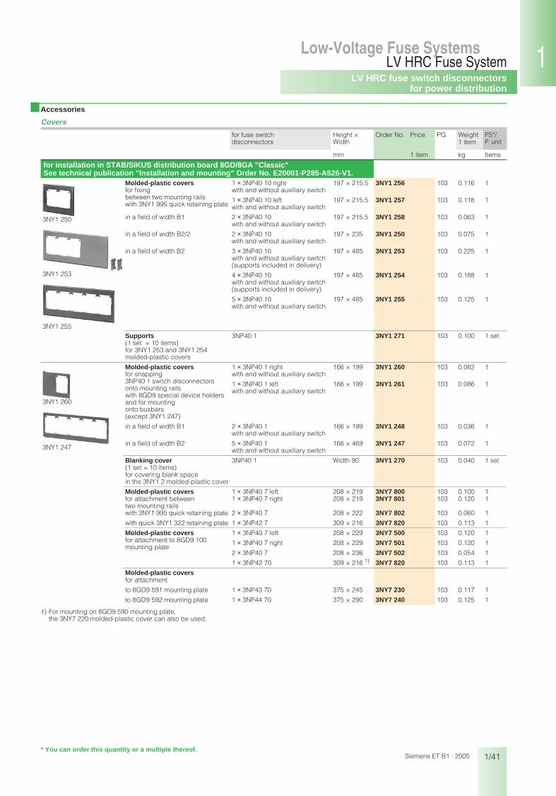
for installation in STAB/SIKUS distribution board 8GD/8GA "Classic" See technical publication "Installation and mounting" Order No. E20001-P285-A526-V1.
3NY1 250
3NY1 253
3NY1 255
Molded-plastic covers for fixing between two mounting rails with 3NY1 995 quick retaining plate
1 × 3NP40 10 right with and without auxiliary switch
197 × 215.5 3NY1 256 103 0.116 1
1 × 3NP40 10 left with and without auxiliary switch
197 × 215.5 3NY1 257 103 0.118 1
in a field of width B1 2 × 3NP40 10 with and without auxiliary switch
197 × 215.5 3NY1 258 103 0.063 1
in a field of width B2/2 2 × 3NP40 10 with and without auxiliary switch
197 × 235 3NY1 250 103 0.075 1
in a field of width B2 3 × 3NP40 10 with and without auxiliary switch (supports included in delivery)
197 × 485 3NY1 253 103 0.225 1
4 × 3NP40 10 with and without auxiliary switch (supports included in delivery)
197 × 485 3NY1 254 103 0.188 1
5 × 3NP40 10 with and without auxiliary switch
197 × 485 3NY1 255 103 0.125 1
Supports 3NP40 1 3NY1 271 103 0.100 1 set(1 set = 10 items) for 3NY1 253 and 3NY1 254 molded-plastic covers
3NY1 260
3NY1 247
Molded-plastic covers for snapping 3NP40 1 switch disconnectorsonto mounting rails with 8GD9 special device holders and for mounting onto busbars (except 3NY1 247)
1 × 3NP40 1 right with and without auxiliary switch
166 × 199 3NY1 260 103 0.082 1
1 × 3NP40 1 left with and without auxiliary switch
166 × 199 3NY1 261 103 0.086 1
in a field of width B1 2 × 3NP40 1 with and without auxiliary switch
166 × 199 3NY1 248 103 0.036 1
in a field of width B2 5 × 3NP40 1 with and without auxiliary switch
166 × 469 3NY1 247 103 0.072 1
Blanking cover 3NP40 1 Width 90 3NY1 270 103 0.040 1 set(1 set = 10 items) for covering blank space in the 3NY1 2 molded-plastic cover
Molded-plastic covers 1 × 3NP40 7 left 208 × 219 3NY7 800 103 0.100 1for attachment between two mounting rails
1 × 3NP40 7 right 208 × 219 3NY7 801 103 0.120 1
with 3NY1 995 quick retaining plate 2 × 3NP40 7 208 × 222 3NY7 802 103 0.060 1
with quick 3NY1 322 retaining plate 1 × 3NP42 7 309 × 216 3NY7 820 103 0.113 1
Molded-plastic covers 1 × 3NP40 7 left 208 × 229 3NY7 500 103 0.120 1for attachment to 8GD9 100mounting plate
1 × 3NP40 7 right 208 × 229 3NY7 501 103 0.120 1
2 × 3NP40 7 208 × 236 3NY7 502 103 0.054 1
1 × 3NP42 70 309 × 216 1) 3NY7 820 103 0.113 1
Molded-plastic coversfor attachment
to 8GD9 591 mounting plate 1 × 3NP43 70 375 × 245 3NY7 230 103 0.117 1
to 8GD9 592 mounting plate 1 × 3NP44 70 375 × 290 3NY7 240 103 0.125 1
* You can order this quantity or a multiple thereof.
bet_01_06.fm Seite 41 Mittwoch, 16. Februar 2005 9:32 09

LV HRC fuse switch disconnectorsfor advanced technical demands
1/42
LV HRC Fuse SystemLow-Voltage Fuse Systems
Siemens ET B1 · 2005
■ Selection and ordering data
completely compartmentalized, with high speed closing feature
1) See LV HRC fuse links.
2) According to DIN 46234 or 16 mm2–95 mm2 according to DIN 46235 (use lug M 10 if required).
3) If auxiliary switch is retrofitted, additional drill holes are required on the switch.
4) According to DIN 46234 or DIN 46235; with lug according to DIN 46235: min. conductor cross-section 16 mm2 (use lug M 12 if required).
5) For accessories and additional devices on busbar systems, see accessories and distribution board, busbar systems and switchgear.
6) For 3NP50 60 with flat terminations, the relevant 3NY1 106 cable lug cov-ers must be used (see accessories) for the purpose of protection against finger contact according to DIN VDE 0106 Part 100.
Rateduninter-ruptedcurrent Iu
Connection type (double-ended) for fuse links according to DIN 43620 1)
for isolating links
Auxiliary switch on switch dis-connector
Degree of protection IP00, without fuse links, without isolating links, with terminal screws
PG Weight PS*/P. unitConnection for conductor
cross-section
1 item
Order No. Price
A mm2 Size Size Version 1 item kg Items
for mounting and installation160 Flat termination 6) 2.5–150 2) 00 and 000 00 without 3) 3NP50 60–0CA00 103 1.600 1
1 NO + 1 NC 3NP50 60–0CA10 103 1.650 1
Clamp connections
1 wire 00 and 000 00 without 3) 3NP50 60–0CB00 103 1.730 12.5–50 or 2-wire 1× 2.5–50 1× 2.5–35
1 NO + 1 NC 3NP50 60–0CB10 103 1.740 1
250 Flat termination 6–150 4) 1 and 0 1 without 3NP52 60–0CA00 103 5.470 11 NO + 1 NC 3NP52 60–0CA10 103 5.490 1
Clamp connections
35–120 1 and 0 1 without 3NP52 60–0CB00 103 5.600 11 NO + 1 NC 3NP52 60–0CB10 103 5.810 1
400 Flat termination 6–240 4) 2 and 1 2 without 3NP53 60–0CA00 103 6.530 11 NO + 1 NC 3NP53 60–0CA10 103 6.550 1
630 Flat termination 6–2 × 240 4) 3 and 2 3 without 3NP54 60–0CA00 103 7.940 11 NO + 1 NC 3NP54 60–0CA10 103 7.950 1
for adaptation to busbar systems 5), busbar center-to-center clearance 40 mm
rails of width 12 mm and thickness 5 mm or 10 mm
160 Flat termination 2.5-150 2) 00 and 000 without 3NP50 65–1CF00 103 2.380 1Connection, bottom
1 NO + 1 NC 3NP50 65–1CF10 103 2.370 1
Clamp connections
1 wire 00 and 000 without 3NP50 65–1CG00 103 2.430 12.5–50 or 2-wire 1× 2.5–50 1× 2.5–35 Connection, bottom
1 NO + 1 NC 3NP50 65–1CG10 103 2.430 1
for adaptation to busbar systems 5), busbar center-to-center clearance 60 mm
Use switch version "Mounting and installation" and busbar adapter, see accessories.
* You can order this quantity or a multiple thereof.
bet_01_06.fm Seite 42 Mittwoch, 16. Februar 2005 9:32 09

LV HRC fuse switch disconnectorsfor advanced technical demands
1/43
LV HRC Fuse SystemLow-Voltage Fuse Systems 1
345678910
1213
Siemens ET B1 · 2005
■ Selection and ordering data
completely compartmentalized, with high speed closing feature with fuse monitoring through SIRIUS circuit-breaker 1)
1) SIRIUS circuit-breaker on request, also auxiliary switch 2 NC.
2) See LV HRC fuse links
3) According to DIN 46234 or 16 mm2–95 mm2 according to DIN 46235 (use lug M 10 if required).
4) According to DIN 46234 or DIN 46235; with lug according to DIN 46235: min. conductor cross-section 16 mm2 (use lug M 12 if required).
5) For accessories and additional devices on busbar systems,see accessories and distribution board, busbar systems and switchgear.
6) For 3NP50 60 with flat terminations, the relevant 3NY1 106 cable lug cov-ers must be used (see accessories) for the purpose of protection against finger contact according to DIN VDE 0106 Part 100.
Rateduninter-ruptedcurrent Iu
Connection type (double-ended) for fuse links acc. to DIN 43620 2)
Auxiliary switch on switch dis-connector
Auxiliary switch on circuit-breaker
Degr. of protection IP00, without fuse links, without isolating links, with terminal screws
PG Weight PS*/P. unitConnection for conductor
cross-section
1 item
Order No. Price
A mm2 Size Version Version 1 item kg Items
for mounting and installationwith plug-in connection of the auxiliary switch connecting cable (length approx. 1 m) to the circuit-breaker
160 Flat termination 6) 2.5–150 3) 00 and 000 1 NO + 1 NC 1 NO + 1 NC 3NP50 60–0EA86 103 2.480 11 NO + 1 NC 2 NO 3NP50 60–0EA26 103 2.550 1
Clamp connections
1-wire 00 and 000 1 NO + 1 NC 1 NO + 1 NC 3NP50 60–0EB86 103 2.610 12.5–50 2-wire 1× 2.5–50 1× 2.5–35
1 NO + 1 NC 2 NO 3NP50 60–0EB26 103 2.650 1
250 Flat termination 6–150 4) 1 and 0 1 NO + 1 NC 1 NO + 1 NC 3NP52 60–0EA86 103 6.010 11 NO + 1 NC 2 NO 3NP52 60–0EA26 103 6.860 1
Clamp connections
35–120 1 and 0 1 NO + 1 NC 1 NO + 1 NC 3NP52 60–0EB86 103 7.090 11 NO + 1 NC 2 NO 3NP52 60–0EB26 103 6.650 1
400 Flat termination 6–240 4) 2 and 1 1 NO + 1 NC 1 NO + 1 NC 3NP53 60–0EA86 103 7.080 11 NO + 1 NC 2 NO 3NP53 60–0EA26 103 5.410 1
630 Flat termination 6–2 × 240 4) 3 and 2 1 NO + 1 NC 1 NO + 1 NC 3NP54 60–0EA86 103 8.460 11 NO + 1 NC 2 NO 3NP54 60–0EA26 103 9.230 1
for adaptation to busbar systems 5), busbar center-to-center clearance 40 mm
for rails of width 12 mm and thickness 5 mm or 10 mm
160 Flat termination 2.5–150 3) 00 and 000 1 NO + 1 NC 1 NO + 1 NC 3NP50 65–1EF86 103 2.900 1Connection, bottom
1 NO + 1 NC 2 NO 3NP50 65–1EF26 103 2.950 1
Clamp connections
1-wire 00 and 000 1 NO + 1 NC 1 NO + 1 NC 3NP50 65–1EG86 103 3.020 12.5–50 2-wire 1× 2.5–50 1× 2.5–35 Connection, bottom
1 NO + 1 NC 2 NO 3NP50 65–1EG26 103 2.970 1
for adaptation to busbar systems 5), busbar center-to-center clearance 60 mm
Use switch version "Mounting and installation" and busbar adapter, see accessories.
* You can order this quantity or a multiple thereof.
bet_01_06.fm Seite 43 Mittwoch, 16. Februar 2005 9:32 09

LV HRC fuse switch disconnectorsfor advanced technical demands
1/44
LV HRC Fuse SystemLow-Voltage Fuse Systems
Siemens ET B1 · 2005
■ Selection and ordering data
completely compartmentalized, with high speed closing feature with electronic fuse monitoring ESÜ (self-powered) Version "A" (open-circuit principle) 1) for rated operational voltage Ue from 400 V to 500 V Incoming supply must come from above!
1) Version "R" (closed-circuit principle) on request! (See also block diagram).
2) See LV HRC fuse links.
3) According to DIN 46234 or 16 mm2–95 mm2 according to DIN 46235 (use lug M 10 if required).
4) According to DIN 46234 or DIN 46235; with lug according to DIN 46235: min. conductor cross-section 16 mm2 (use lug M 12 if required).
5) For 3NP50 60 with flat terminations, the relevant 3NY1 106 cable lug cov-ers must be used (see accessories) for the purpose of protection against finger contact according to DIN VDE 0106 Part 100.
Rateduninter-ruptedcurrent Iu
Connection type (double-ended)
for fuse links according to DIN 43620 2)
Auxiliary switch on switch dis-connector
Auxiliary switch onfusemonitoring
Degree of protection IP00, without fuse links, with-out isolating links, with terminal screws
PG Weight 1 item
PS*/P. unit
Connection for conduc-tor cross-section
Order No. Price
A mm2 Size Version Version 1 item kg Items
for mounting and installationwith plug-in connection of auxiliary switch connecting cable (length approx. 1 m) for fuse monitoring status display: green LED illuminated, fault indication: green LED flashing fuse failure: red LED (display per phase)
160 Flattermination 5)
2.5–120 3) 00 and 000 1 NO + 1 NC 2 NO + 1 NC 3NP50 60–0HA13 103 2.370 1
Clamp con-nections
1-wire2.5–50 2-wire 1× 2.5–50 1× 2.5–35
00 and 000 1 NO + 1 NC 2 NO + 1 NC 3NP50 60–0HB13 103 2.500 1
250 Flattermination
6–150 4) 1 and 0 1 NO + 1 NC 2 NO + 1 NC 3NP52 60–0HA13 103 5.860 1
400 Flat termination
6–240 4) 2 and 1 1 NO + 1 NC 2 NO + 1 NC 3NP53 60–0HA13 103 6.950 1
630 Flat termination
6–240 4) 3 and 2 1 NO + 1 NC 2 NO + 1 NC 3NP54 60–0HA13 103 8.510 1
* You can order this quantity or a multiple thereof.
bet_01_06.fm Seite 44 Mittwoch, 16. Februar 2005 9:32 09

LV HRC fuse switch disconnectorsfor advanced technical demands
1/45
LV HRC Fuse SystemLow-Voltage Fuse Systems 1
345678910
1213
Siemens ET B1 · 2005
■ Selection and ordering data
completely compartmentalized, with high speed closing feature with electronic fuse monitoring ESÜ (self-powered) Version "A" (open-circuit principle) 1) for rated operational voltage Ue from 400 V to 500 V Incoming supply must come from above!
1) Version "R" (closed-circuit principle) on request! (See also ET B1 T 2005 block diagram.)
2) See LV HRC fuse links.
3) According to DIN 46234 or 16 mm2–95 mm2 according to DIN 46235 (use lug M 10 if required).
4) For accessories and additional devices on busbar systems, see accessories and components for distribution systems.
Rateduninter-ruptedcurrent Iu
Connection type (double-ended)
for fuse links according to DIN 43620 2)
Auxiliary switch on switch dis-connector
Auxiliary switch onfusemonitoring
Degree of protection IP00, without fuse links, without isolating links, with terminal screws
PG Weight 1 item
PS*/P. unit
Connection for conductor cross-section
Order No. Price
A mm2 Size Version Version 1 item kg Items
for adaptation to busbar systems 4), busbar center-to-center clearance 40 mm
for rails of width 12 mm and thickness 5 mm or 10 mm
160 Flat termination
2.5–120 3) Connection bottom
00 and 000 1 NO + 1 NC 2 NO + 1 NC 3NP50 65–1HF13 103 2.770 1
for adaptation to busbar systems 4), busbar center-to-center clearance 60 mm
Use switch version "Mounting and installation" and busbar adapter, see accessories.
* You can order this quantity or a multiple thereof.
bet_01_06.fm Seite 45 Mittwoch, 16. Februar 2005 9:32 09

LV HRC fuse switch disconnectorsfor advanced technical demands
1/46
LV HRC Fuse SystemLow-Voltage Fuse Systems
Siemens ET B1 · 2005
■ Accessories
1) Also available in 2-wire version: 1 × 2.5 mm2 to 50 mm2 and 1 × 2.5 mm2 to 35 mm2.
2) Switch is wider than adapter; however, this can be expanded to 276 mm using 2 8US19 98–2BM00 lateral modules.
for fuse switch disconnectors
Height × Width Order No. Price PG Weight PS*/P. unit1 item
mm 1 item kg Items
for installation in any distribution board
3NY1 107
3NY1 106
Molded-plastic cover for installation in cabinet
3NP50 with and without auxiliary switch
215 × 135 3NY1 105 103 0.045 1
with auxiliary switch 215 × 135 3NY1 115 103 0.044 1
Molded-plastic cover for installation in metal front panel
with and without auxiliary switch
220 × 160 3NY1 125 103 0.062 1
Molded-plastic cover for coveringconnection terminals
3NP50 with and without auxiliary switch
265 × 135 3NY1 107 103 0.073 1
Molded-plastic cover for coveringcable lug connections
3NP50 with and without auxiliary switch
290 × 135 3NY1 106 103 0.071 1
Molded-plastic cover for separate covering of top and bottomcable lug connections
with auxiliary switch 290 × 135 3NY1 116 103 0.071 1
3NP50 with and without auxiliary switch
290 × 135 3NY1 108 103 0.048 1
3NY1 212
Assembly kit forinstallationwith molded-plastic cover,fixing bracket and small components
3NP50 60 250 × 149 3NY1 208 103 0.531 1
3NP52 60 300 × 220 3NY1 210 103 0.287 1
3NP53 60 300 × 245 3NY1 211 103 0.298 1
3NP54 60 300 × 290 3NY1 212 103 0.313 1
for switches with and without auxiliary switch
3TX6 546–3B
Cover for cable lug connection(1 set = 6 items) screw ontofree screw endfor protection againstaccidental contact
3NP52 cover length 99 mm 3NY1 241 103 0.205 1 set
3NP53/3NP54 60 cover length 95 mm 3TX6 546–3B 101 0.260 1 setcover length 120 mm 3NY1 245 103 0.336 1 set
for installation in any distribution board
3NY1 907
Conductor cross-section
Terminal clamps (1 set = 3 items)
3NP50 2.5–50 mm2 1) 3NY1 903 103 0.108 1 set
3NP52 35–120 mm2 3NY1 907 103 0.225 1 set
8US12 10–4AG00
Busbar adapter for 60-mm busbar system
3NP50 108 mm wide 8US12 91–4SB00 103 0.551 1
3NP52, 3NP53,3NP54 2)
250 mm wide (length 320 mm, terminal screws M 10, connecting cables must be made up)
8US12 10–4AG00 103 3.060 1
Sealing eyecan be retrofitted(1 pack = 10 items)
3NP50 3NY1 940 103 0.010 1 set
* You can order this quantity or a multiple thereof.
bet_01_06.fm Seite 46 Mittwoch, 16. Februar 2005 9:32 09

LV HRC fuse switch disconnectorsfor advanced technical demands
1/47
LV HRC Fuse SystemLow-Voltage Fuse Systems 1
345678910
1213
Siemens ET B1 · 2005
■ Accessories
1) If retrofitted, drill holes required.
for fuse switch disconnectors
Order No. Price PG Weight PS*/P. unit1 item
1 item kg Items
3NY1 074
Handle unit 3NP50 6 .–.C. 0 3NY1 074 103 0.620 13NP52 60–.C. 0 3NY1 371 103 0.263 13NP53 60–.C. 0 3NY1 372 103 1.510 13NP54 60–.C. 0 3NY1 373 103 1.690 1
with fuse monitoring through 3RV1 circuit-breaker(with auxiliary switch 1 NO + 1 NC), with plug-in connection, without connector and connecting cable
3NP50 6 .–.E. 6 3NY1 420 103 1.400 13NP52 60–.E. 6 3NY1 421 103 1.900 13NP53 60–.E. 6 3NY1 422 103 1.980 13NP54 60–.E. 6 3NY1 423 103 2.600 1
Connector and connecting cable1 m long 3NP5 with 3RV1 3NY1 910 103 0.097 13 m long 3NY1 911 103 0.261 1
3NY1 513–3
with electronic 3NP50 6 .–.H .13 3NY1 513–0 103 1.230 1fuse monitoring for 400 V-500 V 3NP52 60–.H .13 3NY1 513–2 103 2.130 1(with auxiliary switch 2 NO + 1 NC), 3NP53 60–.H .13 3NY1 513–3 103 2.140 1with plug-in connection, without connector and connecting cable
3NP54 60–.H .13 3NY1 513–4 103 0.325 1
3NY1 915
Connector and connecting cable (6-pole)3 m long
3NP5 with ESÜ 3NY1 915 103 0.372 1
Strain relief assembly kit for control cable of ESÜ
3NP5 with ESÜ 3NY1 918 103 0.024 1 set
Auxiliary switch 1 NO + 1 NC
3NY3 033
with actuating cams, screws and washers (mounting kit)
3NP50 1) 3NY3 033 103 0.015 1
3NY3 034
with fixing bracket and screws (mounting kit)
3NP52–3NP54 3NY3 034 103 0.015 1
3NY4 031
Arc chamber (for 3NP52, 3NP53 and 3NP54, 3 itemseach are required)
3NP50 3NY4 031 103 0.218 1
3NY4 011
3NP52 3NY4 011 103 0.215 1
3NP53, 3NP54 3NY4 012 103 0.240 1
Molded-plastic covers 300 × 220 mm 3NY1 210 3NY1 102 103 0.071 1as replacement for covers from assembly kits for instal-lation (without fixing brack-ets and small components)
300 × 245 mm 3NY1 211 3NY1 103 103 0.075 1300 × 290 mm 3NY1 212 3NY1 104 103 0.084 1
* You can order this quantity or a multiple thereof.
bet_01_06.fm Seite 47 Mittwoch, 16. Februar 2005 9:32 09
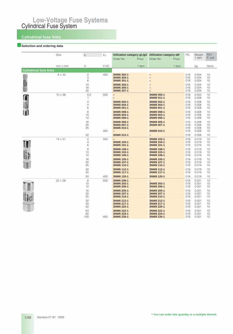
Cylindrical fuse links
1/48
Cylindrical Fuse SystemLow-Voltage Fuse Systems
Siemens ET B1 · 2005
Low-Voltage Fuse Systems
■ Selection and ordering data
Size In Un Utilization category gL/gG Utilization category aM PG Weight PS*/P. unitOrder No. Price Order No. Price 1 item
mm × mm A V AC 1 item 1 item kg Items
Cylindrical fuse links8 × 32 2 400 3NW6 302-1 – 018 0.004 10
4 3NW6 304-1 – 018 0.004 106 3NW6 301-1 – 018 0.004 10
10 3NW6 303-1 – 018 0.004 1016 3NW6 305-1 – 018 0.004 1020 3NW6 307-1 – 018 0.004 10
10 × 38 0.5 500 – 3NW8 000-1 018 0.003 101 – 3NW8 011-1 018 0.008 10
2 3NW6 002-1 3NW8 002-1 018 0.008 104 3NW6 004-1 3NW8 004-1 018 0.008 106 3NW6 001-1 3NW8 001-1 018 0.008 10
8 3NW6 008-1 3NW8 008-1 018 0.008 1010 3NW6 003-1 3NW8 003-1 018 0.008 1012 3NW6 006-1 3NW8 006-1 018 0.008 10
16 3NW6 005-1 3NW8 005-1 018 0.008 1020 3NW6 007-1 3NW8 007-1 018 0.008 1025 3NW6 010-1 018 0.008 10
400 – 3NW8 010-1 018 0.008 10
32 3NW6 012-1 – 018 0.008 10
14 × 51 2 500 – 3NW8 102-1 018 0.019 104 3NW6 104-1 3NW8 104-1 018 0.019 106 3NW6 101-1 3NW8 101-1 018 0.019 10
8 3NW6 108-1 3NW8 108-1 018 0.019 1010 3NW6 103-1 3NW8 103-1 018 0.019 1012 3NW6 106-1 3NW8 106-1 018 0.019 10
16 3NW6 105-1 3NW8 105-1 018 0.019 1020 3NW6 107-1 3NW8 107-1 018 0.019 1025 3NW6 110-1 3NW8 110-1 018 0.019 10
32 3NW6 112-1 3NW8 112-1 018 0.019 1040 3NW6 117-1 3NW8 117-1 018 0.019 10
50 400 3NW6 120-1 3NW8 120-1 018 0.019 10
22 × 58 8 500 3NW6 208-1 – 018 0.051 1010 3NW6 203-1 3NW8 203-1 018 0.051 1012 3NW6 206-1 3NW8 206-1 018 0.051 10
16 3NW6 205-1 3NW8 205-1 018 0.051 1020 3NW6 207-1 3NW8 207-1 018 0.051 1025 3NW6 210-1 3NW8 210-1 018 0.051 10
32 3NW6 212-1 3NW8 212-1 018 0.051 1040 3NW6 217-1 3NW8 217-1 018 0.051 1050 3NW6 220-1 3NW8 220-1 018 0.051 10
63 3NW6 222-1 3NW8 222-1 018 0.051 1080 3NW6 224-1 3NW8 224-1 018 0.051 10
100 400 3NW6 230-1 3NW8 230-1 018 0.051 10
* You can order this quantity or a multiple thereof.
bet_01_07a.fm Seite 48 Mittwoch, 16. Februar 2005 9:32 09

Cylindrical fuse links SITOR
1/49
Cylindrical Fuse SystemLow-Voltage Fuse Systems 1
345678910
1213
Siemens ET B1 · 2005
Low-Voltage Fuse Systems
■ Selection and ordering data
■ Accessories
1) The cylindrical fuse bases can be modularly expanded to make multi-pole bases.
Size In Un Utilization category
Order No. Price PG Weight PS*/P. unit1 item
mm × mm A V AC/V DC 1 item kg Items
Cylindrical fuse links10 × 38 3 600/– aR 3NC1 003 131 0.009 10
6 3NC1 006 131 0.009 108 3NC1 008 131 0.009 10
10 3NC1 010 131 0.009 1012 3NC1 012 131 0.009 1016 3NC1 016 131 0.009 10
20 3NC1 020 131 0.009 1025 3NC1 025 131 0.009 1032 3NC1 032 131 0.009 10
14 × 51 1 660/700 aR 3NC1 401 131 0.020 102 3NC1 402 131 0.020 103 3NC1 403 131 0.020 104 3NC1 404 131 0.020 10
5 690/700 3NC1 405 131 0.020 106 3NC1 406 131 0.020 10
10 3NC1 410 131 0.020 1015 3NC1 415 131 0.020 1020 3NC1 420 131 0.020 10
25 3NC1 425 131 0.020 10
30 3NC1 430 131 0.020 1032 3NC1 432 131 0.021 10
40 3NC1 440 131 0.021 1050 3NC1 450 131 0.021 10
22 × 58 20 690/700 aR 3NC2 220 131 0.056 525 3NC2 225 131 0.056 532 3NC2 232 131 0.056 5
40 3NC2 240 131 0.056 550 3NC2 250 131 0.056 5
63 3NC2 263 131 0.056 580 3NC2 280 131 0.057 5
100 600/700 3NC2 200 131 0.057 5
for cylindrical fuse links Version Order No. Price PG Weight PS*/P. unit1 item
1 item kg Items
Fuse tongs3NC1, 3NC2 3NC1 000 131 0.069 1
Cylindrical fuse switch disconnectors3NC1 0 1-pole 3NC1 091 131 0.065 12
2-pole 3NC1 092 131 0.131 63-pole 3NC1 093 131 0.197 4
3NC1 4 1-pole 3NC1 491 131 0.125 62-pole 3NC1 492 131 0.233 33-pole 3NC1 493 131 0.350 2
3NC2 2 1-pole 3NC2 291 131 0.193 62-pole 3NC2 292 131 0.381 33-pole 3NC2 293 131 0.584 2
Cylindrical fuse base3NC1 0 1-pole 3NC1 038-1 131 0.042 10
2-pole 3NC1 038-2 131 0.077 83-pole 3NC1 038-3 131 0.113 6
3NC1 4 1-pole 1) 3NC1 451-1 131 0.120 3
3NC2 2 1-pole 1) 3NC2 258-1 131 0.238 3
* You can order this quantity or a multiple thereof.
bet_01_07b.fm Seite 49 Mittwoch, 16. Februar 2005 9:33 09

Bases for cylindrical fuses
1/50
Cylindrical Fuse SystemLow-Voltage Fuse Systems
Siemens ET B1 · 2005
Low-Voltage Fuse Systems
■ Selection and ordering data
In for fuse links MW Order No. Price PG Weight PS*/P. unitSize 1 item
A mm x mm 1 item kg Items
Draw-out typewithout signal detector
1-pole20 8 x 32 1 3NW7 310 018 0.058 132 10 x 38 1 3NW7 011 018 0.080 150 14 x 51 1.5 3NW7 111 018 0.095 1
100 22 x 58 2 3NW7 211 018 0.145 1
1-pole + N20 8 x 32 2 3NW7 350 018 0.120 132 10 x 38 2 3NW7 051 018 0.167 150 14 x 51 3 3NW7 151 018 0.215 1
100 22 x 58 4 3NW7 251 018 0.330 1
2-pole20 8 x 32 2 3NW7 320 018 0.112 132 10 x 38 2 3NW7 021 018 0.162 150 14 x 51 3 3NW7 121 018 0.195 1
100 22 x 58 4 3NW7 221 018 0.300 1
3-pole20 8 x 32 3 3NW7 330 018 0.167 132 10 x 38 3 3NW7 031 018 0.243 150 14 x 51 4.5 3NW7 131 018 0.295 1
100 22 x 58 6 3NW7 231 018 0.691 1
3-pole + N20 8 x 32 4 3NW7 360 018 0.227 132 10 x 38 4 3NW7 061 018 0.327 150 14 x 51 6 3NW7 161 018 0.315 1
100 22 x 58 8 3NW7 261 018 0.475 1
with signal detector
1-pole20 8 x 32 1 3NW7 312 018 0.058 132 10 x 38 1 3NW7 012 018 0.080 150 14 x 51 1.5 3NW7 112 018 0.095 1
100 22 x 58 2 3NW7 212 018 0.145 1
1-pole + N20 8 x 32 2 3NW7 352 018 0.120 132 10 x 38 2 3NW7 052 018 0.167 150 14 x 51 3 3NW7 152 018 0.215 1
100 22 x 58 4 3NW7 252 018 0.330 1
2-pole20 8 x 32 2 3NW7 322 018 0.112 132 10 x 38 2 3NW7 022 018 0.162 150 14 x 51 3 3NW7 122 018 0.195 1
100 22 x 58 4 3NW7 222 018 0.300 1
3-pole20 8 x 32 3 3NW7 332 018 0.167 132 10 x 38 3 3NW7 032 018 0.243 150 14 x 51 4.5 3NW7 132 018 0.295 1
100 22 x 58 6 3NW7 232 018 0.480 1
3-pole + N20 8 x 32 4 3NW7 362 018 0.227 132 10 x 38 4 3NW7 062 018 0.327 150 14 x 51 6 3NW7 162 018 0.315 1
100 22 x 58 8 3NW7 262 018 0.475 1
Auxiliary switch
for indicating disconnection of the fuse linkSolely for application of Striker fuse links(not currently available in the Siemens manufacturing program)for retrofitting with factory-fitted brackets, 0.5 MWContact: 250 V AC, 5 A, Minimum contact load: 12 V, 25 mA
for fuse bases 14 x 51 0.5 3NW7 901 018 0.050 1for fuse bases 22 x 58 3NW7 902 018 0.050 1
�
�
�
�
�
�
�
�
�
�
�
�
�
�
�
�
�
�
�
�
�
�
�
�
�
�
�
�
�
�
�
�
�
�
�
�
�
�
�
�
�
�
�
�
�
�
�
�
* You can order this quantity or a multiple thereof.
bet_01_07c.fm Seite 50 Mittwoch, 16. Februar 2005 9:33 09
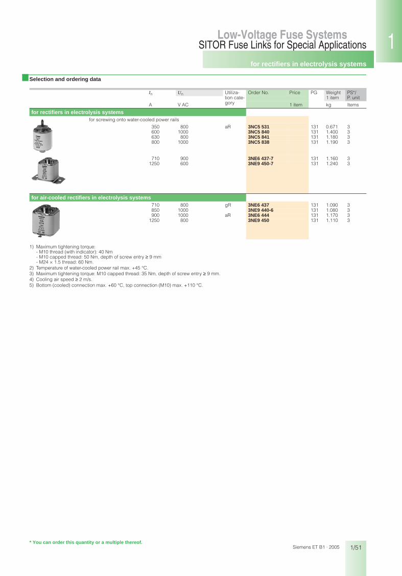
for rectifiers in electrolysis systems
1/51
SITOR Fuse Links for Special ApplicationsLow-Voltage Fuse Systems 1
345678910
1213
Siemens ET B1 · 2005
Low-Voltage Fuse Systems
■ Selection and ordering data
1) Maximum tightening torque: - M10 thread (with indicator): 40 Nm - M10 capped thread: 50 Nm, depth of screw entry ≥ 9 mm- M24 × 1.5 thread: 60 Nm.
2) Temperature of water-cooled power rail max. +45 °C.3) Maximum tightening torque: M10 capped thread: 35 Nm, depth of screw entry ≥ 9 mm.4) Cooling air speed ≥ 2 m/s.5) Bottom (cooled) connection max. +60 °C, top connection (M10) max. +110 °C.
In Un Utiliza-tion cate-gory
Order No. Price PG Weight PS*/P. unit1 item
A V AC 1 item kg Items
for rectifiers in electrolysis systemsfor screwing onto water-cooled power rails
350 800 aR 3NC5 531 131 0.671 3600 1000 3NC5 840 131 1.400 3630 800 3NC5 841 131 1.180 3800 1000 3NC5 838 131 1.190 3
710 900 3NE6 437-7 131 1.160 31250 600 3NE9 450-7 131 1.240 3
for air-cooled rectifiers in electrolysis systems710 800 gR 3NE6 437 131 1.090 3850 1000 3NE9 440-6 131 1.080 3900 1000 aR 3NE6 444 131 1.170 3
1250 800 3NE9 450 131 1.110 3
* You can order this quantity or a multiple thereof.
bet_01_08.fm Seite 51 Mittwoch, 16. Februar 2005 9:33 09

for SITOR thyristor sets
1/52
SITOR Fuse Links for Special ApplicationsLow-Voltage Fuse Systems
Siemens ET B1 · 2005* You can order this quantity or a multiple thereof.
■ Selection and ordering data
1) Maximum tightening torque: M10 capped thread: 35 Nm, depth of screw entry ≥ 9 mm.2) Cooling air speed 0.5 m/s. In case of natural air cooling, reduction of 5%.
■ Selection and ordering data
In Un Utiliza-tion cate-gory
Order No. Price PG Weight PS*/P. unit1 item
A V AC 1 item kg Items
for SITOR 6QG10 thyristor sets 200 1000 aR 3NE3 525-5 131 0.744 3450 3NE3 535-5 131 0.746 3
for SITOR 6QG11 thyristor sets 50 1000 gR 3NE4 117-5 131 0.303 1/3
100 aR 3NE4 121-5 131 0.309 1/3170 800 3NE4 146-5 131 0.311 1/3
for SITOR 6QG12 thyristor sets 250 800 aR 3NE4 327-6B 131 0.692 3315 3NE4 330-6B 131 0.688 3450 3NE4 333-6B 131 0.690 3
500 3NE4 334-6B 131 0.688 3710 3NE4 337-6 131 0.689 3
for railway supply rectifier
In Un Utiliza-tion cate-gory
Order No. Price PG Weight PS*/P. unit1 item
A V AC 1 item kg Items
for railway supply rectifiers250 680 aR 3NC7 327-2 131 0.725 3350 3NC7 331-2 131 0.740 3
7
bet_01_08.fm Seite 52 Mittwoch, 16. Februar 2005 9:33 09