low voltage switchgear - saelzer.com · iec 60947 iec 60204-1 en 60947 en 60204-1 cul 508 1 2 3 2 1...
TRANSCRIPT
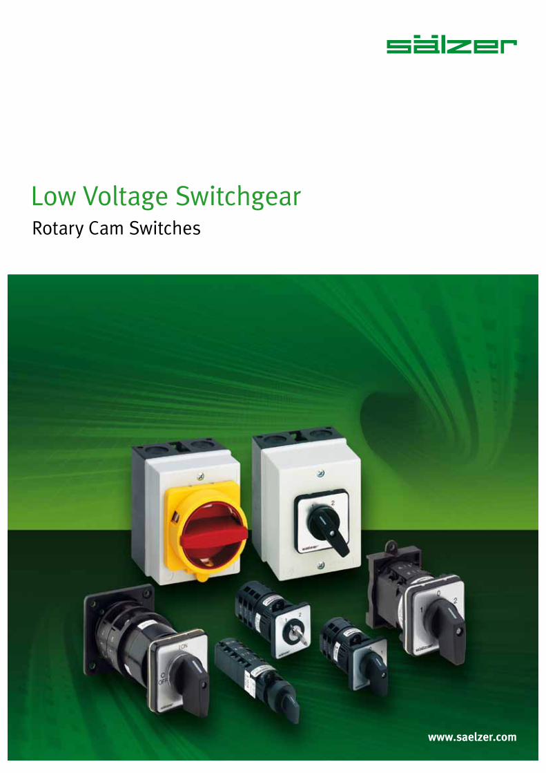
Low Voltage SwitchgearRotary Cam Switches
www.saelzer.com

Innovation. Technology. Quality.
Switchgear from Sälzer: Solutions for the future!Since 1956 Sälzer has specialised in the development, manufacture and sale of low voltage switchgear.
The large selection of types, switching programmes and mounting forms mean that practical reliable solutions can be achieved quickly. Whatever the switch, all individual parts are optimally co-ordinated, easy to assemble and combine. Whether in switching and automation systems, mechanical engineering and construction, in the heating, climatic and ventilation industry, environmental technology or other areas: Sälzer switches provide safety!Product support, training and service as well as a Certifi ed Quality Management to DIN EN ISO 9001 are an essential part of our daily work. Our switches comply with national and international standards (IEC / cUL) and are suitable for world-wide application.
Special requirements?
Call us, we’ll help you fi nd an individual solution for your switching needs. Our Project Engineers are here to understand the special requirements of your project and assist to develop a solution as a partner.Should your requirements not be covered by our extensive standard product range we have our own Design and Development Department for special switches in order to fl exibly, promptly and cost effectively meet your individual requirements.
NS_engl.indb 2NS_engl.indb 2 14.09.2017 08:57:0014.09.2017 08:57:00

Rotary Cam Switches as of p.6
Safe Switching and Controlling
SMD – Sälzer Modular DesignFaster delivery by SMD!
The SMD (Sälzer Modular Design) is based on a modular product idea so that very high fl exibility in productoptions is possible.SMD modules are individually prefabricated and tested complete modules. By combining these basic elements, different switch confi gurations can be realised within short time spans. The switches required by you, the customer, are available for despatch following the assembly of the basic switch module to the mounting form and operator modules (SMD Service). Within 24 hours, the solution matched to your requirements is ready for despatch – worldwide.
NS_engl.indb 3NS_engl.indb 3 14.09.2017 08:57:0114.09.2017 08:57:01
www.saelzer.com4
Page
Rotary Cam Switches 6
Product overview, mounting options 8
Setup of order code number 9
Front mounting 10
Two hole mounting 20 mm 10
Four hole mounting 36 × 36 mm 12
Four hole mounting 48 × 48 mm 15
Four hole mounting 68 × 68 mm 16
Four hole mounting 104 × 104 mm 17
Single hole mounting ∅ 16 mm/22.5 mm 18
Single hole mounting ∅ 22.5 mm 22
Flush wall mounting 27
Base mounting 28
Snap-on mounting 28
Snap-on mounting for DIN rail 29
Snap-on mounting Door clutch with modular shaft extension 30
Snap-on mounting Door interlock with modular shaft extension 32
Four hole mounting 68 × 68 mm 34
Four hole mounting 68 × 68 mm / door clutch 36
Four hole mounting 68 × 68 mm / door interlock 38
Four hole mounting 104 × 104 mm 40
Four hole mounting 104 × 104 mm / door clutch 41
Four hole mounting 104 × 104 mm / door interlock 42
Table of Contents
NS_engl.indb 4NS_engl.indb 4 14.09.2017 08:57:0114.09.2017 08:57:01
5
Table of Contents
Page
Enclosed switches 43
Insulated enclosure 68 × 68 × 53 mm 43
Insulated enclosure 100 × 80 × 65 mm 45
Insulated enclosure 100 × 80 × 85 mm 48
Insulated enclosure 125 × 100 × 133 mm 52
Technical information 56
Switching programmes 56
Switching diagrams 66
Legend plates 76
Accessories 83
Key removable positions 85
Operator variants 86
How to order special switches / Copy form for special switches 88
How to order special engravings / Copy form for special engravings 90
Utilisation categories 92
Rated currents of three-phase motors 93
Degree of protection 94
Mounting form table 95
Technical data 96
Contacts 98
NS_engl.indb 5NS_engl.indb 5 14.09.2017 08:57:0214.09.2017 08:57:02

www.saelzer.com6
NS_engl.indb 6NS_engl.indb 6 14.09.2017 08:57:0214.09.2017 08:57:02

7
Rotary Cam SwitchesSafe Switching and Controlling
Rotary Cam Switches from Sälzer Electric are independently programmable, manually operated control switches for main and auxiliary circuits with up to 24 contacts and are offered with switching angles of 30°, 45°, 60° or 90°. Therefore a maximum of 12 switching positions can be provided.
Design and Function
30°, 45°, 60° or 90° switching angle
forced open contacts fi nger protected
(degree of protection up to IP20) short-circuit rating fulfi lls the load break requirements
up to 480 V terminal screws in open position
Applications
Rotary Cam Switches offer ideal features for their use as:
ON-OFF Switches Changeover Switches Multi-step Switches Code Switches Gang Switches Instrument Switches Motor Switches
Conformity
Our products are designed, manu-factured and tested according to the following standards:
IEC 60947 IEC 60204-1 EN 60947 EN 60204-1 cUL 508
1
2
3
2
1 Operator module2 Mounting form module3 Switch module
NS_engl.indb 7NS_engl.indb 7 14.09.2017 08:57:0314.09.2017 08:57:03

www.saelzer.com8
Mounting options:
Our modular technology allows us to build custom switching solutionsfor up to 24 poles!
Rotary Cam Switches
Product overview
Front mounting
Two hole mounting Four hole mounting Single hole mounting Flush wall mounting
Base mounting
Snap-on mounting (DIN rail 35 mm DIN EN 60715)
Four hole mounting
Enclosed switches
Insulated enclosure
NS_engl.indb 8NS_engl.indb 8 14.09.2017 08:57:0414.09.2017 08:57:04
9
Rotary Cam Switches
Setup of order code number
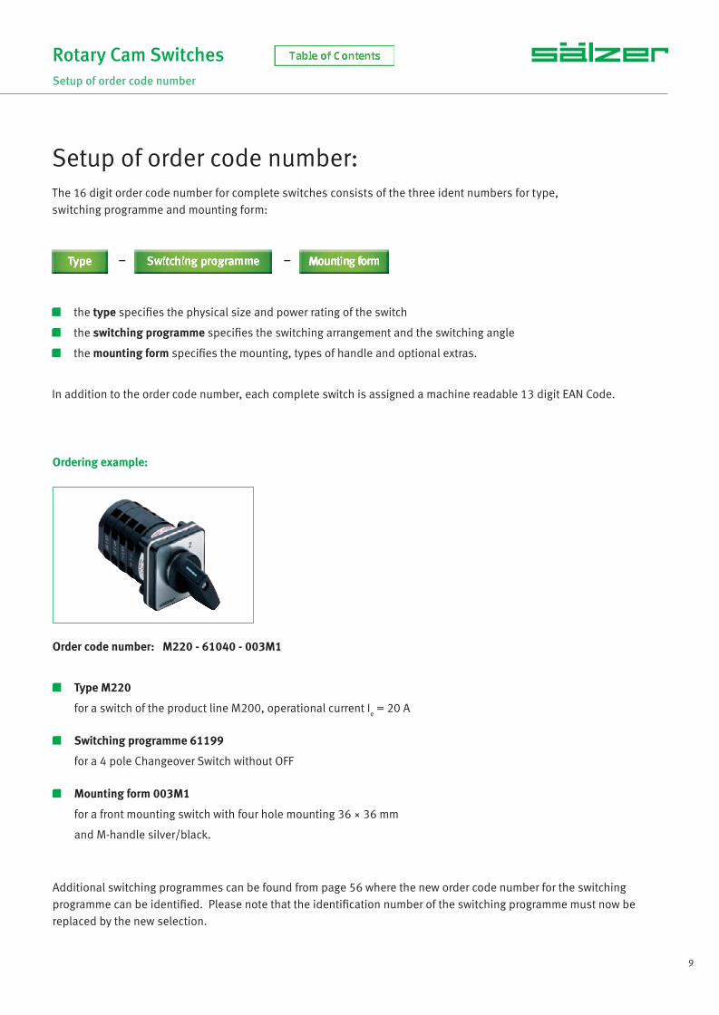
Ordering example:
Order code number: M220 - 61040 - 003M1
Type M220
for a switch of the product line M200, operational current Ie = 20 A
Switching programme 61199
for a 4 pole Changeover Switch without OFF
Mounting form 003M1
for a front mounting switch with four hole mounting 36 × 36 mm
and M-handle silver/black.
Additional switching programmes can be found from page 56 where the new order code number for the switching programme can be identifi ed. Please note that the identifi cation number of the switching programme must now be replaced by the new selection.
The 16 digit order code number for complete switches consists of the three ident numbers for type, switching programme and mounting form:
the type specifi es the physical size and power rating of the switch
the switching programme specifi es the switching arrangement and the switching angle
the mounting form specifi es the mounting, types of handle and optional extras.
In addition to the order code number, each complete switch is assigned a machine readable 13 digit EAN Code.
– –
Setup of order code number:
NS_engl.indb 9NS_engl.indb 9 14.09.2017 08:57:0714.09.2017 08:57:07

10 www.saelzer.com
• Control Switch • Instrument Switch• ON-OFF Switch • Changeover Switch• Multi-step Switch • Motor Switch
Front mounting switches with two hole mounting 20 mm
10 A 1 up to 16 contacts IP66 (front)
Type Rated data (IEC 60947) Degree of Protection Terminal accessibility
Operational current I
e
Operational power (at 380–440 V) Terminals
AC-21A (A) AC-23A (kW) AC-3A (kW)
P110 10 3 2.2 IP20 Terminals accessible frommounting direction
Rotary Cam SwitchesFront mounting Two hole mounting 20 mm
Switching diagrams and further switching programmes from page 56.
Switching programme Stages Contacts Description
61191 1 1 ON-OFF Switch 90°, 1 pole
61192 1 2 ON-OFF Switch 90°, 2 pole
61001 1 1 ON-OFF Switch 60°, 1 pole
61002 1 2 ON-OFF Switch 60°, 2 pole
61351 1 1 ON-OFF Switch with spring return, 1 pole
61025 1 2 Changeover Switch with centre OFF 60°, 1 pole
61026 2 4 Changeover Switch with centre OFF 60°, 2 pole
61037 1 2 Changeover Switch without OFF 60°, 1 pole
61049 2 3 Multi-step Switch without OFF, 3 steps, 1 pole
61050 2 4 Multi-step Switch without OFF, 4 steps, 1 pole
61070 4 8 Multi-step Switch without OFF, 4 steps, 1 pole
61109 1 2 Gang Switch, 2 gangs, 1 pole
61111 3 6 Gang Switch, 2 gangs, 3 pole
Mounting form Operator
003M1 M-handle silver/black
Dimensions in mm:
L with … stages (max. 8)Type A C1 D D1 D2 E 1 2 3 4 5 6 7 8
P110 30 24 29 8 3.2 20 39 51 63 75 87 99 111 123
Setup of order code number: Type - Switching programme - Mounting formOrdering example:2 pole Multi-Step Switch without OFF, 10 A, M-handle silver/black
Type Switching programme Mtg. form
P110 61070 003M1
Order code no. P110-61070-003M1
NS_engl.indb 10NS_engl.indb 10 14.09.2017 08:57:0714.09.2017 08:57:07

11
Front mounting switches with two hole mounting 20 mm
10 A 1 up to 16 contacts IP66 (front)
Type Rated data (IEC 60947) Degree of Protection Terminal accessibility
Operational current I
e
Operational power (at 380–440 V) Terminals
AC-21A (A) AC-23A (kW) AC-3A (kW)
P110 10 3 2.2 IP20 Terminals accessible frommounting direction
Rotary Cam SwitchesFront mounting Two hole mounting 20 mm
Switching diagrams and further switching programmes from page 56.
Switching programme Stages Contacts Description
61191 1 1 ON-OFF Switch 90°, 1 pole
61192 1 2 ON-OFF Switch 90°, 2 pole
61199 2 3 ON-OFF Switch 90°, 3 pole
61194 2 4 ON-OFF Switch 90°, 4 pole, 1 pole early make/late break
61906 3 6 ON-OFF Switch 90°, 6 pole
61919 4 8 ON-OFF Switch 90°, 8 pole, 2 pole early make/late break
Dimensions in mm:
L with … stages (max. 8)Type A C1 D D1 D2 E 1 2 3 4 5 6 7 8
P110 48 31 29 8 3.2 20 39 51 63 75 87 99 111 123
Setup of order code number: Type - Switching programme - Mounting formOrdering example:1 pole Main/Emergency-Off Switch 90°, 10 A, padlock device with M-handle yellow/red
Type Switching programme Mtg. form
P110 61191 033M4
Order code no. P110-61191-033M4
• Main/Emergency-Off Switch• Main Switch
Mounting form Operator Main/Emergency-Off Switch Mounting form Operator Main Switch
033M4 padlock device with M-handleyellow/red 033M1
padlock device with M-handleblack
NS_engl.indb 11NS_engl.indb 11 14.09.2017 08:57:0714.09.2017 08:57:07
12 www.saelzer.com
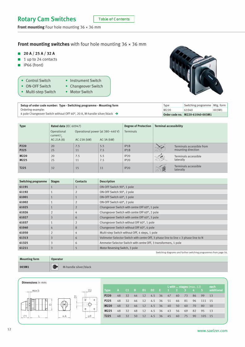
Rotary Cam SwitchesFront mounting Four hole mounting 36 × 36 mm
Switching diagrams and further switching programmes from page 56.
Switching programme Stages Contacts Description
61191 1 1 ON-OFF Switch 90°, 1 pole
61192 1 2 ON-OFF Switch 90°, 2 pole
61001 1 1 ON-OFF Switch 60°, 1 pole
61002 1 2 ON-OFF Switch 60°, 2 pole
61025 1 2 Changeover Switch with centre OFF 60°, 1 pole
61026 2 4 Changeover Switch with centre OFF 60°, 2 pole
61027 3 6 Changeover Switch with centre OFF 60°, 3 pole
61037 1 2 Changeover Switch without OFF 60°, 1 pole
61040 4 8 Changeover Switch without OFF 60°, 4 pole
61050 2 4 Multi-step Switch without OFF, 4 steps, 1 pole
61313 3 6 Voltmeter Selector Switch with centre OFF, 3 phase line to line + 3 phase line to N
61325 3 6 Ammeter Selector Switch with centre OFF, 3 transformers, 1 pole
61211 3 5 Motor Reversing Switch, 3 pole
Mounting form Operator
003M1 M-handle silver/black
Dimensions in mm:
Setup of order code number: Type - Switching programme - Mounting formOrdering example:4 pole Changeover Switch without OFF 60°, 20 A, M-handle silver/black
Type Switching programme Mtg. form
M220 61040 003M1
Order code no. M220-61040-003M1
Front mounting switches with four hole mounting 36 × 36 mm
20 A / 25 A / 32 A 1 up to 24 contacts IP66 (front)
Type Rated data (IEC 60947) Degree of Protection Terminal accessibility
Operational current I
e
Operational power (at 380–440 V) Terminals
AC-21A (A) AC-23A (kW) AC-3A (kW)
P220P225
2025
7.511
5.57.5
IP1BIP1B
Terminals accessible frommounting direction
M220M225
2025
7.511
5.57.5
IP20IP20
Terminals accessiblelaterally
T225 32 15 11 IP20 Terminals accessiblelaterally
L with … stages (max. 12) eachType A C1 D D1 D2 E 1 2 3 4 5 additional
P220 48 32 44 12 4.5 36 47 60 73 86 99 13
P225 48 32 46 12 4.5 36 51 66 81 96 111 15
M220 48 32 46 12 4.5 36 40 50 60 70 80 10
M225 48 32 48 12 4.5 36 43 56 69 82 95 13
T225 48 32 50 12 4.5 36 45 60 75 90 105 15
• Control Switch • Instrument Switch• ON-OFF Switch • Changeover Switch• Multi-step Switch • Motor Switch
NS_engl.indb 12NS_engl.indb 12 14.09.2017 08:57:0714.09.2017 08:57:07

13
Rotary Cam SwitchesFront mounting Four hole mounting 36 × 36 mm
Switching diagrams and further switching programmes from page 56.
Switching programme Stages Contacts Description
61191 1 1 ON-OFF Switch 90°, 1 pole
61192 1 2 ON-OFF Switch 90°, 2 pole
61199 2 3 ON-OFF Switch 90°, 3 pole
61194 2 4 ON-OFF Switch 90°, 4 pole, 1 pole early make/late break
61001 1 1 ON-OFF Switch 60°, 1 pole
61002 1 2 ON-OFF Switch 60°, 2 pole
61003 2 3 ON-OFF Switch 60°, 3 pole
61025 1 2 Changeover Switch with centre OFF 60°, 1 pole
61027 3 6 Changeover Switch with centre OFF 60°, 3 pole
61362 2 4 Changeover Switch with centre OFF and spring return 60°, 2 pole
61037 1 2 Changeover Switch without OFF 60°, 1 pole
61049 2 3 Multi-step Switch without OFF, 3 steps, 1 pole
61050 2 4 Multi-step Switch without OFF, 4 steps, 1 pole
Mounting form Operator
005M1 M-handle silver/black
Dimensions in mm:
Setup of order code number: Type - Switching programme - Mounting formOrdering example:2 pole Changeover Switch with centre OFF and spring return 60°, 20 A, M-handle silver/black
Type Switching programme Mtg. form
M220 61362 005M1
Order code no. M220-61362M005M1
Front mounting switches with four hole mounting 36 × 36 mm
with dust protective cover 20 A / 25 A / 32 A 1 up to max. 8 contacts IP66
Type Contacts Rated data (IEC 60947) Degree of Protection Terminal accessibility
Operational current I
e
Operational power (at 380–440 V) Terminals
AC-21A (A) AC-23A (kW) AC-3A (kW)
P220P225
1 to 61 to 4
2025
7.511
5.57.5
IP66IP66
Terminals accessible frommounting direction
M220M225
1 to 81 to 6
2025
7.511
5.57.5
IP66IP66
Terminals accessiblelaterally
T225 1 to 4 32 15 11 IP66 Terminals accessiblelaterally
L with … stagesType A B C1 D1 D2 E H 1 2 3 4
P220 48 64 32 12 4.5 36 88 80 80 80 -
P225 48 64 32 12 4.5 36 88 80 80 - -
M220 48 64 32 12 4.5 36 88 80 80 80 80
M225 48 64 32 12 4.5 36 88 80 80 80 -
T225 48 88 32 12 4.5 36 64 80 80 - -
M200/P200 T225
• Control Switch • Instrument Switch• ON-OFF Switch • Changeover Switch• Multi-step Switch • Motor Switch
NS_engl.indb 13NS_engl.indb 13 14.09.2017 08:57:0814.09.2017 08:57:08

14 www.saelzer.com
Front mounting switches with four hole mounting 36 × 36 mm
20 A / 25 A / 32 A 1 up to 24 contacts IP66 (front)
Type Rated data (IEC 60947) Degree of Protection Terminal accessibility
Operational current I
e
Operational power (at 380–440 V) Terminals
AC-21A (A) AC-23A (kW) AC-3A (kW)
P220P225
2025
7.511
5.57.5
IP1BIP1B
Terminals accessible frommounting direction
M220M225
2025
7.511
5.57.5
IP20IP20
Terminals accessiblelaterally
T225 32 15 11 IP20 Terminals accessiblelaterally
Rotary Cam SwitchesFront mounting Four hole mounting 36 × 36 mm
Switching diagrams and further switching programmes from page 56.
Setup of order code number: Type - Switching programme - Mounting formOrdering example:2 pole Main/Emergency-Off Switch 90°, 20 A, padlock device with M-handle yellow/red
Type Switching programme Mtg. form
M220 61192 033M4
Order code no. M220-61192-033M4
Switching programme Stages Contacts Description
61191 1 1 ON-OFF Switch 90°, 1 pole
61192 1 2 ON-OFF Switch 90°, 2 pole
61199 2 3 ON-OFF Switch 90°, 3 pole
61194 2 4 ON-OFF Switch 90°, 4 pole, 1 pole early make/late break
61906 3 6 ON-OFF Switch 90°, 6 pole
61919 4 8 ON-OFF Switch 90°, 8 pole, 2 pole early make/late break
Mounting form Operator Main/Emergency-Off Switch Mounting form Operator Main Switch
033N4 padlock device with N-handleyellow/red 033N1
padlock device with N-handleblack
033M4 padlock device with M-handleyellow/red 033M1
padlock device with M-handleblack
033V4 padlockable with V-handleyellow/red 033V1
padlockable with V-handlesilver/black
• Main/Emergency-Off Switch• Main Switch
L with … stages (max. 12) eachType Mounting form A C1 D D1 D2 E 1 2 3 4 5 additional
P220 033N4/033N1 67 33 44 15 4.5 36 47 60 73 86 99 13033M4/033M1 67 38 44 15 4.5 36 47 60 73 86 99 13033V4/033V1 48 32 44 12 4.5 36 47 60 73 86 99 13
P225 033N4/033N1 67 33 46 15 4.5 36 51 66 81 96 111 15033M4/033M1 67 38 46 15 4.5 36 51 66 81 96 111 15033V4/033V1 48 32 46 12 4.5 36 51 66 81 96 111 15
M220 033N4/033N1 67 33 46 15 4.5 36 40 50 60 70 80 10033M4/033M1 67 38 46 15 4.5 36 40 50 60 70 80 10033V4/033V1 48 32 46 12 4.5 36 40 50 60 70 80 10
M225 033N4/033N1 67 33 48 15 4.5 36 43 56 69 82 95 13033M4/033M1 67 38 48 15 4.5 36 43 56 69 82 95 13033V4/033V1 48 32 48 12 4.5 36 43 56 69 82 95 13
T225 033N4/033N1 67 33 50 15 4.5 36 45 60 75 90 105 15033M4/033M1 67 38 50 15 4.5 36 45 60 75 90 105 15
033V4/033V1 48 32 50 12 4.5 36 45 60 75 90 105 15
Dimensions in mm:
NS_engl.indb 14NS_engl.indb 14 14.09.2017 08:57:0814.09.2017 08:57:08
15
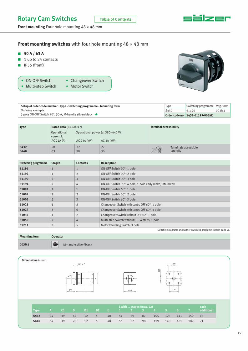
• ON-OFF Switch • Changeover Switch• Multi-step Switch • Motor Switch
Front mounting switches with four hole mounting 48 × 48 mm
50 A / 63 A 1 up to 24 contacts IP55 (front)
Type Rated data (IEC 60947) Terminal accessibility
Operational current I
e
Operational power (at 380–440 V)
AC-21A (A) AC-23A (kW) AC-3A (kW)
S432S440
5063
2230
2230
Terminals accessiblelaterally
Rotary Cam SwitchesFront mounting Four hole mounting 48 × 48 mm
Switching diagrams and further switching programmes from page 56.
Switching programme Stages Contacts Description
61191 1 1 ON-OFF Switch 90°, 1 pole
61192 1 2 ON-OFF Switch 90°, 2 pole
61199 2 3 ON-OFF Switch 90°, 3 pole
61194 2 4 ON-OFF Switch 90°, 4 pole, 1 pole early make/late break
61001 1 1 ON-OFF Switch 60°, 1 pole
61002 1 2 ON-OFF Switch 60°, 2 pole
61003 2 3 ON-OFF Switch 60°, 3 pole
61025 1 2 Changeover Switch with centre OFF 60°, 1 pole
61027 3 6 Changeover Switch with centre OFF 60°, 3 pole
61037 1 2 Changeover Switch without OFF 60°, 1 pole
61050 2 4 Multi-step Switch without OFF, 4 steps, 1 pole
61211 3 5 Motor Reversing Switch, 3 pole
Mounting form Operator
003M1 M-handle silver/black
Dimensions in mm:
L with … stages (max. 12) eachType A C1 D D1 D2 E 1 2 3 4 5 6 7 additional
S432 64 39 65 12 5 48 51 69 87 105 123 141 159 18
S440 64 39 70 12 5 48 56 77 98 119 140 161 182 21
Setup of order code number: Type - Switching programme - Mounting formOrdering example:3 pole ON-OFF Switch 90°, 50 A, M-handle silver/black
Type Switching programme Mtg. form
S432 61199 003M1
Order code no. S432-61199-003M1
NS_engl.indb 15NS_engl.indb 15 14.09.2017 08:57:0814.09.2017 08:57:08

16 www.saelzer.com
Dimensions in mm:
• ON-OFF Switch • Changeover Switch• Multi-step Switch • Motor Switch
Front mounting switches with four hole mounting 68 × 68 mm
80 A / 100 A / 160 A 1 up to 24 contacts IP55 (front)
Type Rated data (IEC 60947) Terminal accessibility
Operational current I
e
Operational power (at 380–440 V)
AC-21A (A) AC-23A (kW) AC-3A (kW)
S606S608S612
80100160
455575
303745
Terminals accessiblelaterally
Rotary Cam SwitchesFront mounting Four hole mounting 68 × 68 mm
Switching diagrams and further switching programmes from page 56.
Switching programme Stages Contacts Description
61191 1 1 ON-OFF Switch 90°, 1 pole
61192 1 2 ON-OFF Switch 90°, 2 pole
61199 2 3 ON-OFF Switch 90°, 3 pole
61194 2 4 ON-OFF Switch 90°, 4 pole, 1 pole early make/late break
61001 1 1 ON-OFF Switch 60°, 1 pole
61002 1 2 ON-OFF Switch 60°, 2 pole
61003 2 3 ON-OFF Switch 60°, 3 pole
61025 1 2 Changeover Switch with centre OFF 60°, 1 pole
61027 3 6 Changeover Switch with centre OFF 60°, 3 pole
61037 1 2 Changeover Switch without OFF 60°, 1 pole
61050 2 4 Multi-step Switch without OFF, 4 steps, 1 pole
61211 3 5 Motor Reversing Switch, 3 pole
Setup of order code number: Type - Switching programme - Mounting formOrdering example:3 pole ON-OFF Switch 90°, 80 A, G-handle silver/black
Type Switching programme Mtg. form
S606 61199 003G1
Order code no. S606-61199-003G1
L with … stages (max. 12) eachType Mtg. form A C1 D D1 D2 E 1 2 3 4 5 additional
S606 003M1 88 52 84 15 5.5 68 59 81 103 125 147 22
003G1 88 66 84 15 5.5 68 59 81 103 125 147 22
S608 003M1 88 52 88 15 5.5 68 66 92 118 144 170 26
003G1 88 66 88 15 5.5 68 66 92 118 144 170 26
S612 003M1 88 52 88 15 5.5 68 72 104 136 168 200 32
003G1 88 66 88 15 5.5 68 72 104 136 168 200 32
Mounting form Operator Mounting form Operator
003M1 M-handle silver/black 003G1 G-handle silver/black
NS_engl.indb 16NS_engl.indb 16 14.09.2017 08:57:0914.09.2017 08:57:09

17
• ON-OFF Switch • Changeover Switch• Multi-step Switch • Motor Switch
Front mounting switches with four hole mounting 104 × 104 mm
315 A 1 up to 24 contacts IP55 (front)
Type Rated data (IEC 60947) Terminal accessibility
Operational current I
e
Operational power (at 380–440 V)
AC-21A (A) AC-23A (kW) AC-3A (kW)
S825 315 132 55 Terminals accessiblelaterally
Rotary Cam SwitchesFront mounting Four hole mounting 104 × 104 mm
Switching diagrams and further switching programmes from page 56.
Switching programme Stages Contacts Description
61191 1 1 ON-OFF Switch 90°, 1 pole
61192 1 2 ON-OFF Switch 90°, 2 pole
61199 2 3 ON-OFF Switch 90°, 3 pole
61194 2 4 ON-OFF Switch 90°, 4 pole, 1 pole early make/late break
61001 1 1 ON-OFF Switch 60°, 1 pole
61002 1 2 ON-OFF Switch 60°, 2 pole
61003 2 3 ON-OFF Switch 60°, 3 pole
61025 1 2 Changeover Switch with centre OFF 60°, 1 pole
61027 3 6 Changeover Switch with centre OFF 60°, 3 pole
61037 1 2 Changeover Switch without OFF 60°, 1 pole
61050 2 4 Multi-step Switch without OFF, 4 steps, 1 pole
Setup of order code number: Type - Switching programme - Mounting formOrdering example:4 pole ON-OFF Switch 90°, 315 A, G-handle silver/black
Type Switching programme Mtg. form
S825 61194 003G1
Order code no. S825-61194-003G1
Mounting form Operator
003G1 G-handle silver/black
Dimensions in mm:
L with … stages (max. 12) eachType A C1 D DAW D1 D2 E 1 2 3 4 5 6 7 additional
S825 130 74 120 210 20 5.5 104 89 125 161 197 233 269 305 36
NS_engl.indb 17NS_engl.indb 17 14.09.2017 08:57:0914.09.2017 08:57:09

18 www.saelzer.com
• Control Switch • Instrument Switch• ON-OFF Switch • Changeover Switch• Multi-step Switch • Motor Switch
Front mounting switches with single hole mounting Ø 16 mm/22.5 mm
10 A 1 up to 16 contacts IP66 (front)
Type Rated data (IEC 60947) Degree of Protection Terminal accessibility
Operational current I
e
Operational power (at 380–440 V) Terminals
AC-21A (A) AC-23A (kW) AC-3A (kW)
P110 10 3 2.2 IP20 Terminals accessible frommounting direction
Rotary Cam SwitchesFront mounting Single hole mounting ∅ 16 mm/22.5 mm
Switching diagrams and further switching programmes from page 56.
Switching programme Stages Contacts Description
61191 1 1 ON-OFF Switch 90°, 1 pole
61192 1 2 ON-OFF Switch 90°, 2 pole
61001 1 1 ON-OFF Switch 60°, 1 pole
61002 1 2 ON-OFF Switch 60°, 2 pole
61351 1 1 ON-OFF Switch with spring return, 1 pole
61025 1 2 Changeover Switch with centre OFF 60°, 1 pole
61026 2 4 Changeover Switch with centre OFF 60°, 2 pole
61028 4 8 Changeover Switch with centre OFF 60°, 4 pole
61037 1 2 Changeover Switch without OFF 60°, 1 pole
61049 2 3 Multi-step Switch without OFF, 3 steps, 1 pole
61050 2 4 Multi-step Switch without OFF, 4 steps, 1 pole
61109 1 2 Gang Switch, 2 gangs, 1 pole
61111 3 6 Gang Switch, 2 gangs, 3 pole
Mounting form Operator
219M1 M-handle silver/black
Dimensions in mm:
L with … stages (max. 8) eachType A C1 D D1 D2 G1 G2 G3 G4 1 2 3 4 additional
P110 30 26 29 22.5 16.2 20 3.2 17.9 1.7 57 69 81 93 12
Setup of order code number: Type - Switching programme - Mounting formOrdering example:4 pole Changeover Switch with centre OFF 60°, 10 A, M-handle silver/black
Type Switching programme Mtg. form
P110 61028 219M1
Order code no. P110-61028-219M1
NS_engl.indb 18NS_engl.indb 18 14.09.2017 08:57:0914.09.2017 08:57:09

19
• Control Switch • Instrument Switch• ON-OFF Switch • Changeover Switch• Multi-step Switch • Motor Switch
Front mounting switches with single hole mounting Ø 16 mm/22.5 mm
with front ring 10 A 1 up to 16 contacts IP66 (front)
Type Rated data (IEC 60947) Degree of Protection Terminal accessibility
Operational current I
e
Operational power (at 380–440 V) Terminals
AC-21A (A) AC-23A (kW) AC-3A (kW)
P110 10 3 2.2 IP20 Terminals accessible frommounting direction
Rotary Cam SwitchesFront mounting Single hole mounting ∅ 16 mm/22.5 mm
Switching diagrams and further switching programmes from page 56.
Switching programme Stages Contacts Description
61191 1 1 ON-OFF Switch 90°, 1 pole
61192 1 2 ON-OFF Switch 90°, 2 pole
61001 1 1 ON-OFF Switch 60°, 1 pole
61002 1 2 ON-OFF Switch 60°, 2 pole
61351 1 1 ON-OFF Switch with spring return, 1 pole
61025 1 2 Changeover Switch with centre OFF 60°, 1 pole
61026 2 4 Changeover Switch with centre OFF 60°, 2 pole
61028 4 8 Changeover Switch with centre OFF 60°, 4 pole
61037 1 2 Changeover Switch without OFF 60°, 1 pole
61049 2 3 Multi-step Switch without OFF, 3 steps, 1 pole
61050 2 4 Multi-step Switch without OFF, 4 steps, 1 pole
61109 1 2 Gang Switch, 2 gangs, 1 pole
61111 3 6 Gang Switch, 2 gangs, 3 pole
Mounting form Operator
218M1 M-handle with front ring black/black
Dimensions in mm:
L with … stages (max. 8) eachType A C1 D D1 D2 G1 G2 G3 G4 1 2 3 4 additional
P110 30 26 29 22.5 16.2 24.2 3.2 17.9 1.7 57 69 81 93 12
Setup of order code number: Type - Switching programme - Mounting formOrdering example:4 pole Changeover Switch with centre OFF 60°, 10 A, M-handle with front ring black/black
Type Switching programme Mtg. form
P110 61028 218M1
Order code no. P110-61028-218M1
NS_engl.indb 19NS_engl.indb 19 14.09.2017 08:57:1014.09.2017 08:57:10

20 www.saelzer.com
• Control Switch • Instrument Switch• ON-OFF Switch • Changeover Switch• Multi-step Switch • Motor Switch
Front mounting switches with single hole mounting Ø 16 mm/22.5 mm
key operated 10 A 1 up to 16 contacts IP40 (front)
Type Rated data (IEC 60947) Degree of Protection Terminal accessibility
Operational current I
e
Operational power (at 380–440 V) Terminals
AC-21A (A) AC-23A (kW) AC-3A (kW)
P110 10 3 2.2 IP20 Terminals accessible frommounting direction
Rotary Cam SwitchesFront mounting Single hole mounting ∅ 16 mm/22.5 mm
Switching diagrams and further switching programmes from page 56.
Switching programme Stages Contacts Description
61191 1 1 ON-OFF Switch 90°, 1 pole
61192 1 2 ON-OFF Switch 90°, 2 pole
61001 1 1 ON-OFF Switch 60°, 1 pole
61002 1 2 ON-OFF Switch 60°, 2 pole
61351 1 1 ON-OFF Switch with spring return, 1 pole
61025 1 2 Changeover Switch with centre OFF 60°, 1 pole
61026 2 4 Changeover Switch with centre OFF 60°, 2 pole
61037 1 2 Changeover Switch without OFF 60°, 1 pole
61049 2 3 Multi-step Switch without OFF, 3 steps, 1 pole
61050 2 4 Multi-step Switch without OFF, 4 steps, 1 pole
61109 1 2 Gang Switch, 2 gangs, 1 pole
61111 3 6 Gang Switch, 2 gangs, 3 pole
Mounting form Operator
S001. * Key operated, silver/metal keyRonis cylinder lock L001, 2 keys (other lock types on request)
Dimensions in mm:
L with … stages (max. 8) eachType A C1 D D1 D2 G1 G2 G3 G4 1 2 3 4 additional
P110 30 26 29 22.5 16.2 24.2 3.2 17.9 1.7 57 69 81 93 12
Setup of order code number: Type - Switching programme - Mounting formOrdering example:1 pole Multi-step Switch without OFF, 10 A, key operated, key removable at 9h
Type Switching programme Mtg. form
P110 61050 S001A
Order code no. P110-61050-S001A
* The dot in the order code number must be replaced by the classifi cation letter which identifi es the key removable positions, see page 85.
NS_engl.indb 20NS_engl.indb 20 14.09.2017 08:57:1014.09.2017 08:57:10
21
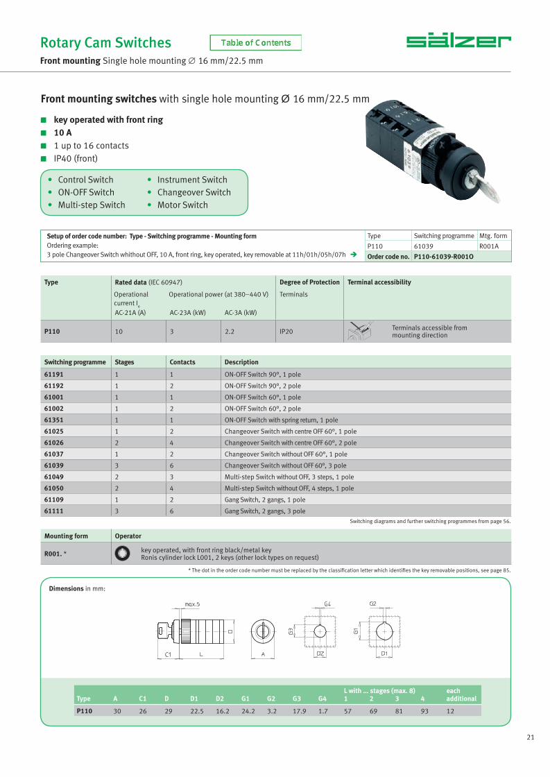
• Control Switch • Instrument Switch• ON-OFF Switch • Changeover Switch• Multi-step Switch • Motor Switch
Front mounting switches with single hole mounting Ø 16 mm/22.5 mm
key operated with front ring 10 A 1 up to 16 contacts IP40 (front)
Type Rated data (IEC 60947) Degree of Protection Terminal accessibility
Operational current I
e
Operational power (at 380–440 V) Terminals
AC-21A (A) AC-23A (kW) AC-3A (kW)
P110 10 3 2.2 IP20 Terminals accessible frommounting direction
Rotary Cam SwitchesFront mounting Single hole mounting ∅ 16 mm/22.5 mm
Switching diagrams and further switching programmes from page 56.
Switching programme Stages Contacts Description
61191 1 1 ON-OFF Switch 90°, 1 pole
61192 1 2 ON-OFF Switch 90°, 2 pole
61001 1 1 ON-OFF Switch 60°, 1 pole
61002 1 2 ON-OFF Switch 60°, 2 pole
61351 1 1 ON-OFF Switch with spring return, 1 pole
61025 1 2 Changeover Switch with centre OFF 60°, 1 pole
61026 2 4 Changeover Switch with centre OFF 60°, 2 pole
61037 1 2 Changeover Switch without OFF 60°, 1 pole
61039 3 6 Changeover Switch without OFF 60°, 3 pole
61049 2 3 Multi-step Switch without OFF, 3 steps, 1 pole
61050 2 4 Multi-step Switch without OFF, 4 steps, 1 pole
61109 1 2 Gang Switch, 2 gangs, 1 pole
61111 3 6 Gang Switch, 2 gangs, 3 pole
Mounting form Operator
R001. * key operated, with front ring black/metal keyRonis cylinder lock L001, 2 keys (other lock types on request)
Dimensions in mm:
L with … stages (max. 8) eachType A C1 D D1 D2 G1 G2 G3 G4 1 2 3 4 additional
P110 30 26 29 22.5 16.2 24.2 3.2 17.9 1.7 57 69 81 93 12
Setup of order code number: Type - Switching programme - Mounting formOrdering example:3 pole Changeover Switch whithout OFF, 10 A, front ring, key operated, key removable at 11h/01h/05h/07h
Type Switching programme Mtg. form
P110 61039 R001A
Order code no. P110-61039-R001O
* The dot in the order code number must be replaced by the classifi cation letter which identifi es the key removable positions, see page 85.
NS_engl.indb 21NS_engl.indb 21 14.09.2017 08:57:1014.09.2017 08:57:10

22 www.saelzer.com
• Control Switch • Instrument Switch• ON-OFF Switch • Changeover Switch• Multi-step Switch • Motor Switch
Rotary Cam SwitchesFront mounting Single hole mounting ∅ 22.5 mm
Switching diagrams and further switching programmes from page 56.
Switching programme Stages Contacts Description
61191 1 1 ON-OFF Switch 90°, 1 pole
61192 1 2 ON-OFF Switch 90°, 2 pole
61001 1 1 ON-OFF Switch 60°, 1 pole
61002 1 2 ON-OFF Switch 60°, 2 pole
61004 2 4 ON-OFF Switch 60°, 4 pole
61025 1 2 Changeover Switch with centre OFF 60°, 1 pole
61026 2 4 Changeover Switch with centre OFF 60°, 2 pole
61027 3 6 Changeover Switch with centre OFF 60°, 3 pole
61037 1 2 Changeover Switch without OFF 60°, 1 pole
61050 2 4 Multi-step Switch without OFF, 4 steps, 1 pole
61313 3 6 Voltmeter Selector Switch with centre OFF, 3 phase line to line + 3 phase line to N
61325 3 6 Ammeter Selector Switch with centre OFF, 3 transformers, 1 pole
61211 3 5 Motor Reversing Switch, 3 pole
Mounting form Operator
219M1 M-handle silver/black
Dimensions in mm:
Setup of order code number: Type - Switching programme - Mounting formOrdering example:4 pole ON-OFF Switch 60°, 20 A, M-handle silver/black
Type Switching programme Mtg. form
M220 61004 219M1
Order code no. M220-61004-219M1
Front mounting switches with single hole mounting Ø 22.5 mm
20 A / 25 A / 32 A 1 up to 24 contacts IP66 (front)
Type Rated data (IEC 60947) Degree of Protection Terminal accessibility
Operational current I
e
Operational power (at 380–440 V) Terminals
AC-21A (A) AC-23A (kW) AC-3A (kW)
P220P225
2025
7.511
5.57.5
IP1BIP1B
Terminals accessible frommounting direction
M220M225
2025
7.511
5.57.5
IP20IP20
Terminals accessiblelaterally
T225 32 15 11 IP20 Terminals accessiblelaterally
L with … stages (max. 12) eachType A C1 D D1 G1 G2 1 2 3 4 5 additional
P220 48 32 44 22.5 24.2 3.2 66 79 92 105 118 13
P225 48 32 46 22.5 24.2 3.2 70 85 100 115 130 15
M220 48 32 46 22.5 24.2 3.2 59 69 79 89 99 10
M225 48 32 48 22.5 24.2 3.2 62 75 88 101 114 13
T225 48 32 50 22.5 24.2 3.2 64 79 94 109 124 15
NS_engl.indb 22NS_engl.indb 22 14.09.2017 08:57:1014.09.2017 08:57:10

23
• Control Switch • Instrument Switch• ON-OFF Switch • Changeover Switch• Multi-step Switch • Motor Switch
Rotary Cam SwitchesFront mounting Single hole mounting ∅ 22.5 mm
Switching diagrams and further switching programmes from page 56.
Switching programme Stages Contacts Description
61191 1 1 ON-OFF Switch 90°, 1 pole
61192 1 2 ON-OFF Switch 90°, 2 pole
61001 1 1 ON-OFF Switch 60°, 1 pole
61002 1 2 ON-OFF Switch 60°, 2 pole
61025 1 2 Changeover Switch with centre OFF 60°, 1 pole
61026 2 4 Changeover Switch with centre OFF 60°, 2 pole
61027 3 6 Changeover Switch with centre OFF 60°, 3 pole
61028 4 8 Changeover Switch with centre OFF 60°, 4 pole
61037 1 2 Changeover Switch without OFF 60°, 1 pole
61050 2 4 Multi-step Switch without OFF, 4 steps, 1 pole
61313 3 6 Voltmeter Selector Switch with centre OFF, 3 phase line to line + 3 phase line to N
61325 3 6 Ammeter Selector Switch with centre OFF, 3 transformers, 1 pole
61211 3 5 Motor Reversing Switch, 3 pole
Mounting form Operator
218M1 M-handle with front ring black/black
Dimensions in mm:
Setup of order code number: Type - Switching programme - Mounting formOrdering example:4 pole Changeover Switch with centre OFF 60°, 20 A, M-handle black/black
Type Switching programme Mtg. form
P220 61028 218M1
Order code no. P220-61028-218M1
Front mounting switches with single hole mounting Ø 22.5 mm
with front ring 20 A / 25 A / 32 A 1 up to 24 contacts IP66 (front)
Type Rated data (IEC 60947) Degree of Protection Terminal accessibility
Operational current I
e
Operational power (at 380–440 V) Terminals
AC-21A (A) AC-23A (kW) AC-3A (kW)
P220P225
2025
7.511
5.57.5
IP1BIP1B
Terminals accessible frommounting direction
M220M225
2025
7.511
5.57.5
IP20IP20
Terminals accessiblelaterally
T225 32 15 11 IP20 Terminals accessiblelaterally
L with … stages (max. 12) eachType C1 D D1 D2 G1 G2 1 2 3 4 5 additional
P220 32 44 22.5 30.5 24.2 3.2 66 79 92 105 118 13
P225 32 46 22.5 30.5 24.2 3.2 70 85 100 115 130 15
M220 32 46 22.5 30.5 24.2 3.2 59 69 79 89 99 10
M225 32 48 22.5 30.5 24.2 3.2 62 75 88 101 114 13
T225 32 50 22.5 30.5 24.2 3.2 64 79 94 109 124 15
NS_engl.indb 23NS_engl.indb 23 14.09.2017 08:57:1114.09.2017 08:57:11

24 www.saelzer.com
• Control Switch • Instrument Switch• ON-OFF Switch • Changeover Switch• Multi-step Switch • Motor Switch
Front mounting switches with single hole mounting Ø 22.5 mm
key operated 20 A / 25 A / 32 A 1 up to 16 contacts IP40 (front)
Rotary Cam SwitchesFront mounting Single hole mounting ∅ 22.5 mm
Mounting form Operator
S001. * Key operated, silver/metal keyRonis cylinder lock C001, 2 keys (other lock types on request)
Setup of order code number: Type - Switching programme - Mounting formOrdering example:3 pole Changeover Switch without OFF, 20 A, key operated, key removable at 11h/01h/05h/07h
Type Switching programme Mtg. form
M220 61039 S001A
Order code no. M220-61039-S001O
* The dot in the order code number must be replaced by the classifi cation letter which identifi es the key removable positions, see page 85.
Type Contacts Rated data (IEC 60947) Degree of Protection Terminal accessibility
Operational current I
e
Operational power (at 380–440 V) Terminals
AC-21A (A) AC-23A (kW) AC-3A (kW)
P220P225
1 to 161 to 16
2025
7.511
5.57.5
IP1BIP1B
Terminals accessible frommounting direction
M220M225
1 to 161 to 16
2025
7.511
5.57.5
IP20IP20
Terminals accessiblelaterally
T225 1 to 12 32 15 11 IP20 Terminals accessiblelaterally
Switching diagrams and further switching programmes from page 56.
Switching programme Stages Contacts Description
61191 1 1 ON-OFF Switch 90°, 1 pole
61192 1 2 ON-OFF Switch 90°, 2 pole
61001 1 1 ON-OFF Switch 60°, 1 pole
61002 1 2 ON-OFF Switch 60°, 2 pole
61025 1 2 Changeover Switch with centre OFF 60°, 1 pole
61026 2 4 Changeover Switch with centre OFF 60°, 2 pole
61027 3 6 Changeover Switch with centre OFF 60°, 3 pole
61037 1 2 Changeover Switch without OFF 60°, 1 pole
61039 3 6 Changeover Switch without OFF 60°, 3 pole
61050 2 4 Multi-step Switch without OFF, 4 steps, 1 pole
61313 3 6 Voltmeter Selector Switch with centre OFF, 3 phase line to line + 3 phase line to N
61325 3 6 Ammeter Selector Switch with centre OFF, 3 transformers, 1 pole
61211 3 5 Motor Reversing Switch, 3 pole
Dimensions in mm:L with … stages (max. 8) each
Type A C1 D D1 G1 G2 1 2 3 4 5 additional
P220 48 33 44 22.5 24.2 3.2 66 79 92 105 118 13
P225 48 33 46 22.5 24.2 3.2 70 85 100 115 130 15
M220 48 33 46 22.5 24.2 3.2 59 69 79 89 99 10
M225 48 33 48 22.5 24.2 3.2 62 75 88 101 114 13
T225 48 33 50 22.5 24.2 3.2 64 79 94 109 124 15
NS_engl.indb 24NS_engl.indb 24 14.09.2017 08:57:1114.09.2017 08:57:11

25
• Control Switch • Instrument Switch• ON-OFF Switch • Changeover Switch• Multi-step Switch • Motor Switch
Front mounting switches with single hole mounting Ø 22.5 mm
key operated with front ring 20 A / 25 A / 32 A 1 up to 16 contacts IP40 (front)
Rotary Cam SwitchesFront mounting Single hole mounting ∅ 22.5 mm
Mounting form Operator
R001. * key operated, with front ring black/metal keyRonis cylinder lock C001, 2 keys (other lock types on request)
Setup of order code number: Type - Switching programme - Mounting formOrdering example:3 pole Changeover Switch without OFF, 20 A, key operated, key removable at 11h/01h/05h/07h
Type Switching programme Mtg. form
M220 61039 R001A
Order code no. M220-61039-R001O
* The dot in the order code number must be replaced by the classifi cation letter which identifi es the key removable positions, see page 85.
Type Contacts Rated data (IEC 60947) Degree of Protection Terminal accessibility
Operational current I
e
Operational power (at 380–440 V) Terminals
AC-21A (A) AC-23A (kW) AC-3A (kW)
P220P225
1 to 161 to 16
2025
7.511
5.57.5
IP1BIP1B
Terminals accessible frommounting direction
M220M225
1 to 161 to 16
2025
7.511
5.57.5
IP20IP20
Terminals accessiblelaterally
T225 1 to 12 32 15 11 IP20 Terminals accessiblelaterally
Switching diagrams and further switching programmes from page 56.
Switching programme Stages Contacts Description
61191 1 1 ON-OFF Switch 90°, 1 pole
61192 1 2 ON-OFF Switch 90°, 2 pole
61001 1 1 ON-OFF Switch 60°, 1 pole
61002 1 2 ON-OFF Switch 60°, 2 pole
61025 1 2 Changeover Switch with centre OFF 60°, 1 pole
61026 2 4 Changeover Switch with centre OFF 60°, 2 pole
61027 3 6 Changeover Switch with centre OFF 60°, 3 pole
61037 1 2 Changeover Switch without OFF 60°, 1 pole
61039 3 6 Changeover Switch without OFF 60°, 3 pole
61050 2 4 Multi-step Switch without OFF, 4 steps, 1 pole
61313 3 6 Voltmeter Selector Switch with centre OFF, 3 phase line to line + 3 phase line to N
61325 3 6 Ammeter Selector Switch with centre OFF, 3 transformers, 1 pole
61211 3 5 Motor Reversing Switch, 3 pole
Dimensions in mm:L with … stages (max. 8) each
Type C1 D D1 D2 G1 G2 1 2 3 4 5 additional
P220 33 44 22.5 30.5 24.2 3.2 66 79 92 105 118 13
P225 33 46 22.5 30.5 24.2 3.2 70 85 100 115 130 15
M220 33 46 22.5 30.5 24.2 3.2 59 69 79 89 99 10
M225 33 48 22.5 30.5 24.2 3.2 62 75 88 101 114 13
T225 33 50 22.5 30.5 24.2 3.2 64 79 94 109 124 15
NS_engl.indb 25NS_engl.indb 25 14.09.2017 08:57:1114.09.2017 08:57:11

26 www.saelzer.com
Front mounting switches with single hole mounting Ø 22.5 mm
20 A / 25 A / 32 A 1 up to 24 contacts IP66 (front)
Type Rated data (IEC 60947) Degree of Protection Terminal accessibility
Operational current I
e
Operational power (at 380–440 V) Terminals
AC-21A (A) AC-23A (kW) AC-3A (kW)
P220P225
2025
7.511
5.57.5
IP1BIP1B
Terminals accessible frommounting direction
M220M225
2025
7.511
5.57.5
IP20IP20
Terminals accessiblelaterally
T225 32 15 11 IP20 Terminals accessiblelaterally
Rotary Cam SwitchesFront mounting Single hole mounting ∅ 22.5 mm
Switching diagrams and further switching programmes from page 56.
Setup of order code number: Type - Switching programme - Mounting formOrdering example:3 pole Main/Emergency-Off Switch 90°, 20 A, padlock device with M-handle yellow/red
Type Switching programme Mtg. form
M220 61199 206M4
Order code no. M220-61199-206M4
Switching programme Stages Contacts Description
61191 1 1 ON-OFF Switch 90°, 1 pole
61192 1 2 ON-OFF Switch 90°, 2 pole
61199 2 3 ON-OFF Switch 90°, 3 pole
61194 2 4 ON-OFF Switch 90°, 4 pole, 1 pole early make/late break
61906 3 6 ON-OFF Switch 90°, 6 pole
61919 4 8 ON-OFF Switch 90°, 8 pole, 2 pole early make/late break
Mounting form Operator Main/Emergency-Off Switch Mounting form Operator Main Switch
206N4 padlock device with N-handleyellow/red 206N1
padlock device with N-handleblack
206M4 padlock device with M-handleyellow/red 206M1
padlock device with M-handleblack
206V4 padlockable with V-handleyellow/red 206V1
padlockable with V-handlesilver/black
• Main/Emergency-Off Switch• Main Switch
L with … stages (max. 12) eachType Mounting form A C1 D D1 G1 G2 1 2 3 4 5 additional
P220 206N4/206N1 67 33 44 22.5 24.2 3.2 66 79 92 105 118 13206M4/206M1 67 38 44 22.5 24.2 3.2 66 79 92 105 118 13206V4/206V1 48 32 44 22.5 24.2 3.2 66 79 92 105 118 13
P225 206N4/206N1 67 33 46 22.5 24.2 3.2 70 85 100 115 130 15206M4/206M1 67 38 46 22.5 24.2 3.2 70 85 100 115 130 15206V4/206V1 48 32 46 22.5 24.2 3.2 70 85 100 115 130 15
M220 206N4/206N1 67 33 46 22.5 24.2 3.2 59 69 79 89 99 10206M4/206M1 67 38 46 22.5 24.2 3.2 59 69 79 89 99 10206V4/206V1 48 32 46 22.5 24.2 3.2 59 69 79 89 99 10
M225 206N4/206N1 67 33 48 22.5 24.2 3.2 62 75 88 101 114 13206M4/206M1 67 38 48 22.5 24.2 3.2 62 75 88 101 114 13206V4/206V1 48 32 48 22.5 24.2 3.2 62 75 88 101 114 13
T225 206N4/206N1 67 33 50 22.5 24.2 3.2 64 79 94 109 124 15206M4/206M1 67 38 50 22.5 24.2 3.2 64 79 94 109 124 15
206V4/206V1 48 32 50 22.5 24.2 3.2 64 79 94 109 124 15
Dimensions in mm:
NS_engl.indb 26NS_engl.indb 26 14.09.2017 08:57:1214.09.2017 08:57:12

27
• Control Switch • Instrument Switch• ON-OFF Switch • Changeover Switch• Multi-step Switch • Motor Switch
Front mounting switches for fl ush wall mounting
20 A / 25 A 1 up to max. 6 contacts IP30 (front) for plaster depth box
Rotary Cam SwitchesFront mounting Flush wall mounting
Mounting form Operator
025N3 N-handle silver/white
Setup of order code number: Type - Switching programme - Mounting formOrdering example:1 pole ON-OFF Switch 90°, 20 A, N-handle silver/white
Type Switching programme Mtg. form
P220 61191 025N3
Order code no. P220-61191-025N3
Type Contacts Rated data (IEC 60947) Degree of Protection Terminal accessibility
Operational current I
e
Operational power (at 380–440 V) Terminals
AC-21A (A) AC-23A (kW) AC-3A (kW)
P220P225
1 to 41 to 2
2025
7.511
5.57.5
IP1BIP1B
Terminals accessible frommounting direction
M220M225
1 to 61 to 2
2025
7.511
5.57.5
IP20IP20
Terminals accessiblelaterally
Dimensions in mm:
L with … stagesType A A1 C1 D E 1 2 3
P220 80 46 31 44 60 43 56 -
P225 80 46 31 46 60 47 - -
M220 80 46 31 46 60 36 46 56
M225 80 46 31 48 60 39 - -
Switching diagrams and further switching programmes from page 56.
Switching programme Stages Contacts Description
61191 1 1 ON-OFF Switch 90°, 1 pole
61192 1 2 ON-OFF Switch 90°, 2 pole
61199 2 3 ON-OFF Switch 90°, 3 pole
61001 1 1 ON-OFF Switch 60°, 1 pole
61002 1 2 ON-OFF Switch 60°, 2 pole
61003 2 3 ON-OFF Switch 60°, 3 pole
61025 1 2 Changeover Switch with centre OFF 60°, 1 pole
61026 2 4 Changeover Switch with centre OFF 60°, 2 pole
61037 1 2 Changeover Switch without OFF 60°, 1 pole
61038 2 4 Changeover Switch without OFF 60°, 2 pole
61049 2 3 Multi-step Switch without OFF, 3 steps, 1 pole
61050 2 4 Multi-step Switch without OFF, 4 steps, 1 pole
NS_engl.indb 27NS_engl.indb 27 14.09.2017 08:57:1214.09.2017 08:57:12
28 www.saelzer.com
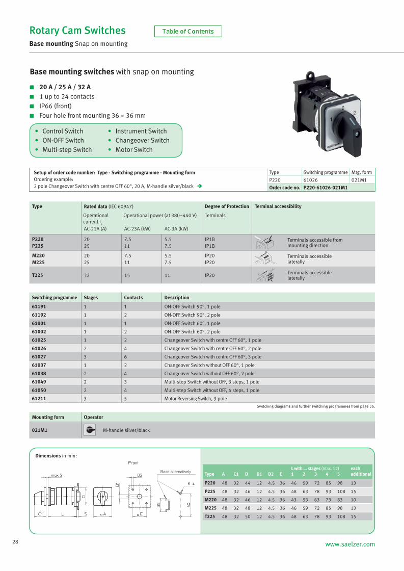
• Control Switch • Instrument Switch• ON-OFF Switch • Changeover Switch• Multi-step Switch • Motor Switch
Rotary Cam SwitchesBase mounting Snap on mounting
Switching diagrams and further switching programmes from page 56.
Switching programme Stages Contacts Description
61191 1 1 ON-OFF Switch 90°, 1 pole
61192 1 2 ON-OFF Switch 90°, 2 pole
61001 1 1 ON-OFF Switch 60°, 1 pole
61002 1 2 ON-OFF Switch 60°, 2 pole
61025 1 2 Changeover Switch with centre OFF 60°, 1 pole
61026 2 4 Changeover Switch with centre OFF 60°, 2 pole
61027 3 6 Changeover Switch with centre OFF 60°, 3 pole
61037 1 2 Changeover Switch without OFF 60°, 1 pole
61038 2 4 Changeover Switch without OFF 60°, 2 pole
61049 2 3 Multi-step Switch without OFF, 3 steps, 1 pole
61050 2 4 Multi-step Switch without OFF, 4 steps, 1 pole
61211 3 5 Motor Reversing Switch, 3 pole
Mounting form Operator
021M1 M-handle silver/black
Dimensions in mm:
Setup of order code number: Type - Switching programme - Mounting formOrdering example:2 pole Changeover Switch with centre OFF 60°, 20 A, M-handle silver/black
Type Switching programme Mtg. form
P220 61026 021M1
Order code no. P220-61026-021M1
Base mounting switches with snap on mounting
20 A / 25 A / 32 A 1 up to 24 contacts IP66 (front) Four hole front mounting 36 × 36 mm
Type Rated data (IEC 60947) Degree of Protection Terminal accessibility
Operational current I
e
Operational power (at 380–440 V) Terminals
AC-21A (A) AC-23A (kW) AC-3A (kW)
P220P225
2025
7.511
5.57.5
IP1BIP1B
Terminals accessible frommounting direction
M220M225
2025
7.511
5.57.5
IP20IP20
Terminals accessiblelaterally
T225 32 15 11 IP20 Terminals accessiblelaterally
L with … stages (max. 12) eachType A C1 D D1 D2 E 1 2 3 4 5 additional
P220 48 32 44 12 4.5 36 46 59 72 85 98 13
P225 48 32 46 12 4.5 36 48 63 78 93 108 15
M220 48 32 46 12 4.5 36 43 53 63 73 83 10
M225 48 32 48 12 4.5 36 46 59 72 85 98 13
T225 48 32 50 12 4.5 36 48 63 78 93 108 15
Base alternatively
NS_engl.indb 28NS_engl.indb 28 14.09.2017 08:57:1214.09.2017 08:57:12

29
• Control Switch • Instrument Switch• ON-OFF Switch • Changeover Switch• Multi-step Switch • Motor Switch
Base mounting switches with snap on mounting for DIN Rail
20 A / 25 A / 32 A 1 up to 24 contacts IP40 (front) Installation mounting for 45 mm aperture in Panel/Distribution boards
Rotary Cam SwitchesBase mounting Snap on mounting for DIN Rail
Mounting form Operator
026N2 N-handle silver/grey
Setup of order code number: Type - Switching programme - Mounting formOrdering example:1 pole Multi-step Switch with OFF, 20 A, N-handle silver/grey
Type Switching programme Mtg. form
P220 61060 026N2
Order code no. P220-61060-026N2
Type Rated data (IEC 60947) Degree of Protection Terminal accessibility
Operational current I
e
Operational power (at 380–440 V) Terminals
AC-21A (A) AC-23A (kW) AC-3A (kW)
P220P225
2025
7.511
5.57.5
IP1BIP1B
Terminals accessible frommounting direction
M220M225
2025
7.511
5.57.5
IP20IP20
Terminals accessiblelaterally
T225 32 15 11 IP20 Terminals accessiblelaterally
Switching diagrams and further switching programmes from page 56.
Switching programme Stages Contacts Description
61191 1 1 ON-OFF Switch 90°, 1 pole
61192 1 2 ON-OFF Switch 90°, 2 pole
61001 1 1 ON-OFF Switch 60°, 1 pole
61002 1 2 ON-OFF Switch 60°, 2 pole
61025 1 2 Changeover Switch with centre OFF 60°, 1 pole
61026 2 4 Changeover Switch with centre OFF 60°, 2 pole
61027 3 6 Changeover Switch with centre OFF 60°, 3 pole
61037 1 2 Changeover Switch without OFF 60°, 1 pole
61060 2 3 Multi-step Switch with OFF, 3 steps, 1 pole
61050 2 4 Multi-step Switch without OFF, 4 steps, 1 pole
61313 3 6 Voltmeter Selector Switch with centre OFF, 3 phase line to line + 3 phase line to N
61325 3 6 Ammeter Selector Switch with centre OFF, 3 transformers, 1 pole
61211 3 5 Motor Reversing Switch, 3 pole
Dimensions in mm:L with … stages (max. 12) each
Type A1 A2 C1 C2 D 1 2 3 4 5 additional
P220 45 52.2 45 24 44 28 41 54 67 80 13
P225 45 52.2 45 24 46 30 45 60 75 90 15
M220 45 52.2 45 24 46 25 35 45 55 65 10
M225 45 52.2 45 24 48 28 41 54 67 80 13
T225 45 52.2 45 24 50 30 45 60 75 90 15
NS_engl.indb 29NS_engl.indb 29 14.09.2017 08:57:1314.09.2017 08:57:13

30 www.saelzer.com
• Control Switch • Instrument Switch• ON-OFF Switch • Changeover Switch• Multi-step Switch • Motor Switch
Base mounting switches with snap on mounting /Door clutch with modular shaft extension
20 A / 25 A / 32 A 1 up to 24 contacts IP66 (front) Four hole front mounting 36 × 36 mm
Rotary Cam SwitchesBase mounting Snap on mounting / Door clutch with modular shaft extension
Mounting form Operator
241M1 M-handle silver/black
Setup of order code number: Type - Switching programme - Mounting formOrdering example:1 pole Multi-step Switch with OFF, 20 A, M-handle silver/black
Type Switching programme Mtg. form
M220 61061 241M1
Order code no. M220-61061-241M1
Type Rated data (IEC 60947) Degree of Protection Terminal accessibility
Operational current I
e
Operational power (at 380–440 V) Terminals
AC-21A (A) AC-23A (kW) AC-3A (kW)
P220P225
2025
7.511
5.57.5
IP1BIP1B
Terminals accessible frommounting direction
M220M225
2025
7.511
5.57.5
IP20IP20
Terminals accessiblelaterally
T225 32 15 11 IP20 Terminals accessiblelaterally
Switching diagrams and further switching programmes from page 56.
Switching programme Stages Contacts Description
61191 1 1 ON-OFF Switch 90°, 1 pole
61192 1 2 ON-OFF Switch 90°, 2 pole
61001 1 1 ON-OFF Switch 60°, 1 pole
61002 1 2 ON-OFF Switch 60°, 2 pole
61025 1 2 Changeover Switch with centre OFF 60°, 1 pole
61026 2 4 Changeover Switch with centre OFF 60°, 2 pole
61027 3 6 Changeover Switch with centre OFF 60°, 3 pole
61037 1 2 Changeover Switch without OFF 60°, 1 pole
61038 2 4 Changeover Switch without OFF 60°, 2 pole
61061 2 4 Multi-step Switch with OFF, 4 steps, 1 pole
61049 2 3 Multi-step Switch without OFF, 3 steps, 1 pole
61050 2 4 Multi-step Switch without OFF, 4 steps, 1 pole
61211 3 5 Motor Reversing Switch, 3 pole
Dimensions in mm:
L with … stages (max. 12) eachType A Cmin Cmax C1 D D1 D2 E 1 2 3 4 additional
P220 48 42 59 32 44 12 4.5 36 40 53 66 79 13
P225 48 42 59 32 46 12 4.5 36 42 57 72 87 15
M220 48 42 59 32 46 12 4.5 36 37 47 57 67 10
M225 48 42 59 32 48 12 4.5 36 40 53 66 79 13
T225 48 42 59 32 50 12 4.5 36 42 57 72 87 15
Modular shaft extensions see page 84.
Base alternativelyDoor
NS_engl.indb 30NS_engl.indb 30 14.09.2017 08:57:1314.09.2017 08:57:13

31
Type Rated data (IEC 60947) Degree of Protection Terminal accessibility
Operational current I
e
Operational power (at 380–440 V) Terminals
AC-21A (A) AC-23A (kW) AC-3A (kW)
P220P225
2025
7.511
5.57.5
IP1BIP1B
Terminals accessible frommounting direction
M220M225
2025
7.511
5.57.5
IP20IP20
Terminals accessiblelaterally
T225 32 15 11 IP20 Terminals accessiblelaterally
Rotary Cam SwitchesBase mounting Snap on mounting / Door clutch with modular shaft extension
Switching diagrams and further switching programmes from page 56.
Setup of order code number: Type - Switching programme - Mounting formOrdering example:4 pole Main/Emergency-Off Switch 90°, 20 A, padlock device with N-handle yellow/red
Type Switching programme Mtg. form
M220 61194 232N4
Order code no. M220-61194-232N4
Switching programme Stages Contacts Description
61191 1 1 ON-OFF Switch 90°, 1 pole
61192 1 2 ON-OFF Switch 90°, 2 pole
61199 2 3 ON-OFF Switch 90°, 3 pole
61194 2 4 ON-OFF Switch 90°, 4 pole, 1 pole early make/late break
61906 3 6 ON-OFF Switch 90°, 6 pole
61919 4 8 ON-OFF Switch 90°, 8 pole, 2 pole early make/late break
Mounting form Operator Main/Emergency-Off Switch Mounting form Operator Main Switch
232N4 padlock device with N-handleyellow/red 232N1
padlock device with N-handleblack
232M4 padlock device with M-handleyellow/red 232M1
padlock device with M-handleblack
232V4 padlockable with V-handleyellow/red 232V1
padlockable with V-handlesilver/black
• Main/Emergency-Off Switch• Main Switch
L with … stages (max. 12) each Type Mounting form A Cmin Cmax C1 D D1 D2 E 1 2 3 4 additional
P220 232N4/232N1 67 42 59 33 44 15 4.5 36 40 53 66 79 13232M4/232M1 67 42 59 38 44 15 4.5 36 40 53 66 79 13232V4/232V1 48 42 59 32 44 12 4.5 36 40 53 66 79 13
P225 232N4/232N1 67 42 59 33 46 15 4.5 36 42 57 72 87 15232M4/232M1 67 42 59 38 46 15 4.5 36 42 57 72 87 15232V4/232V1 48 42 59 32 46 12 4.5 36 42 57 72 87 15
M220 232N4/232N1 67 42 59 33 46 15 4.5 36 37 47 57 67 10232M4/232M1 67 42 59 38 46 15 4.5 36 37 47 57 67 10232V4/232V1 48 42 59 32 46 12 4.5 36 37 47 57 67 10
M225 232N4/232N1 67 42 59 33 48 15 4.5 36 40 53 66 79 13232M4/232M1 67 42 59 38 48 15 4.5 36 40 53 66 79 13232V4/232V1 48 42 59 32 48 12 4.5 36 40 53 66 79 13
T225 232N4/232N1 67 42 59 33 50 15 4.5 36 42 57 72 87 15232M4/232M1 67 42 59 38 50 15 4.5 36 42 57 72 87 15
232V4/232V1 48 42 59 32 50 12 4.5 36 42 57 72 87 15
Dimensions in mm:
Modular shaft extensionssee page 84.
Base mounting switches with snap on mounting /Door clutch with modular shaft extension
20 A / 25 A / 32 A 1 up to 24 contacts IP66 (front) Four hole front mounting 36 × 36 mm
Base alternatively
Door
NS_engl.indb 31NS_engl.indb 31 14.09.2017 08:57:1314.09.2017 08:57:13

32 www.saelzer.com
• Control Switch • Instrument Switch• ON-OFF Switch • Changeover Switch• Multi-step Switch • Motor Switch
Base mounting switches with snap on mounting /Door interlock with modular shaft extension
with N/PE connection link 20 A / 25 A / 32 A 1 up to 24 contacts IP66 (front) Four hole front mounting 36 × 36 mm
Rotary Cam SwitchesBase mounting Snap on mounting / Door interlock with modular shaft extension
Mounting form Operator
242M1 M-handle silver/black
Setup of order code number: Type - Switching programme - Mounting formOrdering example:3 pole ON-OFF Switch 90°, 20 A, M-handle silver/black
Type Switching programme Mtg. form
M220 61199 242M1
Order code no. M220-61199-242M1
Type Rated data (IEC 60947) Degree of Protection Terminal accessibility
Operational current I
e
Operational power (at 380–440 V) Terminals
AC-21A (A) AC-23A (kW) AC-3A (kW)
P220P225
2025
7.511
5.57.5
IP1BIP1B
Terminals accessible frommounting direction
M220M225
2025
7.511
5.57.5
IP20IP20
Terminals accessiblelaterally
T225 32 15 11 IP20 Terminals accessiblelaterally
Switching diagrams and further switching programmes from page 56.
Switching programme Stages Contacts Description
61191 1 1 ON-OFF Switch 90°, 1 pole
61192 1 2 ON-OFF Switch 90°, 2 pole
61199 2 3 ON-OFF Switch 90°, 3 pole
61001 1 1 ON-OFF Switch 60°, 1 pole
61002 1 2 ON-OFF Switch 60°, 2 pole
61025 1 2 Changeover Switch with centre OFF 60°, 1 pole
61026 2 4 Changeover Switch with centre OFF 60°, 2 pole
61027 3 6 Changeover Switch with centre OFF 60°, 3 pole
61037 1 2 Changeover Switch without OFF 60°, 1 pole
61038 2 4 Changeover Switch without OFF 60°, 2 pole
61049 2 3 Multi-step Switch without OFF, 3 steps, 1 pole
61050 2 4 Multi-step Switch without OFF, 4 steps, 1 pole
61211 3 5 Motor Reversing Switch, 3 pole
Dimensions in mm:
L with … stages (max. 12) eachType A Cmin Cmax C1 D D1 D2 E 1 2 3 4 additional
P220 48 42 57 32 44 12 4.5 36 40 53 66 79 13
P225 48 42 57 32 46 12 4.5 36 42 57 72 87 15
M220 48 42 57 32 46 12 4.5 36 37 47 57 67 10
M225 48 42 57 32 48 12 4.5 36 40 53 66 79 13
T225 48 42 57 32 50 12 4.5 36 42 57 72 87 15
Modular shaft extensions see page 84.
Base alternativelyDoor
NS_engl.indb 32NS_engl.indb 32 14.09.2017 08:57:1414.09.2017 08:57:14

33
Type Rated data (IEC 60947) Degree of Protection Terminal accessibility
Operational current I
e
Operational power (at 380–440 V) Terminals
AC-21A (A) AC-23A (kW) AC-3A (kW)
P220P225
2025
7.511
5.57.5
IP1BIP1B
Terminals accessible frommounting direction
M220M225
2025
7.511
5.57.5
IP20IP20
Terminals accessiblelaterally
T225 32 15 11 IP20 Terminals accessiblelaterally
Switching diagrams and further switching programmes from page 56.
Setup of order code number: Type - Switching programme - Mounting formOrdering example:4 pole Main Switch 90°, 20 A, padlock device with M-handle black
Type Switching programme Mtg. form
P220 61194 234M1
Order code no. P220-61194-234M1
Switching programme Stages Contacts Description
61191 1 1 ON-OFF Switch 90°, 1 pole
61192 1 2 ON-OFF Switch 90°, 2 pole
61199 2 3 ON-OFF Switch 90°, 3 pole
61194 2 4 ON-OFF Switch 90°, 4 pole, 1 pole early make/late break
61906 3 6 ON-OFF Switch 90°, 6 pole
61919 4 8 ON-OFF Switch 90°, 8 pole, 2 pole early make/late break
Mounting form Operator Main/Emergency-Off Switch Mounting form Operator Main Switch
234N4 padlock device with N-handleyellow/red 234N1
padlock device with N-handleblack
234M4 padlock device with M-handleyellow/red 234M1
padlock device with M-handleblack
234V4 padlockable with V-handleyellow/red 234V1
padlockable with V-handlesilver/black
• Main/Emergency-Off Switch• Main Switch
L with … stages (max. 12) eachType Mounting form A Cmin Cmax C1 D D1 D2 E 1 2 3 4 additional
P220 234N4/234N1 67 42 57 33 44 15 4.5 36 40 53 66 79 13234M4/234M1 67 42 57 38 44 15 4.5 36 40 53 66 79 13234V4/234V1 48 42 57 32 44 12 4.5 36 40 53 66 79 13
P225 234N4/234N1 67 42 57 33 46 15 4.5 36 42 57 72 87 15234M4/234M1 67 42 57 38 46 15 4.5 36 42 57 72 87 15234V4/234V1 48 42 57 32 46 12 4.5 36 42 57 72 87 15
M220 234N4/234N1 67 42 57 33 46 15 4.5 36 37 47 57 67 10234M4/234M1 67 42 57 38 46 15 4.5 36 37 47 57 67 10234V4/234V1 48 42 57 32 46 12 4.5 36 37 47 57 67 10
M225 234N4/234N1 67 42 57 33 48 15 4.5 36 40 53 66 79 13234M4/234M1 67 42 57 38 48 15 4.5 36 40 53 66 79 13234V4/234V1 48 42 57 32 48 12 4.5 36 40 53 66 79 13
T225 234N4/234N1 67 42 57 33 50 15 4.5 36 42 57 72 87 15234M4/234M1 67 42 57 38 50 15 4.5 36 42 57 72 87 15
234V4/234V1 48 42 57 32 50 12 4.5 36 42 57 72 87 15
Dimensions in mm:
Modular shaft extensionssee page 84.
Base mounting switches with snap on mounting /Door interlock with modular shaft extension
with N/PE connection link 20 A / 25 A / 32 A 1 up to 24 contacts IP66 (front) Four hole front mounting 36 × 36 mm
Rotary Cam SwitchesBase mounting Snap on mounting / Door interlock with modular shaft extension
Base alternativelyDoor
NS_engl.indb 33NS_engl.indb 33 14.09.2017 08:57:1414.09.2017 08:57:14

34 www.saelzer.com
• ON-OFF Switch • Changeover Switch• Multi-step Switch • Motor Switch
Base mounting switches with four hole mounting 68 × 68 mm
50 A / 63 A 1 up to 24 contacts IP55 (front) Four hole front mounting 48 × 48 mm
Type Rated data (IEC 60947) Terminal accessibility
Operational current I
e
Operational power (at 380–440 V)
AC-21A (A) AC-23A (kW) AC-3A (kW)
S432S440
5063
2230
2230
Terminals accessiblelaterally
Rotary Cam SwitchesBase mounting Four hole mounting 68 × 68 mm
Switching diagrams and further switching programmes from page 56.
Mounting form Operator
002M1 M-handle silver/black
Dimensions in mm:
L with … stages (max. 12) eachType A C1 D D1 D2 E1 E2 1 2 3 4 5 6 additional
S432 64 39 65 12 5 48 68 56 74 92 110 128 146 18
S440 64 39 70 12 5 48 68 61 82 103 124 145 166 21
Setup of order code number: Type - Switching programme - Mounting formOrdering example:3 pole Changeover Switch with centre OFF 60°, 50 A, M-handle silver/black
Type Switching programme Mtg. form
S432 61027 002M1
Order code no. S432-61027-002M1
Switching programme Stages Contacts Description
61191 1 1 ON-OFF Switch 90°, 1 pole
61192 1 2 ON-OFF Switch 90°, 2 pole
61001 1 1 ON-OFF Switch 60°, 1 pole
61002 1 2 ON-OFF Switch 60°, 2 pole
61003 2 3 ON-OFF Switch 60°, 3 pole
61025 1 2 Changeover Switch with centre OFF 60°, 1 pole
61026 2 4 Changeover Switch with centre OFF 60°, 2 pole
61027 3 6 Changeover Switch with centre OFF 60°, 3 pole
61037 1 2 Changeover Switch without OFF 60°, 1 pole
61038 2 4 Changeover Switch without OFF 60°, 2 pole
61050 2 4 Multi-step Switch without OFF, 4 steps, 1 pole
61211 3 5 Motor Reversing Switch, 3 pole
Base
Front
NS_engl.indb 34NS_engl.indb 34 14.09.2017 08:57:1514.09.2017 08:57:15

35
Dimensions in mm:
Type Rated data (IEC 60947) Terminal accessibility
Operational current I
e
Operational power (at 380–440 V)
AC-21A (A) AC-23A (kW) AC-3A (kW)
S606S608S612
80100160
455575
303745
Terminals accessiblelaterally
Switching diagrams and further switching programmes from page 56.
Setup of order code number: Type - Switching programme - Mounting formOrdering example:3 pole Changeover Switch with centre OFF 60°, 80 A, M-handle silver/black
Type Switching programme Mtg. form
S606 61027 002M1
Order code no. S606-61027-002M1
L with … stages (max. 12) eachType Mtg. form A C1 D D1 D2 E1 E2 1 2 3 4 additional
S606 002M1 88 52 84 15 5.5 68 68 64 86 108 130 22
002G1 88 66 84 15 5.5 68 68 64 86 108 130 22
S608 002M1 88 52 88 15 5.5 68 68 71 97 123 149 26
002G1 88 66 88 15 5.5 68 68 71 97 123 149 26
S612 002M1 88 52 88 15 5.5 68 68 77 109 141 173 32
002G1 88 66 88 15 5.5 68 68 77 109 141 173 32
Mounting form Operator Mounting form Operator
002M1 M-handle silver/black 002G1 G-handle silver/black
• ON-OFF Switch • Changeover Switch• Multi-step Switch • Motor Switch
Base mounting switches with four hole mounting 68 × 68 mm
80 A / 100 A / 160 A 1 up to 24 contacts IP55 (front) Four hole front mounting 68 × 68 mm
Rotary Cam SwitchesBase mounting Four hole mounting 68 × 68 mm
Switching programme Stages Contacts Description
61191 1 1 ON-OFF Switch 90°, 1 pole
61192 1 2 ON-OFF Switch 90°, 2 pole
61001 1 1 ON-OFF Switch 60°, 1 pole
61002 1 2 ON-OFF Switch 60°, 2 pole
61003 2 3 ON-OFF Switch 60°, 3 pole
61025 1 2 Changeover Switch with centre OFF 60°, 1 pole
61026 2 4 Changeover Switch with centre OFF 60°, 2 pole
61027 3 6 Changeover Switch with centre OFF 60°, 3 pole
61037 1 2 Changeover Switch without OFF 60°, 1 pole
61038 2 4 Changeover Switch without OFF 60°, 2 pole
61050 2 4 Multi-step Switch without OFF, 4 steps, 1 pole
61211 3 5 Motor Reversing Switch, 3 pole
Base
Front
NS_engl.indb 35NS_engl.indb 35 14.09.2017 08:57:1514.09.2017 08:57:15

36 www.saelzer.com
• ON-OFF Switch • Changeover Switch• Multi-step Switch • Motor Switch
Base mounting switches with four hole mounting 68 × 68 mm /Door clutch
50 A / 63 A 1 up to 24 contacts IP55 (front) Four hole front mounting 48 × 48 mm
Type Rated data (IEC 60947) Terminal accessibility
Operational current I
e
Operational power (at 380–440 V)
AC-21A (A) AC-23A (kW) AC-3A (kW)
S432S440
5063
2230
2230
Terminals accessiblelaterally
Rotary Cam SwitchesBase mounting Four hole mounting 68 × 68 mm / Door clutch
Switching diagrams and further switching programmes from page 56.
Mounting form Operator
041M1 M-handle silver/black
Dimensions in mm:
L with … stages (max. 12) eachType A Cmin Cmax C1 D D1 D2 E1 E2 1 2 3 4 additional
S432 64 42 56 39 65 12 5 48 68 51 69 87 105 18
S440 64 42 56 39 70 12 5 48 68 56 77 98 119 21
Setup of order code number: Type - Switching programme - Mounting formOrdering example:3 pole ON-OFF Switch 60°, 50 A, M-handle silver/black
Type Switching programme Mtg. form
S432 61006 041M1
Order code no. S432-61006-041M1
Switching programme Stages Contacts Description
61191 1 1 ON-OFF Switch 90°, 1 pole
61192 1 2 ON-OFF Switch 90°, 2 pole
61001 1 1 ON-OFF Switch 60°, 1 pole
61002 1 2 ON-OFF Switch 60°, 2 pole
61003 2 3 ON-OFF Switch 60°, 3 pole
61006 3 6 ON-OFF Switch 60°, 6 pole
61025 1 2 Changeover Switch with centre OFF 60°, 1 pole
61026 2 4 Changeover Switch with centre OFF 60°, 2 pole
61027 3 6 Changeover Switch with centre OFF 60°, 3 pole
61037 1 2 Changeover Switch without OFF 60°, 1 pole
61038 2 4 Changeover Switch without OFF 60°, 2 pole
61050 2 4 Multi-step Switch without OFF, 4 steps, 1 pole
61211 3 5 Motor Reversing Switch, 3 pole
NS_engl.indb 36NS_engl.indb 36 14.09.2017 08:57:1514.09.2017 08:57:15

37
Dimensions in mm:
Type Rated data (IEC 60947) Terminal accessibility
Operational current I
e
Operational power (at 380–440 V)
AC-21A (A) AC-23A (kW) AC-3A (kW)
S606S608S612
80100160
455575
303745
Terminals accessiblelaterally
Switching diagrams and further switching programmes from page 56.
Setup of order code number: Type - Switching programme - Mounting formOrdering example:3 pole ON-OFF Switch 90°, 80 A, M-handle silver/black
Type Switching programme Mtg. form
S606 61199 041M1
Order code no. S606-61199-041M1
L with … stages (max. 12) eachType Mtg. form A Cmin Cmax C1 D D1 D2 E1 E2 1 2 3 4 additional
S606 041M1 88 48 60 52 84 18 5.5 68 68 58 80 107 129 22
041G1 88 48 60 66 84 18 5.5 68 68 58 80 107 129 22
S608 041M1 88 48 60 52 88 18 5.5 68 68 65 91 117 143 26
041G1 88 48 60 66 88 18 5.5 68 68 65 91 117 143 26
S612 041M1 88 48 60 52 88 18 5.5 68 68 71 103 135 167 32
041G1 88 48 60 66 88 18 5.5 68 68 71 103 135 167 32
Mounting form Operator Mounting form Operator
041M1 M-handle silver/black 041G1 G-handle silver/black
• ON-OFF Switch • Changeover Switch• Multi-step Switch • Motor Switch
Base mounting switches with four hole mounting 68 × 68 mm /Door clutch
80 A / 100 A / 160 A 1 up to 24 contacts IP55 (front) Four hole front mounting 68 × 68 mm
Rotary Cam SwitchesBase mounting Four hole mounting 68 × 68 mm / Door clutch
Switching programme Stages Contacts Description
61192 1 2 ON-OFF Switch 90°, 2 pole
61199 2 3 ON-OFF Switch 90°, 3 pole
61001 1 1 ON-OFF Switch 60°, 1 pole
61002 1 2 ON-OFF Switch 60°, 2 pole
61003 2 3 ON-OFF Switch 60°, 3 pole
61025 1 2 Changeover Switch with centre OFF 60°, 1 pole
61026 2 4 Changeover Switch with centre OFF 60°, 2 pole
61027 3 6 Changeover Switch with centre OFF 60°, 3 pole
61037 1 2 Changeover Switch without OFF 60°, 1 pole
61038 2 4 Changeover Switch without OFF 60°, 2 pole
61050 2 4 Multi-step Switch without OFF, 4 steps, 1 pole
61211 3 5 Motor Reversing Switch, 3 pole
NS_engl.indb 37NS_engl.indb 37 14.09.2017 08:57:1614.09.2017 08:57:16

38 www.saelzer.com
• ON-OFF Switch • Changeover Switch• Multi-step Switch • Motor Switch
Base mounting switches with four hole mounting 68 × 68 mm /Door interlock
50 A / 63 A 1 up to 24 contacts IP55 (front) Four hole front mounting 48 × 48 mm
Type Rated data (IEC 60947) Terminal accessibility
Operational current I
e
Operational power (at 380–440 V)
AC-21A (A) AC-23A (kW) AC-3A (kW)
S432S440
5063
2230
2230
Terminals accessiblelaterally
Rotary Cam SwitchesBase mounting Four hole mounting 68 × 68 mm / Door interlock
Switching diagrams and further switching programmes from page 56.
Mounting form Operator
042M1 M-handle silver/black
Dimensions in mm:
L with … stages (max. 12) eachType A Cmin Cmax C1 D D1 D2 E1 E2 1 2 3 4 additional
S432 64 42 56 39 65 15 5 48 68 51 69 87 105 18
S440 64 42 56 39 70 15 5 48 68 56 77 98 119 21
Setup of order code number: Type - Switching programme - Mounting formOrdering example:3 pole ON-OFF Switch 90°, 50 A, M-handle silver/black
Type Switching programme Mtg. form
S432 61199 042M1
Order code no. S432-61199-042M1
Switching programme Stages Contacts Description
61191 1 1 ON-OFF Switch 90°, 1 pole
61192 1 2 ON-OFF Switch 90°, 2 pole
61199 2 3 ON-OFF Switch 90°, 3 pole
61001 1 1 ON-OFF Switch 60°, 1 pole
61002 1 2 ON-OFF Switch 60°, 2 pole
61003 2 3 ON-OFF Switch 60°, 3 pole
61025 1 2 Changeover Switch with centre OFF 60°, 1 pole
61026 2 4 Changeover Switch with centre OFF 60°, 2 pole
61027 3 6 Changeover Switch with centre OFF 60°, 3 pole
61037 1 2 Changeover Switch without OFF 60°, 1 pole
61038 2 4 Changeover Switch without OFF 60°, 2 pole
61050 2 4 Multi-step Switch without OFF, 4 steps, 1 pole
61211 3 5 Motor Reversing Switch, 3 pole
NS_engl.indb 38NS_engl.indb 38 14.09.2017 08:57:1614.09.2017 08:57:16

39
Dimensions in mm:
Type Rated data (IEC 60947) Terminal accessibility
Operational current I
e
Operational power (at 380–440 V)
AC-21A (A) AC-23A (kW) AC-3A (kW)
S606S608S612
80100160
455575
303745
Terminals accessiblelaterally
Switching diagrams and further switching programmes from page 56.
Setup of order code number: Type - Switching programme - Mounting formOrdering example:3 pole ON-OFF Switch 90°, 80 A, M-handle silver/black
Type Switching programme Mtg. form
S606 61199 042M1
Order code no. S606-61199-042M1
L with … stages (max. 12) eachType Mtg. form A Cmin Cmax C1 D D1 D2 E1 E2 1 2 3 4 additional
S606 042M1 88 48 60 52 84 18 5.5 68 68 58 80 107 129 22
042G1 88 48 60 66 84 18 5.5 68 68 58 80 107 129 22
S608 042M1 88 48 60 52 88 18 5.5 68 68 65 91 117 143 26
042G1 88 48 60 66 88 18 5.5 68 68 65 91 117 143 26
S612 042M1 88 48 60 52 88 18 5.5 68 68 71 103 135 167 32
042G1 88 48 60 66 88 18 5.5 68 68 71 103 135 167 32
Mounting form Operator Mounting form Operator
042M1 M-handle silver/black 042G1 G-handle silver/black
• ON-OFF Switch • Changeover Switch• Multi-step Switch • Motor Switch
Base mounting switches with four hole mounting 68 × 68 mm /Door interlock
80 A / 100 A / 160 A 1 up to 24 contacts IP55 (front) Four hole front mounting 68 × 68 mm
Rotary Cam SwitchesBase mounting Four hole mounting 68 × 68 mm / Door interlock
Switching programme Stages Contacts Description
61192 1 2 ON-OFF Switch 90°, 2 pole
61199 2 3 ON-OFF Switch 90°, 3 pole
61001 1 1 ON-OFF Switch 60°, 1 pole
61002 1 2 ON-OFF Switch 60°, 2 pole
61003 2 3 ON-OFF Switch 60°, 3 pole
61025 1 2 Changeover Switch with centre OFF 60°, 1 pole
61026 2 4 Changeover Switch with centre OFF 60°, 2 pole
61027 3 6 Changeover Switch with centre OFF 60°, 3 pole
61037 1 2 Changeover Switch without OFF 60°, 1 pole
61038 2 4 Changeover Switch without OFF 60°, 2 pole
61050 2 4 Multi-step Switch without OFF, 4 steps, 1 pole
61211 3 5 Motor Reversing Switch, 3 pole
NS_engl.indb 39NS_engl.indb 39 14.09.2017 08:57:1614.09.2017 08:57:16

40 www.saelzer.com
• ON-OFF Switch • Changeover Switch• Multi-step Switch • Motor Switch
Base mounting switches with four hole mounting 104 × 104 mm
315 A 1 up to 24 contacts IP55 (front) Four hole front mounting 104 × 104 mm
Type Rated data (IEC 60947) Terminal accessibility
Operational current I
e
Operational power (at 380–440 V)
AC-21A (A) AC-23A (kW) AC-3A (kW)
S825 315 132 55 Terminals accessiblelaterally
Rotary Cam SwitchesBase mounting Four hole mounting 104 × 104 mm
Switching diagrams and further switching programmes from page 56.
Setup of order code number: Type - Switching programme - Mounting formOrdering example:2 pole Changeover Switch with centre OFF 60°, 315 A, G-handle silver/black
Type Switching programme Mtg. form
S825 61026 002G1
Order code no. S825-61026-002G1
Mounting form Operator
002G1 G-handle silver/black
Dimensions in mm:
L with … stages (max. 12) eachType A C1 D DAW D1 D2 E1 E2 1 2 3 4 5 6 additional
S825 130 74 120 210 20 5.5 104 104 96 132 168 204 240 276 36
Switching programme Stages Contacts Description
61191 1 1 ON-OFF Switch 90°, 1 pole
61192 1 2 ON-OFF Switch 90°, 2 pole
61001 1 1 ON-OFF Switch 60°, 1 pole
61002 1 2 ON-OFF Switch 60°, 2 pole
61003 2 3 ON-OFF Switch 60°, 3 pole
61025 1 2 Changeover Switch with centre OFF 60°, 1 pole
61026 2 4 Changeover Switch with centre OFF 60°, 2 pole
61027 3 6 Changeover Switch with centre OFF 60°, 3 pole
61037 1 2 Changeover Switch without OFF 60°, 1 pole
61038 2 4 Changeover Switch without OFF 60°, 2 pole
61050 2 4 Multi-step Switch without OFF, 4 steps, 1 pole
NS_engl.indb 40NS_engl.indb 40 14.09.2017 08:57:1714.09.2017 08:57:17

41
• ON-OFF Switch • Changeover Switch• Multi-step Switch • Motor Switch
Base mounting switches with four hole mounting 104 × 104 mm /Door clutch
315 A 1 up to 24 contacts IP55 (front) Four hole front mounting 104 × 104 mm
Type Rated data (IEC 60947) Terminal accessibility
Operational current I
e
Operational power (at 380–440 V)
AC-21A (A) AC-23A (kW) AC-3A (kW)
S825 315 132 55 Terminals accessiblelaterally
Rotary Cam SwitchesBase mounting Four hole mounting 104 × 104 mm / Door clutch
Switching diagrams and further switching programmes from page 56.
Setup of order code number: Type - Switching programme - Mounting formOrdering example:3 pole Changeover Switch with centre OFF 60°, 315 A, G-handle silver/black
Type Switching programme Mtg. form
S825 61027 041G1
Order code no. S825-61027-041G1
Mounting form Operator
041G1 G-handle silver/black
Dimensions in mm:
L with … stages (max. 12) eachType A Cmin
Cmax C1 D DAW D1 D2 E1 E2 1 2 3 4 additional
S825 130 75 102 74 120 210 20 5.5 104 104 90 126 162 198 36
Switching programme Stages Contacts Description
61191 1 1 ON-OFF Switch 90°, 1 pole
61192 1 2 ON-OFF Switch 90°, 2 pole
61001 1 1 ON-OFF Switch 60°, 1 pole
61002 1 2 ON-OFF Switch 60°, 2 pole
61003 2 3 ON-OFF Switch 60°, 3 pole
61025 1 2 Changeover Switch with centre OFF 60°, 1 pole
61026 2 4 Changeover Switch with centre OFF 60°, 2 pole
61027 3 6 Changeover Switch with centre OFF 60°, 3 pole
61037 1 2 Changeover Switch without OFF 60°, 1 pole
61038 2 4 Changeover Switch without OFF 60°, 2 pole
61050 2 4 Multi-step Switch without OFF, 4 steps, 1 pole
NS_engl.indb 41NS_engl.indb 41 14.09.2017 08:57:1814.09.2017 08:57:18

42 www.saelzer.com
• ON-OFF Switch • Changeover Switch• Multi-step Switch • Motor Switch
Base mounting switches with four hole mounting 104 × 104 mm /Door interlock
315 A 1 up to 24 contacts IP55 (front) Four hole front mounting 104 × 104 mm
Type Rated data (IEC 60947) Terminal accessibility
Operational current I
e
Operational power (at 380–440 V)
AC-21A (A) AC-23A (kW) AC-3A (kW)
S825 315 132 55 Terminals accessiblelaterally
Rotary Cam SwitchesBase mounting Four hole mounting 104 × 104 mm / Door interlock
Switching diagrams and further switching programmes from page 56.
Setup of order code number: Type - Switching programme - Mounting formOrdering example:3 pole ON-OFF Switch 90°, 315 A, G-handle silver/black
Type Switching programme Mtg. form
S825 61199 042G1
Order code no. S825-61199-042G1
Mounting form Operator
042G1 G-handle silver/black
Dimensions in mm:
L with … stages (max. 12) eachType A Cmin
Cmax C1 D DAW D1 D2 E1 E2 1 2 3 4 additional
S825 130 75 102 74 120 210 20 5.5 104 104 90 126 162 198 36
Switching programme Stages Contacts Description
61191 1 1 ON-OFF Switch 90°, 1 pole
61192 1 2 ON-OFF Switch 90°, 2 pole
61199 2 3 ON-OFF Switch 90°, 3 pole
61001 1 1 ON-OFF Switch 60°, 1 pole
61002 1 2 ON-OFF Switch 60°, 2 pole
61003 2 3 ON-OFF Switch 60°, 3 pole
61025 1 2 Changeover Switch with centre OFF 60°, 1 pole
61026 2 4 Changeover Switch with centre OFF 60°, 2 pole
61027 3 6 Changeover Switch with centre OFF 60°, 3 pole
61037 1 2 Changeover Switch without OFF 60°, 1 pole
61038 2 4 Changeover Switch without OFF 60°, 2 pole
61050 2 4 Multi-step Switch without OFF, 4 steps, 1 pole
NS_engl.indb 42NS_engl.indb 42 14.09.2017 08:57:1814.09.2017 08:57:18

43
• Control Switch • Instrument Switch• ON-OFF Switch • Changeover Switch• Multi-step Switch • Motor Switch
Enclosed Switches with insulated enclosure 68 × 68 × 53 mm
20 A 1 up to 4 contacts IP65 Insulated polycarbonate enclosure
Rotary Cam SwitchesEnclosed Switches with insulated enclosure 68 × 68 × 53 mm
Setup of order code number: Type - Switching programme - Mounting formOrdering example:1 pole Multi-step Switch without OFF, 20 A, N-handle silver/black
Type Switching programme Mtg. form
M220 61049 107M1
Order code no. M220-61049-107M1
Type Rated data (IEC 60947) Terminal accessibility
Operational current I
e
Operational power (at 380–440 V)
AC-21A (A) AC-23A (kW) AC-3A (kW)
M220 20 7.5 5.5 Terminals accessiblelaterally
Switching diagrams and further switching programmes from page 56.
Switching programme Stages Contacts Description
61191 1 1 ON-OFF Switch 90°, 1 pole
61192 1 2 ON-OFF Switch 90°, 2 pole
61199 2 3 ON-OFF Switch 90°, 3 pole
61194 2 4 ON-OFF Switch 90°, 4 pole, 1 pole early make/late break
61001 1 1 ON-OFF Switch 60°, 1 pole
61002 1 2 ON-OFF Switch 60°, 2 pole
61003 2 3 ON-OFF Switch 60°, 3 pole
61025 1 2 Changeover Switch with centre OFF 60°, 1 pole
61026 2 4 Changeover Switch with centre OFF 60°, 2 pole
61037 1 2 Changeover Switch without OFF 60°, 1 pole
61049 2 3 Multi-step Switch without OFF, 3 steps, 1 pole
61050 2 4 Multi-step Switch without OFF, 4 steps, 1 pole
61210 2 4 Motor Reversing Switch, 2 pole
Mounting form Operator
107M1 M-handle silver/black
Dimensions in mm:
Type H1 B1 T1 T2 2 × M H2 B2
M220 68 68 53 25 16 36 50
NS_engl.indb 43NS_engl.indb 43 14.09.2017 08:57:1814.09.2017 08:57:18

44 www.saelzer.com
Enclosed Switches with insulated enclosure 68 × 68 × 53 mm
20 A 1 up to 4 contacts IP65 Insulated polycarbonate enclosure
Rotary Cam SwitchesEnclosed Switches with insulated enclosure 68 × 68 × 53 mm
Setup of order code number: Type - Switching programme - Mounting formOrdering example:2 pole Main/Emergency-Off Switch 90°, 20 A, padlock device with M-handle yellow/red
Type Switching programme Mtg. form
M220 61192 117M4
Order code no. M220-61192-117M4
Type Rated data (IEC 60947) Terminal accessibility
Operational current I
e
Operational power (at 380–440 V)
AC-21A (A) AC-23A (kW) AC-3A (kW)
M220 20 7.5 5.5 Terminals accessiblelaterally
Switching diagrams and further switching programmes from page 56.
Switching programme Stages Contacts Description
61191 1 1 ON-OFF Switch 90°, 1 pole
61192 1 2 ON-OFF Switch 90°, 2 pole
61199 2 3 ON-OFF Switch 90°, 3 pole
61194 2 4 ON-OFF Switch 90°, 4 pole, 1 pole early make/late break
Dimensions in mm:
Type H1 B1 T1 T2 2 × M H2 B2
M220 68 68 53 31 16 36 50
• Main/Emergency-Off Switch• Main Switch
Mounting form Operator Main/Emergency-Off Switch Mounting form Operator Main Switch
117M4 padlock device with M-handleyellow/red 117M1
padlock device with M-handleblack
NS_engl.indb 44NS_engl.indb 44 14.09.2017 08:57:1814.09.2017 08:57:18

45
Switching diagrams and further switching programmes from page 56.
Switching programme Stages Contacts Description
61191 for type P220 1 1 ON-OFF Switch 90°, 1 pole
61192 for type P220 1 2 ON-OFF Switch 90°, 2 pole
61001 for type P220 1 1 ON-OFF Switch 60°, 1 pole
61002 for type P220 1 2 ON-OFF Switch 60°, 2 pole
61025 for type P220 1 2 Changeover Switch with centre OFF 60°, 1 pole
61037 for type P220 1 2 Changeover Switch without OFF 60°, 1 pole
61003 for type M220 2 3 ON-OFF Switch 60°, 3 pole
61026 for type M220 2 4 Changeover Switch with centre OFF 60°, 2 pole
61038 for type M220 2 4 Changeover Switch without OFF 60°, 2 pole
61049 for type M220 2 3 Multi-step Switch without OFF, 3 steps, 1 pole
61050 for type M220 2 4 Multi-step Switch without OFF, 4 steps, 1 pole
61210 for type M220 2 4 Motor Reversing Switch, 2 pole
Mounting form Operator
076M1 M-handle silver/black
Dimensions in mm:
Setup of order code number: Type - Switching programme - Mounting formOrdering example:2 pole Changeover Switch without OFF 60°, 20 A, M-handle silver/black
Type Switching programme Mtg. form
M220 61038 076M1
Order code no. M220-61038-076M1
Type Contacts Rated data (IEC 60947) Terminal accessibility
Operational current I
e
Operational power (at 380–440 V)
AC-21A (A) AC-23A (kW) AC-3A (kW)
P220 1 to 2 20 7.5 5.5 Terminals accessible frommounting direction
M220 1 to 4 20 7.5 5.5 Terminals accessiblelaterally
• Control Switch • Instrument Switch• ON-OFF Switch • Changeover Switch• Multi-step Switch • Motor Switch
Enclosed Switches with insulated enclosure 100 × 80 × 65 mm
20 A 1 up to max. 4 contacts IP66 Insulated polycarbonate enclosure
Rotary Cam SwitchesEnclosed Switches with insulated enclosure 100 × 80 × 65 mm
Type H1 B1 T1 T2 2 × M H2
P220 100 80 65 32 20 90
M220 100 80 65 32 20 90
NS_engl.indb 45NS_engl.indb 45 14.09.2017 08:57:1814.09.2017 08:57:18

46 www.saelzer.com
Switching diagrams and further switching programmes from page 56.
Switching programme Stages Contacts Description
61001 for type P220 1 1 ON-OFF Switch 60°, 1 pole
61002 for type P220 1 2 ON-OFF Switch 60°, 2 pole
61025 for type P220 1 2 Changeover Switch with centre OFF 60°, 1 pole
61151 for type P220 1 2 Changeover Switch with centre OFF 90°, 1 pole
61003 for type M220 2 3 ON-OFF Switch 60°, 3 pole
61026 for type M220 2 4 Changeover Switch with centre OFF 60°, 2 pole
61151 for type M220 1 2 Changeover Switch with centre OFF 90°, 1 pole
61152 for type M220 2 4 Changeover Switch with centre OFF 90°, 2 pole
61210 for type M220 2 4 Motor Reversing Switch, 2 pole
Mounting form Operator Padlockable options
076V1 padlockable with V-handle silver/black padlockable 12h
078V1 padlockable with V-handle silver/black 3 positions padlockable (9h/12h/03h)(only for Changeover Switches with 90° switching angle)
Dimensions in mm:
Setup of order code number: Type - Switching programme - Mounting formOrdering example:2 pole Changeover Switch 90°, 20 A, padlockable with V-handle silver/black
Type Switching programme Mtg. form
M220 61152 076V1
Order code no. M220-61152-076V1
Type Contacts Rated data (IEC 60947) Terminal accessibility
Operational current I
e
Operational power (at 380–440 V)
AC-21A (A) AC-23A (kW) AC-3A (kW)
P220 1 to 2 20 7.5 5.5 Terminals accessible frommounting direction
M220 1 to 4 20 7.5 5.5 Terminals accessiblelaterally
• Control Switch • Instrument Switch• ON-OFF Switch • Changeover Switch• Multi-step Switch • Motor Switch
Enclosed Switches with insulated enclosure 100 × 80 × 65 mm
20 A 1 up to max. 4 contacts IP66 Insulated polycarbonate enclosure
Rotary Cam SwitchesEnclosed Switches with insulated enclosure 100 × 80 × 65 mm
Type H1 B1 T1 T2 2 × M H2
P220 100 80 65 32 20 90
M220 100 80 65 32 20 90
NS_engl.indb 46NS_engl.indb 46 14.09.2017 08:57:1914.09.2017 08:57:19

47
Switching diagrams and further switching programmes from page 56.
Switching programme Stages Contacts Description
61191 for type P220 1 1 ON-OFF Switch 90°, 1 pole
61192 for type P220 1 2 ON-OFF Switch 90°, 2 pole
61191 for type M220 1 1 ON-OFF Switch 90°, 1 pole
61192 for type M220 1 2 ON-OFF Switch 90°, 2 pole
61199 for type M220 2 3 ON-OFF Switch 90°, 3 pole
61194 for type M220 2 4 ON-OFF Switch 90°, 4 pole, 1 pole early make/late break
Dimensions in mm:
Setup of order code number: Type - Switching programme - Mounting formOrdering example:2 pole Main Switch 90°, 20 A, padlock device with N-handle yellow/red
Type Switching programme Mtg. form
P220 61192 077N4
Order code no. P220-61192-077N4
Type Contacts Rated data (IEC 60947) Terminal accessibility
Operational current I
e
Operational power (at 380–440 V)
AC-21A (A) AC-23A (kW) AC-3A (kW)
P220 1 to 2 20 7.5 5.5 Terminals accessible frommounting direction
M220 1 to 4 20 7.5 5.5 Terminals accessiblelaterally
Enclosed Switches with insulated enclosure 100 × 80 × 65 mm
20 A 1 up to max. 4 contacts IP66 Insulated polycarbonate enclosure
Rotary Cam SwitchesEnclosed Switches with insulated enclosure 100 × 80 × 65 mm
Mounting form H1 B1 T1 T2 2 × M H2
077N4/077N1 100 80 65 33 20 90
077M4/077M1 100 80 65 38 20 90
077V4/077V1 100 80 65 32 20 90
• Main/Emergency-Off Switch• Main Switch
Mounting form Operator Main/Emergency-Off Switch Mounting form Operator Main Switch
077N4 padlock device with N-handleyellow/red 077N1
padlock device with N-handleblack
077M4 padlock device with M-handleyellow/red 077M1
padlock device with M-handleblack
077V4 padlockable with V-handleyellow/red 077V1
padlockable with V-handlesilver/black
NS_engl.indb 47NS_engl.indb 47 14.09.2017 08:57:1914.09.2017 08:57:19

48 www.saelzer.com
Switching diagrams and further switching programmes from page 56.
Switching programme Stages Contacts Description
61199 for type P220 2 3 ON-OFF Switch 90°, 3 pole
61194 for type P220 2 4 ON-OFF Switch 90°, 4 pole, 1 pole early make/late break
61026 for type P220 2 4 Changeover Switch with centre OFF 60°, 2 pole
61038 for type P220 2 4 Changeover Switch without OFF 60°, 2 pole
61049 for type P220 2 3 Multi-step Switch without OFF, 3 steps, 1 pole
61211 for type P220 3 5 Motor Reversing Switch, 3 pole
61906 for type M220 3 6 ON-OFF Switch 90°, 6 pole
61919 for type M220 4 8 ON-OFF Switch 90°, 8 pole, 2 pole early make/late break
61028 for type M220 4 8 Changeover Switch with centre OFF 60°, 4 pole
61039 for type M220 3 6 Changeover Switch without OFF 60°, 3 pole
61040 for type M220 4 8 Changeover Switch without OFF 60°, 4 pole
61211 for type M220 3 5 Motor Reversing Switch, 3 pole
Mounting form Operator
176M1 M-handle silver/black
Dimensions in mm:
Setup of order code number: Type - Switching programme - Mounting formOrdering example:4 pole Changeover Switch without OFF 60°, 20 A, M-handle silver/black
Type Switching programme Mtg. form
M220 61040 176M1
Order code no. M220-61040-176M1
Type Contacts Rated data (IEC 60947) Terminal accessibility
Operational current I
e
Operational power (at 380–440 V)
AC-21A (A) AC-23A (kW) AC-3A (kW)
P220 3 to 6 20 7.5 5.5 Terminals accessible frommounting direction
M220 5 to 8 20 7.5 5.5 Terminals accessiblelaterally
• Control Switch • Instrument Switch• ON-OFF Switch • Changeover Switch• Multi-step Switch • Motor Switch
Enclosed Switches with insulated enclosure 100 × 80 × 85 mm
20 A 3 up to max. 8 contacts IP66 Insulated polycarbonate enclosure
Rotary Cam SwitchesEnclosed Switches with insulated enclosure 100 × 80 × 85 mm
Type H1 B1 T1 T2 2 × M H2
P220 100 80 85 32 20 90
M220 100 80 85 32 20 90
NS_engl.indb 48NS_engl.indb 48 14.09.2017 08:57:1914.09.2017 08:57:19

49
Switching diagrams and further switching programmes from page 56.
Switching programme Stages Contacts Description
61003 for type P220 2 3 ON-OFF Switch 60°, 3 pole
61027 for type P220 3 6 Changeover Switch with centre OFF 60°, 3 pole
61152 for type P220 2 4 Changeover Switch with centre OFF 90°, 2 pole
61153 for type P220 3 6 Changeover Switch with centre OFF 90°, 3 pole
61211 for type P220 3 5 Motor Reversing Switch, 3 pole
61027 for type M220 3 6 Changeover Switch with centre OFF 60°, 3 pole
61028 for type M220 4 8 Changeover Switch with centre OFF 60°, 4 pole
61153 for type M220 3 6 Changeover Switch with centre OFF 90°, 3 pole
61211 for type M220 3 5 Motor Reversing Switch, 3 pole
Dimensions in mm:
Setup of order code number: Type - Switching programme - Mounting formOrdering example:2 pole Changeover Switch 90°, 20 A, padlockable with V-handle silver/black
Type Switching programme Mtg. form
P220 61152 178V1
Order code no. P220-61152-178V1
Type Contacts Rated data (IEC 60947) Terminal accessibility
Operational current I
e
Operational power (at 380–440 V)
AC-21A (A) AC-23A (kW) AC-3A (kW)
P220 1 to 2 20 7.5 5.5 Terminals accessible frommounting direction
M220 1 to 4 20 7.5 5.5 Terminals accessiblelaterally
• Control Switch • Instrument Switch• ON-OFF Switch • Changeover Switch• Multi-step Switch • Motor Switch
Enclosed Switches with insulated enclosure 100 × 80 × 85 mm
20 A 3 up to max. 8 contacts IP66 Insulated polycarbonate enclosure
Rotary Cam SwitchesEnclosed Switches with insulated enclosure 100 × 80 × 85 mm
Type H1 B1 T1 T2 2 × M H2
P220 100 80 85 32 20 90
M220 100 80 85 32 20 90
Mounting form Operator Padlockable options
176V1 padlockable with V-handle silver/black padlockable 12h
178V1 padlockable with V-handle silver/black 3 positions padlockable (9h/12h/03h)(only for Changeover Switches with 90° switching angle)
NS_engl.indb 49NS_engl.indb 49 14.09.2017 08:57:1914.09.2017 08:57:19

50 www.saelzer.com
• Control Switch • Instrument Switch• ON-OFF Switch • Changeover Switch• Multi-step Switch • Motor Switch
Enclosed Switches with insulated enclosure 100 × 80 × 85 mm
key operated 20 A 1 up to 6 contacts IP40 Insulated polycarbonate enclosure
Rotary Cam SwitchesEnclosed Switches with insulated enclosure 100 × 80 × 85 mm
Mounting form Operator
E001. * Key operated, silver/metal keyRonis cylinder lock C001, 2 keys (other lock types on request)
Setup of order code number: Type - Switching programme - Mounting formOrdering example:3 pole Changeover Switch with centre OFF 60°, 20 A, key operated, key removable at 12h
Type Switching programme Mtg. form
M220 61027 E001B
Order code no. M220-61027CE001B
* The dot in the order code number must be replaced by the classifi cation letter which identifi es the key removable positions, see page 85.
Switching diagrams and further switching programmes from page 56.
Switching programme Stages Contacts Description
61191 1 1 ON-OFF Switch 90°, 1 pole
61192 1 2 ON-OFF Switch 90°, 2 pole
61001 1 1 ON-OFF Switch 60°, 1 pole
61002 1 2 ON-OFF Switch 60°, 2 pole
61025 1 2 Changeover Switch with centre OFF 60°, 1 pole
61026 2 4 Changeover Switch with centre OFF 60°, 2 pole
61027 3 6 Changeover Switch with centre OFF 60°, 3 pole
61037 1 2 Changeover Switch without OFF 60°, 1 pole
61038 2 4 Changeover Switch without OFF 60°, 2 pole
61049 2 3 Multi-step Switch without OFF, 3 steps, 1 pole
61050 2 4 Multi-step Switch without OFF, 4 steps, 1 pole
61211 3 5 Motor Reversing Switch, 3 pole
Type Rated data (IEC 60947) Terminal accessibility
Operational current I
e
Operational power (at 380–440 V)
AC-21A (A) AC-23A (kW) AC-3A (kW)
M220 20 7.5 5.5 Terminals accessiblelaterally
Dimensions in mm:
Type H1 B1 T1 T2 2 × M H2
M220 100 80 85 33 20 90
NS_engl.indb 50NS_engl.indb 50 14.09.2017 08:57:2014.09.2017 08:57:20

51
Switching diagrams and further switching programmes from page 56.
Switching programme Stages Contacts Description
61199 for type P220 2 3 ON-OFF Switch 90°, 3 pole
61194 for type P220 2 4 ON-OFF Switch 90°, 4 pole, 1 pole early make/late break
61906 for type P220 3 6 ON-OFF Switch 90°, 6 pole
61906 for type M220 3 6 ON-OFF Switch 90°, 6 pole
61919 for type M220 4 8 ON-OFF Switch 90°, 8 pole, 2 pole early make/late break
Dimensions in mm:
Setup of order code number: Type - Switching programme - Mounting formOrdering example:6 pole ON-OFF Switch 90°, 20 A, padlock device with N-handle yellow/red
Type Switching programme Mtg. form
M220 61906 177N4
Order code no. M220-61906-177N4
Type Contacts Rated data (IEC 60947) Terminal accessibility
Operational current I
e
Operational power (at 380–440 V)
AC-21A (A) AC-23A (kW) AC-3A (kW)
P220 3 to 6 20 7.5 5.5 Terminals accessible frommounting direction
M220 5 to 8 20 7.5 5.5 Terminals accessiblelaterally
Enclosed Switches with insulated enclosure 100 × 80 × 85 mm
20 A 3 up to max. 8 contacts IP66 Insulated polycarbonate enclosure
Rotary Cam SwitchesEnclosed Switches with insulated enclosure 100 × 80 × 85 mm
Mounting form H1 B1 T1 T2 2 × M H2
177N4/177N1 100 80 85 33 20 90
177M4/177M1 100 80 85 38 20 90
177V4/177V1 100 80 85 32 20 90
• Main/Emergency-Off Switch• Main Switch
Mounting form Operator Main/Emergency-Off Switch Mounting form Operator Main Switch
177N4 padlock device with N-handleyellow/red 177N1
padlock device with N-handleblack
177M4 padlock device with M-handleyellow/red 177M1
padlock device with M-handleblack
177V4 padlockable with V-handleyellow/red 177V1
padlockable with V-handlesilver/black
NS_engl.indb 51NS_engl.indb 51 14.09.2017 08:57:2014.09.2017 08:57:20

52 www.saelzer.com
• Control Switch • Instrument Switch• ON-OFF Switch • Changeover Switch• Multi-step Switch • Motor Switch
Enclosed Switches with insulated enclosure 125 × 100 × 133 mm
without cover interlock 20 A / 25 A / 32 A 1 up to max. 16 contacts IP66 Insulated polycarbonate enclosure
Rotary Cam SwitchesEnclosed Switches with insulated enclosure 125 × 100 × 133 mm
Setup of order code number: Type - Switching programme - Mounting formOrdering example:Reversing Star-Delta Switch, 25 A, M-handle silver/black
Type Switching programme Mtg. form
M225 61203 276M1
Order code no. M225-61203-276M1
Type Contacts Rated data (IEC 60947) Degree of Protection Terminal accessibility
Operational current I
e
Operational power (at 380–440 V) Terminals
AC-21A (A) AC-23A (kW) AC-3A (kW)
P220P225
1 to 121 to 10
2025
7.511
5.57.5
IP66IP66
Terminals accessible frommounting direction
M220M225
1 to 161 to 12
2025
7.511
5.57.5
IP66IP66
Terminals accessiblelaterally
T225 1 to 10 32 15 11 IP66 Terminals accessiblelaterally
Switching programme Stages Contacts Description
61906 for types P220/P225 3 6 ON-OFF Switch 90°, 6 pole
61905 for types P220/P225 3 5 ON-OFF Switch 90°, 5 pole, 3 pole early make/late break
61029 for types P220/P225 5 10 Changeover Switch with centre OFF 60°, 5 pole
61089 for types P220/P225 5 9 Multi-step Switch without OFF, 3 steps, 3 pole
61211 for types P220/P225 3 5 Motor Reversing Switch, 3 pole
61203 for types P220/P225 5 10 Reversing Star-Delta Switch
61906 for types M220/M225/T225 3 6 ON-OFF Switch 90°, 6 pole
61919 for types M220/M225/T225 4 8 ON-OFF Switch 90°, 8 pole, 2 pole early make/late break
61030 for types M220/M225 6 12 Changeover Switch with centre OFF 60°, 6 pole
61041 for types M220/M225/T225 5 10 Changeover Switch without OFF 60°, 5 pole
61040 for types M220/M225/T225 4 8 Changeover Switch without OFF 60°, 4 pole
61211 for types M220/M225/T225 3 5 Motor Reversing Switch, 3 pole
61203 for types M220/M225/T225 5 10 Reversing Star-Delta Switch
Switching diagrams and further switching programmes from page 56.
Mounting form Operator
276M1 M-handle silver/black
Dimensions in mm:
Type H1 B1 T1 T2 2 × M H2
P220 125 100 133 32 20/25 115
P225 125 100 133 32 20/25 115
M220 125 100 133 32 20/25 115
M225 125 100 133 32 20/25 115
T225 125 100 133 32 20/25 115
NS_engl.indb 52NS_engl.indb 52 14.09.2017 08:57:2014.09.2017 08:57:20
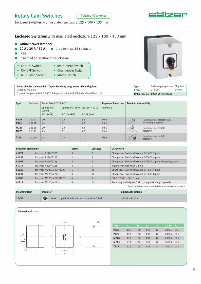
53
• Control Switch • Instrument Switch• ON-OFF Switch • Changeover Switch• Multi-step Switch • Motor Switch
Enclosed Switches with insulated enclosure 125 × 100 × 133 mm
without cover interlock 20 A / 25 A / 32 A 1 up to max. 16 contacts IP66 Insulated polycarbonate enclosure
Rotary Cam SwitchesEnclosed Switches with insulated enclosure 125 × 100 × 133 mm
Setup of order code number: Type - Switching programme - Mounting formOrdering example:4 pole Changeover Switch 90°, 25 A, padlockable with V-handle silver/black
Type Switching programme Mtg. form
P220 61154 276V1
Order code no. P220-61154-276V1
Type Contacts Rated data (IEC 60947) Degree of Protection Terminal accessibility
Operational current I
e
Operational power (at 380–440 V) Terminals
AC-21A (A) AC-23A (kW) AC-3A (kW)
P220P225
1 to 121 to 10
2025
7.511
5.57.5
IP66IP66
Terminals accessible frommounting direction
M220M225
1 to 161 to 12
2025
7.511
5.57.5
IP66IP66
Terminals accessiblelaterally
T225 1 to 10 32 15 11 IP66 Terminals accessiblelaterally
Switching programme Stages Contacts Description
61027 for types P220/P225 3 6 Changeover Switch with centre OFF 60°, 3 pole
61154 for types P220/P225 4 8 Changeover Switch with centre OFF 90°, 4 pole
61363 for types P220/P225 3 6 Changeover Switch with centre OFF 60°, 3 pole with spring return
61211 for types P220/P225 3 5 Motor Reversing Switch, 3 pole
61029 for types M220/M225/T225 5 10 Changeover Switch with centre OFF 60°, 5 pole
61032 for types M220/M225 8 16 Changeover Switch with centre OFF 60°, 8 pole
61008 for types M220/M225/T225 4 8 ON-OFF Switch 60°, 8 pole
61217 for types M220/M225 6 12 Reversing Multi-Speed Switch, single winding, 2 speeds
Dimensions in mm:
Type H1 B1 T1 T2 2 × M H2
P220 125 100 133 32 20/25 115
P225 125 100 133 32 20/25 115
M220 125 100 133 32 20/25 115
M225 125 100 133 32 20/25 115
T225 125 100 133 32 20/25 115
Switching diagrams and further switching programmes from page 56.
Mounting form Operator Padlockable options
276V1 padlockable with V-handle silver/black padlockable 12h
NS_engl.indb 53NS_engl.indb 53 14.09.2017 08:57:2114.09.2017 08:57:21
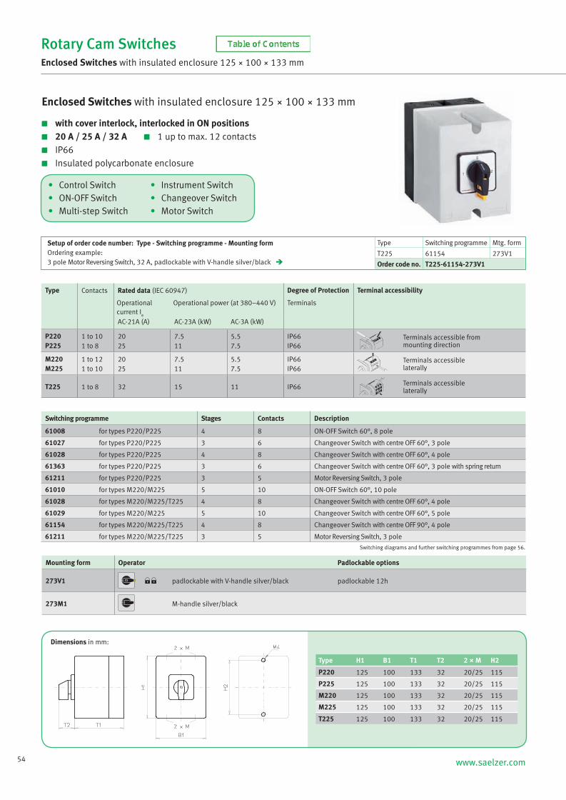
54 www.saelzer.com
• Control Switch • Instrument Switch• ON-OFF Switch • Changeover Switch• Multi-step Switch • Motor Switch
Enclosed Switches with insulated enclosure 125 × 100 × 133 mm
with cover interlock, interlocked in ON positions 20 A / 25 A / 32 A 1 up to max. 12 contacts IP66 Insulated polycarbonate enclosure
Rotary Cam SwitchesEnclosed Switches with insulated enclosure 125 × 100 × 133 mm
Setup of order code number: Type - Switching programme - Mounting formOrdering example:3 pole Motor Reversing Switch, 32 A, padlockable with V-handle silver/black
Type Switching programme Mtg. form
T225 61154 273V1
Order code no. T225-61154-273V1
Type Contacts Rated data (IEC 60947) Degree of Protection Terminal accessibility
Operational current I
e
Operational power (at 380–440 V) Terminals
AC-21A (A) AC-23A (kW) AC-3A (kW)
P220P225
1 to 101 to 8
2025
7.511
5.57.5
IP66IP66
Terminals accessible frommounting direction
M220M225
1 to 121 to 10
2025
7.511
5.57.5
IP66IP66
Terminals accessiblelaterally
T225 1 to 8 32 15 11 IP66 Terminals accessiblelaterally
Switching programme Stages Contacts Description
61008 for types P220/P225 4 8 ON-OFF Switch 60°, 8 pole
61027 for types P220/P225 3 6 Changeover Switch with centre OFF 60°, 3 pole
61028 for types P220/P225 4 8 Changeover Switch with centre OFF 60°, 4 pole
61363 for types P220/P225 3 6 Changeover Switch with centre OFF 60°, 3 pole with spring return
61211 for types P220/P225 3 5 Motor Reversing Switch, 3 pole
61010 for types M220/M225 5 10 ON-OFF Switch 60°, 10 pole
61028 for types M220/M225/T225 4 8 Changeover Switch with centre OFF 60°, 4 pole
61029 for types M220/M225 5 10 Changeover Switch with centre OFF 60°, 5 pole
61154 for types M220/M225/T225 4 8 Changeover Switch with centre OFF 90°, 4 pole
61211 for types M220/M225/T225 3 5 Motor Reversing Switch, 3 pole
Switching diagrams and further switching programmes from page 56.
Dimensions in mm:
Mounting form Operator Padlockable options
273V1 padlockable with V-handle silver/black padlockable 12h
273M1 M-handle silver/black
Type H1 B1 T1 T2 2 × M H2
P220 125 100 133 32 20/25 115
P225 125 100 133 32 20/25 115
M220 125 100 133 32 20/25 115
M225 125 100 133 32 20/25 115
T225 125 100 133 32 20/25 115
NS_engl.indb 54NS_engl.indb 54 14.09.2017 08:57:2214.09.2017 08:57:22

55
Enclosed Switches with insulated enclosure 125 × 100 × 133 mm
with cover interlock, interlocked in ON position 20 A / 25 A / 32 A 1 up to max. 12 contacts IP66 Insulated polycarbonate enclosure
Rotary Cam SwitchesEnclosed Switches with insulated enclosure 125 × 100 × 133 mm
Setup of order code number: Type - Switching programme - Mounting formOrdering example:6 pole ON-OFF Switch 90°, 20 A, padlock device with N-handle yellow/red
Type Switching programme Mtg. form
M220 61907 275N4
Order code no. M220-61907-275N4
Type Contacts Rated data (IEC 60947) Degree of Protection Terminal accessibility
Operational current I
e
Operational power (at 380–440 V) Terminals
AC-21A (A) AC-23A (kW) AC-3A (kW)
P220P225
1 to 101 to 8
2025
7.511
5.57.5
IP66IP66
Terminals accessible frommounting direction
M220M225
1 to 121 to 10
2025
7.511
5.57.5
IP66IP66
Terminals accessiblelaterally
T225 1 to 8 32 15 11 IP66 Terminals accessiblelaterally
Switching programme Stages Contacts Description
61919 for types P220/P225 4 8 ON-OFF Switch 90°, 8 pole, 2 pole early make/late break
61918 for types P220/P225 4 8 ON-OFF Switch 90°, 8 pole
61910 for type P220 5 10 ON-OFF Switch 90°, 10 pole
61907 for types M220/M225/T225 4 8 ON-OFF Switch 90°, 6 pole, 2 auxiliary contacts
61910 for types M220/M225 5 10 ON-OFF Switch 90°, 10 pole
• Main/Emergency-Off Switch• Main Switch
Switching diagrams and further switching programmes from page 56.
Dimensions in mm:
Mounting form H1 B1 T1 T2 2 × M H2
275N4/275N1 125 100 133 33 20/25 115
275M4/275M1 125 100 133 38 20/25 115
275V4/275V1 125 100 133 32 20/25 115
Mounting form Operator Main/Emergency-Off Switch Mounting form Operator Main Switch
275N4 padlock device with N-handleyellow/red 275N1
padlock device with N-handleblack
275M4 padlock device with M-handleyellow/red 275M1
padlock device with M-handleblack
275V4 padlockable with V-handleyellow/red 275V1
padlockable with V-handlesilver/black
NS_engl.indb 55NS_engl.indb 55 14.09.2017 08:57:2214.09.2017 08:57:22

56 www.saelzer.com
Rotary Cam Switches
Technical Information Switching programmes
Description Stages Contacts Ident No. Ident No. with inscription
ON-OFF Switches 90°
1 pole 2 pole 3 pole
3 pole with N/PE terminals 3 pole with N terminals 4 pole
4 pole, 1 pole early make/late break 4 pole, 3 pole early make/late break 5 pole, 3 pole early make/late break
6 pole 6 pole, 2 auxiliary contacts 7 pole 8 pole 8 pole, 2 pole early make/late break 9 pole10 pole12 pole
112
222
223
34
444 556
123
444
445
68
788
91012
61191.61192.61199.
61178.61908.61914.
61194.61904.61905.
61906.61907.
61917.61918.61919.
61909.61910.61912.
61...- 61...A 61...B 61...C 61...D 61...E
61...F 61...H 61...K
61...- 61...A 61...B
Description Stages Contacts Ident No. Ident No. with inscription
ON-OFF Switches 60°
1 pole 2 pole 3 pole
4 pole 5 pole 6 pole
7 pole 8 pole 9 pole
10 pole11 pole12 pole
112
233
445
566
123
456
789
101112
61001.61002.61003.
61004.61005.61006.
61007.61008.61009.
61010.61011.61012.
61...- 61...A 61...B 61...C 61...D 61...E
61...F 61...G 61...H 61...K 61...L
Description Stages Contacts Ident No. Ident No. with inscription
ON-OFF Switches with spring return
1122
1234
61351.61352.61353.61354.
61...- 61...A
61302- 61302A
Spring return to OFF 1 pole 2 pole 3 pole 4 pole
Spring return to ON 1 pole 1 1 61302.
Complete rotation 2 pole 3 pole
12
23
61198.61197.
NS_engl.indb 56NS_engl.indb 56 14.09.2017 08:57:2314.09.2017 08:57:23

57
Rotary Cam Switches
Technical Information Switching programmes
Description Stages Contacts Ident No. Ident No. with inscription
Changeover Switches with centre OFF, 60°
1 pole 2 pole 3 pole 4 pole
5 pole 6 pole 7 pole 8 pole
without jumpers 1 pole 2 pole 3 pole
1234
5678
123
2468
10121416
246
61025.61026.61027.61028.
61029.61030.61031.61032.
61625.61626.61627.
61...- 61...A 61...B 61...C 61...D 61...E
61...G 61...H 61...I 61...J 61...K 61...L
61...M 61...N 61...O 61...P 61...Q 61...R
61...S 61...T 61...U 61...V 61...W
Description Stages Contacts Ident No. Ident No. with inscription
Changeover Switches with centre OFF, 90°
1 pole 2 pole 3 pole 4 pole
1234
2468
61151.61152.61153.61154.
61...- 61...A 61...B 61...C 61...D 61...E
Description Stages Contacts Ident No. Ident No. with inscription
Changeover Switches with centre OFF and spring return
Spring return to centre 1 pole 2 pole 3 pole
without jumpers 1 pole 2 pole
123
12
246
24
61361.61362.61363.
61761.61762.
61...- 61...A 61...B 61...C 61...D 61...E
61...F 61...G 61...H 61...I 61...J 61...K
61...L 61...M 61...N 61...P 61...Q 61...R
61...S 61...T
NS_engl.indb 57NS_engl.indb 57 14.09.2017 08:57:2414.09.2017 08:57:24

58 www.saelzer.com
Rotary Cam Switches
Technical Information Switching programmes
Description Stages Contacts Ident No. Ident No. with inscription
Changeover Switches with centre OFF and spring return
Spring return from left to centre 1 pole 2 pole 3 pole
123
246
61364.61365.61369.
61...-
Description Stages Contacts Ident No. Ident No. with inscription
Changeover Switches without OFF
1 pole 2 pole 3 pole
4 pole 5 pole 6 pole
7 pole 8 pole 9 pole
10 pole11 pole12 pole
without jumpers 1 pole 2 pole 3 pole 4 pole
overlapping contacts 1 pole 2 pole 3 pole 4 pole
123
456
789
101112
1234
1234
246
81012
141618
202224
2468
2468
61037.61038.61039.
61040.61041.61042.
61043.61044.61045.
61046.61047.61048.
61637.61638.61639.61640.
61737.61738.61739.61740.
61...- 61...A 61...B 61...C 61...D 61...E
61...F 61...H 61...I
Description Stages Contacts Ident No. Ident No. with inscription
Changeover Switches without OFF with spring return
Spring return to left 1 pole 2 pole 3 pole
without jumpers 1 pole
123
1
246
2
61371.61372.61373.
61771.61...- 61...A 61...B 61...C 61...D 61...E
NS_engl.indb 58NS_engl.indb 58 14.09.2017 08:57:2414.09.2017 08:57:24

59
Rotary Cam Switches
Technical Information Switching programmes
Description Stages Contacts Ident No. Ident No. with inscription
Multi-step Switches with OFF
2 steps 1 pole 2 pole 3 pole
4 pole 5 pole 6 pole
123
456
246
81012
61059.61079.61099.
61130.61134.61137.
61...- 61...A 61...B
3 steps 1 pole 2 pole 3 pole
4 pole 5 pole
235
68
369
1215
61060.61080.61100.
61131.61135.
61...- 61...A 61...B 61...C 61...D
4 steps 1 pole 2 pole 3 pole 4 pole
2468
48
1216
61061.61081.61101.61132.
61...- 61...A
5 steps 1 pole 2 pole 3 pole
358
51015
61062.61082.61102.
61...- 61...A
6 steps 1 pole 2 pole 3 pole
369
61218
61063.61083.61103.
61...- 61...A
7 steps 1 pole 2 pole
47
714
61064.61084.
61...- 61...A
8 steps 1 pole 4 8 61065.
61065- 61065A
9 steps 1 pole 5 9 61066.
61066- 61066A
10 steps 1 pole 5 10 61067.
61067- 61067A
11 steps 1 pole 6 11 61068.
61068- 61068A
NS_engl.indb 59NS_engl.indb 59 14.09.2017 08:57:2514.09.2017 08:57:25

60 www.saelzer.com
Rotary Cam Switches
Technical Information Switching programmes
Description Stages Contacts Ident No. Ident No. with inscription
Multi-step Switches without OFF
3 steps 1 pole 2 pole 3 pole
4 pole 5 pole 6 pole
without jumpers 1 pole 2 pole
235
689
23
369
121518
36
61049.61069.61089.
61120.61124.61126.
61649.61669.
61...- 61...A
4 steps 1 pole 2 pole 3 pole
4 pole 5 pole 6 pole
without jumpers 1 pole 2 pole
246
81012
24
48
12
162024
48
61050.61070.61090.
61121.61125.61127.
61650.61670.
61...- 61...A
5 steps 1 pole 2 pole 3 pole 4 pole
358
10
5101520
61051.61071.61091.61122. 61...- 61...A
6 steps 1 pole 2 pole 3 pole
369
61218
61052.61072.61092.
61...- 61...A
7 steps 1 pole 2 pole 3 pole
47
11
71421
61053.61073.61093.
61...-
8 steps 1 pole 2 pole 3 pole
48
12
81624
61054.61074.61094.
61...-
9 steps 1 pole 5 9 61055.
61055-
10 steps 1 pole 5 10 61056.
61056-
11 steps 1 pole 6 11 61057.
61057-
12 steps 1 pole 6 12 61058.
61058-
NS_engl.indb 60NS_engl.indb 60 14.09.2017 08:57:2614.09.2017 08:57:26

61
Rotary Cam Switches
Technical Information Switching programmes
Description Stages Contacts Ident No. Ident No. with inscription
Code Switches
Binary code 0 - 7 0 - 7 complement 0 - 7 + complement
223
336
61920.61921.61922.
61...-
0 - 11 0 - 11 + complement
24
48
61923.61924.
61...-
BCD Code 0 - 9 0 - 9 complement 0 - 9 + complement
224
448
61930.61931.61932.
61...-
Description Stages Contacts Ident No. Ident No. with inscription
Gang Switches
2 gangs 1 pole 2 pole 3 pole
123
246
61109.61117.61111.
61...- 61...A 61...B
3 gangs 1 pole 2 pole 3 pole
Series-gang Switches2 gangs 1 pole 2 pole 3 pole
Series-parallel Switches2 gangs 2 pole
235
123
2
369
246
4
61110.61118.61112.
61113.61115.61114.
61116.
61...- 61...A
Description Stages Contacts Ident No. Ident No. with inscription
Voltmeter Selector Switches with OFF
3 phase line to line, 30° 2 4 61312.
61312- 61312A 61312B 61312C 61312D 61312E
61312F
3 phase line to line, 60° 2 4 61485.
61485- 61485A 6485B
NS_engl.indb 61NS_engl.indb 61 14.09.2017 08:57:2614.09.2017 08:57:26
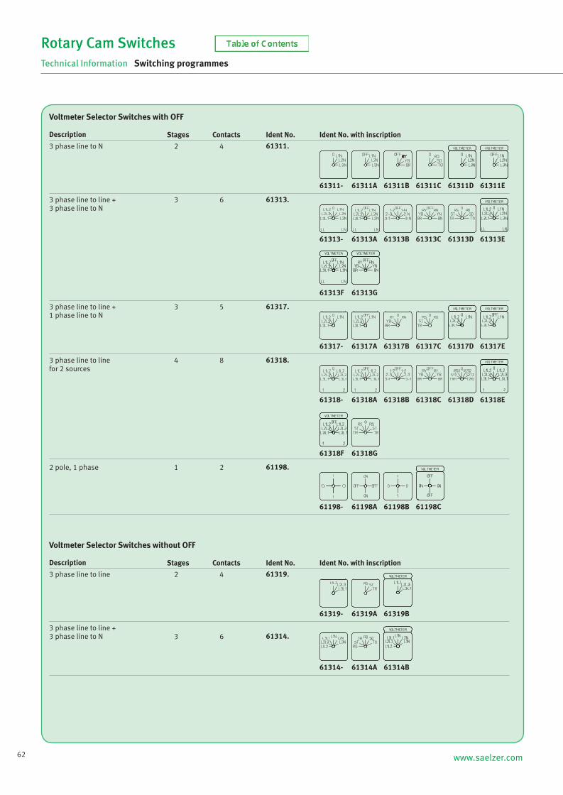
62 www.saelzer.com
Rotary Cam Switches
Technical Information Switching programmes
Description Stages Contacts Ident No. Ident No. with inscription
Voltmeter Selector Switches with OFF
3 phase line to N 2 4 61311.
61311- 61311A 61311B 61311C 61311D 61311E
3 phase line to line +3 phase line to N
3 6 61313.
61313- 61313A 61313B 61313C 61313D 61313E
61313F 61313G
3 phase line to line +1 phase line to N
3 5 61317.
61317- 61317A 61317B 61317C 61317D 61317E
3 phase line to line for 2 sources
4 8 61318.
61318- 61318A 61318B 61318C 61318D 61318E
61318F 61318G
2 pole, 1 phase 1 2 61198.
61198- 61198A 61198B 61198C
Description Stages Contacts Ident No. Ident No. with inscription
Voltmeter Selector Switches without OFF
3 phase line to line 2 4 61319.
61319- 61319A 61319B
3 phase line to line +3 phase line to N 3 6 61314.
61314- 61314A 61314B
NS_engl.indb 62NS_engl.indb 62 14.09.2017 08:57:2614.09.2017 08:57:26

63
Rotary Cam Switches
Technical Information Switching programmes
Description Stages Contacts Ident No. Ident No. with inscription
Ammeter Selector Switches with OFF
1 transformer, 1 pole 1 2 61321.
61321- 61321A 61321B 61321C 61321G
2 transformers, 1 pole (3 phase)3 transformers, 1 pole3 transformers, 2 pole
235
469
61331.61325.61328.
61...- 61...A 61...B 61...C 61...D 61...E
61...F
2 transformers, 2 pole 3 6 61327.
61327- 61327A 61327E
Description Stages Contacts Ident No. Ident No. with inscription
Ammeter Selector Switches without OFF
3 transformers, 1 pole3 transformers, 2 pole
35
69
61384.61329.
61...- 61...A
4 transformers, 1 pole4 transformers, 2 pole
46
812
61326.61330.
61...- 61...A
Description Stages Contacts Ident No. Ident No. with inscription
Volt-Ammeter Selector Switches
1 phase line to line,2 phase voltages L–N, 2 currents
4 8 61334.
61334- 61334A 61334B
3 voltages L–L, 3 currents3 phase voltages L–N, 3 currents
55
109
61336.61338.
61...- 61...A 61...B 61...C
61337- 61337A 61337B
4 voltages, 3 currents 6 11 61337.
NS_engl.indb 63NS_engl.indb 63 14.09.2017 08:57:2714.09.2017 08:57:27

64 www.saelzer.com
Rotary Cam Switches
Technical Information Switching programmes
Description Stages Contacts Ident No. Ident No. with inscription
Control Switches with spring return
Control Switches 1 pole 2 pole
without jumpers 1 pole
12
1
24
2
61300.61388.
61700. 61...- 61...A 61...B 61...C
Control Switcheswith position indication 1 pole
without jumpers 1 pole
1
1
2
2
61301.
61701. 61...- 61...A 61...B 61...C
Controlling two contactorsStandardwithout jumpers
22
33
61307.61707.
61...- 61...A 61...B
With spring return4 auxiliary contactsMotor voltage control switchsingle winding contactor
224
438
61366.61271.61272.
61...- 61...T
Description Stages Contacts Ident No. Ident No. with inscription
Motor Reversing Switches
2 pole 3 pole
23
45
61210.61211.
61...- 61...A 61...B
3 pole with spring return 3 5 61253.
61253- 61253T
Description Stages Contacts Ident No. Ident No. with inscription
Star-Delta Switches
StandardContact closed in “OFF”/“STOP”
45
89
61200.61239.
61...- 61...A 61...B 61...C
Spring return fromSTART to “OFF”
4 8 61201.
61201- 61201A
3 pole, complete rotation 3 5 61214.
61214- 61214A
NS_engl.indb 64NS_engl.indb 64 14.09.2017 08:57:2814.09.2017 08:57:28

65
Rotary Cam Switches
Technical Information Switching programmes
Description Stages Contacts Ident No. Ident No. with inscription
Star-Delta Switches
Description Stages Contacts Ident No. Ident No. with inscription
Multi-Speed Switches
2 speedssingle winding
single winding –contactor control2 separate windings
4
53
8
106
61212.
61215.61219. 61...- 61...A
2 speedssingle winding 4 8 61213.
61213- 61213A
3 speedsspeed 1+3 Dahlanderspeed 2+3 Dahlander
66
1111
61226.61243.
61...- 61...A
Reversing Multi-Speed Switches2 speeds, single winding 6 12 61217.
61217- 61217A 61217B
Description Stages Contacts Ident No. Ident No. with inscription
Auxiliary Phase Switches
Standard 2 3 61208.
61208- 61208A 61208B 61208C
2 directions 3 6 61209.
61209- 61209A 61209B
2 directionsphase continuously under load 3 6 61270.
61270- 61270A
61240- 61240A 61240B
for use with contactor 4 7 61240.
Reversing Star-Delta SwitchesStandard 5 10 61203.
61203- 61203A
NS_engl.indb 65NS_engl.indb 65 14.09.2017 08:57:2814.09.2017 08:57:28
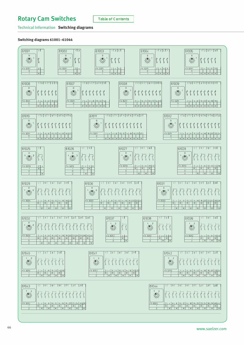
66 www.saelzer.com
Rotary Cam Switches
Technical Information Switching diagrams
Switching diagrams 61001–61044
NS_engl.indb 66NS_engl.indb 66 14.09.2017 08:57:2814.09.2017 08:57:28

67
Rotary Cam Switches
Technical Information Switching diagrams
Switching diagrams 61045–61062
NS_engl.indb 67NS_engl.indb 67 14.09.2017 08:57:2914.09.2017 08:57:29

68 www.saelzer.com
Rotary Cam Switches
Technical Information Switching diagrams
Switching diagrams 61063–61082
NS_engl.indb 68NS_engl.indb 68 14.09.2017 08:57:2914.09.2017 08:57:29
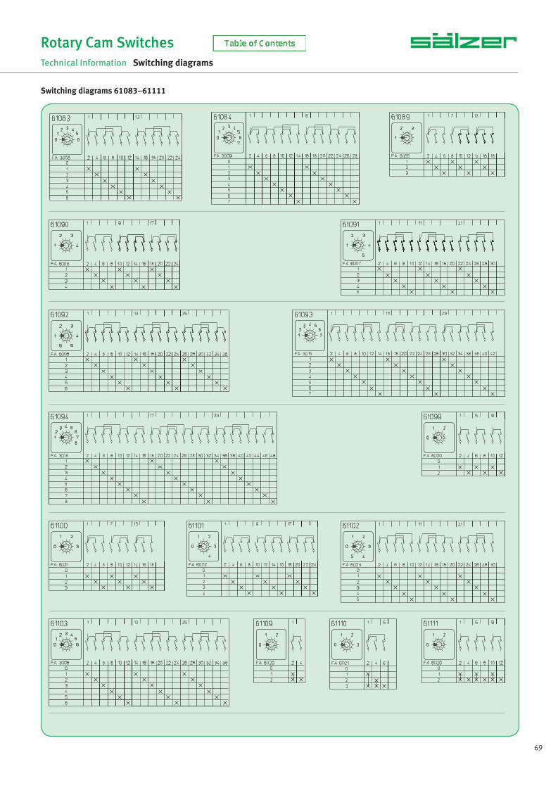
69
Rotary Cam Switches
Technical Information Switching diagrams
Switching diagrams 61083–61111
NS_engl.indb 69NS_engl.indb 69 14.09.2017 08:57:3014.09.2017 08:57:30

70 www.saelzer.com
Rotary Cam Switches
Technical Information Switching diagrams
Switching diagrams 61112–61137
NS_engl.indb 70NS_engl.indb 70 14.09.2017 08:57:3014.09.2017 08:57:30

71
Rotary Cam Switches
Technical Information Switching diagrams
Switching diagrams 61151–61215
NS_engl.indb 71NS_engl.indb 71 14.09.2017 08:57:3014.09.2017 08:57:30

72 www.saelzer.com
Rotary Cam Switches
Technical Information Switching diagrams
Switching diagrams 61217–61313
NS_engl.indb 72NS_engl.indb 72 14.09.2017 08:57:3014.09.2017 08:57:30
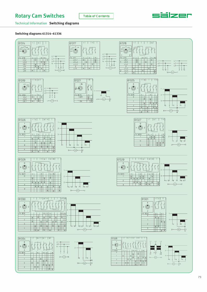
73
Rotary Cam Switches
Technical Information Switching diagrams
Switching diagrams 61314–61336
NS_engl.indb 73NS_engl.indb 73 14.09.2017 08:57:3114.09.2017 08:57:31

74 www.saelzer.com
Rotary Cam Switches
Technical Information Switching diagrams
Switching diagrams 61337–61707
NS_engl.indb 74NS_engl.indb 74 14.09.2017 08:57:3114.09.2017 08:57:31

75
Rotary Cam Switches
Technical Information Switching diagrams
Switching diagrams 61737–61932
Order form for rotary cam switches with special switching programmes page 88.
NS_engl.indb 75NS_engl.indb 75 14.09.2017 08:57:3214.09.2017 08:57:32

76 www.saelzer.com
Rotary Cam Switches
Technical Information Legend plates
2 switch positions
45° switching angle
FA 6001 FA 6002 FA 6018 FA 6025 FA 6026 FA 6027 FA 6028 FA 6029 FA 6030 FA 6033 FA 6051
FA 4018 FA 4020 FA 4022 FA 4047 FA 4048 FA 4052 FA 4054 FA 4055 FA 4056 FA 4066 FA 4073
FA 4077 FA 4078 FA 4080
60° switching angle
FA 6053 FA 6055 FA 6056 FA 6057 FA 6058 FA 6129 FA 6134 FA 6135 FA 6140 FA 6149
FA 9011 FA 9016 FA 9017 FA 9018 FA 9021 FA 9026 FA 9031 FA 9032 FA 9033 FA 9057 FA 9058
90° switching angle
FA 9078 FA 9079 FA 9080
3 switch positions
30° switching angle
FA 3028 FA 3030 FA 3046 FA 3103 FA 3104 FA 3105 FA 3106 FA 3116 FA 3117 FA 3118 FA 3119
FA 3120 FA 3121
NS_engl.indb 76NS_engl.indb 76 14.09.2017 08:57:3214.09.2017 08:57:32
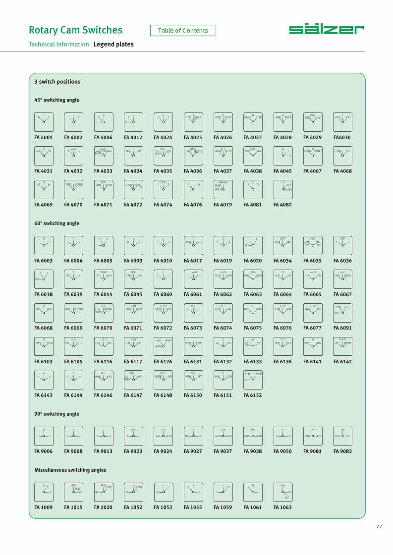
77
Rotary Cam Switches
Technical Information Legend plates
45° switching angle
FA 4001 FA 4002 FA 4006 FA 4012 FA 4024 FA 4025 FA 4026 FA 4027 FA 4028 FA 4029 FA4030
FA 4031 FA 4032 FA 4033 FA 4034 FA 4035 FA 4036 FA 4037 FA 4038 FA 4045 FA 4067 FA 4068
FA 4069 FA 4070 FA 4071 FA 4072 FA 4074 FA 4076 FA 4079 FA 4081 FA 4082
3 switch positions
60° switching angle
FA 6003 FA 6004 FA 6005 FA 6009 FA 6010 FA 6017 FA 6019 FA 6020 FA 6034 FA 6035 FA 6036
FA 6038 FA 6039 FA 6044 FA 6045 FA 6060 FA 6061 FA 6062 FA 6063 FA 6064 FA 6065 FA 6067
FA 6068 FA 6069 FA 6070 FA 6071 FA 6072 FA 6073 FA 6074 FA 6075 FA 6076 FA 6077 FA 6091
FA 6103 FA 6105 FA 6116 FA 6117 FA 6126 FA 6131 FA 6132 FA 6133 FA 6136 FA 6141 FA 6142
FA 6143 FA 6144 FA 6146 FA 6147 FA 6148 FA 6150 FA 6151 FA 6152
90° switching angle
FA 9006 FA 9008 FA 9013 FA 9023 FA 9024 FA 9027 FA 9037 FA 9038 FA 9050 FA 9081 FA 9083
Miscellaneous switching angles
FA 1009 FA 1015 FA 1020 FA 1052 FA 1053 FA 1055 FA 1059 FA 1061 FA 1063
NS_engl.indb 77NS_engl.indb 77 14.09.2017 08:57:3314.09.2017 08:57:33

78 www.saelzer.com
Rotary Cam Switches
Technical Information Legend plates
4 switch positions
30° switching angle
FA 3014 FA 3021 FA 3022 FA 3029 FA 3047 FA 3056 FA 3058 FA 3087 FA 3088 FA 3089 FA 3090
FA 3107 FA 3108 FA 3109 FA 3110
45° switching angle
FA 4007 FA 4013 FA 4075 FA 4083 FA 4084 FA 4085
60° switching angle
FA 6006 FA 6013 FA 6021 FA 6041 FA 6049 FA 6104 FA 6113 FA 6114 FA 6119 FA 6127 FA 6137
FA 6138 FA 6145 FA 6153
90° switching angle
FA 9004 FA 9005 FA 9007 FA 9009 FA 9010 FA 9014 FA 9015 FA 9019 FA 9020 FA 9025 FA9028
FA 9029 FA 9034 FA 9035 FA 9039 FA 9046 FA 9047 FA 9048 FA 9049 FA 9052 FA 9060 FA 9082
FA 9084
FA 1017 FA 1022 FA 1056 FA 1057
Miscellaneous switching angles
NS_engl.indb 78NS_engl.indb 78 14.09.2017 08:57:3414.09.2017 08:57:34

79
Rotary Cam Switches
Technical Information Legend plates
30° switching angle
FA 3006 FA 3031 FA 3033 FA 3034 FA 3048 FA 3063 FA 3064 FA 3092 FA 3093 FA 3111 FA 3112
5 switch positions
45° switching angle
FA 4003 FA 4008 FA 4014 FA 4039 FA 4040 FA 4041 FA 4059 FA 4060
60° switching angle
FA 6007 FA 6011 FA 6014 FA 6022 FA 6037 FA 6042 FA 6046 FA 6078 FA 6139
Miscellaneous switching angles
FA 1007 FA 1008 FA 1011 FA 1014 FA 1018 FA 1019 FA 1054 FA 1058 FA 1060 FA 1062
6 switch positions
30° switching angle
FA 3007 FA 3032 FA 3049 FA 3100 FA 3113 FA 3122
45° switching angle
FA 4009 FA 4015 FA 4091
NS_engl.indb 79NS_engl.indb 79 14.09.2017 08:57:3414.09.2017 08:57:34

80 www.saelzer.com
Rotary Cam Switches
Technical Information Legend plates
60° switching angle
FA 6008 FA 6012 FA 6015 FA 6023 FA 6024 FA 6040 FA 6043 FA 6047 FA 6081 FA 6083 FA 6085
FA 6098 FA 6118
30° switching angle
FA 3004 FA 3008 FA 3015 FA 3023 FA 3035 FA 3043 FA 3050 FA 3060 FA 3062 FA 3065 FA 3067
7 switch positions
FA 3082 FA 3083 FA 3084 FA 3114 FA 3115
6 switch positions
45° switching angle
FA 4004 FA 4010 FA 4016 FA 4086 FA 4087 FA 4088 FA 4089 FA 4090
30° switching angle
FA 3009 FA 3016 FA 3051
8 switch positions
45° switching angle
FA 4011 FA 4017 FA 4046 FA 4058 FA 4061 FA 4092
NS_engl.indb 80NS_engl.indb 80 14.09.2017 08:57:3514.09.2017 08:57:35

81
Rotary Cam Switches
Technical Information Legend plates
30° switching angle
FA 3010 FA 3017 FA 3025 FA 3044 FA 3052
9 switch positions
30° switching angle
FA 3011 FA 3018 FA 3053
10 switch positions
30° switching angle
FA 3012 FA 3019 FA 3054
11 switch positions
30° switching angle
FA 3013 FA 3020 FA 3055 FA 3123
12 switch positions
Other
FA 1001
NS_engl.indb 81NS_engl.indb 81 14.09.2017 08:57:3514.09.2017 08:57:35

82 www.saelzer.com
Rotary Cam Switches
Technical Information Legend plates
FA 8000 FA 8001 FA 8002 FA 8003 FA 8004 FA 8005
FA 8006 FA 8007 FA 8008 FA 8009 FA 8010 FA 8011
FA 8012 FA 8013 FA 8014 FA 8015 FA 8016 FA 8017
FA 8018 FA 8019 FA 8021 FA 8023 FA 8024 FA 8025
FA 8026 FA 8027 FA 8028 FA 8029 FA 8030 FA 8031
FA 8032 FA 8033 FA 8034 FA 8035 FA 8036 FA 8037
FA 8038 FA 8039 FA 8040 FA 8041 FA 8042 FA 8044
Standard escutcheon 30 × 30 mm Order code numberLegend plate silver, inscription black FAS1-…. (+FA number)Legend plate yellow, inscription black FBS1-…. (+FA number)Legend plate black, inscription silver FCS1-…. (+FA number)Legend plate white, inscription black FDS1-…. (+FA number)Legend plate black, inscription white FES1-…. (+FA number)
How to order legend plates
Standard escutcheon 48 × 48 mm Order code numberLegend plate silver, inscription black FAS2-…. (+FA number)Legend plate yellow, inscription black FBS2-…. (+FA number)Legend plate black, inscription silver FCS2-…. (+FA number)Legend plate white, inscription black FDS2-…. (+FA number)Legend plate black, inscription white FES2-…. (+FA number)
Standard escutcheon 64 × 64 mm Order code numberLegend plate silver, inscription black FAS4-…. (+FA number)Legend plate yellow, inscription black FBS4-…. (+FA number)Legend plate black, inscription silver FCS4-…. (+FA number)Legend plate white, inscription black FDS4-…. (+FA number)Legend plate black, inscription white FES4-…. (+FA number)
Standard escutcheon 88 × 88 mm Order code numberLegend plate silver, inscription black FAS6-…. (+FA number)Legend plate yellow, inscription black FBS6-…. (+FA number)Legend plate black, inscription silver FCS6-…. (+FA number)Legend plate white, inscription black FDS6-…. (+FA number)Legend plate black, inscription white FES6-…. (+FA number)
Standard escutcheon 130 × 130 mm Order code numberLegend plate silver, inscription black FAS8-…. (+FA number)Legend plate yellow, inscription black FBS8-…. (+FA number)Legend plate black, inscription silver FCS8-…. (+FA number)Legend plate white, inscription black FDS8-…. (+FA number)Legend plate black, inscription white FES8-…. (+FA number)
Additional top escutcheon plates Order code numberLegend plate silver, inscription black FAS2-8… (+FA number)Legend plate yellow, inscription black FBS2-8… (+FA number)Legend plate black, inscription silver FCS2-8… (+FA number)Legend plate white, inscription black FDS2-8… (+FA number)Legend plate black, inscription white FES2-8… (+FA number)
FA 8045 FA 8046 FA 8047
Additional top escutcheon plates
Order form for Rotary cam switches with special inscriptions page 90.
NS_engl.indb 82NS_engl.indb 82 14.09.2017 08:57:3614.09.2017 08:57:36

83
Rotary Cam Switches
Technical Information Accessories
Additional top escutcheon plateswith additional inscription to be clipped on the escutcheons and padlock devices Order code number Escutcheon frame plate black, legend plate silver, without inscription (can be engraved) FAZ2 - 8000Escutcheon frame plate black, legend plate silver, inscription black, inscription FA 8… (see page 82) FAZ2 - 8… Escutcheon frame plate black, legend plate silver, inscription black, special engraving FAZ2 - (special no.)
Escutcheon frame plate black, legend plate yellow, without inscription (can be engraved) FBZ2 - 8000Escutcheon frame plate black, legend plate yellow, inscription black, inscription FA 8… (see page 82) FBZ2 - 8Escutcheon frame plate black, legend plate yellow, inscription black, special engraving FBZ2 - (special no.)
Escutcheon frame plate black, legend plate black, without inscription (can be engraved) FCZ2 - 8000Escutcheon frame plate black, legend plate black, inscription silver, inscription FA 8… (see page 82) FCZ2 - 8… Escutcheon frame plate black, legend plate black, inscription silver, special engraving FCZ2 - (special no.)
Escutcheon frame plate black, legend plate white, without inscription (can be engraved) FDZ2 - 8000Escutcheon frame plate black, legend plate white, inscription black, inscription FA 8… (see page 82) FDZ2 - 8… Escutcheon frame plate black, legend plate white, inscription black, special engraving FDZ2 - (special no.)
Escutcheon frame plate black, legend plate black, without inscription (can be engraved) FEZ2 - 8000Escutcheon frame plate black, legend plate black, inscription white, inscription FA 8… (see page 82) FEZ2 - 8… Escutcheon frame plate black, legend plate black, inscription white, special engraving FEZ2 - (special no.)
Escutcheon frame plate black (without legend plate) FAZ2
Legend plates for additional top escutcheon plates
Legend plate silver, without inscription (can be engraved) FAS2 - 8000 Legend plate silver, inscription black, inscription FA 8… (see page 82) FAS2 - 8…Legend plate silver, inscription black, special engraving FAS2 - (special no.)
Legend plate yellow, without inscription (can be engraved) FBS2 - 8000Legend plate yellow, inscription black, inscription FA 8… (see page 82) FBS2 - 8…Legend plate yellow, inscription black, special engraving FBS2 - (special no.)
Legend plate black, without inscription (can be engraved) FCS2 - 8000Legend plate black, inscription silver, inscription FA 8… (see page 82) FCS2 - 8…Legend plate black, inscription silver, special engraving FCS2 - (special no.)
Legend plate white, without inscription (can be engraved) FDS2 - 8000Legend plate white, inscription black, inscription FA 8… (see page 82) FDS2 - 8…Legend plate white, inscription black, special engraving FDS2 - (special no.)
Legend plate black, inscription white, inscription FA 8… (see page 82) FES2 - 8…Legend plate black, inscription white, special engraving FES2 - (special no.)
suitable for the fast assembly of escutcheons and padlock devices
Types Order code number
P110 / P220 / P225 / M220 / M225 / T225 218098
Assembly tool for single hole mounting
FAZ2-8041 218098
Additional top escutcheon plates/Assembly tool
NS_engl.indb 83NS_engl.indb 83 14.09.2017 08:57:3614.09.2017 08:57:36

84 www.saelzer.com
Rotary Cam Switches
Technical Information Accessories
Cmin Cmax number Order code number
42 mm 59 mm – 60 mm 84 mm 185 mm 109 mm 2110 mm 134 mm 3135 mm 159 mm 4160 mm 184 mm 5185 mm 209 mm 6
–AVD2AVD2AVD2AVD2AVD2AVD2
AVD2 AVC2-.
Door clutch
42 mm 57 mm –64 mm 82 mm 189 mm 107 mm 1114 mm 132 mm 1139 mm 157 mm 1164 mm 182 mm 1189 mm 207 mm 1
–AVC2 - 1AVC2 - 2AVC2 - 3AVC2 - 4AVC2 - 5AVC2 - 6
Door interlock
Modular shaft extensions for mounting forms with door clutch or door interlock
Please note: AVC-2 to AVC2-6 have additional parts to aid the stability of the extended shaft modules
Shaft extensions
NS_engl.indb 84NS_engl.indb 84 14.09.2017 08:57:3614.09.2017 08:57:36

85
Rotary Cam Switches
Technical Information Key removable positions
The dot in the order code number must be replaced by the classifi cation letter which identifi es the key removable positions.Due to the construction of the locking cylinder the key can also be removed at 180 degrees of the designated position.
A
B
C
D
E
F
L
M
N
O
P
R
S
key removable at 09 h / 03 h
key removable at 12 h / 06 h
key removable at09 h / 12 h / 03 h / 06 h
key removable at 09 h / 11 h / 01 h / 03 h / 05 h / 07 h
key removable at 10 h / 04 h
key removable at02 h / 08 h
key removable at11 h / 05 h
key removable at01 h / 07 h
key removable at10 h / 12 h / 02 h / 04 h / 06 h / 08 h
key removable at11 h / 01 h / 05 h / 07 h
key removable at10 h / 12 h / 04 h / 06 h
key removable at12 h / 02 h / 06 h / 08 h
key removable at10 h / 02 h / 04 h / 08 h
Type P110
Standard cylinder lock L001. Other lock types on request.
A
B
C
D
E
F
G
H
J
K
L
M
N
O
P
R
S
key removable at 09 h / 03 h
key removable at 12 h / 06 h
key removable at09 h / 12 h / 03 h / 06 h
key removable at 09 h / 11 h / 01 h / 03 h / 05 h / 07 h
key removable at 10 h / 04 h
key removable at02 h / 08 h
key removable at09 h / 10.30 h / 12 h / 01.30 h / 03 h / 04.30 h / 06 h / 07.30 h
key removable at10.30 h / 04.30 h
key removable at01.30 h / 07.30 h
key removable at10.30 h / 12 h / 04.30 h / 06 h
key removable at 09 h / 10 h / 11 h / 12 h / 01 h / 02 h / 03 h / 04 h / 05 h / 06 h / 07 h / 08 h
key removable at11 h / 05 h
key removable at01 h / 07 h
key removable at10 h / 12 h / 02 h / 04 h / 06 h / 08 h
key removable at11 h / 01 h / 05 h / 07 h
key removable at10 h / 12 h / 04 h / 06 h
key removable at12 h / 02 h / 06 h / 08 h
key removable at10 h / 02 h / 04 h / 08 h
Types P220 / P225 / M220 / M225 / T225
Standard cylinder lock C001. Other lock types on request.
Tkey removable at09 h / 10.30 h / 03 h / 04.30 h
U
NS_engl.indb 85NS_engl.indb 85 14.09.2017 08:57:3614.09.2017 08:57:36

86 www.saelzer.com
Rotary Cam Switches
Technical Information Operators
Operator variants for mounting forms with escutcheon and handle
Operator Colour Colour Colour Change ofSuitable for Types escutcheon legend plate operator order code number
black silver black .... - ..... - ...M1 grey silver grey .... - ..... - ...M2 white silver white .... - ..... - ...M3 black yellow red .... - ..... - ...M4 black silver red .... - ..... - ...M5 black black black .... - ..... - ...M8
black silver black .... - ..... - ...F1 grey silver grey .... - ..... - ...F2 white silver white .... - ..... - ...F3 black yellow red .... - ..... - ...F4 black silver red .... - ..... - ...F5 black black black .... - ..... - ...F8
black silver black .... - ..... - ...B1 grey silver grey .... - ..... - ...B2 white silver white .... - ..... - ...B3 black yellow red .... - ..... - ...B4 black silver red .... - ..... - ...B5 black black black .... - ..... - ...B8
black silver black .... - ..... - ...N1 grey silver grey .... - ..... - ...N2 white silver white .... - ..... - ...N3 black yellow red .... - ..... - ...N4 black silver red .... - ..... - ...N5 black black black .... - ..... - ...N8
black silver black .... - ..... - ...G1 black yellow red .... - ..... - ...G4 black silver red .... - ..... - ...G5 black black black .... - ..... - ...G8
black silver black .... - ..... - ...R1 grey silver grey .... - ..... - ...R2 white silver white .... - ..... - ...R3 black yellow red .... - ..... - ...R4 black silver red .... - ..... - ...R5
Installation mounting for 45 mm aperture in Panel/Distribution boards:
grey silver black .... - ..... - ...M1 grey silver grey .... - ..... - ...M2 grey yellow red .... - ..... - ...M4
grey silver black .... - ..... - ...N1 grey silver grey .... - ..... - ...N2 grey yellow red .... - ..... - ...N4
M-handle
P110, P220, P225,M220, M225, T225,S432, S440,S606, S608, S612
F-handle
P220, P225,M220, M225,T225
B-handle
P220, P225,M220, M225, T225,S432, S440,S606, S608, S612, S825
N-handle
P220, P225,M220, M225,T225,S432, S440
G-handle
S432, S440,S606, S608, S612,S825
R-handle
P220, P225,M220, M225,T225,S432, S440
N-handle
P220, P225,M220, M225,T225
M-handle
P220, P225,M220, M225T225
NS_engl.indb 86NS_engl.indb 86 14.09.2017 08:57:3714.09.2017 08:57:37

87
Rotary Cam Switches
Technical Information Operators
Operator variants for mounting forms with padlock device
Operator Colour Colour Colour Change ofSuitable for Types escutcheon legend plate operator order code number
black white black .... - ..... - ...N1 grey white grey .... - ..... - ...N2 yellow white red .... - ..... - ...N4 grey white black .... - ..... - ...N6 yellow white black .... - ..... - ...N7
black white black .... - ..... - ...M1 grey white grey .... - ..... - ...M2 yellow white red .... - ..... - ...M4 grey white black .... - ..... - ...M6 yellow white black .... - ..... - ...M7
black silver black .... - ..... - ...B1 black yellow red .... - ..... - ...B4
black black black .... - ..... - ...B8
black silver black .... - ..... - ...H1 black yellow red .... - ..... - ...H4 black black black .... - ..... - ...H8
black silver black .... - ..... - ...V1 black yellow red .... - ..... - ...V4
black silver black .... - ..... - ...L1 black yellow red .... - ..... - ...L4
N-padlock device
P220, P225,M220, M225,T225,S432, S440,S606, S608, S612
Installation mounting for 45 mm aperture in Panel/Distribution boards:
grey silver black .... - ..... - ...V1 grey yellow red .... - ..... - ...V4
grey silver black .... - ..... - ...L1 grey yellow red .... - ..... - ...L4
M-padlock device
P110,P220, P225,M220, M225,T225,S432, S440,S606, S608, S612
B-padlock device
S432, S440,S606, S608, S612,S825
H-padlock device
S432, S440,S606, S608, S612,S825
Padlockable with V-handle
P110, P220, P225,M220, M225, T225,S432, S440
Padlockable with V-handle
P220, P225,M220, M225T225
operator external dimension max. number of padlocks hasp diameter of padlock67 × 67 mm 3 4 mm (min) / 8 mm (max)88 × 88 mm 4 5 mm (min) / 9 mm (max)
operator external dimension max. number of padlocks hasp diameter of padlock48 × 48 mm 3 3 mm (min) / 5 mm (max)67 × 67 3 4 mm (min) / 8 mm (max)88 × 88 mm 4 5 mm (min) / 9 mm (max)
operator external dimension max. number of padlocks hasp diameter of padlock75 × 114 mm 4 5 mm (min) / 8 mm (max)98 × 142 4 5 mm (min) / 8 mm (max)130 × 178 mm 4 5 mm (min) / 8 mm (max)
operator external dimension max. number of padlocks hasp diameter of padlock75 × 114 mm 4 5 mm (min) / 8 mm (max)98 × 142 4 5 mm (min) / 8 mm (max)130 × 178 mm 4 5 mm (min) / 8 mm (max)
operator external dimension max. number of padlocks hasp diameter of padlock48 × 48 mm 2 3 mm (min) / 5 mm (max)64 × 64 mm 3 4 mm (min) / 6 mm (max)
operator external dimension max. number of padlocks hasp diameter of padlock
45 × 52.5 mm 2 3 mm (min) / 5 mm (max)
Padlockable with L-handle
P110, P220, P225,M220, M225,T225
operator external dimension max. number of padlocks hasp diameter of padlock
48 × 48 mm 2 3 mm (min) / 5 mm (max)
Padlockable with L-handle
P220, P225,M220, M225,T225
operator external dimension max. number of padlocks hasp diameter of padlock
45 × 52.5 mm 2 3 mm (min) / 5 mm (max)
NS_engl.indb 87NS_engl.indb 87 14.09.2017 08:57:3814.09.2017 08:57:38

88 www.saelzer.com
Rotary Cam Switches
Technical Information Special switches
Special switching programmes can be produced by means of prefabricated modules either by us or by our authorized workshops all over the world.
For description of the desired course of switching please use our form on page 89. In case of more than 18 contacts an additional form can be used as page 2.
When determining the desired switch the following has to be considered:
· Indicate terminal designations at connection points only and use fi gures, if possible.
· Mark initial position and/or “OFF” position on the handle with an arrow.
· Mark escutcheon engraving on the escutcheon and indicate it in the column “Switch positions”. In the case of special engraving if the space is not suffi cient, use the form for special legend plates (refer to page 91) or enclose a sketch.
· Determine the desired switching angle. If necessary due to technical reasons we may suggest a different switching angle.
· The column “locked positions” is to be fi lled in only in case of interlockings (e.g. key removable position) and locking mechanisms.
· At the bottom of the order form 6 areas are identifi ed (1 to 6). Areas 1 to 3 must always be specifi ed. Areas 4 to 6 have to be completed in case of deviations from the standard equipment of the design and/or upon demand. Area 7 “Order code no.” is specifi ed on your fi rst order. For all subsequent orders the indication of this order code number is suffi cient.
Ordering example
How to order special switches
NS_engl.indb 88NS_engl.indb 88 14.09.2017 08:57:3814.09.2017 08:57:38

89
Rotary Cam Switches
Technical Information Special switches
Copy form for special switches
NS_engl.indb 89NS_engl.indb 89 14.09.2017 08:57:3814.09.2017 08:57:38
90 www.saelzer.com
Rotary Cam Switches
Technical Information Special engravings
For descriptions of the desired special engraving please use our order forms. On page 91 you will fi nd order forms for switches with switching angle 30°/ 60° and 45°/ 90°.
When determining the desired engraving the following has to be considered:
· For standard engraving capital letters or fi gures type Helvetica in black are used.
· Engravings deviating from the standard design like small size text, symbols or graphical symbols please enclose a drawing or a fi le.
· The max. quantity of letters (symbols) is specifi ed in the order form.
· The max. letter height is for escutcheon 30 mm = 3.5 mm escutcheon 48 mm = 4.0 mm escutcheon 64 mm = 4.5 mm escutcheon 88 mm = 6.5 mm escutcheon 130 mm = 8.0 mm
When utilizing the max. letter (symbol) quantity the letter height might be reduced.
· With the fi rst order a FAX no. for the legend plate and a FAZ no. for the additional legend plate is fi xed for every special engraving that will remain valid for all subsequent orders.
How to order special engravings
NS_engl.indb 90NS_engl.indb 90 14.09.2017 08:57:3814.09.2017 08:57:38

91
Rotary Cam Switches
Technical Information Special engravings
Copy form for special engravings
NS_engl.indb 91NS_engl.indb 91 14.09.2017 08:57:3814.09.2017 08:57:38

92 www.saelzer.com
Rotary Cam Switches
Technical Information Utilisation Categories
Utilisation Categories
Utilisation categories for Switches, Disconnectors, Switch-Disconnectors and Fuse-Combination Units according to IEC/EN 60947-3
Type of Current Utilisation Category Typical applications Frequent Occasional operation operation
AC AC-15A AC-15B Controlling electromagnetic load
AC-20A * AC-20B * Making and breaking without load
AC-21A AC-21B Switching resistive loads including low overloads
AC-22A AC-22B Switching mixed resistive and inductive loads, including low overloads AC-23A AC-23B Switching motors and other highly inductive loads
DC DC-20A * DC-20B * Making and breaking without load
DC-21A DC-21B Switching resistive loads including low overloads
DC-22A DC-22B Switching mixed resistive and inductive loads, including low overloads (e. g. shunt motors)
DC-23A DC-23B Switching highly inductive loads (e. g. series motors)
* The application of these utilisation categories isn't permitted in the USA.
Category AC-23 includes occasional switching of individual motors. The utilisation categories in the above table do not apply to an equipment normally used to start, accelerate and/or stop individual motors. The utilisation categories for such an equipment are dealt with the following table:
Type of Current Utilisation Category Typical applications
AC AC-2 Slip-ring motors: starting, plugging1), switching off
AC-3 Squirrel-cage motors: starting, switching off running motors
AC-4 Squirrel-cage motors: starting, plugging1), inching 2)
DC DC-3 Shunt motors: starting, plugging1), inching 2), dynamic breaking of d.c. motors
DC-4 Series motors: starting, plugging1), inching 2), dynamic breaking of d.c. motors
1) Plugging is understood to mean stopping or reversing the motor rapidly by reversing motor primary connections while the motor is running.
2) Inching (jogging) is understood to mean energizing a motor once or repeatedly for short periods to obtain small movements of the driven mechanism.
Note: The switching of rotor circuits, capacitors or tungsten fi lament/discharge lamps shall be subject to special agreements between manufacturer and user.
NS_engl.indb 92NS_engl.indb 92 14.09.2017 08:57:3814.09.2017 08:57:38
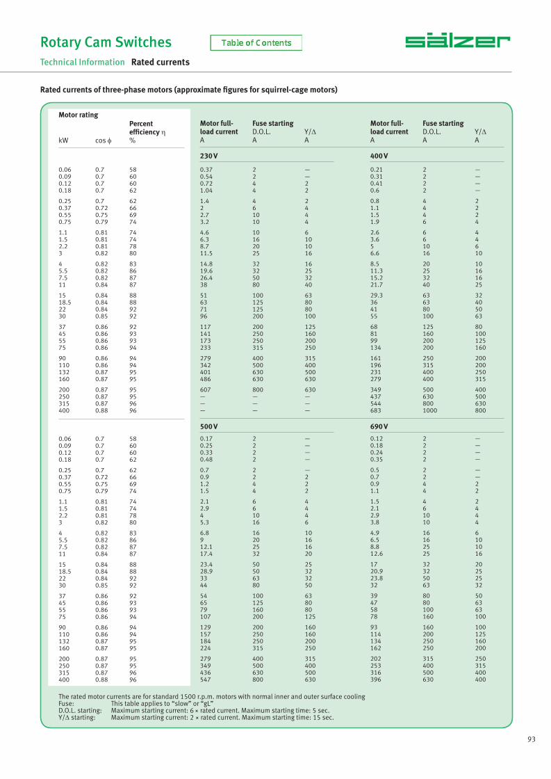
93
Rotary Cam Switches
Technical Information Rated currents
Rated currents of three-phase motors (approximate fi gures for squirrel-cage motors)
0.06 0.7 580.09 0.7 600.12 0.7 600.18 0.7 62
0.25 0.7 620.37 0.72 660.55 0.75 690.75 0.79 74
1.1 0.81 741.5 0.81 742.2 0.81 783 0.82 80
4 0.82 835.5 0.82 867.5 0.82 8711 0.84 87
15 0.84 8818.5 0.84 8822 0.84 9230 0.85 92
37 0.86 9245 0.86 9355 0.86 9375 0.86 94
90 0.86 94110 0.86 94132 0.87 95160 0.87 95
200 0.87 95250 0.87 95315 0.87 96400 0.88 96
0.37 2 —0.54 2 —0.72 4 21.04 4 2
1.4 4 22 6 42.7 10 43.2 10 4
4.6 10 66.3 16 108.7 20 1011.5 25 16
14.8 32 1619.6 32 2526.4 50 3238 80 40
51 100 6363 125 8071 125 8096 200 100
117 200 125141 250 160173 250 200233 315 250
279 400 315342 500 400401 630 500486 630 630
607 800 630— — —— — —— — —
0.21 2 —0.31 2 —0.41 2 —0.6 2 —
0.8 4 21.1 4 21.5 4 21.9 6 4
2.6 6 43.6 6 45 10 66.6 16 10
8.5 20 1011.3 25 1615.2 32 1621.7 40 25
29.3 63 3236 63 4041 80 5055 100 63
68 125 8081 160 10099 200 125134 200 160
161 250 200196 315 200231 400 250279 400 315
349 500 400437 630 500544 800 630683 1000 800
0.17 2 —0.25 2 —0.33 2 —0.48 2 —
0.7 2 —0.9 2 21.2 4 21.5 4 2
2.1 6 42.9 6 44 10 45.3 16 6
6.8 16 109 20 1612.1 25 1617.4 32 20
23.4 50 2528.9 50 3233 63 3244 80 50
54 100 6365 125 8079 160 80107 200 125
129 200 160157 250 160184 250 200224 315 250
279 400 315349 500 400436 630 500547 800 630
0.12 2 —0.18 2 —0.24 2 —0.35 2 —
0.5 2 —0.7 2 —0.9 4 21.1 4 2
1.5 4 22.1 6 42.9 10 43.8 10 4
4.9 16 66.5 16 108.8 25 1012.6 25 16
17 32 2020.9 32 2523.8 50 2532 63 32
39 80 5047 80 6358 100 6378 160 100
93 160 100114 200 125134 250 160162 250 200
202 315 250253 400 315316 500 400396 630 400
230 V 400 V
500 V 690 V
0.06 0.7 580.09 0.7 600.12 0.7 600.18 0.7 62
0.25 0.7 620.37 0.72 660.55 0.75 690.75 0.79 74
1.1 0.81 741.5 0.81 742.2 0.81 783 0.82 80
4 0.82 835.5 0.82 867.5 0.82 8711 0.84 87
15 0.84 8818.5 0.84 8822 0.84 9230 0.85 92
37 0.86 9245 0.86 9355 0.86 9375 0.86 94
90 0.86 94110 0.86 94132 0.87 95160 0.87 95
200 0.87 95250 0.87 95315 0.87 96400 0.88 96
The rated motor currents are for standard 1500 r.p.m. motors with normal inner and outer surface coolingFuse: This table applies to “slow” or “gL”D.O.L. starting: Maximum starting current: 6 × rated current. Maximum starting time: 5 sec.Y/Δ starting: Maximum starting current: 2 × rated current. Maximum starting time: 15 sec.
Motor rating Percent effi ciency ηkW cos φ %
Motor full- Fuse starting load current D.O.L. Y/ΔA A A
Motor full- Fuse starting load current D.O.L. Y/ΔA A A
NS_engl.indb 93NS_engl.indb 93 14.09.2017 08:57:3814.09.2017 08:57:38
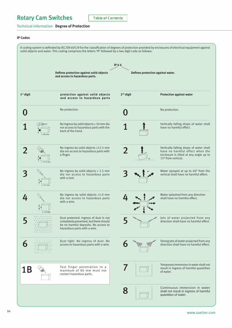
94 www.saelzer.com
Rotary Cam Switches
Technical Information Degree of Protection
A coding system is defi nded by IEC/EN 60529 for the classifi cation of degrees of protection provided by enclosures of electrical equipment against solid objects and water. This coding comprises the letters ‘IP‘ followed by a two digit code as follows:
0
protection against solid objects and access to hazardous parts
No protection.
1No ingress by solid objects ≥ 50 mm dia nor access to hazardous parts with the back of the hand.
2
3
4
5
6
0No protection.
1Veritcally falling drops of water shall have no harmful effect.
2Vertically falling drops of water shall have no harmful effect when the enclosure is tilted at any angle up to 15° from vertical.
3Water sprayed at up to 60° from the vertical shall have no harmful effect.
4Water splashed from any direction shall have no harmful effect.
5Jets of water projected from any direction shall have no harmful effect.
6Strong jets of water projected from any direction shall have no harmful effect.
7Temporary immersion in water shall not result in ingress of harmful quantities of water.
8Continuous immersion in water shall not result in ingress of harmful quantities of water.
Dust protected. Ingress of dust is not completely prevented, but there should be no harmful deposits. No access to hazardous parts with a wire.
Dust tight. No ingress of dust. No access to hazardous parts with a wire.
No ingress by solid objects ≥12.5 mm dia nor access to hazardous parts with a fi nger.
No ingress by solid objects ≥ 2.5 mm dia nor access to hazardous parts with a tool.
No ingress by solid objects ≥1.0 mm dia nor access to hazardous parts with a wire.
1BTest f inger penetrat ion to a maximum of 80 mm must not contact hazardous parts.
Defi nes protection against solid objects and access to hazardous parts.
Defi nes protection against water.
1st digit Protection against water2nd digit
IP 6 6
IP Codes
NS_engl.indb 94NS_engl.indb 94 14.09.2017 08:57:3814.09.2017 08:57:38
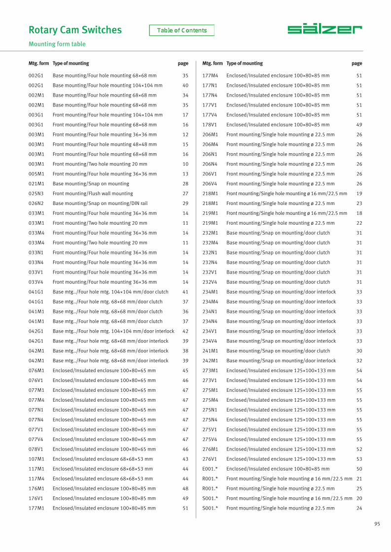
95
Rotary Cam Switches
Mounting form table
002G1 Base mounting/Four hole mounting 68×68 mm 35
002G1 Base mounting/Four hole mounting 104×104 mm 40
002M1 Base mounting/Four hole mounting 68×68 mm 34
002M1 Base mounting/Four hole mounting 68×68 mm 35
003G1 Front mounting/Four hole mounting 104×104 mm 17
003G1 Front mounting/Four hole mounting 68×68 mm 16
003M1 Front mounting/Four hole mounting 36×36 mm 12
003M1 Front mounting/Four hole mounting 48×48 mm 15
003M1 Front mounting/Four hole mounting 68×68 mm 16
003M1 Front mounting/Two hole mounting 20 mm 10
005M1 Front mounting/Four hole mounting 36×36 mm 13
021M1 Base mounting/Snap on mounting 28
025N3 Front mounting/Flush wall mounting 27
026N2 Base mounting/Snap on mounting/DIN rail 29
033M1 Front mounting/Four hole mounting 36×36 mm 14
033M1 Front mounting/Two hole mounting 20 mm 11
033M4 Front mounting/Four hole mounting 36×36 mm 14
033M4 Front mounting/Two hole mounting 20 mm 11
033N1 Front mounting/Four hole mounting 36×36 mm 14
033N4 Front mounting/Four hole mounting 36×36 mm 14
033V1 Front mounting/Four hole mounting 36×36 mm 14
033V4 Front mounting/Four hole mounting 36×36 mm 14
041G1 Base mtg../Four hole mtg. 104×104 mm/door clutch 41
041G1 Base mtg../Four hole mtg. 68×68 mm/door clutch 37
041M1 Base mtg../Four hole mtg. 68×68 mm/door clutch 36
041M1 Base mtg../Four hole mtg. 68×68 mm/door clutch 37
042G1 Base mtg../Four hole mtg. 104×104 mm/door interlock 42
042G1 Base mtg../Four hole mtg. 68×68 mm/door interlock 39
042M1 Base mtg../Four hole mtg. 68×68 mm/door interlock 38
042M1 Base mtg../Four hole mtg. 68×68 mm/door interlock 39
076M1 Enclosed/Insulated enclosure 100×80×65 mm 45
076V1 Enclosed/Insulated enclosure 100×80×65 mm 46
077M1 Enclosed/Insulated enclosure 100×80×65 mm 47
077M4 Enclosed/Insulated enclosure 100×80×65 mm 47
077N1 Enclosed/Insulated enclosure 100×80×65 mm 47
077N4 Enclosed/Insulated enclosure 100×80×65 mm 47
077V1 Enclosed/Insulated enclosure 100×80×65 mm 47
077V4 Enclosed/Insulated enclosure 100×80×65 mm 47
078V1 Enclosed/Insulated enclosure 100×80×65 mm 46
107M1 Enclosed/Insulated enclosure 68×68×53 mm 43
117M1 Enclosed/Insulated enclosure 68×68×53 mm 44
117M4 Enclosed/Insulated enclosure 68×68×53 mm 44
176M1 Enclosed/Insulated enclosure 100×80×85 mm 48
176V1 Enclosed/Insulated enclosure 100×80×85 mm 49
177M1 Enclosed/Insulated enclosure 100×80×85 mm 51
177M4 Enclosed/Insulated enclosure 100×80×85 mm 51
177N1 Enclosed/Insulated enclosure 100×80×85 mm 51
177N4 Enclosed/Insulated enclosure 100×80×85 mm 51
177V1 Enclosed/Insulated enclosure 100×80×85 mm 51
177V4 Enclosed/Insulated enclosure 100×80×85 mm 51
178V1 Enclosed/Insulated enclosure 100×80×85 mm 49
206M1 Front mounting/Single hole mounting ø 22.5 mm 26
206M4 Front mounting/Single hole mounting ø 22.5 mm 26
206N1 Front mounting/Single hole mounting ø 22.5 mm 26
206N4 Front mounting/Single hole mounting ø 22.5 mm 26
206V1 Front mounting/Single hole mounting ø 22.5 mm 26
206V4 Front mounting/Single hole mounting ø 22.5 mm 26
218M1 Front mounting/Single hole mounting ø 16 mm/22.5 mm 19
218M1 Front mounting/Single hole mounting ø 22.5 mm 23
219M1 Front mounting/Single hole mounting ø 16 mm/22.5 mm 18
219M1 Front mounting/Single hole mounting ø 22.5 mm 22
232M1 Base mounting/Snap on mounting/door clutch 31
232M4 Base mounting/Snap on mounting/door clutch 31
232N1 Base mounting/Snap on mounting/door clutch 31
232N4 Base mounting/Snap on mounting/door clutch 31
232V1 Base mounting/Snap on mounting/door clutch 31
232V4 Base mounting/Snap on mounting/door clutch 31
234M1 Base mounting/Snap on mounting/door interlock 33
234M4 Base mounting/Snap on mounting/door interlock 33
234N1 Base mounting/Snap on mounting/door interlock 33
234N4 Base mounting/Snap on mounting/door interlock 33
234V1 Base mounting/Snap on mounting/door interlock 33
234V4 Base mounting/Snap on mounting/door interlock 33
241M1 Base mounting/Snap on mounting/door clutch 30
242M1 Base mounting/Snap on mounting/door interlock 32
273M1 Enclosed/Insulated enclosure 125×100×133 mm 54
273V1 Enclosed/Insulated enclosure 125×100×133 mm 54
275M1 Enclosed/Insulated enclosure 125×100×133 mm 55
275M4 Enclosed/Insulated enclosure 125×100×133 mm 55
275N1 Enclosed/Insulated enclosure 125×100×133 mm 55
275N4 Enclosed/Insulated enclosure 125×100×133 mm 55
275V1 Enclosed/Insulated enclosure 125×100×133 mm 55
275V4 Enclosed/Insulated enclosure 125×100×133 mm 55
276M1 Enclosed/Insulated enclosure 125×100×133 mm 52
276V1 Enclosed/Insulated enclosure 125×100×133 mm 53
E001.* Enclosed/Insulated enclosure 100×80×85 mm 50
R001.* Front mounting/Single hole mounting ø 16 mm/22.5 mm 21
R001.* Front mounting/Single hole mounting ø 22.5 mm 25
S001.* Front mounting/Single hole mounting ø 16 mm/22.5 mm 20
S001.* Front mounting/Single hole mounting ø 22.5 mm 24
Mtg. form Type of mounting page Mtg. form Type of mounting page
NS_engl.indb 95NS_engl.indb 95 14.09.2017 08:57:3814.09.2017 08:57:38

96 www.saelzer.com
Rotary Cam Switches
Technical Information Technical Data
Rated data
* use this version for 600V AC UL/CSA application 1 with terminal extensions for cable lug connection
Rated data P110 M220P220
M221*P221*
P225 M225P226*
T225 S432 S440 S606 S608 S612 S825
Operational voltage Ue
(V AC) 440 690 690 690 690 690 690 690 690 690 690 690
Impulse withstand voltage Uimp
(kV) 4 4 4 6 6 6 6 6 6 6 6 6
Overvoltage category III III III III III III III III III III III III
Pollution degree 3 3 3 3 3 3 3 3 3 3 3 3
Uninterrupted current Iu / I
th / I
the(A) 10 20 20 25 25 32 50 63 80 100 160 315
Load carrying capacity inintermittend operation (class 12)
(AB) DF: 60% = 1.3 × Ie / 40% = 1.6 × I
e / 25% = 2 × I
e
Breaking capacity 220–240V (A) 90 180 180 255 255 370 520 550 600 700 900 1800
380–440V (A) 70 150 150 230 230 300 430 500 550 600 850 1650
500–690V (A) — 90 90 270 270 210 280 380 420 450 340 350
short-circuit rating (max. fuse) (gL) 10 20 20 25 25 32 50 63 80 100 160 315
Conditional short-circuit current (kAeff
) 3 10 10 10 10 15 20 20 25 25 25 25
Isolating characteristics(to EN 60947)
(up to ... V AC) 480 480 480 690 690 690 690 690 690 690 690 690
Switching angle 30° / 45° / 60° / 90°
Contacts (Current paths) (max.) 16 24 24 24 24 24 24 24 24 24 24 24
Current heat loss per contact at Iu
(W) 0.3 0.65 0.65 0.75 0.75 1 3 3.5 4 5 11 28.5
Terminal capacity
solid or strandedmin. (mm²) 0.75 1 1 1.5 1.5 2.5 2.5 4 6 10 10 1851
max. (mm²) 1.5 2.5 2.5 4 4 6 10 16 25 35 70 1851
fl exible or multiwire(including ferrule)
min. (mm²) 0.75 1 1 1.5 1.5 1.5 2.5 2.5 6 10 10 1851
max. (mm²) 1.5 2.5 2.5 2.5 2.5 4 6 10 16 25 50 1851
American Wire Gauge (AWG) 16 12 12 10 10 10 6 4 4 1/0 2/0 350MCM
Thread dimensions for terminal screw M2.5 M3 M3 M3.5 M3.5 M4 M5 M5 2×M4 2×M5 2×M6 M12
Terminal tightening torquemin. (Nm) 0.4 0.5 0.5 0.8 0.8 1.2 2 2 1.2 2 2.5 14
max. (Nm) 0.6 1 1 1.5 1.5 2.5 4 4 2.5 4 6 25
Operational current Ie
AC-21A (A) 10 20 20 25 25 32 50 63 80 100 160 315
AC-22A220–500V (A) 10 20 20 25 25 32 50 63 80 100 160 315
660–690V (A) — 20 20 25 25 32 50 60 80 80 125 125
AC-23A (cos φ = 0.65) 440V (A) 6 16 16 22 22 30 44 50 65 80 120 285
cUL General Use300V AC (A) 10 20 20 25 25 35 551 701 951 1101 1751 240
600V AC (A) — — 20 — 25 35 551 701 951 1101 1751 240
Operational power 50–60 Hz (3 phase)
AC-23A
220–240V (kW) 1.8 4 4 5.5 5.5 7.5 11 15 30 30 37 75
380–440V (kW) 3 7.5 7.5 11 11 15 22 30 45 55 75 132
500V (kW) — 7.5 7.5 11 11 15 30 45 55 55 90 132
660–690V (kW) — 7.5 7.5 11 11 15 30 37 45 45 55 55
AC-3
220–240V (kW) 1.5 3 3 4 4 5.5 11 15 15 22 22 37
380–440V (kW) 2.2 5.5 5.5 7.5 7.5 11 22 30 30 37 45 55
500V (kW) — 5.5 5.5 7.5 7.5 11 22 30 30 37 45 55
660–690V (kW) — 5.5 5.5 7.5 7.5 11 22 30 30 37 45 55
cUL
110–120V AC (HP) 0.5 1 1 1.5 1.5 3 5 7.5 10 10 15 25
208V AC (HP) 0.5 2 2 5 5 7.5 7.5 7.5 10 15 15 30
220–240V AC (HP) 0.5 2 2 5 5 7.5 10 15 15 15 15 30
440–480V AC (HP) — — 5 — 10 10 20 30 30 30 40 50
550–600V AC (HP) — — 5 — 10 10 25 40 50 50 50 50
NS_engl.indb 96NS_engl.indb 96 14.09.2017 08:57:3814.09.2017 08:57:38
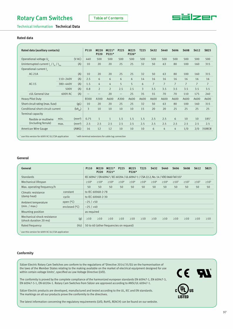
97
General
Sälzer Electric Rotary Cam Switches are conform to the regulations of ‘Directive 2014/35/EU on the harmonisation of the laws of the Member States relating to the making available on the market of electrical equipment designed for use within certain voltage limits‘, specifi ed as Low Voltage Directive (LVD).
The conformity is proved by the complete compliance of the harmonized european standards EN 60947-1, EN 60947-3, EN 60947-5-1, EN 60204-1. Rotary Cam Switches from Sälzer are approved according to ANSI/UL 60947-1.
Sälzer Electric products are developed, manufactured and tested according to the UL, IEC and EN standards. The markings on all our products prove the conformity to the directives.
The latest information concerning the regulatory requirements (LVD, RoHS, REACH) can be found on our website.
Conformity
Rotary Cam Switches
Technical Information Technical Data
Rated data
General P110 M220 M221* P225 M225 T225 S432 S440 S606 S608 S612 S825P220 P221* P226*
Standards IEC 60947 / EN 60947 / IEC 60204 / UL 60947-1 / CSA 22.2, No. 14 / VDE 0660 Teil 107
Mechanical lifespan ≥106 ≥106 ≥106 ≥106 ≥106 ≥106 ≥106 ≥106 ≥105 ≥105 ≥105 ≥105
Max. operating frequency/h 50 50 50 50 50 50 50 50 50 50 50 50
Climatic resistance(damp heat)
constant to IEC 60068-2-78
cyclic to IEC 60068-2-30
Ambient temperature(min. / max.)
open (°C) –25 / +50
enclosed (°C) –25 / +40
Mounting position as required
Mechanical shock resistance(shock duration 20 ms)
(g) ≥10 ≥10 ≥10 ≥10 ≥10 ≥10 ≥10 ≥10 ≥10 ≥10 ≥10 ≥10
Rated frequency (Hz) 50 to 60 (other frequencies on request)
Rated data (auxiliary contacts) P110 M220P220
M221*P221*
P225 M225P226*
T225 S432 S440 S606 S608 S612 S825
Operational voltage Ue
(V AC) 440 500 500 500 500 500 500 500 500 500 500 500
Uninterrupted current Iu / I
th / I
the(A) 10 20 20 25 25 32 50 63 80 100 160 315
Operational current Ie
AC-21A (A) 10 20 20 25 25 32 50 63 80 100 160 315
AC-15
110–240V (A) 2.5 6 6 6 6 14 16 16 16 16 16 16
380–440V (A) 1.5 4 4 5 5 6 7 7 7 7 7 7
500V (A) 0.8 2 2 2.5 2.5 3 3.5 3.5 3.5 3.5 3.5 3.5
cUL General Use 600V AC (A) — — 20 — 25 35 55 70 70 110 175 240
Heavy Pilot Duty B300 A300 A600 A300 A600 A600 A600 A600 A600 A600 A600 A600
Short-circuit rating (max. fuse) (gL) 10 20 20 25 25 32 50 63 80 100 160 315
Conditional short-circuit current (kAeff
) 3 10 10 10 10 15 20 20 25 25 25 25
Terminal capacity
fl exible or multiwire(including ferrule)
min. (mm²) 0.75 1 1 1.5 1.5 1.5 2.5 2.5 6 10 10 1851
max. (mm²) 2.5 2.5 2.5 2.5 2.5 2.5 2.5 2.5 2.5 2.5 2.5 2.5
American Wire Gauge (AWG) 16 12 12 10 10 10 6 4 4 1/0 2/0 350MCM
* use this version for 600V AC UL/CSA application
* use this version for 600V AC UL/CSA application 1 with terminal extensions for cable lug connection
NS_engl.indb 97NS_engl.indb 97 14.09.2017 08:57:3914.09.2017 08:57:39

98 www.saelzer.com
NORWAY
EFA ELEKTRO A. S.Postboks 5931411 Kolbotn
T +47 - 6681 2400
AUSTRIA
Schmachtl GmbHPummererstraße 364020 Linz
T +43 (0) 7 32 - 76 46-0F +43 (0) 7 32 - 78 50 36
offi [email protected]
NETHERLANDS
Solar Nederland B.V.Toermalijnstraat 71812 RL Alkmaar
T +31 (0) 88 - 765 2700
SINGAPORE
Electrimec Asia Pacifi c Pte Ltd17 Tuas Street (Off Pioneer Road)Singapore 638454
T +65 - 6896 2979F +65 - 6896 2925
SPAIN
Euromatel S. L.Avenida Real de Pinto, 87Nave II-A28021 Madrid
T +34 - 91 - 3 58 92 70F +34 - 91 - 3 58 92 95
SWITZERLAND
EHS Elektrotechnik AGIndustriestrasse 268604 Volketswil
T +41 (0) 44 - 908 40 50F +41 (0) 44 - 908 40 55
BELGIUM LUXEMBURG
Bintz technics N. V.Brixtonlaan 23Business Park1930 Zaventem
T +32 (0) 2 - 720 49 16F +32 (0) 2 - 720 37 50
CZECHIA SLOVAKIA
WAPRO spol. s r.o.Rumunská 2779601 Prostějov
T +420 582 334 676F +420 582 334 677
FINLAND UTU OyValimotie 26 B (P. O. Box 252)01531 Vantaa
T +358 - 9 - 2746 411F +358 - 9 - 2746 4141
www.utu.eu
ITALY
Telestar S. r. l.Via Novara, 3528010 Vaprio d'Agogna (NO)
T +39 (0) 0321 966 768F +39 (0) 0321 996 281
KUWAIT
The United TowersTrading & Contracting Est.Old Khaitan, Block 45+46, Building 12KWT 13157 Offi ce No.1, Mezzanine
T +965 - 24745960F +965 - 24727452
SOUTH AFRICA
Waco Industries11, Cleveland RoadCleveland – Johannesburg
T +27 (0) 11 - 677 2500F +27 (0) 11 - 677 2608
GERMANY
Sälzer Electric GmbH
Matthiasstraße 16 57482 Wenden
T +49 (0) 27 62 - 6 14-110F +49 (0) 27 62 - 6 14-100
[email protected] www.saelzer.com
GREAT BRITAIN
Salzer UK Ltd.
44 Edison Road Aylesbury Bucks. HP19 8TE
T +44 (0) 12 96 - 39 99 92F +44 (0) 12 96 - 39 22 29
[email protected] www.salzeruk.co.uk
U. S.A. / CANADA / MEXICO
Salzer USA Corporation
3802 N. 54th Street Mesa, AZ 85215
T +1 480-325-2690F +1 480-985-9663
Rotary Cam Switches
Contacts
Your contacts worldwide
DENMARK
Regal A/SIndustrivej 44000 Roskilde
T +45 - 46 77 70 00F +45 - 46 75 76 20
NS_engl.indb 98NS_engl.indb 98 14.09.2017 08:57:3914.09.2017 08:57:39

www.saelzer.com
NS
117/
EN
-111
7 ©
by
Säl
zer E
lect
ric G
mbH
· ch
ange
s re
serv
ed
Sälzer Electric GmbHMatthiasstraße 1657482 Wenden (Germany)www.saelzer.com
Headquarters:Tel. +49 (0) 27 62 / 6 14-110Fax +49 (0) 27 62 / 6 [email protected]