low water stream crossings - institute for transportation · · 2002-03-25in this regard, low...
TRANSCRIPT

LOW WATER STREAM CROSSINGS:DESIGN AND CONSTRUCTION RECOMMENDATIONS
DECEMBER 2001
Sponsored bythe Iowa Department of Transportationand the Iowa Highway Research Board
CTRE Project 01-78Iowa DOT Project TR-453
Center for Transportation
Research and Education
CTRE
FINAL REPORT
Department of Civil and Construction Engineering

CTRE’s mission is to develop and implement innovative methods, materials, and technologiesfor improving transportation efficiency, safety, and reliability while improving the learningenvironment of students, faculty, and staff in transportation-related fields.
The opinions, findings, and conclusions expressed in this publication are those of theauthors and not necessarily those of the Iowa Department of Transportation.
ABSTRACT
Most counties have bridges that are no longer adequate, and are faced with large capitalexpenditure for replacement structures of the same size. In this regard, low water streamcrossings (LWSCs) can provide an acceptable, low cost alternative to bridges and culverts onlow volume and reduced maintenance level roads. In addition to providing a low cost optionfor stream crossings, LWSCs have been designed to have the additional benefit of streambedstabilization.
Considerable information on the current status of LWSCs in Iowa, along with insight ofneeds for design assistance, was gained from a survey of county engineers that was con-ducted as part of this research (Appendix A). Copies of responses and analysis are includedin Appendix B.
This document provides guidelines for the design of LWSCs. There are three common typesof LWSCs: unvented ford, vented ford with pipes, and low water bridges. Selection amongthese depends on stream geometry, discharge, importance of road, and budget availability. Tominimize exposure to tort liability, local agencies using low water stream crossings shouldconsider adopting reasonable selection and design criteria and certainly provide adequatewarning of these structures to road users. The design recommendations included in thisreport for LWSCs provide guidelines and suggestions for local agency reference. Severaldesign examples of design calculations are included in Appendix E.
LOW WATER STREAM CROSSINGS:DESIGN AND CONSTRUCTION RECOMMENDATIONS
FINAL REPORT
Principal InvestigatorR. A. Lohnes
Professor of Civil and Construction Engineering, Iowa State University
Co-Principal InvestigatorsR. R. Gu
Associate Professor of Civil and Construction Engineering, Iowa State University
T. McDonaldSafety Circuit Rider, Center for Transportation Research and Education, Iowa State University
Research AssistantM. K. Jha
Department of Civil and Construction Engineering, Iowa State University
Preparation of this report was financed in partthrough funds provided by the Iowa Department of Transportation
through its research management agreement with theCenter for Transportation Research and Education.
CTRE Project 01-78Iowa DOT Project TR-453
Center for Transportation Research and EducationIowa State University
ISU Research Park2901 South Loop Drive, Suite 3100
Ames, Iowa 50010-8632Telephone: 515-294-8103
Fax: 515-294-0467www.ctre.iastate.edu/
DECEMBER 2001

TABLE OF CONTENTS
1 INTRODUCTION...................................................................................................................1
2 SELECTION OF LWSC SITE AND STRUCTURE ...............................................................42.1 Data collection ..................................................................................................................42.2 Site selection criteria .........................................................................................................72.3 LWSC selection................................................................................................................7
2.3.1 Unvented ford.............................................................................................................82.3.2 Vented ford.................................................................................................................82.3.3 Low water bridge........................................................................................................8
3 LWSC DESIGN......................................................................................................................93.1 Design considerations........................................................................................................93.2 Design of fords ............................................................................................................ ....10
3.2.1 Unvented ford...........................................................................................................103.2.2 Vented ford............................................................................................................. .133.2.3 Low water bridge.....................................................................................................14
4 LWSC CONSTRUCTION ....................................................................................................194.1 Unvented ford.............................................................................................................. ....194.2 Vented ford .....................................................................................................................20
4.2.1 Streambed preparation .............................................................................................204.2.2 Installation of pipes..................................................................................................204.2.3 Riding surface considerations ..................................................................................214.2.4 Erosion protection of structure side and core material ..............................................214.2.5 Erosion protection of streambed...............................................................................22
4.3 Low water bridge........................................................................................................... ..23
5 TRAFFIC CONTROLS.........................................................................................................245.1 Recommended signing....................................................................................................24
5.1.1 Flood Area Ahead sign ............................................................................................245.1.2 Impassable During High Water sign.........................................................................245.1.3 Do Not Enter When Flooded sign ............................................................................25
5.2 Other suggestions ...........................................................................................................25
6 LEGAL CONSIDERATIONS...............................................................................................27
7 REFERENCES .................................................................................................................. ...28
8 ACKNOWLEDGEMENTS...................................................................................................29
APPENDIX A: 2001 SURVEY ON THE USE OF LOW WATER STREAM CROSSINGS.....30
APPENDIX B: SUMMARY OF SURVEY RESPONSES ........................................................32LWSCs in service (Question 1) .............................................................................................33Experience with LWSCs design and construction (Question 2)..............................................34

Preferences on LWSC types (Question 3)..............................................................................35Legal experience with LWSCs (Question 4) ..........................................................................35Suggestions on the use of LWSCs (Question 5).....................................................................35Benefit from a LWSCs manual (Question 6) .........................................................................36Suggestion of topics for manual (Question 7) ........................................................................37Support for LWSCs applications in Iowa counties if manual were available (Question 8)......38
APPENDIX C: MANNINGÕS ROUGHNESS COEFFICIENT (N) FOR NATURAL STREAMCHANNELS.............................................................................................................................39
APPENDIX D: DESIGN OF A VENTED FORDÑSIZE AND NUMBER OF PIPES..............40D.1 Design Curves (D vs. Qvent)...........................................................................................40D.2 HEC-5 charts .................................................................................................................41D.3 Computer programÑCulvertMaster...............................................................................42
APPENDIX E: DESIGN EXAMPLES......................................................................................44E.1 Example One ..................................................................................................................44E.2 Example Two..................................................................................................................45E.3 Example Three...............................................................................................................45E.4 Example Four..................................................................................................................47E.5 Example Five ..................................................................................................................48E.6 Example Six....................................................................................................................49

1
1 INTRODUCTION
There is an increasing need for replacement of many old, unsafe bridges on low volume roads.Most counties have bridges that are no longer adequate, and are faced with large capitalexpenditure for replacement structures of the same size. In this regard, low water streamcrossings (LWSCs) can provide an acceptable, low cost alternative to bridges and culverts onlow volume and reduced maintenance level roads.
A LWSC is a structure that provides reasonable access as a stream crossing but will beflooded periodically and therefore closed to traffic. These structures are relatively inexpensiveand particularly suitable for low volume roads, across streams with periodically dry beds, orstreams where the normal depth of flow is relatively low. In addition to providing a low costoption for stream crossings, LWSC have been designed to have the additional benefit ofstreambed stabilization.
This document provides guidelines for the design of LWSCs and is a synthesis and summaryof previous studies reports from Iowa State University, Federal Highway Administration reportsand common practices of Iowa county engineers. Results of the research on LWSCs including asurvey of the county engineers, suggestions from an advisory group, field trip observations andthe ideas of individual engineers provided valuable input for the design recommendations andare included in Appendix A and Appendix B. In an attempt to make this report Òuser friendlyÓmost theoretical analyses and experimental results are omitted, but can be found in referencescited in this document.
There are three common types of LWSCs: unvented ford, vented ford with pipes, and lowwater bridges. Selection among these depends on stream geometry, discharge, importance ofroad, and budget availability. Experience suggests that a normal low water bridge may cost about$40,000 to $50,000, whereas a vented ford may be constructed for $15,000 to $20,000. A briefdescription of different types of LWSC is given as follows:
1) An unvented ford (no pipes) is a structure that crosses streams that are dry most of the yearor where normal streamflow is less than 6 inches in depth (Figure 1). Unvented fords canbe placed to conform with the streambed or the crossing elevation can be raised up to 4 ftabove the streambed. The grades of the roadway approaches are shaped to provide asmooth transition with acceptable slopes of less than 10%. The crossing may beconstructed of crushed stone, riprap, precast concrete slabs, or other suitable material.
Figure 1. Unvented ford.

2
2) A vented ford is a LWSC that has pipe(s) under the crossing that accommodate low flowswithout overtopping the road (Figure 2). High water will periodically flow over thecrossing. Approaches are designed to provide acceptable grades of less than 10% byshaping the roadway or adjusting the elevation of the crossing. The pipe(s) or culverts maybe embedded in earth fill, aggregate, riprap, or portland cement concrete.
3) A low water bridge is a flat-slab bridge deck (Figure 3) constructed at about the elevationof the adjacent stream banks, with the smooth cross section designed to allow high water toflow over the bridge surface without damaging the structure.
This report summarizes a simplified approach for LWSC selection and design. Figure 4 is aflowchart showing a process for LWSC design and construction.
Figure 2 Vented ford in Tama County, Iowa.
Figure 3 Low water bridge in Benton County, Iowa.

3
Figure 4 Flow chart for LWSC design and construction.
Data collection
LWSC construction
Site selection for LWSC
LWSC selection
LWSC design
Geometry Crossing materials
Unvented ford
Water depthover LWSC
Discharge and velocity
Design flow
Budget
Stream type
Vented ford Low water bridge

4
2 SELECTION OF LWSC SITE AND STRUCTURE
2.1 Data collection
When a LWSC structure is considered, other options, such as replacing the existing structure andclosing the road, should also be reviewed for the site and feasibility assessed. Following is a listof data that may be used in determining potential sites as well as geometric design and materialselection for low water stream crossings:
1) Type of stream:Perennial: water flows in the stream at least 90% of the time in a well-defined channel.Intermittent: flow generally occurs only during the wet season (50% of the time or less).Ephemeral: flow generally occurs for a short time after extreme storms. The channel isusually not well defined.
2) Type of road: paved, gravel, or dirt (Area Service Level A, B, or C).3) Use of road: dwellings, recreation, farm access, school, mail route, alternate available access,
etc.4) Channel geometry: width, depth, side slope, and longitudinal slope.5) ManningÕs roughness coefficient (n) (see Appendix C).6) Roadway geometry: width, approach grades, and height of roadway above streambed.7) Drainage area: drainage area can be determined by measuring watershed area on USGS
topographic maps or by consulting Bulletin No. 7 (Larimer, 1957).8) Historical daily discharges at the site for the development of a flow-duration curve.9) Level of access desired or tolerable time out of service.10) Design flow for the acceptable closing duration per year is determined from the flow-
duration curve at a gaged site or flow-duration-area equations at ungaged sites.
A flow-duration curve indicates the percent of time, within a certain period, in which givenrates of flow were equaled or exceeded. The curve is prepared by arranging the daily dischargescollected in the past. Flow-duration information for daily flows collected at all the gagingstations in Iowa can be found in Lara (1979). The road and LWSC is closed when a designdischarge, Qe, is equaled or exceeded and results in LWSC overtopping. The acceptable closingpercent of time per year (e) can be called as the design exceedence probability. For example, a2% exceedence probability means the crossing will be closed, on the average, for 2% time of ayear, i.e. 7 days in the year, because the design discharge, Q2%, is equaled or exceeded and thecrossing structure is overtopped during that time period.
Flow-duration information at ungaged sites in Iowa can be found in Rossmiller et al. (1984).Flow-duration-area equations for ungaged streams were developed from flow data at gaged sitesby dividing Iowa into three different hydrological regions (Figure 5). The equations arepresented and plotted as the flow-duration-area curves in this report (Figures 6, 7, and 8). Thehydrologic region of the site is identified from Figure 5. The design discharge, Qe, at anungaged site with a drainage area of A for a selected exceedence probability, e, is determinedfrom corresponding flow-duration-area curves (Figures 6-8).

5
Figure 5 Hydrologic regions of Iowa for discharge estimation.
0
500
1000
1500
2000
2500
3000
0 50 100 150 200 250 300 350 400 450 500
Drainage area (A), mi2
Des
ign
dis
char
ge
(Qe ),
cfs
Figure 6 Discharge estimation for Region I.
be aAQ =
e a b
502510521
0.170.521.372.586.7813.50
1.051.010.980.960.9
0.85
10%
5%
2%
1%Exceedence probability, e
Region I
Lyon Osceola Dickinson
Cherokee
KossuthSioux Obrien Clay Palo Alto
HumboldtPlymouth
Emmet
Pocahontas Wright
Worth
Hancock CerroGordo
Franklin
Woodbury Idagrove Sac Calhoun Webster
Hamilton Hardin
Monona
Mitchell HowardWinneshiek Allamakee
Floyd Chickasaw
Fayette Clayton
ButlerBremer
GrundyBlackHawk
Buchanan Delaware Dubuque
Jackson
Clinton
JonesLinn
Cedar
Scott
Muscatine
Johnson
Benton
Iowa
Tama
Poweshiek
CrawfordMarshallStory
JasperPolk
BooneGreeneCarroll
DallasGuthrieAudubonShelbyHarrison
Pottawattamie Cass Adair Madison
Clarke
MarionWarren
Lucas Wapello
AppanooseWayneDecatur
UnionAdamsMontgo
meryMills
Fremont Page Taylor Ringgold
Mahaska Keokuk WashingtonLouisa
JeffersonHenryMonroe
DesMoines
Davis VanBuren
Lee
BuenaVista
Winnebago
I
II
III

6
0
500
1000
1500
2000
2500
3000
0 50 100 150 200 250 300 350 400 450 500
Drainage area (A), mi2
Des
ign
dis
char
ge
(Qe ),
cfs
Figure 7 Discharge estimation for Region II.
be aAQ =
e a b
502510521
0.060.240.912.266.7813.50
1.091.061.000.950.900.85
10%
5%
2%
1%Exceedence probability, e
Region II
0
500
1000
1500
0 50 100 150 200 250 300 350 400 450 500
Drainage area (A), mi2
Des
ign
dis
char
ge
(Qe ),
cfs
Figure 8 Discharge estimation for Region III.
10%
5%
2%
1%Exceedence probability, e
be aAQ =
e a b
502510521
0.0150.040.150.331.233.56
1.241.251.191.151.060.96
Region III

7
2.2 Site selection criteria
The following criteria should be considered when selecting a site for a LWSC:
1) A LWSC is recommended only on Area Service B and C level roads: unpaved or primitiveroads, field access roads, roads with no inhabited dwellings, low traffic volume roads, androads with alternate routes available during flooding.
2) Stream channel should be stable. If evidence of aggradation, degradation, or lateral migrationis present at the proposed location the site may not be desirable. However, these issuesshould be considered in the LWSC design.
3) Approach grades to the LWSC structure should be less than 10%.4) Height between road approach and LWSC surface should be less than 12 ft.5) Cost comparison analysis with bridges or culverts should indicate considerable savings.6) A LWSC should not be constructed along roads where a future increase in traffic is expected
due to economic, social and other changes.
Specific guidelines are suggested in Table 1, which are based on an opinion survey in 40 states(Motayed et al., 1982).
Table 1 Site selection factors for LWSC (Motayed et al., 1982).
Criteria Most favorable for LWSC Least favorable for LWSCAverage daily traffic (ADT) Less than 5 vehicles 200 vehicles
Average annual flooding Less than 2 times per year 10 times per year
Average duration of trafficinterruption per occurrence
Less than 24 hours 3 days
Extra travel time for alternateroute
Less than 1 hour 2 hours
Possibility of danger tohuman life
Less than 1 in 1 billion withextra warning systems
1 in 100,000
Property damage None One million dollars
Frequency of using LWSC asan emergency route
None Once per month
2.3 LWSC selection
Generally, for selecting LWSC type (unvented, vented, or low water bridge), the cross-sectional and longitudinal geometry of the stream, magnitude of discharge/flow velocity,importance (classification) of road, traffic volume and alternate access should be considered.For example, if the road is relatively important, a low water bridge might be appropriateregardless the size of the stream. Other factors, such as traffic volume and alternate access mayalso be considered. Following are some guidelines.

8
2.3.1 Unvented ford
Unvented fords are best suited for intermittent or ephemeral streams, or over the wideshallow perennial streams where the velocity is low. For a perennial stream, it is necessary todetermine the depth of flow associated with design discharge, Qe. The probable water depth canbe determined either by site observation over a long period (at least a year or preferably 5 years),or by conducting hydrological and hydraulic analysis as described in Section 3.2.1.1.
The maximum allowable depth of flow over LWSCs is 6 inches (Looschen and Coy, 1982;Motayed et al., 1983). An unvented ford is acceptable only if the probable water depth over theford is less than or equal to 6 inches during the desirable period of year. If the calculated depth offlow over the ford exceeds 6 inches, then a ford constructed above the channel bottom or avented ford should be considered. A raised ford reduces the overtop flow depth if the upstreamflow is sub-critical as is the case in most natural streams. However, when the natural flow issupercritical, a raised ford will cause an increase in flow depth over it. The design is described inSection 3.2.1.2.
2.3.2 Vented ford
Vented fords should be considered where the depth of flow is calculated to exceed6 inches for the desirable period over a raised unvented ford. The flow over the top of the LWSCcan be decreased to a depth less than 6 inches by adding pipe(s) to accommodate low flows. Thedesign of the pipes or vents is described in Section 3.2.2. Figure 9(a) shows the crossing profileof a vented ford, where HW is the depth of headwater, P is the height of the ford above thechannel bottom, H is the upstream head, h is water depth over the ford (ft), and D is the diameterof pipe or the height of vent.
2.3.3 Low water bridge
Low water bridges are an acceptable alternative where higher streamflows, Qe, exceed thecapacity of a vented ford. Low water bridges also may be considered if the watershed has a highpotential for debris that might clog the pipes in a vented ford. If the channel cross section isenvironmentally sensitive to an obstruction, a low water bridge is a possible option. Finally, alow water bridge should be considered if the average daily traffic (ADT) exceeds 5 vehicles perday (Motayed et al., 1983). Two possible structural designs are described in Section 3.2.3.
HWH
P
h
Pipe(s)D
Figure 9(a) Crossing profile of a vented ford.
9
3 LWSC DESIGN
3.1 Design considerations
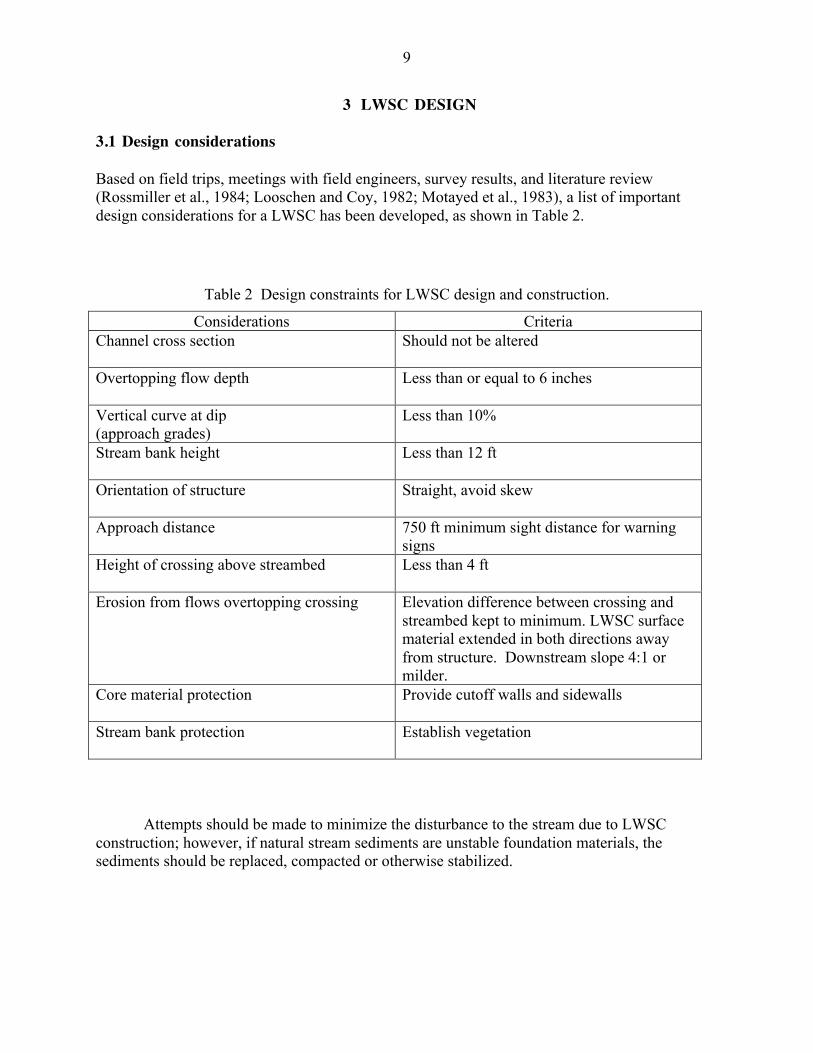
Based on field trips, meetings with field engineers, survey results, and literature review(Rossmiller et al., 1984; Looschen and Coy, 1982; Motayed et al., 1983), a list of importantdesign considerations for a LWSC has been developed, as shown in Table 2.
Table 2 Design constraints for LWSC design and construction.
Considerations CriteriaChannel cross section Should not be altered
Overtopping flow depth Less than or equal to 6 inches
Vertical curve at dip(approach grades)
Less than 10%
Stream bank height Less than 12 ft
Orientation of structure Straight, avoid skew
Approach distance 750 ft minimum sight distance for warningsigns
Height of crossing above streambed Less than 4 ft
Erosion from flows overtopping crossing Elevation difference between crossing andstreambed kept to minimum. LWSC surfacematerial extended in both directions awayfrom structure. Downstream slope 4:1 ormilder.
Core material protection Provide cutoff walls and sidewalls
Stream bank protection Establish vegetation
Attempts should be made to minimize the disturbance to the stream due to LWSCconstruction; however, if natural stream sediments are unstable foundation materials, thesediments should be replaced, compacted or otherwise stabilized.

10
3.2 Design of fords
3.2.1 Unvented ford
Unvented fords are constructed of various materials including riprap or crushed rock, gabions,portland cement concrete, and precast concrete panels. Section 3.2.1.3 provides guidelines forcrushed rock and riprap selection.
Table 3 Design considerations for unvented ford.
Considerations CriteriaPrecast concrete panels
Erosion protection
Markers
Should include a proper filter to prevent piping andconsequent undermining of the crossing.
End walls and/or gabion protection may be desirable; wide,sloped shoulders downstream may be helpful
Provide markers to help drivers spot the limits of the roadwaywhen flooded
3.2.1.1 Ford on channel bottomIf the unvented ford is to be placed on stream bottom with minimum disturbance to
channel cross section, ManningÕs equation combined with the continuity equation can be used inthis form, assuming a rectangular cross section:
( )( )
2
1
3/2
3/5
2
486.1S
Hw
wHn
Qe+
= (1)
where Qe is the design discharge from hydrologic analysis (Section 2.1) in cfs, n is the roughnessfrom Appendix C, S is the channel slope in ft/ft, w is the channel width and H is the depth offlow associated with Qe. Both width and depth are in feet. Given Qe, w, and S, the depth offlow, H, can be determined from Equation (1) by trial and error. For very wide channels, i.e.when
w/H ³ 10 (2)
Equation (1) can be simplified to
5/3
2/1486.1÷ø
öçè
æ=
wS
nQH e (3)
The computed H value can then be compared with the allowable maximum flow depth of 6inches to determine if an unvented ford would be an acceptable option.
11
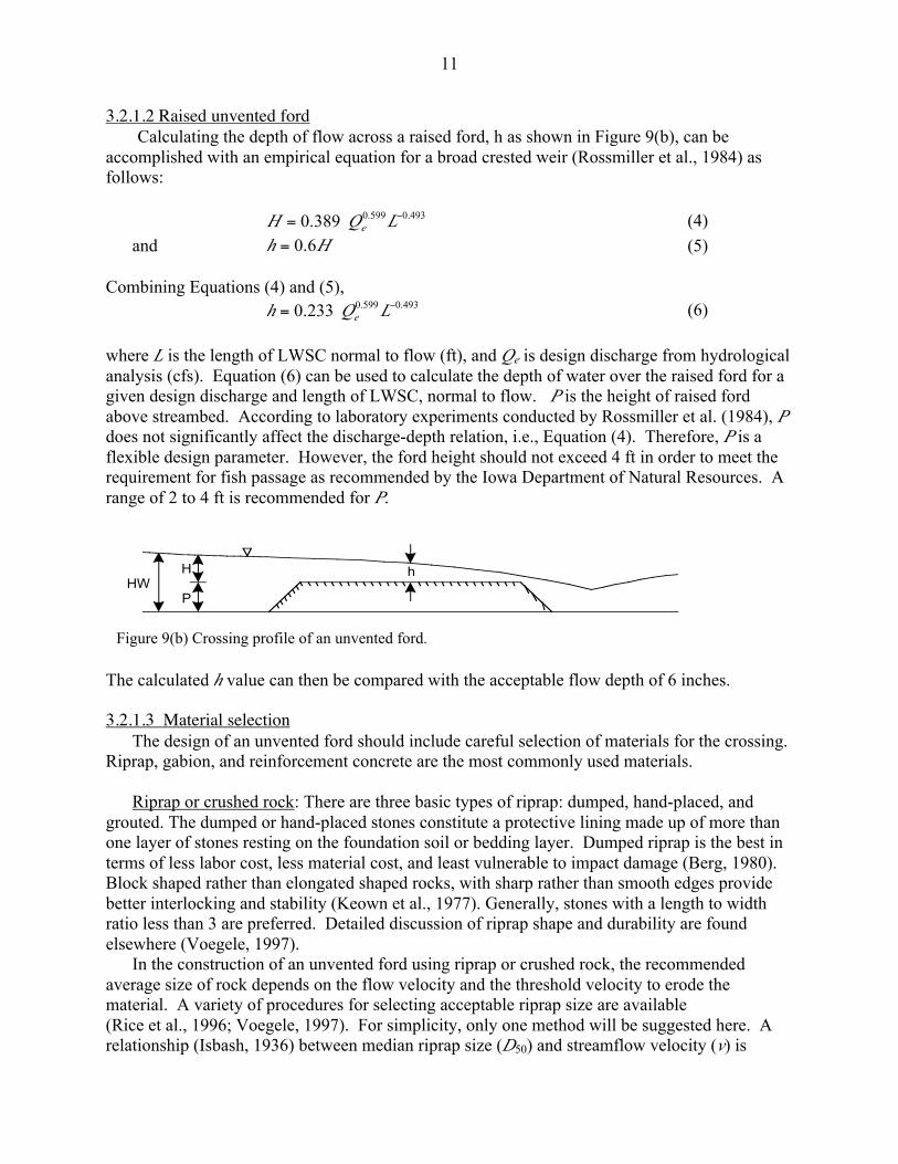
3.2.1.2 Raised unvented fordCalculating the depth of flow across a raised ford, h as shown in Figure 9(b), can be
accomplished with an empirical equation for a broad crested weir (Rossmiller et al., 1984) asfollows:
493.0599.0389.0 -= LQH e (4)
and Hh 6.0= (5)
Combining Equations (4) and (5),493.0599.0233.0 -= LQh e (6)
where L is the length of LWSC normal to flow (ft), and Qe is design discharge from hydrologicalanalysis (cfs). Equation (6) can be used to calculate the depth of water over the raised ford for agiven design discharge and length of LWSC, normal to flow. P is the height of raised fordabove streambed. According to laboratory experiments conducted by Rossmiller et al. (1984), Pdoes not significantly affect the discharge-depth relation, i.e., Equation (4). Therefore, P is aflexible design parameter. However, the ford height should not exceed 4 ft in order to meet therequirement for fish passage as recommended by the Iowa Department of Natural Resources. Arange of 2 to 4 ft is recommended for P.
The calculated h value can then be compared with the acceptable flow depth of 6 inches.
3.2.1.3 Material selectionThe design of an unvented ford should include careful selection of materials for the crossing.
Riprap, gabion, and reinforcement concrete are the most commonly used materials.
Riprap or crushed rock: There are three basic types of riprap: dumped, hand-placed, andgrouted. The dumped or hand-placed stones constitute a protective lining made up of more thanone layer of stones resting on the foundation soil or bedding layer. Dumped riprap is the best interms of less labor cost, less material cost, and least vulnerable to impact damage (Berg, 1980).Block shaped rather than elongated shaped rocks, with sharp rather than smooth edges providebetter interlocking and stability (Keown et al., 1977). Generally, stones with a length to widthratio less than 3 are preferred. Detailed discussion of riprap shape and durability are foundelsewhere (Voegele, 1997).
In the construction of an unvented ford using riprap or crushed rock, the recommendedaverage size of rock depends on the flow velocity and the threshold velocity to erode thematerial. A variety of procedures for selecting acceptable riprap size are available(Rice et al., 1996; Voegele, 1997). For simplicity, only one method will be suggested here. Arelationship (Isbash, 1936) between median riprap size (D50) and streamflow velocity (v) is
HWH
P
h
Figure 9(b) Crossing profile of an unvented ford.

12
presented in Figure 10. A factor of safety of 2 provides a conservative lower rock size. Theminimum value of D50 is arbitrarily limited to 3 inches.
Mean velocity of streamflow can be calculated from ManningÕs equation:213246.1
SRn
v = (7)
where v is velocity of streamflow (ft/s);n is ManningÕs roughness coefficient (see Appendix C);R is hydraulic radius (ft), R = a/p where a is cross-sectional area of flow (ft2) and
p is wetted perimeter of channel (ft). For very wide channels, R = flow depthof river; and
S is slope of streambed (ft/ft), which can be calculated from topographic map or field survey.
Figure 10 Crushed stone size for unvented ford.
Use Equation (7) to calculate velocity for bank-full depth with the ford placed on thestreambed. For a raised ford the cross-sectional area, a, is based on the length of the ford(channel width) and the difference between the bank height and the roadway elevation. Then,with velocity from Equation (7) and Figure 10, determine the median rock size.
Gabions: Gabions are steel wire fabric baskets filled with stones, providing a mass so heavythat water cannot displace them. The advantages of gabions are: they are flexible, thus makingthem less prone to failure from settlement or undermining; they fill up with silt quickly and allowthe establishment of natural vegetation giving a more aesthetically pleasing look; and are 20% to30% cheaper than concrete. However, they are labor intensive and a suitable filter material isrequired to prevent scouring of the underlying soil. Suitable rocks of size 4 to 8 inches aregenerally acceptable.
0
2
4
6
8
10
12
14
0 0.5 1 1.5 2
Median rock size (D50), ft
Mea
n v
elo
city
of
stre
am, f
t/s
Isbash equation With Factor Of Safety = 2
13
Portland Cement Concrete: Cast-in-place or precast concrete is the most expensive materialfor a LWSC. Cast-in-place crossings are difficult to construct in flowing streams and precastpanels may offer construction advantages. Concrete may be the most durable material andrequires the least maintenance; however, adequate protection for scour around the structure mustbe provided. Additionally, sufficient thickness and/or reinforcing should be provided to preventdifferential settlement.
In the construction of an unvented ford, precast panels can be placed directly on thestreambed. The following design details are recommended based on local agency experience:
- Thickness = 8 inches- Length and width: 6 ft ´ 16 ft (vary according to the stream size)- Reinforcement: number 5 bars at 12 inch centers- Panels tied together with 5/8 inch steel cable- Side gaps: filled with 3 to 5 inch crushed stones
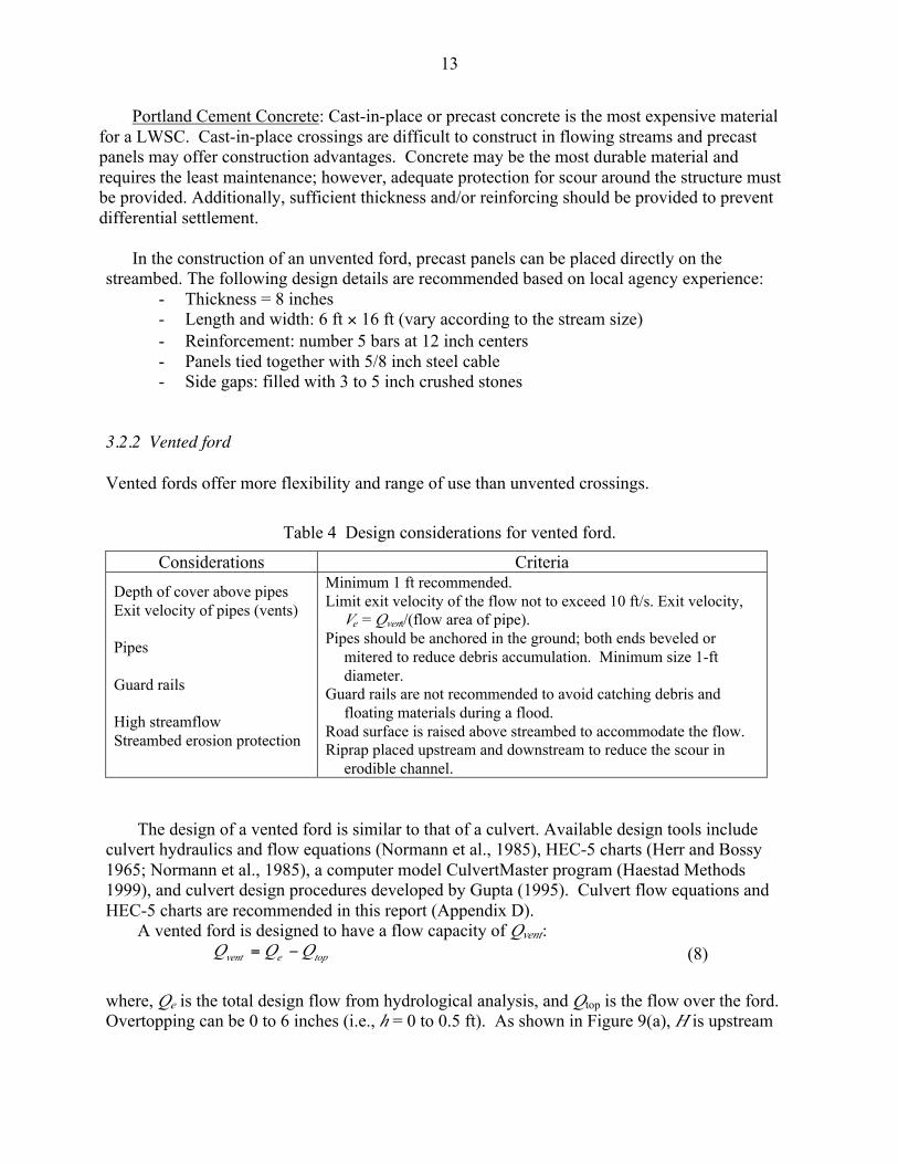
3.2.2 Vented ford
Vented fords offer more flexibility and range of use than unvented crossings.
Table 4 Design considerations for vented ford.
Considerations Criteria
Depth of cover above pipesExit velocity of pipes (vents)
Pipes
Guard rails
High streamflowStreambed erosion protection
Minimum 1 ft recommended.Limit exit velocity of the flow not to exceed 10 ft/s. Exit velocity,
Ve = Qvent/(flow area of pipe).Pipes should be anchored in the ground; both ends beveled or
mitered to reduce debris accumulation. Minimum size 1-ftdiameter.
Guard rails are not recommended to avoid catching debris andfloating materials during a flood.
Road surface is raised above streambed to accommodate the flow.Riprap placed upstream and downstream to reduce the scour in
erodible channel.
The design of a vented ford is similar to that of a culvert. Available design tools includeculvert hydraulics and flow equations (Normann et al., 1985), HEC-5 charts (Herr and Bossy1965; Normann et al., 1985), a computer model CulvertMaster program (Haestad Methods1999), and culvert design procedures developed by Gupta (1995). Culvert flow equations andHEC-5 charts are recommended in this report (Appendix D).
A vented ford is designed to have a flow capacity of Qvent:topevent QQQ -= (8)
where, Qe is the total design flow from hydrological analysis, and Qtop is the flow over the ford.Overtopping can be 0 to 6 inches (i.e., h = 0 to 0.5 ft). As shown in Figure 9(a), H is upstream
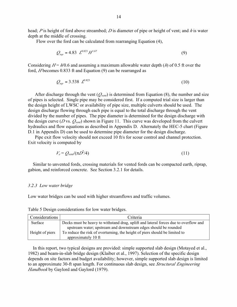
14
head; P is height of ford above streambed; D is diameter of pipe or height of vent; and h is waterdepth at the middle of crossing.
Flow over the ford can be calculated from rearranging Equation (4),
67.1823.083.4 HLQtop = (9)
Considering H = h/0.6 and assuming a maximum allowable water depth (h) of 0.5 ft over theford, H becomes 0.833 ft and Equation (9) can be rearranged as
823.0538.3 LQtop = (10)
After discharge through the vent (Qvent) is determined from Equation (8), the number and sizeof pipes is selected. Single pipe may be considered first. If a computed trial size is larger thanthe design height of LWSC or availability of pipe size, multiple culverts should be used. Thedesign discharge flowing through each pipe is equal to the total discharge through the ventdivided by the number of pipes. The pipe diameter is determined for the design discharge withthe design curve (D vs. Qvent) shown in Figure 11. This curve was developed from the culverthydraulics and flow equations as described in Appendix D. Alternately the HEC-5 chart (FigureD.1 in Appendix D) can be used to determine pipe diameter for the design discharge.
Pipe exit flow velocity should not exceed 10 ft/s for scour control and channel protection.Exit velocity is computed by
Ve = Qvent/(pD2/4) (11)
Similar to unvented fords, crossing materials for vented fords can be compacted earth, riprap,gabion, and reinforced concrete. See Section 3.2.1 for details.
3.2.3 Low water bridge
Low water bridges can be used with higher streamflows and traffic volumes.
Table 5 Design considerations for low water bridges.
Considerations Criteria Surface
Height of piers
Decks must be heavy to withstand drag, uplift and lateral forces due to overflow andupstream water; upstream and downstream edges should be rounded
To reduce the risk of overturning, the height of piers should be limited to approximately 10 ft
In this report, two typical designs are provided: simple supported slab design (Motayed et al.,1982) and beam-in-slab bridge design (Klaiber et al., 1997). Selection of the specific designdepends on site factors and budget availability; however, simple supported slab design is limitedto an approximate 30-ft span length. For continuous slab design, see Structural EngineeringHandbook by Gaylord and Gaylord (1979).

15
0123456789
10111213141516
0 200 400 600 800 1000 1200 1400 1600 1800 2000
Design Flow, Q vent (cfs)
Pip
e S
ize,
D (
ft)
0
1
2
3
4
5
6
0 50 100 150 200 250
Design Flow, Qvent (cfs)
Pip
e S
ize,
D (
ft)
Figure 11 Typical design curves for vented fords using CMP with mitered entrance and underinlet control (barrel slope £ 0.02, use Equation D.1 for different types).
16
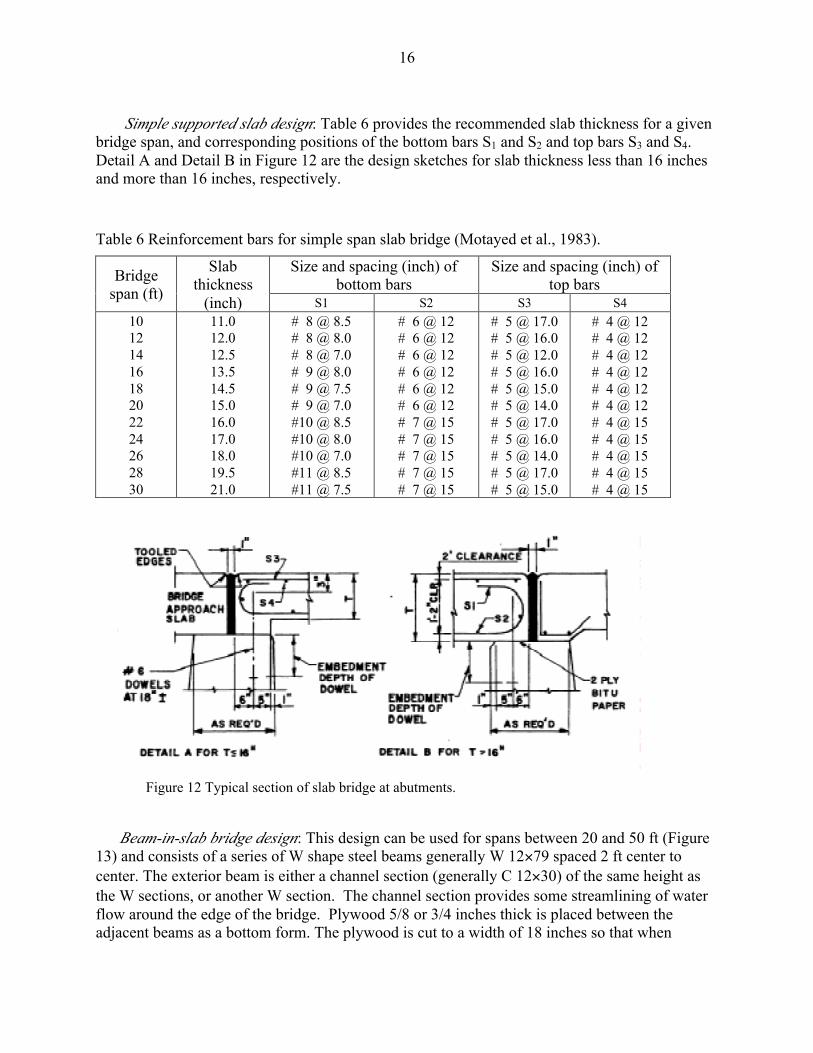
Simple supported slab design: Table 6 provides the recommended slab thickness for a givenbridge span, and corresponding positions of the bottom bars S1 and S2 and top bars S3 and S4.Detail A and Detail B in Figure 12 are the design sketches for slab thickness less than 16 inchesand more than 16 inches, respectively.
Table 6 Reinforcement bars for simple span slab bridge (Motayed et al., 1983).
Size and spacing (inch) ofbottom bars
Size and spacing (inch) oftop barsBridge
span (ft)
Slabthickness
(inch) S1 S2 S3 S4
1012141618202224262830
11.012.012.513.514.515.016.017.018.019.521.0
# 8 @ 8.5# 8 @ 8.0# 8 @ 7.0# 9 @ 8.0# 9 @ 7.5# 9 @ 7.0#10 @ 8.5#10 @ 8.0#10 @ 7.0#11 @ 8.5#11 @ 7.5
# 6 @ 12# 6 @ 12# 6 @ 12# 6 @ 12# 6 @ 12# 6 @ 12# 7 @ 15# 7 @ 15# 7 @ 15# 7 @ 15# 7 @ 15
# 5 @ 17.0# 5 @ 16.0# 5 @ 12.0# 5 @ 16.0# 5 @ 15.0# 5 @ 14.0# 5 @ 17.0# 5 @ 16.0# 5 @ 14.0# 5 @ 17.0# 5 @ 15.0
# 4 @ 12# 4 @ 12# 4 @ 12# 4 @ 12# 4 @ 12# 4 @ 12# 4 @ 15# 4 @ 15# 4 @ 15# 4 @ 15# 4 @ 15
Beam-in-slab bridge design: This design can be used for spans between 20 and 50 ft (Figure13) and consists of a series of W shape steel beams generally W 12´79 spaced 2 ft center tocenter. The exterior beam is either a channel section (generally C 12´30) of the same height asthe W sections, or another W section. The channel section provides some streamlining of waterflow around the edge of the bridge. Plywood 5/8 or 3/4 inches thick is placed between theadjacent beams as a bottom form. The plywood is cut to a width of 18 inches so that when
Figure 12 Typical section of slab bridge at abutments.

17
concrete is placed, it is in contact with the surface of the bottom flange. After the formwork hasdeteriorated, bearing will still exist between the concrete and steel (Figure 13(b)). Concrete ispoured flush with the top flange of the beams. Width of the structure should be increased by 5 ftbeyond the roadway on each side of structure to provide additional traffic width. For abutments, typically nine steel piles are driven on 4 ft centers. As shown in the Figure14(a), wing walls of the desired height are connected with reinforcement to each of theabutments. Reinforcement bars (Figure 14(b)) are provided for connection of the superstructureto the abutment.
Figure 13 Beam-in-slab bridge.
(a)
(b)

18
Figure 14 Beam-in-slab: abutment details.
(a)
(b)

19
4 LWSC CONSTRUCTION
4.1 Unvented ford
Figure 15 shows three types of unvented fords. Case (a) is applicable when the streambed isstable, such as bedrock or coarse gravel. Case (b) is appropriate for erodible streambed material.This type of unvented ford allows for some stream scour with minimal impact on the crossingroadway. During a flood event, the ford is not washed out and to restore use only removal ofdeposited material on the crossing is needed. The crossing material may be rock, coarse gravel,or precast concrete panels; however, in any case, a stable tractive surface should result.
If the stream has high banks, that require lowering of approach grades or if the depth ofnormal flow exceeds 6 inches, it may be necessary to raise the LWSC above the streambed asshown in Case (c). In this case, protection of fill material must be provided. An encasement ofthe core material, including surface and sidewalls, may be necessary if the core material iserodible. Moreover, sidewalls and cutoff walls may be necessary to reduce scour and washout inan erodible stream. The design of sidewalls and cutoff walls could be similar to the vented fords(see Section 4.2).
In all cases, end treatment with boulders, rubble, riprap, gabions, etc. is recommended toprotect the edge of the crossing. This modification will reduce scour and undermining on thedownstream side and may be beneficial on the upstream side as well.
Figure 15 Typical unvented fords.
Case (a)
Case (b)
Case (c)

20
4.2 Vented ford
Figure 16 shows a typical vented ford with six components: core material, pipes, driving surface,sidewalls and cutoff walls, upstream and downstream erosion protection, and approaches.
4.2.1 Streambed preparation
For both vented and unvented designs, proper preparation of the crossing base is recommended.This can be accomplished by
· Stabilizing the streambed with crushed stone, riprap, or rubble· Removing silt and replacing with suitable material· Compacting base and core to reduce future settlement, especially if the crossing will be
paved
4.2.2 Installation of pipes
Corrugated metal, plastic and precast concrete pipes are commonly used. The details ofassembling and placing are dependent on the normal practices for the material selected. Forsmoother hydraulic operation, and to reduce the potential of clogging, both ends, but particularlythe inlet should be beveled to fit the sidewall slope. Pipe(s) can also be offset from the streamchannel to reduce debris accumulation at the inlet. Diaphragms can be used to reduce seepageand piping. Some designs utilize one or more cables anchored to upstream piling and tied to thepipe or diaphragms to hold the pipe in place in case of washout of the core material (Figure 17).
Figure 16 Typical vented ford.

21
4.2.3 Riding surface considerations
The surface material normally will consist of gravel, rubble, or portland cement concrete.- If concrete is used, a coarse texture will increase traction following overtopping and possible
siltation on the surface.- A crown will ensure cross drainage and avoid ponding on the surface. Surfaces other than the
rigid type should have a steeper crown.- If curbs, markers, or other edge identifying elements are used, care should be taken that the
surface will drain completely after overtopping and that the shape is self-cleaning. Anyprojection above the surface may collect debris however. Some roadway surfaces willrequire maintenance after overtopping.
4.2.4 Erosion protection of structure side and core material
The function of sidewalls (crossing foreslopes) is to protect the edges of the structure andprevent erosion of the core material. Although 2:1 foreslopes can be used, a minimum slope of4:1 is suggested for safety reasons and to improve the self-cleaning aspects and flow in the pipes.A vertical sidewall is not recommended. If the sidewalls are constructed of concrete, jointsshould be sealed to reduce intrusion of streamflow. If riprap is used, the size should be selectedand placed to minimize openings and subsequent abrasion of the core material. Geotextiles alsomay be appropriate in this application. If the sidewalls can not be tied into bedrock or a firmfoundation of non-erodible material, cutoff walls may be necessary to protect against scouring. Ifcutoff walls are required, they normally would be used both upstream and downstream. Cutoff
Figure 17 Cable anchor to tie the pipes in vented ford.

22
walls can be concrete, rubble, or sheet piling. The construction details of typical sidewall andcutoff wall are shown in Figure 18.
4.2.5 Erosion protection of streambed
Streambed protection extending upstream and downstream may be used to control scour inerodible channels. This practice will reduce the potential for turbulent flows to create scour poolswith subsequent undermining of the structure. Protection may be constructed of concrete, riprap,gabions or rubble (Figure 19), which will move any scour hole further downstream, preventingundermining of the roadway and culverts.
Figure 18 Typical sidewall and cutoff walls.
Figure 19 Typical streambed erosion protection (downstream).

23
4.3 Low water bridge
A low water bridge usually consists of four components: foundation (footing or pile),substructure (piers and abutments), superstructure (reinforced concrete slabs; steel or concretebeams), and approaches (Motayed et al., 1982).
Footings may be used when hard rock or non-erodible soil is at shallow depths. Piles shouldbe used in all other situations
Piers and abutments require streamlining to reduce resistance to the streamflow. Theabutment should not project excessively into the stream to avoid constricting the flow path andpossible scouring. Piers should be well anchored to the foundation. Upstream edge of the piershould be rounded so accumulation of debris is minimized. For smaller low bridges, varioustypes of piling have been used as piers to reduce construction cost. Piles are found particularlysuitable and economical for weak soil such as silt.
The deck slab should be well anchored to the substructure to prevent displacement by floodwater. Upstream and downstream edges of the deck slab should be smoothly rounded to enhancethe efficiency of flow over the slab during overtopping.

24
5 TRAFFIC CONTROLS
5.1 Recommended signing
To adequately advise road users of low water stream crossings, recommended signing wasdeveloped in a research study by R. L. Carstens et al. of Iowa State University in 1981.Following is a description of recommended signing.
5.1.1 Flood Area Ahead sign
The Flood Area Ahead sign is a diamond-shaped warning sign and is yellow with black letteringand border. The standard size is 30 inches by 30 inches. This sign would usually be installedabout 750 ft in advance of the low water crossing or at the last turnaround location for vehicles,whichever is greater. If the location of the low water crossing is not readily visible fromapproximately 1,000 ft, use of a supplemental distance advisory plate mounted below the FloodArea Ahead sign may be considered. An advisory speed plate may also be considered if therecommended crossing speed is less than the speed limit established by law or regulation for theapproach roadway. If an advisory distance plate is used with the Flood Area Ahead sign, a speedadvisory plate can be mounted under the next sign, Impassable During High Water. Neithersupplemental plate should be used alone.
5.1.2 Impassable During High Water sign
The Impassable During High Water sign is diamond-shaped and yellow with black lettering andborder. The standard size is 30 inches by 30 inches. This sign is normally installed about 450 ftin advance of the low water crossing.

25
5.1.3 Do Not Enter When Flooded sign
The Do Not Enter When Flooded sign consists of a 24-inch by 30-inch rectangular sign withblack lettering and border on a white background. Since this is a regulatory sign, installationand enforcement requires an appropriate resolution by the board of supervisors or city council.This sign should be installed about 200 ft from the actual low water crossing.
5.2 Other suggestions
In addition to these recommended signs, the following suggestions should be consideredin establishing low water crossings:
· Use only on low volume, unpaved roads.· Do not use on roads that serve occupied dwellings where no alternate emergency access
is available.· Perform timely maintenance of signs and roadway, particularly after flooding.
The following illustration shows a suggested typical layout for signing of a low watercrossing in Iowa. Additional information can be obtained from the Iowa DOT Office of LocalSystems.
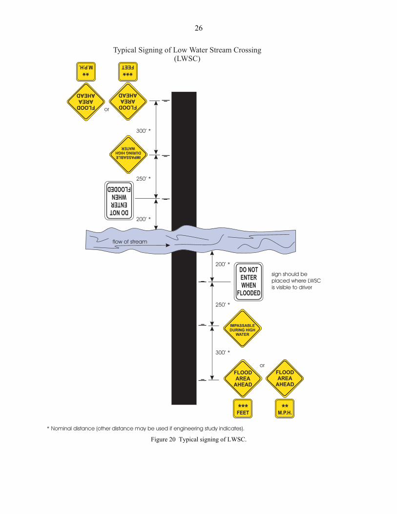
26
Figure 20 Typical signing of LWSC.

27
6 LEGAL CONSIDERATIONS
Potential liability for actions and inactions is always a major concern for local agencies,especially county engineers. Low water stream crossings may raise particular interest sincedesign criteria do not conform with Iowa Department of Transportation standards for bridges andculverts. The Code of Iowa in Section 309.79 seems to imply that all bridges and culvertscomply with standards specifications furnished to local agencies by the department. Section309.74 states that culverts shall allow a minimum clear roadway width of 20 ft and bridge widthof 16 ft. LWSCs can easily be designed to comply with Section 309.74 but Section 309.79seems more problematic.
However, the Code further allows considerable flexibility to boards of supervisors andcounty engineers to carry out responsibilities for the secondary road system. Section 309.57,area service classification, establishes authority for Boards to establish reduced maintenancelevels for certain roads under their jurisdiction. Further, it has long been recognized that localagencies must prioritize available funding to best meet the needs of public transportation. Lowwater stream crossings, designed, constructed, and maintained to reasonable guidelines wouldseem to meet these responsibilities.
A 1981 research report by R. L. Carstens, et al. (1981), Liability and Traffic ControlConsiderations for Low Water Stream Crossings, studied the legal implications in the use ofLWSCs and concluded that, with adequate warning of the existence of such a structure, thepotential for accidents and subsequent tort claims may actually be decreased by LWSCs overdeficient and obsolete bridges. A description of recommended traffic control signing is includedin this report (Section 5).
The survey of county engineers undertaken as part of this research project indicated theexistence of over 225 LWSCs in Iowa, some for approximately 20 years or more. In addition,only three counties advised of tort claims relating to LWSCs. Of these, two counties were foundnot at fault for crashes that occurred at existing crossings. The third claim was filed alleging aright of way issue not directly relating to the LWSC and the county settled out of court. Basedon this history, it would seem that potential liability from the use of LWSCs is not extensive inIowa.
To minimize exposure to tort liability, local agencies using low water stream crossingsshould consider adopting reasonable selection and design criteria and certainly provide adequatewarning of these structures to road users. The design recommendations included in this reportfor LWSCs provide guidelines and suggestions for local agency reference.

28
7 REFERENCES
Berg, B.M. Shoreline Erosion on Selected Artificial Lakes in Iowa. M.S. Thesis, Department ofCivil Engineering, Iowa State University, Ames, 1980.
Carstens, R.L., et al. Liability and Traffic Control Considerations for Low Water StreamCrossings. Department of Civil and Construction Engineering, Iowa State University,Ames, 1981.Gaylord, E.H., and C.N. Gaylord. Structural Engineering Handbook. 2nd ed. McGraw-Hill Book
Co., New York, 1979.Gupta, R.S. Hydrology and Hydraulic Systems. 2nd ed. Waveland Press, Inc., Prospect Heights,
Illinois, 2001.Haestad Methods. Computer Applications in Hydraulic Engineering. Third Edition, Haestad
Methods, Inc., Haestad Methods Press, 1999.Herr, L.A., and H.G. Bossy. Hydraulic Charts for the Selection of Highway Culverts. Hydraulic
Engineering Circulation No. 5, GPO, Washington, D.C., 1965.Isbash, S.V. Construction of Dams by Depositing Rock in Flowing Water. Proc. Second
Congress on Small Dams, Washington, D.C., pp. 123-136, 1936.Keown, M.P., N.R. Oswalt, and E.B. Perry. Literature Survey and Preliminary Evaluation of
Streambank Protection. WES Report RE-H-77-9, Army Engineer Waterways ExperimentStation, Vicksburg, 1977.
Klaiber, F.W., T.J. Wipf, J.R. Reid, and M.J. Peterson. Investigation of Two Bridge Alternativesfor Low Volume Roads . Iowa Department of Transportation, Project No. HR-382, 1997.
Lara, O.G. Annual and Seasonal Low-flow Characteristics of Iowa Streams. Iowa DNRBulletin No. 13, U.S. Geological Survey, Iowa City, 1979.
Larimer, O.J. Drainage Areas of Iowa Streams. Iowa Highway Research Board Bulletin No. 7,U.S. Geological Survey, Iowa City, 1957.
Looschen, M., and D.D. Coy. Hydrologic and Hydraulic Considerations for Low WaterCrossings. Office of Bridge Design, Iowa Department of Transportation, 1982.
Motayed, A.K., F.M. Chang, and D.K. Mukherjee. Design Guide: Low Water Stream Crossing.Federal Highway Administration Report No. FHWA/RD-82/164, U.S. Department ofTransportation, 1982.
Motayed, A.K., F.M. Chang, and D.K. Mukherjee. Design and Construction of Low WaterStream Crossings. Federal Highway Administration Report No. FHWA/RD-83/015, U.S.Department of Transportation, 1983.
Normann J.M., R.J. Houghtalen, and W.J. Johnston. Hydraulic Design of Highway Culverts. USDept. of Transportation Report No. FHWA-IP-85-15, Hydraulic Design Series No. 5, 1985.
Rossmiller, R.L., R.A. Lohnes, S.L. Ring, J.M. Phillips, B.C. Barrett. Design Manual for LowWater Stream Crossings. Iowa Department of Transportation, Project No. HR-247, 1984.
Rice, C.E., K.M. Robinson, K.C. Kadavy. Rock riprap for grade control, North American Waterand Environmental Congress, American Society of Civil Engineers, 1996.
U.S. Department of Transportation. Design charts for Open-Channel Flow. Federal HighwayAdministration, Washington, D.C.
Voegele, D.M. The evaluation of riprap and low-cost grade control structures in western Iowa,Unpublished M.S. Thesis, Iowa State University, Ames, 1997.

29
8 ACKNOWLEDGEMENTS
The authors gratefully acknowledge the following county engineers who generously providedvaluable information based on their first hand experience with LWSCs. The advisory committeeconsisted of Gary Bishop, Todde Folkerts, Tom Goff, John Goode, Mike Olson, and Tom Stoner.Meetings during field trips with Gerry Petermeier, Lyle Brehm, Mike Olson, Dan Ahart, andMyron Parizek provided additional useful insights.
List of Additional Contacts
Dennis Osipowicz, Lee County Engineer
Steve Parks, Davis County
Danny Waid, Howard County Engineer
Christy Van Buskirk, Keokuk County Engineer
Keith Kruger, National Park Service, Omaha, Nebraska
Peter Bolander, USDA Forest Service, Oregon
Terry Jorgenson, South Dakota Department of Transportation
Amir Sortani, Nevada Department of Transportation
Richard Lusardy, WilsonÕs Creek Park, Missouri
Gary Sullivan, WilsonÕs Creek National Park, Missouri
LeRoy Bergmann, Iowa Department of Transportation
Curtis Monk, Federal Highway Administration, Ames

30
APPENDIX A: 2001 SURVEY ON THE USE OF LOW WATER STREAM CROSSINGS
1. Does your county have any low water stream crossings (LWSCs) in service?q YesIf yes, how many on the following:
service level roads A? _____ B?_____ C?_____aggregate-surfaced roads?_____other roads?_____
q No (if no, please skip to question 6)
2. Has your county constructed any LWSCs under your supervision?q Yesq NoIf yes,a. Were your LWSCs constructed
q by contract?q in-house?
b. What did you use as design standards?q Existing references (please list source)q In-house design (describe or provide copy)
c. Do you consider drainage area and/or streambed gradient in your design?Drainage area Streambed gradientq Yes ¾ Yesq No ¾ No
3. What type of LWSC do you prefer?(please rank in order of preference)_____ With pipe/s_____ Without pipe_____ Beam in slab_____ Other, please describe
4. Has your county ever been involved in a tort liability claim or lawsuit over the use ofLWSCs?q Yesq NoIf yes, may we contact you for more information about liability claims?q Yesq NoName, Phone: __________________________________________________
5. In your experience with LWSCs, are there any practices/situations you would recommendothers to avoid?

31
6. Would you benefit from an easy-to-use design manual for LWSCs?q Yesq No
7. What topics would you recommend for such a manual?
8. If you had access to a user-friendly manual, would you be more likely to specify LWSCsas low cost substitutes for bridges and/or culverts under appropriate and applicableconditions?q Yesq No
9. May we contact you for more information about your experiences with LWSCs?q Yesq NoName, Phone: _________________________________________________
-------------------------------------------------------------------------------------------------------Please return the completed survey by May 15, 2001.
32
APPENDIX B: SUMMARY OF SURVEY RESPONSES
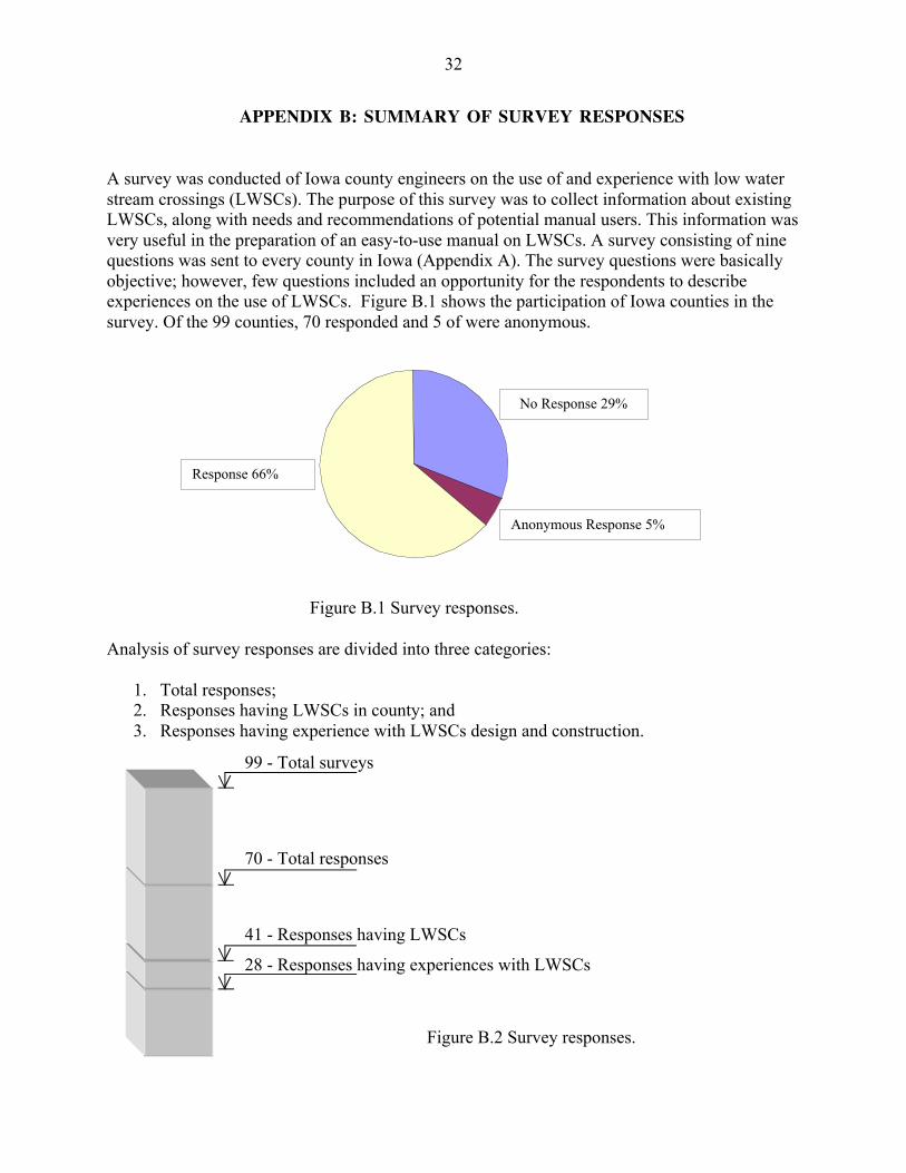
A survey was conducted of Iowa county engineers on the use of and experience with low waterstream crossings (LWSCs). The purpose of this survey was to collect information about existingLWSCs, along with needs and recommendations of potential manual users. This information wasvery useful in the preparation of an easy-to-use manual on LWSCs. A survey consisting of ninequestions was sent to every county in Iowa (Appendix A). The survey questions were basicallyobjective; however, few questions included an opportunity for the respondents to describeexperiences on the use of LWSCs. Figure B.1 shows the participation of Iowa counties in thesurvey. Of the 99 counties, 70 responded and 5 of were anonymous.
Analysis of survey responses are divided into three categories:
1. Total responses;2. Responses having LWSCs in county; and3. Responses having experience with LWSCs design and construction.
Figure B.2 Survey responses.
Response66%
70 - Total responses
41 - Responses having LWSCs
28 - Responses having experiences with LWSCs
99 - Total surveys
Figure B.1 Survey responses.
No Response 29%
Response 66%
Anonymous Response 5%

33
Figure B.2 presents an overall summary of survey responses. Among 70 responses, 41 haveLWSCs in their counties, but only 28 engineers indicated having experience with the design andconstruction. The results and discussion are therefore presented in these three categories.
LWSCs in service (Question 1)
More than 226 LWSCs are found in 36 counties (Figure B.3). This estimate is quite close to theresult from a survey conducted in 1984, where a total of 220 LWSCs in 42 counties wasindicated (Rossmiller et al., 1984). Most of LWSCs are found located in Service Level B roads.Considering the earlier results, it is possible that many more LWSCs exist than were indicated bythe current survey.
21+
145+
4+
47+
9+
226+
0
50
100
150
200
250
Service roadsA
Service roadsB
Service roadsC
Aggregate-surfaced roads
Other roads Total LWSCs
Nu
mb
er o
f L
WS
Cs
Figure B.3 Number of LWSCs on different types of roads (Question 1).
34
Experience with LWSCs design and construction (Question 2)
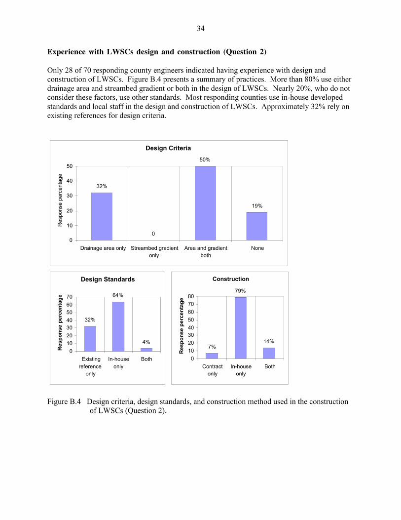
Only 28 of 70 responding county engineers indicated having experience with design andconstruction of LWSCs. Figure B.4 presents a summary of practices. More than 80% use eitherdrainage area and streambed gradient or both in the design of LWSCs. Nearly 20%, who do notconsider these factors, use other standards. Most responding counties use in-house developedstandards and local staff in the design and construction of LWSCs. Approximately 32% rely onexisting references for design criteria.
Design Criteria
0
32%
50%
19%
0
10
20
30
40
50
Drainage area only Streambed gradientonly
Area and gradientboth
None
Res
pons
e pe
rcen
tage
Design Standards
4%
64%
32%
0
10
20
3040
50
60
70
Existingreference
only
In-houseonly
Both
Res
po
nse
per
cen
tag
e
Construction
14%
79%
7%
0
10
20
3040
50
60
70
80
Contractonly
In-houseonly
Both
Res
po
nse
per
cen
tag
e
Figure B.4 Design criteria, design standards, and construction method used in the constructionof LWSCs (Question 2).

35
Preferences on LWSC types (Question 3)
Preferred type of LWSCs found that vented (piped) crossings are most popular (Figure B.5).
Legal experience with LWSCs (Question 4)
Only three responding counties indicated experiencing tort liability claims with the use ofLWSCs: Howard, Keokuk, and Jefferson. Further discussion on this topic can be found in theliability section of this report.
Suggestions on the use of LWSCs (Question 5)
Many responding counties related experiences with LWSCs and made recommendations. Themain points are summarized below:
1. Avoid LWSCs:· With small diameter pipes; clogging problem.· In deep channels; approaches washing out.· At crossings with skew angles above 10-15 degrees; scouring problem.· On loess soils; instability.· In dead end roads with residences at end.
2. LWSC suitable locations:· With pipe/s: Small streams with defined channel and good fit with approaches
25
865 4
7
1
7
2
0
5
10
15
20
25
30
With pipe/s Without pipe Beam in slab
Nu
mb
er o
f p
refe
ren
ces
1st 2nd 3rd preference
Figure B.5 Preferences on several types of LWSCs (Question 3).

36
· Without pipe: Low roads near river prone to flooding· Beam in slab: Deeper channel and large drainage area· On very low traffic roads and where land access is necessary· In ephemeral streams· On Class C roads due to liability concerns· Road alignment should allow for a straight entry
3. Additional considerations:· Gradual crossing slope into and out of the stream.· Use of design storm to base hydraulics on (at least 5 years frequency event).· Protection of side slopes.· Undulations in roads due to LWSCs construction.· Posting of traffic signs and signals at positions well ahead of crossing.· Make area 200-300 ft either side of Class B roads.
Benefit from a LWSCs manual (Question 6)
Figure B.6 displays the interest of Iowa counties in a design manual for LWSCs. Forty-sevencounties are interested, of which 29 have experience with LWSCs. Several counties not havingLWSCs are not interested in a manual. Note that the availability of an improved, complete, andeasy-to-use manual could influence additional use.
47
20
1
29
9
0
18
11
1
0
5
10
15
20
25
30
35
40
45
50
Interested Not interested No response
Use
of
LW
SC
s m
anu
al
Total Reponses having LWSCs Responses not having LWSCs
Figure B.6 Support for the use of LWSCs manual (Question 6).

37
Suggestion of topics for manual (Question 7)
More than half of the respondents suggested topics for a design manual. Table B.1 lists theseunder several categories. This information provides good insight for useful manual contents.Liability concerns were found to be of equal importance with design considerations.
Table B.1 Discussion topics suggested for LWSCs manual (Question 7).
Category Topics
Liabilities1. Thorough discussion of associated liabilities2. How LWSCs compromise public safety?3. Example of a legal case concerning LWSC
Design
1. Construction procedures2. Structural design details:
· Paving requirements· Riprap size· Fore slope recommendations· Depth of sheet wall· Side slope protection (shotcrete, matting, vegetation,
etc.)· Geometric of crossings· Materials
3. Maintenance considerations4. ADT design guidelines
Design criteria
1. Best circumstances to use LWSCs based on· Drainage area· Slope· Approach heights· Channel shapes· Regions· Level of service, road type
2. Application of LWSCs in winter3. When to change roadway grade?4. When to use LWSCs instead of others like ADT, etc.?
Signing Proper and legal signing
Miscellaneous1. What backwater effects are created?2. Benefit-cost information compared to culverts and bridges.

38
Support for LWSCs applications in Iowa counties if manual were available (Question 8)
More than 70% of respondents would consider LWSC structures as low-cost substitutes forbridges and/or culverts under appropriate and applicable conditions (Figure B.7). Uninterestedcounties having no experience with LWSCs structures may be motivated to consider this optionif an easy to use manual were provided.
49
18
1
32
8
0
17
10
1
0
10
20
30
40
50
60
Yes No No response
LW
SC
s ap
plic
atio
ns
Total Responses having LWSCs Responses not having LWSCs
Figure B.7 Support for LWSCs applications (Question 8).

39
APPENDIX C: MANNINGÕS ROUGHNESS COEFFICIENT (N) FOR NATURALSTREAM CHANNELS
1. Fairly regular section:a. Some grass and weeds, little or no brushb. Dense growth of weeds, depth of flow materially greater than
weed heightc. Some weeds, light brush on banksd. Some weeds, heavy brush on bankse. Some weeds, dense willows on banksf. For trees within channel, with branches submerged at high
stage, increase all above values by2. Irregular section, with pools, slight channel meander; increase
values given above about3. Mountain streams, no vegetation in channel, banks usually steep,
trees and brush along banks submerged at high stage:a. Bottom of gravel, cobbles, and few bouldersb. Bottom of cobbles, with large boulders
0.03 - 0.035
0.035 - 0.050.035 - 0.050.05 - 0.070.06 - 0.08
0.01 - 0.02
0.01 - 0.02
0.04 - 0.050.05 - 0.07
Source: U.S. Department of Transportation
40
APPENDIX D: DESIGN OF A VENTED FORDÑSIZE AND NUMBER OF PIPES
D.1 Design Curves (D vs. Qvent)
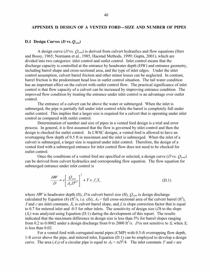
A design curve (D vs. Qvent) is derived from culvert hydraulics and flow equations (Herrand Bossy, 1965; Normann et al., 1985, Haestad Methods, 1999; Gupta, 2001), which aredivided into two categories: inlet control and outlet control. Inlet control means that thedischarge capacity is controlled at the entrance by headwater depth (HW) and entrance geometry,including barrel shape and cross-sectional area, and the type of inlet edges. Under the inletcontrol assumption, culvert barrel friction and other minor losses can be neglected. In contrast,barrel friction is the predominant head loss in outlet control situation. The tail water conditionhas an important effect on the culvert with outlet control flow. The practical significance of inletcontrol is that flow capacity of a culvert can be increased by improving entrance condition. Theimproved flow condition by treating the entrance under inlet control is an advantage over outletcontrol.
The entrance of a culvert can be above the water or submerged. When the inlet issubmerged, the pipe is partially full under inlet control while the barrel is completely full underoutlet control. This implies that a larger size is required for a culvert that is operating under inletcontrol as compared with outlet control.
Determination of number and size of pipes in a vented ford design is a trial and errorprocess. In general, it is first assumed that the flow is governed by inlet control and then thedesign is checked for outlet control. In LWSC designs, a vented ford is allowed to have anovertopping flow depth of 0.5 ft in maximum and the inlet is submerged. When the inlet of aculvert is submerged, a larger size is required under inlet control. Therefore, the design of avented ford with a submerged entrance for inlet control flow does not need to be checked foroutlet control.
Once the conditions of a vented ford are specified or selected, a design curve (D vs. Qvent)can be derived from culvert hydraulics and corresponding flow equation. The flow equation forsubmerged entrance under inlet control is
osb
vent SfYDA
Qc
DHW
++úû
ùêë
é=
2
5.0 (D.1)
where HW is headwater depth (ft), D is culvert barrel size (ft), Qvent is design dischargecalculated by Equation (8) (ft3/s, i.e. cfs), Ab = full cross-sectional area of the culvert barrel (ft2),Y and c are inlet constants, So is culvert barrel slope, and fs is slope correction factor that is equalto 0.7 for mitered inlet and -0.5 for other inlets. The sensitivity of design size (D) to the slope(So) was analyzed using Equation (D.1) during the development of this report. The resultsindicated that the maximum difference in design size is less than 5% for barrel slopes rangingfrom 0.2 to 0.0002 under a design discharge from 0 to 2000 ft3/s. D is not sensitive to So when So
is less than 0.02.For a vented ford with corrugated metal pipes (CMP) with 0.5-ft overtopping flow depth,
1-ft cover above the pipe, and mitered inlet, Equation (D.1) can be employed to develop a designcurve. The area (A b) of a circular pipe is equal to Ab = pD2/4. The inlet constants Y and c are

41
0.75 and 0.0463, respectively, for CMP culverts with a mitered entrance (Herr and Bossy, 1965;Normann et al., 1985; Haestad Methods, 1999). The headwater is equal to D plus pipe cover (1ft) and overtopping flow depth at the entrance (0.5 ft/0.6 = 0.83 ft). Equation (D.1) can berewritten as
2/15.2 7.025.0
83.165.3 ÷
ø
öçè
æ -+= ovent SD
DQ (D.2)
The design curve (D vs. Qvent) shown in Figure 11 is obtained by plotting Equation (D.2) for theconditions specified above and a pipe slope of 0.02 or less.
D.2 HEC-5 charts
Existing HEC-5 charts (Herr and Bossy, 1965; Normann et al., 1985) may also be used forvented ford design. The monographs were developed from the culvert hydraulics and flowequations described above (Section D.1) for various types and conditions, including flowcontrols (inlet or outlet), barrel shapes, barrel materials, and inlet treatments, etc.
To use the charts for a vented ford design, design flow through the vent (Qvent) is firstdetermined from Equation (8) and a chart is then selected for specific inlet submergence, flowcontrol, barrel shape and material, and inlet treatment, etc. Following steps are taken in thedesign:
1) Assume a size (Da) of the vent (pipe diameter or box width). As a reference for the firsttrial, use Da = 2(Qvent/20)1/2
2) Calculate the allowable headwater depth HW = H + P, where H = h/0.6 = 0.833 if h isdesigned as 0.5 ft (Figure 9(a)). Calculation of P requires consideration of cover depthabove pipes. If a pipe cover depth of 1 ft is used, P = Da + 1. Then, HW = 1.833 + Da
3) On the monograph as shown in Figure D.1, which is for a submerged inlet, corrugatedmetal pipes and inlet control flow, connect the point of Da value to that of the givendischarge (Qvent) and extend the line to read the ratio HW/Dc value on scale (2) for mitered(beveled) entrance, where Da is the assumed pipe size and Dc is the calculated pipe size.Charts for other types of vents with different flow control, barrel shape, pipe material, andentrance treatment are provided in Herr and Bossy (1965) and Normann et al. (1985).
4) Compute Dc using HW calculated in step (2) and ratio HW /Dc determined in step (3),Dc = HW /(HW /Dc)
5) If the computed size, Dc, is not equal or close enough to that originally assumed, Da,repeat the procedure by assuming a new Da. If Dc > Da, assume a smaller Da and if Dc < Da use a greater Da for the next trial.
6) If any trial size is too large in dimension because of limited height of LWSC or availabilityof pipe size, multiple culverts may be used by dividing the discharge equally between the

42
numbers of barrels used. Raising the LWSC height or the use of pipe arch and box culvertswith width greater than height can also be considered.
7) If the selected design size is too small (less than 12 inches), the recommended minimumsize should be used.
D.3 Computer programÑCulvertMaster
This commercial computer model was developed by Haestad Methods (1999) and is based on theculvert hydraulics and flow equations (Herr and Bossy, 1965; Normann et al., 1985; HaestadMethods 1999) described above (Section D.1). As a convenient design tool, the model providesquick culvert calculations and detailed analyses. The computer program can be purchasedthrough the internet at www.haestat.com.

43
Dis
char
ge(Q
e)in
cfs
Figure D.1 Headwater depth for C.M. pipe culverts with inlet control—Chart #5 of HEC-5 charts in Herr and Bossy (1965).
Note: Figure D.1 is valid only for submerged inlet, corrugated metal pipes and inletcontrol flow. Charts for other types of vents with different flow control, barrel shape, pipematerial, and entrance treatment are provided in Herr and Bossy (1965) and Normann etal. (1985).

44
APPENDIX E: DESIGN EXAMPLES
General design criteria listed below are used in these design examples. Where different criteriaare used, these are specified in each individual example.
For all fords:Allowable flow depth over LWSC: h = 0.5 ftAcceptable percent of time closed: e = 2%
For unvented fords:Maximum height of LWSC above streambed: P £ 4 ft
For vented fords:Minimum pipe size: 1 ftAbove-pipe cover: 1 ft
E.1 Example One
DataLWSC site: Shelby County, Region IIDrainage area (Larimer, 1957): A = 5.02 mile2
Stream slope: S = 0.0013Streambed roughness: n = 0.04Stream width: w = 20 ft
CriteriaAcceptable percent of time closed: e = 10%
Design
1. Design discharge. For 10% allowable closing time, the design discharge is determinedfrom the equation in Figure 7:
Qe = 4.57 cfs
2. Unvented ford on channel bottom (h = H), using Equation (3):
5/3
2/1486.1÷ø
öçè
æ=
wS
nQH e = 0.35 ft
This simplified equation is valid since w/H = 20/ 0.35 = 57, which is greater than 10 (seeSection 3.2.1.1 and Equation (2)). Flow depth, h = 0.35 ft, is less than designrequirement (£ 0.5 ft). Therefore, a ford on the channel bottom is acceptable.

45
E.2 Example Two
DataLWSC site: Shelby County, Region IIDrainage area (Larimer, 1957): A = 6.32 mile2
Stream slope: S = 0.0060Streambed roughness: n = 0.04Stream width: w = 20 ft
Design
1. Design discharge for a 2% exceedence probability. The design discharge is determinedfrom the equation in Figure 7:
Qe = 35.63 cfs
2. Unvented ford on channel bottom (h = H), using Equation (3):
5/3
2/1486.1÷ø
öçè
æ=
wS
nQH e = 0.75 ft
This simplified equation is valid since w/H = 20/ 0.75 = 27 which is greater than 10.Flow depth, h = 0.75 ft, is greater than design requirement (£ 0.5 ft). Therefore, a fordon the channel bottom is not acceptable.
3. Raised unvented ford (L = 20 ft, P = 2-4 ft), using Equation (6):
493.0599.0233.0 -= LQh e = 0.45 ft, less than 0.5 ft, acceptable.
E.3 Example Three
DataLWSC site: Located in Region II of IowaDrainage area: A = 40 mile2
Stream slope: S = 0.0019Streambed roughness: n = 0.04Stream width: w = 50 ft
Design1. Design discharge. For 2% allowable closing time, the design discharge can be determined
from the equation in Figure 7, Qe = 6.78A0.9:
Qe = 188 cfs

46
2. Unvented ford on channel bottom (h = H), using Equation (3):
5/3
2/1486.1÷ø
öçè
æ=
wS
nQH e = 1.658 ft
This simplified equation is valid since w/H = 50/1.658 = 30, which is greater than 10.Flow depth, h = 1.658 ft, is greater than design requirement (£ 0.5 ft). Therefore, a fordon the channel bottom is not acceptable.
3. Raised unvented ford (L = 50 ft, P = 2-4 ft), using Equation (6):
493.0599.0233.0 -= LQh e = 0.8 ft, greater than 0.5 ft, not acceptable.
4. Vented ford (corrugated metal pipe with inlet control and mitered entrance):
823.0538.3 LQtop = = 88 cfs Equation (10)
topevent QQQ -= = 188 Ð 88 = 100 cfs Equation (8)
a. Using a design curve (see Section D.1). The required pipe size can be obtained fromthe design curves shown in Figure 11. Recommended pipe diameters are 4 ft if a singlepipe is used (Qvent = 100 cfs), 3 ft each for two pipes (Qvent = 50 cfs), 2 ft for five pipes(Qvent = 20 cfs), and 1.5 ft for ten pipes (Qvent = 10 cfs).
b. Using HEC-5 charts (see Section D.2 and Figure D.1)
For a single pipe, Qvent = 100 cfs. Use Da = 2(Qvent/20)1/2 = 4.5 ft as a reference trial.Da (ft) Da (in) P (ft) HW (ft) HW /Dc Dc (ft) êDc-Daê/Da
3.5 42 4.5 5.33 2.43 2.19 0.3734 48 5 5.83 1.5 3.94 0.0154.5 54 5.5 6.33 1.02 6.20 0.378
Select 4 ft as the design size.
For two pipes, Qvent = 50 cfs. Use Da = 2(Qvent/20)1/2 = 3.2 ft as a reference trial.Da (ft) Da (in) P (ft) HW (ft) HW /Dc Dc (ft) êDc-Daê/Da
2.5 30 3.5 4.58 3.2 1.43 0.4283 36 4 4.83 1.6 3.0 0.03.5 42 4.5 5.33 0.98 5.4 0.54
Select 3 ft as the design size and use two pies.

47
For five pipes, Qvent = 20 cfs. Use Da = 2(Qvent/20)1/2 = 2.0 ft as a reference trial.Da (ft) Da (in) P (ft) HW (ft) HW /Dc Dc (ft) êDc-Daê/Da
1.75 21 2.75 3.58 3.3 1.09 0.382 24 3 3.83 1.93 1.98 0.00782.25 27 3.25 4.08 1.27 3.21 0.43
Select 2 ft as the design size and use five pipes.
For ten pipes, Qvent = 10 cfs. Use Da = 2(Qvent/20)1/2 = 1.4 ft as a reference trial.Da (ft) Da (in) P (ft) HW (ft) HW /Dc Dc (ft) êDc-Daê/Da
1.25 15 2.25 3.08 4.8 0.64 0.4881.5 18 2.5 3.33 2.1 1.59 0.061.75 21 2.75 3.58 1.2 2.98 0.70
Select 1.5 ft as the design size and use ten pipes.
In summary, this vented ford would require one 4-ft pipe, two 3-ft pipes, five 2-ft pipes,or ten 1.5-ft pipes.
5. Pipe exit velocity, using Equation (11):
Ve = Q/(3.1417 D2/4)
Computed exit velocities are 9.1, 7.1, 6.4, and 5.7 ft/s for one pipe (4 ft), two pipes (3 ft), fivepipes (2 ft) and ten pipes (1.5 ft), respectively, all less than the 10 ft/s limit to prevent scour ofchannel.
E.4 Example Four
DataLWSC site: Benton County, Region IDrainage area: A = 150 mile2
Stream slope: S = 0.0015Streambed roughness: n = 0.04Stream width: w = 80 ft
Design
1. Design discharge for a 2% exceedence probability. The design discharge is determinedfrom the equation in Figure 6:
Qe = 616.19 cfs
2. Unvented ford on channel bottom (h = H), using Equation (3):
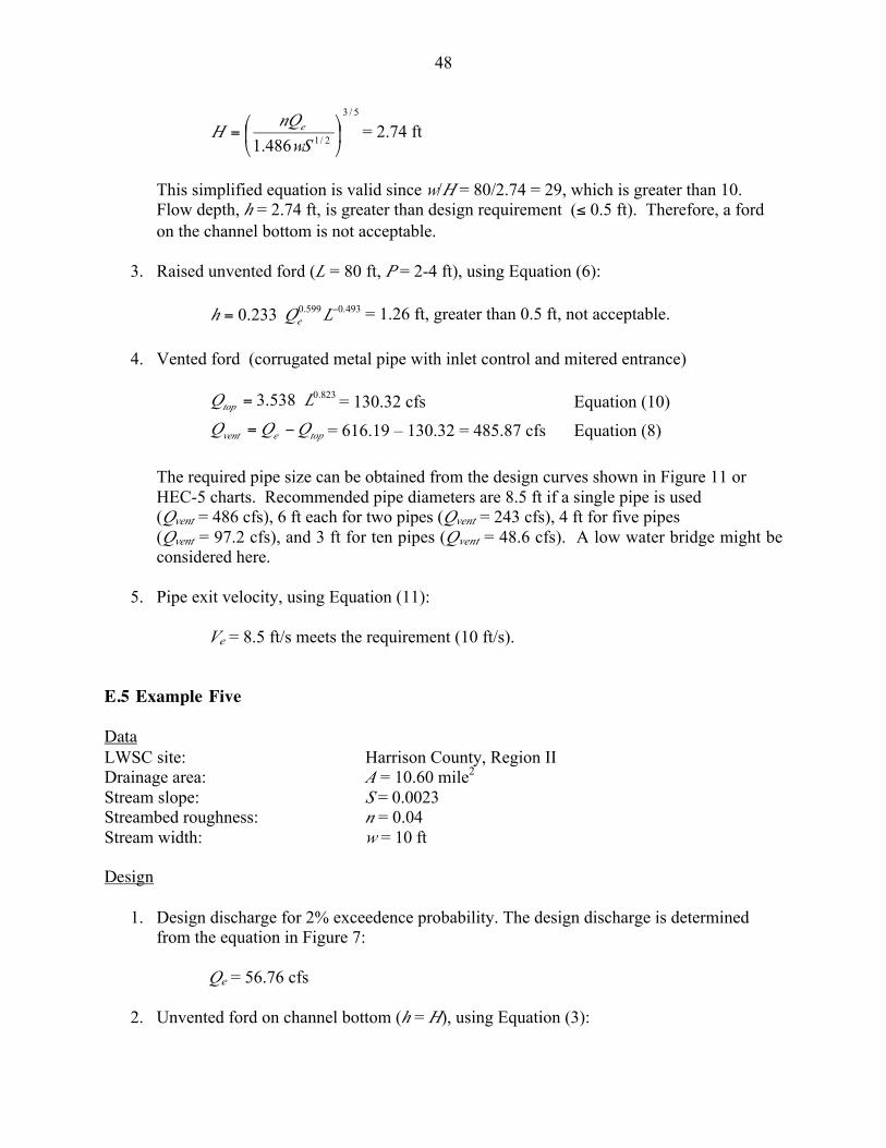
48
5/3
2/1486.1÷ø
öçè
æ=
wS
nQH e = 2.74 ft
This simplified equation is valid since w/H = 80/2.74 = 29, which is greater than 10.Flow depth, h = 2.74 ft, is greater than design requirement (£ 0.5 ft). Therefore, a fordon the channel bottom is not acceptable.
3. Raised unvented ford (L = 80 ft, P = 2-4 ft), using Equation (6):
493.0599.0233.0 -= LQh e = 1.26 ft, greater than 0.5 ft, not acceptable.
4. Vented ford (corrugated metal pipe with inlet control and mitered entrance)
823.0538.3 LQtop = = 130.32 cfs Equation (10)
topevent QQQ -= = 616.19 Ð 130.32 = 485.87 cfs Equation (8)
The required pipe size can be obtained from the design curves shown in Figure 11 orHEC-5 charts. Recommended pipe diameters are 8.5 ft if a single pipe is used(Qvent = 486 cfs), 6 ft each for two pipes (Qvent = 243 cfs), 4 ft for five pipes(Qvent = 97.2 cfs), and 3 ft for ten pipes (Qvent = 48.6 cfs). A low water bridge might beconsidered here.
5. Pipe exit velocity, using Equation (11):
Ve = 8.5 ft/s meets the requirement (10 ft/s).
E.5 Example Five
DataLWSC site: Harrison County, Region IIDrainage area: A = 10.60 mile2
Stream slope: S = 0.0023Streambed roughness: n = 0.04Stream width: w = 10 ft
Design
1. Design discharge for 2% exceedence probability. The design discharge is determinedfrom the equation in Figure 7:
Qe = 56.76 cfs
2. Unvented ford on channel bottom (h = H), using Equation (3):

49
Flow depth, h = 2.0 ft, is greater than design requirement (£ 0.5 ft). Therefore, a ford onthe channel bottom is not acceptable.
3. Raised unvented ford (L = 10 ft, P = 2-4 ft), using Equation (6):
493.0599.0233.0 -= LQh e = 0.84 ft, greater than 0.5 ft, not acceptable.
4. Vented ford (corrugated metal pipe with inlet control and mitered entrance)
823.0538.3 LQtop = = 23.54 cfs Equation (10)
topevent QQQ -= = 56.76 Ð 23.54 = 33.22 cfs Equation (8)
The required pipe size can be obtained from the design curves (Figure 11) or HEC-5charts. Recommended pipe diameters are 2.25 ft if a single pipe is used and 1.75 ft fortwo pipes.
5. Exit velocity (8.3 f/s) is acceptable, using Equation (11).
E.6 Example Six
DataLWSC site: Key Creek, Harrison CountyDrainage area: A = 30.4 mile2
Stream slope: S = 0.012Streambed roughness: n = 0.04Stream width: w = 30 ft
CriteriaAbove-pipe cover: 2 ft
Design
1. Design discharge for 2% exceedence probability. The design discharge is determinedfrom the equation in Figure 7:
Qe = 146.49 cfs
2. Unvented ford on channel bottom (h = H), using Equation (3):
Flow depth, h = 1.56 ft, is greater than design requirement (£ 0.5 ft). Therefore, a fordon the channel bottom is not acceptable.

50
3. Raised unvented ford (L = 30 ft, P = 2-4 ft), using Equation (6):
493.0599.0233.0 -= LQh e = 0.86 ft, greater than 0.5 ft, not acceptable.
4. Vented ford (corrugated metal pipe with inlet control and mitered entrance)
823.0538.3 LQtop = = 58.13 cfs Equation (10)
topevent QQQ -= = 146.49 Ð 58.16 = 88.36 cfs Equation (8)
The required pipe size is obtained from Equation (D.2) or HEC-5 charts. With a cover of2 ft above the pipe, Equation (D.2) is modified to
2/15.2 7.025.0
83.265.3 ÷
ø
öçè
æ -+= ovent SD
DQ
Substituting So = 0.012 and Qvent = 88.36 and solving for D, the required pipe diameter isobtained as 3.5 ft. If using two pipes, the size would be 2.5 ft each. For three pipes, thedesign diameter is 2 ft each. The above equation could be plotted and used as a designcurve for vented fords with a pipe cover of 2 ft.
5. Exit velocity (9.1 f/s) is acceptable, using Equation (11).