lp 280 rotary screw nitrox factory - nuvair.com
TRANSCRIPT
Nit
Operation Manual
LP 280 rox GeneratorTM
Gardner Denver/Bottarini Version
LP 280 Nitrox GeneratorTM If you have any questions on this equipment please contact Technical Support at:
Nuvair 2949 West 5th St. Oxnard, CA 93030 Phone: 805-815-4044 FAX: 805-815-4196 Email: [email protected] Hours: Monday through Friday
8:00 AM to 5:00 PM PST USA
WARNING This Operation Manual contains important safety information and should always be available to those personnel operating this equipment. Read, understand, and retain all instructions before operating this equipment to prevent injury or equipment damage.
Every effort was made to ensure the accuracy of the information contained within. Nuvair, however, retains the right to modify its contents without notice. If you have problems or questions after reading the manual, stop and call for information.
NUVAIR Page 2 LP 280 Nitrox Generator Operation Manual

LP 280 Nitrox GeneratorTM Table of Contents
Introduction 1.0 Introduction …………………………………….................................................................................... 4 2.0 Safety Warnings System Components …………………………………….......................................... 5 3.0 Safety and Operation Precautions ……………………………………................................................. 6 4.0 Legal Precautions …………………………………….......................................................................... 7 5.0 Theory of Operation ……………………………………....................................................................... 8 6.0 Low Pressure Rotary Screw Compressor Technical Data …………………………………………...... 9 7.0 System Components ……………………………………………………………………………………….. 10 8.0 Nitrox System Specifications ……………………………………......................................................... 11 9.0 Component Identification ……………………………………………………..………………………….... 12 10.0 System Drawing/Schematic ………………………………………………………………………………. 13 11.0 System Flow Chart ………………………………………………………………………………………… 14 Setup, Operation, and Maintenance 12.0 Preparing Existing HP Compressors ……………………………………............................................. 15
12.1 Purification System Air/Nitrox Quality ……………………………………................................ 15 12.2 Replacement of Compressor Lubricant ……………………………………............................ 15 12.3 Installation of Fill Oxygen Analyzer …………………………………….................................. 16
13.0 Installing the Nitrox System …………………………………….......................................................... 17 13.1 Precautions ……………………………………...................................................................... 17 13.2 Attaching the Air Supply ……………………………………................................................... 17 13.3 Attaching Compressor Intake Hose ……………………………………................................. 18 13.4 Attaching Nitrogen Discharge Hose (Optional) ……………………………………................ 18 13.5 Output Pressure Adjustments …………………………………….......................................... 19 13.6 Electrical Power Connection ……………………………………............................................ 19 13.7 Air/Nitrox Quality Testing ………………………………………………………………………… 20
14.0 Pre-Operation Instructions ……………………………………............................................................ 21 14.1 Compressor Oil Levels ……………………………………..................................................... 21 14.2 Membrane System Regulator and Flow Valve ……………………………………................. 21 14.3 Oxygen Analyzer Calibration ……………………………………............................................ 22 14.4 Attaching Scuba Cylinder ……………………………………................................................. 23
15.0 Producing Nitrox ……………………………………............................................................................ 24 15.1 Flow to Membrane ……………………………………........................................................... 24 15.2 Setting Proper Pressure ……………………………………................................................... 25 15.3 Final Adjustments Before Pumping Nitrox ……………………………………....................... 25 15.4 Pumping Nitrox ……………………………………................................................................ 26 15.5 Pumping Air ……………………………………..................................................................... 28 15.6 Shutting Down ……………………………………................................................................. 28
16.0 Nitrox Operation Notes ……………………………………................................................................. 29 16.1 Correlation of Input Pressure to Oxygen Content ……………………………………............ 29 16.2 Hot Fills ……………………………………............................................................................ 29
17.0 Maintenance ……………………………………................................................................................. 30 17.1 Daily Maintenance ……………………………………........................................................... 30 17.2 Routine Maintenance ……………………………………...................................................... 30 17.3 Compressor Lubricant ……………………………………..................................................... 32 17.4 LP Filtration ……………………………………..................................................................... 33 17.5 Spare Parts List ……………………………………............................................................... 34 17.6 Service Record Log ……………………………………......................................................... 35
Appendix ……………………………………................................................................................................... 36
Supply and Breathing Air Specifications ……………………………………...................................... 36 Filter Element Life Factors ……………………………………........................................................... 36 Material Safety Data Sheets ……………………………………........................................................ 37 Owner’s Warranty Responsibilities ……………………………………………………………………... 41 Warranty …………………………………………………………………………………………………… 42
Separate Manuals Included: Nuvair Pro O2 TM Oxygen Analyzer Operation Manual
NUVAIR Page 3 LP 280 Nitrox Generator Operation Manual
Gardner Denver ESE Rotary Screw Compressor Operation & Maintenance Instructions

LP 280 Nitrox GeneratorTM 1.0 Introduction This manual will assist you in the proper set-up, operation and maintenance of the Nuvair LP 280 Nitrox Generator TM. Be sure to read the entire manual. Throughout this manual we will use certain words to call your attention to conditions, practices or techniques that may directly affect your safety. Pay particular attention to information introduced by the following signal words: Indicates an imminently hazardous situapersonal injury or death. Indicates a potentially hazardous situatiopersonal injury or death. Indicates a potentially hazardous situatiomoderate injury. It may also be used to a Notifies people of installation, operation not hazard-related.
NUVAIR LP 280 Nitrox Generator Operation Manual
DANGER
tion, which if not avoided, will result in seriousWARNING n, which if not avoided, could result in serious
CAUTION n, which if not avoided, may result in minor or lert against unsafe practices.NOTICE or maintenance information which is important but
Page 4

LP 280 Nitrox GeneratorTM 2.0 Safety Warnings Nuvair has taken extreme care in providing you with the information you will need to operate this system. However, it is up to you to carefully read this manual and make the appropriate decisions about system safety.
WARNING This equipment is used to provide breathing gas for the purpose of underwater life support. Read this manual in its entirety. Failure to heed the warnings and cautions contained in this document may result in severe injury or death.
WARNING The equipment you will be using to manufacture nitrox (oxygen rich air) will expose you to both low and high-pressure gas. Gas, even under moderate pressures, can cause extreme bodily harm. Never allow any gas stream to be directed at any part of your body.
WARNING Any pressurized hose can cause extreme harm if it comes loose or separates from its restraint (or termination) while under pressure and strikes any part of your body. Use appropriate care in making and handling all gas connections. Pure nitrogen is a colorless, odorless, tasmixtures containing more than 84% nitrogunconsciousness and may cause death.
The nitrogen discharge from the Membraclosed building, boat, or similar enclosed84% nitrogen at surface pressure will lead
Do not use any form of mineral oil or syncompressor in this system. Use only the mix the Nitrox Compressor Lubricant withreplace with the proper Nitrox CompressoThe use of improper lubricants can lead tpersonal injury or death.
NUVAIR LP 280 Nitrox Generator Operation Manual
DANGER
teless gas that will not support life. Breathing gas en at surface pressures will lead toWARNING
ne System must be vented to the exterior of any space. Breathing gas mixtures containing more than to unconsciousness and may cause death.
thetic lubricant not rated for nitrox in any recommended Nitrox Compressor Lubricant. Never other lubricants. Remove all existing lubricant and r Lubricant prior to installing the Membrane System.
o fire or explosions, which may cause serious
WARNING
Page 5

LP 280 Nitrox GeneratorTM
WARNING Do not use this system to produce nitrox mixtures containing more than 40% oxygen. Pumping nitrox mixtures with higher concentrations of oxygen may lead to fires or explosions, which can cause serious personal injury or death.
WARNING The use of enriched air nitrox does not eliminate the risk of decompression sickness (DCS) in diving. Decompression sickness can lead to permanent disability or death.
WARNING Do not pump nitrox mixtures at pressures above the compressor manufacturer’s rating, and never above 3600 P.S.I. (250 bar). The system is not rated for pressures above 3600 P.S.I. (250 bar). Higher pressures may lead to explosions which may cause serious personal injury or death.
WARNING Some compressors are not suitable for compressing oxygen-rich air, i.e., nitrox. Use of an unsuitable compressor may lead to possible compressor damage and/or fires or explosion. This can lead to serious personal injury or death. If there is any doubt regarding the use of an existing compressor, contact Nuvair or the compressor manufacturer before you connect your Membrane System to your machinery. Ambient room temperature should neverSystem. Operation at higher temperaturedamaged membrane will not produce thepersonal injury if the gas is used for divin 3.0 Safety And Operation Precautions Because a Compressor is a piece of machinshould be observed as with any piece of mamaintenance is hazardous to personnel. In alisted below must also be observed: 1) Read all instructions completely before o2) For installation, follow all local electrical a
(NEC) and the Occupational Safety and 3) Electric motors must be securely and ad
with a grounded, metal-clad raceway sysground wire connected to the bare metal
4) Protect all power cables from coming in cnever allow the cables to come in contac
NUVAIR LP 280 Nitrox Generator Operation Manual
CAUTION
exceed 100oF (38oC) during operation of the Nitrox s may lead to system damage and malfunction. A correct nitrox mixture which can lead to severe g purposes without proper analysis.ery with moving and rotating parts, the same precautions chinery of this type where carelessness in operations or ddition to the many obvious safety precautions, those
perating any compressor or Nitrox System. nd safety codes, as well as the National Electrical Code
Health Administration (OSHA) standards. equately grounded. This can be accomplished by wiring tem to the compressor starter; by using a separate of the motor frame; or other suitable means. ontact with sharp objects. Do not kink power cables and t with oil, grease, hot surfaces, or chemicals.
Page 6
LP 280 Nitrox GeneratorTM 5) Make certain that power source conforms to the requirements of your equipment. 6) Pull main electrical disconnect switch and disconnect any separate control lines, if used, before
attempting to work or perform maintenance. “Tag Out” or “Lock Out” all power sources. 7) Do not attempt to remove any parts without first relieving the entire system of pressure. 8) Do not attempt to service any part while System is in an operational mode. 9) Do not operate the System at pressures in excess of its rating. 10) Do not operate compressor at speeds in excess of its rating. 11) Periodically check all safety devices for proper operation. Do not change pressure setting or
restrict operation in any way. 12) Be sure no tools, rags or loose parts are left on the Nitrox System. 13) Do not use flammable solvents for cleaning the Air Inlet Filters or elements and other parts. 14) Exercise cleanliness during maintenance and when making repairs. Keep dirt away from parts by
covering parts and exposed openings with clean cloth or Kraft paper. 15) Do not operate the compressor without guards, shields, and screens in place. 16) Do not install a shut-off valve in the compressor discharge line, unless a pressure relief valve, of
proper design and size, is installed in the line between the compressor unit and shut-off valve. 17) Do not operate in areas where there is a possibility of inhaling carbon monoxide, carbon dioxide,
nitrogen, or flammable or toxic fumes. 18) Be careful when touching the exterior of a recently run electric, gasoline, or diesel motor - it may
be hot enough to be painful or cause injury. With modern motors this condition is normal if operated at rated load - modern motors are built to operate at higher temperatures.
19) Inspect unit daily to observe and correct any unsafe operating conditions found. 20) Do not “play around” with compressed air, nor direct air stream at body, because this can cause
injuries. 21) Compressed air from this machine absolutely must not be used for food processing or breathing
air without adequate downstream filters, purifiers and controls and periodic air quality testing. 22) Always use an air pressure-regulating device at the point of use, and do not use air pressure
greater than marked maximum pressure. 23) Check hoses for weak or worn conditions before each use and make certain that all connections
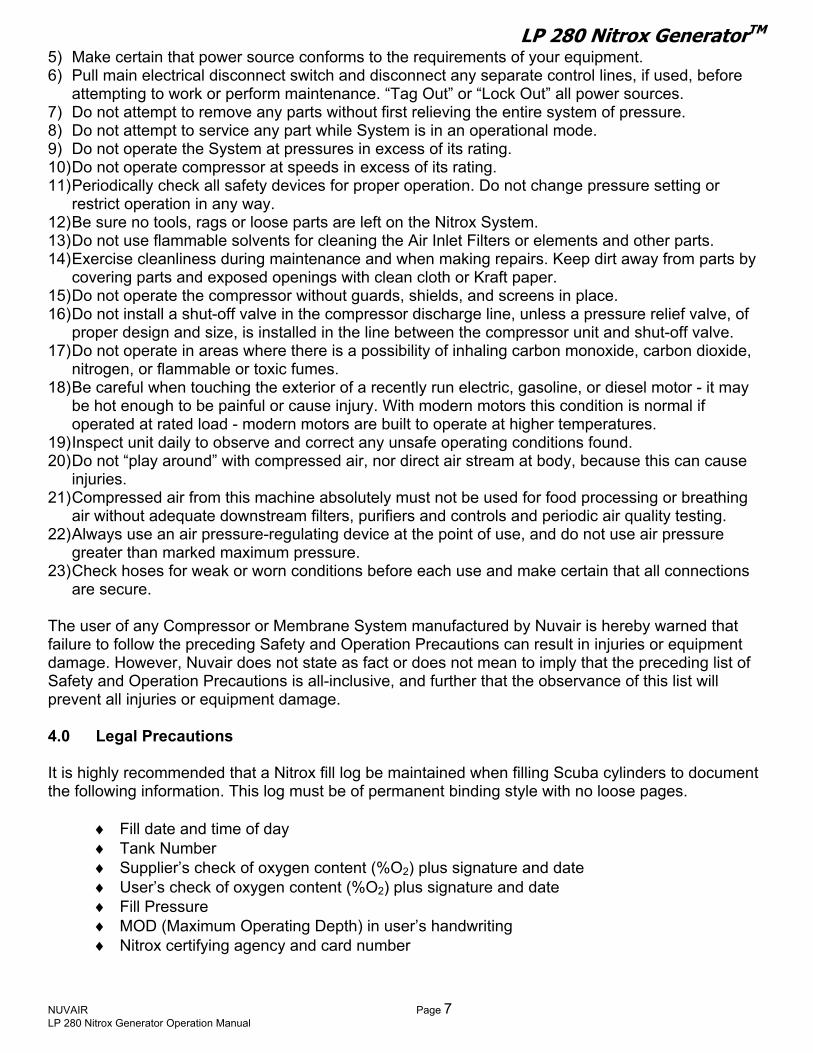
are secure. The user of any Compressor or Membrane System manufactured by Nuvair is hereby warned that failure to follow the preceding Safety and Operation Precautions can result in injuries or equipment damage. However, Nuvair does not state as fact or does not mean to imply that the preceding list of Safety and Operation Precautions is all-inclusive, and further that the observance of this list will prevent all injuries or equipment damage. 4.0 Legal Precautions It is highly recommended that a Nitrox fill log be maintained when filling Scuba cylinders to document the following information. This log must be of permanent binding style with no loose pages.
♦ Fill date and time of day ♦ Tank Number ♦ Supplier’s check of oxygen content (%O2) plus signature and date ♦ User’s check of oxygen content (%O2) plus signature and date ♦ Fill Pressure ♦ MOD (Maximum Operating Depth) in user’s handwriting ♦ Nitrox certifying agency and card number
NUVAIR Page 7 LP 280 Nitrox Generator Operation Manual

LP 280 Nitrox GeneratorTM
5.0 Theory of Operation The LP 280 Nitrox Generator TM is a turnkey package that produces oxygen-rich air (Nitrox) for delivery to the intake of a separate High Pressure (HP) Compressor. This HP Compressor then compresses the Nitrox to fill Scuba Cylinders or Storage Tanks. Although it is described as the “Nitrox Compressor”, it is also used to pump air. The Nitrox System allows for efficient and cost effective Nitrox production without the hazards or expense of blending with stored high-pressure oxygen (O2). Instead, the system uses a Semi-Permeable Membrane to produce Nitrox from air. A portion of the nitrogen in air is separated out, leaving an oxygen rich Nitrox mixture. This Nitrox mixture can be pumped up to a maximum pressure of 3600 P.S.I. (250 bar) when filling Scuba Cylinders or Storage Tank. The Nitrox System uses an LP Rotary Screw Compressor, Air Aftercooler, Refrigerated Air Dryer and Filtration to provide the Membrane System with a source of clean, pressurized air for separation. The air is filtered to CGA Grade D air quality prior to entering the Membrane System so it will not damage or plug the Membrane fibers. Specifications for Grade D air are provided in the Appendix. The LP280 Membrane System is rated for a maximum supply pressure of 300 P.S.I. (20 bar) and works well with the 190PSI (13 bar) maximum pressure from the Rotary Screw Compressor. An Input Back Pressure Regulator reduces these input pressures to appropriate levels for Nitrox production. The air is then heated to a temperature that provides stability over a wide range of ambient conditions, is optimal for membrane permeation and provides protection to the membrane from condensate. The heated air enters the Membrane, which is made up of thousands of miniature hollow fibers. The walls of these fibers are semi-permeable and designed for different gases to move through them (or permeate) at different speeds. The resulting gas mixture is known as the “permeate”. As air flows through the hollow fibers, both oxygen and nitrogen permeate through the fiber walls. The oxygen permeates faster than the nitrogen, which produces permeate with an oxygen content greater than air. The gas that reaches the end of the hollow fibers without permeating is almost entirely nitrogen and is discharged. The flow rate of this discharge is set by the factory via a fixed orifice, which controls the permeate to contain a constant 44% O2 under normal operating conditions. The permeate is a concentrated mixture that must be diluted with additional air prior to entering the Nitrox Compressor. It exits the Membrane at ambient to slightly negative pressure and travels into the Mixing Tube, where it mixes homogeneously with filtered outside air. The amount of dilution, and thus final %O2, is obtained by adjusting the Input Back Pressure Regulator. As input pressure is increased, permeate flow increases, air flow decreases, and a higher %O2 Nitrox is produced. As input pressure is decreased, permeate flow decreases, air flow increases, and a lower %O2 Nitrox is produced. This relationship between permeate flow and air flow exists because the total of these two flow rates will always equal the intake flow rate demanded by the Nitrox Compressor. The resulting Nitrox mixture is analyzed for %O2 before entering the Nitrox Compressor for approximate content and again when pumping Nitrox for precise content. A unique feature of Nuvair Nitrox Systems is that the input pressure that correlates to a specific Nitrox %O2 is repeatable. For example, if your Nitrox Compressor pumps 36% O2 when the input pressure is at 125 P.S.I. (9 bar), then adjusting the Regulator to 125 P.S.I. (9 bar) during the next use will produce the same mixture.
NUVAIR Page 8 LP 280 Nitrox Generator Operation Manual

LP 280 Nitrox GeneratorTM 6.0 Low Pressure Rotary Screw Compressor Technical Data Capacity and Power Consumption:
♦ Normal working pressure – 80-175 P.S.I. (5.5-12 bar) ♦ Capacity at normal working pressure – 32 cfm (920 l/min) ♦ Shaft power at normal working pressure – 10.2 hp (7.65 kW) ♦ Maximum working pressure – 190 P.S.I. (13 bar) ♦ Minimum working pressure – 44 P.S.I. (3 bar) ♦ Idling shaft power consumption – 2.3 hp (1.7 kW) ♦ Transmission – Belt drive
Cooling: ♦ Allowed ambient temperature – 32-104°F (0-40°C) ♦ Compressed air temperature above cooling medium temperature – 50°F (10°C) ♦ Cooling air flow – 635 cfm (0.3 m³/s) ♦ Maximum cooling air pressure drop – 0.12 in H2O (30 Pa) ♦ Cooling air temperature rise – 64°F (18°C) ♦ Oil cooler heat rejection – 324 BTU/min (5.7 kW) ♦ Aftercooler heat rejection – 40 BTU/min (0.7 kW)
Motor and Electrical Values:
♦ Motor - F class, IP55, 10hp (7.5 kW) ♦ Speed of rotation – 2920 rpm ♦ Fuse (max) – 25 A ♦ Compressor current – 16 A at 380 V / 50 Hz ♦ Control voltage – 230 V
General Technical Data: ♦ Oil Content – 3 mg/m3 ♦ Noise level (Cagi Pneurop) - 64dB ♦ Compressor weight – 473 lb (215 kg)
NUVAIR Page 9 LP 280 Nitrox Generator Operation Manual

LP 280 Nitrox GeneratorTM 7.0 System Components • Low Pressure Rotary Screw Compressor • Nuvair 546 TM Food Grade Rotary Screw Compressor Lubricant • Refrigerated Air Dryer or Volume Tank • On/Off Flow Valve (optional) • Input Back Pressure Regulator with Pressure Gauge:
♦ Pressure Input to Regulator 80-189 P.S.I. (5.5-13 bar) ♦ Output Pressure from Regulator 80-175 P.S.I. (5.5-12 bar) depending on HP Compressor size
and Nitrox %O2 • Low Pressure Filtration, Grade D Breathing Air, including three stages:
♦ Coalescing & Particle Removal to 1 micron, auto drain, differential pressure indicator ♦ Water & Oil Vapor Removal to 0.01 micron, auto drain, differential pressure indicator ♦ Oil Vapor Removal to 0.003 PPM, manual drain
• Heater including: ♦ Thermostat Control ♦ Digital Temperature Gauge ♦ Pressure Switch
• Semi-Permeable Membrane – compatible with HP Compressors rated up to 10 cfm (283 L/min) • Mixing Tube & Air Intake Filter • Nitrox Off Mixing Tube Rated 560 l/m@ 32%, 420 l/m @ 36% & 280 l/m @ 32% • Nuvair Pro O2 Remote TM Panel Mount Inline Oxygen Analyzer • Compressor Intake Hose for Nitrox Compressor • Nitrogen Discharge Hose (optional) • Nuvair Pro O2 TM Fill Oxygen Analyzer, including:
♦ High Pressure>Low Pressure Regulator ♦ Flow Restrictor, 1 - 5 L/min
• Nitrox Compressor Lubricant: ♦ Nuvair 455 TM Food Grade Lubricant (standard) ♦ Nuvair 751 TM Diester Based Lubricant (optional)
• Air/Nitrox Quality Analysis Kit NUVAIR Page 10 LP 280 Nitrox Generator Operation Manual

LP 280 Nitrox GeneratorTM
8.0 Nitrox System Specifications
Nuvair Nitrox Generator Model
LP 280 50 Hz
LP 280 60 Hz
Height 33.5 in (850 mm)
33.5 in (850 mm)
Width 36.6 in (930 mm)
36.6 in (930 mm)
Depth 33.0 in (838 mm)
33.0 in (838 mm) Ph
ysic
al
Spec
ifica
tions
Weight 715 lb (325 kg)
715 lb (325 kg)
Full
Load
A
mps
Total Requirement for LP Compressor
& Membrane Heater
21 A @ 380 VAC, 37 A @ 220 VAC,
50 Hz
37 A @ 220 VAC, 60 Hz
Operating Pressure Range
80-175 psi (6-11 bar)
80-175 psi (6-11 bar)
Maximum Input Pressure
300 psi (21 bar)
300 psi (21 bar)
Supply Air Volume Range
8-25.4 scfm (212-736 L/min)
8-25.4 scfm (212-736 L/min)
LP Supply Air Quality
Grade D Grade D
Mem
bran
e In
put
Optimum Temperature
110 +/- 5oF (43 +/- 3oC)
110 +/- 5oF (43 +/- 3oC)
Nitrox %O2 Range
24 - 40% 24 - 40%
Nitrox Compressor Recommendations
To Pump Nitrox up to 40%O2
To Pump Nitrox up to 36%O2
To Pump Nitrox up to 32%O2
Charging Rate 6-10 scfm (170-280 L/min)
6-14 scfm (170-400 L/min)
6-18 scfm (170-510 L/min)
Horsepower – Electric
5-7.5 hp (3.8-5.5 kW)
5-15 hp (3.8-7.5 kW)
5-20 hp (3.8-15 kW)
Horsepower – Gas
6.5-11 hp (4.9-8.3 kW)
6.5-18 hp (4.9-14 kW)
6.5-24 hp (4.9-16 kW) H
P N
itrox
C
ompr
esso
rs
Horsepower – Diesel
9-10 hp (6.8-7.5 kW)
9-18 hp (6.8-14 kW)
9-27 hp (6.8-20 kW)
NUVAIR Page 11 LP 280 Nitrox Generator Operation Manual
LP 280 Nitrox GeneratorTM
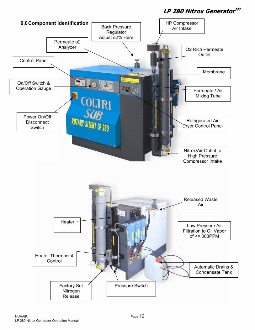
9.0 Component Identification
HP Compressor Air Intake
O2 Rich Permeate Outlet
Membrane
F
Refrigerated Air Dryer Control Panel
On/Off Switch & Operation Gauge
Control Panel
Permeate o2 Analyzer
Permeate / Air Mixing Tube
Heater
Heater Thermostat Control
Pressure Switch
Released Waste Air
NUVAIR Page 12 LP 280 Nitrox Generator Operation Manual
Low Pressure Air iltration to Oil Vapor
of <=.003PPM
Power On/Off Disconnect
Switch
Back Pressure Regulator
Adjust o2% Here
Automatic Drains & Condensate Tank
Factory Set Nitrogen Release
Nitrox/Air Outlet toHigh Pressure
Compressor Intake

LP 280 Nitrox GeneratorTM
NUVAIR Page 13 LP 280 Nitrox Generator Operation Manual
System Drawing / Schematic
LP 2
80 N
itrox
Gen
erat
orTM
Syst
em C
ompo
nent
s Sh
own
With
in D
ashe
d Li
nes

LP 280 Nitrox GeneratorTM 10.0 System Flow Chart
Refan
Thermostat Controlled Heater Heat 3ºC) s Air to 110ºF (4
Membrane Separates Supply Air Into Permeate and
Nitrogen Rich Gas
Permeate Exits Membrane Containing 44% O2
Mixing Tube MPermeate to C
Containing 24
ixesreate-40
Air & Nitrox
% O2
r Mo +/-
onitors 1% O2
er Air Intake Delivers Filtered Ambient Air to Mixing Tube
Inline O2 Analyzer Monitors Nitrox before
Compression to +/- 2% O2
HP Nitrox Compressor with Moisture Removal &
Filtration Compresses Nitrox
Fill O2 AnalyzeNitrox Mixture t
Optional Vacuum Pump or Blow
LP 280 Nitrox GeneratorTM
System Components Shown Within Dashed Lines
NUVAIR Page 14 LP 280 Nitrox Generator Operation Manual
LP Aftercooler RemovesMoisture
LP Air Compressor ProducesLP Supply Air
rigerated Dryer Removes d Collects Moisture and Delivers Supply Air
Optional Volume Tank
LP Supply On/Off Flow Valve Controls Supply Air
LP Air Filtration Produces Grade D Air
BP Regulator Adjusts Pressure and Desired
Nitrox O2%
Nitrogen Rich Gas Exits Through Fixed Orifice
HP Nitrox Delivered to Storage
HP Nitrox Delivered to Scuba Cylinde
- OR - r

LP 280 Nitrox GeneratorTM
12.0 Preparing Existing HP Compressors
me compressors are not suitable for compressing oxygen-rich air, i.e., nitrox. Use of an nsuitable compressor may lead to possible compressor damage and/or fires or explosion. h s can lead to serious personal injury or death. If there is any use of n x sting compressor, contact Nuvair or the compressor manufact connect y ur i rox System to your machinery.
12.1
h purification s r to which the Nitrox System will be installed must produce Grade E breathing air appropriate for diving use. This is the same standard applied to ll breathing air compressors. Please make sure you place extra cautio ment of
filters in the purification system to ensure these standards at all time r Grade E ir are provided in the Appendix.
ecent air quality test from your existing Compressor is highly recommended prior to installing the i ox System. After installation, te e Air/Nit t r vided. Quarterly testing is mandatory once the System is operational.
r athing air compressors must pro appropriatec ordance with the appropriate CGA Grade. Periodic air quality testing is mandatory to
assure compliance.
12.2 Replacement of Compressor Lubricant
For an existing Compressor to be used with the mbr f old Love rox Compressor Lubricant.
i ox Compressor Lubricant is compatible with both air n Nitrox.
) Start Compressor and run for 10 mCompressor Lubricant. Shut off Compressor, remove Lubricant, and replace Lubricant Filter if any.
) Refill e NuvaiCom lied. Do not overfill.
) After 10 hours, repeat Steps 1 and 2.
After running the compressor, the lubricant will be very hot. Take care when re
rain plug and draining the lubricant to avoid burns.
WARNING So
iit
e
e
rtro
ec
emtrd
uT doubt regarding the
urer before you ao
eN
Purification System
ystem on the existing HP Compresso T
a n on timely replaces. Specifications foth
a
AN st a Nitrox sample using th rox Quality Analysis Kip
B duce breathing air for diving use in a
M ane System, all traces od and replaced with Nit
ubricant must be reNa 1 inutes to warm
2 Compressor with thpressor Lubricant supp
r Air/Nitrox DNLu
FN
Lu )
3
d
NUVAIR Page 15 LP 280 Nitrox Generator Operation Manual
Nuvair™ 751 iester Based Air & itrox Compressor bricant (Optional)
Nuvair™ 455 ood Grade Air & itrox Compressor brica t n (Standard
CAUTION
CAUTION
moving the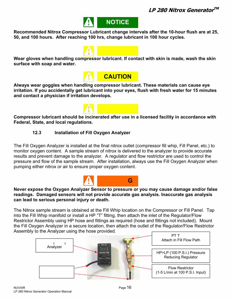
LP 280 Nitrox GeneratorTM
NUVAIR LP 280 Nitrox Generator Operation Manual
ecommended Nitrox Compres bri ervals after the 10-hour flush are at 25,
essor lubricant. If contact with skin is made, wash the skin urface with soap and water.
12.3 Installation o Oxy
mage to the analyzer.ressure and flow of the sample stream. Af
pumping nitro
serious personal injury or dea
intoRethe Fill Oxygen Analyzer in a secure location
sor Lu
NR cant change int50, and 100 hours. After reaching 100 hrs, change lubricant in 100 hour cycles.
Wear gloves when handling compr
CAUTION
s
Always wear goggles when handling comirritation. If you accidentally get lubricantand contact a physician if irritation devel
Compressor lubricant should be incineraFederal, State, and local regulations.
f Fill The Fill Oxygen Analyzer is installed at the fmonitor oxygen content. A sample stream oresults and prevent dap
either x or air to ensure proper Never expose the Oxygen Analyzer Sensreadings. Damaged sensors will not provcan lead to The Nitrox sample stream is obtained at the
the Fill Whip manifold or install a HP “T”strictor Assembly using HP hose and fittin
Assembly to the Analyzer using the hose pro
Pro O Fill O
LP Hose to
Analyzer
2 2Analyzer
OTICE
CAUTION
s pressor lubricant. These materials can cause eye into your eyes, flush with fresh water for 15 minuteops.
CAUTIONPage 16
e with
g
l, etc.) to te
A regulator and flow restrictor are used to control the ter installation, always use the Fill Oxygen Analyzer when
or you may cause damage and/or false e gas analysis. Inaccurate gas analysis
th.
ocation on the Compressor or Fill Panel. Tap , then attach the inlet of the Regulator/Flow
quired (ho s not included). Mount , then attach the ulat
d.
ted after use in a licensed facility in accordanc
en Analyzer
inal nitrox outlet (compressor fill whip, Fill Panef nitrox is delivered to the analyzer to provide accura
oxygen content.
or to pressureide accurat
WARNIN
Fill Whip l fittinggs as re se and fitting
outlet of the Reg
¼” N
or/Flow Restrictor
ee Fitting – vide
PT TAttach in Fill Flow Path
HP>LP (100 P.S.I.) Pressure Reducing Regulator
Flow Restrictor (1-5 L/min at 100 P.S.I. Input)
G
LP 280 Nitrox GeneratorTM
13.0 Installing the Nitrox System
any information in this manual conflicts with any of the other manuals call Nuvair before proceeding.
ould neverystem. Operation at higher temperature
damaged membrane will not pro theersonal injury if the gas is used for divin
) Unpack the system and remove from thehas been no damage during sh . IfPlease take photos and supply detailed i
eleexceed 100oF (38oC).
4) The H Ther) A 13 foot corrugated Compressor Intake
) Not Applicable for this model.
NOTICE If
Ambient room temperature sh
Sduce
p
13.1 Precautions 1) Please read all information supplied befo2
ipping
3) Place the system in a permanent locationspacing of 18” from adjacent walls. S
eater mostat has been set in t5
the HP Compressor intake. If a longer hoContact Nuvair for assistance.
13.2 Attaching the Air Supp 1
NUVAIR LP 280 Nitrox Generator Operation Manual
CAUTION
exceed 100oF (38oC) during operation of the Nitrox s may lead to system damage and malfunction. A mixture which can lead to severethout proper analysis.
ysically installing the Nitrox System. pallet. Visually inspect the system to make sure there e call Nuvair to file a damage report. nformation about the damage.
ct a location where ambient room temperature will never
ot adjust. Hose has been provided to connect the Nitrox System to
correct nitrox g purposes wi
re ph
damaged, pleas
near the existing HP Compressor. Allow a minimum
he factory. Do n
se is required, the diameter must also be increased.
ly
Page 17

LP 280 Nitrox GeneratorTM
13.3 `Attaching Compressor Intake Hose
is will increase the amount of suction the compressor must generate which can
ause overheating and damage com aged compressors can pump purities into the diver’s breat as. e serious injury or death.
) Attach the other end of the Intake Hose to the intake of the Nitrox Compressor and secure with the hose cl
13.4 Attachin
he nitrogen discharge from tystem and LP Compressor.
stalled in a closed building, the outside. An optional Nse of a Nitrogen Discharge H
Do not substitute a compressor intake hose of a smaller diameter or longer length than thatsupplied. Thc pressor. Dam
This may causto the
hing gim
1) Cut the Intake Hose to proper length to reach between the Nitrox System and HP Compressor. Reattach end fittings
2) Attach the Intake Hose to the Nitrox System outlet. 3
amp provided.
Attach This End of Hose to Nitrox System Outlet
TSventilated room that meets inintou
ure nitrogen is a colorlessixtures containing more t
unconsciousness and may The nitrogen discharge fromopen air with good circulatiMembrane System or LP coserious personal injury or dspace, anyone entering thisimmediately resuscitated.
Pm
WARNING
NUVAIR LP 280 Nitrox Generator Operation Manual
Attachto Co
this End of Hosempressor Intake
g Nitrogen Discharge H
he Membrane must be is This requirement will be
y standards for Comboat, or similar enclosed itrogen Discharge Hose m
ose, please contact Nuv
dustr
, odorless, tasteless gahan 84% nitrogen at surcause death.
the Membrane shouldon. Failure to isolate thmpressor could lead toeath. If you allow this p space will quickly lose
WARNI
Pag
Secure Hose to Nitrox Compressor intake with HoseClamp as shown on this Coltri HP Compressor.
CompressorIntake Hose
ose (Optional)
olated from the air intakes of the Membrane met if the Nitrox System is installed in a well-pressor installations. If the Nitrox System is space, the nitrogen discharge must be vented ay be needed. If your installation requires the
air for assistance.
DANGER s that will not support life. Breathing gas face pressures will lead tobe vented to a well-ventilated room or to e discharge from the air intake of the incorrect nitrox mixtures, resulting in ure nitrogen to accumulate in an enclosed consciousness and will die if not
NG
e 18

LP 280 Nitrox GeneratorTM
NUVAIR Page 19 LP 280 Nitrox Generator Operation Manual
he LP Compressor maximum pressure has been ctory set to pump up to 190 P.S.I. (13 bar) and en go idle until the pressure drops down to a low re roximately 165 P.S.I. (11 bar). hi own as the compressor differential ressure.
his output setting allows the system to be used with a P Compressor having a rated capacity up to 10 cfm 83 l/m) and produce 40%.
ualified electrician. proper wiring may lead to fires, which can cause serious personal injury or death.
rior to making the electrical powe ectio stem specifications provided in this
Factory Set Thermostat Control
200 PSI (13.5 Bar) Over Pressure Relief
Hose Connection for Nitrox Compressor
Nitrogen Discharge to Negative Pressure Nitrox Outlet Ambient
Inline O2 Sensor
Fixed Factory Set
13.5 Output Pressure Adjustments
Tfathp ssure of app
s cycle is knTp TH(2
13.6 Electrical Power Connection
Never use extension cords to provide power to your Nitrox System. The system must be properly wired according to national and local electrical codes by a q
WARNING
Im P n, check all syr connmanual. When working on the Nitrox System the main breaker at the power source must be “lockedout” in the Off position.
LP 280 Nitrox GeneratorTM Amper emage Load for Syst
Approximately 37 A for 220 V three phase service Approximately 21 A for 380 V three phase service
P Co Check
♦♦ L mpressor Rotation
lwaysA turn on (bump) starter and run motor very briefly to check r proper direction of rotation (see arrow above pulley). roper e exhaust air out the top and raise the st pa
foP Rotation will forc
per. te
CAUTION Operation in reverse direction for even a short period of time will damage a Rotary Screw Compressor. The Cabinet Power Switch must be in the Off position to remove the front panel of the Compressor. This Switch terminates power to the Compressor answitch in the
d electrical panel. Store the compressor with this Off position. When working on the Compressor the main breaker at the power source
ust also be “locked out” in the Off position. The Nitrox System has circuit breaker protection for the ocated behind the front panel.
13.7
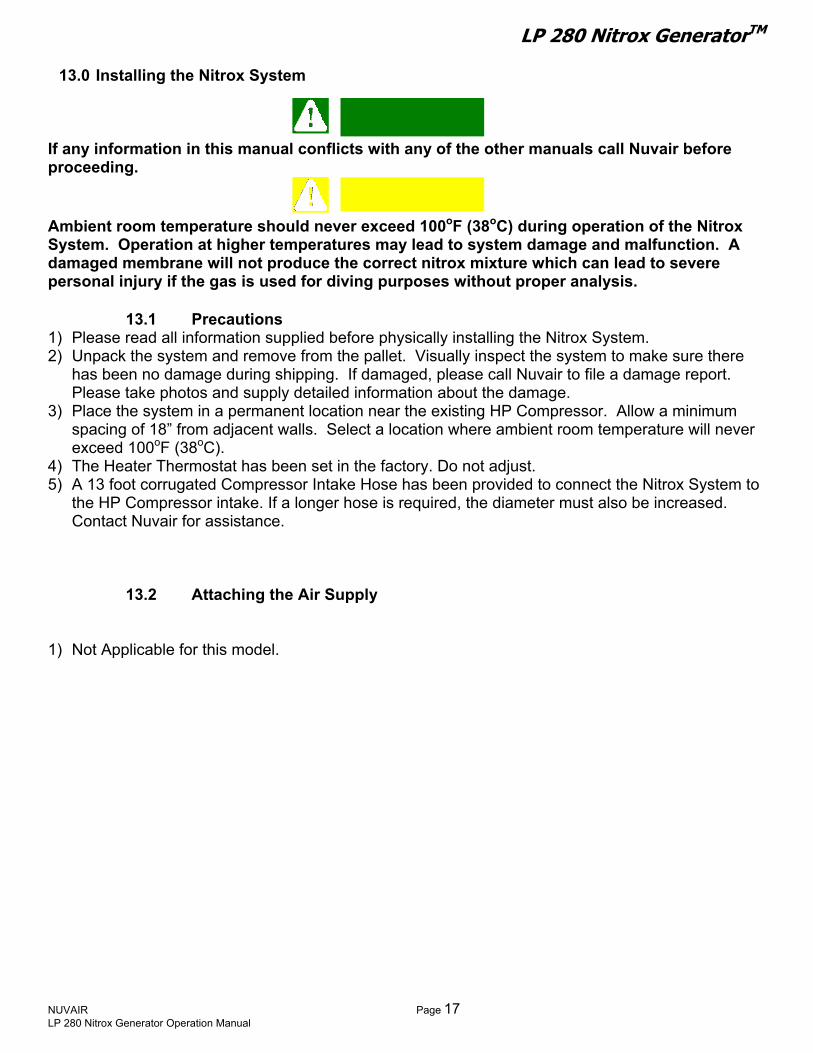
Before using your Nitrox System to pump nitrox, test a sample of the nitrox roduced using the Air/Nitrox Qua alys verify compliance with
mCompressor Motor and Membrane System Heater l
Air/Nitrox Quality Testing
p is Kit provided tolity AnCGA standards. Quarterly testing is mandatory once the System is operational. Air/Nitrox Quality
Analysis Kit
NUVAIR Page 20 LP 280 Nitrox Generator Operation Manual

LP 280 Nitrox GeneratorTM
14.0 Pre-Operation Instructions
o not allow nitrox to be discharged into the air storage system. Nitrox introduced into the air diver to suffer from oxygen poisoning at depth. Oxygen
o not allow air to be discharged into the Nitrox storage system. Air introduced into the nitrox storage system could cause a diver to suffer from decompression sickness if the nitrox mixture is not analyzed properly and is u nt
Compressor Lubricant Levels
14.2 Membrane System Regulator and Flow Valve
A Back Pressure Regulator is used to reduce supply pressure to the
) Reduce input pressure setting by turning the Regulator adjustment knob counter-clockwise (CCW) a few rotations.
) Make sure the (optional) LP Supply Air On/Off Flow Valve is in the Off position if supplied.
WARNI
Dstorage system could cause a poisoning is extremely dangerous and can lead to drowning.
WARNING
NG
D
sed underwater under the assumption it is a differemix.
14.1
Check lubricant levels before starting the LP and HP Compressors, and add lubricant as required. Use only the lubricants specified.
ee compressor manual for oil level check. S
Membrane System to a typical range of 80 – 175 P.S.I. (5.5-12 bar) An On/Off Flow Valve is used to control the flow of LP supply air into the Membrane System. Prepare the Membrane System as follows: 1
A
2
NUVAIR Page 21 LP 280 Nitrox Generator Operation Manual
BP Regulator obdjustment Kn
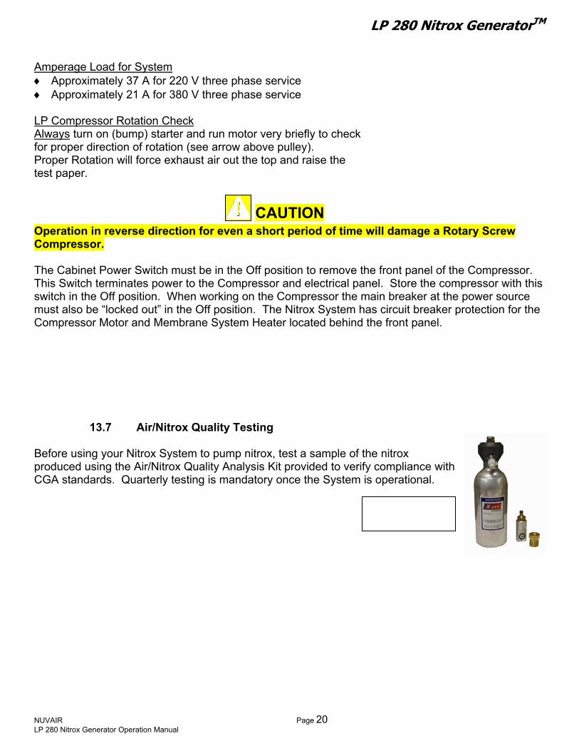
LP 280 Nitrox GeneratorTM 14.3 Oxygen Analyzer Calibration
as production may be monitored he Inline Oxygen Analyzer before entering the Nitrox
Compressor to obtain a rough esti of % ever, do not rely on this reading as an dication of %O2 at the Nitrox Compressor outlet. Prior to pumping nitrox into a Scuba cylinder or
G with tmate O2 (+/- 2%); how
inSurface Supply System, it must be monitored with the Fill Oxygen Analyzer to obtain a precise measurement of %O2 (+/- 1%). Both Oxygen Analyzers must be calibrated prior to each use.
P
ore each use. See Oxygenorrect calibration procedures. Improper calibration of the Fill Oxyge use of incorrect nitrox mixtures, which may cause serious injury
sing the gas mixture.
At altitude ve en Analyzer may not be achievable. See Fill Oxygen Analyzer manual f
gejury
en readings that can vahum ced in the nitrox flow and tuse he Fill Oxygen Analyzer supplies
fill alyzer.
alibrate Oxygen Analyzers as follows:
) Close Membrane System On/Off Flow Valve 2) Slightly open fill whip valve on HP Nitrox Compre
desired, insert clean rag in yoke to act as sound muffler. 3) Turn on HP Nitrox Compressor according to manufacture4) Adjust fill whip valve so the running Compressor maintains 1500-
will now be flowing past both Oxygen Analyzers for calibration purpos
Oxygen Analyzers must be calibrated befcthu
s abo sea level, a correction factor must be used wh
readings at various altitudes. Improper calibration of the Fill Oxythe use of incorrect nitrox mixtures, which may cause serious inusing the gas mixture.
WARNING
WARNING
WARNING
The Inline Oxygen Analyzer supplies oxyg
idity, and pressure changes experiend for rough estimates of %O . T
ry
2readings, within +/- 1% O2. For Scuba cylinder nitrox
with a third independent Oxygen An fills, the user m
ssor to relieve any re
r’s instructio2000
C 1
NUVAIR Page 22 LP 280 Nitrox Generator Operation Manual
Inline Oxygen AnalyzerProvides Rough Reading
Frovides Precise Reading
ill Oxygen Analyzer
Calibration Knob
Analyzer manuals for en Analyzer may result in or death to the diver
calibrating the Fill Oxygen or correcting analyzer n Analyzer may result in or death to the diver
e to heat, herefore should only be more accurate oxygen
the final
es.
+/- 2% O2 du
ust always verify
sidual pressure, and then, if
ns. P.S.I. outlet pressure. Air

LP 280 Nitrox GeneratorTM
NUVAIR Page 23 LP 280 Nitrox Generator Operation Manual
5) Monitor all gauges for proper operating range and check all connections for
leaks. 6) Calibrate Oxygen Analyzers while the Nitrox Compressor is
Optional Sound Muffler for HP Nitr
pumping air. Refer to the Oxygen Analyzer manual included Note that special calibration
proceduressea level.
♦ er - Calibrate Analyzer so Display
♦ Fill Ox lay reads ade E breathing air present at
the Sensor. Different settings may be used depending on location, so verify your actual ambient conditions and refer to the Oxygen Analyzer manual for details.
with the Nitrox System for details. may be required when operating at altitudes above
Inline Oxygen Analyzreads 20.9%.
ygen Analyzer - Calibrate Analyzer so Disp20.9% to correlate with the Gr
Fill Oxygen Analyzer - Alternate Calibration Method The Fill Oxygen Analyzer can also be calibrated in ambient air as an alternative. This is especially useful during routine re-calibration
hile the system is operaw ting. Different settings may be used epending on location, so verify your actual ambient conditions and fer to the Oxygen Analyzer man det
pter Cap to the Analyzer. 5) The Fill Oxygen Analyzer is no y fo
er at this point. The second whi be used to control HP compressor outlet pressure.
ttach one HP compressor Fill Whip to a Scuba Cylinder.
Add
dre ails. ual for 1) Remove the Flow Adapter Cap covering the Sensor. 2) Expose the Sensor to ambient air for approximately 15 seconds. 3) Adjust Calibration Knob until Display reading stabilizes at 20.9%. 4) Reinstall the Flow Ada
r use. w read
14.4 Attaching Scuba Cylinder
Only one fill whip is attached to a Scuba Cylind
NOTICE
to ALeave Cylinder Valve closed.
itional cylinders or storage tanks can be attached after the system is ready to pump Nitrox.
Insert Cin Fill W
Adjust FiValve to Maintain
Pressure
ll Whip
ox Compressor
lean Rag hip Yoke
Sensor CapRemovedp wil
CalibrationKnob
l continue
Fill Whip Attached to Scuba Cylinder

LP 280 Nitrox GeneratorTM 15.0 Producing Nitrox
ll exposbot nd high-pressure gas. Gas, even under moderate pressures, can cause extreme
ny part of your body.
1) Oxygen Analyzer calibration is complete. ) Turn on your HP Compressor. Allow outlet pressure to build up
ted
The equipment you will be using to manufacture nitrox (oxygen rich air) wi
h low ae you to
bodily harm. Never allow any gas stream to be directed at a
15.1 Flow to Membrane
Verify that 2
to approximately 2300 P.S.I., then crack open the unconnecfill whip to maintain 1500-2300 P.S.I.
3) 4) Tur5) Tur f
sup6) Adj to a
Heater Pressure Switch. Increase pressure by slowly turning the Regulator Knob CW or decrease pressure by turning the
) Verify that Heater Thermostat Control green indicator light is on.
een
be required.
roduce the correct nitrox mixture w
eached.
Verify that Inline Oxygen Analyzer reads 20.9%. n on LP Compressor and refrigerated dryer. n on Membrane System by slowly opening the Flow Valve iplied. ust input pressure to approximately 100 P.S.I ctivate
Knob CCW. 7
The light will remain on until operating temperature is reached and will then cycle on and off. When light turns off, check Heater Temperature Gauge to verify air temperature is betw105-120 ºF (40-49 ºC). Temperature is preset at the factory and changes to the Thermostat Control should not
Heater
Temperature
Gauge
The On/Off Flow Valve on the Membgas can damage the Membrane and pfor diving purposes without proper a The Heater Thermostat Control gre
WARNING
re
NUVAIR LP 280 Nitrox Generator Operation Manual
Heater ThermostatControl
hich
n ind
rane othe
naly
CAUTION
onents. A damaged membrane will not can lead to severe personal injur
icator light w
System must be opened slowly. A sudden rush of r system comp
y if the gas is used
on until operating temperature is
sis.
NOTICE ill stay
Page 24

LP 280 Nitrox GeneratorTM
o not change the temperature g on
su
hig%O
settinD
Changes in temperature settings may caunot produce the correct nitrox mixture whused for diving purposes without proper
15.2 Setting Proper Pres
The input pressure to the Membrane Systemof the Nitrox mixture produced. As input pre
her %O2 Nitrox is pumped. As pressure 2 Nitrox is pumped.
1) Increase input pressure by slowly turning
As the pressure rises, watch t
2)
3) pressure and temperature
CW while monitoring the Pressure GaugAnalyzer. increase in the Analyzer %O2 reading. Increase or decrease pressure slowly unAnalyzer displays the %O2 desired in theAllow system(approximately 5-8 minutes). ♦ Regulated Membrane System press
80– 175 P.S.I (5.5-12 bar), dependinproduced.
♦ Heater temperature range should be
15.3 Final Adjustments Bef
) As the Nitrox initially makes its way throu
adjustments to the Membrane System inobtain the exact Nitrox %O2 de as inAnalyzer.
1Compressor, the %O2 reading on the Fillincrease to read approximately the sameAnalyzer. This should happen within 3-5
2) When the two Analyzers read within +/- 1
sired
3) The system is now ready to pump Nitrox
NUVAIR LP 280 Nitrox Generator Operation Manual
CAUTION
the Thermostat Control without contacting Nuvair.re
the %O2
se Membrane damage. A damaged membrane willich can lead to severe personal injury if the gas is
analysis.
determinesssure is increased, a is decreased, a lower
the Regulator knob
he corresponding
to stabilize
eing
es and Inline Oxygen
til the Inline Oxygen final Nitrox mixture.
ure range should be g on Nitrox %O2 b
105-120 ºF (40-49 ºC).
ore Pumping Nitrox
gh the running Nitrox
ake any final put pressure necessary to d Fill Oxygen
Inline Oxygen Analyzer
NOTICE
Oxygen Analyzer will slowly %O2 as the Inline Oxygen minutes. %, m
icated on the
. Fill Oxygen Analyzer
Page 25

LP 280 Nitrox GeneratorTM
15.4 Pumping
n nent disability or death.
+/- 2% O2 due to heat, humidity, sed for rough estimates of %O2. /- 1% O2. For Scuba cylinder
st always verify the fill with a third independent O2 analyzer.
Do more than 40% oxygen. Pu ygen may lead to fires or
.
Do ssor rating, and never above 3600 P.S 00 P.S.I. (250 bar). Higher pressu sonal injury or death.
o oxygen cleaning of standard cylinders or plumbing is mandatory when using the Nitrox ystem to produce nitrox containing a maximum of 40% oxygen. When filling oxygen clean ylinders, hyper-purification of the nitrox is required using an optional Oxygen Compatible Air urification system available from Nuvair.
his Nitrox System does not prod itr
Never fill a cylinder that is marked, “For O
brefille
Oncertification. Improper use of nitrox can b
This system is not cleaned for oxygen semixtures containing greater than 40% oxy40% oxygen will lead to explosions which
Nitrox
The use of enriched air nitrox does not eliminate the risk of decompression sickness (DCS) idiving. Decompression sickness can lead to perma
WARNING
The Inline O2 Analyzer supplies oxygen readings that can varyand pressure changes in the nitrox flow and should only be uThe Fill O2 Analyzer supplies more accurate readings, within +nitrox fills, the user mu
W
not use this system to produce nitrox mixtures containingmping nitrox mixtures with higher concentrations of ox
WARNING
explosions, which can cause serious personal injury or death
WARNIN not pump nitrox mixtures at pressures above the compre.I. (250 bar). The system is not rated for pressures above 36
res may lead to explosions which may cause serious per
NScp T uce n
by anything other than 100% oxygen cleaathing gas containing hydrocarbons cd with gas mixtures containing gas m
ly provide Scuba cylinder nitrox fills to
G
NOTICE
ARNING
NUVAIR LP 280 Nitrox Generator Operation Manual
DANGER
ox ceptable for 100% oxygen service. mixtures ac DANGER xygen Service,” with nitrox that has been producedoxygen clean cylinder with cylinder is subsequently
than 40% oxygen.
of of nitrox training and e fatal.
n system. Filling an an lead to explosions if theixtures containing greater
customers who have pro
WARNING
DANGER rvice and not all components are compatible with gas gen. Pumping gas mixtures containing greater than may cause severe personal injury or death.Page 26

LP 280 Nitrox GeneratorTM
NUVAIR Page 27 LP 280 Nitrox Generator Operation Manual
C o m p re s s o r G a u g e s A c c o r tu re rs re c o m m e n d a tio n s
H e a te r T e m p e ra tu re 1 0 5 -1
F ill O x y g e n A n a ly z e rs
N itro x S to ra g e P re s s u re D O N o f ta n k o r 3 6 0 0 P S I (2 5 0 B a r)
G A U G E R E C O M M E N D E D S E T T IN G
d in g to m a n u fa c
2 0 o F (4 0 -4 9 o C )
C a b in e t T e m p e ra tu re L e s s th a n 1 0 0 o F (3 8 °C )
C o m p re s s o r O u tle t P re s s u re 0 -1 9 0 P S I (1 3 b a r)
R e g u la te d P re s s u re to M e m b ra n e 8 0 – 1 7 5 P S I (6 -1 1 b a r) d e p e n d in g o n N itro x O 2 % .
S h o w in g th e p ro p e r re a d in g fo r in te n d e d f ill
O T e x c e e d ra t in g
Each Scuba cylinder belonging usto nalyzed by that customer at the nitrox
lling facility, using an oxygen er independent of those used with the Nitrox System.
he fill log. The me of day must also be included with the date, since some customers may fill the same ylinder more than once a day.
e
2) With fill whip bleed valve open an itrox hat Fill Oxygen Analyzer %O2 reading equals the desired Nitrox %O2
roper
drains if equipped. c)
to umidity and temperature chan ects o r. To recalibrate, turn off the embrane System On/Off Flow and ation instructions.
es and dumps condensate, the Fill Oxygen nalyzer reading will decrease momentarily due to the pressure drop in the system. It will turn to its previous reading wi econds after the auto drain sequence stops.
WARNING to a c
analyzmer must be a
fiAn employee must witness that the customer has properly analyzed the gas in each cylinder, noted the maximum operating depth for that mixture, and signed and dated ttic Fill Scuba Cylinders or HP Storage tanks as follows: 1) When filling a Nitrox Scuba cylinder, follow all industry standards. Do not exceed rated pressur
of cylinder, and do not exceed 3600 P.S.I. under any condition. flowing, verify td N
. 3) Close bleed valve, open cylinder valve, and fill cylinder. While filling, monitor system for p
operation: a) Monitor Oxygen Analyzers and recalibrate as required b) Manually drain all Compressor condensate periodically or listen for proper operation of auto-
Monitor all system gauges as shown in the table below. The Oxygen Analyzers may require re-calibration after 10-20 minutes of operation due
NOTICE
h n the Sensofollow calibr
ge effValve M
When the HP compressor auto drain engag
NOTICE
Are thin s
4) After filling is complete, close cylinder valve, vent the bleed valve, and remove the cylinder.

LP 280 Nitrox GeneratorTM
NUVAIR Page 28 LP 280 Nitrox Generator Operation Manual
) Test the nitrox %O2 in the cylinder using an independent Oxygen Analyzer such as the Nuvair O2
T . Calibrate analyzer
♦ Tank Number signature and date
♦ User’s check of oxygen content (%O ) plus signature and date
2 P.S.I. (250 bar) under any condition.
o Nitrox will be supplied to the HP Compressor, and it will pump ir only until the LP compressor is turned on. Both the Inline
5
MQuickstickbefore use in accordance with manufacturer’s instructions.
6) Repeat steps 1-5 until you have filled all Scuba cylinders. 7) Mark each tank with fill date, %O2, fill pressure, and MOD
(Maximum Operating Depth). 8) Log every Nitrox fill to document the following information:
♦ Fill date and time of day
♦ Supplier’s check of oxygen content (%O2) plus2
♦ Fill Pressure ♦ MOD (Maximum Operating Depth) in user’s handwriting ♦ Nitrox certifying agency and card number
♦ When filling a HP Nitrox storage tank, verify that Fill Oxygen Analyzer %O2 reading equals the desired nitrox %O . Open applicable line valves and tank valve, and fill with nitrox. Do not exceed rated pressure of cylinder, and do not exceed 3600After filling is complete, close all valves and turn off compressor or relieve pressure.
15.5 Pumping Air NaOxygen Analyzer and Fill Oxygen Analyzer should read 20.9% when the HP Compressor is pumping air.
lways use Oxygen Analyzers to itor o nt of
15.6 Shutting Down
1) Shut off the Membrane System by turning the Regulator adjustment knob CCW to reduce input pressure to minimum setting and then closing the (optional) On/Off Flow Valve.
2) Manually drain all filter, Compressor, and Volume Tank condensate drains. 3) Turn off LP Compressor On/Off Switch. The Compressor will go into shut down mode. 4) Turn off HP Compressor when it has returned to pumping air, as determined by a Fill Oxygen
Analyzer reading close to 20.9% O2.
Use Independent Oxygen Analyzer for Verification
NOTICE A xygen conte monany gas flowing through the System. Both air and Nitrox are subject to variations in oxygen content.
LP 280 Nitrox GeneratorTM
16.0 Nitrox Operation Notes
16.1 Correlation of Input Pressure to Oxygen
Content
ill noalways match specific input pressures once the System has warmed up. These pressures will be
O2P.S ( re or make a mark on the inputDo at you normally make, making sure System has warmed up first. The next tim i ) anAna ery clos g only minor adjustments of the regulator to achieve the exact desired %O2.
usi ts of the
16.2 Hot Fills
hile in the process of filling HP Nitrox Storage Tanks, you may have a need to supply a walk-in n change mixes as follows:
e the HP Nitrox Storage Tanks from ate valves.
) Record the Membrane System input pressure reading ) Slightly open fill whip valve on the HP compressor, and adjust so the running compressor
maintains 1500-2000 P.S.I. (100-140 bar) outlet pressure. the desired nitrox %O2 for the
stabilize, make any minor adjustments necessary to achieve the desired %O , and then fill cylinder in normal manner.
6) When f ous setting, and allow the Fill Oxygen Analyzer reading to stabilize. Make any minor adjustments necessary to achieve the desired %O , and then resume
After the 10 hour break-in period for your Nitrox System, you w tice that specific nitrox %O2’s
when the input pressure is at 125 pressure gauge indicating the %O2.
repeatable. If you find that the Fill Oxygen Analyzer reads 36%.I. 9 bar), record this pressu
this for each %O2 the n trox with 36% O2 is needed, adjust the regulator to 125 P.S.I. (9 bar d wait for the Oxygen
e to 36% O2, requirinlyzer reading to stabilize. You will find the analyzer reading to be v
NOTICE Use the Fill Oxygen Analyzer to verify the nitrox oxygen percentage prior to pumping. When
ng the input pressure reading to obtain specific oxygen percentage, minor adjustmen input pressure regulator may be required to obtain the exact percentage desired.
Wcustomer with a Scuba Cylinder fill of a different nitrox mix. You ca 1) With the Nitrox System and HP compressor operating, isolat
the HP compressor by closing appropri23
4) Adjust the input BP Regulator to the pressure corresponding toScuba Cylinder fill.
5) Allow the Fill Oxygen Analyzer reading to2
inished return regulator to previ2
filling Storage Tanks.
NUVAIR Page 29 LP 280 Nitrox Generator Operation Manual

LP 280 Nitrox GeneratorTM
17.0 Maintenance The follo st of uide. Refer to LP and HP Compressor manuals for complete maintenance requirements.
add proper Lubricants as required. See Compressor manuals for details.
conde
Us
can
system is located in an area where ther
Filtration Elements may be as little as 35%manual and Appendix for details on Filte 1) LP Compressor Lubricant: Change Rota
the first 50 hour break in period and everuse with Rotary Screw Compressors, suSee Section 15.3 and LP Compressor m
2) LP Filtration Inspection: On a weekly baand each Element for any unusual degra
3) LP Filtration Elements: Change LP Filtestandards. Visual differential pressure (Dmonitoring replacement intervals. See S
wing li daily and routine maintenance items is intended as a g
17.1 Daily Maintenance
Be sure to check compressor lubricant lethe proper lubricant level will lead to sys 1) Check Lubricant levels of both LP and H
2) Check HP Compressor Filtration for condoperation of condensate drains. Refer tomanual for details.
) Check LP Filtration for condensate and p3nsate drains.
17.2 Routine Maintenance
e only the specified Nuvair Lubricantspresents a risk of fire and/or explosion, asevere personal injury and death.
Be sure that all pressure has been relieve
ister. Failure to vent pressure from thserious personal injury or death.
If
NUVAIR LP 280 Nitrox Generator Operation Manual
CAUTION
Section 17.3 and
stem. The use of incompatible lubricants t in system damage. This can lead to
g the canister can lead to
vel prior to each day of operation. Failure to ensuretem damage.
P Compressors and
ensate and proper HP Compressor
roper operation of
in this sy
WARNING
nd may resul
WARNING d from the system prior to opening any filtration
e system prior to openin
CAUTION e is high humidity and high heat, the life of allof rated operating capacity. Check the compressor r Element Life Factors.
ry Screw Compressor Lubricant and Lubricant Filter after y 1500 hours thereafter. Only use Lubricants rated for ch as Nuvair 546 TM. Never mix Compressor Lubricants. anual for details. sis, inspect each Filter Bowl for the presence of moisture dation or wetness. See Section 15.4 for details. r Elements every 200 hours to maintain CGA Grade D air P) indicators on the HF7 and HF5 filters assist with
ection 15.4 for details. If the Nitrox System is operated in
Page 30

LP 280 Nitrox GeneratorTM high humidity and/or high temperature, Filter Elements must be changed more often. See
s on Filter Element Life Factors. ) Semi-Permeable Membrane: No maintenance required. Service life exceeds 20 years if LP
ery 3 months for visible particles. Change every 12 months or sooner if particles are visible.
6) Oxygen Analyzers: Replace Oxygen Sensor and Battery as required. See manual included with Nitrox System.
xygen Sensor or the Sensor itself. he Potassium Hydroxide chemical contained in the Sensor can cause severe injury or death.
ion immediately.
at your fingers or other parts of you iately flush affected area with clean,
sensation is an indication of a ned in the Sensor can cause severe
ju immediate medical attention if eye contact is made or skin stinging ersists.
The follo rox System, but proper maintenance is required to ssure opt um performance.
as ix Compressor Lubricants. Refer to HP Compressor manual for
details. ) Breathing Air Filters: Change HP Compressor Filter Elements in accordance with manufacturer’s
guidelines to maintain CGA Grade E breathing air standards.
Appendix for detail4
Filtration is properly serviced to maintain Grade D standards. 5) Membrane System Air Intake Filter: Inspect filter element ev
Do not swallow (ingest) either the electrolyte from the OTIf electrolyte or the Sensor is swallowed, seek medical attent
If after handling the Oxygen Analyzer or Sensor, you find th
r body feel “slippery” or the skin or eyes sting, immed
DANGER
DANGER
fresh water for at least 15 minutes. The stinging or slipperyleaking Sensor. The Potassium Hydroxide chemical contai
ry or death. Seek inp
wi g items are not integral parts of the Nitnima
1) HP Compressor Lubricant: Change HP Compressor Lubricant every 100 hours of operation in
accordance with manufacturer’s guidelines. Only use Lubricants rated for use with Nitrox, such Nuvair 455 TM or 751 TM. Never m
2
3) Air/Nitrox Quality Analysis: Take breathing air/Nitrox samples quarterly for analysis to assure compliance with CGA Grade E breathing air standards.
NUVAIR Page 31 LP 280 Nitrox Generator Operation Manual
LP 280 Nitrox GeneratorTM
The vair 546 TM Food Grade Synthetic
rec ther Compressor Lubricants.
Access to the oil filter, oil/air separator and oil drains is rough the front cabinet door.
17.3 Compressor Lubricant
LP Rotary Screw Compressor in your Nitrox System uses NuRotary Screw Compressor Lubricant. This lubricant is thinner than the lubricants that are used in
iprocating HP Compressors and should not be mixed with o
th
NUVAIR Page 32 LP 280 Nitrox Generator Operation Manual

LP 280 Nitrox GeneratorTM 17.4 LP Filtration
. proper sequence can cause damage to downstream components
pply air is critical to revent the passing of any residual oil vapor into the embrane System. Three stages of Hankison LP
ltration are used to produce Grade D air:
1) Particle Removal to 1 micron 2) Coalescing & Water/Oil Vapor Removal to 0.01
micron 3) Oil Vapor Removal to 0.003 PPM
iltration Inspection
Special attention needs to be given to the arrangement of the four LP Supply Air Filtration Elements and Bowls. Properly reinstall each Element and Bowl to the correct HousingIm The use of Grade D or better supMfi
F
pen each Filter and inspect as follows: . Inspect Bowl for the presence of moisture. A high
level of moisture build-up in the HF7 or HF5 Filter indicates improper operation of auto-drain floats. Any evidence of moisture in the HF1 Filter indicates the air is not cooling properly and moisture is not properly being removed. Excess moisture will prevent the final filter from operating properly.
. Inspect Elements for any unusual degradation or wetness. Element degradation can indicate more serious problems. Contact Nuvair for assistance,
hanging Filtration Elements
O1
2
C
hange Filter Elements every 200 hours. If the Nitrox ystem is operated in high humidity and/or high mperature, Filter Elements must be changed more often. ee Appendix for details on Filter Element Life Factors.
Visual DP indicators on the HF7 and HF5 filters assist with monitoring replacement intervals. 1) Push up on the Bowl, rotate CCW, and lower to remove. 2) Gently rotate Filter Element and pull down off mounting
post. 3) Replace Element and reassemble in reverse order. The interior of the Filter Bowls can be cleaned with a diluflushed thoroughly with clean water. This will assist to pand auto drain.
l
HF5-20 Coalescing & Water/ Oil Vapor Removal
F
g
t
l
NOTICE
CSteS
NUVAIR Page 33 LP 280 Nitrox Generator Operation Manual
HF7-20 Particle
Remova
ted solution of Simple Greenrolong the life of the element
-
DP Indicator Changes from
Green to Red as Filter Ages. Do Not Use When
Red.
HF1-20 Oil VaporRemoval
Air Flow
HF7 & HF5 ilters with AutoDrain Floats & DP Indicators.
Housin
Elemen
Bow
HF1 Filter with Manual Drain –
Should not Contain Moisture
CAUTION
TM and , bowl,
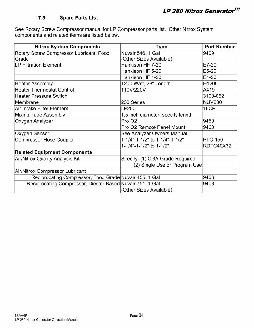
LP 280 Nitrox GeneratorTM 17.5 Spare Parts List
See Rotary Screw Compressor m or L arts list. Other Nitrox System omponents and related items are belo
ber
P Compressor pw.
anual f listedc
Nitrox System Components Type Part Num
Rotary Screw Compressor Lubricant, Food Nuvair 546, 1 Gal rade (Other Sizes Available)
09 94GLP Filtration Element Hankison HF 7-20 E7-20 Hankison HF 5-20 E5-20 Ha
eater Assembly nkison HF 1-20 E1-20
HH
1200 Watt, 28" Length H1200 e 110V/220V A419 ater Thermostat Control
He 3100-052 ater Pressure Switch rane Memb 230 Series NUV230
Air LP280 16CP Intake Filter Element Mixing Tube Assembly 1.5 inch diameter, specify length Oxygen Analyzer Pro O2 9450 Pro O2 Rem l M ote Pane ount 9460Oxygen Sensor See Analyzer Owners Manual Compressor Hose Coupler 1-1/4"-1-1/2" to 1-1/4"-1-1/2" PTC-150
1-1/4"lated Equipment Components Nitrox Quality Analysis Kit
Nitrox Compressor Lubricant Recip
-1-1/2" to 1-1/2" RDTC40X32 Re Air/ Specify: (1) CGA Grade Required
(2) Single Use or Program Use Air/
rocating Compressor, Food Grade Nuvair 45 9406 5, 1 Gal Reciprocating Compressor, Diester Based Nuvair 751, 1 Gal 9403
(Othe
r Si zes Available)
NUVAIR Page 34 LP 280 Nitrox Generator Operation Manual

LP 280 Nitrox GeneratorTM 17.6 Service Record Log
Date Technician Name Service Performed
NUVAIR Page 35 LP 280 Nitrox Generator Operation Manual
LP 280 Nitrox GeneratorTM Appen
pply pecifications
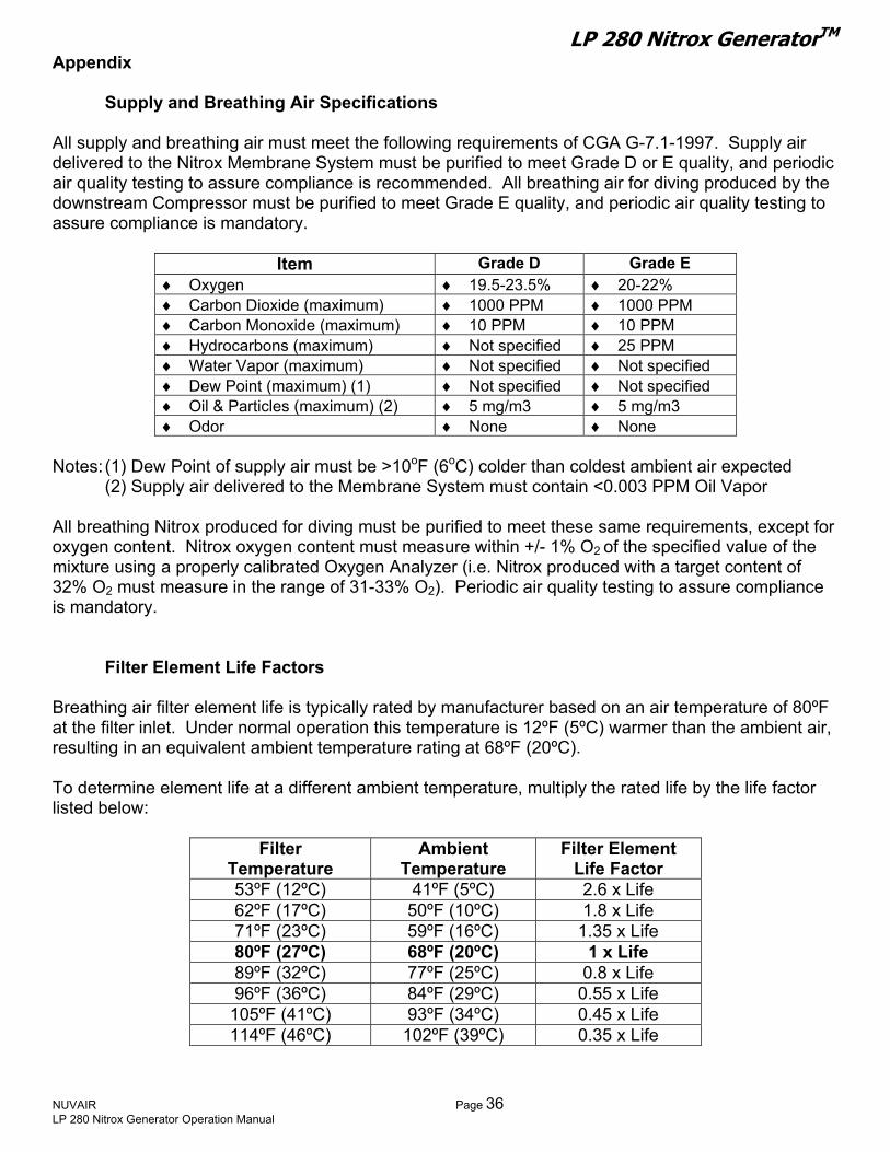
All supply and breathing air must meet the following requirements of CGA G-7.1-1997. Supply air delivered to the Nitrox Membrane System must be purified to meet Grade D or E quality, and periodic air quality testing to assure compliance is recommended. All breathing air for diving produced by the downstream Compressor must be purified to meet Grade E quality, and periodic air quality testing to assure compliance is mandatory.
Item Grade D Grade E
dix
Su and Breathing Air S
umimm
1) m
m
ist :
♦ Oxygen ♦ 19.5-23.5% ♦ 20-22% ♦ Carbon Dioxide (maxim ) ♦ 1000 PPM ♦ 1000 PPM ♦ Carbon Monoxide (max um) ♦ 10 PPM ♦ 10 PPM ♦ Hydrocarbons (maximu ) ♦ Not specified ♦ 25 PPM ♦ Water Vapor (maximum) ♦ Not specified ♦ Not specified ♦ Dew Point (maximum) ( ♦ Not specified ♦ Not specified ♦ Oil & Particles (maximu ) (2) ♦ 5 mg/m3 ♦ 5 mg/m3 ♦ Odor ♦ None ♦ None
Notes: (1) Dew Point of supply air must be >10oF (6oC) colder than coldest ambient air expected (2) Supply air delivered to the Membrane System must contain <0.003 PPM Oil Vapor All breathing Nitrox produced for diving must be purified to meet these same requirements, except for oxygen content. Nitrox oxygen content ust measure within +/- 1% O2 of the specified value of the mixture using a properly calibrated Oxygen Analyzer (i.e. Nitrox produced with a target content of 32% O2 must measure in the range of 31-33% O2). Periodic air quality testing to assure compliance is mandatory.
Filter Element Life Factors Breathing air filter element life is typically rated by manufacturer based on an air temperature of 80ºF at the filter inlet. Under normal operation this temperature is 12ºF (5ºC) warmer than the ambient air, resulting in an equivalent ambient temperature rating at 68ºF (20ºC). To determine element life at a different ambient temperature, multiply the rated life by the life factor l ed below
Filter Temperature
Ambient Temperature
Filter Element Life Factor
53ºF (12ºC) 41ºF (5ºC) 2.6 x Life 62ºF (17ºC) 50ºF (10ºC) 1.8 x Life 71ºF (23ºC) 59ºF (16ºC) 1.35 x Life 80ºF (27ºC) 68ºF (20ºC) 1 x Life 89ºF (32ºC) 77ºF (25ºC) 0.8 x Life 96ºF (36ºC) 84ºF (29ºC) 0.55 x Life 105ºF (41ºC) 93ºF (34ºC) 0.45 x Life 114ºF (46ºC) 102ºF (39ºC) 0.35 x Life
NUVAIR Page 36 LP 280 Nitrox Generator Operation Manual
LP 280 Nitrox GeneratorTM
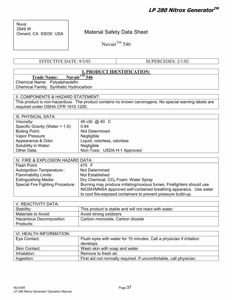
ir est 5th St. Material Safety Data Sheet
NuvairTM 546
/03 SUPERCEDES: 2/1/02 EFFECTIVE DATE: 9/3
Ph: 1-805-815-4044 Fax: 1-805-815-4196
I. PRODUCT IDENTIFICATION:
e N me: Nuvair 546a e: Polyalphaolefin ily: Synthetic Hydrocarbon
NT & HAZARD STATEMEN non-hazardous. The product no known carcinoge s. No special warni
r OSHA CFR 1910.1200.
Trad TM
Chemical Nam Chemical Fam
II. COMPONE S T: This product is contains n ng labels are required unde
III. PHYSICAL DATA: Viscosity: 46 cSt. @ 40�C Specific Gravity (Water = 1.0): 0.84 Boiling Point: Not Determined Vapor Pressure: Negligible Appearance & Odor: Liquid, colorless, odorless Solubility in Water: Negligible Other Data: Non-Toxic USDA H-1 Approved
IV. FIRE & EXPLOSION HAZARD DATA: Flash Point: 475�F Autoignition Temperature:: Not Determined Flamm Established ability Limits: NotExtinguishing Media: Dry Chemical; CO2 Foam; Water Spray Special Fire Fighting Procedure: Burning may produce irritating/noxious fumes. Firefighters should use
NIOSH/MNSA approved self-contained breathing apparatus. Use water to cool fire-exposed containers to prevent pressure build-up.
V. REACTIVITY DATA: Stability: This product is stable and will not react with water. Materials to Avoid: Avoid strong oxidizers Hazardous Decomposition Products:
arbon monoxide, Carbon dioxide C
ION: FlusdevWas th soap and waRem sh air. Firs ormally require mfortable, ca
VI. HEALTH INFORMATEye Contact: h eyes with water for 15 minutes. Call a physician if irritation
elops. Skin Contact: h skin wi ter. Inhalation: ove to freIngestion: t aid not n d. If unco ll physician.
Nuva2949 Oxnard, CA 93030 USA
W
NUVAIR Page 37 LP 280 Nitrox Generator Operation Manual

LP 280 Nitrox GeneratorTM
EFFECTIVE DATE: 9/3/03 SUPERCEDES: 2/1/02 PRODUCT: Nuvai
VII. HEALTH HAZARD
rTM 546
DATA: Exposure Limits: Not applicable Effects of Overexposure: Low oral and dermal toxicity. Prolonged or repeated exposure may cause
n, nausea, and vomiting. irritatio VII. EMPLOYEE PROTECTION: For gene thoroughly after handling material. Avoid contact with skin and
ded for prolonged exposure.
ral personal hygiene, wash handseyes. Chemical impervious gloves are recommenUse in a well ventilated area
VIII. STORAGE, SPILL & DISPOSAL PROCEDURES: Storage: Store in clean, dry area. Spills: Use absorbent materials to soak up fluid. Disposal: Incinerate this product and all associated wastes in a licensed facility in
ederal, state, and local regulations. accordance with F
IX. HAZARD RATING INFORM ON: NFPA KEY
Health: 1 4=Severe 0=Minimal Flammability: 1 3=Serious Reactivity: O 2=Modera
ATI
te B=Gloves,Goggles Personal Protection: B 1=Slight
erein i ta available to us and is believed to be true and kes no warran implied, regarding the accuracy of this data or the results e use thereo jury from the use of this product.
This information contained h s based on the daaccurate. Nuvair ma ty, expressed or to be obtained from th f. Nuvair assumes no responsibility for in
For Additional Information:
t 5 St. USA
-815-4196 ww.nuvair.com
Nuvair th2949 Wes
Oxnard, CA 93030 Ph: 1-805-815-4044 Fax: 1-805Website: w E-mail: [email protected]
NUVAIR Page 38 LP 280 Nitrox Generator Operation Manual

LP 280 Nitrox GeneratorTM Nuvair™ 455 Premium Synthetic Food rade Air/Nitrox Compressor LubricantG
E
Product Identification: Trade Name: …………………………………. Nuvair 455 Chemical Name: …………………………...... Polyalphaolefin
………...….. Synthetic hydrocarbon mix II. Components & Hazard Statement:
rdous. Trequired under OSHA CFR 1910.12 21 CFR 178.3570 regarding lubricants for incidental food contact.
ng Point: ................................................ N.A.
....................... Clear – with little odor Solubility in Water: ....................................... Negligible
Iint: .....................................tion Temperature: ...............ility Limits: ........................hing Media: ......................
Special Fire Fighting Procedure: … ighters should use NIOSH/MNSA approved self-contained breathing apparatus. Use water to cool fire-exposed containers to prevent pressure build-up.
V. Reactivity Data: ty: ………………….…………………... This product is st not react with w
void: ...................................... Avoid strong oxidecomposition Products: …...... Carbon monoxide e
VI. Health Information: ................................. F with water for 15 minutes. Call physician if irritation develops.
Skin Contact: ............................................... Wash skin with soap and water. Inhalation: .................................................... Remove to fresh air.
V
cause irritation, nausea, and vomiting. III. Employee Protection:
For general personal hygiene, wash hands thoroughly after handling material. Avoid contact with skin and eyes. are not required, but may be recommended for prolonged exposure. Use in a well
ted area. I isposal Procedures:
…………………. Store in clean, dry area. ………………………. Use absorbent materials to soak up fluid.
…………………… Incinerate this product and all associated wastes in a licensed facility in accordance with Federal, state, and local regulations.
X………………….. 1
Flammability: ……..................... 1 Reactivity: ……………….….….. 0 Personal Protection: ………….. B
This information contained herein is based on the data available to us and is believed to be true and accurate. Nuvair makes no warranty, expressed or implied, regarding the accuracy of this data or the results to be obtained from the use thereof. Nuvair assumes no responsibility for injury from the use of this product.
ffective Date: 7/8/2003 I.
Chemical Family: ………………
This product is non-haza he product contains no known carcinogens. No special warning labels are 00. This product complies with FDA
III. Physical Data: Viscosity: ...................................................... 70 cst. @40°C Specific Gravity (Water = 1.0): ..................... 0.83 – 0.85 BoiliVapor Pressure: ........................................... Negligible Appearance & Odor: .............
V. Fire & Explosion Hazard Data: Flash po
igni............. 490°F COC
Auto ............ Not Established FlammabExtinguis
............. Not Established ............. Dry Chemical; CO2 Foam; Water Spray ……….. Burning may produce irritating/noxious fumes. Firef
Stabili able and will ater. Materials to A
s Dizers
Hazardou , Carbon dioxid
Eye Contact: .............. lush eyes
Ingestion: ..................................................... First aid not normally required. If uncomfortable, call physician. II. Health Hazard Data:
Exposure Limit: ............................................ Not Applicable Effects of Overexposure: ……………………. Low oral and dermal toxicity. Prolonged or repeated exposure may
V
Chemical impervious glovesventila
X. Storage, Spill, & DStorage: ……………………Spills: …………………Disposal: …………………
. Hazard Rating Information: NFPA Health: ………
NUVAIR Page 39 LP 280 Nitrox Generator Operation Manual
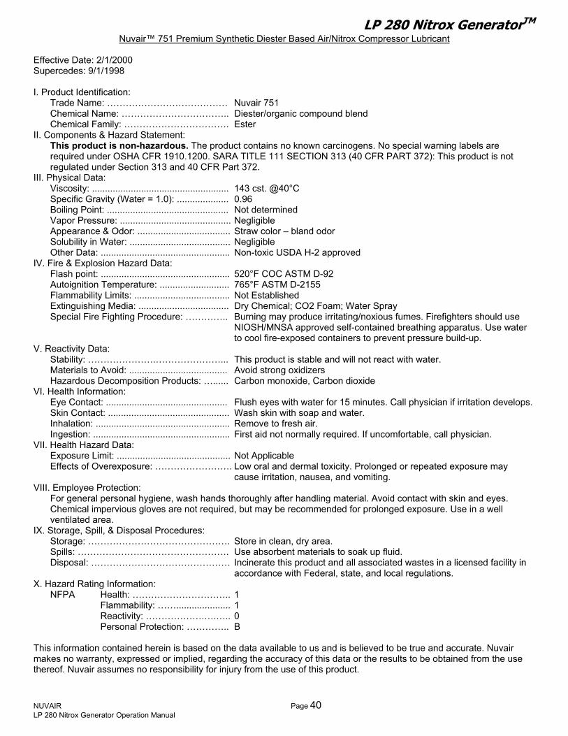
LP 280 Nitrox GeneratorTM Nuvair™ 751 Premium Synthetic Diester Based Air/Nitrox Compressor Lubricant
upercedes: 9/1/1998
I. P
……. Ester II. C
FR 1910.1200. SARA TITLE 111 SECTION 313 (40 CFR PART 372): This product is not r Section 313 and 40 CFR Part 372.
III. P°C
ined
– bland odor .................. Negligible
DA H-2 approved IV. F
M D-92
Extinguishing Media: ................................... Special Fire Fighting Procedure: ………….. uld use
NIOSH/MNSA approved self-contained breathing apparatus. Use water build-up.
V. Ract with water.
..................................... Avoid strong oxidizers
VI. H for 15 minutes. Call physician if irritation develops.
................................... Remove to fresh air. mally required. If uncomfortable, call physician.
VII.Exposure Limit: ............................................
: ……………………. Low oral and dermal toxicity. Prolonged or repeated exposure may
VIII.onal hygiene, wash hands thoroughly after handling material. Avoid contact with skin and eyes.
uired, but may be recommended for prolonged exposure. Use in a well
IX.
Spills: …………………………………………. ………………… Incinerate this product and all associated wastes in a licensed facility in
nce with Federal, state, and local regulations. X. Hazard Ratin
NFPA
Reactivity: ……………….….….. 0
eved to be true and accurate. Nuvair makes no warranty, expressed or implied, regarding the accuracy of this data or the results to be obtained from the use thereof. Nuvair assumes no responsibility for injury from the use of this product.
Effective Date: 2/1/2000 S
roduct Identification: Trade Name: ………………………………… Nuvair 751 Chemical Name: …………………………….. Diester/organic compound blend Chemical Family: ………………………omponents & Hazard Statement: This product is non-hazardous. The product contains no known carcinogens. No special warning labels are required under OSHA Cregulated undehysical Data: Viscosity: ..................................................... 143 cst. @40Specific Gravity (Water = 1.0): .................... 0.96 Boiling Point: ............................................... Not determVapor Pressure: ........................................... Negligible Appearance & Odor: .................................... Straw colorSolubility in Water: .....................Other Data: .................................................. Non-toxic USire & Explosion Hazard Data:
Flash point: .................................................. 520°F COC ASTAutoignition Temperature: ........................... 765°F ASTM D-2155 Flammability Limits: ..................................... Not Established
Dry Chemical; CO2 Foam; Water Spray Burning may produce irritating/noxious fumes. Firefighters sho
to cool fire-exposed containers to prevent pressure eactivity Data: Stability: ………………….…………………... This product is stable and will not reMaterials to Avoid: .Hazardous Decomposition Products: …...... Carbon monoxide, Carbon dioxide ealth Information:
Eye Contact: ............................................... Flush eyes with waterSkin Contact: ............................................... Wash skin with soap and water. Inhalation: .................Ingestion: ..................................................... First aid not nor
Health Hazard Data: Not Applicable
Effects of Overexposurecause irritation, nausea, and vomiting.
Employee Protection: For general persChemical impervious gloves are not reqventilated area.
Storage, Spill, & Disposal Procedures: Storage: ………………………………………. Store in clean, dry area.
Use absorbent materials to soak up fluid. Disposal: ……………………
accordag Information: Health: ………………………….. 1 Flammability: ……..................... 1
Personal Protection: ………….. B
This information contained herein is based on the data available to us and is beli
NUVAIR Page 40 LP 280 Nitrox Generator Operation Manual

LP 280 Nitrox GeneratorTM OWNER’S WARRANTY RESPONSIBILITIES
prevent equipment damage by complying with the procedures outlined below and in the
l void the Nitrox System warranty.
Ins
Failure of the owner to Operation Manual wil
tallation: • All set up requirements and procedures provided in the Nitrox System Operation Manual must be
nliness, Compressor preparation, and installation of
ent
Compressor for compressing Nitrox, contact onnect your Nitrox System.
ressing Nitrox, all traces of the old Lubricant must ssor Lubricant approved by Nuvair.
ied electrician in accordance with all
ontrol. Changes in temperature brane damage.
ntake Hose provided. If a longer hose is
Op
followed in their entirety including supply air cleathe Nitrox System.
• Supply air to the Membrane must be properly filtered to CGA Grade D air quality or better to prevdamage to the Membrane. Air quality testing of the supply air should be performed periodically and documented to assure compliance.
If there is any doubt regarding the suitability of a HP efore you c
•Nuvair or the Compressor manufacturer b
• If an existing HP Compressor is to be used for compbe removed and replaced with a Nitrox Compre
• Electrical wiring and connections should be made by a qualifnational and local electrical codes.
• Do not change the temperature setting on the Heater Thermostat Csettings may cause Mem
• To prevent Compressor damage, only use the Compressor Irequired, contact Nuvair for assistance.
eration: ly a HP Compressor with Nitrox mixtures containing more than ncentrations of oxygen may cause severe Compressor
• Do not use the Nitrox System to supp40% oxygen. Compressing higher co damage.
p Nitrox mixtures at pressures above the compressor manufacturer’s rating, and never ompressor
e tank condensate on a daily
Ma
• Do not pumabove 3600 P.S.I. Compressing Nitrox at higher pressures may cause severe HP Cdamage.
mbrane damage, drain all low pressure filter and volum• To prevent Mebasis.
intenance: • Change low pressure filter elements on a schedule determined by filter capacity and ambient
temperature and humidity. Contact Nuvair if you need assistance establishing a schedule for your
ts, fittings, connectors, and clamps tight. anty
cient e. Proof of maintenance may be required prior to determining the validity of a warranty
equipment and location. • Replace Membrane System Air Intake Filter on a regular basis to prevent flow obstruction. • Keep all nuts, bol• Keep a service record book showing that regular maintenance work has been carried out. If a warr
claim becomes necessary, it will aid in demonstrating that damage has not been caused by insuffimaintenancrequest.
NUVAIR Page 41 LP 280 Nitrox Generator Operation Manual

LP 280 Nitrox GeneratorTM NUVAIR NITROX SYSTEM WARRANTY
NUVAIR extends a limited warranty, which warrants the Nitrox System to be free from defects in materials and workmanship under normal use and service for a limited period. The specific Membrane Component of the
itrox System is warranted according to the pro-rated terms as set forth below. All other Original Equipment (OEM) components used in the system are warranted only to the extent of the OEM’s warranty to
NUVAIworkmnot tran NUVAIwhich f do not exhibit any signs of improper maintenance, misuse, acc nDeterm customer to ade a they ar l be void and NUVAI from the use pproved by NUVAIR. Pro-Ra
NManufacturer
R. NUVAIR makes no warranty with respect to these OEM components, and only warrants the anship that NUVAIR has employed in the installation or use of any OEM component. This warranty is sferable.
R will, at it’s discretion and according to the terms as set forth within, replace or repair any materials ail under normal use and service and
ide t, alteration, weather damage, tampering, or use for any other than the intended purpose. ination of failure is the responsibility of NUVAIR, which will work together with the
qu tely address warranty issues. When any materials are repaired or replaced during the warranty period,e warranted only for the remainder of the original warranty period. This warranty shalR shall have no responsibility to repair or replace damaged materials resulting directly or indirectly of repair or replacement parts not a
ted Terms: NUVAIworkm e of installation or forty-two (42) months from date of hipme t. The warranty covers parts only and is prorated as follows:
•
A warranty registration card, supplied with system documentation, must be filled out and submitted to NUVAIR for insta a
ems:
R warrants the Membrane Component of the Nitrox System to be free from defects in material and anship for a period of thirty-six (36) months from datnt by NUVAIR, whichever may occur firss
• First Year Repair or replacement free of charge
Second Year Warranty allowance of 70% of the current Membrane Component list price • Third Year Warranty allowance of 40% of the current Membrane Component list price
the warranty to be in full effect. If the warranty registration card is not received within thirty (30) days of ll tion, the thirty-six (36) month warranty will begin with the date of shipment from NUVAIR.
Maintenance ItAny
o them,
are n and consum . Re n
materials which are consumed, or otherwise rendered not warrantable due to processes applied t co sidered expendable and are not covered under the terms of this policy. This includes maintenance
able items listed as part of a suggested maintenance program included with system documentation
tur Policy: lic tion for warranty service can be made by contacting NUVAIApp a R during regular business hours and
req sfreight NUVAI d to the c ia NUVAIR’s preferred shipping method, at NUVAIR’s expense. Any expedited return shipping arrangements to be made at customer’s expense must be specified in advance. Limitation of Warranty and Liability:
ue ting a Return Material Authorization number. Materials that are found to be defective must be shipped, pre-paid, to the NUVAIR office in Oxnard, California. Upon inspection and determination of failure, R shall exercise its options under the terms of this policy. Warranty serviced materials will be returneustomer v
Repair, replacement or refund in the manner and within the time provided shall constitute NUVAIR’S sole liability and the Purchaser’s exclusive remedy resulting from any nonconformity or defect. NUVAIR shall not in any event be liable for any damages, whether based on contract, warranty, negligence, strict liability or otherwise, including without limitation any consequential, incidental or special damages, arising with respect to the equipment or its failure to operate, even if NUVAIR has been advised of the possibility thereof. NUVAIR makes no other warranty or representation of any kind, except that of title, and all other warranties, express or implied, including warranties of merchantability and fitness for a particular purpose, are hereby expressly disclaimed. No salesman or other representative of NUVAIR has authority to make any warranties.
NUVAIR Page 42 LP 280 Nitrox Generator Operation Manual

LP 280 Nitrox GeneratorTM

LP 280 Nitrox GeneratorTM
Nuvair™ 2004 All Rights Reserved Phone (805) 815-4044
Fax (805) 815-4196 2949 West 5th Street
Oxnard, CA 93030 USA
Email : [email protected] Web : www.nuvair.com
GD Revision 0206