lp solidstart lsl & lvl wall framing technical guide · lp solidstart lsl & lvl wall...
TRANSCRIPT

Please verify availability with the LP SolidStart Engineered Wood Products distributor in your area prior to specifying these products.
U.S. Technical Guide
LP SolidStart LSL & LVL
Wall Framing Technical Guide1730Fb-1.35E and 2360Fb-1.55E LSL
2250Fb-1.5E and 2900Fb-2.0E LVL

2
Introduction
Architects are raising the roof and stretching walls beyond
the reach of conventional lumber. LP® SolidStart® LSL and
LVL studs redefine the standard for wall framing by providing
structural walls that can be straighter, taller and stronger for
both conventional and challenging engineered applications.
Because LP manufactures its LSL and LVL to the highest
standards, builders know that they’ll get fewer callbacks and
save themselves time and money.
Where traditional lumber studs warp, bow and twist as they
dry, LP SolidStart LSL and LVL won’t because they start dry from
the mill. Having straight walls gives home-owners the peace of
mind that their cabinets will stay flush to the wall, their tile and
drywall is less likely to crack and their windows and doors will
function properly. That’s performance you can count on.
Using this technical guide, LP SolidStart LSL and LVL can be
specified for use in conventional (prescriptive) and engineered
wood-frame wall construction.
CONVENTIONAL CONSTRUCTION Conventional construction provisions for wood-frame walls
are included in the International Building Code (IBC) and the
International Residential Code (IRC). In conventional construction,
wall members and their connections are selected from tables in
the Code rather than being calculated, as in engineered design.
LP’s compliance with the ICC Evaluation Service’s Acceptance
Criteria for Wood-Based Studs (AC202) permits LP SolidStart LSL
and LVL to be a direct substitution to traditional lumber studs
prescribed in Section 2308.9 of the IBC and Section R602 of the IRC.
Compliance with AC202 also demonstrates equivalence to
the notching provisions prescribed in the Code for traditional
lumber studs in conventional construction.
FIRE-RESISTIVE WALL CONSTRUCTIONLP SolidStart LSL and LVL (1.5E and higher) are permitted
to be used in the 1-hour fire-resistance-rated wall assemblies
listed in Table 721.1(3) of the IBC, with some additional design
and construction considerations as specified in LP’s evaluation
and product reports. When used in prescriptive wall framing,
LP SolidStart LSL and LVL can be directly substituted for the
equivalent size of No 2 or lower grade dimensional lumber.
When used in engineered wall construction, some additional
limitations are imposed on the load capacity of the studs. For
both prescriptive and engineered wall systems, mineral wool
insulation is required in the wall cavity. Please refer to ICC-ES
evaluation report ESR-2403 and APA product report PR-L280 for
complete information on the use of LP SolidStart LSL and LVL in
fire-resistance-rated walls, or use LP’s Wood-E Design software.
ENGINEERED DESIGN CONSTRUCTIONIn engineered design, calculations based on the expected
in-service loads are performed to ensure that the allowable
capacities of the wall members are not exceeded.
Notches and holes in LP SolidStart LSL and LVL wall framing
are permitted when designed in accordance with the provisions of
the National Design Specification for Wood Construction (NDS),
with additional adjustments as prescribed herein. The wall stud
and exterior wall column tables in this guide include the effects
of notches and holes on their capacity. Refer to Drilling & Notching
on page 4 for the limitations of notch and hole size and location.
DEFLECTION LIMITSLike floor and roof systems, walls are subject to code-
prescribed deflection limits as well as industry recommendations.
The IBC prescribes a deflection ratio limit of L/240 for walls
with brittle finishes and L/120 for walls with flexible finishes.
The IRC prescribes the additional ratio of L/360 for walls with
stucco or plaster. Additional deflection limits are recommended
for certain windows and wall finishes like brick. Always verify
the requirements, but the following table summarizes common
deflection limits.
LIFETIME LIMITED WARRANTYLP SolidStart Engineered Wood Products are backed by a
lifetime limited warranty. Visit LPCorp.com or call 1.888.820.0325
for a copy of the warranty.
A Word About Wall Framing
Condition DeflectionFlexible Finish (IBC) L/120
Windows & Doors L/175
Brittle Finish (IBC) L/240
Plaster & Stucco (IRC) L/360
Brick L/600

3
Table of Contents
Product Specifications, Design Values and Drilling & Notching . . . . . . . . . . . . . . . . . . . . . 4
Wall Stud Capacity (plf) . . . . . . . . . . . . . . . . . . . . . 5
Exterior Wall Column Capacity (lbs): 115 mph IBC 2012 (90 mph IRC 2012), Exposure B . . . . . . . 6
Exterior Wall Column Capacity (lbs): 130 mph IBC 2012 (100 mph IRC 2012), Exposure C . . . . . . 7
Exterior Wall Column Capacity (lbs): 115 mph IBC 2012 (90 mph IRC 2012), Exposure B . . . . . . . 8
Exterior Wall Column Capacity (lbs): 130 mph IBC 2012 (100 mph IRC 2012), Exposure C . . . . . . 9
Exterior Wall Column Capacity (lbs): 115 mph IBC 2012 (90 mph IRC 2012), Exposure B . . . . . . 10
Exterior Wall Column Capacity (lbs): 130 mph IBC 2012 (100 mph IRC 2012), Exposure C . . . . . 11
Typical Wall Framing & Wall Stud Example . . . . . . . . . 12
Typical Wall Framing: Trimmer & King Stud Examples . . . 13
Typical Wall Framing: Wall Column Examples . . . . . . . 14
Free-Standing Interior Column Capacity (lbs) . . . . . . . 15
Nailing and Connection Details . . . . . . . . . . . . . . 16-17
Typical Connections . . . . . . . . . . . . . . . . . . . . . . . 18
Handling and Storage Guidelines . . . . . . . . . . . . . . . 19

4
BEARING CAPACITYStud or Column
Size
Column Bearing (lbs) Stud Bearing (plf)Hem-Fir (405 psi)
SPF (425 psi)
LP LSL/LVL (450 psi)
Concrete (2500 psi)
Hem-Fir (405 psi) SPF (425 psi)12" oc 16" oc 12" oc 16" oc
1-1/2" x 3-1/2" 2125 2230 2360 4460 2125 1590 2230 16701-1/2" x 5-1/2" 3340 3505 3710 7010 3340 2505 3505 26251-1/2" x 7-1/4" 4400 4620 4890 9240 4400 3300 4620 34651-1/2" x 9-1/4" 5615 5895 6240 11790 5615 4210 5895 44203-1/2" x 3-1/2" 4960 5205 5510 104103-1/2" x 5-1/2" 7795 8180 8660 163603-1/2" x 7-1/4" 10275 10780 11415 215653-1/2" x 9-1/4" 13110 13755 14565 275155-1/4" x 5-1/2" 11690 12270 12990 245405-1/4" x 7-1/4" 15415 16175 17125 323505-1/4" x 9-1/4" 19665 20635 21850 41275
7" x 5-1/2" 15590 16360 17325 327257" x 7-1/4" 20550 21565 22835 431357" x 9-1/4" 26220 27515 29135 55035
DRILLING & NOTCHING
Product Specifications, Design Values and Drilling & Notching
ALLOWABLE DESIGN STRESSES (PSI)
Material Grade
Beam (Edgewise) Orientation Plank (Flatwise) Orientation Axial
Bending Fb
3, 4, 6
Modulus of Elasticity
MOE9
Shear Fv
Compression perpendicular-to-grain
Fc?
Bending Fb
5
Modulus of Elasticity
MOE9
Shear Fv
Compression perpendicular-to-grain
Fc?
Tension Ft
7, 8Compression
Fc
LP® SolidStart® LSL1730Fb-1 .35E 1730 1 .35 x 106 410 750 1910 1 .35 x 106 155 685 9 1300 16502360Fb-1 .55E 2360 1 .55 x 106 410 875 2620 1 .55 x 106 155 685 9 1750 2175
LP SolidStart LVL2250Fb-1 .5E 2250 1 .5 x 106 285 750 2200 1 .4 x 106 140 450 1350 23502900Fb-2 .0E 2900 2 .0 x 106 285 750 2950 2 .0 x 106 140 550 1800 3200
NOTES:1. LP SolidStart LSL and LVL shall be designed for dry-use conditions only. Dry-use applies to products installed in dry, covered and well ventilated interior
conditions in which the equivalent moisture content in lumber will not exceed 16%. Adjustments for high temperature are beyond the scope of this guide.2. The allowable strengths and stiffness are for normal load duration (10 year). Bending, Shear and Axial Tension and Compression shall be adjusted
according to code. Modulus of Elasticity and Compression perpendicular-to-grain shall not be adjusted for load duration.3. The allowable Bending, Fb, for LP SolidStart LSL in the Beam orientation is tabulated for a standard 12" depth.
For depths other than 12," multiply Fb by (12/depth)0.143. For depths less than 3-1/2", adjust Fb by 1.193.4. The allowable Bending, Fb, for LP SolidStart LVL in the Beam orientation is tabulated for a standard 12" depth.
For depths less than 12," multiply Fb by (12/depth)0.111. For depths less than 3-1/2," multiply Fb by 1.147. For depths greater than 12," multiply Fb by (12/depth)0.143.
5. The allowable Bending, Fb, in the Plank orientation shall not be adjusted for depth (thickness).6. The allowable edgewise Bending shall also be multiplied by the repetitive member factor, Cr = 1.04, when 3 or more pieces are properly connected
in direct contact or are used as wall studs spaced no more than 24" oc and properly connected together by an adequate wall sheathing.7. The allowable Tension, Ft, for LP SolidStart LSL is assigned for a standard length of 3 feet. For lengths longer than 3 feet, multiply Ft by (3/length)0.092.
For lengths less than 3 feet, use the design tension stresses in the table above, unadjusted.8. The allowable Tension, Ft, for LP SolidStart LVL is assigned for a standard length of 3 feet. For lengths longer than 3 feet, multiply Ft by (3/length)0.111.
For lengths less than 3 feet, use the design tension stresses in the table above, unadjusted.9. Reference compression perpendicular-to-grain design values in the plank orientation for LP SolidStart LSL are assigned at the proportional limit strain
of 0.0292. The NDS bearing area factor Cb shall not be applied.10. Deflection calculations for LP SolidStart LSL and LVL shall include both bending and shear deformations.
Deflection for wall framing, uniform load: ∆ = + Where: ∆ = deflection (in) E = modulus of elasticty (from table) w = uniform load (plf) b = width (in) L = design span (ft) d = depth (in direction of bending) (in)
NOTES:1. The capacity for Wood Bearing is based on the compression strength,
perpendicular-to-grain, of the bearing plate and shall not be adjusted for load duration. The allowable compression, perpendicular-to-grain, for other species of lumber can be found in the 2012 edition of the National Design Specification for Wood Construction (NDS).
2. The Bearing Capacity for concrete is based on a conversion to allowable stress design for comparison to the column capacities in this guide.
3. To determine the Bearing Capacity of a multiple-ply member (such as a double 2 x 4 stud), multiply the Bearing Capacity from the table by the number of plies. The capacity is additive and may be increased for bearing on wood plates per note 4.
4. When a stud or column is located at least 3" from the end of a wall plate, the Bearing Capacities above are permitted to be increased by the bearing area factor, Cb = (Lb + 0.375)/Lb, where Lb is the bearing length measured parallel to the grain of the wall plate and is less than 6." For bearing lengths 6" or more, Cb = 1.00.
NOTES:1. Free-standing columns shall not be drilled or notched except as required for proper installation of column caps,
bases or other hold-downs without further analysis by a professional engineer. Bolts, lag screws and self-tapping screws shall only be inserted through the face of the column, perpendicular to the face of the strands in LP LSL and the veneers in LP LVL.
2. Cutting, notching and boring of nominal 2x4 (1-1/2" x 3-1/2") and 2x6 (1-1/2" x 5-1/2") LP LSL and LP LVL wall studs used in prescriptive wall framing is permitted in accordance with sections 2308.9.10 and 2308.9.11 of the IBC and section R602.6 of the International Residential Code (IRC).
3. For wall applications designed with the tables in this guide, notching and drilling shall be limited to the restrictions of notes 4 through 6 (see details to left).
4. One hole up to 40% of the stud depth, maximum of 2-3/16," is allowed only in the upper or lower 3 feet or 1/3 of the stud height, h (see Drilling and Notching detail for maximum hole sizes), except do not place a hole within 6" of either end of the stud. Two small holes up to 1" diameter and vertically spaced no closer than 12" oc are permited in studs with a depth of at least 5-1/2."
5. One notch up to 25% of the stud depth, maximum of 1-3/8," is allowed only in the upper or lower 3 feet or 1/3 of the stud height, h (see Drilling and Notching detail for maximum notch sizes), except do not place a notch within 6" of either end of the stud. The notch length shall not exceed 3-1/2."
6. Do NOT cut a hole and a notch at the same cross-section. Maintain a clear vertical separation of at least twice the length of the notch or twice the diameter of the hole, whichever is greater.
7. For engineered wall applications beyond the scope of this guide, design for notching and drilling shall be based on a net section analysis in accordance with the provisions of the 2012 NDS and with the restrictions listed in APA product report PR-L280 and ICC-ES evaluation report ESR-2403. The allowable design stresses for bending, axial compression and axial tension shall be reduced by the Strength Reduction Factors (tabulated below) to account for stress concentrations.
270wL4 28.8wL2
Ebd3 Ebd
PRODUCT ORIENTATION
Beam (Edgewise)
b d
No
Not
ches
or H
oles
!H
oles
/Not
ches
Pe
rmitt
edH
oles
/Not
ches
Pe
rmitt
ed
Less
or o
f 3' a
nd h
/3
6"
h
Maximum Notch Depth 7/8" for 2x4 1-3/8" for 2x6 and wider
Maximum Hole Diameter 1-3/8" for 2x4 2-3/16" for 2x6 and wider
5/8" min . edge distance
3-1/
2" m
ax .
6"
STRENGTH REDUCTION FACTORS
MaterialNotch Hole
Bending Compression Tension Bending Compression TensionLP SolidStart LSL 0 .95 0 .90 0 .75 1 .00 1 .00 1 .00LP SolidStart LVL 0 .80 0 .90 0 .60 0 .95 0 .95 0 .95
n/a
Less
or o
f 3' a
nd h
/3
2x L
arge
r of H
ole
or
Not
ch L
engt
h2x
Lar
ger o
f Hol
e
or N
otch
Len
gth
Plank (Flatwise)
b d
Equations for other conditions can be found in engineering references.

5
Wall Stud Capacity (plf)
115 MPH IBC 2012 (90 MPH IRC 2012), EXPOSURE B
Height Stud Spacing
1.35E LP LSL 1.55E LP LSL or 1.5E LP LVL 2.0E LP LVL1-1/2" x 3-1/2" 1-1/2" x 5-1/2" 1-1/2" x 7-1/4" 1-1/2" x 9-1/4" 1-1/2" x 3-1/2" 1-1/2" x 5-1/2" 1-1/2" x 7-1/4" 1-1/2" x 9-1/4" 1-1/2" x 3-1/2" 1-1/2" x 5-1/2" 1-1/2" x 7-1/4" 1-1/2" x 9-1/4"
8' 12" 2900 L/713 4640 L/999 6110 L/999 7800 L/999 2950 L/793 4640 L/999 6110 L/999 7800 L/999 2950 L/999 4640 L/999 6110 L/999 7800 L/99916" 2180 L/535 3480 L/999 4580 L/999 5850 L/999 2210 L/594 3480 L/999 4580 L/999 5850 L/999 2210 L/793 3480 L/999 4580 L/999 5850 L/999
9' 12" 2480 L/511 4640 L/999 6110 L/999 7800 L/999 2850 L/567 4640 L/999 6110 L/999 7800 L/999 2950 L/757 4640 L/999 6110 L/999 7800 L/99916" 1740 L/383 3480 L/999 4580 L/999 5850 L/999 2100 L/425 3480 L/999 4580 L/999 5850 L/999 2210 L/567 3480 L/999 4580 L/999 5850 L/999
10' 12" 2040 L/378 4640 L/999 6110 L/999 7800 L/999 2430 L/420 4640 L/999 6110 L/999 7800 L/999 2950 L/561 4640 L/999 6110 L/999 7800 L/99916" 1380 L/284 3480 L/999 4580 L/999 5850 L/999 1690 L/315 3480 L/999 4580 L/999 5850 L/999 2210 L/420 3480 L/999 4580 L/999 5850 L/999
12' 12" 1370 L/225 4640 L/863 6110 L/999 7800 L/999 1670 L/250 4640 L/958 6110 L/999 7800 L/999 2370 L/333 4640 L/999 6110 L/999 7800 L/99916" 890 L/169 3480 L/647 4580 L/999 5850 L/999 1120 L/187 3480 L/719 4580 L/999 5850 L/999 1640 L/250 3480 L/958 4580 L/999 5850 L/999
14' 12" 960 L/145 3880 L/558 6110 L/999 7800 L/999 1180 L/161 4480 L/620 6110 L/999 7800 L/999 1710 L/215 4640 L/826 6110 L/999 7800 L/99916" - 2910 L/418 4580 L/947 5850 L/999 770 L/121 3360 L/465 4580 L/999 5850 L/999 1160 L/161 3480 L/620 4580 L/999 5850 L/999
16' 12" - 3210 L/382 6080 L/867 7800 L/999 - 3680 L/424 6110 L/963 7800 L/999 1270 L/146 4640 L/566 6110 L/999 7800 L/99916" - 2260 L/286 4560 L/650 5850 L/999 - 2720 L/318 4580 L/722 5850 L/999 - 3480 L/424 4580 L/963 5850 L/999
18' 12" - 2590 L/273 5230 L/622 7800 L/999 - 3060 L/303 6060 L/691 7800 L/999 - 4060 L/405 6110 L/921 7800 L/99916" - 1760 L/205 3920 L/466 5850 L/958 - 2140 L/227 4550 L/518 5850 L/999 - 3040 L/303 4580 L/691 5850 L/999
20' 12" - 2060 L/202 4520 L/461 7800 L/950 - 2470 L/225 5210 L/513 7800 L/999 - 3430 L/300 6110 L/684 7800 L/99916" - 1370 L/152 3390 L/346 5850 L/713 - 1690 L/168 3910 L/384 5850 L/792 - 2440 L/225 4580 L/513 5850 L/999
22' 12" - 1620 L/154 3940 L/352 6980 L/726 - 1970 L/171 4510 L/391 7800 L/807 - 2820 L/229 5980 L/522 7800 L/99916" - - 2810 L/264 5240 L/545 - 1330 L/128 3380 L/293 5850 L/605 - 1950 L/171 4480 L/391 5850 L/807
24' 12" - 1280 L/120 3350 L/275 6220 L/568 - 1590 L/134 3940 L/306 7210 L/631 - 2300 L/178 5230 L/408 7800 L/84216" - - 2290 L/206 4660 L/426 - - 2780 L/229 5410 L/473 - 1560 L/134 3920 L/306 5850 L/631
26' 12" - - 2790 L/219 5560 L/453 - - 3350 L/243 6420 L/503 - 1890 L/142 4600 L/325 7800 L/67116" - - 1870 L/164 4170 L/340 - - 2300 L/182 4810 L/377 - - 3310 L/243 5850 L/503
28' 12" - - 2330 L/177 5000 L/367 - - 2820 L/197 5740 L/408 - - 4010 L/263 7600 L/54416" - - 1530 L/133 3570 L/275 - - 1910 L/148 4300 L/306 - - 2790 L/197 5700 L/408
30' 12" - - 1950 L/146 4440 L/302 - - 2390 L/162 5160 L/336 - - 3430 L/216 6840 L/44816" - - - 3050 L/226 - - 1590 L/121 3700 L/252 - - 2360 L/162 5130 L/336
ADDITIONAL NOTES:1. Height is the clear height of the wall stud between the
bottom plate and the lower top plate.2. The first value in each cell represents the allowable vertical
load capacity of a single stud, in pounds per lineal foot of wall length (plf). These capacities are either the allowable capacity for vertical loads acting alone (no horizontal wind pressure) or the capacity of the stud after accounting for the bending induced by the horizontal wind pressure.
3. The second value in each cell represents the deflection ratio (L/x) based on the horizontal wind pressure. The designer shall verify the correct deflection ratio limit for the intended application.
4. Install full-width blocking per local code requirements, normally no more than every 8' along the height of the stud.
5. Do not use a product where designated “-” without further analysis by a professional engineer.
TO USE:1. Select the table for wind speed and exposure category.2. Determine the height of the wall stud. If not listed, select the next tallest Height in the table.3. Select the row for the desired Spacing.4. Select the LP® SolidStart® LSL or LVL grade and size where the Vertical Load Capacity and Deflection Ratio meet or exceed the applied vertical load and required deflection limit.5. Verify the plate bearing capacity for the selected stud. See Additional Note 9 below.
DESIGN ASSUMPTIONS:1. These tables are limited to structures with a mean roof height of 30'.2. The vertical load capacity is valid for wall columns supporting roof and floor loads. The design dead load shall not exceed
design live load. 3. The vertical capacity has been reduced to allow for holes and notches. Refer to the Drilling & Notching guidelines on
page 4 for more information.4. The vertical load capacity assumes an eccentricity of 1/6 of the wall thickness.5. The design wind pressures are based on Part 1, Chapter 30 of ASCE 7-10 for Components and Cladding,
Wall Zone 4, enclosed, and Risk Category II structure with topographic factor of Kzt = 1.00.6. A load duration adjustment, CD = 1.60, has been applied for wind.7. A repetitive member increase of 4% has been applied as allowed for 3 or more wall studs spaced no more than 24" oc,
properly connected by a suitable exterior sheathing. No increase in stiffness has been assumed for the wall sheathing.8. A gypsum wall board is assumed attached to the interior side of the studs.9. The tabulated capacities have been limited by the bearing capacity of LP SolidStart LSL or LVL as the wall plate (450 psi).
For plates with a bearing capacity less than 450 psi, the designer shall check the required vertical load against the bearing capacity for the plate and adjust the stud size and/or spacing accordingly. Refer to the Bearing Capacity table on page 4 for the common species of Hem-Fir and SPF. No increase is allowed without complete analysis of the vertical capacity of the wall stud.
130 MPH IBC 2012 (100 MPH IRC 2012), EXPOSURE C
Height Stud Spacing
1.35E LP LSL 1.55E LP LSL or 1.5E LP LVL 2.0E LP LVL1-1/2" x 3-1/2" 1-1/2" x 5-1/2" 1-1/2" x 7-1/4" 1-1/2" x 9-1/4" 1-1/2" x 3-1/2" 1-1/2" x 5-1/2" 1-1/2" x 7-1/4" 1-1/2" x 9-1/4" 1-1/2" x 3-1/2" 1-1/2" x 5-1/2" 1-1/2" x 7-1/4" 1-1/2" x 9-1/4"
8' 12" 2720 L/398 4640 L/999 6110 L/999 7800 L/999 2950 L/442 4640 L/999 6110 L/999 7800 L/999 2950 L/590 4640 L/999 6110 L/999 7800 L/99916" 1780 L/298 3480 L/999 4580 L/999 5850 L/999 2210 L/332 3480 L/999 4580 L/999 5850 L/999 2210 L/442 3480 L/999 4580 L/999 5850 L/999
9' 12" 2040 L/285 4640 L/999 6110 L/999 7800 L/999 2540 L/316 4640 L/999 6110 L/999 7800 L/999 2950 L/422 4640 L/999 6110 L/999 7800 L/99916" 1260 L/213 3480 L/811 4580 L/999 5850 L/999 1660 L/237 3480 L/901 4580 L/999 5850 L/999 2210 L/316 3480 L/999 4580 L/999 5850 L/999
10' 12" 1570 L/211 4640 L/805 6110 L/999 7800 L/999 2000 L/234 4640 L/894 6110 L/999 7800 L/999 2950 L/313 4640 L/999 6110 L/999 7800 L/99916" 920 L/158 3480 L/603 4580 L/999 5850 L/999 1260 L/176 3480 L/670 4580 L/999 5850 L/999 1960 L/234 3480 L/894 4580 L/999 5850 L/999
12' 12" 950 L/125 4640 L/481 6110 L/999 7800 L/999 1270 L/139 4640 L/535 6110 L/999 7800 L/999 1950 L/186 4640 L/713 6110 L/999 7800 L/99916" - 3240 L/361 4580 L/814 5850 L/999 - 3480 L/401 4580 L/904 5850 L/999 1240 L/139 3480 L/535 4580 L/999 5850 L/999
14' 12" - 3560 L/311 6110 L/705 7800 L/999 - 4360 L/346 6110 L/783 7800 L/999 1340 L/120 4640 L/461 6110 L/999 7800 L/99916" - 2320 L/233 4580 L/528 5850 L/999 - 2960 L/259 4580 L/587 5850 L/999 - 3480 L/346 4580 L/783 5850 L/999
16' 12" - 2680 L/213 6080 L/484 7800 L/992 - 3320 L/237 6110 L/537 7800 L/999 - 4640 L/316 6110 L/717 7800 L/99916" - 1690 L/159 4380 L/363 5850 L/744 - 2200 L/177 4580 L/403 5850 L/826 - 3270 L/237 4580 L/537 5850 L/999
18' 12" - 2040 L/152 5150 L/347 7800 L/713 - 2570 L/169 6060 L/385 7800 L/792 - 3750 L/226 6110 L/514 7800 L/99916" - - 3470 L/260 5850 L/535 - 1660 L/127 4320 L/289 5850 L/594 - 2530 L/169 4580 L/385 5850 L/792
20' 12" - - 4190 L/257 7800 L/530 - 1990 L/125 5110 L/286 7800 L/589 - 2960 L/167 6110 L/381 7800 L/78616" - - 2770 L/193 5850 L/397 - - 3490 L/214 5850 L/442 - 1950 L/125 4580 L/286 5850 L/589
22' 12" - - 3360 L/196 6980 L/405 - - 4150 L/218 7800 L/450 - 2310 L/127 5930 L/291 7800 L/60116" - - 2150 L/147 5040 L/304 - - 2770 L/163 5850 L/338 - - 4090 L/218 5850 L/450
24' 12" - - 2660 L/153 6110 L/317 - - 3360 L/170 7210 L/352 - - 4880 L/227 7800 L/47016" - - - 4130 L/238 - - 2180 L/128 5130 L/264 - - 3300 L/170 5850 L/352
26' 12" - - 2100 L/122 5110 L/253 - - 2720 L/136 6250 L/281 - - 4030 L/181 7800 L/37516" - - - 3370 L/189 - - - 4260 L/210 - - 2670 L/136 5850 L/281
28' 12" - - - 4270 L/205 - - - 5290 L/228 - - 3340 L/147 7570 L/30416" - - - 2730 L/153 - - - 3540 L/171 - - - 5220 L/228
30' 12" - - - 3570 L/168 - - - 4480 L/187 - - 2780 L/120 6500 L/25016" - - - 2200 L/126 - - - 2930 L/140 - - - 4420 L/187

6
2 X 4 WALLS
Height Tributary Width
1.35E LP LSL 1.55E LP LSL or 1.5E LP LVL 2.0E LP LVLSingle9
1-1/2" x 3-1/2"Double
1-1/2" x 3-1/2"3-1/2" x 3-1/2" Beam or Plank
5-1/2" x 3-1/2" Plank
Single9 1-1/2" x 3-1/2"
Double 1-1/2" x 3-1/2"
3-1/2" x 3-1/2" Beam or Plank
5-1/2" x 3-1/2" Plank
Single9 1-1/2" x 3-1/2"
Double 1-1/2" x 3-1/2"
3-1/2" x 3-1/2" Beam or Plank
5-1/2" x 3-1/2" Plank
8'
16" 2870 L/535 2750 L/999 5280 L/999 9250 L/999 2950 L/594 2910 L/999 5650 L/999 9250 L/999 2950 L/793 4120 L/999 6100 L/999 9250 L/99924" 2530 L/356 2750 L/713 5280 L/832 9250 L/999 2950 L/396 2910 L/793 5650 L/863 9250 L/999 2950 L/528 4120 L/999 6100 L/999 9250 L/99936" 1950 L/239 2750 L/479 5280 L/559 9250 L/878 2610 L/266 2910 L/532 5650 L/580 9250 L/911 2950 L/355 4120 L/710 6100 L/828 9250 L/99948" 1390 L/183 2580 L/366 5230 L/427 9250 L/671 2110 L/203 2890 L/406 5650 L/443 9250 L/696 2950 L/271 4120 L/542 6100 L/633 9250 L/994
9'
16" 2270 L/383 2750 L/766 5280 L/894 8830 L/999 2760 L/425 2910 L/851 5650 L/927 9250 L/999 2950 L/567 4120 L/999 6100 L/999 9250 L/99924" 1850 L/255 2750 L/511 5280 L/596 8830 L/936 2370 L/283 2910 L/567 5650 L/618 9250 L/971 2950 L/378 4120 L/757 6100 L/883 9250 L/99936" 1230 L/170 2550 L/340 5010 L/397 8830 L/624 1810 L/189 2860 L/378 5650 L/412 9250 L/647 2900 L/252 4120 L/504 6100 L/588 9250 L/92548" 630 L/130 2270 L/260 4430 L/303 8660 L/477 1280 L/144 2640 L/289 5140 L/314 9250 L/494 2370 L/192 4030 L/385 6100 L/449 9250 L/706
10'
16" 1800 L/284 2750 L/568 4840 L/662 7620 L/999 2210 L/315 2910 L/631 5160 L/687 8120 L/999 2950 L/420 4120 L/841 6100 L/981 9250 L/99924" 1400 L/189 2690 L/378 4760 L/441 7620 L/694 1840 L/210 2910 L/420 5160 L/458 8120 L/720 2770 L/280 4120 L/561 6100 L/654 9250 L/99936" 790 L/126 2330 L/252 4100 L/294 7570 L/462 1300 L/140 2690 L/280 4580 L/305 8120 L/480 2210 L/187 4060 L/374 6100 L/436 9250 L/68548" - 1990 L/191 3490 L/223 6940 L/351 - 2400 L/212 4010 L/231 7660 L/364 1680 L/141 3750 L/283 6100 L/331 9250 L/520
12'
16" 1160 L/169 2610 L/338 3660 L/394 5790 L/619 1460 L/187 2910 L/375 3900 L/408 6130 L/642 2160 L/250 4050 L/500 5500 L/584 8640 L/91824" - 2300 L/225 3230 L/262 5790 L/413 1130 L/125 2650 L/250 3550 L/272 6130 L/428 1800 L/166 3960 L/333 5460 L/389 8640 L/61236" - 1840 L/150 2630 L/175 5170 L/275 - 2260 L/166 2990 L/181 5670 L/285 - 3520 L/222 4850 L/259 8640 L/40848" - - 2050 L/131 4560 L/206 - 1870 L/125 2460 L/136 5100 L/214 - 3080 L/166 4260 L/194 8050 L/306
14'
16" - 2190 L/217 2650 L/254 4530 L/399 1000 L/121 2530 L/242 2880 L/263 4770 L/414 1520 L/161 3680 L/322 4290 L/376 6740 L/59124" - 1840 L/145 2270 L/169 4230 L/266 - 2210 L/161 2520 L/175 4570 L/276 - 3330 L/215 3960 L/250 6740 L/39436" - - - 3650 L/177 - - - 4040 L/184 - 2830 L/143 3410 L/167 6310 L/26248" - - - 3100 L/133 - - - 3530 L/138 - - 2880 L/125 5750 L/197
TO USE:1. Select the table for 2x4 Walls or 2x6 Walls, as needed.2. Determine the height of the column. If not listed, use the next tallest Height in the table.3. Determine the Tributary Width of the wall associated with the horizontal wind pressure supported by the column. If not listed, use the next largest Tributary Width.4. Select the LP® SolidStart® LSL or LVL grade and size where the Vertical Load Capacity and Deflection Ratio meet or exceed the applied vertical load and required deflection limit.5. Verify the plate bearing capacity for the selected column. See Design Assumption 10 below.
DESIGN ASSUMPTIONS:1. These tables are limited to structures with a mean roof height of 30'.2. The vertical load capacity is valid for wall columns supporting roof and floor loads. The design dead load shall not exceed design live load. 3. The vertical capacity has been reduced to allow for holes and notches. Refer to the Drilling & Notching guidelines on page 4 for more information.4. The vertical load capacity assumes an eccentricity of 1/6 of the wall thickness.5. The design wind pressures are based on Part 1, Chapter 30 of ASCE 7-10 for Components and Cladding, Wall Zone 4, enclosed, and Risk Category II structure
with topographic factor of Kzt = 1.00.6. A load duration adjustment, CD = 1.60, has been applied for wind.7. No repetitive member increase has been applied.8. Full-width blocking is assumed to be installed at 8' on-center or less. 9. Design for a Single 1-1/2" wall column also requires continuous, full-length lateral support through connection to the exterior wall sheathing and interior gypsum
wall board.10. The tabulated capacities have been limited by the bearing capacity of LP SolidStart LSL or LVL as the wall plate (450 psi). For plates with a lower bearing capacity,
the designer shall check the required vertical load against the bearing capacity for the plate and increase the column size accordingly. Refer to the Bearing Capacity table on page 4 for the common species of Hem-Fir and SPF. No increase is allowed without complete analysis of the vertical capacity of the column.
ADDITIONAL NOTES:1. Height is the clear height of the
column between the bottom plate and the lower top plate.
2. The first value in each cell represents the allowable vertical load capacity of the column, in pounds (lbs). These capacities are either the allowable capacity for vertical loads acting alone (no horizontal wind pressure) or the capacity of the column after accounting for the bending induced by the horizontal wind pressure.
3. The second value in each cell represents the deflection ratio (L/x) based on the horizontal wind pressure. The designer shall verify the correct deflection ratio limit for the intended application.
4. These tables are for members in the Beam orientation except for the 3-1/2" x 3-1/2" and 5-1/2" x 3-1/2" column sizes for the 2x4 wall as noted in the table. Refer to the Product Orientation detail on page 4.
5. All members shall be solid, one-piece sections except for the built-up Double (2-ply). For a 3-ply and 4-ply built-up column, multiply the Double values by 1.5 and 2.0, respectively. See page 17 for the connection of built-up columns.
6. Columns supporting a Tributary Width greater than 48" are beyond the scope of this table.
7. Do not use a product where designated “-” without further analysis by a professional engineer.
Exterior Wall Column Capacity (lbs): 115 mph IBC 2012 (90 mph IRC 2012), Exposure B
2 X 6 WALLS
Height Tributary Width
1.35E LP LSL 1.55E LP LSL or 1.5E LP LVL 2.0E LP LVLSingle9
1-1/2" x 5-1/2"Double
1-1/2" x 5-1/2" 3-1/2" x 5-1/2" Single9 1-1/2" x 5-1/2"
Double 1-1/2" x 5-1/2" 3-1/2" x 5-1/2" Single9
1-1/2" x 5-1/2"Double
1-1/2" x 5-1/2" 3-1/2" x 5-1/2" 5-1/4" x 5-1/2"
8'
16" 4640 L/999 4330 L/999 8300 L/999 4640 L/999 4580 L/999 8870 L/999 4640 L/999 6480 L/999 9590 L/999 13920 L/99924" 4640 L/999 4330 L/999 8300 L/999 4640 L/999 4580 L/999 8870 L/999 4640 L/999 6480 L/999 9590 L/999 13920 L/99936" 4640 L/903 4330 L/999 8300 L/999 4640 L/999 4580 L/999 8870 L/999 4640 L/999 6480 L/999 9590 L/999 13920 L/99948" 4640 L/690 4330 L/999 8300 L/999 4640 L/766 4580 L/999 8870 L/999 4640 L/999 6480 L/999 9590 L/999 13920 L/999
9'
16" 4640 L/999 4330 L/999 8300 L/999 4640 L/999 4580 L/999 8870 L/999 4640 L/999 6480 L/999 9590 L/999 13920 L/99924" 4640 L/968 4330 L/999 8300 L/999 4640 L/999 4580 L/999 8870 L/999 4640 L/999 6480 L/999 9590 L/999 13920 L/99936" 4640 L/645 4330 L/999 8300 L/999 4640 L/717 4580 L/999 8870 L/999 4640 L/956 6480 L/999 9590 L/999 13920 L/99948" 4640 L/493 4330 L/986 8300 L/999 4640 L/548 4580 L/999 8870 L/999 4640 L/731 6480 L/999 9590 L/999 13920 L/999
10'
16" 4640 L/999 4330 L/999 8300 L/999 4640 L/999 4580 L/999 8870 L/999 4640 L/999 6480 L/999 9590 L/999 13920 L/99924" 4640 L/721 4330 L/999 8300 L/999 4640 L/801 4580 L/999 8870 L/999 4640 L/999 6480 L/999 9590 L/999 13920 L/99936" 4640 L/480 4330 L/961 8300 L/999 4640 L/534 4580 L/999 8870 L/999 4640 L/712 6480 L/999 9590 L/999 13920 L/99948" 4640 L/364 4330 L/729 8300 L/851 4640 L/405 4580 L/810 8870 L/946 4640 L/540 6480 L/999 9590 L/999 13920 L/999
12'
16" 4640 L/647 4330 L/999 8300 L/999 4640 L/719 4580 L/999 8870 L/999 4640 L/958 6480 L/999 9590 L/999 13920 L/99924" 4540 L/431 4330 L/863 8300 L/999 4640 L/479 4580 L/958 8870 L/999 4640 L/639 6480 L/999 9590 L/999 13920 L/99936" 3710 L/287 4330 L/575 8300 L/671 4640 L/319 4580 L/639 8870 L/745 4640 L/426 6480 L/852 9590 L/994 13920 L/99948" 2880 L/215 4260 L/431 8300 L/503 4080 L/239 4580 L/479 8870 L/559 4640 L/319 6480 L/639 9590 L/745 13920 L/999
14'
16" 3840 L/418 4330 L/837 8300 L/976 4430 L/465 4580 L/930 8870 L/999 4640 L/620 6480 L/999 9590 L/999 13920 L/99924" 3320 L/279 4330 L/558 8300 L/651 4130 L/310 4580 L/620 8870 L/723 4640 L/413 6480 L/826 9590 L/964 13920 L/99936" 2530 L/186 4280 L/372 8300 L/434 3420 L/206 4580 L/413 8870 L/482 4640 L/275 6480 L/551 9590 L/643 13920 L/96448" 1740 L/139 3900 L/279 7790 L/325 2710 L/155 4430 L/310 8870 L/361 4450 L/206 6480 L/413 9590 L/482 13920 L/723
16'
16" 2950 L/286 4330 L/573 7420 L/668 3580 L/318 4580 L/636 8500 L/743 4640 L/424 6480 L/849 9590 L/990 13920 L/99924" 2450 L/191 4330 L/382 7420 L/445 3120 L/212 4580 L/424 8500 L/495 4550 L/283 6480 L/566 9590 L/660 13920 L/99036" 1720 L/127 3950 L/254 6960 L/297 2450 L/141 4460 L/283 8400 L/330 3860 L/188 6480 L/377 9590 L/440 13920 L/66048" - 3490 L/191 6210 L/222 - 4080 L/212 7690 L/247 3180 L/141 6230 L/283 9590 L/330 13920 L/495
18'
16" 2300 L/205 4270 L/410 6220 L/478 2810 L/227 4580 L/455 7090 L/531 4010 L/303 6440 L/607 9400 L/709 13920 L/99924" 1840 L/136 4090 L/273 6180 L/319 2390 L/151 4580 L/303 7090 L/354 3560 L/202 6440 L/405 9400 L/472 13920 L/70936" - 3550 L/182 5440 L/212 - 4130 L/202 6620 L/236 2910 L/135 6230 L/270 9400 L/315 13920 L/47248" - 3030 L/136 4740 L/159 - 3680 L/151 5970 L/177 - 5730 L/202 8710 L/236 13920 L/354
20'
16" 1790 L/152 4070 L/304 5280 L/354 2220 L/168 4440 L/337 6000 L/394 3210 L/225 6140 L/450 7950 L/525 11950 L/78824" - 3640 L/202 4950 L/236 - 4210 L/225 5890 L/262 2780 L/150 6140 L/300 7950 L/350 11950 L/52536" - 3040 L/135 4250 L/157 - 3670 L/150 5240 L/175 - 5570 L/200 7550 L/233 11950 L/35048" - - - - - 4620 L/131 - 5010 L/150 6890 L/175 11720 L/262
22'
16" - 3590 L/231 4430 L/270 1730 L/128 4120 L/257 5130 L/300 2560 L/171 5740 L/343 6810 L/400 10230 L/60124" - 3110 L/154 3940 L/180 - 3690 L/171 4740 L/200 - 5460 L/229 6720 L/267 10230 L/40036" - - 3250 L/120 - - 4100 L/133 - 4790 L/152 6030 L/178 10120 L/26748" - - - - - - - - 5380 L/133 9440 L/200

7
Exterior Wall Column Capacity (lbs): 130 mph IBC 2012 (100 mph IRC 2012), Exposure C
2X 4 WALLS
Height Tributary Width
1.35E LP LSL 1.55E LP LSL or 1.5E LP LVL 2.0E LP LVLSingle9
1-1/2" x 3-1/2"Double
1-1/2" x 3-1/2"3-1/2" x 3-1/2" Beam or Plank
5-1/2" x 3-1/2" Plank
Single9 1-1/2" x 3-1/2"
Double 1-1/2" x 3-1/2"
3-1/2" x 3-1/2" Beam or Plank
5-1/2" x 3-1/2" Plank
Single9 1-1/2" x 3-1/2"
Double 1-1/2" x 3-1/2"
3-1/2" x 3-1/2" Beam or Plank
5-1/2" x 3-1/2" Plank
8'
16" 2300 L/298 2750 L/597 5280 L/697 9250 L/999 2930 L/332 2910 L/664 5650 L/723 9250 L/999 2950 L/442 4120 L/885 6100 L/999 9250 L/99924" 1580 L/199 2650 L/398 5280 L/464 9250 L/730 2280 L/221 2910 L/442 5650 L/482 9250 L/757 2950 L/295 4120 L/590 6100 L/688 9250 L/99936" - 2240 L/267 4540 L/312 9250 L/490 1310 L/148 2620 L/297 5420 L/323 9250 L/508 2630 L/198 4020 L/396 6100 L/462 9250 L/72648" - 1820 L/204 3710 L/238 9080 L/374 - 2290 L/227 4620 L/247 9250 L/388 1680 L/151 3680 L/302 6100 L/353 9250 L/555
9'
16" 1610 L/213 2730 L/427 5280 L/499 8830 L/784 2150 L/237 2910 L/475 5650 L/517 9250 L/813 2950 L/316 4120 L/633 6100 L/739 9250 L/99924" 860 L/142 2380 L/285 4650 L/332 8830 L/522 1480 L/158 2720 L/316 5340 L/345 9250 L/542 2570 L/211 4120 L/422 6100 L/492 9250 L/77436" - 1810 L/190 3520 L/221 7700 L/348 - 2270 L/211 4270 L/230 8610 L/361 1520 L/140 3640 L/281 6100 L/328 9250 L/51648" - 1230 L/145 2460 L/169 6610 L/266 - 1830 L/161 3280 L/175 7600 L/276 - 3170 L/215 6010 L/251 9250 L/394
10'
16" 1160 L/158 2550 L/317 4500 L/369 7620 L/581 1630 L/176 2860 L/352 4950 L/383 8120 L/602 2550 L/234 4120 L/469 6100 L/548 9250 L/86124" - 2120 L/211 3720 L/246 7180 L/387 - 2510 L/234 4230 L/255 7890 L/401 1880 L/156 3870 L/313 6100 L/365 9250 L/57436" - 1450 L/140 2580 L/164 6020 L/258 - 1970 L/156 3180 L/170 6800 L/267 - 3280 L/208 5630 L/243 9250 L/38248" - - 1460 L/124 4930 L/196 - - 2180 L/129 5790 L/203 - 2700 L/158 4590 L/184 9250 L/290
12'
16" - 2120 L/188 3000 L/220 5560 L/345 - 2500 L/209 3330 L/228 6030 L/358 1600 L/139 3790 L/279 5220 L/326 8640 L/51224" - 1570 L/125 2290 L/146 4810 L/230 - 2030 L/139 2680 L/152 5330 L/239 - 3260 L/186 4510 L/217 8310 L/34136" - - - 3750 L/153 - - - 4350 L/159 - 2500 L/124 3480 L/144 7230 L/22748" - - - - - - - - - - - 6200 L/170
14'
16" - 1640 L/121 2060 L/141 4000 L/222 - 2040 L/135 2320 L/147 4360 L/231 - 3130 L/180 3740 L/210 6670 L/33024" - - - 3330 L/148 - - - 3740 L/154 - 2560 L/120 3100 L/140 5980 L/22036" - - - - - - - - - - - 5010 L/14648" - - - - - - - - - - - -
TO USE:1. Select the table for 2x4 Walls or 2x6 Walls, as needed.2. Determine the height of the column. If not listed, use the next tallest Height in the table.3. Determine the Tributary Width of the wall associated with the horizontal wind pressure supported by the column. If not listed, use the next largest Tributary Width.4. Select the LP® SolidStart® LSL or LVL grade and size where the Vertical Load Capacity and Deflection Ratio meet or exceed the applied vertical load and required deflection limit.5. Verify the plate bearing capacity for the selected column. See Design Assumption 10 below.
DESIGN ASSUMPTIONS:1. These tables are limited to structures with a mean roof height of 30'.2. The vertical load capacity is valid for wall columns supporting roof and floor loads. The design dead load shall not exceed design live load. 3. The vertical capacity has been reduced to allow for holes and notches. Refer to the Drilling & Notching guidelines on page 4 for more information.4. The vertical load capacity assumes an eccentricity of 1/6 of the wall thickness.5. The design wind pressures are based on Part 1, Chapter 30 of ASCE 7-10 for Components and Cladding, Wall Zone 4, enclosed, and Risk Category II structure
with topographic factor of Kzt = 1.00.6. A load duration adjustment, CD = 1.60, has been applied for wind.7. No repetitive member increase has been applied.8. Full-width blocking is assumed to be installed at 8' on-center or less. 9. Design for a Single 1-1/2" wall column also requires continuous, full-length lateral support through connection to the exterior wall sheathing and interior gypsum
wall board.10. The tabulated capacities have been limited by the bearing capacity of LP SolidStart LSL or LVL as the wall plate (450 psi). For plates with a lower bearing capacity,
the designer shall check the required vertical load against the bearing capacity for the plate and increase the column size accordingly. Refer to the Bearing Capacity table on page 4 for the common species of Hem-Fir and SPF. No increase is allowed without complete analysis of the vertical capacity of the column.
ADDITIONAL NOTES:1. Height is the clear height of the
column between the bottom plate and the lower top plate.
2. The first value in each cell represents the allowable vertical load capacity of the column, in pounds (lbs). These capacities are either the allowable capacity for vertical loads acting alone (no horizontal wind pressure) or the capacity of the column after accounting for the bending induced by the horizontal wind pressure.
3. The second value in each cell represents the deflection ratio (L/x) based on the horizontal wind pressure. The designer shall verify the correct deflection ratio limit for the intended application.
4. These tables are for members in the Beam orientation except for the 3-1/2" x 3-1/2" and 5-1/2" x 3-1/2" column sizes for the 2x4 wall as noted in the table. Refer to the Product Orientation detail on page 4.
5. All members shall be solid, one-piece sections except for the built-up Double (2-ply). For a 3-ply and 4-ply built-up column, multiply the Double values by 1.5 and 2.0, respectively. See page 17 for the connection of built-up columns.
6. Columns supporting a Tributary Width greater than 48" are beyond the scope of this table.
7. Do not use a product where designated “-” without further analysis by a professional engineer.
2 X 6 WALLS
Height Tributary Width
1.35E LP LSL 1.55E LP LSL or 1.5E LP LVL 2.0E LP LVLSingle9
1-1/2" x 5-1/2"Double
1-1/2" x 5-1/2" 3-1/2" x 5-1/2" Single9 1-1/2" x 5-1/2"
Double 1-1/2" x 5-1/2" 3-1/2" x 5-1/2" Single
1-1/2" x 5-1/2"Double
1-1/2" x 5-1/2" 3-1/2" x 5-1/2" 5-1/4" x 5-1/2"
8'
16" 4640 L/999 4330 L/999 8300 L/999 4640 L/999 4580 L/999 8870 L/999 4640 L/999 6480 L/999 9590 L/999 13920 L/99924" 4640 L/750 4330 L/999 8300 L/999 4640 L/834 4580 L/999 8870 L/999 4640 L/999 6480 L/999 9590 L/999 13920 L/99936" 4640 L/504 4330 L/999 8300 L/999 4640 L/560 4580 L/999 8870 L/999 4640 L/747 6480 L/999 9590 L/999 13920 L/99948" 4640 L/385 4330 L/770 8300 L/899 4640 L/428 4580 L/856 8870 L/998 4640 L/570 6480 L/999 9590 L/999 13920 L/999
9'
16" 4640 L/811 4330 L/999 8300 L/999 4640 L/901 4580 L/999 8870 L/999 4640 L/999 6480 L/999 9590 L/999 13920 L/99924" 4640 L/540 4330 L/999 8300 L/999 4640 L/600 4580 L/999 8870 L/999 4640 L/801 6480 L/999 9590 L/999 13920 L/99936" 4630 L/360 4330 L/721 8300 L/841 4640 L/400 4580 L/801 8870 L/934 4640 L/534 6480 L/999 9590 L/999 13920 L/99948" 3190 L/275 4140 L/550 8300 L/642 4640 L/306 4580 L/612 8870 L/714 4640 L/408 6480 L/816 9590 L/952 13920 L/999
10'
16" 4640 L/603 4330 L/999 8300 L/999 4640 L/670 4580 L/999 8870 L/999 4640 L/894 6480 L/999 9590 L/999 13920 L/99924" 4640 L/402 4330 L/805 8300 L/939 4640 L/447 4580 L/894 8870 L/999 4640 L/596 6480 L/999 9590 L/999 13920 L/99936" 3440 L/268 4260 L/536 8300 L/626 4640 L/298 4580 L/596 8870 L/695 4640 L/397 6480 L/795 9590 L/927 13920 L/99948" 1890 L/203 3880 L/407 8240 L/475 3730 L/226 4410 L/452 8870 L/528 4640 L/301 6480 L/603 9590 L/704 13920 L/999
12'
16" 4220 L/361 4330 L/722 8300 L/843 4640 L/401 4580 L/802 8870 L/936 4640 L/535 6480 L/999 9590 L/999 13920 L/99924" 3230 L/240 4330 L/481 8300 L/562 4390 L/267 4580 L/535 8870 L/624 4640 L/356 6480 L/713 9590 L/832 13920 L/99936" 1700 L/160 3850 L/321 7980 L/374 3040 L/178 4390 L/356 8870 L/416 4640 L/237 6480 L/475 9590 L/555 13920 L/83248" - 3290 L/240 6940 L/281 1630 L/133 3940 L/267 8340 L/312 3870 L/178 6150 L/356 9590 L/416 13920 L/624
14'
16" 3010 L/233 4330 L/467 8300 L/545 3850 L/259 4580 L/519 8870 L/605 4640 L/346 6480 L/692 9590 L/807 13920 L/99924" 2070 L/155 4060 L/311 8090 L/363 3010 L/173 4550 L/346 8870 L/403 4640 L/230 6480 L/461 9590 L/538 13920 L/80736" - 3370 L/207 6790 L/242 - 4000 L/230 8150 L/269 3450 L/153 6180 L/307 9590 L/358 13920 L/53848" - 2630 L/155 5470 L/181 - 3420 L/173 7060 L/201 - 5570 L/230 9590 L/269 13920 L/403
16'
16" 2170 L/159 4230 L/319 7420 L/373 2860 L/177 4580 L/355 8500 L/414 4280 L/237 6480 L/474 9590 L/553 13920 L/82924" - 3680 L/213 6520 L/248 - 4240 L/237 7990 L/276 3460 L/158 6410 L/316 9590 L/368 13920 L/55336" - 2840 L/142 5190 L/165 - 3550 L/158 6730 L/184 - 5650 L/210 9590 L/245 13920 L/36848" - - 3870 L/124 - - 5520 L/138 - 4890 L/158 8840 L/184 13920 L/276
18'
16" - 3880 L/229 5890 L/267 2150 L/127 4410 L/254 7030 L/296 3300 L/169 6440 L/339 9400 L/395 13920 L/59324" - 3250 L/152 5030 L/178 - 3860 L/169 6240 L/197 - 5930 L/226 9000 L/263 13920 L/39536" - - - - - 5110 L/131 - 5040 L/150 7810 L/175 13590 L/26348" - - - - - - - - 6660 L/131 12400 L/197
20'
16" - 3410 L/169 4670 L/198 - 4000 L/188 5630 L/220 2540 L/125 5930 L/251 7950 L/293 11950 L/44024" - - 3860 L/132 - 3380 L/125 4880 L/146 - 5240 L/167 7160 L/195 11950 L/29336" - - - - - - - - 6030 L/130 10810 L/19548" - - - - - - - - - 9680 L/146
22'
16" - 2850 L/129 3670 L/151 - 3450 L/143 4490 L/167 - 5190 L/191 6440 L/223 10230 L/33524" - - - - - - - 4420 L/127 5650 L/149 9720 L/22336" - - - - - - - - - 8540 L/14948" - - - - - - - - - -

8
Exterior Wall Column Capacity (lbs): 115 mph IBC 2012 (90 mph IRC 2012), Exposure B
TO USE:1. Determine the height of the column. If not listed, use the next tallest Height in the table.2. Determine the Tributary Width of the wall associated with the horizontal wind pressure supported by the column. If not listed, use the next largest Tributary Width.3. Select the LP® SolidStart® LSL or LVL grade and size where the Vertical Load Capacity and Deflection Ratio meet or exceed the applied vertical load and required deflection limit.4. Verify the plate bearing capacity for the selected column. See Design Assumption 10 below.
2X8 WALLS
Height Tributary Width
1.35E LP LSL 1.55E LP LSL or 1.5E LP LVL 2.0E LP LVLSingle9
1-1/2" x 7-1/4"Double
1-1/2" x 7-1/4" 3-1/2" x 7-1/4" Single9 1-1/2" x 7-1/4"
Double 1-1/2" x 7-1/4" 3-1/2" x 7-1/4" Single9
1-1/2" x 7-1/4"Double
1-1/2" x 7-1/4" 3-1/2" x 7-1/4" 5-1/4" x 7-1/4" 7" x 7-1/4"
8'
16" 6110 L/999 5710 L/999 10940 L/999 6110 L/999 6040 L/999 11700 L/999 6110 L/999 8540 L/999 12640 L/999 18350 L/999 22830 L/99924" 6110 L/999 5710 L/999 10940 L/999 6110 L/999 6040 L/999 11700 L/999 6110 L/999 8540 L/999 12640 L/999 18350 L/999 22830 L/99936" 6110 L/999 5710 L/999 10940 L/999 6110 L/999 6040 L/999 11700 L/999 6110 L/999 8540 L/999 12640 L/999 18350 L/999 22830 L/99948" 6110 L/999 5710 L/999 10940 L/999 6110 L/999 6040 L/999 11700 L/999 6110 L/999 8540 L/999 12640 L/999 18350 L/999 22830 L/999
9'
16" 6110 L/999 5710 L/999 10940 L/999 6110 L/999 6040 L/999 11700 L/999 6110 L/999 8540 L/999 12640 L/999 18350 L/999 22830 L/99924" 6110 L/999 5710 L/999 10940 L/999 6110 L/999 6040 L/999 11700 L/999 6110 L/999 8540 L/999 12640 L/999 18350 L/999 22830 L/99936" 6110 L/999 5710 L/999 10940 L/999 6110 L/999 6040 L/999 11700 L/999 6110 L/999 8540 L/999 12640 L/999 18350 L/999 22830 L/99948" 6110 L/999 5710 L/999 10940 L/999 6110 L/999 6040 L/999 11700 L/999 6110 L/999 8540 L/999 12640 L/999 18350 L/999 22830 L/999
10'
16" 6110 L/999 5710 L/999 10940 L/999 6110 L/999 6040 L/999 11700 L/999 6110 L/999 8540 L/999 12640 L/999 18350 L/999 22830 L/99924" 6110 L/999 5710 L/999 10940 L/999 6110 L/999 6040 L/999 11700 L/999 6110 L/999 8540 L/999 12640 L/999 18350 L/999 22830 L/99936" 6110 L/999 5710 L/999 10940 L/999 6110 L/999 6040 L/999 11700 L/999 6110 L/999 8540 L/999 12640 L/999 18350 L/999 22830 L/99948" 6110 L/816 5710 L/999 10940 L/999 6110 L/907 6040 L/999 11700 L/999 6110 L/999 8540 L/999 12640 L/999 18350 L/999 22830 L/999
12'
16" 6110 L/999 5710 L/999 10940 L/999 6110 L/999 6040 L/999 11700 L/999 6110 L/999 8540 L/999 12640 L/999 18350 L/999 22830 L/99924" 6110 L/972 5710 L/999 10940 L/999 6110 L/999 6040 L/999 11700 L/999 6110 L/999 8540 L/999 12640 L/999 18350 L/999 22830 L/99936" 6110 L/648 5710 L/999 10940 L/999 6110 L/720 6040 L/999 11700 L/999 6110 L/960 8540 L/999 12640 L/999 18350 L/999 22830 L/99948" 6110 L/486 5710 L/972 10940 L/999 6110 L/540 6040 L/999 11700 L/999 6110 L/720 8540 L/999 12640 L/999 18350 L/999 22830 L/999
14'
16" 6110 L/947 5710 L/999 10940 L/999 6110 L/999 6040 L/999 11700 L/999 6110 L/999 8540 L/999 12640 L/999 18350 L/999 22830 L/99924" 6110 L/631 5710 L/999 10940 L/999 6110 L/701 6040 L/999 11700 L/999 6110 L/935 8540 L/999 12640 L/999 18350 L/999 22830 L/99936" 6110 L/421 5710 L/842 10940 L/982 6110 L/467 6040 L/935 11700 L/999 6110 L/623 8540 L/999 12640 L/999 18350 L/999 22830 L/99948" 5720 L/315 5710 L/631 10940 L/736 6110 L/350 6040 L/701 11700 L/818 6110 L/467 8540 L/935 12640 L/999 18350 L/999 22830 L/999
16'
16" 6010 L/650 5710 L/999 10940 L/999 6110 L/722 6040 L/999 11700 L/999 6110 L/963 8540 L/999 12640 L/999 18350 L/999 22830 L/99924" 6010 L/433 5710 L/867 10940 L/999 6110 L/481 6040 L/963 11700 L/999 6110 L/642 8540 L/999 12640 L/999 18350 L/999 22830 L/99936" 5130 L/289 5710 L/578 10940 L/674 6110 L/321 6040 L/642 11700 L/749 6110 L/428 8540 L/856 12640 L/999 18350 L/999 22830 L/99948" 4200 L/216 5710 L/433 10940 L/505 5710 L/240 6040 L/481 11700 L/562 6110 L/321 8540 L/642 12640 L/749 18350 L/999 22830 L/999
18'
16" 5170 L/466 5710 L/933 10940 L/999 6000 L/518 6040 L/999 11700 L/999 6110 L/691 8540 L/999 12640 L/999 18350 L/999 22830 L/99924" 4860 L/311 5710 L/622 10940 L/725 5970 L/345 6040 L/691 11700 L/806 6110 L/460 8540 L/921 12640 L/999 18350 L/999 22830 L/99936" 3960 L/207 5710 L/414 10940 L/483 5150 L/230 6040 L/460 11700 L/537 6110 L/307 8540 L/614 12640 L/716 18350 L/999 22830 L/99948" 3070 L/155 5470 L/311 10940 L/362 4350 L/172 6040 L/345 11700 L/403 6110 L/230 8540 L/460 12640 L/537 18350 L/806 22830 L/999
20'
16" 4480 L/346 5710 L/692 10440 L/808 5160 L/384 6040 L/769 11700 L/897 6110 L/513 8540 L/999 12640 L/999 18350 L/999 22830 L/99924" 3930 L/230 5710 L/461 10440 L/538 4860 L/256 6040 L/513 11700 L/598 6110 L/342 8540 L/684 12640 L/798 18350 L/999 22830 L/99936" 3080 L/153 5620 L/307 10440 L/359 4090 L/171 6040 L/342 11700 L/399 6110 L/228 8540 L/456 12640 L/532 18350 L/798 22830 L/99948" - 5130 L/230 9700 L/269 3340 L/128 5810 L/256 11570 L/299 5340 L/171 8540 L/342 12640 L/399 18350 L/598 22830 L/798
22'
16" 3680 L/264 5710 L/528 9100 L/616 4440 L/293 6040 L/587 10430 L/685 5930 L/391 8540 L/783 12640 L/913 18350 L/999 22830 L/99924" 3100 L/176 5710 L/352 9100 L/411 3910 L/195 6040 L/391 10430 L/456 5670 L/261 8540 L/522 12640 L/609 18350 L/913 22830 L/99936" - 5210 L/235 8650 L/274 3150 L/130 5870 L/261 10400 L/304 4870 L/174 8540 L/348 12640 L/406 18350 L/609 22830 L/81248" - 4620 L/176 7770 L/205 - 5380 L/195 9590 L/228 4100 L/130 8220 L/261 12640 L/304 18350 L/456 22830 L/609
24'
16" 2990 L/206 5560 L/413 7990 L/482 3660 L/229 6040 L/459 9120 L/535 5180 L/306 8400 L/612 12090 L/714 18180 L/999 22830 L/99924" 2410 L/137 5350 L/275 7980 L/321 3130 L/153 6040 L/306 9120 L/357 4630 L/204 8400 L/408 12090 L/476 18180 L/714 22830 L/95236" - 4660 L/183 7060 L/214 - 5430 L/204 8580 L/238 3830 L/136 8160 L/272 12090 L/317 18180 L/476 22830 L/63448" - 3980 L/137 6170 L/160 - 4830 L/153 7760 L/178 - 7510 L/204 11310 L/238 18180 L/357 22830 L/476
26'
16" 2440 L/164 5360 L/329 7060 L/384 3020 L/182 5860 L/365 8030 L/426 4350 L/243 8100 L/487 10650 L/569 16010 L/853 21360 L/99924" - 4850 L/219 6680 L/256 2500 L/121 5580 L/243 7960 L/284 3790 L/162 8100 L/325 10650 L/379 16010 L/569 21360 L/75836" - 4060 L/146 5760 L/170 - 4890 L/162 7100 L/189 - 7430 L/216 10220 L/252 16010 L/379 21360 L/50548" - - 4880 L/128 - 4230 L/121 6290 L/142 - 6690 L/162 9350 L/189 15900 L/284 21360 L/379
28'
16" 1980 L/133 4930 L/266 6270 L/311 2500 L/148 5620 L/296 7120 L/345 3660 L/197 7730 L/395 9450 L/461 14210 L/691 18950 L/92224" - 4320 L/177 5620 L/207 - 5070 L/197 6750 L/230 3110 L/131 7500 L/263 9450 L/307 14210 L/461 18950 L/61436" - - 4710 L/138 - 4310 L/131 5900 L/153 - 6650 L/175 8610 L/204 14210 L/307 18950 L/40948" - - - - - - - 5850 L/131 7760 L/153 13470 L/230 18950 L/307
30'
16" - 4390 L/219 5380 L/255 2080 L/121 5140 L/243 6340 L/284 3090 L/162 7220 L/325 8440 L/379 12680 L/568 16920 L/75824" - 3760 L/146 4740 L/170 - 4550 L/162 5740 L/189 - 6690 L/216 8180 L/252 12680 L/379 16920 L/50536" - - - - - 4910 L/126 - 5800 L/144 7280 L/168 12370 L/252 16920 L/33748" - - - - - - - - 6440 L/126 11470 L/189 16520 L/252
DESIGN ASSUMPTIONS:1. These tables are limited to structures with a mean roof height of 30'.2. The vertical load capacity is valid for wall columns supporting roof and floor loads. The design
dead load shall not exceed design live load. 3. The vertical capacity has been reduced to allow for holes and notches. Refer to the Drilling &
Notching guidelines on page 4 for more information.4. The vertical load capacity assumes an eccentricity of 1/6 of the wall thickness.5. The design wind pressures are based on Part 1, Chapter 30 of ASCE 7-10
for Components and Cladding, Wall Zone 4, enclosed, and Risk Category II structure with topographic factor of Kzt = 1.00.
6. A load duration adjustment, CD = 1.60, has been applied for wind.7. No repetitive member increase has been applied.8. Full-width blocking is assumed to be installed at 8' on-center or less. 9. Design for a Single 1-1/2" wall column also requires continuous, full-length lateral support
through connection to the exterior wall sheathing and interior gypsum wall board.10. The tabulated capacities have been limited by the bearing capacity of LP SolidStart LSL or LVL
as the wall plate (450 psi). For plates with a lower bearing capacity, the designer shall check the required vertical load against the bearing capacity for the plate and increase the column size accordingly. Refer to the Bearing Capacity table on page 4 for the common species of Hem-Fir and SPF. No increase is allowed without complete analysis of the vertical capacity of the column.
ADDITIONAL NOTES:1. Height is the clear height of the column between the bottom plate and the lower top plate.2. The first value in each cell represents the allowable vertical load capacity of the column,
in pounds (lbs). These capacities are either the allowable capacity for vertical loads acting alone (no horizontal wind pressure) or the capacity of the column after accounting for the bending induced by the horizontal wind pressure.
3. The second value in each cell represents the deflection ratio (L/x) based on the horizontal wind pressure. The designer shall verify the correct deflection ratio limit for the intended application.
4. This table is for members in Beam Orientation only.5. All members shall be solid, one-piece sections except for the built-up Double (2-ply).
For a 3-ply and 4-ply built-up column, multiply the Double values by 1.5 and 2.0, respectively. See page 17 for the connection of built-up columns.
6. Columns supporting a Tributary Width greater than 48" are beyond the scope of this table.7. Do not use a product where designated “-” without further analysis by a professional
engineer.

9
Exterior Wall Column Capacity (lbs): 130 mph IBC 2012 (100 mph IRC 2012), Exposure C
TO USE:1. Determine the height of the column. If not listed, use the next tallest Height in the table.2. Determine the Tributary Width of the wall associated with the horizontal wind pressure supported by the column. If not listed, use the next largest Tributary Width.3. Select the LP® SolidStart® LSL or LVL grade and size where the Vertical Load Capacity and Deflection Ratio meet or exceed the applied vertical load and required deflection limit.4. Verify the plate bearing capacity for the selected column. See Design Assumption 10 below.
2X8 WALLS
Height Tributary Width
1.35E LP LSL 1.55E LP LSL or 1.5E LP LVL 2.0E LP LVLSingle9
1-1/2" x 7-1/4"Double
1-1/2" x 7-1/4" 3-1/2" x 7-1/4" Single9 1-1/2" x 7-1/4"
Double 1-1/2" x 7-1/4" 3-1/2" x 7-1/4" Single9
1-1/2" x 7-1/4"Double
1-1/2" x 7-1/4" 3-1/2" x 7-1/4" 5-1/4" x 7-1/4" 7" x 7-1/4"
8'
16" 6110 L/999 5710 L/999 10940 L/999 6110 L/999 6040 L/999 11700 L/999 6110 L/999 8540 L/999 12640 L/999 18350 L/999 22830 L/99924" 6110 L/999 5710 L/999 10940 L/999 6110 L/999 6040 L/999 11700 L/999 6110 L/999 8540 L/999 12640 L/999 18350 L/999 22830 L/99936" 6110 L/999 5710 L/999 10940 L/999 6110 L/999 6040 L/999 11700 L/999 6110 L/999 8540 L/999 12640 L/999 18350 L/999 22830 L/99948" 6110 L/852 5710 L/999 10940 L/999 6110 L/947 6040 L/999 11700 L/999 6110 L/999 8540 L/999 12640 L/999 18350 L/999 22830 L/999
9'
16" 6110 L/999 5710 L/999 10940 L/999 6110 L/999 6040 L/999 11700 L/999 6110 L/999 8540 L/999 12640 L/999 18350 L/999 22830 L/99924" 6110 L/999 5710 L/999 10940 L/999 6110 L/999 6040 L/999 11700 L/999 6110 L/999 8540 L/999 12640 L/999 18350 L/999 22830 L/99936" 6110 L/803 5710 L/999 10940 L/999 6110 L/892 6040 L/999 11700 L/999 6110 L/999 8540 L/999 12640 L/999 18350 L/999 22830 L/99948" 6110 L/613 5710 L/999 10940 L/999 6110 L/681 6040 L/999 11700 L/999 6110 L/908 8540 L/999 12640 L/999 18350 L/999 22830 L/999
10'
16" 6110 L/999 5710 L/999 10940 L/999 6110 L/999 6040 L/999 11700 L/999 6110 L/999 8540 L/999 12640 L/999 18350 L/999 22830 L/99924" 6110 L/901 5710 L/999 10940 L/999 6110 L/999 6040 L/999 11700 L/999 6110 L/999 8540 L/999 12640 L/999 18350 L/999 22830 L/99936" 6110 L/600 5710 L/999 10940 L/999 6110 L/667 6040 L/999 11700 L/999 6110 L/890 8540 L/999 12640 L/999 18350 L/999 22830 L/99948" 6110 L/455 5710 L/911 10940 L/999 6110 L/506 6040 L/999 11700 L/999 6110 L/675 8540 L/999 12640 L/999 18350 L/999 22830 L/999
12'
16" 6110 L/814 5710 L/999 10940 L/999 6110 L/904 6040 L/999 11700 L/999 6110 L/999 8540 L/999 12640 L/999 18350 L/999 22830 L/99924" 6110 L/542 5710 L/999 10940 L/999 6110 L/603 6040 L/999 11700 L/999 6110 L/804 8540 L/999 12640 L/999 18350 L/999 22830 L/99936" 6110 L/361 5710 L/723 10940 L/844 6110 L/402 6040 L/804 11700 L/938 6110 L/536 8540 L/999 12640 L/999 18350 L/999 22830 L/99948" 4600 L/271 5540 L/542 10940 L/633 6110 L/301 6040 L/603 11700 L/703 6110 L/402 8540 L/804 12640 L/938 18350 L/999 22830 L/999
14'
16" 6110 L/528 5710 L/999 10940 L/999 6110 L/587 6040 L/999 11700 L/999 6110 L/783 8540 L/999 12640 L/999 18350 L/999 22830 L/99924" 6110 L/352 5710 L/705 10940 L/822 6110 L/391 6040 L/783 11700 L/913 6110 L/522 8540 L/999 12640 L/999 18350 L/999 22830 L/99936" 4370 L/235 5630 L/470 10940 L/548 6110 L/261 6040 L/522 11700 L/609 6110 L/348 8540 L/696 12640 L/812 18350 L/999 22830 L/99948" 2540 L/176 5110 L/352 10800 L/411 4730 L/195 5800 L/391 11700 L/456 6110 L/261 8540 L/522 12640 L/609 18350 L/913 22830 L/999
16'
16" 5710 L/363 5710 L/726 10940 L/847 6110 L/403 6040 L/806 11700 L/941 6110 L/537 8540 L/999 12640 L/999 18350 L/999 22830 L/99924" 4590 L/242 5710 L/484 10940 L/564 6060 L/268 6040 L/537 11700 L/627 6110 L/358 8540 L/717 12640 L/836 18350 L/999 22830 L/99936" 2890 L/161 5290 L/322 10910 L/376 4550 L/179 5940 L/358 11700 L/418 6110 L/239 8540 L/478 12640 L/557 18350 L/836 22830 L/99948" 1050 L/121 4630 L/242 9710 L/282 3000 L/134 5410 L/268 11430 L/313 5850 L/179 8360 L/358 12640 L/418 18350 L/627 22830 L/836
18'
16" 4510 L/260 5710 L/520 10940 L/607 5650 L/289 6040 L/578 11700 L/675 6110 L/385 8540 L/771 12640 L/900 18350 L/999 22830 L/99924" 3440 L/173 5640 L/347 10940 L/405 4690 L/192 6040 L/385 11700 L/450 6110 L/257 8540 L/514 12640 L/600 18350 L/900 22830 L/99936" - 4890 L/231 9890 L/270 3250 L/128 5620 L/257 11540 L/300 5610 L/171 8540 L/342 12640 L/400 18350 L/600 22830 L/80048" - 4100 L/173 8440 L/202 - 4990 L/192 10350 L/225 4140 L/128 7880 L/257 12640 L/300 18350 L/450 22830 L/600
20'
16" 3590 L/193 5710 L/386 10440 L/451 4560 L/214 6040 L/429 11700 L/501 6110 L/286 8540 L/572 12640 L/668 18350 L/999 22830 L/99924" 2590 L/128 5330 L/257 10060 L/300 3650 L/143 5980 L/286 11700 L/334 5660 L/190 8540 L/381 12640 L/445 18350 L/668 22830 L/89036" - 4460 L/171 8500 L/200 - 5260 L/190 10500 L/222 4280 L/127 8130 L/254 12640 L/296 18350 L/445 22830 L/59348" - 3530 L/128 6980 L/150 - 4510 L/143 9120 L/167 - 7330 L/190 12640 L/222 18350 L/334 22830 L/445
22'
16" 2770 L/147 5570 L/295 9100 L/344 3610 L/163 6040 L/327 10430 L/382 5350 L/218 8540 L/437 12640 L/510 18350 L/765 22830 L/99924" - 4870 L/196 8130 L/229 - 5590 L/218 9920 L/255 4420 L/145 8440 L/291 12640 L/340 18350 L/510 22830 L/68036" - 3800 L/131 6590 L/153 - 4700 L/145 8510 L/170 - 7470 L/194 12590 L/226 18350 L/340 22830 L/45348" - - - - - 7140 L/127 - 6500 L/145 11150 L/170 18350 L/255 22830 L/340
24'
16" - 5080 L/230 7610 L/269 2830 L/128 5810 L/256 9090 L/298 4320 L/170 8400 L/341 12090 L/398 18180 L/597 22830 L/79724" - 4260 L/153 6540 L/179 - 5080 L/170 8100 L/199 - 7780 L/227 11660 L/265 18180 L/398 22830 L/53136" - - - - - 6680 L/132 - 6640 L/151 10170 L/177 17660 L/265 22830 L/35448" - - - - - - - - 8730 L/132 16170 L/199 22830 L/265
26'
16" - 4540 L/183 6320 L/214 - 5310 L/204 7620 L/238 3480 L/136 7890 L/272 10650 L/317 16010 L/476 21360 L/63524" - 3610 L/122 5240 L/142 - 4500 L/136 6620 L/158 - 6990 L/181 9710 L/211 16010 L/317 21360 L/42336" - - - - - - - 5710 L/121 8220 L/141 14710 L/211 21200 L/28248" - - - - - - - - - 13230 L/158 19660 L/211
28'
16" - 3980 L/148 5260 L/173 - 4770 L/165 6410 L/193 - 7170 L/220 9160 L/257 14210 L/386 18950 L/51424" - - - - - 5430 L/128 - 6170 L/147 8110 L/171 13840 L/257 18950 L/34336" - - - - - - - - - 12300 L/171 17970 L/22848" - - - - - - - - - 10820 L/128 16440 L/171
30'
16" - 3400 L/122 4380 L/142 - 4230 L/136 5410 L/158 - 6340 L/181 7830 L/211 12680 L/317 16920 L/42324" - - - - - - - 5300 L/120 6780 L/141 11850 L/211 16910 L/28236" - - - - - - - - - 10300 L/141 15300 L/18848" - - - - - - - - - - 13770 L/141
DESIGN ASSUMPTIONS:1. These tables are limited to structures with a mean roof height of 30'.2. The vertical load capacity is valid for wall columns supporting roof and floor loads. The design
dead load shall not exceed design live load. 3. The vertical capacity has been reduced to allow for holes and notches. Refer to the Drilling &
Notching guidelines on page 4 for more information.4. The vertical load capacity assumes an eccentricity of 1/6 of the wall thickness.5. The design wind pressures are based on Part 1, Chapter 30 of ASCE 7-10
for Components and Cladding, Wall Zone 4, enclosed, and Risk Category II structure with topographic factor of Kzt = 1.00.
6. A load duration adjustment, CD = 1.60, has been applied for wind.7. No repetitive member increase has been applied.8. Full-width blocking is assumed to be installed at 8' on-center or less. 9. Design for a Single 1-1/2" wall column also requires continuous, full-length lateral support
through connection to the exterior wall sheathing and interior gypsum wall board.10. The tabulated capacities have been limited by the bearing capacity of LP SolidStart LSL or LVL
as the wall plate (450 psi). For plates with a lower bearing capacity, the designer shall check the required vertical load against the bearing capacity for the plate and increase the column size accordingly. Refer to the Bearing Capacity table on page 4 for the common species of Hem-Fir and SPF. No increase is allowed without complete analysis of the vertical capacity of the column.
ADDITIONAL NOTES:1. Height is the clear height of the column between the bottom plate and the lower top plate.2. The first value in each cell represents the allowable vertical load capacity of the column,
in pounds (lbs). These capacities are either the allowable capacity for vertical loads acting alone (no horizontal wind pressure) or the capacity of the column after accounting for the bending induced by the horizontal wind pressure.
3. The second value in each cell represents the deflection ratio (L/x) based on the horizontal wind pressure. The designer shall verify the correct deflection ratio limit for the intended application.
4. This table is for members in Beam Orientation only.5. All members shall be solid, one-piece sections except for the built-up Double (2-ply).
For a 3-ply and 4-ply built-up column, multiply the Double values by 1.5 and 2.0, respectively. See page 17 for the connection of built-up columns.
6. Columns supporting a Tributary Width greater than 48" are beyond the scope of this table.7. Do not use a product where designated “-” without further analysis by a professional
engineer.

10
Exterior Wall Column Capacity (lbs): 115 mph IBC 2012 (90 mph IRC 2012), Exposure B
TO USE:1. Determine the height of the column. If not listed, use the next tallest Height in the table.2. Determine the Tributary Width of the wall associated with the horizontal wind pressure supported by the column. If not listed, use the next largest Tributary Width.3. Select the LP® SolidStart® LSL or LVL grade and size where the Vertical Load Capacity and Deflection Ratio meet or exceed the applied vertical load and required deflection limit.4. Verify the plate bearing capacity for the selected column. See Design Assumption 10 below.
2X10 WALLS
Height Tributary Width
1.35E LP LSL 1.55E LP LSL or 1.5E LP LVL 2.0E LP LVLSingle9
1-1/2" x 9-1/4"Double
1-1/2" x 9-1/4" 3-1/2" x 9-1/4" Single9 1-1/2" x 9-1/4"
Double 1-1/2" x 9-1/4" 3-1/2" x 9-1/4" Single9
1-1/2" x 9-1/4"Double
1-1/2" x 9-1/4" 3-1/2" x 9-1/4" 5-1/4" x 9-1/4" 7" x 9-1/4"
8'
16" 7800 L/999 7290 L/999 13960 L/999 7800 L/999 7710 L/999 14930 L/999 7800 L/999 10900 L/999 16130 L/999 23410 L/999 29130 L/99924" 7800 L/999 7290 L/999 13960 L/999 7800 L/999 7710 L/999 14930 L/999 7800 L/999 10900 L/999 16130 L/999 23410 L/999 29130 L/99936" 7800 L/999 7290 L/999 13960 L/999 7800 L/999 7710 L/999 14930 L/999 7800 L/999 10900 L/999 16130 L/999 23410 L/999 29130 L/99948" 7800 L/999 7290 L/999 13960 L/999 7800 L/999 7710 L/999 14930 L/999 7800 L/999 10900 L/999 16130 L/999 23410 L/999 29130 L/999
9'
16" 7800 L/999 7290 L/999 13960 L/999 7800 L/999 7710 L/999 14930 L/999 7800 L/999 10900 L/999 16130 L/999 23410 L/999 29130 L/99924" 7800 L/999 7290 L/999 13960 L/999 7800 L/999 7710 L/999 14930 L/999 7800 L/999 10900 L/999 16130 L/999 23410 L/999 29130 L/99936" 7800 L/999 7290 L/999 13960 L/999 7800 L/999 7710 L/999 14930 L/999 7800 L/999 10900 L/999 16130 L/999 23410 L/999 29130 L/99948" 7800 L/999 7290 L/999 13960 L/999 7800 L/999 7710 L/999 14930 L/999 7800 L/999 10900 L/999 16130 L/999 23410 L/999 29130 L/999
10'
16" 7800 L/999 7290 L/999 13960 L/999 7800 L/999 7710 L/999 14930 L/999 7800 L/999 10900 L/999 16130 L/999 23410 L/999 29130 L/99924" 7800 L/999 7290 L/999 13960 L/999 7800 L/999 7710 L/999 14930 L/999 7800 L/999 10900 L/999 16130 L/999 23410 L/999 29130 L/99936" 7800 L/999 7290 L/999 13960 L/999 7800 L/999 7710 L/999 14930 L/999 7800 L/999 10900 L/999 16130 L/999 23410 L/999 29130 L/99948" 7800 L/999 7290 L/999 13960 L/999 7800 L/999 7710 L/999 14930 L/999 7800 L/999 10900 L/999 16130 L/999 23410 L/999 29130 L/999
12'
16" 7800 L/999 7290 L/999 13960 L/999 7800 L/999 7710 L/999 14930 L/999 7800 L/999 10900 L/999 16130 L/999 23410 L/999 29130 L/99924" 7800 L/999 7290 L/999 13960 L/999 7800 L/999 7710 L/999 14930 L/999 7800 L/999 10900 L/999 16130 L/999 23410 L/999 29130 L/99936" 7800 L/999 7290 L/999 13960 L/999 7800 L/999 7710 L/999 14930 L/999 7800 L/999 10900 L/999 16130 L/999 23410 L/999 29130 L/99948" 7800 L/986 7290 L/999 13960 L/999 7800 L/999 7710 L/999 14930 L/999 7800 L/999 10900 L/999 16130 L/999 23410 L/999 29130 L/999
14'
16" 7800 L/999 7290 L/999 13960 L/999 7800 L/999 7710 L/999 14930 L/999 7800 L/999 10900 L/999 16130 L/999 23410 L/999 29130 L/99924" 7800 L/999 7290 L/999 13960 L/999 7800 L/999 7710 L/999 14930 L/999 7800 L/999 10900 L/999 16130 L/999 23410 L/999 29130 L/99936" 7800 L/859 7290 L/999 13960 L/999 7800 L/954 7710 L/999 14930 L/999 7800 L/999 10900 L/999 16130 L/999 23410 L/999 29130 L/99948" 7800 L/644 7290 L/999 13960 L/999 7800 L/716 7710 L/999 14930 L/999 7800 L/954 10900 L/999 16130 L/999 23410 L/999 29130 L/999
16'
16" 7800 L/999 7290 L/999 13960 L/999 7800 L/999 7710 L/999 14930 L/999 7800 L/999 10900 L/999 16130 L/999 23410 L/999 29130 L/99924" 7800 L/888 7290 L/999 13960 L/999 7800 L/987 7710 L/999 14930 L/999 7800 L/999 10900 L/999 16130 L/999 23410 L/999 29130 L/99936" 7800 L/592 7290 L/999 13960 L/999 7800 L/658 7710 L/999 14930 L/999 7800 L/877 10900 L/999 16130 L/999 23410 L/999 29130 L/99948" 7800 L/444 7290 L/888 13960 L/999 7800 L/493 7710 L/987 14930 L/999 7800 L/658 10900 L/999 16130 L/999 23410 L/999 29130 L/999
18'
16" 7800 L/958 7290 L/999 13960 L/999 7800 L/999 7710 L/999 14930 L/999 7800 L/999 10900 L/999 16130 L/999 23410 L/999 29130 L/99924" 7800 L/639 7290 L/999 13960 L/999 7800 L/710 7710 L/999 14930 L/999 7800 L/946 10900 L/999 16130 L/999 23410 L/999 29130 L/99936" 7800 L/426 7290 L/852 13960 L/994 7800 L/473 7710 L/946 14930 L/999 7800 L/631 10900 L/999 16130 L/999 23410 L/999 29130 L/99948" 7800 L/319 7290 L/639 13960 L/745 7800 L/355 7710 L/710 14930 L/828 7800 L/473 10900 L/946 16130 L/999 23410 L/999 29130 L/999
20'
16" 7760 L/713 7290 L/999 13960 L/999 7800 L/792 7710 L/999 14930 L/999 7800 L/999 10900 L/999 16130 L/999 23410 L/999 29130 L/99924" 7760 L/475 7290 L/950 13960 L/999 7800 L/528 7710 L/999 14930 L/999 7800 L/704 10900 L/999 16130 L/999 23410 L/999 29130 L/99936" 7440 L/316 7290 L/633 13960 L/739 7800 L/352 7710 L/704 14930 L/821 7800 L/469 10900 L/938 16130 L/999 23410 L/999 29130 L/99948" 6470 L/237 7290 L/475 13960 L/554 7800 L/264 7710 L/528 14930 L/616 7800 L/352 10900 L/704 16130 L/821 23410 L/999 29130 L/999
22'
16" 6900 L/545 7290 L/999 13960 L/999 7800 L/605 7710 L/999 14930 L/999 7800 L/807 10900 L/999 16130 L/999 23410 L/999 29130 L/99924" 6900 L/363 7290 L/726 13960 L/848 7800 L/403 7710 L/807 14930 L/942 7800 L/538 10900 L/999 16130 L/999 23410 L/999 29130 L/99936" 5960 L/242 7290 L/484 13960 L/565 7550 L/269 7710 L/538 14930 L/628 7800 L/358 10900 L/717 16130 L/837 23410 L/999 29130 L/99948" 4960 L/181 7290 L/363 13960 L/424 6640 L/201 7710 L/403 14930 L/471 7800 L/269 10900 L/538 16130 L/628 23410 L/942 29130 L/999
24'
16" 6150 L/426 7290 L/852 13960 L/995 7140 L/473 7710 L/947 14930 L/999 7800 L/631 10900 L/999 16130 L/999 23410 L/999 29130 L/99924" 5780 L/284 7290 L/568 13960 L/663 7090 L/315 7710 L/631 14930 L/737 7800 L/421 10900 L/842 16130 L/982 23410 L/999 29130 L/99936" 4740 L/189 7290 L/379 13960 L/442 6150 L/210 7710 L/421 14930 L/491 7800 L/280 10900 L/561 16130 L/655 23410 L/982 29130 L/99948" 3700 L/142 6890 L/284 13750 L/331 5220 L/157 7660 L/315 14930 L/368 7800 L/210 10900 L/421 16130 L/491 23410 L/737 29130 L/982
26'
16" 5510 L/340 7290 L/680 12840 L/793 6360 L/377 7710 L/755 14800 L/881 7800 L/503 10900 L/999 16130 L/999 23410 L/999 29130 L/99924" 4780 L/226 7290 L/453 12840 L/529 5950 L/251 7710 L/503 14800 L/587 7800 L/335 10900 L/671 16130 L/783 23410 L/999 29130 L/99936" 3720 L/151 7040 L/302 12840 L/352 4990 L/167 7710 L/335 14800 L/391 7490 L/223 10900 L/447 16130 L/522 23410 L/783 29130 L/99948" - 6390 L/226 11780 L/264 4050 L/125 7240 L/251 14370 L/293 6520 L/167 10900 L/335 16130 L/391 23410 L/587 29130 L/783
28'
16" 4680 L/275 7260 L/551 11540 L/643 5660 L/306 7710 L/613 13250 L/715 7540 L/408 10900 L/817 16130 L/953 23410 L/999 29130 L/99924" 3950 L/183 7260 L/367 11540 L/429 5000 L/204 7710 L/408 13250 L/476 7240 L/272 10900 L/544 16130 L/635 23410 L/953 29130 L/99936" 2880 L/122 6570 L/245 10980 L/286 4020 L/136 7410 L/272 13200 L/317 6220 L/181 10900 L/363 16130 L/423 23410 L/635 29130 L/84748" - 5810 L/183 9850 L/214 - 6740 L/204 12150 L/238 5240 L/136 10400 L/272 16130 L/317 23410 L/476 29130 L/635
30'
16" 3990 L/226 7100 L/453 10420 L/529 4870 L/252 7710 L/504 11920 L/588 6780 L/336 10740 L/672 15810 L/784 23410 L/999 29130 L/99924" 3250 L/151 6880 L/302 10420 L/353 4190 L/168 7710 L/336 11920 L/392 6180 L/224 10740 L/448 15810 L/523 23410 L/784 29130 L/99936" - 6010 L/201 9350 L/235 - 6960 L/224 11340 L/261 5160 L/149 10470 L/298 15810 L/348 23410 L/523 29130 L/69748" - 5160 L/151 8220 L/176 - 6190 L/168 10300 L/196 - 9660 L/224 14990 L/261 23410 L/392 29130 L/523
DESIGN ASSUMPTIONS:1. These tables are limited to structures with a mean roof height of 30'.2. The vertical load capacity is valid for wall columns supporting roof and floor loads. The design
dead load shall not exceed design live load. 3. The vertical capacity has been reduced to allow for holes and notches. Refer to the Drilling &
Notching guidelines on page 4 for more information.4. The vertical load capacity assumes an eccentricity of 1/6 of the wall thickness.5. The design wind pressures are based on Part 1, Chapter 30 of ASCE 7-10
for Components and Cladding, Wall Zone 4, enclosed, and Risk Category II structure with topographic factor of Kzt = 1.00.
6. A load duration adjustment, CD = 1.60, has been applied for wind.7. No repetitive member increase has been applied.8. Full-width blocking is assumed to be installed at 8' on-center or less. 9. Design for a Single 1-1/2" wall column also requires continuous, full-length lateral support
through connection to the exterior wall sheathing and interior gypsum wall board.10. The tabulated capacities have been limited by the bearing capacity of LP SolidStart LSL or LVL
as the wall plate (450 psi). For plates with a lower bearing capacity, the designer shall check the required vertical load against the bearing capacity for the plate and increase the column size accordingly. Refer to the Bearing Capacity table on page 4 for the common species of Hem-Fir and SPF. No increase is allowed without complete analysis of the vertical capacity of the column.
ADDITIONAL NOTES:1. Height is the clear height of the column between the bottom plate and the lower top plate.2. The first value in each cell represents the allowable vertical load capacity of the column,
in pounds (lbs). These capacities are either the allowable capacity for vertical loads acting alone (no horizontal wind pressure) or the capacity of the column after accounting for the bending induced by the horizontal wind pressure.
3. The second value in each cell represents the deflection ratio (L/x) based on the horizontal wind pressure. The designer shall verify the correct deflection ratio limit for the intended application.
4. This table is for members in Beam Orientation only.5. All members shall be solid, one-piece sections except for the built-up Double (2-ply).
For a 3-ply and 4-ply built-up column, multiply the Double values by 1.5 and 2.0, respectively. See page 17 for the connection of built-up columns.
6. Columns supporting a Tributary Width greater than 48" are beyond the scope of this table.7. Do not use a product where designated “-” without further analysis by a professional
engineer.

11
Exterior Wall Column Capacity (lbs): 130 mph IBC 2012 (100 mph IRC 2012), Exposure C
TO USE:1. Determine the height of the column. If not listed, use the next tallest Height in the table.2. Determine the Tributary Width of the wall associated with the horizontal wind pressure supported by the column. If not listed, use the next largest Tributary Width.3. Select the LP® SolidStart® LSL or LVL grade and size where the Vertical Load Capacity and Deflection Ratio meet or exceed the applied vertical load and required deflection limit.4. Verify the plate bearing capacity for the selected column. See Design Assumption 10 below.
2X10 WALLS
Height Tributary Width
1.35E LP LSL 1.55E LP LSL or 1.5E LP LVL 2.0E LP LVLSingle9
1-1/2" x 9-1/4"Double
1-1/2" x 9-1/4" 3-1/2" x 9-1/4" Single9 1-1/2" x 9-1/4"
Double 1-1/2" x 9-1/4" 3-1/2" x 9-1/4" Single9
1-1/2" x 9-1/4"Double
1-1/2" x 9-1/4" 3-1/2" x 9-1/4" 5-1/4" x 9-1/4" 7" x 9-1/4"
8'
16" 7800 L/999 7290 L/999 13960 L/999 7800 L/999 7710 L/999 14930 L/999 7800 L/999 10900 L/999 16130 L/999 23410 L/999 29130 L/99924" 7800 L/999 7290 L/999 13960 L/999 7800 L/999 7710 L/999 14930 L/999 7800 L/999 10900 L/999 16130 L/999 23410 L/999 29130 L/99936" 7800 L/999 7290 L/999 13960 L/999 7800 L/999 7710 L/999 14930 L/999 7800 L/999 10900 L/999 16130 L/999 23410 L/999 29130 L/99948" 7800 L/999 7290 L/999 13960 L/999 7800 L/999 7710 L/999 14930 L/999 7800 L/999 10900 L/999 16130 L/999 23410 L/999 29130 L/999
9'
16" 7800 L/999 7290 L/999 13960 L/999 7800 L/999 7710 L/999 14930 L/999 7800 L/999 10900 L/999 16130 L/999 23410 L/999 29130 L/99924" 7800 L/999 7290 L/999 13960 L/999 7800 L/999 7710 L/999 14930 L/999 7800 L/999 10900 L/999 16130 L/999 23410 L/999 29130 L/99936" 7800 L/999 7290 L/999 13960 L/999 7800 L/999 7710 L/999 14930 L/999 7800 L/999 10900 L/999 16130 L/999 23410 L/999 29130 L/99948" 7800 L/999 7290 L/999 13960 L/999 7800 L/999 7710 L/999 14930 L/999 7800 L/999 10900 L/999 16130 L/999 23410 L/999 29130 L/999
10'
16" 7800 L/999 7290 L/999 13960 L/999 7800 L/999 7710 L/999 14930 L/999 7800 L/999 10900 L/999 16130 L/999 23410 L/999 29130 L/99924" 7800 L/999 7290 L/999 13960 L/999 7800 L/999 7710 L/999 14930 L/999 7800 L/999 10900 L/999 16130 L/999 23410 L/999 29130 L/99936" 7800 L/999 7290 L/999 13960 L/999 7800 L/999 7710 L/999 14930 L/999 7800 L/999 10900 L/999 16130 L/999 23410 L/999 29130 L/99948" 7800 L/916 7290 L/999 13960 L/999 7800 L/999 7710 L/999 14930 L/999 7800 L/999 10900 L/999 16130 L/999 23410 L/999 29130 L/999
12'
16" 7800 L/999 7290 L/999 13960 L/999 7800 L/999 7710 L/999 14930 L/999 7800 L/999 10900 L/999 16130 L/999 23410 L/999 29130 L/99924" 7800 L/999 7290 L/999 13960 L/999 7800 L/999 7710 L/999 14930 L/999 7800 L/999 10900 L/999 16130 L/999 23410 L/999 29130 L/99936" 7800 L/734 7290 L/999 13960 L/999 7800 L/816 7710 L/999 14930 L/999 7800 L/999 10900 L/999 16130 L/999 23410 L/999 29130 L/99948" 7800 L/550 7290 L/999 13960 L/999 7800 L/612 7710 L/999 14930 L/999 7800 L/816 10900 L/999 16130 L/999 23410 L/999 29130 L/999
14'
16" 7800 L/999 7290 L/999 13960 L/999 7800 L/999 7710 L/999 14930 L/999 7800 L/999 10900 L/999 16130 L/999 23410 L/999 29130 L/99924" 7800 L/719 7290 L/999 13960 L/999 7800 L/799 7710 L/999 14930 L/999 7800 L/999 10900 L/999 16130 L/999 23410 L/999 29130 L/99936" 7800 L/479 7290 L/959 13960 L/999 7800 L/533 7710 L/999 14930 L/999 7800 L/710 10900 L/999 16130 L/999 23410 L/999 29130 L/99948" 7800 L/359 7290 L/719 13960 L/839 7800 L/399 7710 L/799 14930 L/932 7800 L/533 10900 L/999 16130 L/999 23410 L/999 29130 L/999
16'
16" 7800 L/744 7290 L/999 13960 L/999 7800 L/826 7710 L/999 14930 L/999 7800 L/999 10900 L/999 16130 L/999 23410 L/999 29130 L/99924" 7800 L/496 7290 L/992 13960 L/999 7800 L/551 7710 L/999 14930 L/999 7800 L/734 10900 L/999 16130 L/999 23410 L/999 29130 L/99936" 7800 L/330 7290 L/661 13960 L/771 7800 L/367 7710 L/734 14930 L/857 7800 L/489 10900 L/979 16130 L/999 23410 L/999 29130 L/99948" 6720 L/248 7280 L/496 13960 L/578 7800 L/275 7710 L/551 14930 L/643 7800 L/367 10900 L/734 16130 L/857 23410 L/999 29130 L/999
18'
16" 7800 L/535 7290 L/999 13960 L/999 7800 L/594 7710 L/999 14930 L/999 7800 L/792 10900 L/999 16130 L/999 23410 L/999 29130 L/99924" 7800 L/356 7290 L/713 13960 L/832 7800 L/396 7710 L/792 14930 L/924 7800 L/528 10900 L/999 16130 L/999 23410 L/999 29130 L/99936" 6680 L/237 7290 L/475 13960 L/554 7800 L/264 7710 L/528 14930 L/616 7800 L/352 10900 L/704 16130 L/822 23410 L/999 29130 L/99948" 4890 L/178 6940 L/356 13960 L/416 7440 L/198 7710 L/396 14930 L/462 7800 L/264 10900 L/528 16130 L/616 23410 L/924 29130 L/999
20'
16" 7760 L/397 7290 L/795 13960 L/928 7800 L/442 7710 L/884 14930 L/999 7800 L/589 10900 L/999 16130 L/999 23410 L/999 29130 L/99924" 6870 L/265 7290 L/530 13960 L/619 7800 L/294 7710 L/589 14930 L/687 7800 L/393 10900 L/786 16130 L/917 23410 L/999 29130 L/99936" 5140 L/176 7200 L/353 13960 L/412 7190 L/196 7710 L/393 14930 L/458 7800 L/262 10900 L/524 16130 L/611 23410 L/917 29130 L/99948" 3360 L/132 6540 L/265 13670 L/309 5620 L/147 7370 L/294 14930 L/343 7800 L/196 10900 L/393 16130 L/458 23410 L/687 29130 L/917
22'
16" 6580 L/304 7290 L/608 13960 L/709 7800 L/338 7710 L/676 14930 L/788 7800 L/450 10900 L/901 16130 L/999 23410 L/999 29130 L/99924" 5380 L/202 7290 L/405 13960 L/473 7020 L/225 7710 L/450 14930 L/525 7800 L/300 10900 L/601 16130 L/701 23410 L/999 29130 L/99936" 3560 L/135 6710 L/270 13720 L/315 5410 L/150 7510 L/300 14930 L/350 7800 L/200 10900 L/400 16130 L/467 23410 L/701 29130 L/93448" - 5870 L/202 12190 L/236 - 6820 L/225 14360 L/262 6980 L/150 10590 L/300 16130 L/350 23410 L/525 29130 L/701
24'
16" 5370 L/238 7290 L/476 13960 L/555 6720 L/264 7710 L/529 14930 L/617 7800 L/352 10900 L/705 16130 L/822 23410 L/999 29130 L/99924" 4130 L/158 7120 L/317 13960 L/370 5600 L/176 7710 L/352 14930 L/411 7800 L/235 10900 L/470 16130 L/548 23410 L/822 29130 L/99936" - 6130 L/211 12330 L/246 - 7030 L/235 14440 L/274 6750 L/156 10780 L/313 16130 L/365 23410 L/548 29130 L/73148" - 5090 L/158 10470 L/185 - 6170 L/176 12870 L/205 - 9880 L/235 16130 L/274 23410 L/411 29130 L/548
26'
16" 4370 L/189 7290 L/379 12840 L/443 5570 L/210 7710 L/421 14800 L/492 7800 L/281 10900 L/562 16130 L/656 23410 L/984 29130 L/99924" 3110 L/126 6660 L/253 12230 L/295 4440 L/140 7470 L/281 14790 L/328 6920 L/187 10900 L/375 16130 L/437 23410 L/656 29130 L/87536" - 5470 L/168 10280 L/196 - 6470 L/187 12990 L/218 5190 L/125 10150 L/250 16130 L/291 23410 L/437 29130 L/58348" - 4210 L/126 8370 L/147 - 5420 L/140 11190 L/164 - 9060 L/187 16130 L/218 23410 L/328 29130 L/437
28'
16" 3530 L/153 7030 L/307 11540 L/359 4610 L/171 7710 L/342 13250 L/399 6840 L/228 10900 L/456 16130 L/532 23410 L/798 29130 L/99924" - 6130 L/205 10310 L/239 - 7020 L/228 12580 L/266 5650 L/152 10700 L/304 16130 L/354 23410 L/532 29130 L/70936" - 4720 L/136 8340 L/159 - 5830 L/152 10770 L/177 - 9410 L/202 15990 L/236 23410 L/354 29130 L/47348" - - - - - 9010 L/133 - 8120 L/152 14160 L/177 23410 L/266 29130 L/354
30'
16" 2830 L/126 6540 L/253 10070 L/295 3810 L/140 7420 L/281 11920 L/328 5780 L/187 10740 L/375 15810 L/437 23410 L/656 29130 L/87524" - 5510 L/168 8690 L/197 - 6510 L/187 10730 L/218 4590 L/125 10000 L/250 15440 L/291 23410 L/437 29130 L/58336" - - 6700 L/131 - 5130 L/125 8910 L/145 - 8560 L/166 13540 L/194 23410 L/291 29130 L/38948" - - - - - - - 7100 L/125 11700 L/145 21630 L/218 29130 L/291
DESIGN ASSUMPTIONS:1. These tables are limited to structures with a mean roof height of 30'.2. The vertical load capacity is valid for wall columns supporting roof and floor loads. The design
dead load shall not exceed design live load. 3. The vertical capacity has been reduced to allow for holes and notches. Refer to the Drilling &
Notching guidelines on page 4 for more information.4. The vertical load capacity assumes an eccentricity of 1/6 of the wall thickness.5. The design wind pressures are based on Part 1, Chapter 30 of ASCE 7-10
for Components and Cladding, Wall Zone 4, enclosed, and Risk Category II structure with topographic factor of Kzt = 1.00.
6. A load duration adjustment, CD = 1.60, has been applied for wind.7. No repetitive member increase has been applied.8. Full-width blocking is assumed to be installed at 8' on-center or less. 9. Design for a Single 1-1/2" wall column also requires continuous, full-length lateral support
through connection to the exterior wall sheathing and interior gypsum wall board.10. The tabulated capacities have been limited by the bearing capacity of LP SolidStart LSL or LVL
as the wall plate (450 psi). For plates with a lower bearing capacity, the designer shall check the required vertical load against the bearing capacity for the plate and increase the column size accordingly. Refer to the Bearing Capacity table on page 4 for the common species of Hem-Fir and SPF. No increase is allowed without complete analysis of the vertical capacity of the column.
ADDITIONAL NOTES:1. Height is the clear height of the column between the bottom plate and the lower top plate.2. The first value in each cell represents the allowable vertical load capacity of the column,
in pounds (lbs). These capacities are either the allowable capacity for vertical loads acting alone (no horizontal wind pressure) or the capacity of the column after accounting for the bending induced by the horizontal wind pressure.
3. The second value in each cell represents the deflection ratio (L/x) based on the horizontal wind pressure. The designer shall verify the correct deflection ratio limit for the intended application.
4. This table is for members in Beam Orientation only.5. All members shall be solid, one-piece sections except for the built-up Double (2-ply).
For a 3-ply and 4-ply built-up column, multiply the Double values by 1.5 and 2.0, respectively. See page 17 for the connection of built-up columns.
6. Columns supporting a Tributary Width greater than 48" are beyond the scope of this table.7. Do not use a product where designated “-” without further analysis by a professional
engineer.

12
Typical Wall Framing & Wall Stud Example
Concentrated Load
Concentrated Load
Blocking (as required)
Jack Stud (Cripple)Uniform Load
Typical Wall Studs
Jack StudWall Column
Rough Opening
Header
Trimmer
King Stud
Sill
oc Spacing
Uniform Load
TYPICAL WALL FRAMING
TYPICAL WALL STUD EXAMPLE
Stud
Hei
ght
HOW TO SIZE: 1. Determine the Basic Wind Speed.2. Determine the Exposure Category.3. Determine the clear height of the wall stud.4. Determine the total vertical load (plf) applied to the wall studs from the roof and floor.
Don't forget the wall weight!5. Determine the allowable deflection ratio based on the wall construction.6. Select the required grade and size from the appropriate chart for the desired
wall stud spacing.
EXAMPLE: Select a suitable wall stud for a 9' first story wall for a residential structure located in a typical urban development in the central midwest. The wall supports the second floor and the roof of a 36' wide home. The second floor is supported at midspan and the roof trusses have a 1' overhang. The floor loads are 40 psf Live and 15 psf Dead load. The roof loads are 30 psf Snow (115%) and 17 psf Dead. Assume 100 plf for the weight of the second story wall. The exterior wall finish is stucco.
SOLUTION:1. The example states the structure is located in the midwest which,
from the maps in the IBC, is normally considered a 115 mph Basic Wind Speed.2. A typical urban development is normally an exposure B category provided that other
structures of single-family size or larger are located in close proximity in all directions.3. Use the height of the wall (9') as an approximation of the stud height.4. The vertical load applied to each wall stud is:
Roof: (30 psf + 17 psf) * (36' / 2 + 1') = 798 plf Wall: 100 plf Floor: (40 psf + 15 psf) * (18' / 2) = 495 plf Total Vertical Load = 893 + 100 + 495 = 1488 plf
5. With a stucco finish, the deflection ratio shall be L/360 or better.6. Using the 115 mph, Exposure B chart from the Wall Stud Capacity tables,
for a standard wall stud spacing of 16" oc, select: 1-1/2" x 3-1/2" 1.35E LP® SolidStart® LSL at 16" oc can support a vertical load of 1740 plf with a deflection ratio of L/383.16" oc
Typ
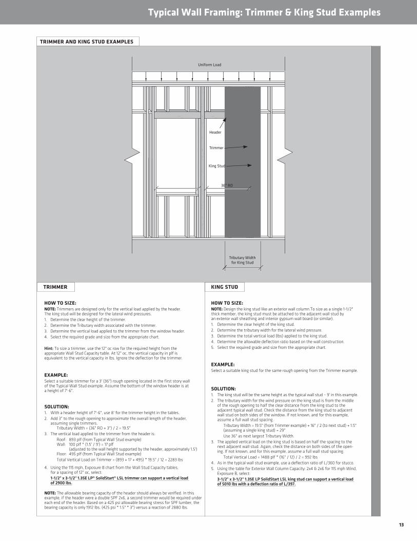
13
KING STUD
Typical Wall Framing: Trimmer & King Stud Examples
TRIMMER AND KING STUD EXAMPLES
Tributary Width for King Stud
Uniform Load
Header
Trimmer
King Stud
36" RO
HOW TO SIZE: NOTE: Trimmers are designed only for the vertical load applied by the header. The king stud will be designed for the lateral wind pressures.1. Determine the clear height of the trimmer.2. Determine the Tributary width associated with the trimmer.3. Determine the vertical load applied to the trimmer from the window header.4. Select the required grade and size from the appropriate chart.
Hint: To size a trimmer, use the 12" oc row for the required height from the appropriate Wall Stud Capacity table. At 12" oc, the vertical capacity in plf is equivalent to the vertical capacity in lbs. Ignore the deflection for the trimmer.
EXAMPLE: Select a suitable trimmer for a 3' (36") rough opening located in the first story wall of the Typical Wall Stud example. Assume the bottom of the window header is at a height of 7'-6".
SOLUTION: 1. With a header height of 7'-6", use 8' for the trimmer height in the tables.2. Add 3" to the rough opening to approximate the overall length of the header,
assuming single trimmers. Tributary Width = (36" RO + 3") / 2 = 19.5"
3. The vertical load applied to the trimmer from the header is: Roof: 893 plf (from Typical Wall Stud example)
Wall: 100 plf * (1.5' / 9') = 17 plf (adjusted to the wall height supported by the header, approximately 1.5') Floor: 495 plf (from Typical Wall Stud example)
Total Vertical Load on Trimmer = (893 + 17 + 495) * 19.5" / 12 = 2283 lbs
4. Using the 115 mph, Exposure B chart from the Wall Stud Capacity tables, for a spacing of 12" oc, select:1-1/2" x 3-1/2" 1.35E LP® SolidStart® LSL trimmer can support a vertical load of 2900 lbs.
NOTE: The allowable bearing capacity of the header should always be verified. In this example, if the header were a double SPF 2x6, a second trimmer would be required under each end of the header. Based on a 425 psi allowable bearing stress for SPF lumber, the bearing capacity is only 1912 lbs. (425 psi * 1.5" * 3") versus a reaction of 2880 lbs.
HOW TO SIZE: NOTE: Design the king stud like an exterior wall column.To size as a single 1-1/2" thick member, the king stud must be attached to the adjacent wall stud by an exterior wall sheathing and interior gypsum wall board (or similar).1. Determine the clear height of the king stud.2. Determine the tributary width for the lateral wind pressure.3. Determine the total vertical load (lbs) applied to the king stud.4. Determine the allowable deflection ratio based on the wall construction.5. Select the required grade and size from the appropriate chart.
EXAMPLE:Select a suitable king stud for the same rough opening from the Trimmer example.
SOLUTION: 1. The king stud will be the same height as the typical wall stud – 9' in this example.2. The tributary width for the wind pressure on the king stud is from the middle
of the rough opening to half the clear distance from the king stud to the adjacent typical wall stud. Check the distance from the king stud to adjacent wall stud on both sides of the window. If not known, and for this example, assume a full wall stud spacing.
Tributary Width = 19.5" (from Trimmer example) + 16" / 2 (to next stud) + 1.5" (assuming a single king stud) = 29"
Use 36" as next largest Tributary Width.3. The applied vertical load on the king stud is based on half the spacing to the
next adjacent wall stud. Again, check the distance on both sides of the open-ing. If not known, and for this example, assume a full wall stud spacing.
Total Vertical Load = 1488 plf * (16" / 12) / 2 = 992 lbs4. As in the typical wall stud example, use a deflection ratio of L/360 for stucco.5. Using the table for Exterior Wall Column Capacity: 2x4 & 2x6 for 115 mph Wind,
Exposure B, select:3-1/2" x 3-1/2" 1.35E LP SolidStart LSL king stud can support a vertical load of 5010 lbs with a deflection ratio of L/397.
TRIMMER

14
Typical Wall Framing: Wall Column Examples
WALL COLUMN EXAMPLE
WINDOW COLUMN EXAMPLE
HOW TO SIZE1. Determine the clear height of the column.2. Determine the tributary width for the lateral wind pressure.3. Determine the total vertical load (lbs) applied to the column.4. Determine the allowable deflection ratio based on the wall construction.5. Select the required grade and size from the appropriate chart.
EXAMPLE:This column sits between two windows, both 36" rough openings, in the wall from the previous example. For this example, there is no additional concentrated load applied. The only vertical loads will be the uniform load from the roof trusses, second story wall and the second floor.
HOW TO SIZE1. Determine the clear height of the column.2. Determine the tributary width for the lateral wind pressure.3. Determine the total vertical load (lbs) applied to the column.4. Determine the allowable deflection ratio based on the wall construction.5. Select the required grade and size from the appropriate chart.
EXAMPLE:Based on the conditions from the typical wall stud example, select a wall column in the same first story wall to support a girder truss load of 4020 lbs. The design must include the weight of the second story wall and the load from the second floor.
SOLUTION:1. The column will be the same height as the typical wall stud - 9' in this example.2. The tributary width for the wind pressure will be the same as that from the typical stud example: 16." Hint: Even if this column falls off-center between two typical studs, the tributary width is still 16" (in this case)
as the total oc distance between the adjacent studs is 32."3. The applied vertical load on the column will be the girder truss load transferred through the second story
wall column, the tributary area of the second floor and the tributary weight of the second story wall (both the same as in the typical wall stud). Roof: 4020 lbs Wall: 100 plf x 16" oc / 12 = 134 lbs Floor: 495 plf x 16" oc / 12 = 660 lbs Total Vertical Load = 4020 + 134 + 660 = 4814 lbs
4. As in the typical wall stud example, use a minimum deflection ratio of L/360 for stucco.5. Using the table for Exterior Wall Columns: 2x4 & 2x6 for 115 mph Wind, Exposure B, select:
3-1/2" x 3-1/2" 1.35E LP SolidStart LSL column can support a vertical load of 5280 lbs with a deflection ratio of L/894.
SOLUTION:1. The column will be the same height as the typical wall stud – 9'.2. The tributary width for the wind pressure will be half the rough opening to both sides
plus the width of the column and the trimmers. Since the width of the column is not known but the only vertical loads are the uniform loads from the common trusses, try a double 1-1/2" x 3-1/2" column. Tributary Width = 2 * (36" / 2) + 2 * 1-1/2" (trimmers) + 2 * 1-1/2" (double 1-1/2" column) = 42"
Use 48" as next largest Tributary Width.3. The applied vertical load on the column will only be the uniform load from the common
roof trusses between the trimmers – assume a typical stud spacing of 16" for simplicity. The trimmers will support the vertical load from the window headers.
Total Vertical Load = 1488 plf (from Typical Wall Stud example) * 16" oc / 12 = 1984 lbs
4. Again, use a deflection ratio of L/360 for stucco.5. Using the table for Exterior Wall Columns: 2x4 & 2x6 for 115 mph Wind,
Exposure B, select:5-1/2" x 3-1/2" 1.35E LP® SolidStart® LSL column can support a vertical load of 8660 lbs with a deflection ratio of L/477.
Wall Column
Concentrated Load
Uniform Load
Tributary Width
Concentrated Load
Wall Column
Uniform Load
36" RO 36" RO
Tributary Width for Column

15
Free-Standing Interior Column Capacity (lbs)
TO USE:1. Determine the height of the column. If not listed, select the next tallest Height in the table.2. Select the row corresponding to the required load duration.3. Select the LP® SolidStart® LSL or LVL grade and size where the Vertical Load Capacity meets or exceeds the applied vertical load.4. Verify the bearing capacity of the support for the selected column. See Design Assumption 6 below.
ADDITIONAL NOTES:1. The value in each cell represents the allowable vertical load capacity of
a column, in pounds (lbs).2. The column dimensions are for one-piece members. Built-up columns
are beyond the scope of this table.3. Do not use a product where designated “-” without further analysis
by a professional engineer.4. For columns embedded in interior walls where drilling or notching may
be required, use the Exterior Wall Column Capacity tables for 115 mph, Exposure B, for the appropriate wall thickness (2x4, 2x6, 2x8 or 2x10). This will conservatively account for the required 5 psf lateral wall load.
DESIGN ASSUMPTIONS:1. Column Height is the clear height of the column between top and bottom supports.2. The vertical load capacity is the total vertical load applied to the column, including all dead loads.
No lateral loads have been applied.3. The vertical capacity is for a full cross-section only. Notching and drilling are not allowed without
further analysis by a professional engineer except as required for the proper installation of column caps, bases and other hold-downs. Bolts, lag screws and self-tapping screws shall only be inserted through the face of the column, perpendicular to the face of the strands in LP LSL and the veneers in LP LVL.
4. The capacity assumes an eccentricity of 1/6 of the column depth or width, whichever controls.5. Interior columns are assumed to be braced in both directions at the top and bottom supports.6. The tabulated capacities have been limited by the bearing capacity of 2500 psi concrete. For bearing
on a lower strength concrete or a wood plate, the designer shall check the required vertical load against the bearing capacity for the plate and increase the column size accordingly. Refer to the Bearing Capacity table on page 4 for column bearing on LP SolidStart LSL and LP LVL, or for the common species of Hem-Fir and SPF. No increase is allowed without complete analysis of the vertical capacity of the column.
Height Load Duration
1.35E LP LSL 1.55E LP LSL or 1.5E LP LVL3-1/2" x 3-1/2" 3-1/2" x 5-1/2" 3-1/2" x 7-1/4" 3-1/2" x 9-1/4" 3-1/2" x 3-1/2" 3-1/2" x 5-1/2" 3-1/2" x 7-1/4" 3-1/2" x 9-1/4"
4'100% 10410 16360 21560 27510 10410 16360 21560 27510115% 10410 16360 21560 27510 10410 16360 21560 27510125% 10410 16360 21560 27510 10410 16360 21560 27510
6'100% 7600 11950 15760 20100 8330 13100 17260 22030115% 8070 12680 16720 21340 8770 13790 18170 23190125% 8340 13110 17280 22050 9030 14190 18710 23870
8'100% 5280 8300 10940 13960 5650 8870 11700 14930115% 5500 8640 11390 14540 5860 9200 12140 15480125% 5620 8840 11650 14870 5980 9400 12390 15810
9'100% 4460 7000 9230 11780 4740 7450 9820 12530115% 4610 7250 9560 12200 4890 7690 10130 12930125% 4710 7400 9750 12440 4980 7820 10320 13160
10'100% 3800 5970 7870 10050 4020 6320 8330 10630115% 3920 6160 8120 10360 4140 6500 8570 10940125% 3990 6270 8260 10540 4200 6610 8710 11120
12'100% 2840 4470 5900 7530 2990 4710 6210 7920115% 2920 4590 6050 7720 3060 4820 6350 8100125% 2960 4650 6130 7820 3100 4880 6430 8210
14'100% 2200 3460 4570 5830 2310 3630 4790 6110115% 2250 3540 4660 5950 2350 3700 4880 6230125% 2280 3580 4720 6020 2380 3740 4940 6300
Height Load Duration
2.0E LP LVL3-1/2" x 3-1/2" 3-1/2" x 5-1/2" 3-1/2" x 7-1/4" 3-1/2" x 9-1/4" 5-1/4" x 5-1/2" 5-1/4" x 7-1/4" 5-1/4" x 9-1/4" 7" x 7-1/4" 7" x 9-1/4"
4'100% 10410 16360 21560 27510 24540 32350 40000 40000 40000115% 10410 16360 21560 27510 24540 32350 40000 40000 40000125% 10410 16360 21560 27510 24540 32350 40000 40000 40000
6'100% 10410 16360 21560 27510 24540 32350 40000 40000 40000115% 10410 16360 21560 27510 24540 32350 40000 40000 40000125% 10410 16360 21560 27510 24540 32350 40000 40000 40000
8'100% 7930 12460 16430 20960 24540 32350 40000 40000 40000115% 8230 12940 17060 21770 24540 32350 40000 40000 40000125% 8410 13220 17430 22230 24540 32350 40000 40000 40000
9'100% 6660 10480 13810 17620 24540 32350 40000 40000 40000115% 6890 10830 14270 18210 24540 32350 40000 40000 40000125% 7020 11030 14540 18560 24540 32350 40000 40000 40000
10'100% 5670 8910 11750 14990 24010 31650 40000 40000 40000115% 5840 9180 12100 15440 24540 32350 40000 40000 40000125% 5940 9330 12300 15700 24540 32350 40000 40000 40000
12'100% 4230 6650 8770 11190 18690 24640 31440 40000 40000115% 4330 6810 8980 11460 19410 25590 32650 40000 40000125% 4390 6910 9110 11620 19830 26140 33350 40000 40000
14'100% 3270 5140 6780 8650 14870 19610 25020 39570 40000115% 3340 5250 6920 8830 15350 20240 25830 40000 40000125% 3380 5310 7000 8930 15630 20600 26290 40000 40000
16'100% - - - - 12080 15920 20310 32860 40000115% - - - - 12410 16360 20870 34130 40000125% - - - - 12600 16620 21200 34860 40000
18'100% - - - - 9980 13160 16790 27630 35250115% - - - - 10220 13480 17200 28550 36430125% - - - - 10360 13660 17430 29090 37120
20'100% - - - - 8370 11040 14090 23500 29990115% - - - - 8560 11280 14400 24210 30890125% - - - - 8660 11420 14570 24610 31400
22'100% - - - - - - - 20210 25780115% - - - - - - - 20750 26480125% - - - - - - - 21060 26870
24'100% - - - - - - - 17540 22380115% - - - - - - - 17970 22930125% - - - - - - - 18220 23240
26'100% - - - - - - - 15360 19600115% - - - - - - - 15710 20040125% - - - - - - - 15900 20290
28'100% - - - - - - - 13560 17300115% - - - - - - - 13840 17660125% - - - - - - - 14000 17860

16
Nailing and Connection Details
WALL SHEATHING PANEL EDGE NAILINGNOTES:1. Minimum LP® SolidStart® LSL or LVL thickness for a single
stud is 1-1/2."2. A double stud (or a minimum 2-1/2" single stud) are required
at adjoining panel edges as follows: a. For LP SolidStart LSL when using 8d common nails spaced closer than 4" oc or 10d common nails spaced closer than 6" oc.
b. For LP SolidStart LVL when using 8d common nails spaced closer than 6" oc. 10d common nails are not allowed for a single stud.
3. The panel-edge nailing at a double stud shall be installed a minimum 1/2" from both the panel edge and the edge of the stud, and shall be installed with every other nail staggered a minimum 1/4" horizontally.
4. The minimum nail spacing into the edge of the stud shall not be less than: a. For LP SolidStart LSL: 3" oc for both 8d and 10d common nails.
b. For LP SolidStart LVL: 3" oc for 8d common nails or 4" oc for 10d common nails.
5. Do not use nails larger than 10d common nails for wall sheathing nailing.
6. In lieu of engineering analysis for prescriptive wall framing, the double studs shall be stitch-nailed together with 2 staggered rows of 10d common nails spaced 8" oc in each row. For engineered walls, the stitch nailing shall be designed to transfer the required lateral shear.
SINGLE STUD AT ADJOINING PANELS
DOUBLE STUD AT ADJOINING PANELS

17
FASTENER & LOAD ORIENTATION
Nailing and Connection Details
FASTENER DESIGN
Material
Equivalent Specific GravityNails and Wood Screws Bolts and Lag Screws
Withdrawal Dowel Bearing Dowel Bearing (into the face only)Edge Face Edge Face Load Applied Parallel to Grain Load Applied Perpendicular to Grain
LP SolidStart LSL 0 .46 0 .50 0 .50 0 .55 0 .50 0 .58LP SolidStart LVL 0 .46 0 .50 0 .50 0 .50 0 .46 0 .50
NAIL SPACING REQUIREMENTS
Material Ply Thickness
Fastener Orientation
Nail Size (common or box)
Minimum End Distance
Minimum Nail Spacing per Row
Single Row Multiple Rows
LP SolidStart LSL ≥ 1-1/2"
Edge8d 2" 3" 3"
10d or 12d 2" 3" 4"16d 2-1/2" 4"5 6"
Face8d 7/8" 1" 1"
10d or 12d 7/8" 1" 1"16d 7/8" 1-1/2" 1-1/2"
LP SolidStart LVL ≥ 1-1/2"
Edge8d 2-1/2" 3" 4"6
10d or 12d 2-1/2" 4" 5"6
16d 3-1/2" 5" 6"7
Face8d 1-1/2" 3" 3"
10d or 12d 1-1/2" 3" 3"16d 1-1/2" 5" 5"
NOTES:1. Connection design using the equivalent specific gravity for each connection type listed above is for normal load duration and shall be adjusted according to code.2. Fastener spacing, end and edge distance shall be as specified by code except for nail spacing as specified below.3. See details at right for fastener and applied load orientation.
NOTES:1. Edge distance shall be such that does not cause splitting.2. Multiple rows of nails shall be offset at least 1/2" and staggered, and equally spaced about the centerline of the edge or face (whichever applies).3. Edge orientation refers to nails driven into the narrow edge: parallel to the face of the strands for LP LSL or the face of the veneer for LP LVL.
Face orientation refers to nails driven into the wide face: perpendicular to the face of the strands for LP LSL or the face of the veneer for LP LVL. (See Fastener & Load Orientation details at right.)
4. 16d sinkers (3-1/4" x 0.148") may be spaced the same as the 10d or 12d common nail.5. Single row spacing for 16d nails into the edge can be reduced to 3" for 1-3/4" or thicker LSL.6. Minimum nail spacing is tabulated for LVL manufactured from the Sutherlin plant (Mill number 1089). The minimum nail spacing may
be reduced by 1 inch for LVL manufactured from the Wilmington and Golden plants (Mill numbers 1077 and 1066).7. Minimum nail spacing may be reduced by 1 inch for 1-3/4-inch thick (or greater) LVL manufactured from the Sutherlin plant
(Mill number 1089).
Nail into edge
Nail into face
Load applied parallel to grain
Load applied perpendicular to grain

18
Typical Connections
CONNECTION OF BUILT-UP COLUMNS
NAILED PLATE CONNECTIONS
Nail Type Length DiameterLateral Capacity (lbs)
Toe-Nail (lbs) End-Nail8d box 2-1/2" 0 .113" 95 68
8d common 2-1/2" 0 .131" 128 7910d box 3" 0 .128" 123 99
10 common 3" 0 .148" 156 12616d sinker 3-1/4" 0 .148" 156 126
16d box 3-1/2" 0 .135" 136 11016d common 3-1/2" 0 .162" 187 151
NOTE: 1. The lateral capacity assumes a load duration adjustment
for wind, Cd = 1.60.2. Connections assume an equivalent specific gravity
of 0.50 for both the side member and main member. For an SPF plate (SG=0.42), multiply the tabulated lateral capacities by 0.84. For a Hem-Fir plate (SG=0.46), multiply the tabulated capacities by 0.93.
3. Toe-nail connections assume a toe-nail adjustment factor, Ctn = 0.83 for lateral capacity.
4. End-nail connections assume an end grain adjustment factor, Ceg = 0.67 for lateral capacity.
TYPICAL FRAMING ANCHORS
Anchor Type Number of NailsCapacity (lbs)
Force 1 Force 2Simpson Strong-Tie®
A21 (4) 10d x 1-1/2" 175 245A23 (8) 10d x 1-1/2" 565 585A34 (8) 8d x 1-1/2" 365 280A35 (12) 8d x 1-1/2" 450 685
USP Structural Connectors®A3 (8) 10d x 1-1/2" 590 600
AC3 (4) 10d 280 315AC5 (6) 10d 545 545AC7 (8) 10d 725 725AC9 (10) 10d 910 900
NOTE: 1. Refer to the manufacturers’ current catalogs
for complete information.2. Capacities assume both members being equivalent
to Doug Fir-Larch or Southern Pine, with an equivalent specific gravity of 0.50 or better.
3. Capacities are for a load duration adjustment for wind, Cd = 1.60.
4. Capacities are for a single anchor and may be doubled when installed in pairs.
TYPICAL CONNECTIONS
BEAM ON COLUMN CAP
ELEVATED COLUMN BASE
Optional non-shrink
grout
1-1/4" LSL or LVL or 1-1/8" rim board or blocking
for lateral support
Column
EXAMPLES OF FRAMING ANCHORS
BEAM ON COLUMN
COLUMN BASE
2-1/
4"
6"
1"
1"
6"
2-1/
4"6"
1"
1"
2-1/
4"
1"
1"
4"4"
1"1"
1"1"1"
1"
1"
1"
2-1/
4"
1"
1"
6"6"
Force 1
Force 2
Framing Anchors
Toe-Nail
End-Nail
Framing anchor as required for lateral load
Use trimmers as required
Built-up columns shall be designed in accordance with the 2012 NDS using the following recommended nailing and bolt patterns.
2-Ply 1-1/2" x 3-1/2" • One row of 10d box nails (3" x 0.128")
spaced 6" oc.• Drive every other nail from opposite
faces and offset horizontally.
3-Ply 1-1/2" x 3-1/2"• One row of 10d box nails spaced 4" oc
from both faces.• Horizontally offset every other nail
in the row.• Stagger rows on each face and from
front to back.
2-Ply 1-1/2" x 5-1/2" and wider• Two rows of 10d box nails
spaced 6" oc.• Drive every other nail in a row
from opposite faces.• Stagger rows.
3-Ply 1-1/2" x 5-1/2" and wider• Three rows of 10d box nails
spaced 6" oc from both faces.• Stagger rows on each face and
from front to back.
4-Ply 1-1/2" x 5-1/2" and wider (not shown)• Two rows of 1/2" bolts spaced 8" oc.• Maintain a 2" minimum edge distance and 4"
minimum end distance.
2-1/
4"
6"
1"
1"
6"
2-1/
4"6"
1"
1"
2-1/
4"
1"
1"
4"4"
1"1"
1"1"1"
1"
1"
1"
2-1/
4"
1"
1"
6"6"
2-1/
4"6"
1"
1"
6"
2-1/
4"
6"1"
1"
2-1/
4"
1"
1"
4"4"
1"1"
1"1"1"
1"
1"
1"
2-1/
4"
1"
1"
6"6"
2-1/
4"6"
1"
1"
6"
2-1/
4"
6"
1"
1"
2-1/
4"
1"
1"
4"4"
1"1"
1"1"1"
1"
1"
1"
2-1/
4"
1"
1"
6"6"
NOTES:1. Larger nails may be used. Do not exceed a 16d common nail.2. Except as specified herein, nail spacing, row spacing, edge distance and end distance
shall be in accordance with the NDS.3. Do not exceed three plies for 1-1/2" x 3-1/2" wide members.

19
• Warning: Failure to follow proper procedures for han-dling, storage and installation could result in unsatis-factory performance, unsafe structures and possible collapse .
• Keep LP® SolidStart® LSL and LVL dry . These prod-ucts are intended to resist the effects of moisture on structural performance from normal construction delays but are not intended for permanent exposure to the weather .
• Unload products carefully, by lifting . Support the bundles to reduce excessive bowing . Individual products should be handled in a manner which prevents physical damage during measuring, cutting, erection, etc .
• Keep products stored in wrapped and strapped bundles, stacked no more than 10' high . Support and separate bundles with 2 x 4 (or larger) stickers spaced no more than 10' apart . Keep stickers in line vertically .
Handling and Storage Guidelines
• Product must not be stored in contact with the ground, or have prolonged exposure to the weather .
• Use forklifts and cranes carefully to avoid damaging product .
• Do not use a visually damaged product . Call your local LP SolidStart Engineered Wood Products distributor for assistance when damaged products are encountered .
• For satisfactory performance, LP SolidStart LSL and LVL must be used under dry, covered and well-ventilat-ed interior conditions in which the equivalent moisture content in lumber will not exceed 16% .
• For built-up members, LP SolidStart LSL and LVL shall be dry before nailing or bolting to avoid trapping mois-ture .
• LP SolidStart LSL and LVL shall not be used for unin-tended purposes such as ramps and planks .

© 2014 Louisiana-Pacific Corporation. All rights reserved. APA and APA Rated are registered trademarks of APA – The Engineered Wood Association. SIMPSON STRONG-TIE is a registered trademark of Simpson Strong-Tie Company, Inc. SFI and the associated logo are trademarks of Sustainable Forestry Initiative, Inc. PEFC and the associated logo are trademarks of Programme for the Endorsement of Forest Certification. USP STRUCTURAL CONNECTORS is a registered trademark of United Steel Products Company. LP and SolidStart are registered trademarks of Louisiana-Pacific Corporation. Printed in USA. Specifications (details) subject to change without notice.
LPEW0346 12/15 0M OS/Argent
For more information on the full line of LP® SolidStart® Engineered Wood Products or the nearest distributor, visit our web site at LPCorp.com.
LP SolidStart Engineered Wood Products are manufactured at different locations in the United States and Canada. Please verify availability with the LP SolidStart Engineered Wood Products distributor in your area before specifying these products.
PEFC/29-31-102 BV-SFICOC-US09000262
Cal. Prop 65 Warning: Use of this product may result in exposure to wood dust, known to the State of California to cause cancer.
Phone: 1-888-820-0325E-mail: [email protected].