lpefi® general diagnostic manual - bi-phase · general diagnostic manual. revision ... may not be...
TRANSCRIPT

LPEFI® Liquid Propane Electronic Fuel Injection
General Diagnostic Manual
Revision 10 February, 2014
Manual # M4-121-10 Bi-Phase Technologies, LLC
Eagan, Minnesota, U.S.A.

This manual is for general diagnosis that applies to any LPEFI system installed on any vehicle. Where there is a difference in components or installation, it will be identified by specific vehicle. The theory and diagnostics for the system are the same for any vehicle that the system might be installed on. However, the system is calibrated to a specific vehicle and some components, specifically injectors, cannot be interchanged. In this manual you will find different approaches to diagnostics and troubleshooting. We will reference specific OEM repair manuals where a technician may need to obtain the OEM manual to complete the diagnostics. In many cases, the propane injection system may not be the fault and further investigation of the engine control system may be required. Remember the basics when troubleshooting. To prevent the replacement of good components it is necessary to have a general knowledge of both the LPEFI system and the vehicle.
“Read all instructions before use to avoid injury”
Anyone who performs repairs to the LPEFI system must be trained and certified. This is a propane system and anyone who performs repairs must have knowledge of Liquefied Petroleum Gases and understand safe handling and characteristics of such. Some states may require a license to work on propane vehicles. Consult your state or local authorities or your state propane gas association. Bi-Phase Technologies is not responsible for your oversight to comply with federal, state or local laws regulating the installation or repair of propane gas systems.
The LPEFI system is a sequential multi-port fuel injection system that injects propane in a liquid state to the engine. It works the same way as a modern sequential multi-port gasoline fuel injection system and can be diagnosed with the same diagnostic scanners used for gasoline vehicles. The LPEFI system is covered by U.S. and International patents. The LPEFI system is also certified to the United States E.P.A. standards. The information in this manual is believed to be accurate as of its date of publication but it is subject to change. Up-to-date information and changes, if any, can be requested from Bi-Phase Technologies. In the event of any safety-related changes, Bi-Phase Technologies will notify all customers who returned the warranty registration card for the affected vehicles. For more information contact: Bi-Phase Technologies, LLC
2945 Lone Oak Drive, Suite 150 Eagan, MN 55121 (952) 886-6450 (888) 465-0571 Tech. Support Line

Propane Safety Warnings ......................................................................................................................... 1
Theory of Operation ................................................................................................................................ 6
LPEFI Purge Logic ..................................................................................................................................... 9
Idle Shut Down ...................................................................................................................................... 12
LPEFI Diagnostic Equipment ................................................................................................................... 14
Basic Diagnostics .................................................................................................................................... 20
Diagnostics............................................................................................................................................. 25
Transfer System ......................................................................................................................................... 48
Service Procedures ................................................................................................................................. 51
Draining the Fuel Lines .............................................................................................................................. 51
Fuel Rail Removal ...................................................................................................................................... 53
Fuel Line Removal ..................................................................................................................................... 55
The “WYE” ................................................................................................................................................. 57
Installing Fuel Lines ................................................................................................................................... 59
Injectors/Rails............................................................................................................................................ 65
LPDM ......................................................................................................................................................... 69
YLPDM ....................................................................................................................................................... 70
Auxiliary LPDM .......................................................................................................................................... 71
Scavenge Pump ......................................................................................................................................... 75
Fuel Pump ................................................................................................................................................. 80
Purging a Tank ........................................................................................................................................... 81
Purging the Transfer System ..................................................................................................................... 83
Drain/Evacuate a Tank .............................................................................................................................. 84
Preventative Maintenance ..................................................................................................................... 89
Leak Checking the System ......................................................................................................................... 93
Tank Valves .......................................................................................................................................... 100
Specifications ....................................................................................................................................... 104
Spark Plugs/Sending Units ...................................................................................................................... 104
Calibration Codes .................................................................................................................................... 105
LPCM ....................................................................................................................................................... 106
Wire Harness’s ........................................................................................................................................ 110
Tank/Hose Schematic .............................................................................................................................. 127
Contact Information ............................................................................................................................. 139
TABLE OF CONTENTS

Bi-Phase Technologies, LLC
Page left blank for notes

Bi-Phase Technologies LPEFI
PROPANE SAFETY
1
This is a safety alert symbol. It is used throughout this manual to alert you to potential hazards. Whenever you see this symbol, you should read and obey the safety warnings that follow. Failure to obey these warnings could result in serious personal injury or property damage.
Warning: Never loosen fitting’s or vent any propane. Escaping propane can cause frostbite and severe freeze burns. Wear insulated PVC rubber gloves resistant to propane, goggles for protection against accidental release of pressurized products, and thermal protective clothing when handling refrigerated liquids.
Propane is stored as a liquid. When you release liquid propane, it tries to evaporate as quickly as it can, by absorbing heat from its surroundings. Everything it touches gets chilled to -44 degrees F (-42 degrees C). If liquid propane sprays on your skin, it will freeze it. Anyone who works with liquid propane must wear PVC insulated rubber gloves.
Danger: Do not remove any valves, bulkheads, or fitting’s from a tank unless the tank has been drained completely. The pressure inside a propane tank can push a loosened bulkhead or valve out with enough force to cause injury or death.
Propane is stored under pressure. When you remove a valve or bulkhead from the tank, all of the pressure is released at once in a violent rush. Always drain the tank before you work on it. Failure to do this will result in damage to the tank or valves and can result in severe injury or death. You should drain the tank by the fuel transfer method and/or by using a flare stack in an approved safe manner. Your propane supplier can help you with this.
_______________________________________________________________________ _______________________________________________________________________

Bi-Phase Technologies LPEFI
PROPANE SAFETY
2
Warning: Keep all sources of ignition away from propane vehicles while the fuel system is being serviced. Even if the tank and fuel lines are empty, there may still be flammable vapors near the vehicle.
Do not allow smoking, sparks, flames, recent or running vehicles or other sources of ignition when fueling, servicing and vented propane. Failure to do this could result in fire or explosion, causing severe property damage, injury or death. _______________________________________________________________________
Warning: Do not disconnect any propane hoses unless they have been properly drained completely.
Propane in the hoses is kept under pressure, even when the engine is off. When you disconnect a hose; the internal pressure is released all at once. Always drain the fuel lines before you disconnect them. Failure to do this can result in damage to the hose fitting and possible injury. See repair procedures in this manual for instructions.
________________________________________________________________ _______
Danger: Do not vent or release propane indoors or near sewers, pits or low lying areas. Propane can accumulate in low spots, creating a fire hazard. Propane can also displace oxygen, creating a suffocation hazard.
Propane is heavier than air. It can fill low, sheltered areas with flammable vapors. If these vapors are ignited, they can create a fire or explosion, causing severe property damage, injury or death. Never release propane near sewers, pits or indoors.
_______________________________________________________________________

Bi-Phase Technologies LPEFI
PROPANE SAFETY
3
Propane gas is the most widely used alternative fuel, with nearly 4 million vehicles worldwide running on propane. More than 350,000 vehicles run on propane in the U.S. according to the U.S. Department of Energy’s Alternative Fuels Data Center. Propane powered vehicles offer the best combination of durability, performance and driving range. The first propane powered vehicle ran in 1913. Bi-Phase Technologies’ LPEFI (Liquid Propane Electronic Fuel Injection) system has surpassed other technologies today by introducing liquid fuel injection. This technology improves power, efficiency and operating characteristics. For more information, call for our General Information and Training Manual. Safety comes first is a motto you should always live by. Without knowledge of a product, it is hard to follow this motto. In our manuals we try to stress the need for knowledge and provide warning signs to alert you. It is your responsibility to know the law. National Fire Protection Association (NFPA) has manuals to help you understand safe handling of many products. We recommend that you obtain and read their NFPA #58, Standard for the Storage and Handling of Liquefied Petroleum Gases. A number of training programs and efforts have been implemented throughout the country. The National Propane Gas Association has developed a Certified Employee Training Program (CETP), which provides service personnel with a complete technical training curriculum. We encourage you to contact your state propane gas association or the National Propane Gas Association for more information on how you can benefit from such programs. Visit www.propanesafety.com or www.npga.org for more information.
(Commercial Propane)

Bi-Phase Technologies LPEFI
PROPANE SAFETY
4
C3H8
Specific gravity of liquid (water = 1) at 60 degrees F. 0.504 Initial boiling point at 14.7 psia, in degrees F. - 44.0 Weight in pounds per gallon of liquid at 60 degrees F. 4.24 Cubic ft. of vapor per gallon at 60 degrees F. 36.38 Cubic ft. of vapor per pound at 60 degrees F. 8.66 Specific gravity of vapor (air = 1) at 60 degrees F. 1.50 Ignition temperature in air, in degrees F. 920 to 1120 Maximum flame temperature in air, in degrees F. 3,595 Limits of flammability in air Percent of vapor in air/gas mixture
Lower 2.15 Upper 9.60
Air/Fuel ratio by volume 15.6:1 Air/Fuel ratio by weight 24:1 Octane number as it relates to gasoline 98 to 102 Heating values
BTU per cubic foot 2,488 BTU per pound 21,548 BTU per gallon 91,500
Chemical formula C3H8 Vapor pressure in psig
70 degrees F 127 100 degrees F 196 105 degrees F 210
Bi-Phase Technologies LPEFI
PROPANE SAFETY
5
Definitions
The following index will help define various acronyms discussed throughout the General Diagnosis Manual. KOEO – Key On Engine Off
KOER – Key ON Engine Running
LPEFI – Liquid Propane Electronic Fuel Injection
YLPDM – Wye Liquid Propane Delivery Module
LPCM – Liquid Propane Control Module
ISD – Idle Shut Down
QD – Quick Disconnect
WTS – Wait to Start
Idle Shut down (ISD) – the LPCM will shut off an idling truck in 1, 3 or 15 minutes. There are two modes of ISD; Warm-up and Normal. ISD will not occur if the truck is any drive position
Warm-Up- 15 minute ISD when vehicle has been shut off for >30min and not taken out of the Park/Neutral position. Disconnecting 12V to LPCM will reset LPCM and put ISD into Warm-Up mode
Normal- 1-3 minute ISD when vehicle has been off for <30 minutes and taken out of the Park/Neutral position; then placed back into Park/Neutral
Liquid Propane Control Module (LPCM) – The LPCM is the “green/black/red/blue aluminum box” on the tank cover on the end of the primary tank. Has the logic to run the LPDM, ISD, Auto Purge, and Anti Tampering programs.
Liquid Propane Control Module (CINCH LPCM) – The CINCH LPCM is the black polymer box on the tank cover on the end of the primary tank. It has the logic to run the LPDM, ISD, Auto Purge, Fuel Transfer, Fuel Level Output, and Anti Tampering programs. Replacement for the LPCM (2012)
Liquid Propane Delivery Module (LPDM) – Red or brass bulk head on the end of the primary tank. Contains two solenoid valves which control fuel supply and return to the engine
Secondary Liquid Propane Delivery Module (LPDM) – Blue or Brass bulk head on the end of the Secondary tank. Only used for transferring fuel from the secondary tank(s) to the primary tank. Contains 1 solenoid wired in parallel with the transfer pump
Purge Cycle – Pump runs in the tank with the supply and return valve open to circulate liquid propane to the engine to ensure there is no air in the system for easier start ups

Bi-Phase Technologies LPEFI
THEORY AND OPERATION
6
Introduction This article covers basic description and operation of the LPEFI system. Read this information before diagnosing vehicles or systems with which you are not completely familiar. The LPEFI System The LPEFI system is a direct replacement propane fuel injection system. It replaces the gasoline fuel injection system and works the same as a gasoline fuel injection system with the exception it injects propane (in a liquid state) into the intake port. The gasoline system electronic engine management stays the same and controls the LPEFI system just as it did the gasoline injection system. Onboard diagnostics remain unchanged so the same scan tool and diagnostic approach remains equal to a gasoline system. The only change in electronic engine management is the fuel enrichment strategy on start up. Gasoline needs a very rich fuel mixture to start the engine and differs greatly based on outside ambient temperatures. With propane this fuel enrichment requirement is much less, thus reducing the level of startup emissions compared with gasoline. The LPEFI system accomplishes this start up fuel enrichment strategy change in one of three ways:
1. The PCM is recalibrated for a propane 2. An additional engine coolant temperature sensor is installed and piggybacks the OEM sensor, or 3. A new replacement engine coolant temperature or cylinder head temperature sensor is installed.
It is important that you know how to recognize this change as changing a PCM or engine coolant temperature sensor could cause problems if not replaced with the correct part. With exception of Ford of Mexico original factory equipped LPEFI vehicles, model years 2003 use an additional engine coolant temperature sensor piggybacked to the OEM sensor or a replacement coolant temperature or cylinder head temperature sensor. All 1999 thru 2002 GMC medium duty trucks use a programmed PCM which show a cold engine temperature at approximately at 140 degrees. 2004 - 2013 model years also use a programmed PCM but without any changes to normal vehicle operation. Some 2009 Isuzu model W4500 trucks have replacement coolant temperature or cylinder head temperature sensor. A label is usually placed near the OBD II connector in the cab if the PCM has been re-flashed. Calibration codes can also be detected to identify a PCM re-flash via a scan tool. Specific vehicle calibration codes can be found in the Specifications section in this manual. The LPEFI system consists of three main components: the tank, the fuel lines and the injectors. The tank location varies per vehicle make/model. The fuel lines are routed forward to the engine compartment where the injector rail assemblies are mounted in the same position as the original gasoline injector rails. The LPEFI fuel lines use a concentric design where the supply line is inside the return line. There are no EVAP canisters in the LPEFI system. The Tank (ASME design, 312.5 p.s.i. working/design pressure) The fuel tank includes an internal electric fuel pump & filter, condenser (condenser eliminated beginning with 2005 models), fuel supply & return valves, baffle keeps the pump submerged in liquid propane, scavenge pump (if applicable), fuel level float assembly, pressure relief valve, overfill prevention device(s), and liquid and vapor service valves. LPEFI vehicles may have one or two tanks. If it is fitted with two tanks, a primary tank, which controls all fuel delivery to the injectors; and a secondary tank which only transfers fuel to the primary fuel tank based on fuel level inputs to a transfer module, OEM PCM, or LPCM module. The main fuel tank fuel pump increases or boosts the tank pressure by 45 to 65 psi. No matter what the propane tank internal pressure is, the pump boost remains the same. This is how the propane stays a liquid throughout the liquid supply section of the system. The fuel is supplied to the injectors and whether the injector is open or not fuel passes through a cooling bushing in the injector and is returned to the tank. This is called a refrigeration cycle and also aids in maintaining the fuel in a liquid state throughout the supply passageways in the system. Because propane easily vaporizes, when the refrigeration cycle stops (when the engine is turned off) or if the return valve malfunctions closed, the propane will vaporize and cause a loss in power or hard hot restarting. To help in hot restarting, the system goes through a purge cycle and / or Auto purge feature for 6 to 15 seconds before every start up attempt. This strategy is built into the system’s LPCM. See more about hot restart/hot soak in this manual.

Bi-Phase Technologies LPEFI
THEORY AND OPERATION
7
The Fuel Lines The fuel lines consist of two flexible hoses, one inside the other, in a concentric arrangement. The nylon inner line supplies liquid propane to the injectors while the area between the outside of the inner line and the larger outer hose is the fuel return passage. The concentric fuel line design has a number of benefits:
1. Cuts the number of possible leak points in half, 2. Reduces vapor-lock in the supply line by using the return fuel passage as insulation, 3. Postpones the vapor-lock that occurs after a hot engine is shut off, 4. Shortens the purge cycle time needed to restart a hot engine.
The Injectors The LPEFI system injectors are designed specifically for liquid propane. They mimic the gasoline fuel injectors that they replace. The injector electrical circuit resistance value is 13-15, similar to a gasoline injector. Each fuel injector has a supply passage and a return passage. The fuel injector rails have the same concentric design as the fuel lines. The passage in the injector from the supply section to the return section is restricted by a cooling bushing. As liquid propane passes through the cooling bushing, a pressure reduction takes place, which causes the propane to vaporize and effectively cools the area around the supply section. This is called a refrigeration cycle and aids in maintaining the fuel in a liquid state for all driving conditions, regardless of the outside temperature. The injector delivers propane in a liquid state into the intake port. It vaporizes immediately upon exiting the injector. This rapidly expanding liquid cools the incoming air to the engine often resulting in a little more horsepower than the gasoline system could achieve, not to mention the inherently improved exhaust emissions that propane is known for.

Bi-Phase Technologies LPEFI
THEORY AND OPERATION
8
2002-2004 model years
2009-2010 model years (GM) 2005-2014 model years (Ford, Isuzu)
2012-2014 GM model years

Bi-Phase Technologies LPEFI
LPEFI PURGE LOGIC
9

Bi-Phase Technologies LPEFI
LPEFI PURGE LOGIC
10
LPEFI® Purge Logic
Bi-Phase Technologies LPEFI LPEFI Purge Logic

Bi-Phase Technologies LPEFI
LPEFI PURGE LOGIC
11
WAIT TO START LIGHT (WTS)
Some vehicle models are equipped with a “wait to start” indication lamp installed onto the dashboard to let the driver know the LPG system is in a purge cycle. If equipped the operator should follow the instructions below to properly start the vehicle.
2012-2014 GM SAVANNA
Wait to Start light Instructions
1. Turn the vehicle ignition key to the Key On Engine Off position. Lamp should illuminate indicating a purge cycle is in progress
A. lamp illumination times will vary between 6-12seconds depending on system application.
2. When the light turns off it has indicated the purge cycle is complete and you may now crank the engine

Bi-Phase Technologies LPEFI
IDLE SHUT DOWN (ISD)
12
Idle Shutdown Functions Classic LPCM
Classic LPCM Control Box
Idle Shut Down Modes
Normal - ISD after 3 minutes of idle, the engine will shut off If the truck has been running in the <30 minutes or if the truck has been moved (meaning if the drive selector is moved from the Park position)
Warm up - ISD after 15 minutes of idle, the engine will shut off If the truck has been shut off for >30 minutes it will go into this ISD mode
This will allow for morning warm ups (Defrost windshield, etc) Moving the gear select from the Park position will change the idle shut down mode to Normal ISD mode when the truck is placed back into Park
Auto Purge Quicker engine start ups in hot weather Auto purge will run the pump after the truck is shut off (either by key or ISD) at 1.5 minutes – 3 minutes – 6 minutes – 12 minutes and one last time in 24 minutes Auto Purge is disabled below 50 degrees
Tampering Mode ANY tampering with the ISD components will shut off the fuel pump on the propane tank; the engine will shut off and will result in a 3 minute reset process. The truck will not start within these 3 minutes. Tampering may include items like trying to remove components from the idle shutdown system, opening the truck door with the truck in drive, or having the truck in drive with the parking brake on
Other notes The ISD will not turn off any lights, fan motor, etc A weak battery may be more evident with the ISD installed
IMPORTANT: If the LPCM is replaced, it must be replaced with the same part number as the original box or the truck may experience “Tampering Mode”.

Bi-Phase Technologies LPEFI
IDLE SHUT DOWN (ISD)
13
Idle Shutdown Functions
Cinch LPCM
GM SAVANNA/EXPRESS (2012-2014) COMMON APPLICAION (INSIDE FRAME RAIL, FRONT OF PRIMARY TANK) (BOLTED ONTO END OF FUEL TANK)
2013 Cinch LPCM Control box
Idle Shut Down Modes Normal - ISD after 1 minutes of idle, the engine will shut off
If the truck has been running in the <30 minutes or if the truck has been moved (meaning if the drive selector is moved from the Park position)
Warm up - ISD after 15 minutes of idle, the engine will shut off If the truck has been shut off for >30 minutes it will go into this ISD mode
This will allow for morning warm ups (Defrost windshield, etc) Moving the gear select from the Park position will change the idle shut down mode to Normal ISD mode when the truck is placed back into Park
Auto Purge (If applicable) Quicker engine start ups in warm weather Auto purge will run the pump after the truck is shut off (either by key or ISD) at 1.5 minutes – 3 minutes – 6 minutes – 12 minutes and one last time in 24 minutes Auto Purge is disabled below 50 degrees.
Tampering Mode ANY tampering with the ISD components will shut off the fuel pump on the propane tank; the engine will shut off and will result in a 3 minute reset process. The truck will not start within these 3 minutes. Tampering may include items like trying to remove components from the idle shutdown system, opening the truck door with the truck in drive, or having the truck in drive with the parking brake on
Other notes The ISD will not turn off any lights, fan motor, etc A weak battery may be more evident with the ISD installed

Bi-Phase Technologies LPEFI
LPEFI DIAGNOSTIC EQUIPMENT
14
“3-Switch” Test Box
Fuel Pressure Gauge Testing Kit
This tool available from Bi-Phase Technologies allows a technician to manually operate the tank fuel supply valve, fuel return valve and fuel pump. A built-in ammeter displays the total current consumed by the fuel pump and valves. It makes diagnosing easy and every technician servicing the Bi-Phase Technologies, LPEFI system should order one.
This pressure gauge testing kit is equipped with a quick connect Schrader Valve connector which allows for easy connection and safe disconnect without releasing any fuel trapped in the hose. A valve on the gauge tee allows the technician to bleed the fuel from the hose outside in a safe location, instead of uncontrolled release in the service bay. The valve would also be used to evacuate the fuel lines on the vehicle when required. Every technician should have one.

Bi-Phase Technologies LPEFI
LPEFI DIAGNOSTIC EQUIPMENT
15
Torch Kit
Fuel Transfer Hose
This tool is necessary to transfer fuel from one tank to another. The torch allows you to safely burn the vapor being released from the receiving tank (instead of releasing the vapor to atmosphere) so liquid transfer can be accomplished with the transfer hose. The transfer hose has a sight glass that allows you to see the direction of the fuel flow. An 80-gallon transfer operation can be completed in one hour with this kit and by following the instructions in this manual. Please contact Bi-Phase for information on larger flare stacks for flaring off fuel tanks.
This hose is the liquid fuel transfer hose also included in the Torch Kit. This hose contains 2 female -6 female flare fittings that will connect to the service valves on the propane tank. Hose also contains a sight glass to observe fuel flow direction and fuel state (liquid, vapor)

Bi-Phase Technologies LPEFI
LPEFI DIAGNOSTIC EQUIPMENT
16
To order tools call Bi-Phase customer service at: 1-888-465-0571

Bi-Phase Technologies LPEFI
LPEFI DIAGNOSTIC EQUIPMENT
17
LPEFI DIAGNOSTIC EQUIPMENT INSTRUCTIONS
3 Switch Box Test Switches
3 Switch Box Connectors
Bi-Phase Technologies LPEFI
LPEFI DIAGNOSTIC EQUIPMENT
18
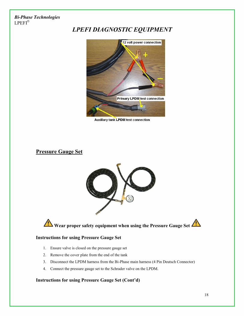
Pressure Gauge Set
Wear proper safety equipment when using the Pressure Gauge Set
Instructions for using Pressure Gauge Set
1. Ensure valve is closed on the pressure gauge set
2. Remove the cover plate from the end of the tank
3. Disconnect the LPDM harness from the Bi-Phase main harness (4 Pin Deutsch Connector)
4. Connect the pressure gauge set to the Schrader valve on the LPDM.
Instructions for using Pressure Gauge Set (Cont’d)

Bi-Phase Technologies LPEFI
LPEFI DIAGNOSTIC EQUIPMENT
19
a. Remove the Schrader valve cap
b. Remove the Brass adapter from the pressure gauge set
c. Screw brass adapter firmly onto the shrader valve
d. Firmly insert the pressure fitting back onto the brass adapter
e. Pressure set is now ready to use

Bi-Phase Technologies LPEFI
BASIC DIAGNOSTICS
20
Introduction The LPEFI system was developed and designed for use on modern sequential fuel injected gasoline engines. The design intent was to allow direct replacement of the gasoline fuel system to the LPEFI
system with no change in the original gasoline electronic engine control strategy or onboard diagnostics. With this said, it is very important that a technician understands electronic engine management theory. In this section we will not attempt to write the book on electronic engine control or self-diagnostics, but briefly explain some theory and operation of the general idea of electronic engine management and some areas that will help in the diagnosis of the LPEFI system. For details on specific vehicles you should refer to the OEM repair manuals. Electronic Engine Management Power-train control module – The PCM monitors engine operating conditions by input received from engine sensors. Control output actuators supply the function of fuel supply, incoming air, timing, ignition, EGR, evaporative emission control to provide the demanded operating condition the driver or the PCM desires based on the inputs from the engine sensors. The implementation of electronic engine management brought many benefits:
1. Improved exhaust emissions, 2. Improved power, 3. Improved fuel economy, 4. Improved durability & reliability, and 5. On-board self diagnostics.
Since the first generations of electronic engine management (around 1980) many improvements have been made. Today all vehicle manufacturers comply with the standards of OBD II (on-board diagnostics second generation). OBD II did drastically change the way electronic engine management is carried out but it did not change the original input versus output control strategy. It did require that the names for sensors and actuators used are common from manufacturer to manufacturer, the same data link connector be used and a generic list of trouble codes and data are retrievable by aftermarket diagnostic scan tools. In addition, more monitors were added to track degradation of emission control components and warning flags that would turn on the malfunction indicator lamp for things like cylinder misfire or catalytic converter failure. Manufacturers began implementation of OBD II as early as 1994 on select vehicles with a goal to be completed with light duty trucks by 1996. Today, they are still adding to it and implementing it on heavier vehicles. The engine control system consists of the PCM, relays, modules, sensors, switches and actuators. The PCM sends out electrical reference signals to engine sensors and then analyzes the return signals. The engine sensors supply specific information to the PCM, in the form of electrical signals, to determine engine operating conditions. In the event of a sensor or actuator failure, the PCM initiates an alternative strategy or failure mode to allow the vehicle to maintain drivability. In the event of PCM failure a limited operating strategy will be activated. This provides minimal engine operation and any self-test or feedback systems will stop. The malfunction indicator lamp will come on and stay on until the vehicle is repaired or until the PCM has determined that all signals have returned within operating limits and then the PCM will resume normal operation. Vehicles are equipped with different combinations of input devices. Not all devices are used on all models. To determine the input devices used on a specific model refer to the appropriate OEM repair manual and wiring diagrams.

Bi-Phase Technologies LPEFI
BASIC DIAGNOSTICS
21
Electronic Engine Management, cont’d Some common input devices
Crankshaft position sensor Camshaft position sensor Engine coolant temperature sensor Inlet air temperature sensor Oxygen sensor Throttle position sensor Mass air flow sensor Manifold absolute pressure sensor Vehicle speed sensor EGR position sensor Knock sensor
Output signals are signals that send a demand to an actuator; some common actuators Fuel injectors Fuel pump Idle air control or idle speed control EGR control Canister purge control solenoid Spark control MIL (malfunction indicator lamp) Transmission controls
There are many more inputs and outputs, these are some common ones. Vehicles are equipped with different combinations of computer-controlled components. Not all vehicles are equipped with the same components. Always refer to the specific OEM repair manuals and information. Self-Diagnostics With the capability to see data through the use of a scan tool and to verify areas of trouble by checking for diagnostic trouble codes, today’s electronics have given us more ways to verify where and what the problem might be. Each vehicle manufacturer has written steps in troubleshooting a vehicle. If the scan tool leads you to a specific trouble area refer to the OEM written test to troubleshoot accurately. Some aftermarket manuals are very good in diagnosing electronic engine controls. To prevent the replacement of good components and wasting time, verify engine condition and basic tune-up requirements before condemning electronic engine control components. If your scan tool immediately warns of a bad sensor, check it first but remember that an out-of-tune engine or an engine with internal mechanical deficiencies can trigger diagnostic trouble codes. DTCs, (Diagnostic Trouble Codes) are generated when there is a gross error with a sensor signal, input or output signal, or the PCM can no longer control a specified function such as fuel mixture, timing, EGR, canister purge and so on. Many times a DTC is generated but the fault is not necessarily the same as the DTC. For example, a vacuum leak may cause an oxygen sensor activity code or a fuel control code. In this situation the vacuum leak is the problem but it affected the electronic control of fuel which could cause you to replace an injector if you did not check thoroughly or even the replacement of an oxygen sensor. Always remember the basics and eliminate all the easy things first.

Bi-Phase Technologies LPEFI
BASIC DIAGNOSTICS
22
Self-Diagnostics, cont’d Retrieving DTC’s (Diagnostic Trouble Codes) is always a good place to start when trouble shooting a problem. If there are multiple DTC’s, you need to evaluate them and troubleshoot with the first DTC listed. Write down all the DTC’s listed and investigate what each one stands for. Open up the data information available and investigate the area of concern established by the DTC’s listed. See if there is any correlation between the DTC and the data associated with it. Many times you may find that the data reveals proper function and there is no reason for generating a DTC. If this is the case, look at the freeze frame data, if available, and see under what conditions the DTC was generated. This will help in diagnosing the problem. The datastream information is very helpful. First, you can look at sensor and actuator activity live in real time. This is very effective diagnostics. Today, it is very important that a technician knows and understands on-board diagnostics. It can save time and money, which benefits both the technician and the customer. When diagnosing the LPEFI system, there are some PID values you may want to look at from the data stream.
ECT (engine coolant temperature) IAT (intake air temperature) IAC (idle air control) STFT B1 and B2 (short term fuel trim bank 1 and bank 2) LTFT B1 and B2 (long term fuel trim bank 1 and bank 2) PW B1 and B2 (average injector pulse width bank 1 and bank 2) 02S11 (oxygen sensor bank 1 front sensor) 02S21 (oxygen sensor bank 2 front sensor)
It is very important that you know the meaning of the PID (parameter identification) names in the data stream and understand the values displayed. In this manual we will only talk about a few of these terms. Refer to OEM repair manual for a more detailed explanation. Many of the PID addresses are easy to identify but some of the acronyms are confusing, and having an OEM repair manual or Mitchell manual is very helpful. The more you work with electronic diagnostics the more familiar you will become. Important PIDs, Explanation ECT (engine coolant temperature) – The data is displayed as degrees F or C depending on your selection for English or Metric display. Engine coolant temperature is important because the learning function of the computer does not begin until the engine reaches a programmed temperature. This temperature may vary depending on vehicle model. For example a Ford may not begin to learn until the temperature reaches 165
degrees F. Always perform final diagnosis when the engine is at full operating temperature. IAT (intake air temperature) – The data is displayed as degrees F or C depending on your selection for English or Metric display. IAC (idle air control) – The data is displayed in % or counts. % is the percent of time it is on, 50% would be half open or 75% would ¾ open. Counts would be the same, the higher the count the more open the valve is. This could be important when a vacuum leak is suspected. Always refer to the OEM repair manual for the operating range as each model varies. STFT B1 or B2 (short term fuel trim) – This is displayed either in positive or negative percentages (%) or in counts. Short term fuel trim is adjustments to fuel delivery, as it is happening at the moment you look at it. The closer to 0% or 128 counts the better the fuel control is. A negative percentage indicates a rich condition and the fuel control is subtracting fuel or adjusting the fuel delivery leaner while a positive percentage is a lean condition and fuel control is adding fuel or adjusting the fuel delivery richer.

Bi-Phase Technologies LPEFI
BASIC DIAGNOSTICS
23
Important PIDs, Explanation (Cont’d) STFT B1 or B2, cont’d If it is displayed in counts the range for counts is 0 to 255. The middle of the range is 128 and any reading less than 128 is a rich condition while any reading greater than 128 is a lean condition. This does not mean the engine is running rich or lean, but means that fuel delivery is rich/lean and fuel control is adjusting from that point to optimize fuel delivery for emissions, economy and drivability. If the range of control reaches the limit, lean or rich, then the engine is running lean or rich and the computer can no longer control the fuel mixture and a DTC will be logged in the computer’s memory. If the computer recognizes this in a second drive cycle it will illuminate the MIL, (malfunction indicator lamp or check engine light). The STFT has a back up to extend its range of control. It is called LTFT, long term fuel trim, and if the STFT is controlling too far to the lean or rich side of the middle of the range of control, the LTFT will learn and allow the STFT to control closer to the middle of the range. This allows the STFT to have a much longer time period of control. This allows the degradation of the air filter, the fuel filter, fuel injectors, engine oil contamination, PCV, fuel pump and anything that can affect fuel and air delivery. For example, when a very dirty air filter is replaced the fuel control will readjust over time or the same with a fuel filter or the same after an injector is replaced. LTFT (long term fuel trim) – This is displayed in either positive or negative percentages (%) or in counts. It is also shown for bank one and bank two. Long term fuel trim is adjustments to fuel delivery over time. The closer to 0% or 128 counts the better the fuel control is. A negative percentage indicates a rich condition and the fuel control is subtracting fuel or adjusting the fuel delivery leaner, while a positive percentage is a lean condition and fuel control is adding fuel or adjusting the fuel delivery richer. If it is displayed in counts the range for counts is 0 to 255. The middle of the range is 128 and any reading less than 128 is a rich condition while any reading greater than 128 is a lean condition. This does not mean the engine is running rich or lean, but means that fuel delivery is rich/lean and fuel control is adjusting from that point to optimize fuel delivery for emissions, economy and drive ability. If the range of control reaches the limit, lean or rich, then the engine is running lean or rich and the computer can no longer control the fuel mixture and a DTC will be logged in the computer’s memory. If the computer recognizes this in a second drive cycle it will illuminate the MIL, (malfunction indicator lamp or check engine light). LTFT levels adjust over time as previously mentioned and causes or allows the STFT to maintain control closer to the middle of the control range. This allows rapid changes to fuel control for better response and performance. The LTFT is like a fine-tuning function. This gives the STFT a much longer time period of control. This allows the degradation of the air filter, the fuel filter, fuel injectors, engine oil contamination, PCV, fuel pump and anything that can affect fuel and air delivery. For example, when a very dirty air filter is replaced, the fuel control will readjust over time or the same with a fuel filter or the same after an injector is replaced. If the battery is changed or disconnected it will reset fuel trim and a learning process could take a few hundred miles. However, for diagnosis purposes bringing the vehicle to full operating temperature and a short drive will give you an idea of where the controls stabilize. Anytime the STFT values are stabilized close to the middle of the range of control the LTFT values should be accurate. If the air filter is clean, the engine oil is not contaminated and the engine condition is good the LTFT values are a good indicator of how well the injectors are calibrated. It is also helpful to review the LTFT values at different load conditions, such as cruising at 45 mph or at a wide open throttle situation. If power seems low and wide open throttle values are very lean this would give you something to look for.

Bi-Phase Technologies LPEFI
BASIC DIAGNOSTICS
24
Important PIDs, Explanation, (cont’d) The LPEFI system will not have LTFT values as good or as close to the middle of the control range as gasoline injectors. What we want to look for when diagnosing the LPEFI system is for the values to be within 10% or about 40 counts of each other. For instance –2% bank one and –8% bank two would be okay. It is normal to also see LTFT values at -17% on either bank but we would not want to see a richer condition or -20% numbers. If the LTFT values are on the leaner end of the control range, other problems may exist if the value is higher than +12% or 176 counts. Four counts equal approximately 1%. PW (injector pulse width) – The length of time the injector solenoid is energized or the injector is open, displayed in milliseconds and averaged for each bank of the engine. Naturally the injector pulse width is lower at idle than it is at cruise and higher than cruise during a loaded condition. Comparing the PW values could identify an area of concern. For example, if you identified a weak injector during the fuel injector check in the basic diagnostic procedure section of this manual, it could show up here by displaying a different PW on the bank that had the weak injector. Most of the time, injector pulse width will be between 2 and 5 milliseconds at idle. The scan tool only displays an average pulse width for each bank of cylinders. Each bank is normally within a few tenths of each other. If not, refer to checking fuel injectors in basic diagnostic procedures. O2S11 or HO2S11 – Oxygen sensor or heated oxygen sensor bank one sensor one O2S21 or HO2S21 – Oxygen sensor or heated oxygen sensor bank two sensor one Most oxygen sensors today are equipped with an internal heater to speed up the amount of time it takes for electronic engine management to reach closed loop. An oxygen sensor is not active until it reaches a temperature of approximately 570 degrees F. Oxygen sensors create voltage and can be called a galvanic battery. A low voltage signal is a lean fuel mixture indication and a high voltage signal is a rich fuel mixture indication. The maximum voltage an oxygen sensor will generate is approximately 1000 millivolts or one volt. The oxygen sensor actually measures oxygen content in the exhaust stream. If a rich mixture exists, there is a lack of oxygen compared to the outside ambient atmosphere. This lack of oxygen causes the oxygen sensor to create voltage. If the amount of oxygen in the exhaust stream is equal to the amount in the atmosphere, no voltage will be generated. Oxygen sensors are sensitive to silicones and could become coated and decrease the reaction time or activity. Oxygen sensor signal is something worth verifying and not only at idle, but at different engine load conditions. Most vehicles today consider an oxygen sensor signal of 0.45 volts as stoichiometric. The fuel control is based on oxygen sensor voltage and if fuel control is working properly, oxygen sensor voltage will move below and above the 0.45 volts. The number of times in a given period that the oxygen sensor signal crosses above or below the 0.45 volts is called cross counts and the PCM monitors this activity to know how fuel control is functioning as well as for fuel delivery decisions.

Bi-Phase Technologies LPEFI
DIAGNOSTICS
25
All Models Introduction The following diagnostic steps may help prevent overlooking a simple problem. The first step in diagnosing any drive-ability problem is verifying the customer’s complaint with a test drive under the conditions the problem reportedly occurred. Always perform a careful and complete visual inspection first. Most engine control problems result from mechanical breakdowns, poor electrical connections or damaged/misrouted vacuum hoses. Before condemning the LPEFI system, perform each test listed in this article. Visual Inspection Visually inspect all electrical wiring, looking for chafed, stretched, cut or pinched wiring. Ensure electrical connectors fit tightly and are not corroded. Visually inspect for any loose or drop harness looms coming in contact with the injector rails or components. Visually inspect all vacuum hoses and ensure they are properly routed – not pinched, cut or disconnected. Visually inspect the secondary ignition wires, spark plugs and ignition coils. Ignition weakness shows up much sooner on propane fueled engines than a gasoline engine. Visually inspect each, injector insulator housing for cracks, cuts or o-ring sealing at the manifold or at the top o-ring of the insulator housing (injector repair in this manual). Listen to the fuel pump operation and the opening “click” of the fuel supply valve. Initiate a purge cycle by opening the door or turning on the ignition key (purge logic chart in this manual). Preliminary Checks Check that the following systems and components are in good condition and operating properly before diagnosing problems in the LPEFI fuel system.
1. Battery condition 2. State of tune (ignition system) 3. All wiring and vacuum connections 4. Air cleaner and ducting 5. Cooling system
Mechanical Inspection
Warning: DO NOT use the ignition switch during compression test on fuel injected vehicles. Use a remote starter to crank the engine. Fuel injectors on many models are triggered by the ignition during cranking mode, which can cause a flammable fuel mixture in the intake manifold when performing a compression test. Compression – Check engine mechanical condition with a compression gauge, vacuum gauge or an engine analyzer. Compression pressures are considered within specifications if the lowest reading cylinder is within 75 percent of the highest reading cylinder.

Bi-Phase Technologies LPEFI
DIAGNOSTICS
26
Mechanical Inspection, cont’d Exhaust system back pressure – The exhaust system can be checked with a vacuum or pressure gauge. Remove the O2 sensor and connect a 0-5 psi pressure gauge. Run the engine at 2500 RPMs and if the exhaust back pressure is greater than 1¾ to 2 psi, the exhaust system or catalytic converter is plugged. If a vacuum gauge is used, connect the vacuum gauge hose to an intake manifold port and start the engine. Observe the vacuum gauge. Open the throttle part way and hold steady. If the vacuum gauge reading slowly drops after stabilizing, the exhaust system should be checked for a restriction. Also, if the vacuum gauge will not drop below 3” Hg on a wide open throttle condition or WOT loaded condition, check the exhaust system for restriction. Leaks in the exhaust system, if upstream from an O2 sensor, can also cause fuel control problems due to oxygen dilution in the exhaust, which causes inaccurate O2 sensor response. Fuel System Engine does not crank – Check for hydrostatic lock (water or liquid in a cylinder). Repair as needed. Check for starting and charging system problems. Engine cranks but will not start
1. Check fuel tank contents and fuel gauge accuracy 2. Check ignition system for good secondary current at the spark plugs – if no spark exists or if spark
is weak, repair ignition system problem first 3. Check fuel lines and fittings for leaks – if no leaks are found, check fuel delivery system for
proper pressure; check for +12 volts to fuel delivery system 4. Check for defective fuel injector; a leaking fuel injector could cause a rich (flooded) condition and
cause a no-start; initiate a purge cycle and after the purge cycle is complete listen at the intake manifold for injector leaks; open the throttle plate, smell and listen, pull the PCV valve and smell and listen, lift the injector rail out of the manifold (without disconnecting fuel line) and visually inspect
5. Check the ECT, coolant temperature sensor – confirm the ECT is in proper working condition and also confirm that the LPEFI system ECT is in place or investigate if the LPEFI system uses a sensor or PCM calibration for cold start fuel enrichment strategies; if the sensor is faulty or the sensor was not installed or the PCM was not calibrated (depends on which cold start enrichment correction is used), a gasoline start up fuel enrichment strategy can cause a no-start condition. Refer to Page 8
Warning: Always relieve fuel pressure before disconnecting any fuel injection related component. DO NOT allow uncontrolled fuel release. Never loosen fittings or vent any propane unless you are wearing insulated PVC rubber gloves; escaping liquid propane can cause frostbite and severe freeze burns. Do not disconnect any propane hoses or remove any injectors unless the fuel lines have been properly drained completely. Never release fuel indoors or in an area where vapors could accumulate – source of ignition could ignite the air fuel mixture and cause severe injury and property damage.
Fuel Pressure Release To prevent the fuel pump and fuel supply valve from opening during repair, disconnect battery and/or electronic tank control box – always disconnect negative battery terminal first. For more information please see “Draining the Fuel Lines” section of this manual
1. Remove the fuel system Schrader Valve cap on the LPDM or “Y” and prepare to connect the fuel pressure test gauge (note: the “Y” has been eliminated on 2005 and newer models)
2. The fuel pressure test gauge has a long drain hose; route the drain hose to a flare stack or other receptacle for flammable propane vapor; never release propane indoors. See page 18
3. Install the brass collar from the fuel pressure test gauge to the Schrader Valve, with the grooved end facing out

Bi-Phase Technologies LPEFI
DIAGNOSTICS
27
Fuel Pressure Release, cont’d
4. Make sure the small thumb valve next to the gauge on the Bi-Phase gauge set is closed 5. Connect the test gauge to the collar; this connection will press the center pin on the Schrader
Valve releasing propane into the hose; this is a sensitive connection and must be confirmed; if the pressure gauge does not react or reacts slowly, push in on this connection to confirm it has penetrated the center pin of the Schrader Valve; the brass collar has some adjustments and may also require oiling the o-ring occasionally
6. Open the valve near the pressure gauge to drain the propane through the long hose; note that the Schrader Valve does not drain the tank – it only drains the main fuel line and the injectors
7. When the gauge reads “0” and there is no pressure exiting the end of the hose, you may disconnect the fuel lines or injectors as needed (more detailed procedures and photos on page 18)
Warning: Do not remove the LPDM or any tank valves from the tank at this time. Propane tank is under pressure. The procedure described previously only drains the fuel lines for service. Serious injury or death could occur.
Fuel Pressure Internal tank pressure must be established first. Use the 3-switch diagnostic box from Bi-Phase Technologies, turn on the fuel supply valve rocker switch and push the fuel return valve “push” switch. Hold down the fuel return valve switch for 30 seconds or until fuel pressure stabilizes. This is internal tank pressure. When checking fuel pressures over a given time always recheck internal tank pressure due to changes in ambient temperature. Fuel pressure with return valve open (all models) – With the return valve open or during a purge cycle the fuel pressure will be 5 to 15 psi below normal operating pressure (internal tank pressure plus boost pressure). Should the pressure drop more than 15 psi. Evacuate the fuel in the fuel lines (reference the procedures in this manual), remove the primary hose and inspect the white nylon inner liquid supply line in the primary hose at the LPDM. It could require that you visually inspect all hoses for proper inner liquid supply line length. Fuel pressure should always be confirmed first. If fuel pressure is not within specification the system will malfunction. Fuel pressure can cause many types of drive ability complaints.

Bi-Phase Technologies LPEFI
DIAGNOSTICS
28
Concentric Fuel Lines As previously discussed, the fuel lines of the LPEFI system are a concentric design. They permit fuel supply and fuel return to be accomplished inside one fuel hose. There are many benefits to this design as mentioned in the theory section of this manual. The sealing of the white nylon inner line to all the specific components of the system is very critical. If this seal is lost, damaged or not made the vehicle will experience hard starting when hot, reduced power under load, unbalanced injectors (rail to rail or bank to bank) and in extreme cases a no-start condition. It may be slightly difficult to install the lines and caution should be taken when assembling the concentric fuel lines. Extreme caution should be used with loop hoses and -6 primary fuel lines. The inner lines in these applications are small and easily crimped (kinked) during installation to the fuel rail. Also damage to the O ring seal in the rail may occur. (Note: The secondary lines and the “Y” have been eliminated on 2005 and newer models and replaced with a single secondary “loop hose” that connects the two rails to each other. Some 2013 models have two primary lines running from the YLPDM) Coat the metal hose end fitting and the white nylon inner line with a small amount clean motor oil before attempting installation. If the white nylon inner line is crimped during installation or repair of the system a new hose assembly must be obtained. The white nylon inner line is custom fit to each larger outer hose. Do not assemble the hose with a crimped inner line; it will cause drive-ability problems. Do not cut the inner line under any circumstance as this will cause drivability issues. With exception of the GM 7.4L fuel injector rail, each white nylon inner line is sealed by a single o-ring located below the inner line alignment bushing (finger bushing). This is found in each hose port whether it is the LPDM, the “Y” or the injector rail end fitting. See illustration below.
O-ring
Injector rail end fitting & hose utilizing 3/8” quick disconnect much like gasoline. YLPDM’s have the same connection
Typical “Y” or LPDM connection utilizing split collar halves to lock the hose into the hose port

Bi-Phase Technologies LPEFI
DIAGNOSTICS
29
Fuel Injectors Fuel Injector check
1. Connect a tachometer to the engine; run the engine at idle; disconnect and reconnect injectors individually (this may also be accomplished with a scan tool); if each injector causes a momentary drop in engine speed of at least 100 RPMs, injectors are giving proper fuel delivery; RPM drop should only be momentary as the IAC (idle air control) will attempt to reestablish correct idle RPM
2. Any injectors that do not give a 100RPM drop will need further investigation. Use a pair of injector noid lights to verify injector wiring harness is working properly. If not investigate injector wire harness for opens/shorts. Remove the “bad” injector and switch with a good injector on the rail to ensure problem follows the injector.
3. With the system pressurized listen, smell, spray with leak detection fluid and visually inspect injectors for fuel leaks from the injector tip and housing; open the throttle plate to listen and smell, or without disconnecting the fuel lines lift the injector rail out of the intake manifold to visually verify that no injector leaks fuel; if an injector sprays fuel or leaks externally without an electrical demand, the injector must be replaced
4. The fuel injector housing is a heat insulator and is installed over the injector itself, even though it may look as one piece; the injector insulator housing is sealed onto the injector with one or two o-rings, depending on the design revision level of the injector; the early single o-ring sealed injector housing may lose its seal causing a vacuum leak; an injector should hold a vacuum if checked from the bottom of the housing with a hand operated vacuum pump (reference injector repair in this manual)
5. The fuel injectors are calibrated for each specific engine on 2005 or earlier model year vehicles ; injectors are also assembled on each rail within a specific range of flow; if an injector from a different engine family is installed it could cause an out-of-balance situation and set a diagnostic trouble code in the PCM. Vehicles equipped after 2005 use the same injector, but insulating housing may have internal variance. Please contact Bi-Phase Technologies for more information
Fuel injector circuit – Disconnect all injector harness connectors. Use a digital ohmmeter to check resistance across the terminals of each injector. The nominal resistance for each injector is 12.6 to 13.8Ω. An acceptable range is 12Ω to 15Ω, but not to exceed 2Ω between the lowest reading injector to the highest reading injector. If there is greater than 2Ω difference, choose and replace the highest or lowest resistance injector, whichever corresponds, to achieve a range inside 2Ω. If the resistance test proves an open circuit the injector must be replaced. Refer to the OEM service manual and wiring diagram for more information if the wiring harness is at fault.

Bi-Phase Technologies LPEFI
DIAGNOSTICS
30
Ignition Checks (Note: On many newer vehicles if an ignition failure occurs, the ignition system may continue to operate with limited ability. Diagnostic trouble codes should be present if this occurs and the engine may be hard to start. The ignition timing will also be fixed or no change in timing with RPM or load changes.) Initial Inspection
1. Visually inspect ignition system components and wiring for evidence of damage or loose connections; check condition of spark plugs, spark plug wires and distributor cap and rotor (if equipped); repair or replace damaged components
2. Ensure idle speed and ignition timing is correct; check all components that could affect ignition timing; refer to OEM specifications Crankshaft position sensor Camshaft position sensor and/or sensor timing Crankshaft end play Timing belt or timing chain condition, worn timing gears, chain or belt can cause erratic
timing MAP or MAF sensor signals For more detailed information refer to the OEM repair manual
3. Ensure spark plug wires are properly connected and routed in correct firing order 4. Check for spark – Disconnect a spark plug wire from a spark plug; connect a spark plug tester
between the spark plug wire and ground; crank engine and check for a strong consistent spark; repeat test for each spark plug wire; if no spark is present check ignition coil primary wiring, coil output or refer to OEM repair manual; if spark appears to be inconsistent do the same as previously mentioned, but confirm the condition of the spark plug wire and repeat test; an ignition scope analyzer is also recommended for checking ignition condition; an approved spark plug tester must be used to prevent damage to ignition control components
5. Using a digital ohmmeter check the resistance of each spark plug wire; high tension wire resistance should be 4000 to 7000Ω per foot; replace as necessary
6. Check power to coil – Disconnect primary wiring to coil/coils; turn on ignition and measure voltage of primary positive voltage wire to coil connector; if less than 10 volts repair battery condition or primary positive voltage wire
7. Check coil/coils – Disconnect coil, using a digital ohmmeter measure resistance of ignition coil between primary wire terminals; measure resistance between ignition coil’s secondary terminals and positive primary terminal; refer to appropriate OEM repair manual for exact resistance values

Bi-Phase Technologies LPEFI
DIAGNOSTICS
31
LPDM DIAGNOSTIC FLOW CHART (NO SCAVENGE PUMP)
Begin
Return Solenoid
Turn the return solenoid switch on and
off.Does it click and is the amp draw between 1 –
2 amps?
Connect 3-switch test box (3SB) to main tank LPDM harness connector (4 pin) Connect the clamps to a 12v source. Connect the gauge set to the schader valve on the LPDM
Supply Solenoid
Turn the supply solenoid switch on
and off.Does it click and is
the amp draw between 1 -2 amps?
LPDM will need to be replace
Continue to next
page for pressure
test
Pump
Turn the pump switch on and off. Can you hear the pump
running? (Test pump for only a few seconds) May run for a few seconds and quit running. Can
draw over 15 amps
Each output from the 3SB should produce +12v when it is active (expect for the ground wire.
The supply solenoid (orange wire) and return solenoid (yellow wire) should each have 5 -10 ohms resistance to ground (black wire)The pump (red/white stripe) should have 1-4 ohms resistance to
ground (black wire)
Pump will need to be replaced
Verifiy there is fuel in the tank
Yes
No
No
No
Yes
Yes
LPDM Diagnostic Flow Chart
Rd/
wt 1
4
Orn
18
AW
G
Yel
18
AM
G
Blk
14
AW
G
Fuel Pump
Return solenoid
Supply solenoid
Verify 12V battery source.

Bi-Phase Technologies LPEFI
DIAGNOSTICS
32
Continued from previous
page
Verifiy there is fuel in the tank
Tank Pressure
Turn on the supply switch. Depress the return switch and hold for 30 seconds until the
pressure stabilizes.
Turn off all switches on 3SB.What is the tank pressure?
Record tank pressure.
Pump Boost
Turn on Supply switch on 3SB.Turn on pump switch on 3SB
What is the pump boost pressure?
Record boost pressure
Purge Reduction
Supply switch onPump switch on
Depress return switch. What is the pressure? Does the pump change pitch when turn on/off?
Record the pressure
Is boost pressure 35-50 PSI above tank pressure and amp draw between 6 and 10 amps
Is the purge reduction 2-15 PSI below pump boost
pressure?
Fuel System has passed
Yes
No
Yes
No
Same as tank pressure and less than 5 amp
draw 1-30 PSI above tank pressure and above 5
amps draw
Tank is empty, or fuel hose isn’t connect to fuel pump, or pump
has failed. Follow tank evacuation procedures
Pump has failed or inner hose is not engaged properly. Follow
tank evacuation procedure.
Inner hose is not engaged properly.
LPDM Diagnostic Flow Chart
Verify 12V battery source.

Bi-Phase Technologies LPEFI
DIAGNOSTICS
33
LPDM DIAGNOSTIC FLOW CHART (W/SCAVENGE PUMP)
Begin
Return Solenoid
Turn the return solenoid switch on and
off.Does it click and is the amp draw between 1 –
2 amps?
Connect 3-switch test box (3SB) to main tank LPDM harness connector (4 pin) Connect the clamps to a 12v source. Connect the gauge set to the schader valve on the LPDM
Supply Solenoid
Turn the supply solenoid switch on
and off.Does it click and is
the amp draw between 1 -2 amps?
LPDM will need to be replace
Continue to next
page for pressure
test
Pump
Turn the pump switch on and off. Can you hear the pump
running? (Test pump for only a few seconds) May run for a few seconds and quit running. Can
draw over 15 amps
Each output from the 3SB should produce +12v when it is active (expect for the ground wire.
The supply solenoid (orange wire) and return solenoid (yellow wire) should each have 5 -10 ohms resistance to ground (black wire)The pump (red/white stripe) should have 1-4 ohms resistance to
ground (black wire)
Pump will need to be replaced
Verifiy there is fuel in the tank
Yes
No
No
No
Yes
Yes
LPDM Diagnostic Flow Chart
Rd/
wt 1
4
Orn
18
AW
G
Yel
18
AM
G
Blk
14
AW
G
Fuel Pump
Return solenoid
Supply solenoid
Verify 12V battery source.
Supply Solenoid Turn on the Supply Solenoid
switch. Is there an audible click? Do you hear scavenge pump
running? Is amp draw 1-3 amps?
Pump Turn on the Supply Solenoid
switch. Turn on the Pump Switch. Do you hear the pump running? Is
amp draw 5-7amps?
Replace LPDM/Scavenge Pump

Bi-Phase Technologies LPEFI
DIAGNOSTICS
34
Continued from previous
page
Verifiy there is fuel in the tank
Tank Pressure
Turn on the supply switch. Depress the return switch and hold for 30 seconds until the
pressure stabilizes.
Turn off all switches on 3SB.What is the tank pressure?
Record tank pressure.
Pump Boost
Turn on Supply switch on 3SB.Turn on pump switch on 3SB
What is the pump boost pressure?
Record boost pressure
Purge Reduction
Supply switch onPump switch on
Depress return switch. What is the pressure? Does the pump change pitch when turn on/off?
Record the pressure
Is boost pressure 35-50 PSI above tank pressure and amp draw between 6 and 10 amps
Is the purge reduction 2-15 PSI below pump boost
pressure?
Fuel System has passed
Yes
No
Yes
No
Same as tank pressure and less than 5 amp
draw 1-30 PSI above tank pressure and above 5
amps draw
Tank is empty, or fuel hose isn’t connect to fuel pump, or pump
has failed. Follow tank evacuation procedures
Pump has failed or inner hose is not engaged properly. Follow
tank evacuation procedure.
Inner hose is not engaged properly.
LPDM Diagnostic Flow Chart
Verify 12V battery source.

Bi-Phase Technologies LPEFI
DIAGNOSTICS
35

Bi-Phase Technologies LPEFI
DIAGNOSTICS
36
AMPERAGE TEST (Turbine Pump)
Connect a "3 switch box" to the LPDM. The following test is based on a truck with a fully charged battery and with the engine off. If the engine is running or you are charging the battery the voltage will be higher and the resulting amperage will be higher. A low battery will give lower amperage values.
"3-Switch" Positions Things to Notice
Current Draw
Fuel Pressure
Mode of Operation Discussion
SUP RET PMP
OFF OFF ON High Pitch
Squeal; Pump Dead-Heading
Above 13A
Tank Pressure or
Less (Pump Dead-Headed)
Pump is pushing against a closed
supply valve.
ON OFF ON
Solenoid has audible "click"
when turned on, Pump Sounds
Normal
7-9A Tank
Pressure +45-65psi
Normal Operating Mode
Fuel is pumped through the fuel rails and back to the tank.
This is the normal operating condition.
ON OFF ON No "Click" when
supply valve switch turned on
Above 13A
Tank Pressure or
Less Supply Valve Failure
Pump is pushing against a closed
supply valve. Supply valve failure due to
mechanical or electrical failure.
ON ON ON
Solenoids have audible "Click" when switches are turned on, normal pump
sound
8-10A
5-15PSI less than operating pressure
Purge Mode
Purge mode. When vehicle is in any purge
mode valves and pump should be operating in this
condition
ON ON ON Return Solenoid
has no "click" when turned on.
7-9A Operating pressure
Return Valve Failure
Truck will have normal running mode. May experience poor hot
start

Bi-Phase Technologies LPEFI
DIAGNOSTICS
37
AMPERAGE TEST (Turbine Pump W/ Scavenge Pump)
Connect a "3 switch box" to the LPDM. The following test is based on a truck with a fully charged battery and with the engine off. If the engine is running or you are charging the battery the voltage will be higher and the resulting amperage will be higher. A low battery will give lower amperage values.
"3-Switch" Positions Things to Notice
Current Draw
Fuel Pressure
Mode of Operation Discussion
SUP RET PMP
OFF OFF ON High Pitch
Squeal; Pump Dead-Heading
Above 13A
Tank Pressure or
Less (Pump Dead-Headed)
Pump is pushing against a closed
supply valve.
ON OFF ON
Solenoid has audible "click"
when turned on, Pumps Sounds
Normal
8-10A Tank
Pressure +45-65psi
Normal Operating Mode
Fuel is pumped through the fuel rails and back to the tank.
This is the normal operating condition.
ON OFF ON No "Click" when
supply valve switch turned on
Above 13A
Tank Pressure or
Less Supply Valve Failure
Pump is pushing against a closed
supply valve. Supply valve failure due to
mechanical or electrical failure.
ON ON ON
Solenoids have audible "Click" when switches are turned on, normal pump
sound
9-11A
5-15PSI less than operating pressure
Purge Mode
Purge mode. When vehicle is in any purge
mode valves and pump should be operating in this
condition
ON ON ON Return Solenoid
has no "click" when turned on.
8-10A Operating pressure
Return Valve Failure
Truck will have normal running mode. May experience poor hot
start
ON OFF OFF
Supply Solenoid has audible "click" when turned on.
Scavenge pump sounds normal
8-9A Tank
Pressure Scavenge Pump Normal
Operating Mode
Scavenge pump operating correctly. Please see more info about the scavenge pump in this manual
ON OFF OFF
Supply Solenoid has audible "click" when
turned on. No audible pump
7-8A Operating pressure
Scavenge Pump Failure
Truck will have normal running mode.
Useable fuel range may decrease

Bi-Phase Technologies LPEFI
DIAGNOSTICS
38
TROUBLESHOOTING BY SYMPTOM Introduction Before diagnosing symptoms or intermittent faults, perform steps in basic diagnostic procedures and appropriate self-diagnostics with a scan tool. Use this section to diagnose problems existing when DTCs, diagnostic trouble codes, are not present. Symptom checks can direct the technician to malfunctioning component(s) for further diagnosis. A symptom should lead to a specific component test and/or adjustment. Symptoms Symptom checks cannot be used properly unless the problem occurs while the vehicle is being tested. To reduce diagnostic time, ensure basic diagnostic procedures and self-diagnostics were performed before diagnosing a symptom. Some symptoms are: No crank Hard start cold/long crank Hard start hot/long crank No start/normal crank Low idle speed High idle speed Rough idle Stalls but restarts (hot or cold) Stalls but does not restart Stalls during acceleration Stalls during deceleration Stalls during steady speed driving Stalls after vehicle stops Stalls when put in gear Stalls while idling Starts but stumbles and stalls Hesitates Surges Backfires, misfires or cuts out during
acceleration Backfires, misfires or cuts out during
deceleration Bucks & jerks Engine knocks or rattles, spark knocks Loss of power during cruise or all the time Loss of power during heavy load condition,
wide open throttle Poor fuel economy Failed emissions
Runs rough all the time
High oil consumption Engine runs hot Engine runs cold Fire comes out of exhaust
LPEFI Specific Symptoms Smell of propane Slow fuel filling or no fill Unable to evacuate fuel lines through
Schrader Valve No fuel transfer from optional secondary
transfer tank Noisy fuel pump or noise in tank Fuel pump does not shut off No purge cycle Injector leaks with no electrical command Injector insulator housing cracked or not
sealing (vacuum leak) Symptom Diagnosis No Crank Check battery connections Check the start motor Check appropriate fuses and fuse links On A/T models check park/neutral safety
switch On M/T models check clutch switch Check starter circuitry Check for seized/hydro locked engine Check flywheel Check ignition switch Hard start cold/long crank Check battery charge condition Check ignition primary voltage during crank
& secondary wiring Check for vacuum leaks Check fuel pressure (pump boost) Check injectors for leakage, causing a
rich/flooded condition Check air cleaner & incoming air ducts

Bi-Phase Technologies LPEFI
DIAGNOSTICS
39
Symptom Diagnosis, cont’d Hard start cold/long crank, cont’d Confirm cold start strategy/PCM program or
LPEFI system coolant temperature sensor installed
See Calibration Codes in Specifications Section
Check engine mechanical condition, compression
Hard start hot/long crank Check battery charge condition Check ignition primary voltage during crank
& secondary wiring Check for vacuum leaks Check fuel pressure (pump boost) Check injectors for leakage, causing a
rich/flooded condition Check air cleaner & incoming air ducts for
restriction Check nylon inner liquid supply fuel lines
and the o-ring seals for the nylon inner line Check engine mechanical condition,
compression test No start/normal crank Check battery charge condition & fuel level Check the LPEFI system 20-amp fuse Check ignition primary voltage during crank
& secondary wiring Check for vacuum leaks Check fuel pressure including operation of
pump and supply & return valves Check wiring at electronic tank control box Check injectors for leakage, causing a
rich/flooded condition Check air cleaner & incoming air ducts for
restriction Check injector wiring harness & individual
injector connectors Check injector power wire voltage Check that injectors are delivering fuel Confirm cold start strategy/PCM program or
LPEFI system coolant temperature sensor installed, see page 8
Injector diagnosis Low idle speed Check idle air control wiring harness
connector or ETC, if equipped
Check base timing Check engine mechanical condition,
compression test Confirm IAC/ETC controls idle speed Check and/or adjust minimum idle, refer to
OEM repair manual for specification Check air cleaner and incoming air ducts High idle speed Check IAC/ETC wiring harness connector Check base timing Confirm IAC/ETC controls idle speed Check for vacuum leaks Check intake manifold gasket for vacuum
leaks Check and/or adjust minimum idle, refer to
OEM repair manual for specification Check EGR valve Check throttle linkage Check throttle plate for a closing obstruction Check incoming air intake ducts Check PCV Check canister purge vacuum lines &
evaporative emissions lines, if equipped before the LPEFI system installation
Rough idle Check ignition secondary wiring Check spark plugs Check for vacuum leaks Check PCV Check air cleaner and incoming air ducts &
sealing around MAF sensor Check fuel injector wiring harness and
individual injector electrical connectors Check fuel system operating pressure Check fuel injectors, conduct balance test as
described in basic diagnostic procedures Check engine mechanical condition,
compression test Check cooling fan blades for cracks or
bends Check for broken engine mounts Check all wiring connectors for intermittent
failure/disconnect Check for flooded condition/leaking fuel
injector, see basic diagnostic procedures

Bi-Phase Technologies LPEFI
DIAGNOSTICS
40
Symptom Diagnosis, cont’d Stalls but restarts (hot or cold) Check and/or adjust minimum idle speed per
the OEM repair manual specification Check IAC/ETC wiring harness connector Confirm IAC/ETC controls idle speed Check for vacuum leaks Check PCV Check for restricted air cleaner or incoming
air ducts Check MAF Check exhaust for restriction, see basic
diagnostic procedures Check EGR valve Check engine mechanical condition,
compression test Verify there are no leaking fuel injectors,
see basic diagnostic procedures Check for lean fuel injectors, verify long
term fuel trims Check fuel pressure Check wiring & wiring harness connectors
for intermittent failure/disconnect at electronic tank control box and all LPEFI
wiring connections & OEM connections Stalls but does not restart Check fuel pressure and confirm the
LPEFI system refrigeration cycle is working, i.e. inner liquid supply line not sealing, fuel pressure is too low, fuel return valve malfunction; see basic diagnostic procedures
Verify ignition voltage is not dropping out, primary or secondary ignition
Check the LPEFI system 20-amp fuse Verify engine is not overheating Verify engine oil level Check all wiring connectors for intermittent
failure/disconnect Check for flooded condition/leaking fuel
injector, see basic diagnostic procedures Stalls during acceleration Check all wiring connections Check ignition voltage & ignition switch Check primary & secondary ignition voltage Check for vacuum leaks Check for excessive lean or rich conditions,
leaking injector
Check exhaust back pressure, see basic diagnostic procedures
Check for intermittent fuel pump or fuel supply valve or return valve malfunction
Stalls during deceleration Check fuel level Check and/or adjust minimum idle speed per
the OEM repair manual specification Check IAC/ETC wiring harness connector Confirm IAC/ETC controls idle speed Check for vacuum leaks Check PCV Check for restricted air cleaner or incoming
air ducts Check MAF Check exhaust for restriction, see basic
diagnostic procedures Check EGR valve Check engine mechanical condition,
compression test Verify there are no leaking fuel injectors,
see basic diagnostic procedures Check for lean fuel injectors, verify long
term fuel trims Check fuel pressure Check wiring & wiring harness connectors
for intermittent failure/disconnect at electronic tank control box and all LPEFI
wiring connections & OEM connections Stalls during steady speed driving Check all wiring connections Check ignition voltage & ignition switch Check primary & secondary ignition voltage Check for vacuum leaks Check for excessive lean or rich conditions,
leaking injector Check exhaust back pressure, see basic
diagnostic procedures Check for intermittent fuel pump or fuel
supply valve malfunction Stalls after vehicle stops Check fuel level Check and/or adjust minimum idle speed per
the OEM repair manual specification Check IAC/ETC wiring harness connector Confirm IAC/ETC controls idle speed If equipped with electronic throttle control
check accelerator pedal and throttle plate control
Check for vacuum leaks Check PCB

Bi-Phase Technologies LPEFI
DIAGNOSTICS
41
Symptom Diagnosis, cont’d Stalls after vehicle stops, cont’d Check for restricted air cleaner or incoming
air ducts Check MAF Check exhaust for restriction, see basic
diagnostic procedures Check EGR valve Check engine mechanical condition,
compression test Verify there are no leaking fuel injectors,
see basic diagnostic procedures Check for lean fuel injectors, verify long
term fuel trims Check fuel pressure Check wiring & wiring harness connectors
for intermittent failure/disconnect at electronic tank control box and all LPEFI
wiring connections & OEM connections Stalls when put in gear Check and/or adjust minimum idle speed per
the OEM repair manual specification Check IAC/ETC wiring harness connector Confirm IAC/ETC controls idle speed Check for vacuum leaks Check PCV Check for restricted air cleaner or incoming
air ducts Check MAF Check exhaust for restriction, see basic
diagnostic procedures Check EGR valve Check engine mechanical condition,
compression test Verify there are no leaking fuel injectors,
see basic diagnostic procedures Check for lean fuel injectors, verify long
term fuel trims Check fuel pressure Check wiring & wiring harness connectors
for intermittent failure/disconnect at electronic tank control box and all LPEFI
wiring connections & OEM connections Stalls while idling Check fuel level, insure the fuel pump baffle
area is not running out of fuel
Check and/or adjust minimum idle speed per
the OEM repair manual specification Check IAC/ETC wiring harness connector Confirm IAC/ETC controls idle speed If equipped with electronic throttle control
check accelerator pedal and throttle plate control
Check for vacuum leaks Check PCV Check for restricted air cleaner or incoming
air ducts Check for interruption in ignition circuit
voltage, primary & secondary; intermittent voltage drop
Check MAF Check exhaust for restriction, see basic
diagnostic procedures Check EGR valve Check engine mechanical condition,
compression test Verify there are no leaking fuel injectors,
see basic diagnostic procedures Check for lean fuel injectors, verify long
term fuel trims Check fuel pressure Check wiring & wiring harness connectors
for intermittent failure/disconnect at electronic tank control box and all LPEFI
wiring connections & OEM connections Starts but stumbles and stalls Check fuel level Complete the purge cycle, repeat the purge
cycle, try purging twice Verify fuel pressures; pump, fuel supply
valve operation Check and/or adjust minimum idle speed per
the OEM repair manual specification Check primary ignition voltage, ignition
switch If equipped, check electronic throttle
control, (accelerator pedal assembly or throttle plate actuator)
Confirm injectors are sealing (no leaking injectors)
Confirm injectors are not leaking a vacuum (check injector insulator housing seals and holds a vacuum)

Bi-Phase Technologies LPEFI
DIAGNOSTICS
42
Symptom Diagnosis, cont’d Starts but stumbles and stalls, cont’d Check cold start (PCM program or Bi-Phase
coolant temperature sensor – a vehicle will not be equipped with both; all GM trucks 1999-2002, 2004 and newer use a reprogrammed PCM, 2003 use an engine coolant temperature sensor); on cold starts, if the program or sensor is not installed, starting may be difficult, normally a flooded condition occurs.
Hesitates Check fuel level Verify fuel pressures; pump, fuel supply
valve operation If equipped with electronic throttle control,
check accelerator pedal and throttle plate control actuator
Verify no leaking injectors (injectors leak fuel when there’s no demand)
Verify no vacuum leaks Check ignition system, primary & secondary Perform a hot restart – hot soak for 20
minutes and confirm restart is fast & smooth; if not, check fuel lines, specifically inner fuel line sealing or crimped; see hot soak
Surges Check fuel level Verify fuel pressures Check injectors (fuel leaking/tip leaks or
vacuum leaks) Check for vacuum leaks Check ignition system, primary and
secondary Check EGR valve Check ignition timing If equipped, check electronic throttle control Check PCM control and sensors, MAF,
MAP, O2 sensors, etc; some sensors can malfunction and not set a trouble code; refer to OEM guidelines to verify sensor condition
Backfires, misfires or cuts out during acceleration Check fuel level Verify fuel pressures Check ignition timing, on distributor-less
ignition systems camshaft sensor or crankshaft sensor could be faulty
Check for vacuum leaks
Check for leaking injectors or vacuum leaks on injector housings
Check hot restart after 20-minute hot soak Check ignition system, primary and
secondary Check O2 sensors, visually monitor scan
tool during failure Backfires, misfires or cuts out during deceleration Check fuel level Verify fuel pressures Check ignition timing Check for vacuum leaks Check for leaking injectors (leaking fuel
between pulses causes rich condition Check long term fuel trim for rich condition Check ignition system, primary and
secondary Check injectors, long term fuel trims
injector fuel leaks or vacuum leaks at injector housings
Check hot restart after 20-minute hot soak Check O2 sensors, visually monitor scan
tool during failure Buck & jerks Check fuel level Verify fuel pressures Visually inspect fuel supply inner nylon line Check ignition system, primary and
secondary Check EGR valve If equipped, check ETC (accelerator pedal
and throttle plate actuator) Check for vacuum leaks Check O2 sensors, monitor scan tool during
failure Check hot restart after 20-minute hot soak Engine knocks or rattles, spark knocks Check oil level Check cooling system Check engine condition Check ignition timing Check camshaft and crankshaft position sensors Check knock sensor circuit Check MAF and/or MAP sensors

Bi-Phase Technologies LPEFI
DIAGNOSTICS
43
Symptom Diagnosis, cont’d Loss of power during cruise or all the time Check engine compression Check fuel pressures Check hot restart after 20-minute hot soak Check long term fuel trims for very lean
injectors Check for vacuum leaks Check MAF and/or MAP sensors Check ignition system, primary & secondary Check ignition timing Loss of power during heavy load condition, wide open throttle Check exhaust system, back pressure Check fuel pressures Check injectors, long term fuel trims,
injector fuel leaks or vacuum leaks at injector housings
Check hot restart after 20-minute hot soak Check ignition system, primary and
secondary Check incoming air flow, air filter, fresh air
hose to filter Poor fuel economy Check incoming air flow, air filter, fresh air
hose to filter Check fuel injectors, long term fuel trim,
injector fuel leaks Check for vacuum leaks – vacuum leaks can
cause a lean condition, which causes a rich fuel demand
Check PCV Failed Emissions Slow O2 sensor - Fluid leaks, wrong RTV Check spark plugs Check catalytic converter Leaking injector Runs rough all the time Check ignition system, primary and
secondary Check for vacuum leaks Check injectors, resistance values for open
circuit Check engine condition, compression High oil consumption Check engine condition, compression Check PCV Check exhaust back pressure Check oil change interval, use recommended
oil grade
Engine runs hot Check cooling level and for leaks Check water pump Check thermostat Check temperature gauge Check exhaust back pressure Check engine condition, blown head gasket? Engine runs cold Check thermostat Check temperature gauge & sending unit Fire comes out of exhaust Check injectors, leaking fuel between pulses Check for vacuum leaks Check exhaust back pressure Check O2 sensors Check ignition timing per OEM
recommended inspection procedure LPEFI® system specific symptoms Smell of propane Inspect entire system for fuel leaks using
bubble test method with approved leak detection fluid or electronic leak detector (all tank valves, hose fittings, system components i.e. LPDM, “Y,” hoses, injector rail end and injectors)
Inspect injector for leaks, leaking through tip without an electrical command
Inspect injector insulator housings for damaged or leaking o-rings
Inspect injector housing screws for leaks when system is charged with fuel
Check exhaust mixtures using an exhaust gas analyzer or monitor scan tool data stream for out of specified range long term fuel trims
Slow fuel filling or no fill Replace fuel fill filter, special Bi-Phase
OEM part (5 micron) Check fuel level – if fuel liquid level is at
80% the automatic stop fill valve will stop the filling process, possibly will allow very slow filling after shut down
NO FILL – check automatic stop orientation Compare vehicle tank pressure with filling
station tank pressure; if it is < 70 p.s.i. difference, there may be a problem with the dispensing station pump or pump bypass adjustment; it also may be required to safely lower the pressure in the vehicle’s fuel tank

Bi-Phase Technologies LPEFI
DIAGNOSTICS
44
Symptom Diagnosis, cont’d Slow fuel filling or no fill, cont’d Check fuel level in propane station fuel
storage tank Check the remote fill valve for obstruction
or faulty check valve Unable to evacuate fuel in fuel lines through Schrader Valve Confirm pressure gauge hose connecting
fitting is penetrating the Schrader Valve Confirm there is fuel in the line by manually
opening the Schrader Valve using a Schrader Valve service tool; note: wear gloves when opening Schrader Valve and do not release propane indoors or in a restricted space area
If fuel pressure does not decrease or does not decrease completely from the fuel lines when attempting to evacuate the fuel line, replace the LPDM
No fuel transfer from optional (secondary) transfer tank to main (primary) tank Refer to General Motors appropriate manual
for troubleshooting the fuel transfer; the transfer module and fuel pump relay is the same as 2001/2002 model year GM trucks with dual tanks
Check power +12 volts and ground (-) to the transfer module
Confirm the resistance value of the fuel level gauge sending unit matches the fuel transfer control module; refer to the Specifications section for correct resistance values per model year
Note: The fuel transfer system will not initiate a transfer until main tank gauge:
o 1999-2004, 2011 - 2013– is 20% less than the secondary tank gauge
o 2005 – is below ¼ tank = 90 +/- 10
o 2006 -2013 – is below ¼ tank =198 +/- 10
2005 dual tank calibration code = 12584551 Using the Bi-Phase 3-switch box, (using the
correct 2nd tank adapter) manually run pump on transfer tank to confirm it runs
With transfer tank LPDM disconnected, bleed the fuel out of the transfer hose, disconnect the hose from the LPDM and
install a tee with a gauge, reconnect to LPDM; run the pump manually; after the transfer line is refilled with fuel, turn the pump off and note the line pressure;
Turn the pump back on, if the fuel pump boosts pressure increases by 10 to 20 psi the pump is good (Note: the primary tank should be at <50% liquid level to ensure fuel does not pump against a closed 80% stop fill valve)
If the pump does not run, the amperage exceeds 15 amps or is less than 6 amps, further diagnostics needs to be done
When testing make sure transfer line is purged properly. If line is not purged the pump may trigger an excess flow valve inside the LPDM which will restrict fuel flow out of the LPDM through an orifice .054” in diameter. See Purging the Transfer Line
Check the 80% stop fill valve in the primary tank (the stop fill valve that the transfer tank pumps to) for correct operation/orientation
Try to initiate a fuel transfer; to simulate a level difference, remove each fuel level gauge sending unit from the tank; note: only remove the two very small Phillips head screws on the sending unit and lift the sending unit out of the float assembly head. DO NOT REMOVE 4 ALLEN HEAD SCREWS THAT HOLD THE FLOAD ASSEMBLEY HEAD INTO THE TANK!
o Leave the sending units connected to the main wire harness
o Install 12 volt test light into main harness where the Secondary LPDM connects
o Using a magnet, position each sending unit to the full level
o Start the engine and let run for 30 seconds
o Move the primary tank’s sending unit (see note with blue type in previous column); the transfer tank pump/test light should come on; if it does not, turn off the key/engine
In the event the transfer system does not trigger with the above process consult the vehicle wire harness schematic to conduct the following:

Bi-Phase Technologies LPEFI
DIAGNOSTICS
45
Symptom Diagnosis, cont’d
No fuel transfer from optional (secondary) transfer tank to main (primary) tank
Remove the fuel card and check for proper
Ω range as indicated on the card/truck application. See page 66 for correct resistance values per vehicle make/model. Replace card if found out of range
No fuel transfer from optional (secondary) transfer tank to main (primary) tank (Contd’)
Check wire harness for continuity between
fuel card and fuel level input to the transfer module/LPCM.
Check for proper Ω range readings at the transfer module/LPCM inputs
Ensure all wire harness pins are seated into the appropriate connector firmly and securely.
Ensure there are no signs of corrosion on any electrical connectors/wires
If the fuel transfer works by simulating transfer during stationary diagnostics, but fails to work when the vehicle is on the road you may need to simulate the over the road conditions. (Heat, intermittent connections,)
Install pressure gauges on both tanks, a 0 to 250/350 on the vapor service valve or the fixed liquid level gauge; also install a gauge, in a prepared tee, in the transfer hose between the secondary and primary tank.
The vehicle should be driven for an hour or the time it takes to create heat and a fuel level differential of 15% to 20%
Note the tank pressure in each tank If the tank pressure in the primary tank is 50
to 80 psi. more than the secondary (transfer) tank, a fuel transfer may not be accomplished
Diagnose the reason there is such a pressure difference in the tanks – does the primary tank need a heat shield to protect it from the heat of the exhaust?
All that is needed to complete a fuel transfer is a pump pressure from the secondary tank that exceeds the primary tank internal pressure
Noisy fuel pump or noise in tank The fuel pump is audible – the fuel pump
makes more noise than a gasoline fuel pump, although it should not be distracting or annoying in the cab of the truck (this depends on the application or type of vehicle; for example, if the tank is in the bed of a pickup truck just behind the cab’s rear window, it can be noticed at a parked idle); the technician should be knowledgeable of the sound characteristic of the LPEFI® fuel pump
If the pump is more noisy than it should be, perform a few tests:
o Install the 3-switch tester & fuel pressure gauge and confirm operating pressures are within specification
o Has the pump boost dropped since it was last checked?
o Does the pump make more/less noise when checking operating pressure with the engine not running?
o With the pump & supply valve on, does the pump make more/less noise?
o Turn on the return valve – if the noise reduces, replace the LPDM; if the pump has accumulated Mileage (> 40,000 miles), replace the pump, too.
If the above tests do not reduce the noise and it is determined that the pump itself is making more noise than normal, replace the pump
A pressure equalization noise, after the engine is turned off, is normal and may be more prominent on one vehicle than another
Noise may be amplified by the supply hose attaching to the top of the tank.
Fuel pump does not shut off If the engine has been running longer than
30 seconds and the fuel pump does not shut off after the engine is turned off, the key is removed from the vehicle disconnect battery from vehicle and check all pump relays for a fault/stuck condition
Check all wiring for any shorts/opens

Bi-Phase Technologies LPEFI
DIAGNOSTICS
46
Symptom Diagnosis, cont’d
Fuel pump does not shut off
Check OEM Fuel pump signal to ensure there is 0V.
Replace LPCM if condition continues to exist
The control box internal fuel pump control is shorted (Red LPCM)
No purge cycle Door Purge (if equipped) will initiate when
driver’s side door is opened unless there has been a system purge in the previous 10 minutes. (Auto-Purge, door purge, or key purge)
Turn on the ignition key without starting the engine and within 2 seconds a purge should initiate, follow purge logic chart in this manual
No purge cycle (Cont’d)
Remove power from LPCM for 10 seconds (Reset the LPCM)
If no purge condition continues to exist replace LPCM; all vehicles prior to 2003 GM products used a “red” tank control box that integrated all the purging and running strategies, plus the fuel pump drive, in one box; design improvement brought a new “black, blue or green” tank control box that uses an external fuel pump relay; if there is a failure with the older design, “red” tank control box, it will be replaced by the new design
Injector leaks with no electrical command
If the engine is off and the fuel system is
pressurized an injector should not deliver any fuel
Confirm there is not a ground (-) signal at the injector (unplug the electrical connector); if the fuel flow stops, diagnose
the wiring per the OEM wiring diagram and/or service manual
If a leaking injector is suspected, make sure the system is pressurized; open the throttle plate manually; listen, smell and look for fuel vapors inside the throttle plate; this would indicate a leaking injector
Remove the injector rail to identify which
injector is leaking and replace the injector per the procedures in this manual
A leaking injector will cause hard start, misfire, overheating the catalytic converter, and could cause catalytic converter damage, which could cause excessive exhaust back pressure
Always check exhaust back pressure after experiencing a leaking injector
Injector insulator housing cracked or not sealing (vacuum leak) Visually inspect each injector for visible
cracks in the insulator housing Visually inspect each injector for ice build
up on the insulator housing. (upper o-ring pushed out of the housing)

Bi-Phase Technologies LPEFI
DIAGNOSTICS
47
Hot Soak Test A hot soak test is a test conducted before and/or after a repair. It is the “soak” time after the engine has been running at operating temperature then turned off. As previously discussed in the manual, a purge cycle is required before attempting to start the vehicle, see page 8 Theory & Operation. A hot soak test will help diagnose multiple system conditions.
1. If the vehicle starts in less than 3 seconds of cranking time The concentric hoses inner liquid supply line is sealed at all points The return valve is working properly The fuel rail “relief valve” is working properly There are no injectors leaking fuel into the cylinder port
2. If the vehicle does not start with more than 3 seconds of cranking time A pressure test may or may not indicate a problem with a non sealing inner liquid supply
line An inner liquid supply line may not be sealed in the port of the LPDM, “Y” or injector
rail(s); note: the “Y” has been eliminated on 2005 and newer models The return valve could be malfunctioning; closed and will not open, restricted, obstructed Incorrect ECT sensor or PCM program The supply valve could be malfunctioning; closed and will not open, restricted,
obstructed An injector is not closed completely leaking fuel into the cylinder port and causing a rich
condition (Engine will start better with throttle held open during cranking after sitting off for an extended period of time)
Weak fuel pump could cause hard starting, verify fuel pressures, hose connections Small leak in fuel hose can cause hard starting.
i. If vehicle sits for an extended period of time with a small leak present the fuel line may lose all pressure. If purge is initiated with no pressure in the fuel hose the excess flow valve in the LPDM will be tripped and fuel will be restricted down to a .054” diameter orifice.
Please see Purging the System; Leak Checking the System Anytime this manual asks to perform a hot soak, the procedure for doing so is discussed below.
1. Drive the vehicle or run the vehicle with the hood closed and doghouse installed until engine temperature is at full operating temperature, 194° F or greater
2. Park the vehicle and close the doors, leaving the hood and dog closed 3. Allow the vehicle to sit for 20 minutes; if the vehicle sits for hours the temperatures cool down
and the vapor lock created during the hot soak is minimized; the first 10 to 30 minutes of the hot soak is most critical because the vapor lock is at a higher pressure thus harder to push back to the tank
4. Return to the vehicle within 20 minutes, open the door or turn on the ignition key to initiate a purge cycle and wait for the purge cycle to complete. (12 to 15 seconds)
5. If the vehicle starts normal, (less than 3 seconds cranking time), and idles smooth chances are there is no problem with inner liquid supply line, the fuel return valve or a leaking injector flooding the port with fuel
NOTE: Always perform a hot soak after a repair has been made to confirm a smooth hot restart

Bi-Phase Technologies LPEFI
DIAGNOSTICS
48
Fuel Transfer (Multiple Tank Systems) The following procedure will guide you through testing the fuel transfer system when the specific vehicle is equipped with an auxiliary fuel tank with automatic transfer
Fuel Transfer (OEM GM TRANSFER BOX)
1. Secure the vehicle 2. Ensure all wiring and plumbing is properly connected and tightened 3. Ensure fuel tanks are properly purged (See Purging the Tank) 4. Ensure the fuel transfer system is purged (See Purging the Transfer System) 5. Locate the fuel card on each fuel tank 6. Remove the two small screws that hold the card onto the fuel level float assembly
NOTE: DO NOT REMOVE THE 4 BOLTS THAT HOLD THE FLOAT ASSEMBLEY INTO THE TANK!!
7. Using a magnet, position each fuel card to 3/4 fuel level 8. Start the engine 9. Using a magnet slowly move the primary tank’s fuel card (see Notes). The transfer tank pump
should come on as noted (Use a test light to identify if the transfer pump comes on) 10. Once pump is running slowly move the primary tank fuel card back to match the fuel level of
the Secondary tank. Pump should turn off shortly. 11. Repeat steps 4-7 with fuel tank levels at ¾, ½, and ¼ fuel tank levels 12. If pump does not come on check the following items
a. Check Transfer Fuel Pump Relay (See vehicle wire harness diagram) b. Check Fuel Pump Relay signal from PCM c. Check all wiring connections/pins for damage/corrosion
Note: The fuel transfer system will not initiate a transfer until main tank gauge reads: d. 1999-2004;2011 – 2013, is 20% less than the secondary tank gauge e. 2005, is below ¼ tank = 90 +/- 10 f. 2006-2009, is below ¼ tank =198 +/- 10

Bi-Phase Technologies LPEFI
DIAGNOSTICS
49
Fuel Transfer (CINCH LPCM)
All vehicles equipped with a Cinch LPCM and multiple tanks will have fuel cards with an ohm range of 240 to 40 gauge
CINCH LPCM TRANSFER LOGIC
1. With vehicle running the fuel transfer will initiate when primary tank reads <30% a. Transfer will turn on until Primary tank reaches >50% and will run for a minimum time
of 2 minutes b. When Secondary tank reaches 0% during a transfer and the Primary tank is <30% the
transfer pump will run for an additional final “10 minute transfer” period i. If secondary tank is at 0% a 2 minute transfer will run each time the truck is re-
started after being shut off c. Transfer will only run for a maximum time of 25 minutes
i. In the event a transfer is in progress for >25 minutes the transfer will be terminated and a fault condition will be created. (The fuel level on the dash board will go to 0% with NO low fuel light)
ii. This fault condition will re-set after 5 vehicle key cycles or by resetting the LPCM by removing power for 5 seconds. Please see transfer system diagnosis for more information
2. Open/Short circuit Primary tank input signal a. In the event the LPCM looses input signal from the primary tank for >1min, the LPCM
will turn on a transfer for 25minutes or until the input signal is back with-in spec. In the event the input signal is open or shorted for >25min the vehicle fuel gauge will be set to 0% with NO LOW FUEL LIGHT and DTC will be set for fuel level sensor circuit high voltage
3. Open/Short circuit Secondary tank input signal
a. In the event the Secondary Tank input signal is open or shorted, the LPCM will only indicate the fuel level in the primary tank to the dash board gauge. Fuel transfers will be initiated whenever the primary fuel tank reaches <30% and will stop when the primary tank reaches >50%. If the transfer is >25min the dash board fuel gauge will be set to 0% with NO LOW FUEL LIGHT. Transfer will return to normal operation if secondary tank input signal comes back within spec.

Bi-Phase Technologies LPEFI
DIAGNOSTICS
50
Fuel Transfer (CINCH LPCM) (Cont’d) Testing the transfer system
1. Secure the vehicle 2. Ensure all wiring and plumbing is properly connected and tightened 3. Ensure fuel tanks are properly purged (See Purging the Tank on P. 444) 4. Ensure the fuel transfer system is purged (See Purging the Transfer System on P. 444) 5. Locate the fuel card on each fuel tank 6. Remove the two small screws that hold the card onto the fuel level float assembly
NOTE: DO NOT REMOVE THE 4 BOLTS THAT HOLD THE FLOAT ASSEMBLEY INTO THE TANK!!
7. Using a magnet, position each fuel card to 3/4 fuel level 8. Start the engine and let run for a minimum of 30 seconds 9. Using a magnet slowly move the primary tank’s fuel card. The transfer tank pump should come on
when primary fuel card reaches <30% (Use a test light to identify if the transfer pump comes on) 10. Once pump is running slowly move the primary tank fuel card to 60%. Transfer pump should
terminate within 2min. 11. Move Secondary Tank fuel card to the 0% level 12. Slowly move the primary tank fuel card to <30% (Transfer pump should come on) 13. Using a timer ensure final transfer time is 10minutes +/- 1 min. 14. If transfers do not initiate or terminate as stated check the following items
a. Check Transfer Relay b. Check all wiring connections/pins for damage/corrosion (See vehicle wiring diagram
for LPCM pin callout index for more information) c. Check all wiring for opens/shorts d. Check relay signals from LPCM (See vehicle wiring diagram) e. Check to ensure proper fuel card is installed
Primary tank input signal wire - BRN Secondary tank input signal wire - GRN
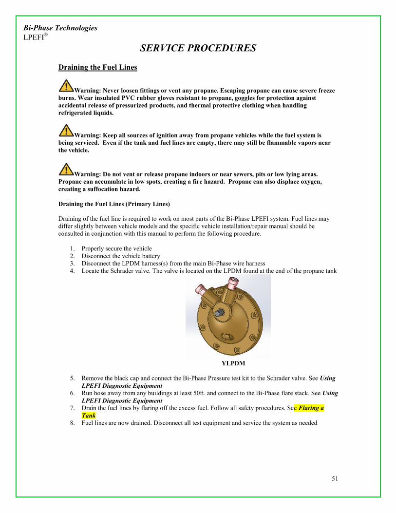
Bi-Phase Technologies LPEFI
SERVICE PROCEDURES
51
Draining the Fuel Lines
Warning: Never loosen fittings or vent any propane. Escaping propane can cause severe freeze burns. Wear insulated PVC rubber gloves resistant to propane, goggles for protection against accidental release of pressurized products, and thermal protective clothing when handling refrigerated liquids.
Warning: Keep all sources of ignition away from propane vehicles while the fuel system is being serviced. Even if the tank and fuel lines are empty, there may still be flammable vapors near the vehicle.
Warning: Do not vent or release propane indoors or near sewers, pits or low lying areas. Propane can accumulate in low spots, creating a fire hazard. Propane can also displace oxygen, creating a suffocation hazard. Draining the Fuel Lines (Primary Lines) Draining of the fuel line is required to work on most parts of the Bi-Phase LPEFI system. Fuel lines may differ slightly between vehicle models and the specific vehicle installation/repair manual should be consulted in conjunction with this manual to perform the following procedure.
1. Properly secure the vehicle 2. Disconnect the vehicle battery 3. Disconnect the LPDM harness(s) from the main Bi-Phase wire harness 4. Locate the Schrader valve. The valve is located on the LPDM found at the end of the propane tank
YLPDM
5. Remove the black cap and connect the Bi-Phase Pressure test kit to the Schrader valve. See Using LPEFI Diagnostic Equipment
6. Run hose away from any buildings at least 50ft. and connect to the Bi-Phase flare stack. See Using LPEFI Diagnostic Equipment
7. Drain the fuel lines by flaring off the excess fuel. Follow all safety procedures. See Flaring a Tank
8. Fuel lines are now drained. Disconnect all test equipment and service the system as needed

Bi-Phase Technologies LPEFI
SERVICE PROCEDURES
52
Draining the Fuel Lines (Transfer/Fill Lines)
Warning: All fill/transfer fuel lines connected to the fuel tank in the Bi-Phase System should be connected to a valve on the tank with a back-check to prevent fuel from the tank escaping when
draining hoses. Use extreme caution when draining fuel lines!
1. Place vehicle outdoors in a well ventilated area. Use a fan to help dissipate any escaping fuel 2. Properly Secure the vehicle 3. Disconnect battery 4. If disconnecting the transfer line disconnect the Aux. LPDM harness from the main harness 5. Ensure you are wearing proper protective equipment 6. Turn on a fan blowing onto the hose you intend to drain to help dissipate fuel 7. Using the proper size open end wrenches slowly crack the hose fitting to allow propane pressure to
gently release. (This should only take a minute or two) In the event fuel continues to vent for >5 minutes the system will need to be checked for a failed valve. See Draining the Fuel Tank for more information.
a. Transfer hose = 11/16” wrench b. Fill hose = 7/8” wrench
8. Once line is drained you may remove the hose and perform service as needed

Bi-Phase Technologies LPEFI
SERVICE PROCEDURES
53
Fuel Rail Removal Removal of the fuel rails may be necessary to service injectors. Please see Draining the Fuel Lines Removal of the loop hose or primary hose may not be necessary to service an injector. If fuel line removal is not necessary leave the hoses connected to the rails. If fuel rail removal from the line is necessary to perform repair/diagnostics please follow the following procedure. Removing the Fuel Lines (From Fuel Rail) There are (2) different types of connections that may be on the fuel rail depending on vehicle application. The two styles of fittings are shown below.
QD STYLE FITTING FLARE STYLE FITTING
Removing the hose (QD Style fitting):
1. Using compressed air remove any debris that may have built up in the QD fitting 2. Use a standard 3/8” QD fuel line disconnect tool to remove the fuel line
Common 3/8: QD Tools
3. Gently insert the QD tool into the rail 4. Gently push the tool until it is fully engaged and locking tabs are disengaged 5. Gently pull the fuel line outward using a slow twisting motion as you pull out 6. Place cap over fuel line/rail when not servicing part to prevent dirt/debris contamination
QD Style Connect Cutaway (removed)

Bi-Phase Technologies LPEFI
SERVICE PROCEDURES
54
Fuel Rail Removal (Cont’d)
Removing the hose (Flare Style fitting):
1. To remove the QD style hose connection you will need a 7/8” and 1” open ended wench 2. Using the 1” wrench place it on the brass male flare fitting inserted into the fuel rail. This will be
used as a “back-up” wrench to prevent the fitting turning inside the fuel rail
Back-Up Wrench
3. Place the 7/8” wrench onto the female flare fitting connected to the hose 4. While keeping the “back-up” wrench secure loosen the female fitting 5. Once all threads are disengaged gently pull outward to remove the inner line from the fuel rail 6. Place cap over fuel line/rail when not servicing part to prevent dirt/debris contamination
Flare Style Connect Cutaway (removed)
Fuel Rail Removal (Cont’d)
1. With fuel lines removed from fuel rail the rails can now be removed. 2. All LPEFI fuel rails utilize the OEM fuel rail mounting locations. Please reference all OEM
manufacturers’ torque values for re-installation. Consult Vehicle specific Installation Manual.
NOTE: Ford 6.8L 3valve V10 (2012-present) utilize a fuel rail mounting bracket that is first installed into the OEM fuel rail mounting locations. The fuel rails then mount to the newly installed bracket.

Bi-Phase Technologies LPEFI
SERVICE PROCEDURES
55
Removing the Fuel Lines (LPDM/YLPDM)
LPDM Exploded View YLPDM w/installed hoses
NOTE: Removal of the hose from the primary hose is not always necessary to perform service on internal components of the tank. If hose removal is not necessary leave hose attached to the LPDM and perform service as required. Removing the Fuel Lines (LPDM)
1. Disconnect the battery 2. Disconnect the LPDM harness from the Bi-Phase harness 3. Evacuate fuel lines of any fuel. See Draining the Fuel Lines 4. Spray penetrating oil onto the (2) screws that hold down the retaining plate 5. Using compressed air clear any debris from the screws 6. Carefully remove the screws from the LPDM 7. Remove the retaining plate, plate gasket, and split collars 8. Clean area around hose fitting with compressed air 9. Gently rotate the primary hose while simultaneously pulling outward on the hose 10. Once hose is removed install caps/covers over the LPDM and hose to prevent dirt
contamination
Removing the Fuel Lines (YLPDM)
1. Disconnect the battery 2. Disconnect the LPDM harness from the Bi-Phase harness 3. Evacuate fuel lines of any fuel. See Draining the Fuel Lines 4. Remove the red dust cap from the QD fitting 5. Using compressed air clear any debris from inside the QD fitting 6. Using a 3/8” QD fuel line tool insert the tool into the QD fitting
Common 3/8: QD Tools
7. Depress all 4 retaining clips with the QD tool 8. Gently pull the hose outward rotating the hose slowly 9. Once hose is removed cover QD fitting(s) with a cap to prevent dirt/debris contamination
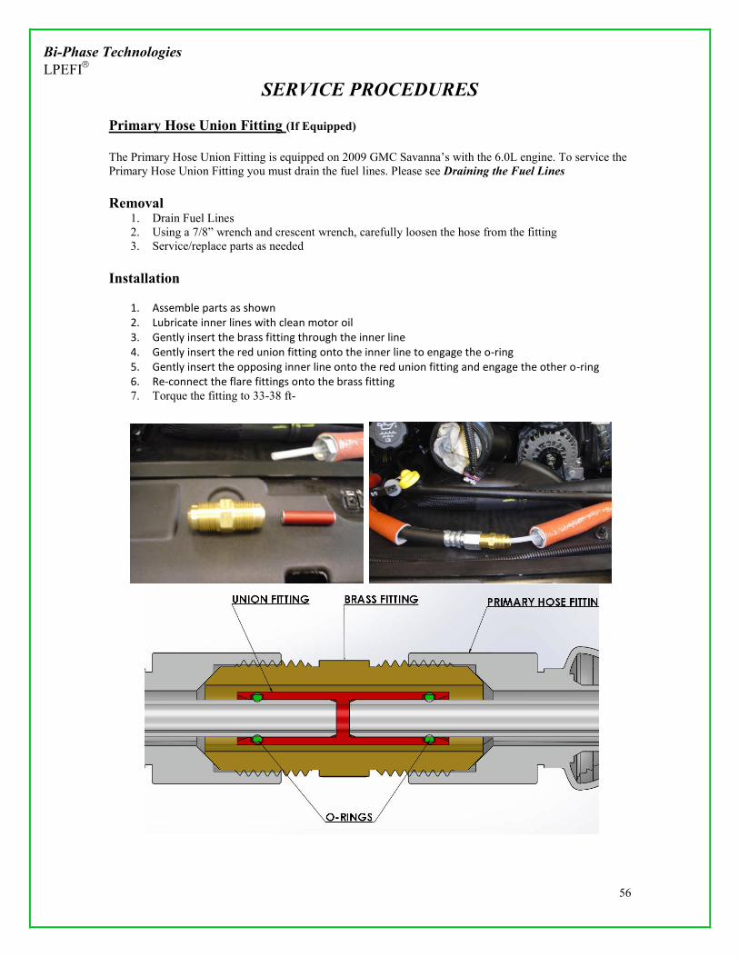
Bi-Phase Technologies LPEFI
SERVICE PROCEDURES
56
Primary Hose Union Fitting (If Equipped) The Primary Hose Union Fitting is equipped on 2009 GMC Savanna’s with the 6.0L engine. To service the Primary Hose Union Fitting you must drain the fuel lines. Please see Draining the Fuel Lines Removal
1. Drain Fuel Lines 2. Using a 7/8” wrench and crescent wrench, carefully loosen the hose from the fitting 3. Service/replace parts as needed
Installation
1. Assemble parts as shown 2. Lubricate inner lines with clean motor oil 3. Gently insert the brass fitting through the inner line 4. Gently insert the red union fitting onto the inner line to engage the o-ring 5. Gently insert the opposing inner line onto the red union fitting and engage the other o-ring 6. Re-connect the flare fittings onto the brass fitting 7. Torque the fitting to 33-38 ft-

Bi-Phase Technologies LPEFI
SERVICE PROCEDURES
57
Servicing the Wye (If Equipped) Note: The Wye is not used on the 7.4L GM engine and it has been eliminated on all models 2005 or newer. _____________________________________________________________________________________ The Wye is unserviceable and if there is a problem internally it should be replaced. To service the “Wye” you must drain the fuel lines. Please see Draining the Fuel Lines
Improperly attached fuel lines could cause the release of propane causing personal injury.
_________________________________________ Disconnect the Wye
1. To disconnect a hose from the Wye, you will need to disassemble the fitting and remove the two screws that hold the retaining cover plate of each hose individually
2. Pull the hose fitting out of the Wye carefully – do not lose the split collar retainers (note: kits are available that include the cover plate, gasket, screws and split collar retainers)
Connect the “Wye”
1. When installing the fuel lines, always work from the Wye – the nylon inner line is very sensitive in length and must be handled very carefully; not so much with the primary inner line
________________________________________
Warning: Improperly attached fuel lines could cause the release of propane causing personal injury.
_________________________________________

Bi-Phase Technologies LPEFI
SERVICE PROCEDURES
58
Disconnect the Wye (Cont’d)
2. Inner line length has been very critical in the past; the process to build this concentric line has
been validated and today the inner line length is not as much a problem; however, if you are servicing a vehicle and you are reinstalling the fuel lines, it is good to verify the length; as previously stated, always work from the Wye and measure the inner line at the opposite end; if there is less than 1.5” protruding from the metal hose end fitting. there could be a problem with inner line sealing
3. We recommend replacing the Wye if you expect a problem with the nylon inner line sealing or if there is a leak externally to the atmosphere
4. It is used as a “splitter” when two fuel injector rails are required; one port is the primary port or larger port and the two smaller ports are secondary ports for the fuel lines to each individual injector rail on each side of the engine
5. The Schrader Valve communicates with the supply fuel section of the system just as it does on the LPDM; this location is sometimes more convenient to perform the fuel pressure tests
6. See the illustration below

Bi-Phase Technologies LPEFI
SERVICE PROCEDURES
59
Installing Fuel Lines (YLPDM/LPDM)
________________________________________
Warning: Improperly attached fuel lines could cause the release of propane causing personal injury. Ensure all connections are properly installed!
_________________________________________
Installing Fuel Lines (LPDM):
1. Remove caps from LPDM/fuel line if present 2. Using a flashlight visually inspect the LPDM for any cut or miss-aligned O-rings 3. Insert the retaining plate and gasket onto the steel QD fitting on the primary hose 4. Lightly lubricate the QD fitting sealing surface and inner line with clean motor oil or O-lube
5. Center the white inner-line into the LPDM and gently engage the sealing o-ring onto the
inner-line 6. Gently insert the steel QD fitting into the LPDM by rotating the fitting in a twisting motion 7. Once QD fitting is almost seated insert the two locking collars around the fitting 8. Install the two screws through the retaining plate and gasket 9. Gently tighten screws until plate and gasket are seated flush
CORRECT WRONG – LOCKING RING EXPOSED!

Bi-Phase Technologies LPEFI
SERVICE PROCEDURES
60
Installing Fuel Lines (LPDM) (Cont’d)
10. Torque mark screws 11. Fuel line is now installed. Once system is ready to be pressure tested please see Leak
Checking the System Installing Fuel Lines (YLPDM):
YLPDM
1. Remove caps from fuel rail/fuel line if present 2. Inspect the QD fitting locking clip in the YLPDM to ensure it is not damaged 3. Using a flashlight visually inspect the QD fitting for any cut or miss-aligned O-rings 4. Inspect the red dust caps that come on the fuel line to ensure there are no rips or tears 5. Slide the caps into position over the fuel line fitting to be able to install once hose is installed
into the YLPDM
Pre-installed Dust Cap
6. Lightly lubricate the white nylon inner line and hose fitting with clean motor oil or o-lube
QD fitting/inner line

Bi-Phase Technologies LPEFI
SERVICE PROCEDURES
61
INSTALLING FUEL LINES (Cont’d)
7. Gently guide the white inner line into the QD fitting keeping it centered and straight as best as
possible
8. Once you feel the inner line engage the sealing o-ring gently push the hose fitting into the QD fitting until you hear an audible “click”. Gently pull on the line to ensure it is locked
9. Visually inspect with to ensure the 4 locking tabs engage the fitting properly. ( A small mirror
may be necessary)
Looking down into the QD fitting
10. Re-install the dust cap over the QD fitting 11. Fuel line is now installed. Once system is ready to be pressure tested please see Leak
Checking the System
________________________________________
Warning: Improperly attached fuel lines could cause the release of propane causing personal injury. Ensure all connections are properly installed!
_________________________________________

Bi-Phase Technologies LPEFI
SERVICE PROCEDURES
62
INSTALLING FUEL LINES (Cont’d)
Installing Fuel Lines (Flare Style fitting): ________________________________________
Warning: Improperly attached fuel lines could cause the release of propane causing personal injury. Ensure all connections are properly installed!
_________________________________________
1. Remove any dust caps on the fuel rail or hose 2. Using a flashlight inspect into the rail for any debris or miss-aligned O-rings 3. Inspect the flare fitting surfaces for any imperfections 4. Inspect the white inner line for any creases cuts or kinks 5. Lightly lubricate the white inner line with clean motor or O-Lube
White Inner Line
6. Center the white inner line with the fuel rail and gently insert the hose into the rail. Inner line will engage sealing o-ring. Use extreme care when seating inner line into fuel rail o-ring
Insert Hose into Rail
7. Hand thread the female flare fitting on the hose onto the male flare fitting on the rail 8. Once tight use a 7/8” and 1” wrench to tighten fitting. 1” is used as a “back-up” wench to
prevent fitting from turning inside the rail. 9. Torque fitting to 33-38ft-lbs 10. Fuel line is now installed. Once system is ready to be pressure tested please see Leak
Checking the System _________________________________________
Warning: Improperly attached fuel lines could cause the release of propane causing personal injury. Ensure all connections are properly installed!

Bi-Phase Technologies LPEFI
SERVICE PROCEDURES
63
_________________________________________ INSTALLING FUEL LINES (Cont’d)
Installing Fuel Lines (QD Style):
QD Style Connect Cutaway (removed)
The following procedure includes installation instruction for the following types of hoses
Loop hoses on all makes/models Vehicles equipped with YLPDM
1. Remove caps from fuel rail/fuel line if present 2. Inspect the QD fitting locking clip in the YLPDM to ensure it is not damaged 3. Using a flashlight visually inspect the QD fitting for any cut or miss-aligned O-rings 4. Inspect the red dust caps that come on the fuel line to ensure there are no rips or tears
(YLPDM) 5. Slide the caps into position over the fuel line fitting to be able to install once hose is installed
(YLPDM)
Pre-installed Dust Cap
6. Lightly lubricate the white nylon inner line and hose fitting with clean motor oil or o-lube
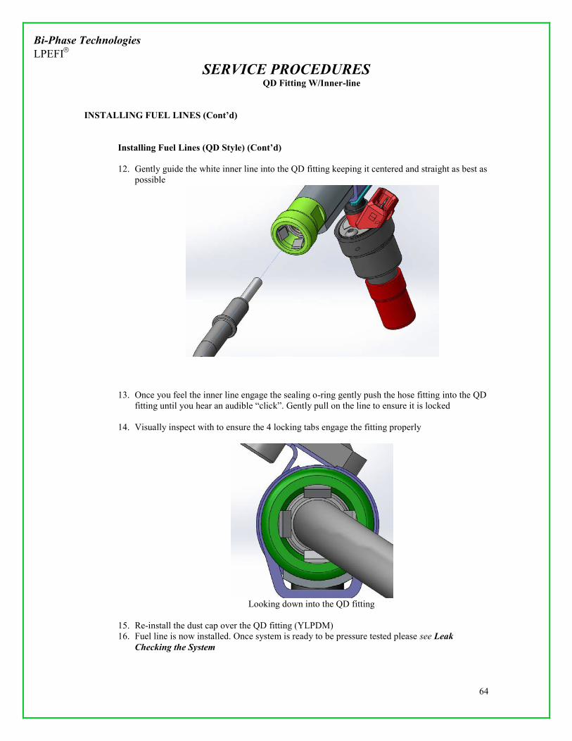
Bi-Phase Technologies LPEFI
SERVICE PROCEDURES
64
QD Fitting W/Inner-line
INSTALLING FUEL LINES (Cont’d)
Installing Fuel Lines (QD Style) (Cont’d)
12. Gently guide the white inner line into the QD fitting keeping it centered and straight as best as
possible
13. Once you feel the inner line engage the sealing o-ring gently push the hose fitting into the QD fitting until you hear an audible “click”. Gently pull on the line to ensure it is locked
14. Visually inspect with to ensure the 4 locking tabs engage the fitting properly
Looking down into the QD fitting
15. Re-install the dust cap over the QD fitting (YLPDM) 16. Fuel line is now installed. Once system is ready to be pressure tested please see Leak
Checking the System
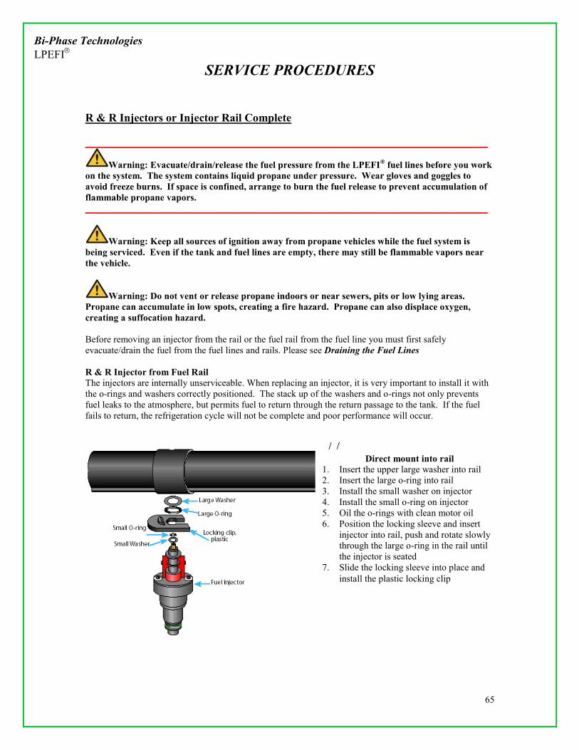
Bi-Phase Technologies LPEFI
SERVICE PROCEDURES
65
R & R Injectors or Injector Rail Complete _____________________________________________________________________________________
Warning: Evacuate/drain/release the fuel pressure from the LPEFI® fuel lines before you work on the system. The system contains liquid propane under pressure. Wear gloves and goggles to avoid freeze burns. If space is confined, arrange to burn the fuel release to prevent accumulation of flammable propane vapors. _____________________________________________________________________________________
Warning: Keep all sources of ignition away from propane vehicles while the fuel system is being serviced. Even if the tank and fuel lines are empty, there may still be flammable vapors near the vehicle.
Warning: Do not vent or release propane indoors or near sewers, pits or low lying areas. Propane can accumulate in low spots, creating a fire hazard. Propane can also displace oxygen, creating a suffocation hazard. Before removing an injector from the rail or the fuel rail from the fuel line you must first safely evacuate/drain the fuel from the fuel lines and rails. Please see Draining the Fuel Lines R & R Injector from Fuel Rail The injectors are internally unserviceable. When replacing an injector, it is very important to install it with the o-rings and washers correctly positioned. The stack up of the washers and o-rings not only prevents fuel leaks to the atmosphere, but permits fuel to return through the return passage to the tank. If the fuel fails to return, the refrigeration cycle will not be complete and poor performance will occur.
Direct mount into rail 1. Insert the upper large washer into rail 2. Insert the large o-ring into rail 3. Install the small washer on injector 4. Install the small o-ring on injector 5. Oil the o-rings with clean motor oil 6. Position the locking sleeve and insert
injector into rail, push and rotate slowly through the large o-ring in the rail until the injector is seated
7. Slide the locking sleeve into place and install the plastic locking clip

Bi-Phase Technologies LPEFI
SERVICE PROCEDURES
66
R & R Injector from Fuel Rail, cont’d
Extended mount, 8.1L G.M. 1. Install the large washer into the rail 2. Install the large o-ring into the rail 3. Install the large washer into the injector end of
tube assembly 4. Install the large o-ring into the injector end of
tube assembly 5. Install the small washer on the injector 6. Oil all o-rings with clean motor oil 7. Install the injector into the tube assembly, slowly
push and rotate injector into tube assembly until it is seated and install locking clip
8. At the rail end of the tube pull the inner rubber tube out to extend past the end of the metal tube, pull it out slightly
9. With the locking sleeve in position insert the injector tube assembly into the rail, slowly pushing and rotating until it is seated
10. Push the sleeve into locking position and install the plastic locking clip

Bi-Phase Technologies LPEFI
SERVICE PROCEDURES
67
Injectors, cont’d Injector Insulator Housing The injectors are internally unserviceable; however the insulator housing covers the injector and could require replacement. The injector insulator housing should be leak free of vacuum leaks or should hold a vacuum. Before installing the injector rail on an engine, check each injector for vacuum leaks. This is done by using a hand held (Mighty Vac) vacuum pump. Push the vacuum hose on the injector insulator housing tip and pump the vacuum pump to 18”Hg to 28”Hg. If it holds a vacuum, it is sealed and does not need any service. If it does not hold a vacuum, repair/replace the insulator housing and/or o-ring or o-rings.
If freezing occurs on the insulator housing this is an indication the insulator housing is leaking or has a vacuum leak. Check the insulator housing for cracks and replace as necessary. Always check injectors for a vacuum tight seal before installing. NOTICE: Q4 2013: Ford 5.4L rails/injectors come installed with injector retaining clip as shown
18” to 28” Hg Should hold vacuum
Top o-ring sealing
Injectors built after June 2002 use a lower sealing o-ring in addition to the top o-ring

Bi-Phase Technologies LPEFI
SERVICE PROCEDURES
68
Injectors, cont’d Injector Electrical The injector is designed to mimic a gasoline injector. Therefore the injector coil resistance is similar to a gasoline injector. The nominal resistance across the electrical connectors should be 12.6 to 13Ω ohms. An acceptable range is 12Ω to 15Ω, but not to exceed 2Ω between the lowest reading injector to the highest reading injector. If there is greater than 2Ω difference, choose and replace the highest or lowest resistance injector, whichever corresponds, to achieve a range inside 2Ω. If the resistance test proves an open circuit, the injector must be replaced. Injector harness The injector electrical connectors should be facing outward to allow clearance between injector & intake plenum. The electrical connector could interfere with the installation of the rail or the installation of the rail could damage the injector if not pre-positioned outward. Note: Always be aware of routing of the harness. Do not route over the top of the fuel rail.

Bi-Phase Technologies LPEFI
SERVICE PROCEDURES
69
LPDM (Liquid Propane Delivery Module)
Servicing the LPDM (Liquid Propane Delivery Module) The LPDM is not serviceable. If a problem develops with the LPDM it should be replaced. The LPDM is a concentric design like the fuel lines and fuel rails. It provides 100% closure of fuel flow through the normally closed internal fuel supply valve and fuel return valve. When electrically energized the valves are two-stage opening allowing pressure to equalize to both sides of the valve before completely opening. This prevents higher amperage spikes in the 12-volt solenoid used to open the valve. Both valves are equipped with excess flow valves to prevent excessive flow of fuel in the case of fuel line/hose failure in an accident. As mentioned previously, the valves are normally closed and would close immediately upon engine failure, voltage failure or in an accident that disconnected the fuel line. Inside the tank, the condenser (if applicable), scavenge pump (if applicable) and the fuel pump connect to the LPDM. (Condenser removed starting in 2005 MY) Please see Scavenge Pump for more information on Scavenge Pump service.

Bi-Phase Technologies LPEFI
SERVICE PROCEDURES
70
YLPDM (2012)
YLPDM Servicing the YLPDM (Wye Liquid Propane Delivery Module) The YLPDM is a newly designed brass delivery module that is very similar to the original LPDM. The YLPDM has all of the same components as the LPDM internally, but has a dual outlet as opposed to a single outlet. The hoses connect to the YLPDM and fuel rails using a standard type 3/8” QD fitting that is found on many OEM gasoline systems. The loop hose found on many LPEFI systems uses the same connections. The YLPDM is not serviceable. If a problem develops with the YLPDM it should be replaced. The YLPDM is a concentric design like the fuel lines and fuel rails. It provides 100% closure of fuel flow through the normally closed internal fuel supply valve and fuel return valve. When electrically energized the valves are two-stage opening allowing pressure to equalize to both sides of the valve before completely opening. This prevents higher amperage spikes in the 12-volt solenoid used to open the valve. Both valves are equipped with excess flow valves to prevent excessive flow of fuel in the case of fuel line/hose failure in an accident. As mentioned previously, the valves are normally closed and would close immediately upon engine failure, voltage failure or in an accident that disconnected the fuel line. Inside the tank, the condenser (if applicable), scavenge pump (if applicable) and the fuel pump connect to the LPDM. (Condenser removed starting in 2005 MY) Please see Scavenge Pump for more information on Scavenge Pump service.

Bi-Phase Technologies LPEFI
SERVICE PROCEDURES
71
Auxiliary LPDM (Liquid Propane Delivery Module) (Secondary Tanks)
The Auxiliary LPDM looks very similar to a conventional LPDM. Earlier versions will be a blue aluminum casting. Newer Auxiliary LPDM’s will be a brass casting. The Auxiliary LPDM bolts onto an auxiliary fuel tank to move fuel from the auxiliary tank into the main fuel tank that powers the vehicle. It is equipped with 1 solenoid valve and pump. The Auxiliary LPDM has only 2 wires going into the assembly vs. the 4 wires on the LPDM and YLPDM. Servicing the Auxiliary LPDM (Liquid Propane Delivery Module) The Auxiliary LPDM is not serviceable. If a problem develops with the LPDM it should be replaced. It provides 100% closure of fuel flow through the normally closed internal fuel supply valve. As mentioned previously, the valves are normally closed and would close immediately upon engine failure, voltage failure or in an accident that disconnected the fuel line. Inside the tank, the fuel pump connected to the LPDM. The LPDM is secured to a tank flange by 8 bolts. The bolts are special aluminized bolts and should not be reused. Anytime the LPDM is removed for other tank service, a new o-ring and new bolts should be used.

Bi-Phase Technologies LPEFI
SERVICE PROCEDURES
72
Removing the LPDM (LPDM, YLPDM, Aux.LPDM)
1. Evacuate the fuel lines and tank completely. See Draining the Fuel Lines 2. Remove fuel line from LPDM (if necessary. Service to internal tank components do not
always require the removal of the fuel line from the LPDM. If removal is necessary see Removing the Fuel Lines
3. Mark the orientation of the bulkhead with tape or chalk – this will help you orient the hose port correctly when reinstalling
4. Loosen the 8 LPDM flange bolts evenly in a crisscross pattern 5. Remove all of the bolts completely 6. Pull the LPDM assembly away from the flange slightly and disconnect the condenser hose (if
applicable) from the fuel return valve, no hose clamp is used on this hose 7. The condenser can be removed by unclipping it from the bottom of the tank; removing it is
not necessary other than to inspect it and the condition of its hose (if applicable) 8. Reach into the tank to access the fuel pump and unclip the clip that holds the fuel pump and
filter down inside the pump cup; the clip fits through two holes in the fuel pump cup a. NOTE: Old clip designs did not attach permanently to the pump cup so they were
easy to drop inside the tank. A newer clip design allowed one side of the clip to stay attached to the pump cup. Simply unhook one side and swing the clip over to the opposite side of the pump cup. This helped to prevent dropping the clip inside the tank. It is not necessary to disconnect the electrical connector from the fuel pump to remove the hold down clip; however some may find this step makes it easier. Remember, if you disconnect the connector, it must be reconnected when reinstalling the pump and LPDM
9. If a scavenge pump is present disconnect the Scavenge Pump electrical connectors. Mark each connection with a marker or tape to ensure proper re-installation. Please reference the Scavenge Pump section in this manual for more information.
10. Once the fuel pump is unclipped and the condenser/scavenge pump is disconnected(if applicable), you can remove the LPDM assembly by lifting out the fuel pump, and then whatever service is necessary can be performed
Pump hold down clip & locating cup
Condenser hose, no clamp
The condenser and bi-pass valve has been eliminated on 2005 and newer models
The condenser and bypass valve have been eliminated on 2005 and newer models

Bi-Phase Technologies LPEFI
SERVICE PROCEDURES
73
Remove the LPDM, cont’d
11. If the LPDM is going to be out of the tank for any length of time cover the opening/flange on the tank; use duct tape or a prepared cover that can be bolted into place utilizing the sealing o-ring; it is important to keep air, dirt and moisture out of the fuel tank
Reinstalling the LPDM Clean inside of tank before reinstalling LPDM. Take a clean rag and wipe the inside of the tank within an arm’s reach. If tanks contains excess containments (i.e. sludge, metal flakes) tank should be removed and cleaned. Contact your local propane company for proper cleaning procedure. Visually inspect valves on the inside of the tank for any immediate signs of corrosion or problems. Replace if necessary.
1. Inspect the wires, hoses, hose clamps to be certain everything is connected properly 2. Clean the O-ring gland on the tank. Install the new O-ring into the o-ring gland on the tank 3. Lift the LPDM with one hand, hold the fuel pump with the other hand 4. Guide the pump into the tank opening and place the fuel pump into its locating cup 5. Install the fuel pump hold down clip 6. Confirm the condenser (if equipped) is secured in place by the securing clips in the bottom of
the tank 7. Connect the condenser hose to the LPDM fuel return valve, no clamp is required on this hose
connection 8. If the vehicle is equipped with a scavenge pump ensure pump is secured wiring is properly
connected. See Scavenge Pump 9. Make sure all hoses and wiring is pushed inside the tank with no kinks or sharp bends, push
the LPDM assembly over the opening in the tank and clock it the same way it was when it was removed; be careful with the o-ring, it must be in the o-ring gland or the LPDM will pinch it and cause a fuel leak when the tank is refilled with fuel
10. Install the new aluminized coated bolts that came with the new o-ring and hand tighten (note: anti-seize compound is not necessary with these aluminized coated bolts, but not prohibited)
11. A deep well 3/8” 12-point socket is required to tighten the bolts 12. Tighten the bolts evenly, a little at a time
Cover the opening

Bi-Phase Technologies LPEFI
SERVICE PROCEDURES
74
Reinstalling the LPDM (Cont’d)
13. Finish tightening the bolts in the order shown below, or in a crisscross pattern; torque the bolts to 20-25 foot pounds
LPDM YLPDM AUX. LPDM NOTE: Latest versions of LPDM, YLPDM, and Aux. LPDM are brass castings. (2013) 14. Torque mark all bolts with a paint pen 15. If removed re-install the fuel lines. See Installing the Fuel Lines
Bypass Valve Removal The bypass valve that is located in the fuel hose between the supply solenoid on the LPDM and the fuel pump is no longer needed. Functionally, without the bypass valve, LPDM assembly will operate in the same fashion.
1. Drain the fuel tank, fuel lines, and fuel rails. See Draining a Tank, Draining the Fuel Lines for proper procedures
2. Remove the LPDM from the tank. See Removing the LPDM 3. Remove the two hose clamps that connect the fuel line from the pump to the bypass valve 4. Remove the two hose clamps that connect the fuel line from the bypass valve to the supply valve 5. Remove the old fuel line and bypass valve and dis-guard 6. Install new fuel line and pump to the LPDM with the new hardware 7. Cover wire harness with .25” diameter split loom 8. Zip tie wire harness to fuel line with 3 zip ties 9. Re-install all components. See Installing the LPDM

Bi-Phase Technologies LPEFI
SERVICE PROCEDURES
75
LPDM W/Bi-pass Valve LPDM W/Bi-pass Removed The Scavenge Pump
The Scavenge pump is an auxiliary pump installed inside the fuel tank designed to keep fuel in the well near the primary fuel pump during extreme vehicle angles/maneuvers. It also is helps to obtain maximum fuel usage in LPG tanks due to the constrictions on tank designs and sizes. The Scavenge pump is a 12v pump that runs off of the Supply Valve in the system. The pump is wired in a parallel format with the supply valve and will run whenever the supply valve is on. Systems with a scavenge pump wire the supply valve/scavenge pump circuit through an externally mounted relay near the primary pump relay. (Please see specific vehicle wiring harness schematic for details) When diagnosing the scavenge pump electrically you observe the amp meter with the 3 switch box. Amperage over the supply valve circuit with scavenge pump should be within spec below. Scavenge Pump & Supply Valve – 2- 4 Amps Scavenge Pump Wiring Schematic (Internal)

Bi-Phase Technologies LPEFI
SERVICE PROCEDURES
76
The Scavenge Pump (Cont’d) Scavenge Pump 2012-2014 GM 610
Scavenge Pump 2012-2014 GM 610
The Scavenge pump in 2012-2014 GM Savanna’s have a scavenge pump that mounts to the fuel pump “cup” that houses the main fuel pump. It connects to a tube welded into the fuel tank. The tube runs the length of the tank to pull fuel from the opposite end of the tank when in a steep nose high situation. The pump attaches to the tube via a small flex hose that should be replaced whenever the scavenge pump is serviced. The pump is mounted to a small bracket via a worm gear clamp. The bracket is attached to the fuel pump cup via a large worm gear clamp. To Service Scavenge the tank must first be drained, and LPDM removed. See Removing The LPDM

Bi-Phase Technologies LPEFI
SERVICE PROCEDURES
77
The Scavenge Pump (Cont’d) Scavenge Pump 2010-2011 Ford E450
Scavenge Pump 2010-2011 Ford E450
The Scavenge pump in 2010-2011 Ford E450’s have a scavenge pump that mounts to the fuel tank baffle tube inside the tank. The pump mounts using two clips and 2 tie-wraps. The Scavenge pump on 2010-2011 Ford E450’s are only equipped on vehicles that have a saddle tank that has one cylinder on the outside of the driver’s side frame connected by tubes to an additional cylinder on the inside of the driver’s side frame. The green fuel line draws fuel form the opposite side of the baffle as well as from the inside cylinder. An “Auxiliary pump identification sticker” is installed on the inside driver’s side door jam on Ford E450’s equipped with this kit. Please see specific service bulletin for more information Servicing the Scavenge pump The Scavenge pump is specifically designed to work with the Bi-Phase LPEFI components and should be replaced with a pump provided only from Bi-Phase Technologies.
1. To Service Scavenge the tank must first be drained, and LPDM removed. See Draining a Tank;
Removing The LPDM 2. Once all fuel is evacuated and LPDM/Pump is removed you may remove the Scavenge pump.
a. GM SAVANNA: i. Disconnect green flexible fuel line from the scavenge pump to internal tube.
(discard) ii. Using a small Phillips screwdriver loosen the worm gear clamp around the main
Fuel pump mounting Cup iii. Gently lift up on the pump/bracket assembly and pull out of the tank. iv.
b. FORD E450: i. Disconnect green flexible fuel line from the scavenge pump to internal tube.
Remove all brass fittings attached to fuel line Discard remaining green fuel line ii. Cut tie-wraps around fuel pump
iii. Pull pump and two clips out of the tank and perform service as needed

Bi-Phase Technologies LPEFI
SERVICE PROCEDURES
78
Servicing the Scavenge pump (Cont’d)
3. When servicing the scavenge pump replace any flexible fuel line 4. Use new mounting hardware when re-installing scavenge pump 5. Install Scavenge pump as directed below. For more detailed information please contact Bi-Phase
Technologies
a. 2012-2014 GM SAVANNA:
i. Install Scavenge pump onto scavenge pump bracket outside of the tank with pump discharge facing toward the LPDM
ii. Loosely install hose clamp onto scavenge pump bracket to be attached to fuel pump cup
iii. Gently insert scavenge pump and bracket into tank iv. Place previously installed worm gear clamp over the primary pump cup v. Using a small socket driver tighten the hose clamp
vi. Connect green flexible fuel hose from scavenge pump inlet barb fitting onto the barb fitting connected to the suction tube inside the tank
vii. Connect all wiring according to the diagram shown on page 74. Install split loom over loose wires and secure
viii. Ensure all wiring and hoses are secured in a way to prevent chaffing ix. Install LPDM/YLPDM
b. 2010-2011 FORD E450:
i. Install Scavenge pump onto scavenge pump brackets outside of the tank with pump discharge facing toward the LPDM
ii. Install the new fuel hoses/fittings onto the inlet of the scavenge pump. Secure with hose clamp
iii. Install hoses into tank as shown in schematic. (See page 76) iv. Install pump/clamp assembly into tank onto the slosh tube ensuring pump rests
on top of the tube and against the tank wall v. Secure pump with 2 large tie wraps
vi. Connect all wiring according to the diagram shown on page 74. Install split loom over loose wires and secure
vii. Ensure all wiring and hoses are secured in a way to prevent chaffing viii. Install LPDM/YLPDM

Bi-Phase Technologies LPEFI
SERVICE PROCEDURES
79
Servicing the Scavenge pump (Cont’d) 2010-2011 FORD E450 SCAVENGE PUMP SCHEMATIC (SADDLE STYLE TANK)

Bi-Phase Technologies LPEFI
SERVICE PROCEDURES
80
Replacing the Fuel Pump _____________________________________________________________________________________
Warning: The fuel pump assembly may contain liquid propane. At cold temperatures the hose may contain liquid propane. Wear insulated PVC rubber gloves and goggles to prevent freeze burns or injuries. _____________________________________________________________________________________
1. Drain the tank and remove the LPDM. See Draining a Tank and Removing the LPDM 2. Disconnect the electrical connector from the top of the pump 3. Cut any zip ties connecting the wire harness to the fuel line 4. Remove the hose from the supply valve on the LPDM by loosening the worm gear clamp 5. Carefully remove the hose 6. Remove the old pump/filter, hose and brass bypass valve (Eliminated in 2005) 7. Install new fuel pump into new fuel filter. Secure with filter retaining clip
8. Install the new fuel line onto the fuel pump 9. Install new hose clamp as shown. (Ensure clamp screw faces away from the electrical
connector to ensure pump clip inside tank will install properly
Correct Install Incorrect Install
10. Reinstall the new fuel pump/filter and connect the fuel supply hose from the fuel pump to the LPDM supply valve (the supply valve is always the valve closest to the hose port or directly inline/behind the Schrader Valve) Secure with new worm gear clamps
11. Inspect all electrical wires/connectors for signs of wear/improper connection. Replace components if necessary
12. Connect the wiring harness to the fuel pump 13. Install split loom over pump wires 14. Tie-wrap pump wires to the fuel hose every 4” 15. Tighten all the hose clamps and prepare to reinstall the LPDM (See Installing LPDM)

Bi-Phase Technologies LPEFI
SERVICE PROCEDURES
81
Purging the Tank _____________________________________________________________________________________
Warning: Purge the tank outdoors in the open, away from buildings, other vehicles, electrical devices, gas appliances, and other sources of ignition. Disconnect the electrical connection from the tank control box and disconnect the battery to avoid ignition inside the tank. Any spark or flame can ignite a cloud of propane vapor in or near the tank which could cause severe burns, personal injury and/or property damage. Always disconnect the negative battery terminal first. _____________________________________________________________________________________ Purging the tank is different from the purge cycle in the LPEFI system. Purging the tank means removing the air (oxygen) and moisture from inside the tank before putting the tank into service. This is a required procedure on all new tanks (tanks that have never been filled with propane) or tanks that have been evacuated and opened to the atmosphere for service or for any reason. Purging the tank is accomplished by injecting a very small amount of propane into the tank, then flaring/venting off the fuel/air mixture to remove any air trapped inside the tank. Note: Purging the tank is always required if the tank is evacuated and any valve or component is removed that causes the tank to be exposed to the atmosphere. Why Purge a Tank? Most tanks are steel and are prone to rust. To prevent rust, purging will remove air (oxygen) and moisture which causes rust. Also, by purging and removing the air (oxygen) from the tank there is no chance of air in the tank causing pressure fluctuations. This trapped air could also cause excess pressure in the tank and could cause a slow fill situation. New tanks come purged with an inert gas and this same situation could also occur if the inert gas is not purged from the tank. Always follow proper purge procedures. The LPEFI system uses an electric fuel pump mounted inside the tank. Propane must be mixed with air between 2.15% and 9.6% fuel to air mixture to be combustible or flammable. If not purged, a spark from the electric fuel pump could ignite such a mixture. Fortunately, this combustible mixture is seldom found inside a tank and by purging the tank prior to filling or refilling, the tank will prevent the air/fuel mixture from ever reaching a combustible mixture.
Warning: Purge the tank in the outside, at least 25 feet from any building. Propane vapors should be flared off whenever possible. When venting outside is not possible attach an approved hose to burn/vent propane vapors safely You can perform the purge with the tank installed on the vehicle. You should not connect any electrical connectors to the tank after service or before filling a new tank. If the tank is connected electrically, DISCONNECT it from the tank control box and disconnect the vehicle battery (always disconnect the negative terminal first). It is also recommended that the tank be grounded to earth ground with a cable (like a battery jumper cable) to prevent sparks due to static electricity. At this point all replaced components should be installed and tightened to specification. The following procedures or method is approved by the United States National Propane Gas Association (NPGA). For more information you can go to their website at www.npga.org.

Bi-Phase Technologies LPEFI
SERVICE PROCEDURES
82
Purging the Tank (Cont’d)
1. Secure the vehicle 2. Remove the brass cap from the vapor service valve on the tank you want to purge (The tank
should not have fuel at this time (it should be totally evacuated) 3. The propane vapor used can be a small cylinder, such as a barbeque grill cylinder. These cylinders
are vapor service only. Attach an adjustable high pressure regulator to the cylinder and adjust the outlet pressure of the regulator to 15 p.s.i. (this is to be connected to vapor service only)
4. Using an approved LPG hose connect the propane source to the tank through the Liquid Service Valve (See Tank Valves)
5. Connect hose and flare stack to the 80% liquid level valve. (See Flaring a Tank)
Note: When purging a tank you want to use the valve that is in the highest location in relation to the ground level. (80% fixed level gauge aka the Spitter Valve) Propane vapor is heavier that air and will settle below air inside the tank. When pressure is released the air near the top of the tank will be purged out 6. Ensure all valves on the tank are closed 7. Open the valve on the fuel tank in which the propane source is connected to 8. Slowly open the vapor service valve on the cylinder and allow vapor pressure to equalize into the
tank being purged to15 p.s.i. and turn off the valves 9. Close all valves 10. Release all the pressure in the tank being using a flare stack to burn off propane vapors, or release
to the atmosphere if flaring is not possible. 11. Once all pressure is removed close the valves 12. Repeat steps 7-11 (4-5) times to ensure air is removed
Note: If there is any indication of moisture or water in the tank it is a good idea to inject some methanol into the tank before filling the tank with fuel. On average, one pint of methanol per 100 gallons of propane or 1 gallon of methanol per 1,000 gallons or propane will resolve any moisture or water residue. 13. On the last purge with vapor, leave the tank being purged pressurized 14. The purge process is now complete and you may fill the tank 15. Fill the tank with 5 gallons of fuel before any electrical components are reconnected
Connecting to a service valve is also allowable
Install high pressure regulator 0 to 30 p.s.i. here and adjust to 15 p.s.i.
Small vapor service propane cylinder, like a barbeque grill cylinder
Release purging pressure to atmosphere in a safe manner from a service valve located close to the top of the tank, repeat purging procedure 3 to 5 times

Bi-Phase Technologies LPEFI
SERVICE PROCEDURES
83
Purging the Fuel Transfer System (Dual Tank Applications) After installation/repair of a transfer system the transfer hose must be purged in order for the transfer system to operate properly. If a transfer hose has a pressure difference from the propane tank that is too great it will cause the “excess flow” valve in the LPDM to trip; thus restricting fuel flow out of the Secondary LPDM to a .054” orifice. The valve will reset once the valve is closed for 2-5 seconds. Follow the following steps after installing or servicing a vehicle fuel transfer system
1. Secure the Vehicle 2. Disconnect the vehicle Battery 3. Disconnect the Secondary LPDM wire harness from the main LPEFI harness 4. Ensure there is adequate fuel in the Secondary tank ( >1/2 tank recommended) 5. Check transfer line for proper installation/torque mark 6. Check 80% stop fill valve on the primary tank to ensure valve is oriented correctly
a. Valve is stamped on the front face with the word “Top” b. Follow transfer hose from Secondary LPDM to Primary tank
7. Connect the “3 switch box” to vehicle 12v. 8. Ensure all switches are in the “off” position 9. Connect auxiliary connection onto the secondary LPDM harness 10. Turn on the Pump Switch on the “3 switch box” for 15-20 seconds 11. Turn off the Pump Switch for a minimum of 15-20 seconds 12. Repeat steps 8-9 (5) times 13. Check transfer hose connection points for any leaks. Fix any leaks if found and go back to step 8 14. Once transfer system has no leaks system is purged 15. Re-connect all harness connections and the battery NOTE: The transfer line connects to an automatic 80% stop fill valve on the primary tank and depending on fuel level in the primary tank; it may not allow fuel to enter the tank from the transfer hose. In the event the primary tank is full the pump amperage will be abnormally high due to the pump pushing against a closed 80% stop fill valve.

Bi-Phase Technologies LPEFI
SERVICE PROCEDURES
84
Drain/Evacuate the Tank for Service To service internal components of the tank you must first drain/evacuate a tank of all its fuel and vapor pressure. There are 3 ways to evacuate/drain a fuel tank
1. Use the fuel in the tank (Will require evacuation of vapor pressure) 2. Transfer the fuel to an empty tank (Will require evacuation of vapor pressure) 3. Burn the fuel through a flare stack
NEVER release propane to the atmosphere where conditions would not permit:
1. The volume required to be released is excessive (> 1 gallon of liquid ) 2. Where there are buildings, structures in close quarters 3. When there is no wind to dilute the releasing fuel to a noncombustible limit of flammability
It is never recommended to release to the atmosphere. In all cases when it is necessary to release fuel to the atmosphere all sources of ignition, clearances and wind condition must be considered. It is recommended if you cannot transfer the fuel to an empty tank that you burn the fuel through a flare stack, as previously mentioned. _____________________________________________________________________________________
Warning: Never service a tank inside a building. Always perform the evacuation procedures outside with a minimum of 25 feet of clearance from any combustibles, buildings, structure, or any source of ignition. Always remove any possible sources of ignition when performing the evacuation. When venting a tank flare off the propane vapors whenever possible. If required to release fuel to the atmosphere, do so with the utmost of safety and give consideration to such factors as distance to buildings, terrain, wind direction and velocity, and use of a vent stack so that a flammable mixture will not reach a point of ignition. The person(s) or company performing any fuel transfer or service work on a propane system is liable for their actions and must be properly trained, insured and licensed if required by the authority having jurisdiction. The National Fire Protection Associations pamphlet No. 58 states in Chapter 1, “General Provisions 1-5 Qualification of Personnel: Persons who transfer liquid LP-Gas, who are employed to transport LP-Gas, or whose primary duties fall within the scope of this code shall be trained in proper handling procedures. Refresher training shall be provided at least every three years. The training shall be documented.” For more information, contact your local, state or national propane gas association and ask about certified employee training programs. For more information on NFPA or to order the LP-Gas Code Handbook, call NFPA at 1-800-344-3555 or visit their website at www.nfpa.org. _____________________________________________________________________________________

Bi-Phase Technologies LPEFI
SERVICE PROCEDURES
85
Transferring Fuel to Auxiliary Tank
Danger: Propane is stored under pressure. Do not remove any valves, bulkheads or fittings from a propane tank unless the tank has been properly drained (evacuated) completely. Failure to do so may result in severe personal injury or death. Please contact your local propane provider or Bi-Phase Technologies to assist with evacuating a tank
Danger: Always wear proper safety equipment when working on any part of the propane system. Always wear insulated propane resistant gloves, aprons, jackets, pants, shoes, and goggles. Failure to do so may result in severe bodily injury or death. The following procedure will take you through transferring liquid propane from one tank into another without using any pumps but rather by using pressure differentials to move fuel. The concept is to lower the pressure of the tank that is receiving fuel. This is achieved by flaring the vapor pressure and thus lowering the tanks internal pressure. A transfer hose is connected between the tanks Liquid Service Valves. With the pressure lower in the receiving tank, the higher pressure in the tank that you are looking to drain will push the liquid propane into the lower pressure receiving tank. Please note this process will not evacuate a tank completely but rather drain most of the liquid from a tank to be re-used. To fully evacuate a tank you must flare off all remaining pressure from the tank. See Flaring a Tank for more information. Please follow all Federal, State, or Local laws that apply. Contact your local propane provider or Bi-Phase Technologies to assist with evacuating a tank
1. Secure the vehicle 2. Ensure an approved fire extinguisher is present 3. Disconnect the Battery 4. Disconnect the LPDM wire harness from the Bi-Phase harness 5. Be sure the liquid and vapor service valves are closed and remove the brass cap – if a service
valve hand wheel handle is missing, replace it for this service procedure 6. Connect the Liquid valve of the tank to be drained to the Liquid valve of the receiving tank using
the Bi-Phase transfer hose or other approved LPG hose. See Tank Valves and Bi-Phase Test Equipment for more information.
7. Connect the vapor burner/flare to the 80% fixed level valve on the receiving tank using the Bi-phase flare kit or other approved LPG hose. See Tank Valves and Bi-Phase Test Equipment for more information.
8. Secure vapor burner/flare a minimum of 25ft. away from any object

Bi-Phase Technologies LPEFI
SERVICE PROCEDURES
86
Transferring Fuel to Auxiliary Tank (Cont’d)
9. Slowly open the Liquid Service Valve on the receiving tank until fully opened 10. Slowly open the Liquid Service valve on the tank that is to be drained (Fuel will begin to transfer.
Open the valve slightly to pressurize system and allow pressure to check for leaks) 11. Check all connections for leaks with approved leak detector 12. If no leaks are found slowly open the Liquid Service Valve of the tank that is to be drained as far
as possible without tripping the excess flow valve a. The Liquid service valve is equipped with an excess flow valve. In the event the flow-rate
exceeds 1.7gpm, it will trip the excess flow mechanism which will restrict fuel flow down to a .054” orifice. You may hear a slight “click” sound when this happens. Another sign of a tripped excess flow valve is that the valve/hose may become covered in frost.
b. To re-set the excess flow valve close the Liquid service valve all the way. Leave the valve closed for 5-10 seconds. You may hear a slight “click” sound when the valve re-sets. Then proceed to slowly open the valve again until maximum flow is achieved.
13. Observe the sight glass in the hose to ensure fuel is transferring 14. Ensure the valve on the burner/flare is closed and all connections are tight 15. Slowly open the 80% fixed level valve “spit valve” to which the burner is connected to 16. Once valve is open check hose connections/burner for leaks with approved leak detector 17. If no leaks are found carefully light the burner/flare by slowly cracking the valve on the
burner/flare 18. Once flare is lit carefully monitor the entire setup while the fuel transfers NOTE: When transferring fuel through a Liquid Service Valve you must monitor the 80% fixed level valve of the receiving tank to ensure you do not over fill the tank. The flame will become much larger when liquid propane reaches the 80% fixed level valve if you are flaring through the 80% fixed level valve.
Danger: DO NOT LEAVE FUEL TRANSFERING/FLARE BURNING UNATTENDED!!!
19. Observe sight glass/fuel gauges on tank until liquid is no longer moving from the tank that is being drained into the receiving tank
20. Once liquid has stopped transferring close the Liquid Service Valve on the tank that is being drained
21. Close the Liquid Service Valve on the receiving tank 22. Close the 80% fixed level valve on the receiving tank. Flare should burn out once vapor is no
longer present 23. Remaining tank vapor/liquid pressure must be flared off to fully evacuate pressure from the fuel
tank. Use the flare to burn off remaining fuel pressure. See Flaring a Tank for more information
Danger: Do not open any part of the propane tank until all pressure is fully evacuated from the tank. Failure to do so may result in severe injury or death.
24. Once tank is fully flared off service may be performed
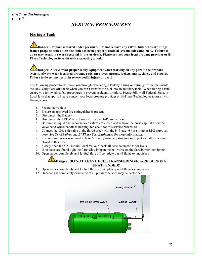
Bi-Phase Technologies LPEFI
SERVICE PROCEDURES
87
Flaring a Tank
Danger: Propane is stored under pressure. Do not remove any valves, bulkheads or fittings from a propane tank unless the tank has been properly drained (evacuated) completely. Failure to do so may result in severe personal injury or death. Please contact your local propane provider or Bi-Phase Technologies to assist with evacuating a tank.
Danger: Always wear proper safety equipment when working on any part of the propane system. Always wear insulated propane resistant gloves, aprons, jackets, pants, shoes, and goggles. Failure to do so may result in severe bodily injury or death. The following procedure will take you through evacuating a tank by flaring or burning off the fuel inside the tank. Only flare off a tank when you can’t transfer the fuel into an auxiliary tank. When flaring a tank ensure you follow all safety procedures to prevent accidents or injury. Please follow all Federal, State, or Local laws that apply. Please contact your local propane provider or Bi-Phase Technologies to assist with flaring a tank
1. Secure the vehicle 2. Ensure an approved fire extinguisher is present 3. Disconnect the Battery 4. Disconnect the LPDM wire harness from the Bi-Phase harness 5. Be sure the liquid and vapor service valves are closed and remove the brass cap – if a service
valve hand wheel handle is missing, replace it for this service procedure 6. Connect the 80% spit valve to the flare/burner with the bi-Phase -6 hose or other LPG approved
hose. See Tank Valves and Bi-Phase Test Equipment for more information. 7. Ensure flare/burner is secured at least 50’ away from any structure or object and all valves are
closed at this time 8. Slowly open the 80% Liquid Level Valve. Check all hose connections for leaks 9. If no leaks are found light the flare. Slowly open the ball valve on the flare/burner then ignite 10. Open valves completely and let fuel flare off completely until flame extinguishes
Danger: DO NOT LEAVE FUEL TRANSFERING/FLARE BURNING UNATTENDED!!!
11. Open valves completely and let fuel flare off completely until flame extinguishes 12. Once tank is completely evacuated of all pressure service may be performed

Bi-Phase Technologies LPEFI
SERVICE PROCEDURES
88
Flaring Off a Tank (Burning Off a Tank), cont’d _____________________________________________________________________________________
Warning: We recommend 50 feet clearance from the vehicle and/or buildings or combustible materials if the tank is flared.
____________________________________________________________________________________ NOTES: The kit offered from Bi-Phase Technologies is intended for vapor burning only. The flare kit is rated at 100,000 BTU’s. Other flares/burners may be used to evacuate tanks. Information for Liquid flares/burners with various BTU ratings is available. Please contact your Local propane provider or Bi-Phase Technologies for more information The time required to burn all of the fuel from the tank is based on the BTU rating of the torch – for example, 1 gallon of propane supplies 91,500 BTUs per hour; if the torch is a 1,000,000 BTU torch it would only burn approximately 10 gallons per hour; if a prefabricated flare stack is built, there would not be an orifice to restrict flow and it would burn as fast as the liquid service valve is rated to flow – for example, if the liquid service valve is flow rated at 2 GPM (gallons per minute), it could burn 120 gallon per hour When flaring a tank observe the tank for a frost or ice line. This condition usually forms when flaring/burning liquid propane. As liquid/vapor is burned from the tank and pressure is lowered, the liquid propane boils and turns into vapor. During this vaporization process the liquid propane absorbs heat energy in order to change from its liquid state to a vapor state. As this process happens frost may form near the bottom of the tank where there is cold liquid propane inside the tank. The frost is formed from water vapor in the air (humidity) and may not be observed in certain conditions. This indicates the burning process is faster than the liquid in the tank can vaporize; therefore the liquid will freeze the tank and decrease the ability of the propane liquid to vaporize. If this condition is observed spray the tank with a water hose to promote vaporization.
Warning: When flaring a tank certain conditions may cause the internal temperature of the tank to drop to the point where liquid propane may not vaporize. Close all valves on the tank and wait 5-10 minutes and then slowly open the 80% liquid level valve to ensure there is no pressure inside the tank before removing any components.
After Servicing the Tank Any time you open a tank for service you must purge the tank of any air/moisture that may have entered the tank. See Purging a Tank on P. 444. Inspect the inside of the tank for any debris and clean as necessary. Inspect all valves on the tank that may have inspection intervals. Please see the Liquefied Petroleum Gas code NFP 58 or your local propane supplier for more information. Always use new hardware, o-rings, and gaskets when re-installing components on a tank.

Bi-Phase Technologies LPEFI
PREVENTATIVE MAINTENANCE
89
Preventative Maintenance Note: Regardless of mileage, the propane fuel system should be inspected semi-annually. Inspection Form DATE VIN Year Make Model Mileage Primary Tank Serial # Secondary Tank Serial #
Pass Fail Inspect Injector rails for mis-aligned o-rings, loose mounting hardware, or cracks in the housing
Inspect engine wire harnesses that may have comin contact with injector rails/components
Inspect entire Bi-Phase wire harness for chaffing, corrosion, damage
Inspect all propane hoses in the system for chaffing, damage, corrosion, leaks. Ensure proper routing
Inspect primary hoses for proper routing and mounting. Check for wear, corrosion, leaks
Check the loop hose for proper routing and mounting. Check for wear, corrosion, leaks
Inspect all hose clamps and hardware for corrosion or loose connections
Inspect all heat shields. Any components within 18” of exhaust/heat source need to have a shield
Inspect propane tank(s) for corrosion, rust, dents, and leaks
Inspect/confirm tank identification plate is present and legible. If not legible tank must be replaced
Inspect tank mounting hardware for proper torque
Inspect tank mounting locations for any signs of stress, fatigue, cracks, corrosion
Inspect all valves on the tank(s) for corrosion, operation, and all unused valves are capped properly
Inspect transfer system is working properly. (See Transfer System for more information)
Inspect fuel fill filter and change if necessary. (See Fill Filter for more information)
Inspect fuel system pressures/amperage draws (See Testing the Fuel System for more information)
Inspect the scavenge pump (If applicable) (See The Scavenge Pump for more information)
Inspect auxiliary pump (If applicable) (See Auxiliary Pump)
Complete “Hot Soak” test on the vehicle
Test Purge Cycle for proper operation
Check Fuel gauge for proper operation
Leak test tank & entire LPEFI system with proper leak detection solution
Leaks found & repaired Yes No Where Scan PCM for any DTC’s. Any stored DTCs in computer memory? Yes No List all codes: If any DTCs found (other than the codes listed in the BPT Installation manual for the specific vehicle), repair all codes and retest Vehicle Comments: ____________________________________________________________________________________________________________

Bi-Phase Technologies LPEFI
PREVENTATIVE MAINTENANCE
90
Inspection Form (Cont’d) Connect a Scan tool and look at the vehicle Data Stream. Inspect the following parameters for proper operation:
Fuel Trims(Short/Long Term) Misfire Graphic O2 Sensor Activity Coolant Temperature operation Injector pulse width
NOTES:
ROAD TEST Road test: (Always comply with state and federal regulations when test driving the vehicle)
1. Bring truck to operating temperature >190 Degrees
2. Verify smooth idle
3. Drive truck to 65mph where limits permit
4. Verify smooth operating performance at all speeds
5. Stop and record fuel trims after test drive
Re-Check LPEFI system for leaks? Yes No Any IP Warning lights on? Yes No Repair: Yes Problem Found ____________________ ______________________________________________________________________________ Comments ____________________________________________________________________ ______________________________________________________________________________ Road test completed Yes No Comment below on any performance issues:
Technician Name: PRINT SIGNATURE DATE
Any problems found must be noted in the comment section and if a problem cannot be resolved Bi-Phase Technologies
must be contacted at 1-888-465-0571.

Bi-Phase Technologies LPEFI
PREVENTATIVE MAINTENANCE
91
Recommended Maintenance Bi-Phase recommends that the fill filter and the fuel pump filter be replaced every 30,000 miles. Each filter has a different replacement procedure that should be followed. Replace the Fill Valve, Fill Filter or Fill Hoses
Note: You will need to drain the fuel from the fill hoses and filter, but not from the fuel tank(s). There is a back-check valve where the fill hose connects to each tank, so the contents of the tank(s) cannot escape through the fill hose or fittings. It does not matter how much fuel is in the tank(s).
_____________________________________________________________________________________
Warning: The fill hose assembly may contain liquid propane. Wear insulated propane resistant gloves, shirt, pants and goggles to prevent freeze burns or injuries. _____________________________________________________________________________________
1. Park the vehicle outdoors at least 25 feet from other vehicles, buildings and sources of ignition and
secure 2. Locate the fill filter (prior to 2003, truck will be equipped with 2 filters), fill valve or fill hoses 3. Slightly loosen the flare nut on the fill filter, fill valve or fill hoses – cold liquid propane will spray
out until the hoses are empty (this should take less than a minute). Use a back-up wrench to prevent the assembly form rotating
4. Wait until the propane stops venting from the flare nut, then loosen the nut a bit further – more propane may spray out
5. Loosen flare nut(s) completely 6. Remove clamps or ties 7. Install new fill filter (directional flow), fill valve or fill hoses 8. Reinstall clamps and ties and tighten 9. Tighten flare nut(s)
Fill filter – 10-15 foot pounds Fill valve – 10-15 foot pounds (note: fill valve also has a mounting nut, tighten to 12-18
foot pounds Fill hoses – 10-15 foot pounds
10. Refuel the vehicle, check for leaks using a leak detecting probe or soapy water Bi-Phase recommends this filter be replaced every 30,000 miles (48,000 kilometers)

Bi-Phase Technologies LPEFI
PREVENTATIVE MAINTENANCE
92
Recommended Maintenance (Cont’d) Fuel Pump Filter Each LPEFI system is equipped with a fuel pump filter located on the fuel pump inside the tank. This filter is a proprietary filter and can only be purchased from Bi-Phase Technologies. If this filter is changed to an inferior filter or removed from the system, the warranty is void. Change Fuel Pump Filter
1. Secure the vehicle 2. Fuel tank must be evacuated. See Draining a Tank 3. Once tank is evacuated remove the LPDM See Removing the LPDM 4. Once LPDM is removed it is recommended to Change the Pump/Filter at the same time 5. Gently remove the fuel filter clip from the fuel filter located on the top of the filter 6. Gently remove the filter from the pump 7. Replace the fuel filter and re-install the filter clip ensuring the clip is locked
Clip Shown in Locked Position
8. Once filter is re-installed the LPDM can be re-assembled and tank purged. See Installing LPDM
and Purging a Tank for more information

Bi-Phase Technologies LPEFI
PREVENTATIVE MAINTENANCE
93
Leak Checking the System Whenever you are servicing or inspecting any components of the LPEFI system you will have to leak check all parts of the system for leaks to ensure the vehicle is safe to operate. We recommend using a combustible gas leak detector as shown below. A liquid leak detector will also work for testing the system for leaks.
General Leak Checking Procedure _____________________________________________________________________________________
Warning: Follow all safety procedures. This test must be performed outdoors and away from any ignition sources. Wear all proper safety equipment.
_____________________________________________________________________________________
1. Ensure vehicle is secured and vehicle battery is disconnected 2. Ensure you have all proper safety equipment (Goggles, Gloves, Long sleeve shirt, fire
extinguisher, pants, boots) 3. Before leak checking any components of the system ensure all fittings are properly secured and
torque marked 4. Always check one connection point at a time 5. Pressure specific fuel system area to be tested. Please see pressure test instruction areas below 6. Turn on leak detector and place input tip near joint being tested. Move input tip all around the
joint. 7. If testing with liquid solution spray the joint generously with testing solution. Observe the joint for
any signs of bubbles. If bubbles form this will indicate a leak. Let solution sit for 2-5 minutes with no bubbles before declaring the joint has no leak
8. If any leaks are found properly de-pressurize the system and repair the leak. 9. Repeat the test on all joints until no leaks are found in the system
If you have any questions in regards to leak checking any parts of the propane system please contact your local propane provider or Bi-Phase Technologies for more information.

Bi-Phase Technologies LPEFI
PREVENTATIVE MAINTENANCE
94
Fuel Fill System Leak Test
The following procedure will instruct you how to pressure test the fuel fill system for leaks. This test should be performed periodically with regular scheduled maintenance as well as whenever the fill system is serviced. The fill system connects to an 80% stop fill valve(s) on the fuel tank(s) and has an internal back check which will only allow fuel into the tank but not out.
Test Instructions _____________________________________________________________________________________
Warning: Follow all safety procedures. This test must be performed outdoors and away from any ignition sources. Wear all proper safety equipment.
_____________________________________________________________________________________ Fuel Fill System Leak Test
1. Secure the vehicle 2. Ensure all fill system components are installed and torqued correctly 3. Connect fill station/pump to fill valve on the vehicle 4. Open valve for a very brief period and pump <2gallons into the system 5. Shut of valve and disconnect pump from vehicle fill valve 6. Using an approved leak detection method check for leaks at all connection points of the fill system 7. If any leaks are found correct the leak and re-test 8. If no leaks are found leak check is complete
TYPICAL FILL SYSTEM LEAK CHECK LOCATIONS
FILL VALVE FILL FILER/TEE NOTE: If service is ever being performed on the fill system and it is found that there is no pressure in the f system when attempting to drain a hose(s); there is a leak in the system and this test must be performed to identify the leak
If you have any questions in regards to leak checking any parts of the propane system please
contact your local propane provider or Bi-Phase Technologies for more information.

Bi-Phase Technologies LPEFI
PREVENTATIVE MAINTENANCE
95
Primary Hoses/Rail/Injector Leak Test
The following procedure will instruct you how to pressure test the Primary fuel lines, fuel rails, and injector for leaks. Use extreme caution when checking for leaks and ensure all proper safety equipment is being used during testing
Test Instructions ______________________________________________________________________________
Warning: Follow all safety procedures. This test must be performed outdoors and away from any ignition sources. Wear all proper safety equipment.
_____________________________________________________________________________________ Primary Hoses/Rail/Injector Leak Test
1. Secure the vehicle 2. Disconnect the battery 3. Ensure all system components are installed and torqued correctly 4. Remove LPDM harness from the main Bi-Phase Harness 5. Connect the “3 Switch Box” to the LPDM harness (See LPEFI Testing Equipment for more
information) 6. Connect the Bi-Phase Pressure Gauge Set to the LPDM (See LPEFI Testing Equipment for more
information) 7. Purge the primary fuel lines using the “3 switch box”(See Purging Primary Fuel Lines) 8. Once fuel lines are purged turn on the supply valve on the “3 switch box” 9. Next turn on the pump using the “3 switch box” 10. Starting at the LPDM check ALL hose connection points for leaks using an approved leak
detector (See Leak Checking the System) 11. If any leaks are found turn off the 3 switch box, de-pressurize/drain the fuel system and repair the
leak (See Draining the Fuel Lines) Repeat leak test 12. Once all hose connections have been leak checked check all injector connection points for leaks 13. Repair any leaks that are found (See Servicing the Injector for more information) 14. Once all hoses/injectors are leak tested and no leaks are present you may disconnect all test
equipment 15. Leak Test is now complete
TYPICAL PRIMARY HOSE/RAIL/INJECTOR LEAK CHECK LOCATIONS
Loop/Primary Hose QD Injector/Intake/Rail
If you have any questions in regards to leak checking any parts of the propane system please contact your local propane provider or Bi-Phase Technologies for more information.

Bi-Phase Technologies LPEFI
PREVENTATIVE MAINTENANCE
96
Fuel Transfer System Leak Test (Dual Tank Trucks) The following procedure will instruct you how to pressure test the Transfer System fuel lines and any associated fittings. Use extreme caution when checking for leaks and ensure all proper safety equipment is being used during testing
Test Instructions _____________________________________________________________________________________
Warning: Follow all safety procedures. This test must be performed outdoors and away from any ignition sources. Wear all proper safety equipment.
_____________________________________________________________________________________ Transfer System Leak Test
1. Secure the vehicle 2. Disconnect the battery 3. Ensure all system components are installed and torqued correctly 4. Remove Secondary LPDM harness from the main Bi-Phase Harness 5. Connect the “3 Switch Box” to the Secondary LPDM harness (See LPEFI Testing Equipment for
more information) 6. Purge the transfer line to ensure line is pressurized (See The Transfer System for more
information) 7. Once transfer line is purged turn on the pump switch on the “3 switch box” 8. Using an approved leak detector check all connection points in the transfer system for any leaks 9. If any leaks are found de-pressurize/drain the transfer system and repair leak. (See Draining the
Fuel Lines for more information) 10. Once all fuel lines are leak tested and no leaks are found the system test is complete 11. Disconnect all test equipment
TYPICAL TRANSFER SYSTEM TEST LOCATION
TRANSFER HOSE INTO 80% STOP FILL VALVE
NOTE: If service is ever being performed on the Transfer System and it is found that there is no pressure in the system when attempting to drain the hose(s), there is a leak in the system and this test must be performed to identify the leak. If there is a leak in the transfer system it may cause problems when trying to transfer fuel from the Secondary Tank into the Primary Tank
If you have any questions in regards to leak checking any parts of the propane system please
contact your local propane provider or Bi-Phase Technologies for more information.
Fuel Tank Leak Test

Bi-Phase Technologies LPEFI
PREVENTATIVE MAINTENANCE
97
The following procedure will instruct you how to pressure test the tank and all of the components on the tank. This includes LPDM, Liquid Service Valve, 80% Stop Fill Valve, 80% Liquid Level Valve, PRV, and Fuel Gauge Float Assembly. (See Tank Valves for more information). The following procedure takes you through testing the tank using a small amount of propane pressure. Test Instructions _____________________________________________________________________________________
Warning: Follow all safety procedures. This test must be performed outdoors and away from any ignition sources. Wear all proper safety equipment.
_____________________________________________________________________________________ Tank Leak Test (Propane Pressure) The following procedure will tank you through pressure testing for leaks using a small amount of propane pressure. The vehicle should be set up to evacuate a tank of all propane pressure if any propane leaks are found. (See Evacuating a Tank for more information)
1. Secure the vehicle 2. Disconnect the battery 3. Ensure all system components are installed and torqued correctly 4. Ensure all valves are closed 5. Purge the tank of any air that may be present inside the tank (See Purging a Tank) 6. Once tank is purged connect the Bi-Phase pressure gauge set to the LPDM (See LPEFI Test
Tools) 7. Fill tank being tested with a small amount of propane (< 2 gal) 8. Do an initial test of all valves, bulkheads, and components attached to the fuel tank to ensure there
are no leaks with an approved leak detector 9. If any leaks are found stop, evacuate the tank, and repair leak. If no leaks are found continue onto
step 10 10. Observe pressure gauge. Allow pressure to stabilize. 11. Observe Propane Supply Pressure Chart. Pressure should correlate with observed air/tank
temperature
Tank Leak Test (Propane Pressure) (Cont’d)

Bi-Phase Technologies LPEFI
PREVENTATIVE MAINTENANCE
98
12. Check all valves, plugs, bulkheads, and any other items that insert into the tank for leaks using an
approved leak detection device 13. Repair any leaks by evacuating the tank and performing necessary repair (See Evacuating a Tank;
Valve Replacement for more information) 14. If no leaks are found remove all test equipment 15. Test is now complete
TYPICAL TANK TEST LOCATIONS
80% STOP FILL/LIQUID SERVICE VALVE YLPDM
80% Stop Fill Valve Testing

Bi-Phase Technologies LPEFI
PREVENTATIVE MAINTENANCE
99
The 80% stop fill valves should be checked regularly with the LPEFI system for correct operation to prevent overfilling of a tank. Overfilling of a propane tank is dangerous and could lead to damage, injury, or death. The following procedure will instruct you how to inspect an 80% stop fill valve for proper function. Ensure this test is performed outdoors at least 25ft from any structure. Test Instructions _____________________________________________________________________________________
Warning: Follow all safety procedures. This test must be performed outdoors and away from any ignition sources. Wear all proper safety equipment.
_____________________________________________________________________________________ Testing 80% stop fill valve
1. Secure Vehicle on level ground 2. Ensure Tank has been purged and leak checked (See Purging a Tank; Leak Checking for more
information) 3. Ensure Fill System has been Leak Checked (See Leak Checking for more information) 4. Hook up fill station hose to fill valve and prepare to fill the vehicle (See Filling the Vehicle) 5. Locate the 80% fixed level valve (spitter) Slowly open the valve until propane vapor starts to
escape 6. Start to fill the vehicle 7. Observe the spitter valve as the tank fills 8. The 80% stop fill valve should shut off fuel flow into the tank as soon as white mist/propane vapor
starts to vent from the 80% fixed level gauge 9. If tank continues to fill after liquid (white mist) is coming out of the 80% stop fill valve the 80%
stop fill valve should be inspected for proper function. (See Evacuating a Tank; Servicing the Valves for more information)
10. Turn off pump and close all valves 11. If tank shuts off as described in step 8 the 80% stop fill valve is operating correctly 12. Proceed to Testing 80% stop Fill Valve (Back Check)
Testing 80% stop fill valve (Back Check) The following procedure will instruct you the proper procedure to test an 80% stop fill valve back check valve for proper operation. The back check valve is a built in mechanism that prevents fuel from exiting the tank through the 80% stop fill valve.
1. Ensure there is fuel in the tank 2. Drain the fill hose or transfer hose that connects to the 80% stop fill valve (See Draining
the Fill Hose; Draining the Transfer Hose for more information) 3. Remove the hose from the 80% stop fill valve 4. Using an approved leak detector check the valve for any leaks. If any leaks are found
evacuate the tank and replace the valve (See Evacuating a Tank; Servicing the Valves for more information)
5. If no leaks are found re-install all hoses and leak check. (See Leak Checking) 6. Test is now complete

Bi-Phase Technologies LPEFI
TANK VALVES
100
Tank Valves Most fuel tanks in the Bi-Phase system have 5 different types of valves configured in various locations on the tank. Tank valves should be inspected regularly for damage, corrosion, leaks, and improper operation.
Propane is stored under pressure and service to any portion of the tank or valves should not be performed until the tank has been drained/evacuated with all pressure removed. (See
Evacuating a Tank for more information) __________________________________________________________________________________
80% Stop Fill Valve
The 80% stop Fill Valve is a valve that only allows a propane tank to be filled to the 80% capacity. The valve is installed at the 80% level on the tank and has a float assembly that automatically shuts off incoming fuel flow when fueling a tank once the float arm shuts the valve. Some tanks have a special 80% Stop Fill Valve that mounts in the lower portion of the tank and has a custom float arm that will still shut off the valve once liquid level reaches 80% capacity. This Valve installs into a ¾” NPT female pipe fitting welded onto the tank by the manufacturer. The valve MUST be clocked properly for the valve to function properly. On the front face of the valve the manufacturer stamps in the word “TOP”. This portion of the valve must be facing upward to ensure proper function If the valve is not installed correctly the valve may not allow fuel into the tank. Whenever installing fittings onto into the 80% Stop Fill Valve you must use a back up wrench to ensure the 80% Stop Fill Valve does not rotate when tightening other fittings. 80% Stop Fill Valves should be tested inspected regularly for proper operation.

Bi-Phase Technologies LPEFI
TANK VALVES
101
Tank Valves (Cont’d) 80% Liquid Level Valve
The 80% Liquid Level Valve is equipped on every propane tank. The valve has a .054” orifice that is closed and opened manually with a valve. The valve is inserted into a welded fitting on the tank at the 80% liquid level. This valve is commonly referred to as the “Spit” or “Spitter” valve. During filling of a tank this valve can be opened to indicate when a propane tank has reached 80% capacity. (All propane tanks are to only be filled to 80% liquid level). To ensure proper function all you should always place the tank or vehicle on flat level ground to ensure valve is at the 80% liquid level. This valve can also be used to flare/burn off a tank using propane vapor (See Flaring a Tank) The valve is inserted into a ¼” female NPT thread and has a ¼” male SAE 45° flare fitting to attach service hoses to if needed. Always check for proper operation during regular service of the vehicle Fill Valve
O-Ring: Sherwood P/N G216B
The Fill Valve is a valve that mounts onto the fuel tank in which you attach the filling station nozzle to allow you to fill the fuel tanks with propane. The fitting is a 1 ¾” ACME style fitting commonly used on larger propane tanks such as your home heading propane tank, RV propane tanks, and fork lift propane tanks. The valve is equipped with a one way back-check that only allows fuel into the fitting. The fitting is equipped with a ½” ASME 45° flare fitting in which the fill hoses attach to. The valve has a serviceable O-ring that requires regular inspection to ensure proper function.
- O-Ring Seal : Sherwood P/N G216B

Bi-Phase Technologies LPEFI
TANK VALVES
102
Tank Valves (Cont’d) Fuel Gauge Float Assembly
Float Assembly gasket
The Fuel Gauge Float Assembly is the internal mechanism that will correlate to the fuel card the level of liquid propane inside the tank. Each diameter tank has a different float assembly. The float is also different depending on where it is mounted in the tank. Float assemblies are usually mounted in the upper 45 or lower 45 of a propane tank depending on application. The float is held into the tank with 4 screws and seals with a gasket. The gasket is a serviceable part and may be ordered from Bi-Phase Technologies or tank manufacturer. When servicing the float assembly the float must be installed correctly to ensure proper function. Contact Bi-Phase technologies for more information about specific float assemblies Liquid Service Valve
Liquid Service Valve
The Liquid Service valve is equipped on every propane tank. This valve is a manually operated hand wheel type valve that is also equipped with an overflow protection device. The overflow protection device will trip when flow reaches > 3 gallons/min. The valve is installed into the tank and will access the liquid portion of the fuel inside the tank. The valve assists in transferring fuel from one tank to another, flaring a tank, or purging a tank. The valve installs into a ¾ NPT female thread and has a 3/8” SAE 45° flare outlet to attach service hoses to. This valve should have a brass cap installed on the outlet whenever not in use.

Bi-Phase Technologies LPEFI
TANK VALVES
103
Tank Valves (Cont’d) PRV (Pressure Relief Valve)
Pressure Relief Valve
The PRV (Pressure Relief Valve) is equipped on every propane fuel tank. This valve is a hydrostatic valve that opens in the event internal tank pressure reaches > 312PSI. All propane tanks have a PRV. In the event the pressure inside the fuel tank reaches >312PSI it will open and vent propane until the tank pressure reaches <312 PSI. The PRV is installed into the tank in the vapor space, and if installed on the bottom 45 of the tank it will have in internally welded pipe up to the vapor space. The valve may be mounted in various locations on the tank and the discharge direction must comply with NFPA 58 standards. NFP 58 (2011 edition) (Current as of Jan 2014) 11.8.5 Pressure Relief Valve Discharge Systems (Engine Fuel Systems) 11.8.5.1 The Pressure relief valve discharge from fuel containers on vehicles other than industrial (and forklift) trucks shall be in accordance with the following:
1. It shall be directed upward or downward within 45 degrees of vertical. 2. It shall not directly impinge on the vehicle fuel container(s), the exhaust system,
or any other part of the vehicle 3. It shall not be directed into the interior of the vehicle
Please reference NFPA 58 11.8.5.2 when piping away the PRV discharge system. Contact your local propane provider or Bi-Phase Technologies for more information.

Bi-Phase Technologies LPEFI
SPECIFICAITIONS
104
Spark Plugs
8.1 L GMC Manufacture Type Gap AC Delco R42 – LTS 0.35 NGK TR6 0.35
1.0 L GMC & Isuzu Manufacture Type Gap NGK IFR7F-8DS (#5794) 0.31
Sending Unit Resistance Values
GMC C series Year Gauges (Empty to Full) Tanks 1999–2002 0 to 90 gauge(s) single or dual tank(s) 2003–2004 40 to 240 gauge single tank (no additional dash gauge) 2003–2005 0 to 90 gauges dual tanks (additional dash gauge) 2005 40 to 240 gauge(s) dual tanks (no additional dash gauge) 2006-2009 240 to 40 gauge primary tank 2006-2009 40 to 240 gauge secondary tank
Isuzu Year Gauges (Empty to Full) Tanks 2009-2012 40 to 240 gauge single 2012-2013 240-to 40 gauge dual
G van Year Gauges (Empty to Full) Tanks 2009-2010 240 to 40 gauge single 2013-2014 240 to 40 gauge dual
E450 Year Gauges (Empty to Full) Tanks 2010 180-10 gauge single 2010-2011 180-10 gauge dual (dash gauge read only) 2010-2011 0-90 gauge dual

Bi-Phase Technologies LPEFI
SPECIFICAITIONS
105
Calibration Codes
Year MAKE/MODEL FUEL SYSTEM CODE 2000 GMC 8.1L 37400090 2001-2002 GMC 8.1L 37010201 2004 GMC 8.1L 12616870 2005 GMC 8.1L 12608398 2005 GMC 8.1L (Dual Tank) 12584551 2006 GMC 8.1L 12608399 2007 GMC 8.1L 12608399 2008 GMC 8.1L 12587835 2009 ISUZU 6.0L 12616339 2012 ISUZU 6.0L 12648804 2013 ISUZU 6.0L 12658825 2014 ISUZU 6.0L 12661047 2009 GMC 6.0L 12651364 2010 GMC 6.0L 12645426 2012 GMC 6.0L XXXXXX 2013 GMC 6.0L 12655243 2014 GMC 6.0L 12659596

Bi-Phase Technologies LPEFI
SPECIFICAITIONS
106
LPCM (LIQUID PROPANE CONTROL MODULE) The LPCM (tank control box) is located near the primary LPDM. In most cases, it is located on a tank guard at the back of the primary (main) fuel tank. On early models, 1999-2002, the (red) box was totally integrated into one box that controls all of the internal supply/return valve and pump functions, as well as the strategies of the purge cycle. The Black, Green, and Blue LPCM’s have taken the fuel pump power supply out of the box and routed it through a relay. The tank control box operating strategy did not change; only the fuel pump relay was added. Previous service manuals explained an internal diagnostic code retrieval ability that the new box does not have. This change was effective starting in the 2003 GM products only. All mounting hardware and locations are the same between this style box. Please see the Specifications section of this manual for vehicle wiring diagrams. After 2009 any purge box that requires replacing will receive a green box with auto purge. Please contact Bi-Phase technologies for more information Black, Blue or Green Control Box Functions
TANK INPUTS 1. Ground 2. +12 Battery (Always Hot) through 15A fuse 3. Looks for +12V when engine is running 4. Door Signal + 5. (Optional) flashing indicator lamp 6. Door Signal – TANK OUTPUTS 1. Will provide 12V when active 2. Will provide 12V when active 3. Will provide 12V when active 4. Ground

Bi-Phase Technologies LPEFI
SPECIFICAITIONS
107
LPCM (Cont’d)
Red Control Box Functions
NOTE: New boxes are black, blue or green in color
Connect original harness to these two connectors

Bi-Phase Technologies LPEFI
SPECIFICAITIONS
108
LPCM, (Cont’d) CINCH LPCM (2012)
Connector Mating Torque: 15-20 in/lbs Connector Socket Size: SAE ¼” Mounting Bolts: M6x1.0x35mm Mounting Nuts: M6x1.0
GM SAVANNA/EXPRESS (2012-2014) COMMON APPLICAION (INSIDE FRAME RAIL, FRONT OF PRIMARY TANK) (BOLTED ONTO END OF FUEL TANK)

Bi-Phase Technologies LPEFI
SPECIFICAITIONS
109
CINCH LPCM (2013) (Cont’d) Pin Index
Pin ID
PIN ASSIGNMENT TYPICAL USE VOLTAGES COLOR
ON OFF PRIM/TRAC 1A N/A 1B N/A 1C N/A 1D N/A 1E PUMP 1 RELAY DRIVER PRIMARY PUMP RELAY DRIVER 0V 12V RED/BLK 1F SUPPLY SOLONOID DRIVER SUPPLY VALVE DRIVER 12V 0V ORN 1G PUMP 2 RELAY DRIVER SECONDARY TANK RELAY DRIVER 0V 12V BLU 1H LPCM 12V. LPCM 12V. POWER 12V 0V RED 1J N/A 0V 12V 1K RETURN SOLONOID DRIVER RETURN VALVE DRIVER 12V 0V YEL 2A N/A 2B N/A 2C FUEL LEVEL OUTPUT FUEL LEVEL OUTPUT TO VEHICLE PCM PUR 2D FUEL SENSOR 1 INPUT PRIMARY TANK FUEL LEVEL GRN 2E FUEL SENSOR 2 INPUT SECONDARY TANK FUEL LEVEL BRN 2F N/A 2G N/A 2H N/A 2J KEY/PUMP INPUT FUEL PUMP SIGNAL FROM VEHICLE 12V 0V WHT/GRY 2K CHASSIS GROUND LPCM GROUND
BLK
3A KILL ELAY DRIVER IDLE SHUTDOWN RELAY DRIVER 0V 12V BLU/PNK 3B SPARE RELAY DRIVER 3C SUPPLY RELAY DRIVER SUPPLY VALVE/SCAVENGE PUMP RELAY DRIVER 0V 12V ORN/WHT 3D PARK SIGNAL PARK SIGNAL FROM VEHICLE PCM YEL/PUR 3E NEUTRAL SIGNAL NEUTRAL SIGNAL FROM VEHICLE PCM YEL/GRN 3F DOOR SIGNAL DRIVER'S DOOR SIGNAL FROM PCM WHT 3G N/A 3H WAIT TO START LIGHT WAIT TO START 12V. 12V 0V GRY 3J N/A 3K N/A

Bi-Phase Technologies LPEFI
SPECIFICAITIONS
110
GM Medium Duty 1999/2000/2001/2002

Bi-Phase Technologies LPEFI
SPECIFICAITIONS
111

Bi-Phase Technologies LPEFI
SPECIFICAITIONS
112

Bi-Phase Technologies LPEFI
SPECIFICAITIONS
113

Bi-Phase Technologies LPEFI
SPECIFICAITIONS
114
Tank control box retrofit adapting wiring diagram and harness configuration. 1999-2002 vehicles with red tank control box will be replaced with a black control box, relay and this adaptor harness. Some early 2003 models will have this harness adaptor too.

Bi-Phase Technologies LPEFI
SPECIFICAITIONS
115

Bi-Phase Technologies LPEFI
SPECIFICAITIONS
116

Bi-Phase Technologies LPEFI
SPECIFICAITIONS
117

Bi-Phase Technologies LPEFI
SPECIFICAITIONS
118

Bi-Phase Technologies LPEFI
SPECIFICAITIONS
119

Bi-Phase Technologies LPEFI
SPECIFICAITIONS
120

Bi-Phase Technologies LPEFI
SPECIFICAITIONS
121

Bi-Phase Technologies LPEFI
SPECIFICAITIONS
122

Bi-Phase Technologies LPEFI
SPECIFICAITIONS
123

Bi-Phase Technologies LPEFI
SPECIFICAITIONS
124
LPEFI Secondary Harness Electrial Wiring Diagram With ISD 2011 Ford Auxilary Pump 5.4L

Bi-Phase Technologies LPEFI
SPECIFICAITIONS
125
LPEFI Main Harness Electrial Wiring Diagram With ISD 2013 GMC W4500 Dual Tanks 6.0L

Bi-Phase Technologies LPEFI
SPECIFICAITIONS
126
LPEFI Main Harness Electrial Wiring Diagram With ISD 2013 Isuzu NPR Dual Tanks 6.0L

Bi-Phase Technologies LPEFI
SPECIFICAITIONS
127
Tank & Hose Configurations

Bi-Phase Technologies LPEFI
SPECIFICAITIONS
128

Bi-Phase Technologies LPEFI
SPECIFICAITIONS
129
Tank & Hose Configuration

Bi-Phase Technologies LPEFI
SPECIFICAITIONS
130

Bi-Phase Technologies LPEFI
SPECIFICAITIONS
131

Bi-Phase Technologies LPEFI
SPECIFICAITIONS
132

Bi-Phase Technologies LPEFI
SPECIFICAITIONS
133

Bi-Phase Technologies LPEFI
SPECIFICAITIONS
134

Bi-Phase Technologies LPEFI
SPECIFICAITIONS
135

Bi-Phase Technologies LPEFI
SPECIFICAITIONS
136
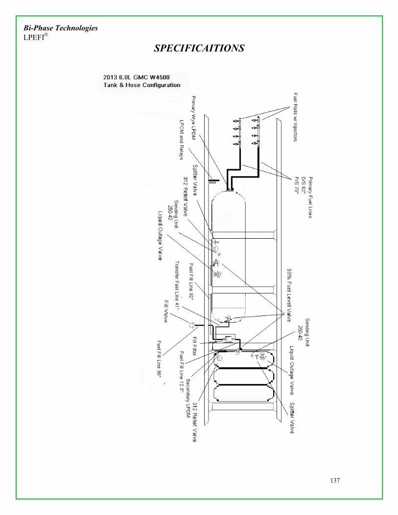
Bi-Phase Technologies LPEFI
SPECIFICAITIONS
137

Bi-Phase Technologies LPEFI
SPECIFICAITIONS
138

Bi-Phase Technologies LPEFI
CONTACT INFORMATION
139
Bi-Phase Technologies, LLC 2945 Lone Oak Drive, Suite 150
Eagan, MN 55121
Office: 952-886-6450 Office Fax: 651-681-4441
Technical Questions/Parts: – 888-465-0571