lpwa data logger - amit wireless… · lpwa data logger 3 . chapter 1 introduction 1.1 introduction...
TRANSCRIPT
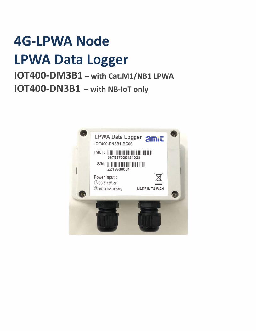
4G-LPWA Node LPWA Data Logger IOT400-DM3B1 – with Cat.M1/NB1 LPWA IOT400-DN3B1 – with NB-IoT only
LPWA Data Logger
2
Chapter 1 Introduction ...................................................................................................................................3 1.1 Introduction ..................................................................................................................................... 3
1.2 Contents List ................................................................................................................................... 4
1.2.1 Package Contents ................................................................................................................... 4
1.2.2 Optional Accessories .............................................................................................................. 4
1.3 Hardware Configuration .................................................................................................................. 5
1.4 LED Indication ................................................................................................................................ 6
1.5 Installation & Maintenance Notice ................................................................................................... 7
1.5.1 SYSTEM REQUIREMENTS ................................................................................................ 7
1.5.2 WARNING ........................................................................................................................... 7
1.5.4 Product Information for CE RED Requirements ..................................................................... 9
1.6 Hardware Installation ......................................................................................................................11
1.6.1 Open the Top Cover..............................................................................................................11
1.6.2 Insert SIM Card................................................................................................................... 13
1.6.3 Install Battery...................................................................................................................... 14
1.6.4 Connecting to External Devices ........................................................................................... 16
1.6.5 Connecting Console Port for PC Configuration Tool ............................................................. 23
1.6.6 Power On the IOT400.......................................................................................................... 25
1.6.7 Setup with Windows-based Configuration Tool .................................................................... 27
1.6.8 Device Mount and Screw Back the Top Cover ...................................................................... 29
Chapter 2 Device Configuration ................................................................................................................... 30 2.1 Device Status................................................................................................................................. 30
2.2 LPWA Configuration ..................................................................................................................... 31
2.3 I/O Configuration .......................................................................................................................... 32
2.4 Modbus Configuration ................................................................................................................... 34
2.5 Schedule Configuration.................................................................................................................. 36
2.6 Server Configuration ..................................................................................................................... 38
2.7 System Configuration .................................................................................................................... 40
Chapter 3 Data Logs .................................................................................................................................... 42 3.1 Data Log Format ........................................................................................................................... 42
LPWA Data Logger
3
Chapter 1 Introduction 1.1 Introduction Congratulations on your purchase of this outstanding product: LPWA Data Logger. For IIoT applications, AMIT LPWA Data Logger is absolutely the right choice. With built-in world-class 4G LPWA module*1, you just need to insert SIM card from local mobile carrier to get to remote server in the internet. The IOT400 is a cost-effective low complexity solution for simple data acquisition and wireless telemetry. 4G LPWA, either Cat.M1 or NB1, is optimized for low bandwidth IoT traffic and leverages existing 4G infrastructure to transmit data at low data rates. It allows massive deployment of wireless IoT with carrier-level security. Thanks to the power saving technology, the IOT400 has ultra-low power consumption which allows it to operate on a single battery for years*2. Main Features:
• Simple device with various interfaces (AI / DI / RS485) for IIoT field data acquisition. • Storage of the meter/sensor readings in non-volatile memory of the data logger. • Transfer of logged data to designated remote server by schedule rule, or on an event at the site. • Internal battery-powered design for easy deployment; Low power consumption and work without
changing the battery for years. • Automatic issuing low battery power alerts to remote server for device or battery replacement. • Configuring the data logger via a PC with a convenient configuration utility. • Water-resist, dust-resist IP65 enclosure for installing in severe environment.
Before you install and use this product, please read this manual in detail for fully exploiting the functions of this product.
1 IOT400-DMxxx for Cat.M1/NB1(NB-IoT), IOT400-DNxxx for NB-IoT. 2 The battery life time depends on actual usage (frequency of data logging, and data uploading) of the data logger.
LPWA Data Logger
4
1.2 Contents List
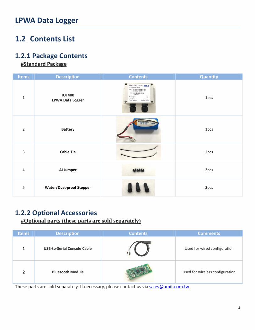
1.2.1 Package Contents #Standard Package
Items Description Contents Quantity
1 IOT400 LPWA Data Logger
1pcs
2 Battery
1pcs
3 Cable Tie
2pcs
4 AI Jumper
3pcs
5 Water/Dust-proof Stopper
3pcs
1.2.2 Optional Accessories #Optional parts (these parts are sold separately)
Items Description Contents Comments
1 USB-to-Serial Console Cable
Used for wired configuration
2 Bluetooth Module
Used for wireless configuration
These parts are sold separately. If necessary, please contact us via [email protected]
LPWA Data Logger
5
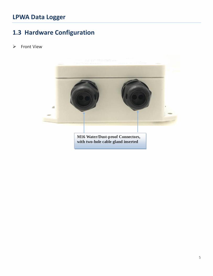
1.3 Hardware Configuration
Front View
M16 Water/Dust-proof Connectors, with two-hole cable gland inserted
LPWA Data Logger
6
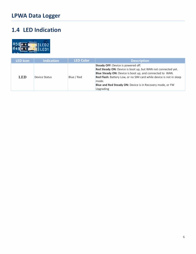
1.4 LED Indication
LED Icon Indication LED Color Description
LED Device Status Blue / Red
Steady OFF: Device is powered off. Red Steady ON: Device is boot up, but WAN not connected yet. Blue Steady ON: Device is boot up, and connected to WAN. Red Flash: Battery Low, or no SIM card while device is not in sleep mode. Blue and Red Steady ON: Device is in Recovery mode, or FW Upgrading
LPWA Data Logger
7
1.5 Installation & Maintenance Notice
1.5.1 SYSTEM REQUIREMENTS Network Requirements • ISP provided SIM card for 4G LPWA service
Configuration Tool Requirements
Computer with the following: • Windows®7 or Windows 10 • An installed Ethernet adapter • A USB 2.0, or later for serial console, or • Bluetooth 4.x, or later for wireless console
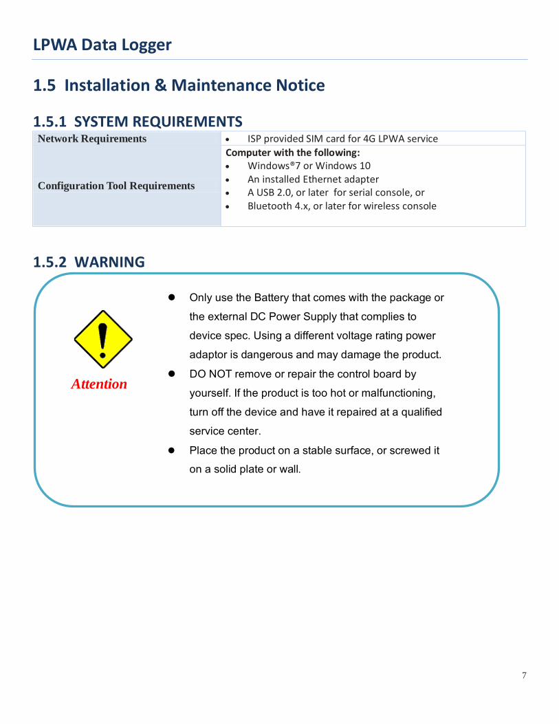
1.5.2 WARNING
Only use the Battery that comes with the package or the external DC Power Supply that complies to device spec. Using a different voltage rating power adaptor is dangerous and may damage the product.
DO NOT remove or repair the control board by yourself. If the product is too hot or malfunctioning, turn off the device and have it repaired at a qualified service center.
Place the product on a stable surface, or screwed it on a solid plate or wall.
Attention
LPWA Data Logger
8
Federal Communication Commission Interference Statement This device complies with Part 15 of the FCC Rules. Operation is subject to the following two conditions: (1) This device may not cause harmful interference, and (2) this device must accept any interference received, including interference that may cause undesired operation. This equipment has been tested and found to comply with the limits for a Class B digital device, pursuant to Part 15 of the FCC Rules. These limits are designed to provide reasonable protection against harmful interference in a residential installation. This equipment generates, uses and can radiate radio frequency energy and, if not installed and used in accordance with the instructions, may cause harmful interference to radio communications. However, there is no guarantee that interference will not occur in a particular installation. If this equipment does cause harmful interference to radio or television reception, which can be determined by turning the equipment off and on, the user is encouraged to try to correct the interference by one of the following measures: - Reorient or relocate the receiving antenna. - Increase the separation between the equipment and receiver. - Connect the equipment into an outlet on a circuit different from that to which the receiver is connected. - Consult the dealer or an experienced radio/TV technician for help. FCC Caution: Any changes or modifications not expressly approved by the party responsible for compliance could void the user's authority to operate this equipment. This transmitter must not be co-located or operating in conjunction with any other antenna or transmitter.
FOR PORTABLE DEVICE USAGE (<20m from body/SAR needed) Radiation Exposure Statement: The product comply with the FCC portable RF exposure limit set forth for an uncontrolled environment and are safe for intended operation as described in this manual. The further RF exposure reduction can be achieved if the product can be kept as far as possible from the user body or set the device to lower output power if such function is available. FOR MOBILE DEVICE USAGE (>20cm/low power) Radiation Exposure Statement: This equipment complies with FCC radiation exposure limits set forth for an uncontrolled environment. This equipment should be installed and operated with minimum distance 20cm between the radiator & your body. FOR COUNTRY CODE SELECTION USAGE (WLAN DEVICES) Note: The country code selection is for non-US model only and is not available to all US model. Per FCC regulation, all WiFi product marketed in US must fixed to US operation channels only.
LPWA Data Logger
9
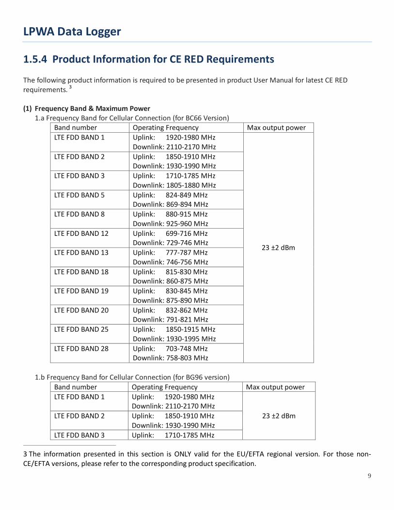
1.5.4 Product Information for CE RED Requirements The following product information is required to be presented in product User Manual for latest CE RED requirements. 3 (1) Frequency Band & Maximum Power
1.a Frequency Band for Cellular Connection (for BC66 Version) Band number Operating Frequency Max output power LTE FDD BAND 1 Uplink: 1920-1980 MHz
Downlink: 2110-2170 MHz
23 ±2 dBm
LTE FDD BAND 2 Uplink: 1850-1910 MHz Downlink: 1930-1990 MHz
LTE FDD BAND 3 Uplink: 1710-1785 MHz Downlink: 1805-1880 MHz
LTE FDD BAND 5 Uplink: 824-849 MHz Downlink: 869-894 MHz
LTE FDD BAND 8 Uplink: 880-915 MHz Downlink: 925-960 MHz
LTE FDD BAND 12 Uplink: 699-716 MHz Downlink: 729-746 MHz
LTE FDD BAND 13 Uplink: 777-787 MHz Downlink: 746-756 MHz
LTE FDD BAND 18 Uplink: 815-830 MHz Downlink: 860-875 MHz
LTE FDD BAND 19 Uplink: 830-845 MHz Downlink: 875-890 MHz
LTE FDD BAND 20 Uplink: 832-862 MHz Downlink: 791-821 MHz
LTE FDD BAND 25 Uplink: 1850-1915 MHz Downlink: 1930-1995 MHz
LTE FDD BAND 28 Uplink: 703-748 MHz Downlink: 758-803 MHz
1.b Frequency Band for Cellular Connection (for BG96 version)
Band number Operating Frequency Max output power LTE FDD BAND 1 Uplink: 1920-1980 MHz
Downlink: 2110-2170 MHz 23 ±2 dBm LTE FDD BAND 2 Uplink: 1850-1910 MHz
Downlink: 1930-1990 MHz LTE FDD BAND 3 Uplink: 1710-1785 MHz
3 The information presented in this section is ONLY valid for the EU/EFTA regional version. For those non-CE/EFTA versions, please refer to the corresponding product specification.
LPWA Data Logger
10
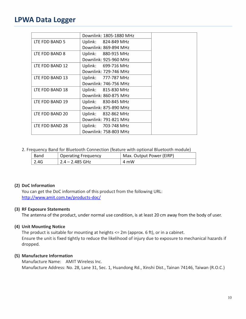
Downlink: 1805-1880 MHz LTE FDD BAND 5 Uplink: 824-849 MHz
Downlink: 869-894 MHz LTE FDD BAND 8 Uplink: 880-915 MHz
Downlink: 925-960 MHz LTE FDD BAND 12 Uplink: 699-716 MHz
Downlink: 729-746 MHz LTE FDD BAND 13 Uplink: 777-787 MHz
Downlink: 746-756 MHz LTE FDD BAND 18 Uplink: 815-830 MHz
Downlink: 860-875 MHz LTE FDD BAND 19 Uplink: 830-845 MHz
Downlink: 875-890 MHz LTE FDD BAND 20 Uplink: 832-862 MHz
Downlink: 791-821 MHz LTE FDD BAND 28 Uplink: 703-748 MHz
Downlink: 758-803 MHz 2. Frequency Band for Bluetooth Connection (feature with optional Bluetooth module)
Band Operating Frequency Max. Output Power (EIRP) 2.4G 2.4 – 2.485 GHz 4 mW
(2) DoC Information
You can get the DoC information of this product from the following URL: http://www.amit.com.tw/products-doc/
(3) RF Exposure Statements
The antenna of the product, under normal use condition, is at least 20 cm away from the body of user. (4) Unit Mounting Notice
The product is suitable for mounting at heights <= 2m (approx. 6 ft), or in a cabinet. Ensure the unit is fixed tightly to reduce the likelihood of injury due to exposure to mechanical hazards if dropped.
(5) Manufacture Information
Manufacture Name: AMIT Wireless Inc. Manufacture Address: No. 28, Lane 31, Sec. 1, Huandong Rd., Xinshi Dist., Tainan 74146, Taiwan (R.O.C.)
LPWA Data Logger
11
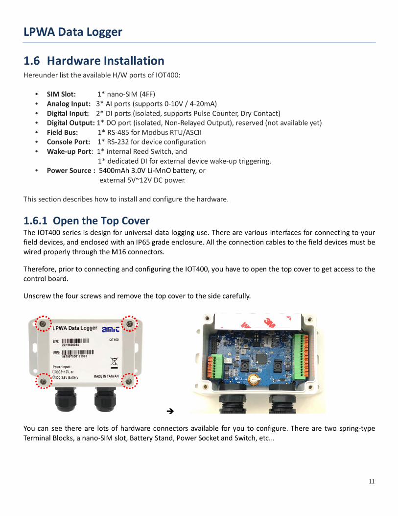
1.6 Hardware Installation Hereunder list the available H/W ports of IOT400:
• SIM Slot: 1* nano-SIM (4FF) • Analog Input: 3* AI ports (supports 0-10V / 4-20mA) • Digital Input: 2* DI ports (isolated, supports Pulse Counter, Dry Contact) • Digital Output: 1* DO port (isolated, Non-Relayed Output), reserved (not available yet) • Field Bus: 1* RS-485 for Modbus RTU/ASCII • Console Port: 1* RS-232 for device configuration • Wake-up Port: 1* internal Reed Switch, and
1* dedicated DI for external device wake-up triggering. • Power Source : 5400mAh 3.0V Li-MnO battery, or
external 5V~12V DC power. This section describes how to install and configure the hardware.
1.6.1 Open the Top Cover The IOT400 series is design for universal data logging use. There are various interfaces for connecting to your field devices, and enclosed with an IP65 grade enclosure. All the connection cables to the field devices must be wired properly through the M16 connectors.
Therefore, prior to connecting and configuring the IOT400, you have to open the top cover to get access to the control board.
Unscrew the four screws and remove the top cover to the side carefully.
You can see there are lots of hardware connectors available for you to configure. There are two spring-type Terminal Blocks, a nano-SIM slot, Battery Stand, Power Socket and Switch, etc...
LPWA Data Logger
12
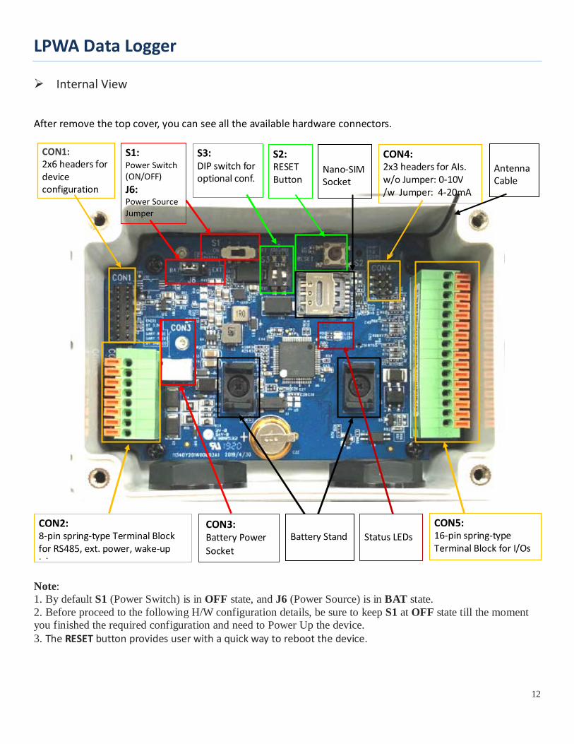
Internal View
After remove the top cover, you can see all the available hardware connectors.
Note: 1. By default S1 (Power Switch) is in OFF state, and J6 (Power Source) is in BAT state. 2. Before proceed to the following H/W configuration details, be sure to keep S1 at OFF state till the moment you finished the required configuration and need to Power Up the device. 3. The RESET button provides user with a quick way to reboot the device.
S1: Power Switch (ON/OFF) J6: Power Source Jumper
S2: RESET Button
S3: DIP switch for optional conf.
CON1: 2x6 headers for device configuration
CON2: 8-pin spring-type Terminal Block for RS485, ext. power, wake-up trigger
CON3: Battery Power Socket
CON4: 2x3 headers for AIs. w/o Jumper: 0-10V /w Jumper: 4-20mA
CON5: 16-pin spring-type Terminal Block for I/Os
Battery Stand
Nano-SIM Socket
Status LEDs
Antenna Cable
LPWA Data Logger
13
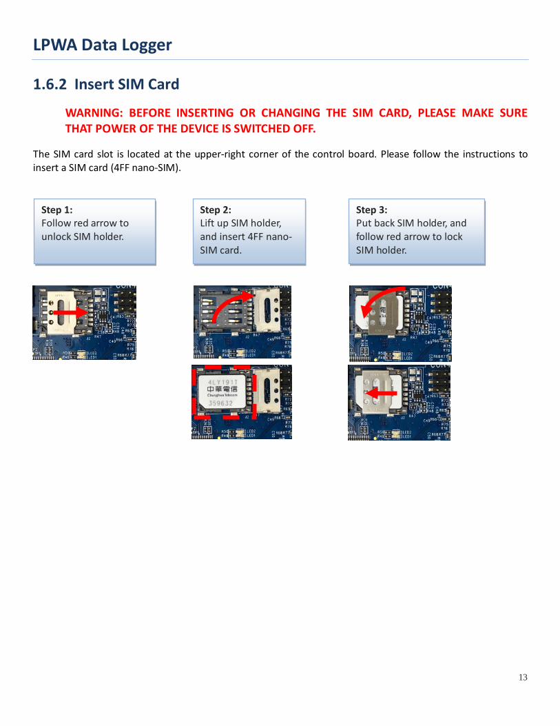
1.6.2 Insert SIM Card
WARNING: BEFORE INSERTING OR CHANGING THE SIM CARD, PLEASE MAKE SURE THAT POWER OF THE DEVICE IS SWITCHED OFF.
The SIM card slot is located at the upper-right corner of the control board. Please follow the instructions to insert a SIM card (4FF nano-SIM).
Step 1: Follow red arrow to unlock SIM holder.
Step 2: Lift up SIM holder, and insert 4FF nano-SIM card.
Step 3: Put back SIM holder, and follow red arrow to lock SIM holder.
LPWA Data Logger
14
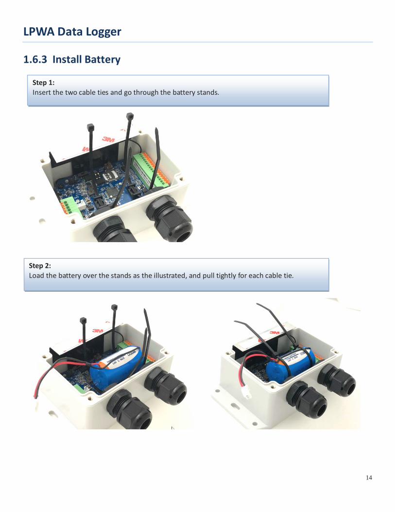
1.6.3 Install Battery
Step 1: Insert the two cable ties and go through the battery stands.
Step 2: Load the battery over the stands as the illustrated, and pull tightly for each cable tie.
LPWA Data Logger
15
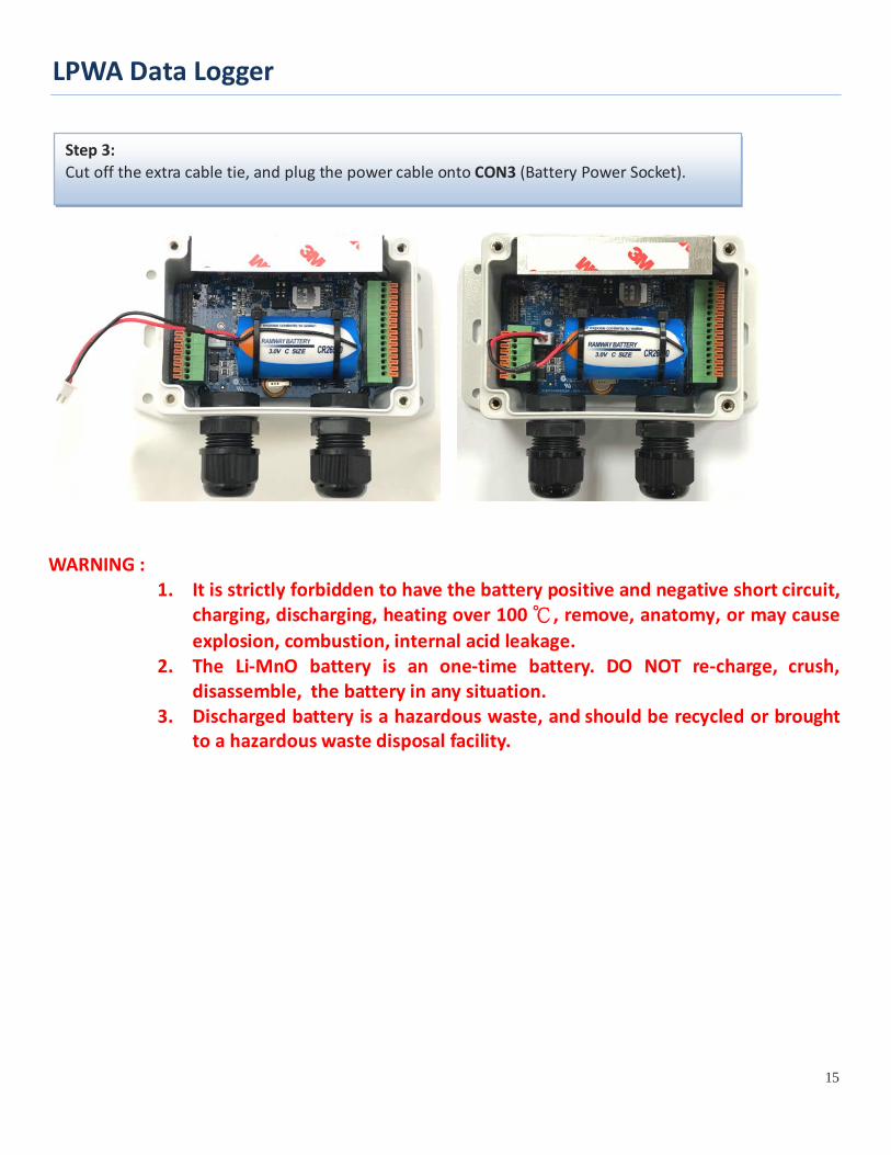
WARNING :
1. It is strictly forbidden to have the battery positive and negative short circuit, charging, discharging, heating over 100 ℃, remove, anatomy, or may cause explosion, combustion, internal acid leakage.
2. The Li-MnO battery is an one-time battery. DO NOT re-charge, crush, disassemble, the battery in any situation.
3. Discharged battery is a hazardous waste, and should be recycled or brought to a hazardous waste disposal facility.
Step 3: Cut off the extra cable tie, and plug the power cable onto CON3 (Battery Power Socket).
LPWA Data Logger
16
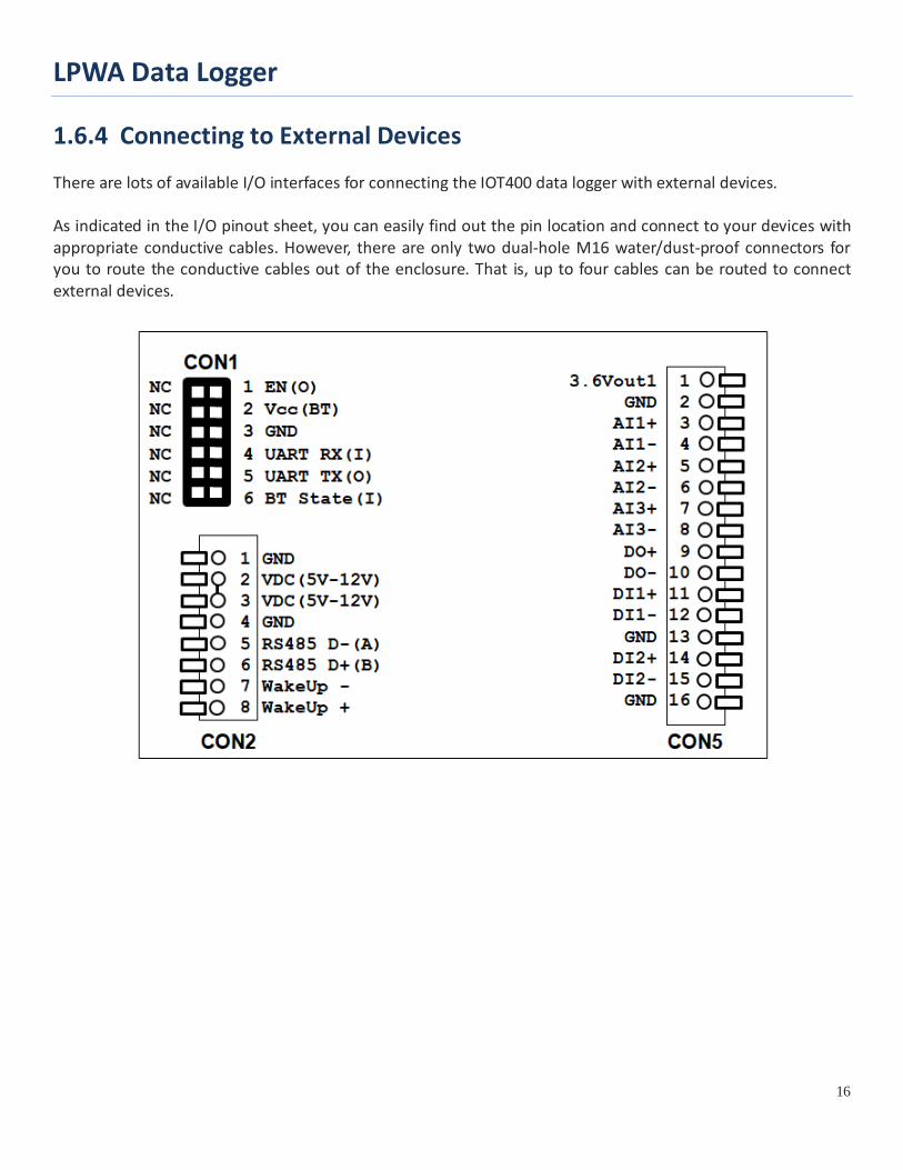
1.6.4 Connecting to External Devices There are lots of available I/O interfaces for connecting the IOT400 data logger with external devices. As indicated in the I/O pinout sheet, you can easily find out the pin location and connect to your devices with appropriate conductive cables. However, there are only two dual-hole M16 water/dust-proof connectors for you to route the conductive cables out of the enclosure. That is, up to four cables can be routed to connect external devices.
LPWA Data Logger
17
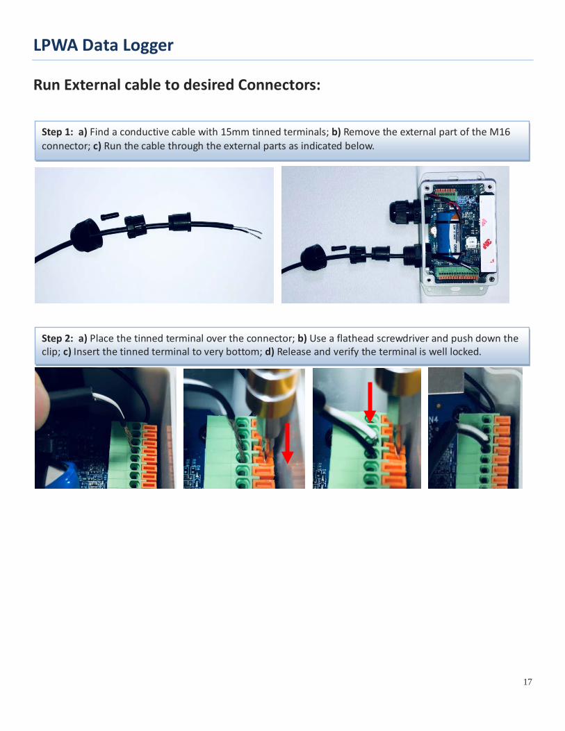
Run External cable to desired Connectors:
Step 1: a) Find a conductive cable with 15mm tinned terminals; b) Remove the external part of the M16 connector; c) Run the cable through the external parts as indicated below.
Step 2: a) Place the tinned terminal over the connector; b) Use a flathead screwdriver and push down the clip; c) Insert the tinned terminal to very bottom; d) Release and verify the terminal is well locked.
LPWA Data Logger
18
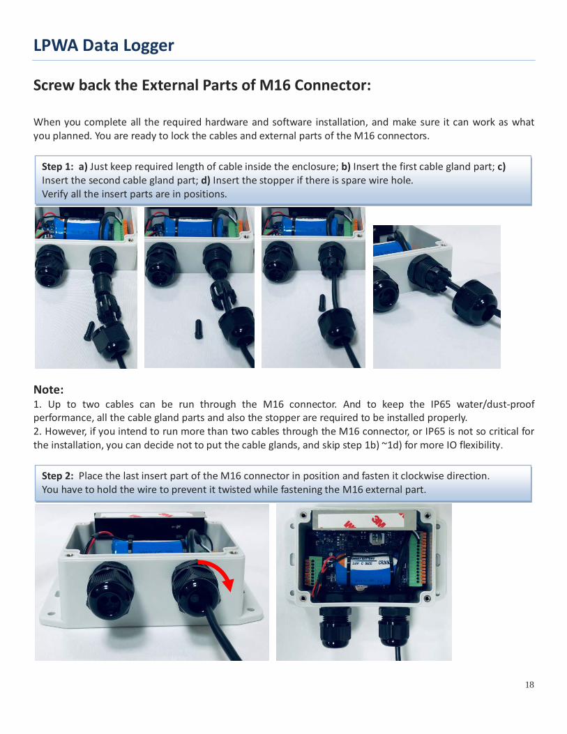
Screw back the External Parts of M16 Connector: When you complete all the required hardware and software installation, and make sure it can work as what you planned. You are ready to lock the cables and external parts of the M16 connectors.
Note: 1. Up to two cables can be run through the M16 connector. And to keep the IP65 water/dust-proof performance, all the cable gland parts and also the stopper are required to be installed properly. 2. However, if you intend to run more than two cables through the M16 connector, or IP65 is not so critical for the installation, you can decide not to put the cable glands, and skip step 1b) ~1d) for more IO flexibility.
Step 1: a) Just keep required length of cable inside the enclosure; b) Insert the first cable gland part; c) Insert the second cable gland part; d) Insert the stopper if there is spare wire hole. Verify all the insert parts are in positions.
Step 2: Place the last insert part of the M16 connector in position and fasten it clockwise direction. You have to hold the wire to prevent it twisted while fastening the M16 external part.
LPWA Data Logger
19
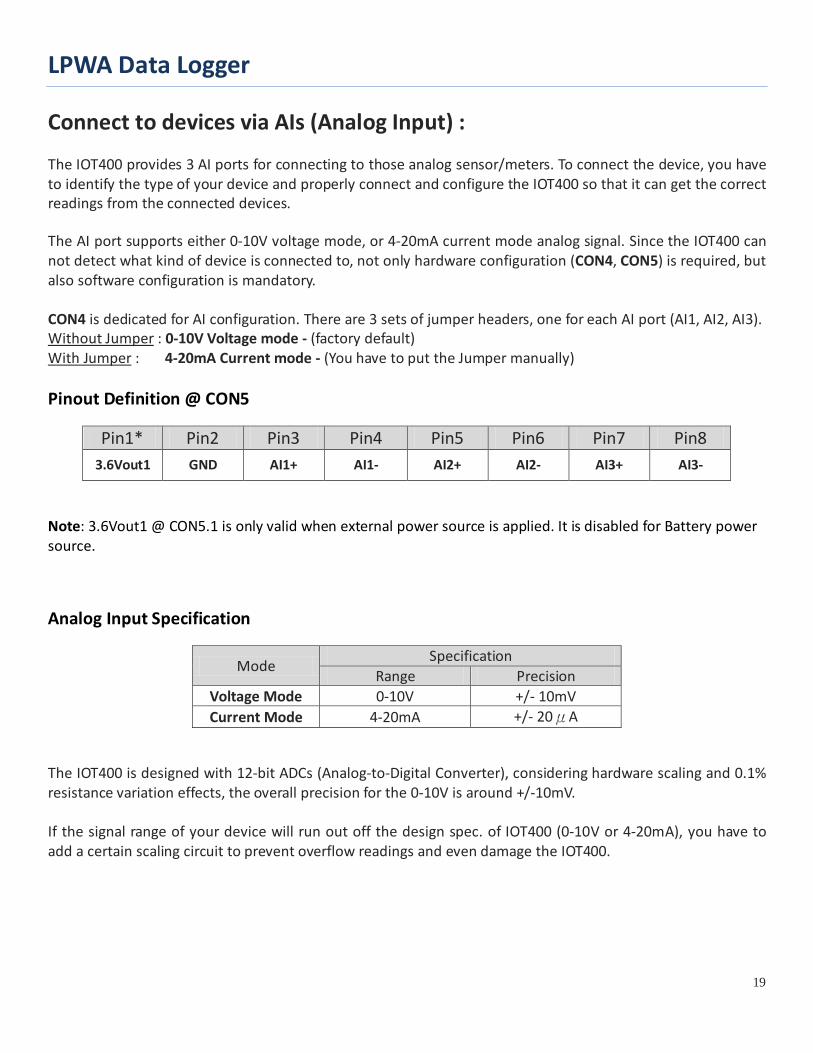
Connect to devices via AIs (Analog Input) : The IOT400 provides 3 AI ports for connecting to those analog sensor/meters. To connect the device, you have to identify the type of your device and properly connect and configure the IOT400 so that it can get the correct readings from the connected devices. The AI port supports either 0-10V voltage mode, or 4-20mA current mode analog signal. Since the IOT400 can not detect what kind of device is connected to, not only hardware configuration (CON4, CON5) is required, but also software configuration is mandatory. CON4 is dedicated for AI configuration. There are 3 sets of jumper headers, one for each AI port (AI1, AI2, AI3). Without Jumper : 0-10V Voltage mode - (factory default) With Jumper : 4-20mA Current mode - (You have to put the Jumper manually) Pinout Definition @ CON5
Pin1* Pin2 Pin3 Pin4 Pin5 Pin6 Pin7 Pin8 3.6Vout1 GND AI1+ AI1- AI2+ AI2- AI3+ AI3-
Note: 3.6Vout1 @ CON5.1 is only valid when external power source is applied. It is disabled for Battery power source.
Analog Input Specification
Mode Specification
Range Precision Voltage Mode 0-10V +/- 10mV Current Mode 4-20mA +/- 20μA
The IOT400 is designed with 12-bit ADCs (Analog-to-Digital Converter), considering hardware scaling and 0.1% resistance variation effects, the overall precision for the 0-10V is around +/-10mV. If the signal range of your device will run out off the design spec. of IOT400 (0-10V or 4-20mA), you have to add a certain scaling circuit to prevent overflow readings and even damage the IOT400.
LPWA Data Logger
20
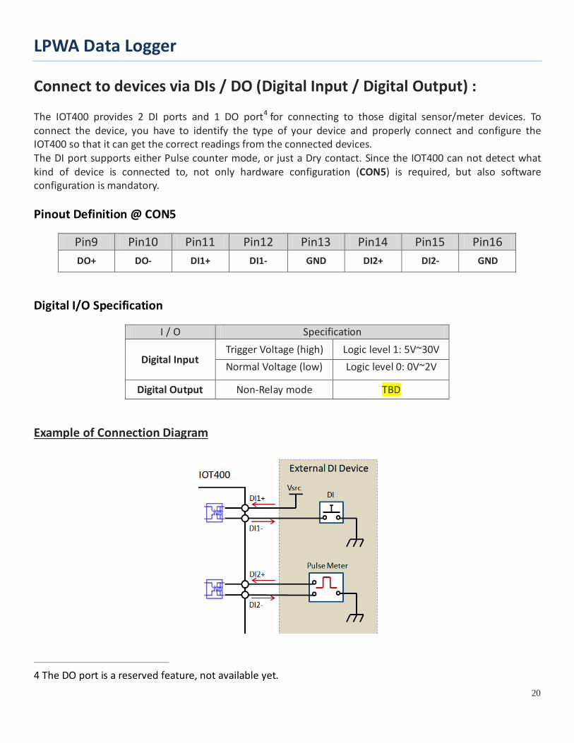
Connect to devices via DIs / DO (Digital Input / Digital Output) : The IOT400 provides 2 DI ports and 1 DO port4 for connecting to those digital sensor/meter devices. To connect the device, you have to identify the type of your device and properly connect and configure the IOT400 so that it can get the correct readings from the connected devices. The DI port supports either Pulse counter mode, or just a Dry contact. Since the IOT400 can not detect what kind of device is connected to, not only hardware configuration (CON5) is required, but also software configuration is mandatory. Pinout Definition @ CON5
Pin9 Pin10 Pin11 Pin12 Pin13 Pin14 Pin15 Pin16 DO+ DO- DI1+ DI1- GND DI2+ DI2- GND
Digital I/O Specification
I / O Specification
Digital Input Trigger Voltage (high) Logic level 1: 5V~30V Normal Voltage (low) Logic level 0: 0V~2V
Digital Output Non-Relay mode TBD
Example of Connection Diagram
4 The DO port is a reserved feature, not available yet.
LPWA Data Logger
21
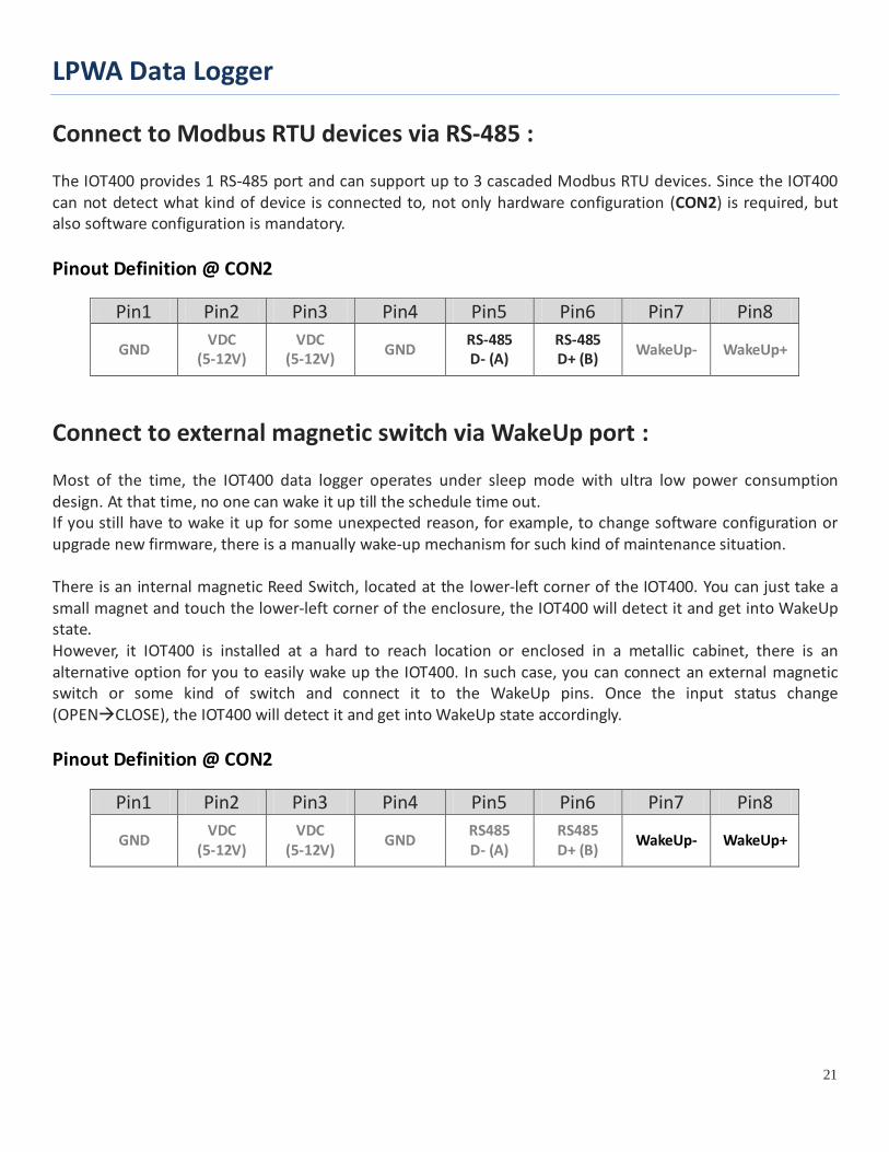
Connect to Modbus RTU devices via RS-485 : The IOT400 provides 1 RS-485 port and can support up to 3 cascaded Modbus RTU devices. Since the IOT400 can not detect what kind of device is connected to, not only hardware configuration (CON2) is required, but also software configuration is mandatory. Pinout Definition @ CON2
Pin1 Pin2 Pin3 Pin4 Pin5 Pin6 Pin7 Pin8
GND VDC (5-12V)
VDC (5-12V) GND RS-485
D- (A) RS-485 D+ (B) WakeUp- WakeUp+
Connect to external magnetic switch via WakeUp port : Most of the time, the IOT400 data logger operates under sleep mode with ultra low power consumption design. At that time, no one can wake it up till the schedule time out. If you still have to wake it up for some unexpected reason, for example, to change software configuration or upgrade new firmware, there is a manually wake-up mechanism for such kind of maintenance situation. There is an internal magnetic Reed Switch, located at the lower-left corner of the IOT400. You can just take a small magnet and touch the lower-left corner of the enclosure, the IOT400 will detect it and get into WakeUp state. However, it IOT400 is installed at a hard to reach location or enclosed in a metallic cabinet, there is an alternative option for you to easily wake up the IOT400. In such case, you can connect an external magnetic switch or some kind of switch and connect it to the WakeUp pins. Once the input status change (OPENCLOSE), the IOT400 will detect it and get into WakeUp state accordingly. Pinout Definition @ CON2
Pin1 Pin2 Pin3 Pin4 Pin5 Pin6 Pin7 Pin8
GND VDC (5-12V)
VDC (5-12V) GND RS485
D- (A) RS485 D+ (B) WakeUp- WakeUp+
LPWA Data Logger
22
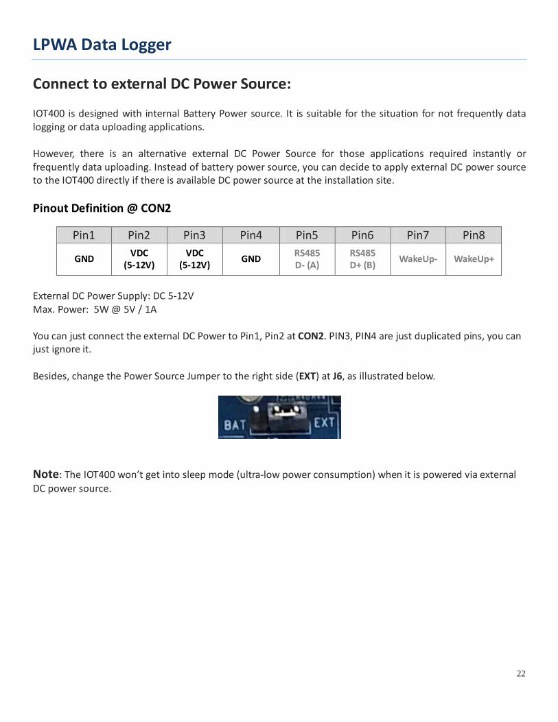
Connect to external DC Power Source: IOT400 is designed with internal Battery Power source. It is suitable for the situation for not frequently data logging or data uploading applications. However, there is an alternative external DC Power Source for those applications required instantly or frequently data uploading. Instead of battery power source, you can decide to apply external DC power source to the IOT400 directly if there is available DC power source at the installation site. Pinout Definition @ CON2
Pin1 Pin2 Pin3 Pin4 Pin5 Pin6 Pin7 Pin8
GND VDC (5-12V)
VDC (5-12V) GND RS485
D- (A) RS485 D+ (B) WakeUp- WakeUp+
External DC Power Supply: DC 5-12V Max. Power: 5W @ 5V / 1A You can just connect the external DC Power to Pin1, Pin2 at CON2. PIN3, PIN4 are just duplicated pins, you can just ignore it. Besides, change the Power Source Jumper to the right side (EXT) at J6, as illustrated below.
Note: The IOT400 won’t get into sleep mode (ultra-low power consumption) when it is powered via external DC power source.
LPWA Data Logger
23
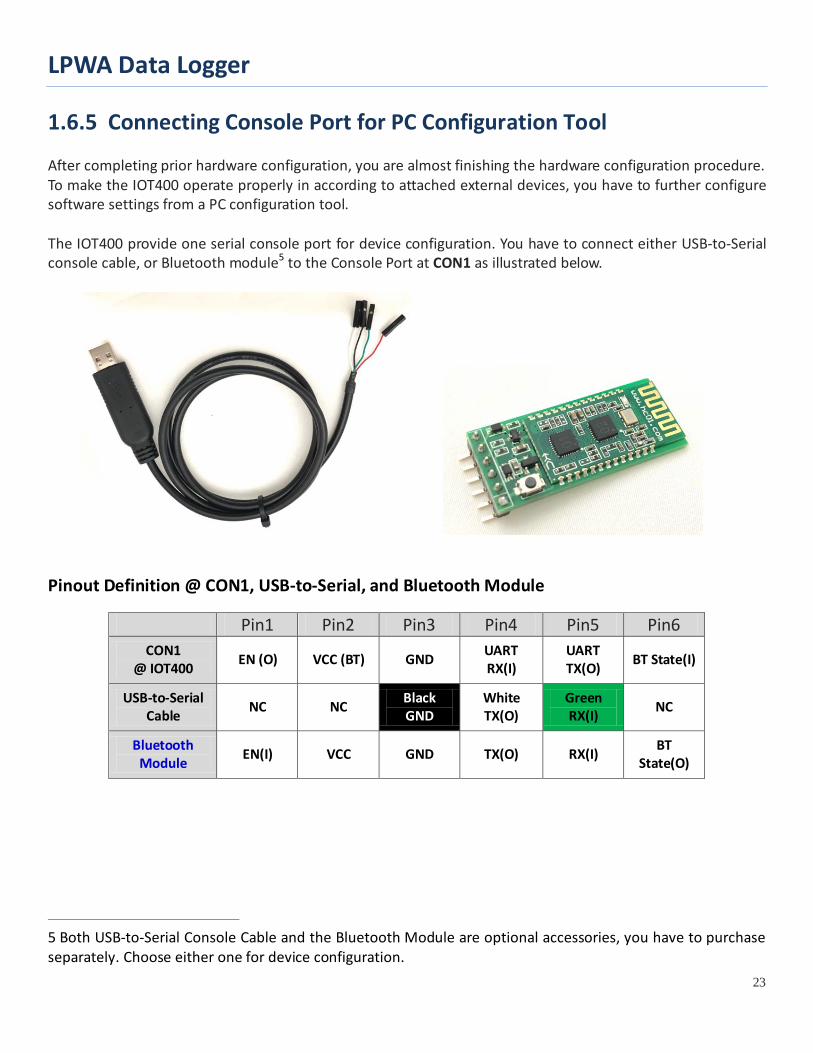
1.6.5 Connecting Console Port for PC Configuration Tool After completing prior hardware configuration, you are almost finishing the hardware configuration procedure. To make the IOT400 operate properly in according to attached external devices, you have to further configure software settings from a PC configuration tool. The IOT400 provide one serial console port for device configuration. You have to connect either USB-to-Serial console cable, or Bluetooth module5 to the Console Port at CON1 as illustrated below.
Pinout Definition @ CON1, USB-to-Serial, and Bluetooth Module
Pin1 Pin2 Pin3 Pin4 Pin5 Pin6 CON1
@ IOT400 EN (O) VCC (BT) GND UART RX(I)
UART TX(O) BT State(I)
USB-to-Serial Cable NC NC Black
GND White TX(O)
Green RX(I) NC
Bluetooth Module EN(I) VCC GND TX(O) RX(I) BT
State(O)
5 Both USB-to-Serial Console Cable and the Bluetooth Module are optional accessories, you have to purchase separately. Choose either one for device configuration.
LPWA Data Logger
24
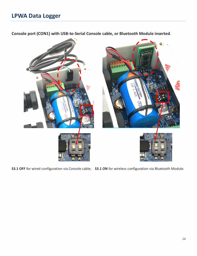
Console port (CON1) with USB-to-Serial Console cable, or Bluetooth Module inserted.
S3.1 OFF for wired configuration via Console cable; S3.1 ON for wireless configuration via Bluetooth Module.
LPWA Data Logger
25
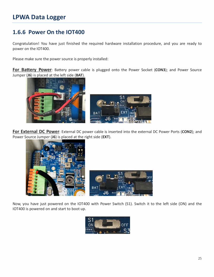
1.6.6 Power On the IOT400 Congratulation! You have just finished the required hardware installation procedure, and you are ready to power on the IOT400. Please make sure the power source is properly installed: For Battery Power: Battery power cable is plugged onto the Power Socket (CON3); and Power Source Jumper (J6) is placed at the left side (BAT).
For External DC Power: External DC power cable is inserted into the external DC Power Ports (CON2); and Power Source Jumper (J6) is placed at the right side (EXT).
Now, you have just powered on the IOT400 with Power Switch (S1). Switch it to the left side (ON) and the IOT400 is powered on and start to boot up.
LPWA Data Logger
26
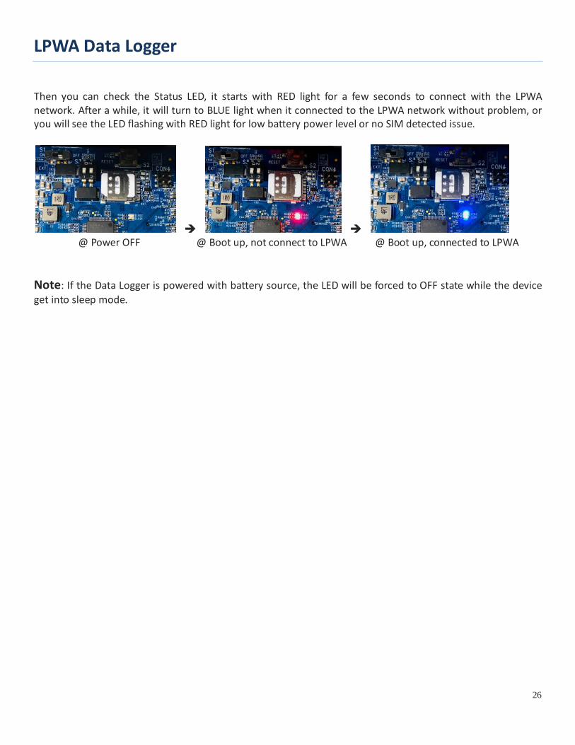
Then you can check the Status LED, it starts with RED light for a few seconds to connect with the LPWA network. After a while, it will turn to BLUE light when it connected to the LPWA network without problem, or you will see the LED flashing with RED light for low battery power level or no SIM detected issue.
@ Power OFF @ Boot up, not connect to LPWA @ Boot up, connected to LPWA
Note: If the Data Logger is powered with battery source, the LED will be forced to OFF state while the device get into sleep mode.
LPWA Data Logger
27
1.6.7 Setup with Windows-based Configuration Tool
The IOT400 series product has to be configured with a Windows configuration tool. Just find out a PC/NB with an available USB port, and plug in the USB-to-Serial console cable into it; or use a Bluetooth enable NB to configure the IOT400 wirelessly.
For the first time to setup the IOT400 with his Configuration Tools, you have to download it from the vendor provided URLs or QR-code, and install it to the PC/NB for further device configuration.
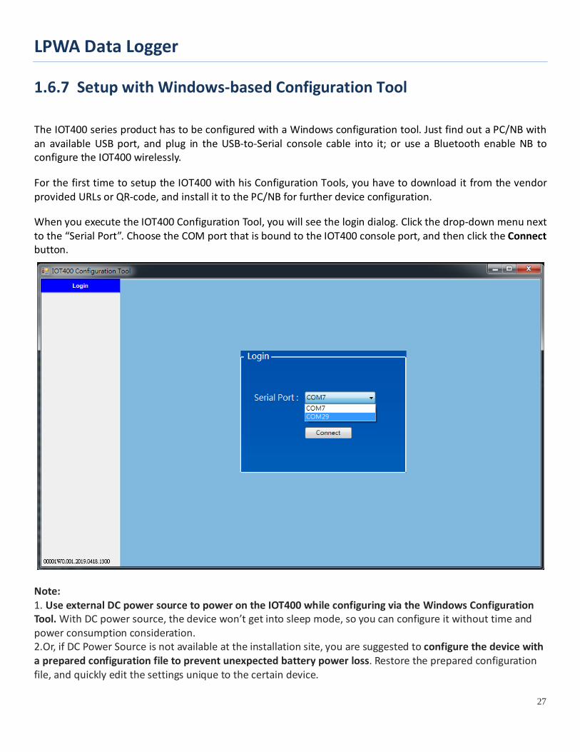
When you execute the IOT400 Configuration Tool, you will see the login dialog. Click the drop-down menu next to the “Serial Port”. Choose the COM port that is bound to the IOT400 console port, and then click the Connect button.
Note: 1. Use external DC power source to power on the IOT400 while configuring via the Windows Configuration Tool. With DC power source, the device won’t get into sleep mode, so you can configure it without time and power consumption consideration. 2.Or, if DC Power Source is not available at the installation site, you are suggested to configure the device with a prepared configuration file to prevent unexpected battery power loss. Restore the prepared configuration file, and quickly edit the settings unique to the certain device.
LPWA Data Logger
28
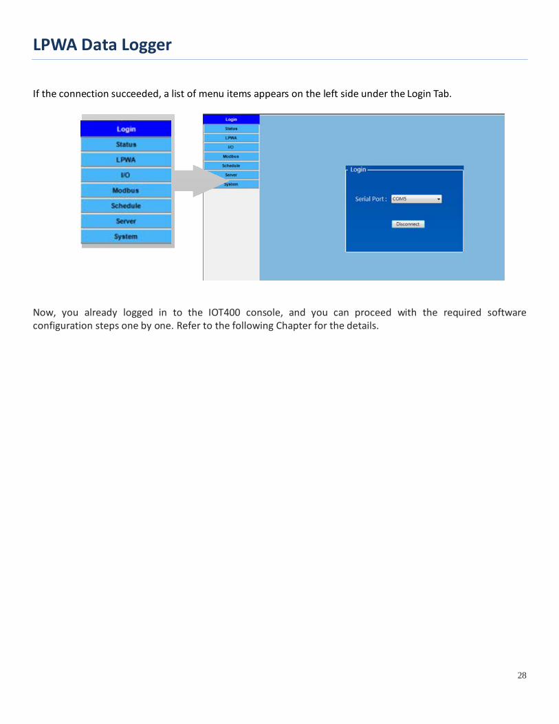
If the connection succeeded, a list of menu items appears on the left side under the Login Tab.
Now, you already logged in to the IOT400 console, and you can proceed with the required software configuration steps one by one. Refer to the following Chapter for the details.
LPWA Data Logger
29
1.6.8 Device Mount and Screw Back the Top Cover
The IOT400 series product has to be configured with a Windows configuration tool. Just find out a PC/NB with an available USB port, and plug in the USB-to-Serial console cable into it; or use a Bluetooth-enabled NB to configure the IOT400 wirelessly.
After you finished all the software configurations, you are ready to free the IOT400 and make it operate as expected. You have to take the following actions for it.
4. Power Off the IOT400, and remove the console cable / Bluetooth Module.
5. Mount the IOT400 base enclosure on the planned location.
6. Make sure all the wiring cables are running in position through the M16 connectors;
7. Fasten tightly the external parts on the M16 connectors, holding the internal cables to prevent from twisted along with the cable gland with care.
8. Power On the IOT400, and wait until the Status LED becomes BLUE light to make sure it connected to LPWA network.
9. Screw back the Top cover with care. Make sure the surrounding rubber pad is in position everywhere to keep the IP65 performance for water and dust proof.
LPWA Data Logger
30
Chapter 2 Device Configuration
2.1 Device Status
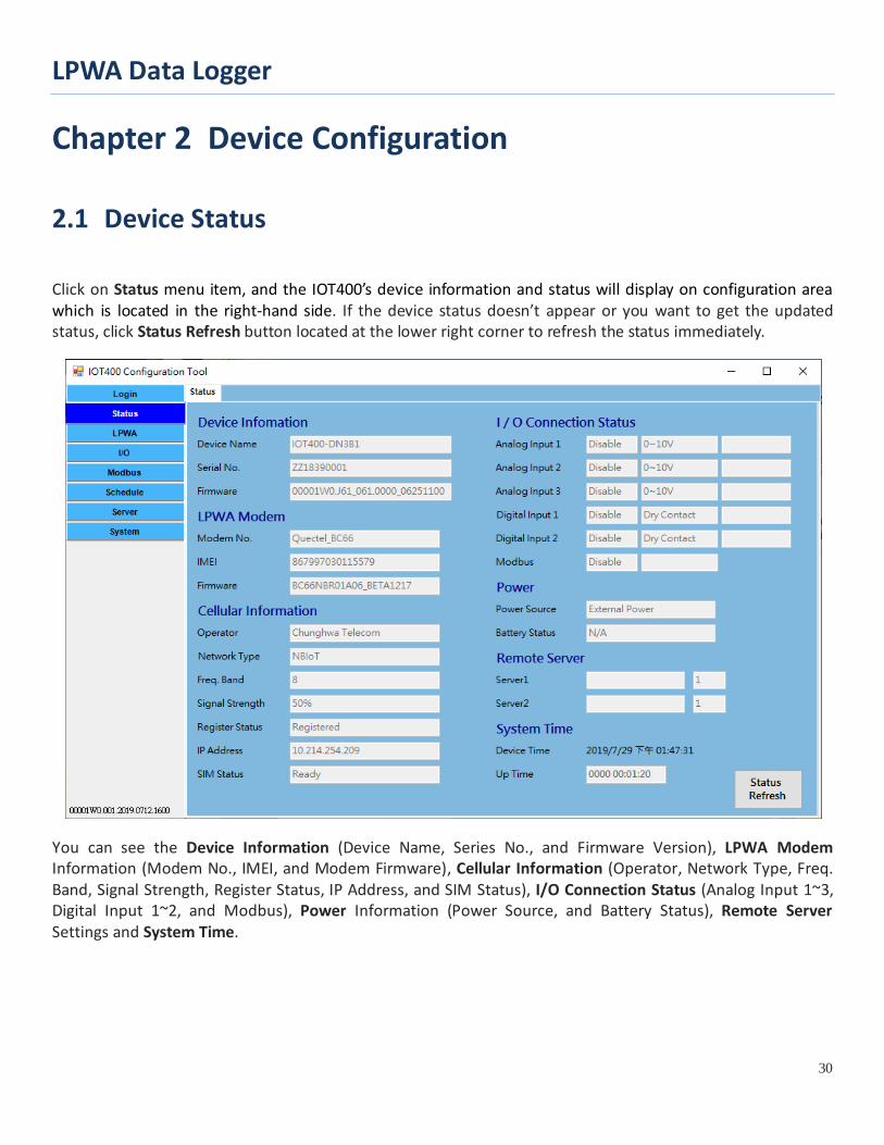
Click on Status menu item, and the IOT400’s device information and status will display on configuration area which is located in the right-hand side. If the device status doesn’t appear or you want to get the updated status, click Status Refresh button located at the lower right corner to refresh the status immediately.
You can see the Device Information (Device Name, Series No., and Firmware Version), LPWA Modem Information (Modem No., IMEI, and Modem Firmware), Cellular Information (Operator, Network Type, Freq. Band, Signal Strength, Register Status, IP Address, and SIM Status), I/O Connection Status (Analog Input 1~3, Digital Input 1~2, and Modbus), Power Information (Power Source, and Battery Status), Remote Server Settings and System Time.
LPWA Data Logger
31
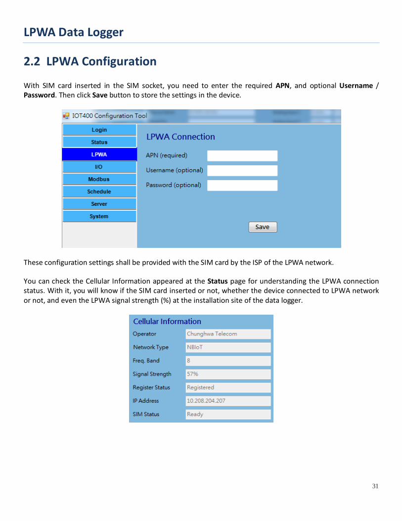
2.2 LPWA Configuration With SIM card inserted in the SIM socket, you need to enter the required APN, and optional Username / Password. Then click Save button to store the settings in the device.
These configuration settings shall be provided with the SIM card by the ISP of the LPWA network. You can check the Cellular Information appeared at the Status page for understanding the LPWA connection status. With it, you will know if the SIM card inserted or not, whether the device connected to LPWA network or not, and even the LPWA signal strength (%) at the installation site of the data logger.
LPWA Data Logger
32
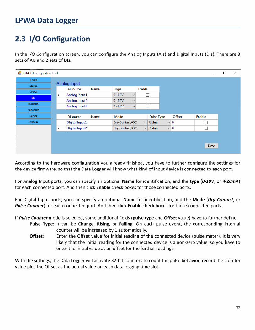
2.3 I/O Configuration In the I/O Configuration screen, you can configure the Analog Inputs (AIs) and Digital Inputs (DIs). There are 3 sets of AIs and 2 sets of DIs.
According to the hardware configuration you already finished, you have to further configure the settings for the device firmware, so that the Data Logger will know what kind of input device is connected to each port. For Analog Input ports, you can specify an optional Name for identification, and the type (0-10V, or 4-20mA) for each connected port. And then click Enable check boxes for those connected ports. For Digital Input ports, you can specify an optional Name for identification, and the Mode (Dry Contact, or Pulse Counter) for each connected port. And then click Enable check boxes for those connected ports. If Pulse Counter mode is selected, some additional fields (pulse type and Offset value) have to further define.
Pulse Type: It can be Change, Rising, or Falling. On each pulse event, the corresponding internal counter will be increased by 1 automatically.
Offset: Enter the Offset value for initial reading of the connected device (pulse meter). It is very likely that the initial reading for the connected device is a non-zero value, so you have to enter the initial value as an offset for the further readings.
With the settings, the Data Logger will activate 32-bit counters to count the pulse behavior, record the counter value plus the Offset as the actual value on each data logging time slot.
LPWA Data Logger
33
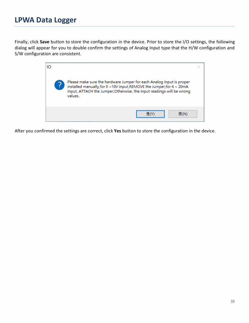
Finally, click Save button to store the configuration in the device. Prior to store the I/O settings, the following dialog will appear for you to double confirm the settings of Analog Input type that the H/W configuration and S/W configuration are consistent.
After you confirmed the settings are correct, click Yes button to store the configuration in the device.
LPWA Data Logger
34
2.4 Modbus Configuration
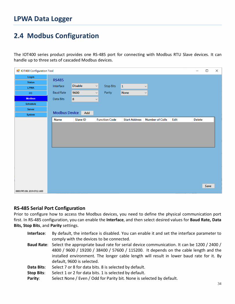
The IOT400 series product provides one RS-485 port for connecting with Modbus RTU Slave devices. It can handle up to three sets of cascaded Modbus devices.
RS-485 Serial Port Configuration Prior to configure how to access the Modbus devices, you need to define the physical communication port first. In RS-485 configuration, you can enable the Interface, and then select desired values for Baud Rate, Data Bits, Stop Bits, and Parity settings.
Interface: By default, the interface is disabled. You can enable it and set the interface parameter to comply with the devices to be connected.
Baud Rate: Select the appropriate baud rate for serial device communication. It can be 1200 / 2400 / 4800 / 9600 / 19200 / 38400 / 57600 / 115200. It depends on the cable length and the installed environment. The longer cable length will result in lower baud rate for it. By default, 9600 is selected.
Data Bits: Select 7 or 8 for data bits. 8 is selected by default. Stop Bits: Select 1 or 2 for data bits. 1 is selected by default. Parity: Select None / Even / Odd for Parity bit. None is selected by default.
LPWA Data Logger
35
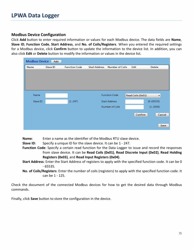
Modbus Device Configuration Click Add button to enter required information or values for each Modbus device. The data fields are Name, Slave ID, Function Code, Start Address, and No. of Coils/Registers. When you entered the required settings for a Modbus device, click Confirm button to update the information to the device list. In addition, you can also click Edit or Delete button to modify the information or values in the device list.
Name: Enter a name as the identifier of the Modbus RTU slave device. Slave ID: Specify a unique ID for the slave device. It can be 1 - 247. Function Code: Specify a certain read function for the Data Logger to issue and record the responses
from slave device. It can be Read Coils (0x01), Read Discrete Input (0x02), Read Holding Registers (0x03), and Read Input Registers (0x04).
Start Address: Enter the Start Address of registers to apply with the specified function code. It can be 0 - 65535.
No. of Coils/Registers: Enter the number of coils (registers) to apply with the specified function code. It can be 1 - 125.
Check the document of the connected Modbus devices for how to get the desired data through Modbus commands. Finally, click Save button to store the configuration in the device.
LPWA Data Logger
36
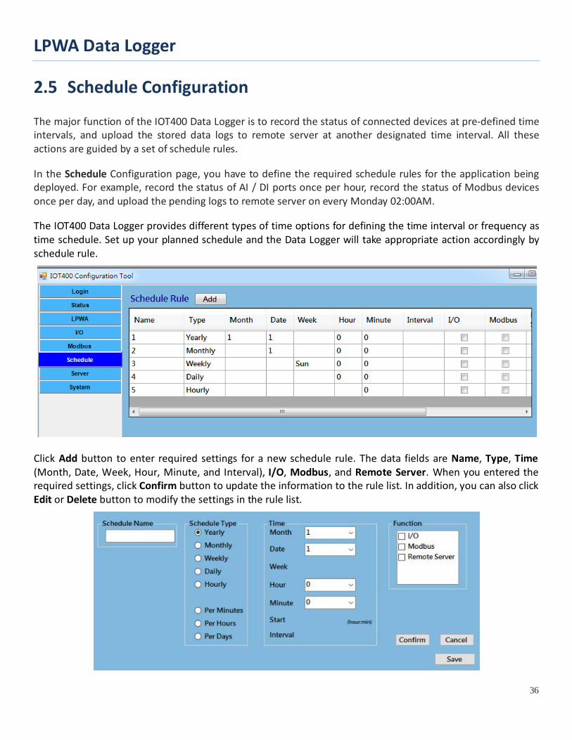
2.5 Schedule Configuration The major function of the IOT400 Data Logger is to record the status of connected devices at pre-defined time intervals, and upload the stored data logs to remote server at another designated time interval. All these actions are guided by a set of schedule rules.
In the Schedule Configuration page, you have to define the required schedule rules for the application being deployed. For example, record the status of AI / DI ports once per hour, record the status of Modbus devices once per day, and upload the pending logs to remote server on every Monday 02:00AM.
The IOT400 Data Logger provides different types of time options for defining the time interval or frequency as time schedule. Set up your planned schedule and the Data Logger will take appropriate action accordingly by schedule rule.
Click Add button to enter required settings for a new schedule rule. The data fields are Name, Type, Time (Month, Date, Week, Hour, Minute, and Interval), I/O, Modbus, and Remote Server. When you entered the required settings, click Confirm button to update the information to the rule list. In addition, you can also click Edit or Delete button to modify the settings in the rule list.
LPWA Data Logger
37
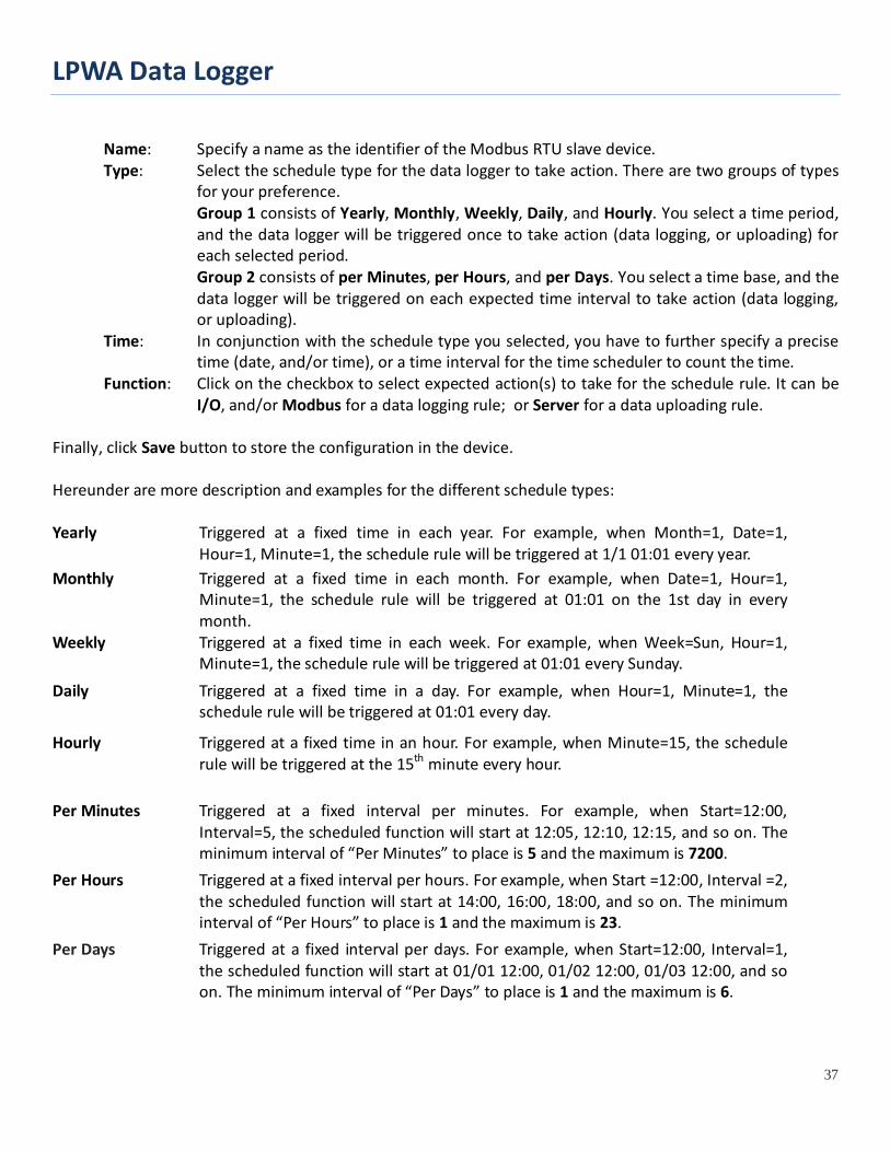
Name: Specify a name as the identifier of the Modbus RTU slave device. Type: Select the schedule type for the data logger to take action. There are two groups of types
for your preference. Group 1 consists of Yearly, Monthly, Weekly, Daily, and Hourly. You select a time period,
and the data logger will be triggered once to take action (data logging, or uploading) for each selected period.
Group 2 consists of per Minutes, per Hours, and per Days. You select a time base, and the data logger will be triggered on each expected time interval to take action (data logging, or uploading).
Time: In conjunction with the schedule type you selected, you have to further specify a precise time (date, and/or time), or a time interval for the time scheduler to count the time.
Function: Click on the checkbox to select expected action(s) to take for the schedule rule. It can be I/O, and/or Modbus for a data logging rule; or Server for a data uploading rule.
Finally, click Save button to store the configuration in the device. Hereunder are more description and examples for the different schedule types: Yearly Triggered at a fixed time in each year. For example, when Month=1, Date=1,
Hour=1, Minute=1, the schedule rule will be triggered at 1/1 01:01 every year. Monthly Triggered at a fixed time in each month. For example, when Date=1, Hour=1,
Minute=1, the schedule rule will be triggered at 01:01 on the 1st day in every month.
Weekly Triggered at a fixed time in each week. For example, when Week=Sun, Hour=1, Minute=1, the schedule rule will be triggered at 01:01 every Sunday.
Daily Triggered at a fixed time in a day. For example, when Hour=1, Minute=1, the schedule rule will be triggered at 01:01 every day.
Hourly Triggered at a fixed time in an hour. For example, when Minute=15, the schedule rule will be triggered at the 15th minute every hour.
Per Minutes Triggered at a fixed interval per minutes. For example, when Start=12:00, Interval=5, the scheduled function will start at 12:05, 12:10, 12:15, and so on. The minimum interval of “Per Minutes” to place is 5 and the maximum is 7200.
Per Hours Triggered at a fixed interval per hours. For example, when Start =12:00, Interval =2, the scheduled function will start at 14:00, 16:00, 18:00, and so on. The minimum interval of “Per Hours” to place is 1 and the maximum is 23.
Per Days Triggered at a fixed interval per days. For example, when Start=12:00, Interval=1, the scheduled function will start at 01/01 12:00, 01/02 12:00, 01/03 12:00, and so on. The minimum interval of “Per Days” to place is 1 and the maximum is 6.
LPWA Data Logger
38
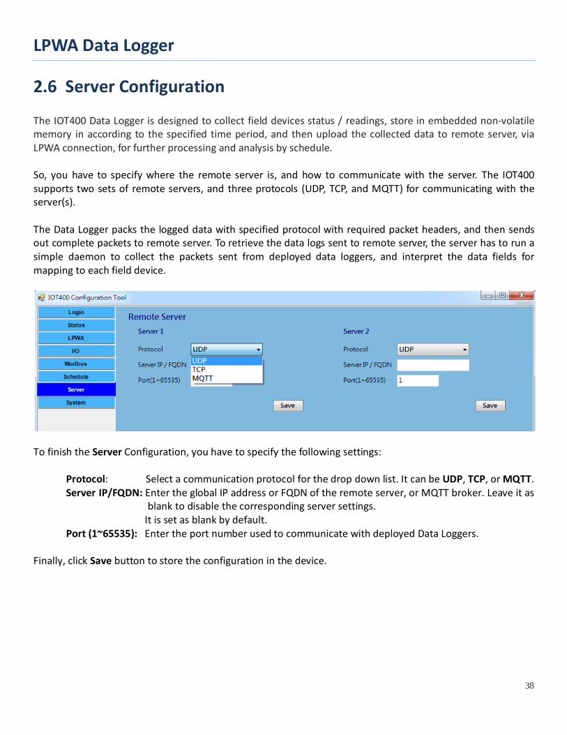
2.6 Server Configuration The IOT400 Data Logger is designed to collect field devices status / readings, store in embedded non-volatile memory in according to the specified time period, and then upload the collected data to remote server, via LPWA connection, for further processing and analysis by schedule. So, you have to specify where the remote server is, and how to communicate with the server. The IOT400 supports two sets of remote servers, and three protocols (UDP, TCP, and MQTT) for communicating with the server(s). The Data Logger packs the logged data with specified protocol with required packet headers, and then sends out complete packets to remote server. To retrieve the data logs sent to remote server, the server has to run a simple daemon to collect the packets sent from deployed data loggers, and interpret the data fields for mapping to each field device.
To finish the Server Configuration, you have to specify the following settings:
Protocol: Select a communication protocol for the drop down list. It can be UDP, TCP, or MQTT. Server IP/FQDN: Enter the global IP address or FQDN of the remote server, or MQTT broker. Leave it as
blank to disable the corresponding server settings. It is set as blank by default.
Port (1~65535): Enter the port number used to communicate with deployed Data Loggers. Finally, click Save button to store the configuration in the device.
LPWA Data Logger
39
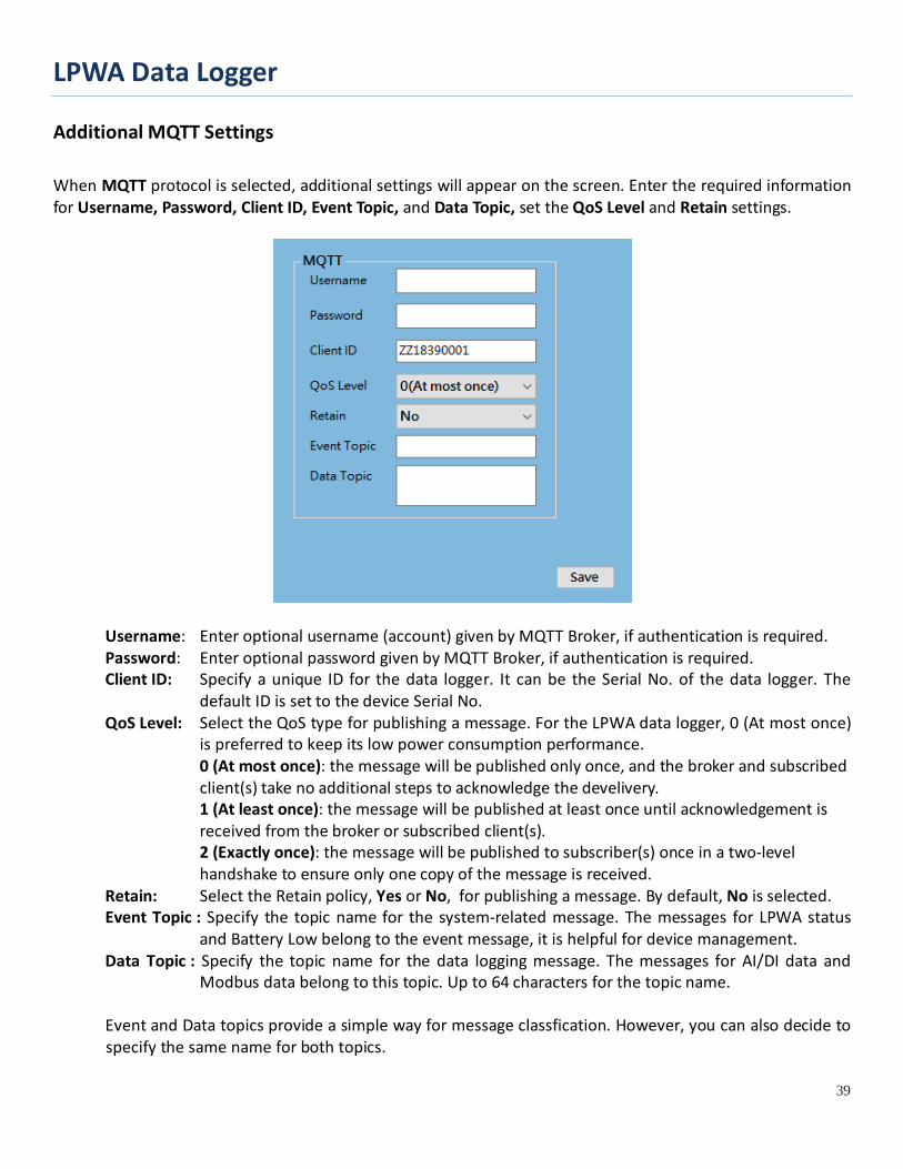
Additional MQTT Settings
When MQTT protocol is selected, additional settings will appear on the screen. Enter the required information for Username, Password, Client ID, Event Topic, and Data Topic, set the QoS Level and Retain settings.
Username: Enter optional username (account) given by MQTT Broker, if authentication is required. Password: Enter optional password given by MQTT Broker, if authentication is required. Client ID: Specify a unique ID for the data logger. It can be the Serial No. of the data logger. The
default ID is set to the device Serial No. QoS Level: Select the QoS type for publishing a message. For the LPWA data logger, 0 (At most once)
is preferred to keep its low power consumption performance. 0 (At most once): the message will be published only once, and the broker and subscribed client(s) take no additional steps to acknowledge the develivery. 1 (At least once): the message will be published at least once until acknowledgement is received from the broker or subscribed client(s). 2 (Exactly once): the message will be published to subscriber(s) once in a two-level handshake to ensure only one copy of the message is received.
Retain: Select the Retain policy, Yes or No, for publishing a message. By default, No is selected. Event Topic : Specify the topic name for the system-related message. The messages for LPWA status
and Battery Low belong to the event message, it is helpful for device management. Data Topic : Specify the topic name for the data logging message. The messages for AI/DI data and
Modbus data belong to this topic. Up to 64 characters for the topic name. Event and Data topics provide a simple way for message classfication. However, you can also decide to specify the same name for both topics.
LPWA Data Logger
40
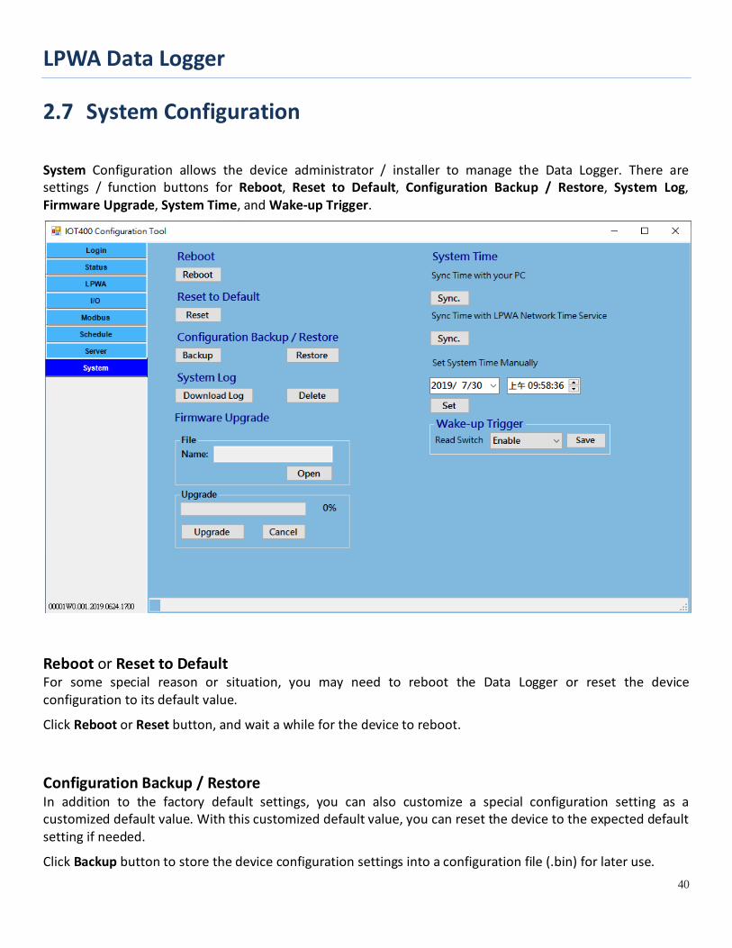
2.7 System Configuration
System Configuration allows the device administrator / installer to manage the Data Logger. There are settings / function buttons for Reboot, Reset to Default, Configuration Backup / Restore, System Log, Firmware Upgrade, System Time, and Wake-up Trigger.
Reboot or Reset to Default For some special reason or situation, you may need to reboot the Data Logger or reset the device configuration to its default value.
Click Reboot or Reset button, and wait a while for the device to reboot.
Configuration Backup / Restore In addition to the factory default settings, you can also customize a special configuration setting as a customized default value. With this customized default value, you can reset the device to the expected default setting if needed.
Click Backup button to store the device configuration settings into a configuration file (.bin) for later use.
LPWA Data Logger
41
Click Restore button to restore the device settings to a certain backup copy, or quickly duplicate a device’s configuration file to the other devices with the same configuration for a certain application. In such case, ensure to set the unique Device ID for separate devices.
System Log For some device maintenance purpose, you may need to get the system log for troubleshooting. You can do it through the configuration tool, click Download Log or Delete button.
Click Download Log button to store the System Log into a log file (.txt) for troubleshooting.
Click Delete button to erase the existing system logs. Please use the delete function with care, all the device system log, including data log will be erased. If required, download log first and then delete out-of-date log.
Firmware Upgrade If new firmware is available, you can manually upgrade it for feature enhancement or bug resolving.
Click Open button to indentify the file location / file name of the new firmware image (.bin).
Click Upgrade button to start upgrading the new firmware to the device. DO NOT turn off the Data Logger, or disconnect the console cable while upgrading new firmware, it is very likely to damage the device.
Once the Firmware Upgrade completed, the device will be reboot with the new firmware immediately.
System Time System time is a vital element for the Data Logger. Both data logging and data uploading tasks need to be triggered at a certain time. You have to make sure the Data Logger is configured with correct time settings.
There are three approaches for initial settings. You can simple click Sync. button to synchronize the Data Logger’s time with your PC that is running the configuration tool, or synchronize it with the LPWA network time service. Besides, you can also set the date and time for the Data Logger manually.
Wake-Up Trigger Most of the time, the IOT400 data logger operates under sleep mode with ultra low power consumption design. At that time, no one can wake it up till the schedule time out. However, there is a manually Wake-Up Trigger mechanism for you to wake up the data logger for some unexpected reason, for example, to change software configuration or upgrade new firmware. By default the Reed Switch Wake-Up Trigger is enabled. The Reed Switch is located at the lower-left corner of the IOT400. You can just take a small magnet and touch the lower-left corner of the enclosure, the IOT400 will detect it and get into WakeUp state.
LPWA Data Logger
42
Chapter 3 Data Logs
According to the defined schedule rules, the Data Logger will log the status of the connected devices (AIs, DIs, and Modbus) in non-volatile storage, and upload those pending logs to specified remote server(s).
When the remote server (UDP / TCP / MQTT protocols) received the packets of data logs, it can easily get the payload, interpret the data fields, and then import the data to the application database for further processing.
3.1 Data Log Format
Each data log entry is composed with a formatted string, followed with CR / LF characters.
SerialNo DateTime LogType:Data
SerialNo : Serial no. for the device that sent the data log. DateTime: The recorded time for the following data log. LogType: The type of the following data. It can be IO, M1, M2, and M3. Each log type will be
follow with different data format. Besides, there are some non-data LogType event logs for management purpose. It
can be EB (Battery Low), EN (Uplink Network), EP (Power ON), and EW (Device WakeUp).
Data: The actual data for the corresponding type of device.
Data Format of IO: IO:TypeVal1,TypeVal2,TypeVal3,TypeVal4,TypeVal5
The Data Logger provides five Input ports. Each time the IO schedule rule triggered, the port type and status for all the five ports will be recorded as the data log simultaneously in an IO record.
TypeVal1~5 : One character for the type, V for 0-10V Voltage mode; A for 4-20mA Current mode; D for Dry Contact; and P for Pulse Counter.
Followed by a value for each port. A certain TypeVal will be skipped if it is a disabled port.
For examples,
“IO:V1.10,A12.50,V3.30,D1,P1234” stands for it is a log entry from Input ports, where Port A1 is 1.10Volt, A2 is 12.50mA, AI3 is 3.3Volt, D1 is at ‘1’ for HIGH, D2 counter reading is 1234.
“IO:V1.10,,,D0,” stands for it is a log entry from Input ports, where Port A1 is 1.10Volt, D1 is at ‘0’ for LOW. In
LPWA Data Logger
43
this case, AI2, AI3, and D2 are missing because they are disabled.
Data Format of M1, M2, M3:
M1:ID,FC,ADDR,LEN:Val
M2:ID,FC,ADDR,LEN:Val
M3:ID,FC,ADDR,LEN:Val
The Data Logger supports up to three Modbus RTU devices. Each time the Modbus schedule rule triggered, the specified device status will be recorded as the data log in individual M1/M2/M3 record sequentially.
ID : The Modbus ID for the corresponding Modus device. FC : The function code issued to get the Modbus data. ADDR : The start address for getting the Modbus data. LEN : The no. of coils/registers for getting the Modbus data. Val : The recorded Modbus data that is retrieved with specified command.
For examples,
“M1:1,1,0,32:01020304” stands for it is a log entry from the first Modbus device, where Modbus ID is 1, Function Code is 1, Start address is 0, no. of Coils is 32(bits), data string is 01020304.
“M2:2,2,1,1:00” stands for it is a log entry from the second Modbus device, where Modbus ID is 2, Function Code is 2, Start address is 1, no. of Coils is 1(bit), data string is 00.
“M3:10,3,2,3:010102020303” stands for it is a log entry from the second Modbus device, where Modbus ID is 10, Function Code is 2, Start address is 2, no. of Registers is 3(word), data string is 010102020303.
LPWA Data Logger
44
Data Format of EB, EN, EP, EW:
TBD
For device management purpose, the Data Logger will also record some important device activities as event logs, and uploading to remote server in according to the schedule rule. The types of event logs can be EB (Battery Low), EN (Uplink Connection), EP (Power ON), and EW (Device WakeUp).