lrfd for micropiles
DESCRIPTION
An overview of LRFD for micropiles including a design example with comparison between SLD methods and AASHTO LRFD. Presented at 2011 ADSC / DFI Micropile Seminar in Little Rock, AR.TRANSCRIPT

L d d R i t F tLoad and Resistance Factor Design (LRFD) for Micropilesg ( ) p
Jonathan Bennett, PE, D.GE – Chief Engineer
May 4, 2011

LRFD??!When you begin a discussion on “LRFD”, people
have mixed emotions...
...

PRESENTATION OVERVIEW
• Load and Resistance Factor Design (LRFD) is a predominant design method utilized today for a number of structural materials and components and is the primarytoday for a number of structural materials and components, and is the primary focus of the relatively new AASHTO LRFD Bridge Design Specifications.
• Historically, micropile design has been performed mainly with Allowable Stress Design (ASD) methodologies and most of the foundational design manuals and specifications in existence prior to 2008 were based primarily on ASD.
• With the emergence of LRFD design concepts for geotechnical features, there has been an increase in interest regarding the proper use of LRFD for micropiles. This presentation will cover the fundamentals of LRFD as it applies to micropiles andpresentation will cover the fundamentals of LRFD as it applies to micropiles, and will provide a comparison with ASD methodology.

PRESENTATION OUTLINE
• What is Load and Resistance Factor Design (LRFD)?• The Emergence of LRFD in Structural and Geotechnical Engineering• The Basic Contrast and Incompatibility between SLD and LRFD• Micropile Design Guidelines and Their Methodology Basis• Allowable Stress Design Methodologies for Micropiles• AASHTO LRFD Methodology for Micropiles• Design Example and Comparison of Results• Summary

TermsWe are going to be using some terms
throughout the presentation that may initially appear to be interchangeable (and I may even
inadvertently use some of the terms interchangeably) but are in fact subtly different. So, in order to have a correct understanding, we need to differentiate these terms right off the bat and understand their individual roles in regard to LRFD development so that we use
them correctly later.

Termsh h d l b d h• Strength Design – Design methodology based on the
ultimate strength of a material or component as opposed to working stresses and allowable loads.
• Limit States Design – Design methodology based on limit states analysis. In limit states design, a structural component or system must meet the requirements of both St th d S i bilit ( d th li bl ) li itStrength and Serviceability (and other applicable) limit states. A Limit State is a condition beyond which a structural component or system ceases to satisfy the requirements for which it is designedrequirements for which it is designed.
• Reliability Engineering – The analysis of components or systems with respect to their ability to perform required functions under stated conditions for a specified period offunctions under stated conditions for a specified period of time. Reliability engineering often makes extensive use of probability and statistics concepts.

What is LRFD?Load and Resistance Factor Design (LRFD) is a
design methodology based on Limit States Design and Reliability Engineering Conceptsand Reliability Engineering Concepts.
In Limit States Design and LRFD a structuralIn Limit States Design and LRFD, a structural member or system must meet both Strength andServiceability Limit State requirements. StrengthServiceability Limit State requirements. Strength design concepts are utilized in the assessment of resistance and reliability / probability concepts or fitting to ASD are utilized in formulating load and resistance factors relating applied loads to required
resistanceresistance.

What is LRFD?Typical Limit States for Structures
(Structural Reliability Analysis and Prediction, Melchers, 1999)
Limit State Type Description Examples
Ultimate (safety) Collapse of all or part of structure
Tipping or sliding, rupture, progressive collapse,structure progressive collapse, plastic mechanism, instability, corrosion, fatigue, deterioration, fire, tetc.
Damage (Often included in above)
Excessive or premature cracking, deformation or permanent inelasticpermanent inelastic deformation
Serviceability Disruption of normal use Excessive deflections, vibrations, local damage, , g ,etc.

What is LRFD?The load and resistance factor design safety
checking format was proposed by Ravindra and Galambos (1978) for use in codes. It has the
following form:

What is LRFD?Note that in this format, the product of load factors and mean load effects are combined as opposed to combining load effects alone. This
differs from traditional Working Stress or Service Load analysis where the load effects alone are
combined without load factors.

The Emergence of LRFDStrength Design, Limit States Design and
Reliability Engineering concepts have changed the way in which we design structural building components and is beginning to influence the design of geotechnical engineering systems.
Since the concept’s introduction in the 1970’s, the utilization of LRFD has steadily increased inthe utilization of LRFD has steadily increased in Structural Design Guidelines and Specifications
for all major building material categoriesfor all major building material categories.

The Emergence of LRFD
Traditional designs based on service loads, working loads and allowable stresses are steadily being displaced by Limit State and
Reliability focused designs based on factored loads and resistances. Limit States design and Load and Resistance factor Design (LRFD) are quickly gaining ground if not having overtaken traditional allowable stress / working stress
design in many areas.

The Emergence of LRFDS O S C SSAFETY OF STRUCTURES
The development of design specifications to provide suitable values of the margin of safety, reliability, and probability of failure must take into consideration the following:
1. Variability of the material with respect to strength and other pertinent physical properties.
2. Uncertainty in the expected loads in regard to possible future change as well as y p g p gwith respect to present magnitude.
3. Precision with which the internal forces in the various parts of a structure are determined.
4. Possibility of deterioration due to corrosion and other causes.4. Possibility of deterioration due to corrosion and other causes.5. The extent of damage and loss of life which might result from failure.6. Quality of workmanship.
I i f th i bilit f th t th f b t t d th l d tIn view of the variability of the strength of a member or structure and the loads to which it may be subjected, considerable effort has been devoted to the concept of
reliability or probability of failure in recent years.
(D i f St l St t Thi d Editi G l d)(Design of Steel Structures, Third Edition, Gaylord)
The Emergence of LRFDThe American Concrete Institute was the earliest
to convert to full implementation of LRFD methodology. My first ACI 318 Code book (1989)
was the last to contain any Allowable Stress Design Provisions.

The Emergence of LRFDIn 1986, the American Institute of Steel Construction published its first Load and Resistance Factor Design Specification. Its current design specification (13th Edition) supports both ASD and LRFD formats.

The Emergence of LRFDLRFD Design Concepts have been slower to
catch on in Geotechnical Engineering although it is pointed out on occasion that Donald Taylor proposed an approach that utilized partial
Factors of Safety in his 1948 book Fundamentals of Soil Mechanics. This approach is similar to
utilizing different resistance factors for different types of resistance to instability that is common in LRFD concepts today. Traditional geotechnical engineering designs have historically been based
on Factors of Safety against Service Loads.

The Emergence of LRFDLRFD approaches for geotechnical engineering have been hastened by the introduction of the AASHTO LRFD Bridge Design Specifications
which takes an LRFD approach to both structural and geotechnical designs. The AASHTO LRFD is the most comprehensive guide document for Geotechnical LRFD Design in existence in the
United States today.

The Emergence of LRFDThe AASHTO LRFD Bridge Design Specifications were first introduced in 1994. It is currently in its
5th Edition as of 2010.

The Emergence of LRFDAlthough LRFD approaches are mandated by
AASHTO LRFD specifications (which means they are generally required by State DOTs), there is still a lot of debate and confusion regarding the proper application of LRFD to geotechnical
engineering features.

The Emergence of LRFDMost of the bodies that produce design
specifications have indicated that LRFD will be th i d i h t d if ththe primary design approach supported if they have not already switched to LRFD entirely.
ACI ‐ LRFD only for some timeFHWA / AASHTO ‐ LRFD only position
AISC – LRFD is preferred specification although ASD is still supported
IBC is the exception in that all of its foundation provisions are based on ASD

The Emergence of LRFDI think that it is safe to say that LRFD is the way
of the future.
It IS the de facto standard for structural engineering and there is a lot of inertia driving it
to become the standard for geotechnical i i ll lth h it i l iengineering as well although it is lagging more
in that area.
If you are doing engineering for transportation, LRFD IS l d th i t f b thLRFD IS already the requirement for both.

The Basic Contrast (SLD vs LRFD)h d f f b l dThe design safety of structures may be evaluated in
either of two ways:
1. The expected resistance of the structural member, or other component, usually expressed p y pas a tensile stress, compressive stress, etc., is divided by a factor of safety to obtain an allowable or working stress and the part is thenallowable or working stress, and the part is then chosen so that the stress induced by the expected service load, or service load combination is eq al to or less than thecombination, is equal to or less than the allowable value. This procedure is called allowable stress design, working stress design, or elastic design.

The Basic Contrast (SLD vs LRFD)h d f f b l dThe design safety of structures may be evaluated in
either of two ways:
2. The structural member or other component is chosen so that its resistance multiplied by a p yresistance factor, equals or exceeds the service load, or service load combination, multiplied by load factors With this procedure it is a simpleload factors. With this procedure, it is a simple matter to account for differing reliabilities in the prediction of load and member resistance. This proced re is called b ario s names loadprocedure is called by various names: load factor design, load and resistance factor design, limit states design, and (in US reinforced concrete practice) strength design.

The Basic Contrast (SLD vs LRFD)With regard to foundation pile design,
traditional methods are based on Service or Working Loads compared to Allowable Loads
and Allowable Stresses. Allowable pile loads are based on the expected Ultimate Load divided by a factor of safety (FS). To maintain Factor of
Safety, the Service Load or Working Load must not exceed the Allowable Load. If allowable
stresses are considered for component design, they are based on ultimate (or yield) stresses
divided by a factor of safety.

The Basic Contrast (SLD vs LRFD)
Service Load or Working Load Designg g
Service Load ≤ Ultimate Load / FS
Allowable Stress or Working Stress Design
Actual Stress ≤ Yield or Ultimate Stress / FS

The Basic Contrast (SLD vs LRFD)
Load and Resistance Factor Design (LRFD) g ( )utilizes various Load Factors with magnitudes based on type of load to account for variability yp yin loading and various Resistance Factors of varying magnitudes based on material or y g gresistance type to account for variability in
resistance.

The Basic Contrast (SLD vs LRFD)

The Basic Contrast (SLD vs LRFD)
(FHWA 1997)(FHWA, 1997)
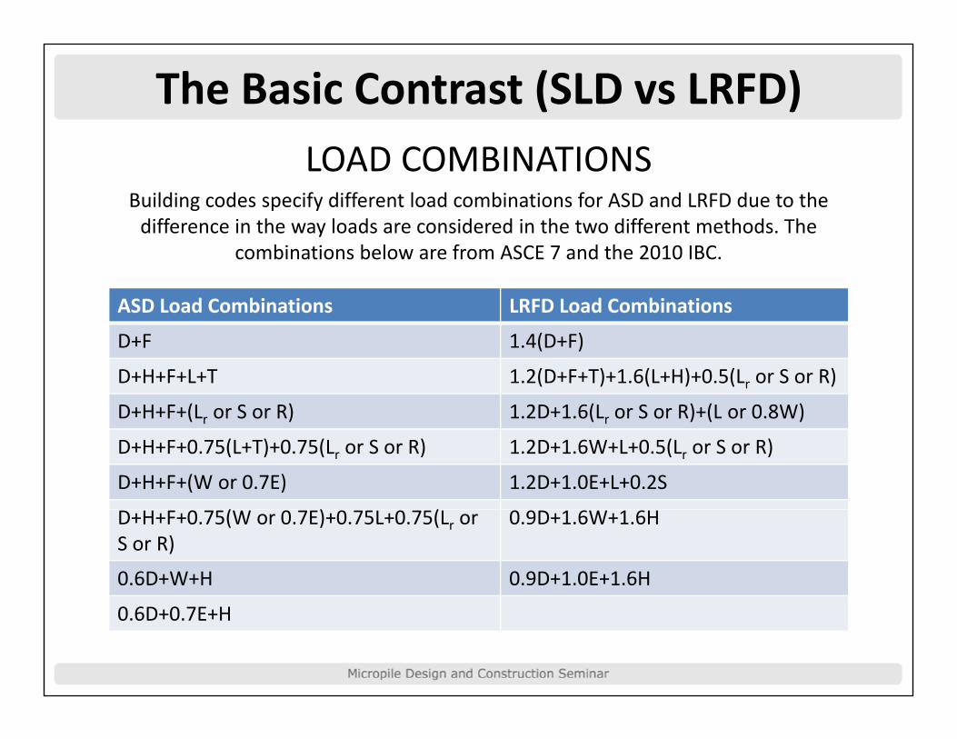
The Basic Contrast (SLD vs LRFD)LOAD COMBINATIONS
Building codes specify different load combinations for ASD and LRFD due to the difference in the way loads are considered in the two different methods Thedifference in the way loads are considered in the two different methods. The
combinations below are from ASCE 7 and the 2010 IBC.
ASD Load Combinations LRFD Load Combinations
D+F 1.4(D+F)
D+H+F+L+T 1.2(D+F+T)+1.6(L+H)+0.5(Lr or S or R)
D+H+F+(L or S or R) 1.2D+1.6(L or S or R)+(L or 0.8W)D+H+F+(Lr or S or R) 1.2D+1.6(Lr or S or R)+(L or 0.8W)
D+H+F+0.75(L+T)+0.75(Lr or S or R) 1.2D+1.6W+L+0.5(Lr or S or R)
D+H+F+(W or 0.7E) 1.2D+1.0E+L+0.2S
( ) (D+H+F+0.75(W or 0.7E)+0.75L+0.75(Lr or S or R)
0.9D+1.6W+1.6H
0.6D+W+H 0.9D+1.0E+1.6H
0.6D+0.7E+H

The Basic Contrast (SLD vs LRFD)It is difficult to directly compare SLD results and LRFD results because in LRFD, the factored loads
d i ti i d i tused in computing required resistance vary based on how much of different types of load are present because load factors are differentare present because load factors are different for different types of load. Otherwise, the
relationship between SLD and LRFD would berelationship between SLD and LRFD would be the simple relationship:
Load Factor / Resistance Factor = Factor of SafetySafety

Existing Micropile GuidelinesPublication Name Year of
PublicationDeveloping Entity
Design Method(s)
Drilled and Grouted Micropiles – State of P ti R i (4 V l )
1997 FHWA ASDPractice Review (4 Volumes)
Micropile Design and Construction Guidelines – Implementation Manual
1997 FHWA ASD & LFD
/Guide to Drafting a Specification for Micropiles
2004 DFI / ADSC ASD
Micropile Design and Construction Reference Manual
2005 FHWA / NHI ASDReference Manual
International Building Code – MicropileSection
2006 ICC ASD
AASHTO LRFD B id D i S ifi ti 2007 AASHTO LRFDAASHTO LRFD Bridge Design Specification – Micropile Section
2007 AASHTO LRFD
DFI / ADSC Micropile Specification Forthcoming DFI / ADSC ASD & LRFD
d d l d h /Updated Micropile Design and Construction Reference Manual
Forthcoming FHWA / NHI LRFD

Existing Micropile GuidelinesAs far as micropile‐specific codes and
requirements, the introduction of an LRFD based design requirement is relatively new. The AASHTO LRFD Bridge Design Specification didn’t adopt a micropile section until 2007.
Prior to that, all micropile design specifications were based on SLD / ASD. In fact, micropile design requirements included in the International Building Code are still
based on SLD / ASD.

ASD Methodologies for MicropilesIn terms of Working Stress or Allowable Stress Design methodologies for micropiles, there are t i difi d h th t htwo primary codified approaches that have substantially different allowable stresses for structural design of micropile cross sectionsstructural design of micropile cross sections.
FHWA A hFHWA ApproachMicropile Design and Construction Guidelines – Implementation Manual
Micropile Design and Construction ‐ Reference Manual
International Building Code ApproachDFI / ADSC Guide to Drafting a Specification fro Micropiles
International Building CodeInternational Building Code

ASD Methodologies for Micropilesl lMicropile Structural Capacity
• Compression Strength (Ultimate)Puc = 0.85fc’ Ag + Fy As
• Compression Strength (Allowable)Pac = A fc’ Ag + B Fy As
T i St th (Yi ld)• Tension Strength (Yield)Put = Fy As
• Tension Strength (Allowable)Pat = C Fy AsPat C Fy As
Where A, B and C are reduction factors which express the allowable stresses as a percentage of ultimate stress. The magnitude of these reduction factors varies depending on which design code you are using.
The core assumption with regard to the above compressive strength formulas is that the pile is sufficiently supported along its length by soil or rock such that buckling cannot occur. Most soils will provide a level of support that is sufficient to preclude outright buckling. However, the stiffness of the overburden soils can effect the actual pile capacity. This is not taken into account in the f lformulas.

ASD Methodologies for MicropilesMicropile Structural Capacity ‐ FHWA
• Compression Strength (Allowable)p g ( )• Pac = 0.40 fc’ Ag + 0.47 Fy As
• Tension Strength (Allowable)Tension Strength (Allowable)• Pat = 0.55 Fy Ab
• Maximum Test Load (Allowable)• Ptc = 0.68fc’ Ag + 0.8Fy As per FHWA‐SA‐97‐070
• Ptt = 0.8 Fy Ab for ASTM A615 material
• Ptt = 0.8 Fu Ab for ASTM A722 material

ASD Methodologies for MicropilesMicropile Structural Capacity ‐ IBC
• Compression Loadingp g• Pac = 0.33 fc’ Ag + 0.40 Fy As
• Tension LoadingTension Loading• Pat = 0.60 Fy Ab (same as PTI)
• Steel yield stress limited to 80 ksi.
• Steel reinforcement must carry at least 40% of the load.

ASD Methodologies for MicropilesMicropile Structural Capacity ‐ Comparison
• Compression Loadingp g• FHWA: Pac = 0.40 fc’ Ag + 0.47 Fy As
• IBC: P = 0.33 f ’ A + 0.40 F AIBC: Pac 0.33 fc Ag + 0.40 Fy As
• Tension Loading• FHWA: P = 0 55 F A• FHWA: Pat = 0.55 Fy Ab
• IBC: Pat = 0.60 Fy Ab

ASD Methodologies for MicropilesMicropile Geotechnical Capacity• For design purposes, micropiles are usually g p p p yassumed to transfer their load to the ground through grout‐to‐ground skin friction, without any contribution from end bearing (FHWA, 1997).
• This assumption results in a pile that is for the most part geotechnically equivalent in tension and compression.
• Suggested bond values can be found in the FHWA Manuals as well as in the PTI Recommendations for Prestressed Rock and Soil Anchors.

ASD Methodologies for MicropilesMicropile Geotechnical Capacity ‐ FHWA
•
• IBC Code does not offer specific guidance for bond values for geotechnical design of micropiles.

ASD Methodologies for MicropilesSummary of Typical Grout to Ground Bond Values for Preliminary Micropile Design
Soil / Rock Description Typical Range of Grout-to-Ground Nominal StrengthType A Type B Type C Type D
English (psi) SI (kPa) English (psi) SI (kPa) English (psi) SI (kPa) English (psi) SI (kPa)min max avg min max avg min max avg min max avg min max avg min max avg min max avg min max avg
Silt and Clay (some sand) 5.1 10.2 7.6 35 70 52.5 5.1 13.8 9.4 35 95 65 7.3 17.4 12.3 50 120 85 7.3 21.0 14.1 50 145 97.5soft, medium plasticSilt and Clay (some sand) 7.3 17.4 12.3 50 120 85 10.2 27.6 18.9 70 190 130 13.8 27.6 20.7 95 190 142.5 13.8 27.6 20.7 95 190 142.5stiff, dense to very denseSand (some silt) 10.2 21.0 15.6 70 145 107.5 10.2 27.6 18.9 70 190 130 13.8 27.6 20.7 95 190 142.5 13.8 34.8 24.3 95 240 167.5fine, loose-medium denseSand (some silt, gravel) 13.8 31.2 22.5 95 215 155 17.4 52.2 34.8 120 360 240 21.0 52.2 36.6 145 360 252.5 21.0 55.8 38.4 145 385 265fine-coarse, med-very dense, yGravel (some sand) 13.8 38.4 26.1 95 265 180 17.4 52.2 34.8 120 360 240 21.0 52.2 36.6 145 360 252.5 21.0 55.8 38.4 145 385 265medium-very denseGlacial Till (silt, sand, gravel) 13.8 27.6 20.7 95 190 142.5 13.8 45.0 29.4 95 310 202.5 17.4 45.0 31.2 120 310 215 17.4 48.6 33.0 120 335 227.5medium-very dense, cementedSoft Shales 29.7 79.8 54.8 205 550 377.5 -- -- -- -- -- -- -- -- -- -- -- -- -- -- -- -- -- --fresh-moderate fracturinglittle to no weatheringSlates and Hard Shales 74 7 200 2 137 4 515 1380 947 5 -- -- -- -- -- -- -- -- -- -- -- -- -- -- -- -- -- --Slates and Hard Shales 74.7 200.2 137.4 515 1380 947.5fresh-moderate fracturinglittle to no weatheringLimestone 150.1 300.2 225.2 1035 2070 1553 -- -- -- -- -- -- -- -- -- -- -- -- -- -- -- -- -- --fresh-moderate fracturinglittle to no weatheringSandstone 75.4 250.2 162.8 520 1725 1123 -- -- -- -- -- -- -- -- -- -- -- -- -- -- -- -- -- --fresh-moderate fracturinglittle to no weatheringlittle to no weatheringGranite and Basalt 200.2 609.2 404.7 1380 4200 2790 -- -- -- -- -- -- -- -- -- -- -- -- -- -- -- -- -- --fresh-moderate fracturinglittle to no weathering
Type A - Gravity grout only.
Type B - Pressure grouted through the casing during casing withdrawal.
Type C - Primary grout placed under gravity head, then one phase of secondary "global" pressure grouting.
Type D - Primary grout placed under gravity head, then one or more phases of secondary "global" pressure grouting.

AASHTO LRFD for Micropiles• First Edition of AASHTO LRFD
Bridge Specifications was published in 1994.
• It has undergone a gradual implementation program with an FHWA target date for full i l i b 2007implementation by 2007.
• Micropile Design Specification Section adopted in 2007 as a
t f S ti 10part of Section 10 –Foundations.
• Micropile ConstructionS ifi ti i tl dSpecification is currently under review for adoption and should be implemented in the near futurenear future.

AASHTO LRFD for Micropilesh d f l d• The design provisions for Micropiles under AASHTO LRFD Bridge Design Specifications are contained in Section 3 – Loads and Load Factorscontained in Section 3 Loads and Load Factors and in Section 10 – Foundations.
• Section 10 spells out the requirements for F d ti i l d f Mi ilFoundations in general and for Micropilesspecifically in various subsections of 10. It refers back to Section 3 for Loading related information. g
• We will review the major sections and subsections that are applicable to micropiles.
• In terms of any detailed discussion, we will focus on single micropiles under axial loading conditions only.conditions only.

AASHTO LRFD for MicropilesSection 10 Major Divisions
10 1 S10.1 – Scope10.2 – Definitions10 3 Notations10.3 – Notations
10.4 – Soil and Rock Properties10 5 – Limit States and Resistance Factors10.5 Limit States and Resistance Factors
10.6 – Spread Footings10.7 – Driven Piles0 e es10.8 – Drilled Shafts10.9 – Micropiles10.10 ‐ References

AASHTO LRFD for MicropilesSection 10.4 – Soil and Rock Properties (for
Foundations in general)
10 4 1 – Informational Needs10.4.1 Informational Needs
10.4.2 – Subsurface Exploration
10 4 3 L b T10.4.3 – Laboratory Tests
10.4.4 – In Situ Tests
10.4.5 – Geophysical Tests
10 4 6 – Selection of Design Properties10.4.6 Selection of Design Properties

AASHTO LRFD for MicropilesSection 10.5 – Limit States and Resistance
Factors (for Foundations in general)
10 5 1 – General10.5.1 General
10.5.2 – Service Limit States
10 5 3 S h Li i S10.5.3 – Strength Limit States
10.5.4 – Extreme Events Limit States
10.5.5 – Resistance Factors

AASHTO LRFD for MicropilesSection 10.5 – Limit States and Resistance
Factors
10 5 1 – General10.5.1 General
“F d i h ll b i d h h“Foundations shall be proportioned so that the factored resistance is not less than the effects of
h f d l d ifi d i S i 3 ”the factored loads specified in Section 3.”

AASHTO LRFD for Micropiles

AASHTO LRFD for Micropiles

AASHTO LRFD for MicropilesThe Load Combinations and Load Factors included in Table 3.4.1‐1 were developed
specifically for highway / bridge structures and may not be applicable to other structures.

AASHTO LRFD for MicropilesSection 10.5 – Limit States and Resistance Factors
10.5.2 – Service Limit States
Foundation design at the Service Limit State shall include:include:
• Settlements,
• Horizontal Movements• Horizontal Movements,
• Overall Stability,
• Scour at the Design Flood

AASHTO LRFD for MicropilesdSection 10.5 – Limit States and Resistance Factors
10.5.3 – Strength Limit States
10.5.3.1 – GeneralDesign of foundations at Strength Limit States shall include
id i f h i l h i l d l i fconsideration of the nominal geotechnical and structural resistances of the foundation elements. Design at strength limit states shall not
consider the deformations required to mobilize the nominal resistance, unless a definition of failure based on deformation is specified.p
The design of all foundations at the strength limit state shall consider:
• Structural Resistance and • Loss of lateral and vertical support due to scour at the design flood
event.

AASHTO LRFD for MicropilesdSection 10.5 – Limit States and Resistance Factors
10.5.3 – Strength Limit States
10.5.3.5 – MicropilesThe design of micropile foundations at the strength limit state shall
l idalso consider:• Axial compression resistance for single micropile,• Micropile group compression resistance,• Uplift resistance for single micropile,• Uplift resistance for micropile groups,• Micropile group punching failure into a weaker stratum below
th b i t t d i l i il hi f ilthe bearing stratum, and single micropile punching failure where tip resistance is considered,
• Single micropile and micropile group lateral resistance, and• Constructability including method(s) of micropile• Constructability, including method(s) of micropile
construction.

AASHTO LRFD for MicropilesdSection 10.5 – Limit States and Resistance Factors
10.5.5 – Resistance Factors
10.5.5.1 – Service Limit StatesResistance factors for the service limit states shall be taken as 1.0,
id d f ll bili i A i l 11 6 2 3 A iexcept as provided for overall stability in Article 11.6.2.3. A resistance factor of 1.0 shall be used to assess the ability of the foundation to meet the specified deflection criteria after scour due to the design
flood.
10.5.5.2 – Strength Limit StatesResistance factors for different types of foundation systems at theResistance factors for different types of foundation systems at the strength limit state shall be taken as specified in Articles 10.5.5.2.2, 10.5.5.2.3, 10.5.5.2.4, and 10.5.5.2.5, unless regionally specific values or substantial successful experience is available to justify higher values.

AASHTO LRFD for MicropilesdSection 10.5 – Limit States and Resistance Factors
10.5.5 – Resistance Factors
10.5.5.2.5 – MicropilesResistance factors shall be selected from Table 10.5.5.2.5‐1 based on h h d d f d i i h i l i l il i Ifthe method used for determining the nominal axial pile resistance. If the resistance factors provided in Table 10.5.5.2.5‐1 are to be applied to piles in potentially creeping soils, highly plastic soils, weak rock, or other marginal ground type, the resistance factor values in the Table g g yp ,should be reduced by 20 percent to reflect greater design uncertainty.
The resistance factors in Table 10.5.5.2.5‐1 were calibrated by fitting to ASD procedures tempered with engineering judgment. The resistance p p g g j gfactors in Table 10.5.5.2.5.‐2 for structural resistance were calibrated
by fitting to ASD procedures and are equal to or slightly more conservative than corresponding resistance factors from Section 5 of
the AASHTO LRFD Specifications for reinforced concrete column designthe AASHTO LRFD Specifications for reinforced concrete column design.

AASHTO LRFD for Micropiles

AASHTO LRFD for Micropiles

AASHTO LRFD for MicropilesSection 10.5 – Limit States and Resistance Factors
10.5.5 – Resistance Factors
10.5.5.3 – Extreme Event Limit States
Resistance factors for extreme limit state includingResistance factors for extreme limit state, including
the design of foundations to resist earthquake, ice,
vehicle or vessel impact loads, shall be taken as 1.0. For uplift resistance of piles and shafts, the i t f t h ll b t k 0 80 lresistance factor shall be taken as 0.80 or less.

AASHTO LRFD for MicropilesSection 10 Major Divisions
10.6 – Spread Footings
10 7 Driven Piles10.7 – Driven Piles
10.8 – Drilled Shafts
10.9 – Micropiles
10.10 ‐ References

AASHTO LRFD for MicropilesSection 10.9 – Micropiles
10.9.1 – General
10 9 2 Service Limit State Design10.9.2 – Service Limit State Design
10.9.3 – Strength Limit State Design
10.9.4 – Extreme Event Limit State Design
10.9.5 – Corrosion and Deterioration
AASHTO LRFD for Micropiles
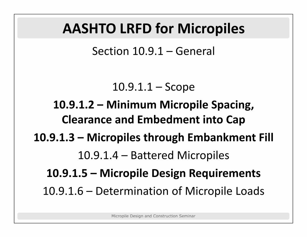
AASHTO LRFD for MicropilesSection 10.9.1 – General
10.9.1.1 – Scope
10 9 1 2 MinimumMicropile Spacing10.9.1.2 – Minimum Micropile Spacing, Clearance and Embedment into Cap
10 9 1 3 Mi il h h E b k Fill10.9.1.3 – Micropiles through Embankment Fill
10.9.1.4 – Battered Micropiles
10.9.1.5 – Micropile Design Requirements
10 9 1 6 – Determination of Micropile Loads10.9.1.6 Determination of Micropile Loads

AASHTO LRFD for MicropilesSection 10.9.1 – General
10.9.1.2 – Minimum Micropile Spacing, Clearance and Embedment into CapClearance and Embedment into Cap
C il i h ld b lCenter‐to‐center pile spacing should not be less than 30.0 in. or 3.0 pile diameters, whichever is
O h i h i i f A i lgreater. Otherwise, the provisions of Article 10.7.1.2 shall apply.

AASHTO LRFD for MicropilesSection 10.9.1 – General
10.9.1.3 – Micropiles through Embankment Fill
Micropiles extending through embankments h ll i i f 10 0 f ishall penetrate a minimum of 10.0 ft into
original ground, unless the required nominal i l d l l i laxial and lateral resistance occurs at a lesser
penetration below the embankment within b d k h i bl i lbedrock or other suitable support materials.

AASHTO LRFD for MicropilesS i 0 9 G lSection 10.9.1 – General
10.9.1.5 – Micropile Design Requirements
Micropile design shall address the following issues as appropriate:
• Nominal axial resistance to be specified in the contract and size of micropile group required to provide adequate support with consideration of how nominal axialrequired to provide adequate support, with consideration of how nominal axial micropile resistance will be determined in the field;
• Group interaction;• Pile quantity estimation from estimated pile penetration required to meet nominal
axial resistance and other design requirements;axial resistance and other design requirements;• Minimum pile penetration necessary to satisfy the requirements caused by uplift,
scour, downdrag, settlement, liquefaction, lateral loads, and seismic conditions;• Foundation deflection to meet the established movement and associated structure
performance criteria;performance criteria;• Pile foundation nominal structural resistance; and• Long‐term durability of the micropile in service, i.e. corrosion and deterioration.

AASHTO LRFD for MicropilesSection 10.9.2 – Service Limit State Design
10.9.2.1 – General
10 9 2 2 Tolerable Movements10.9.2.2 – Tolerable Movements
10.9.2.3 – Settlement
10.9.2.4 – Horizontal Micropile Foundation Movement
10.9.2.5 – Settlement Due to Downdrag
10 9 2 6 – Lateral Squeeze10.9.2.6 Lateral Squeeze

AASHTO LRFD for MicropileshSection 10.9.3 – Strength Limit State Design
10.9.3.1 – General10.9.3.2 – Ground Water and Bouyancy
10.9.3.3 – Scour10 9 3 4 D d10.9.3.4 – Downdrag
10.9.3.5 ‐ Nominal Axial Compression Resistance of a Single Micropile
10.9.3.6 – Resistance of Micropile Groups in Compression10.9.3.7 – Nominal Uplift Resistance of a Single Micropile10.9.3.8 – Nominal Uplift Resistance of Micropile Groups10.9.3.8 Nominal Uplift Resistance of Micropile Groups10.9.3.9 – Nominal Horizontal Resistance of Micropiles and
Micropile Groups10 9 3 10 Structural Resistance10.9.3.10 – Structural Resistance

AASHTO LRFD for MicropileshSection 10.9.3 – Strength Limit State Design
10.9.3.1 – GeneralFor strength limit state design, the following shall
be determined:• Loads and performance requirements;• Micropile dimensions and nominal axial micropile resistance;• Size and configuration of the micropile group to provide adequate
foundation support;• Estimated micropile length to be used in the construction contract
documents to provide a basis for bidding;• A minimum micropile penetration, if required, for the particular site
conditions and loading determined based on the maximumconditions and loading, determined based on the maximum (deepest) penetration needed to meet all of the applicable requirements identified in Article 10.7.6; and
• The nominal structural resistance of the micropile and/or micropilep / pgroup.

AASHTO LRFD for MicropilesSection 10.9.3 – Strength Limit State Design
10.9.3.5 – Nominal Axial Compression Resistance of a Single MicropileResistance of a Single Micropile
Mi il h ll b d i d i f il fMicropiles shall be designed to resist failure of the bonded length in soil and rock, or for
i il b i k f il f h kmicropiles bearing on rock, failure of the rock at the micropile tip.

AASHTO LRFD for MicropilesSection 10.9.3.5 – Nominal Axial Compression
Resistance of a Single Micropile
The factored resistance of a micropile, RR, shall be taken as:

AASHTO LRFD for MicropilesSection 10.9.3.5 – Nominal Axial Compression
Resistance of a Single Micropile

AASHTO LRFD for Micropiles

AASHTO LRFD for MicropileshSection 10.9.3 – Strength Limit State Design
10.9.3.5 – Nominal Axial Compression Resistance of a Single p gMicropile
10 9 3 5 4 – Micropile Load Test10.9.3.5.4 – Micropile Load Test
The load test shall follow the procedures specified in ASTM D1143 f i d ASTM D3689 f t i ThD1143 for compression and ASTM D3689 for tension. The
loading procedure should follow the Quick Load Test Method, unless detailed longer‐term load settlement data is needed, in which case the standard loading procedure should be usedwhich case the standard loading procedure should be used. Unless specified otherwise by the Engineer, the pile axial resistance shall be determined from the test data using the
Davisson Method as presented in Article 10 7 3 8 2Davisson Method as presented in Article 10.7.3.8.2.

AASHTO LRFD for MicropileshSection 10.9.3 – Strength Limit State Design
10.9.3.5 – Nominal Axial Compression Resistance of a Single Micropile
10.9.3.5.4 – Micropile Load Test
The number of load tests required to account for site variability shall be as specified in Article 10.5.5.2.2. The number of test micropilesrequired should be increased in nonuniform subsurface conditions.
In addition, proof tests loaded to the required factored load shall be performed on one pile per substructure unit or five percent of the
piles, whichever is greater, unless specified otherwise by thepiles, whichever is greater, unless specified otherwise by the Engineer.
The resistance factors for axial compressive resistance or axial uplift p presistance shall be taken as specified in Table 10.5.5.2.5‐1.

AASHTO LRFD for MicropilesSection 10.9.3 – Strength Limit State Design
10.9.3.7 – Nominal Uplift Resistance of a Single Micropile
Uplift resistance shall be evaluated when pupward loads act on the micropiles. Micropilessubjected to uplift forces shall be investigated for resistance to pullout, for their structural
strength, and for the strength of their ti t t d tconnection to supported components.

AASHTO LRFD for MicropileshSection 10.9.3 – Strength Limit State Design
10 9 3 10 St t l R i t10.9.3.10 – Structural Resistance
10 9 3 10 2 Axial Compressive Resistance10.9.3.10.2 ‐ Axial Compressive Resistance10.9.3.10.2a ‐ Cased Length
10 9 3 10 2b ‐ Uncased Length10.9.3.10.2b Uncased Length10.9.3.10.3 ‐ Axial Tension Resistance
10.9.3.10.3a ‐ Cased Length0 9 3 0 3a ased e gt10.9.3.10.3b ‐ Uncased Length
10.9.3.10.4 ‐ Plunge Length Transfer Load

AASHTO LRFD for Micropiles10.9.3.10.2 ‐ Axial Compressive Resistance

AASHTO LRFD for Micropiles10.9.3.10.2 ‐ Axial Compressive Resistance
10.9.3.10.2a ‐ Cased Lengthg

AASHTO LRFD for Micropiles

AASHTO LRFD for Micropiles10.9.3.10.2 ‐ Axial Compressive Resistance
10.9.3.10.2b ‐ Uncased Lengthg

AASHTO LRFD for Micropiles10.9.3.10.3 ‐ Axial Tension Resistance

AASHTO LRFD for Micropiles10.9.3.10.3 ‐ Axial Tension Resistance
10.9.3.10.3a ‐ Cased Lengthg

AASHTO LRFD for Micropiles10.9.3.10.3 ‐ Axial Tension Resistance
10.9.3.10.3b ‐ Uncased Lengthg

AASHTO LRFD for Micropiles10.9.3.10.4 – Plunge Length Transfer Load
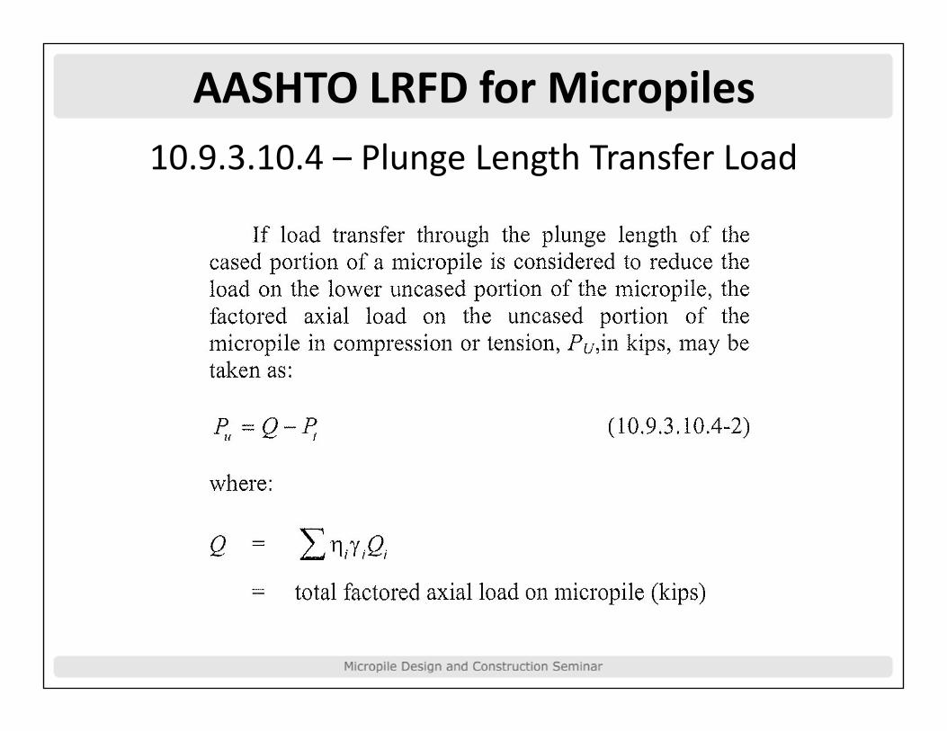
AASHTO LRFD for Micropiles10.9.3.10.4 – Plunge Length Transfer Load

Limitations of AASHTO LRFDd b d d ( bl• Load Combinations and Load Factors in Section 3 (Table
3.4.1‐1) were developed specifically for bridges and may not be applicable to other structures.
• Current Resistance Factors are calibrated based on fitting to ASD, not on reliability theory. Therefore does not truly reflect reliability based design at this time except in format.
• No Strength Limit State Checks for lateral loads. Not enough consensus exists in terms of design methodology for LRFD.
• Includes strain compatibility related stress limitations which have been shown to be erroneous for reinforcing in a confined condition.
• Davisson is the criteria for determining the Resistance of a micropile. Davisson is generally considered to be overly conservative and inappropriate for micropiles.

Design Example and Comparison
For comparison of the different design p gapproaches; we will look at one example
micropile configuration and analyze it with two p g yASD methodologies (FHWA and IBC) and
AASHTO LRFD for comparison. p
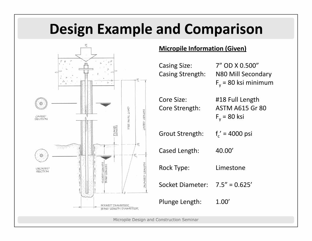
Design Example and ComparisonMicropile Information (Given)
Casing Size: 7” OD X 0.500”Casing Strength: N80 Mill SecondaryCasing Strength: N80 Mill Secondary
Fy = 80 ksi minimum
Core Size: #18 Full LengthCore Strength: ASTM A615 Gr 80
Fy = 80 ksi
Grout Strength: fc’ = 4000 psiGrout Strength: fc 4000 psi
Cased Length: 40.00’
R k T Li tRock Type: Limestone
Socket Diameter: 7.5” = 0.625’
Plunge Length: 1.00’

Design Example and ComparisonBasic Cross Section Properties#18 Bar Core, 7”OD X 0.500” Casing, 7 5” S k t Di t7.5” Socket Diameter
CASED SECTIONCASED SECTION
Abar = 4.00 in2 (#18)
Acasing = 3.1416(ro2‐ri2) = 10.21 in2casing ( o i )
Agrout = 3.1416(3)2‐4.00 = 24.27 in2
UNCASED SECTION
Abar = 4.00 in2 (#18)
A 3 1416(3 75)2 4 00 40 18 i 2Agrout = 3.1416(3.75)2‐4.00 = 40.18 in2

Design Example and ComparisonCompression Structural Design– Cased Length

Design Example and ComparisonCompression Structural Design ‐ Uncased Length

Design Example and ComparisonTension Structural Design

Design Example and ComparisonTension Structural Design

Design Example and ComparisonStructural Design – Comparison
Compression Casep
FHWA ASD
P = 0 40 f ’ A + 0 47 f APac = 0.40 fc Ag + 0.47 fy As
IBC ASD
Pac = 0.33 fc’ Ag + 0.40 fy As
AASHTO LRFD EQUIVALENT ASD FORMULAQ
Pac = 0.36 fc’ Ag + 0.425 fy As (LFavg = 1.5)
P = 0 38 f ’ A + 0 45 f A (LF = 1 42)Pac = 0.38 fc Ag + 0.45 fy As (LFavg = 1.42)

Design Example and ComparisonStructural Design – Comparison
Tension Case
FHWA ASD
P = 0 55 f APat = 0.55 fy Ab
IBC ASD
Pat = 0.60 fy Ab
AASHTO LRFD EQUIVALENT ASD FORMULAQ
Pat = 0.533 fy Ab (LFavg = 1.5)
P = 0 563 f A (LF = 1 42)Pat = 0.563 fy Ab (LFavg = 1.42)

Design Example and ComparisonStructural Design ‐ Comparison
Compression Allowable Service Load – Cased
Compression Allowable Service Load – Uncased
Tension Allowable Service Load
Length Length
FHWA ASD 573 k 215 k 176 k
IBC ASD 487 k 181 k 192 k
AASHTO LRFD (LFavg=1.50)
518 k 194 k 171 k
AASHTO LRFD 547 k 205 k 180 k(LFavg=1.42)

Design Example and ComparisonStructural Design ‐ ComparisonCompression Allowable Service Load Cased Length
560
580
520
540
ad (k
ips)
480
500
Axial Loa
440
460
FHWA ASD IBC ASD AASHTO LRFD (LF = 1.50) AASHTO LRFD (LF = 1.42)

Design Example and ComparisonStructural Design ‐ ComparisonCompression Allowable Service Load Uncased Length
210
220
190
200
ad (k
ips)
180
190
Axial Loa
160
170
FHWA ASD IBC ASD AASHTO LRFD (LF = 1.50) AASHTO LRFD (LF = 1.42)

Design Example and ComparisonStructural Design ‐ Comparison
Tension Allowable Service Load
190
195
180
185
ad (k
ips)
170
175
Axial Loa
160
165
FHWA ASD IBC ASD AASHTO LRFD (LF = 1.50) AASHTO LRFD (LF = 1.42)

Design Example and ComparisonGeotechnical Design

Design Example and ComparisonGeotechnical Design

Design Example and ComparisonGeotechnical Design

Design Example and ComparisonGeotechnical Design

Design Example and ComparisonGeotechnical Design ‐ Comparison

Design Example and ComparisonGeotechnical Design ‐ Comparison
Geotechnical Allowable Service Load in Compression
230
240
210
220
ad (k
ips)
200
210
Axial Loa
180
190
FHWA ASD IBC ASD AASHTO LRFD (LF = 1.50) AASHTO LRFD (LF = 1.42)

Design Example and ComparisonOverall Pile Capacity ‐ Comparison
Compression Allowable Service Load
Tension Allowable Service
Required Socket Length
Load
FHWA ASD 236 k 176 k 11.14 feet
IBC ASD 202 k 192 k 10.05 feet
AASHTO LRFD (LFavg=1.50) 214 k 171 k 10.79 feet
AASHTO LRFD (LFavg=1.42) 226 k 180 k 10.79 feet
FHWA appears to be the most economical for compression loads. IBC appears to be the most economical for tension loads. AASHTO LRFD appears to be generally in the middle between the two except in the case of tension.
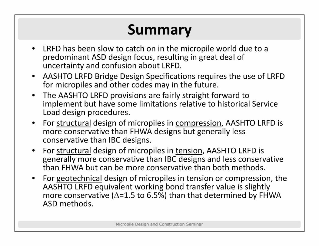
Summaryh b l h h l ld d• LRFD has been slow to catch on in the micropile world due to a
predominant ASD design focus, resulting in great deal of uncertainty and confusion about LRFD.
• AASHTO LRFD Bridge Design Specifications requires the use of LRFD• AASHTO LRFD Bridge Design Specifications requires the use of LRFD for micropiles and other codes may in the future.
• The AASHTO LRFD provisions are fairly straight forward to implement but have some limitations relative to historical Service pLoad design procedures.
• For structural design of micropiles in compression, AASHTO LRFD is more conservative than FHWA designs but generally less conservative than IBC designsconservative than IBC designs.
• For structural design of micropiles in tension, AASHTO LRFD is generally more conservative than IBC designs and less conservative than FHWA but can be more conservative than both methods.than FHWA but can be more conservative than both methods.
• For geotechnical design of micropiles in tension or compression, the AASHTO LRFD equivalent working bond transfer value is slightly more conservative (Δ=1.5 to 6.5%) than that determined by FHWA
h dASD methods.

THANK YOU!for Your Time and Attention
You will be rewarded accordingly…
Sho ld o ha e f rther q estion onta t me atShould you have further question, contact me at:

Visit www.micropile.org for current information on what's happening with micropile design and construction.