ls xlpe & accessories
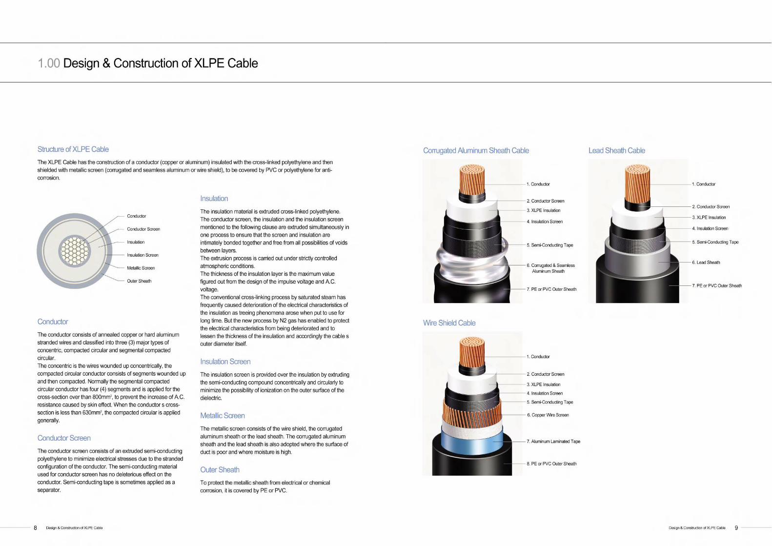
DESCRIPTION
XLPE & AccessoriesTRANSCRIPT

New Dream, New Start
To become a leader in the competitive global market, LG has been dividedinto three groups, electronics and chemicals for LG, energy and distribution for GS, Industrial electric·electronics and material for LSbased on their business specialties.
LS' main companies, such as LS cable, LS industrial systems, LS-Nikkocopper, Gaon cable, E1 and Yesco, are ranked as No.1 in theirrespective industry. However, LS won't just sit back, satisfied with beingthe best in Korea. We will pave the way for becoming the world's best inindustrial electric·electronics and material industry with the new CI, LS.
Your good partner LG Cable is making afresh start as LS Cable
LS Cable is No. 1 cable maker in Korea and its business fields aretelecommunication, electric power, components & materials andmachinery. Also, LS Cable is creating new businesses particularly incomponent and materials industry. LS Cable makes its best to accomplishthe vision, 'Your No.1 Creative Partner' and be one of the world leaderswith high technology and best level of service.
Leading SolutionLG Cable, LG Industrial Systems and LG-Nikko Copper,
Gaon Cable, E1 and Yesco are starting with
a new name, Leading Solution, LS.


C o r r u g a t e dAl Sheath
W i r eS h i e l d
L e a dS h e a t h
S t r a n d i n g
S e g m e n tS t r a n d i n g
T a p i n g
I n s u l a t i o n
D e g a s s i n g
C o m p a c tC i r c u l a r
S e g m e n t a lC o m p a c t
T a p i n g
O u t e rS h e a t h
T e s t i n g
S h i p p i n g
Extrusion The conductor screen, the insulation and the insulationscreen are simultaneously extruded with thecompounds supplied from the clean room.
Manufacturing Process & VCV Line 1 1
2 . 0 0 Manufacturing Process & VCV Line
Manufacturing Process & VCV Line1 0
The system adopted for insulation of the XLPE Cable is VCV and N2 gas is used for cross linking, and the line is extruded in a vertical type.The outstanding characteristics of the XLPE Cable manufactured in application of this system are :
1. The insulation has no eccentricity. 2. The cross-linking by use of N2 gas guarantees excellent electrical characteristics of the insulation. 3. The simultaneous extrusion of the inner and outer semi-conducting layers and the insulation prevents treeing and other irregularities. 4. Uniformity of quality is maintained of all products as the manufacturing processes are controlled by computer.
C o n d u c t o r
Semi Conducting Tape
Semi Conducting Tape
C o m p o u n d
Cross-Linking and Cooling The corss-linking takes place in curing zone of A bycirculating N2 gas and the insulation is formed into corethrough precooling zone of B and cooling zone of C.
A
Pay Off The conductor wound uparound the drum is set atpay off to run to meteringc a p s t a n .Take Up
The cable comes to be wound up again around thedrum to go into the next process.
B
C
D r a w i n g

4.00 XLPE Insulated Cables
4 . 0 1 36/66 (72.5) kV with Aluminum Sheath
4.02 36/66 (72.5) kV with Lead Sheath
4.03 36/66 (72.5) kV with Copper Wire Shield
4.04 64/110 (123) kV with Aluminum Sheath
4.05 64/110 (123) kV with Lead Sheath
4.06 64/110 (123) kV with Copper Wire Shield
4.07 76/132 (145) kV with Aluminum Sheath
4.08 76/132 (145) kV with Lead Sheath
4.09 76/132 (145) kV with Copper Wire Shield
4.10 87/161 (170) kV with Aluminum Sheath
4.11 87/161 (170) kV with Lead Sheath
4.12 87/161 (170) kV with Copper Wire Shield
4.13 127/230 (245) kV with Aluminum Sheath
4.14 127/230 (245) kV with Lead Sheath
4.15 127/230 (245) kV with Copper Wire Shield
4.16 190/345 (362) kV with Aluminum Sheath
4.17 190/345 (362) kV with Lead Sheath
4.18 220/400 (420) kV with Aluminum Sheath
4.19 220/400 (420) kV with Lead Sheath
3 . 0 0 Cable Construction & Continuous Current Ratings
The continuous current capacity is calculated in accordance with IEC 60287.
Laying Conditions
1) Ground Temperature : 25
2) Depth of Laying : 1.5m
3) Soil Thermal Resistivity : 1.0m / W
4) Ambient Temperature : 40
5) Max. Conductor Temperature : 90
6) Cable Formation : Flat (S=2D) S : Distance between cables / D : Cable diameter
7) Frequency : 50Hz
8) Load factor : 100%
Maximum Permissible Conductor Te m p e r a t u r e
1 ) Normal OperationNormal operation is meant to be maintained through out a given period of time everydayor continuously, without affecting the operation.
2) Emergency LoadEmergency load is meant to be maintained for a short time under the condition ofsystem breakdown or under the state of excessively loaded operation, without causinga defect.
3) Short Circuit Short circuit is meant to cause no defect of the cable when an irregular current, flows forshort time due to shorting or earthing.
Cable Construction & Continuous Current Ratings1 2
Normal Operation Emergency Operation
9 0 1 3 0 2 5 0
Short Circuit

4 . 0 2 36/66 (72.5) kV with Lead Sheath
Construction Copper Conductor / XLPE Insulation / Lead Sheath / PE (or PVC) Outer Sheath
Continuous Current Ratings for Single Circuit (A)
Constructional Data (Nominal Va l u e s )
C o n d u c t o r
Thickness of Conductor Screen Approx.mm
Thickness of Insulation (mm)
Thickness of Insulation Screen Approx.mm
Thickness of Lead Sheath (mm)
Thickness of Outer Sheath (mm)
Outer Diameter of Cable (mm)
Weight of Cable (kg /m )
Max. DC Conductor Resistance at 20 (Ω/k m )
Capacitance (/k m )
Cross-Sectional Area (mm2)
Diameter (mm)
S h a p e
2 4 0
1 8 . 1
1 . 0
1 1 . 0
1 . 0
2 . 1
3 . 5
6 2
8 . 1
0 . 0 7 5 4
0 . 2 0
3 0 0
2 0 . 4
1 . 0
1 1 . 0
1 . 0
2 . 2
3 . 5
6 4
9 . 1
0 . 0 6 0 1
0 . 2 1
4 0 0
2 3 . 2
1 . 0
1 1 . 0
1 . 0
2 . 3
3 . 5
6 7
1 0 . 5
0 . 0 4 7 0
0 . 2 3
5 0 0
2 6 . 3
1 . 0
1 1 . 0
1 . 0
2 . 4
4 . 0
7 2
1 2 . 5
0 . 0 3 6 6
0 . 2 5
6 3 0
3 0 . 2
1 . 0
1 1 . 0
1 . 0
2 . 4
4 . 0
7 6
1 4 . 2
0 . 0 2 8 3
0 . 2 8
8 0 0
3 4 . 0
1 . 0
1 1 . 0
1 . 0
2 . 6
4 . 0
8 0
1 6 . 9
0 . 0 2 2 1
0 . 3 0
1 0 0 0
3 8 . 7
1 . 0
1 1 . 0
1 . 0
2 . 7
4 . 0
8 5
1 9 . 9
0 . 0 1 7 6
0 . 3 3
1 2 0 0
4 1 . 8
1 . 0
1 1 . 0
1 . 0
2 . 8
4 . 5
9 1
2 3 . 0
0 . 0 1 5 1
0 . 3 6
1 6 0 0
4 8 . 1
1 . 0
1 1 . 0
1 . 0
3 . 0
4 . 5
9 7
2 8 . 0
0 . 0 1 1 3
0 . 4 0
2 0 0 0
5 4 . 3
1 . 0
1 1 . 0
1 . 0
3 . 2
4 . 5
1 0 4
3 3 . 4
0 . 0 0 9 0
0 . 4 4
Compact Round Stranded Segment Stranded (Miliken)
XLPE Insulated Cables 1 5
2 4 0
5 3 5
5 0 2
6 2 1
7 0 6
3 0 0
6 0 6
5 6 7
7 1 0
8 1 0
4 0 0
6 9 1
6 4 6
8 2 2
9 4 2
5 0 0
7 8 7
7 3 3
9 5 1
1 0 9 8
6 3 0
8 9 8
8 3 3
1 0 9 6
1 2 7 4
8 0 0
1 0 0 8
9 5 8
1 2 4 3
1 4 6 2
1 0 0 0
1 1 8 4
1 1 2 1
1 5 0 5
1 7 5 9
1 2 0 0
1 2 8 2
1 2 0 8
1 6 4 8
1 9 3 8
1 6 0 0
1 4 6 9
1 4 3 4
1 9 0 6
2 2 8 2
2 0 0 0
1 6 2 6
1 5 8 5
2 1 3 0
2 5 9 7
Cross-Sectional Area (mm2)
Direct Buried
Pipe Duct
T r e f o i l
Flat (S=2D)In Air
4 . 0 1 36/66 (72.5) kV with Aluminum Sheath
Construction Copper Conductor / XLPE Insulation / Aluminum Sheath / PE (or PVC) Outer Sheath
Continuous Current Ratings for Single Circuit (A)
XLPE Insulated Cables1 4
Constructional Data (Nominal Va l u e s )
C o n d u c t o r
Thickness of Conductor Screen Approx.mm
Thickness of Insulation (mm)
Thickness of Insulation Screen Approx.mm
Thickness of Aluminum Sheath (mm)
Thickness of Outer Sheath (mm)
Outer Diameter of Cable (mm)
Weight of Cable (kg /m )
Max. DC Conductor Resistance at 20 (Ω/k m )
Capacitance (/k m )
Cross-Sectional Area (mm2)
Diameter (mm)
S h a p e
2 4 0
1 8 . 1
1 . 0
1 1 . 0
1 . 0
1 . 6
3 . 5
6 9
5 . 5
0 . 0 7 5 4
0 . 2 0
3 0 0
2 0 . 4
1 . 0
1 1 . 0
1 . 0
1 . 6
3 . 5
7 2
6 . 3
0 . 0 6 0 1
0 . 2 1
4 0 0
2 3 . 2
1 . 0
1 1 . 0
1 . 0
1 . 7
3 . 5
7 5
7 . 2
0 . 0 4 7 0
0 . 2 3
5 0 0
2 6 . 3
1 . 0
1 1 . 0
1 . 0
1 . 8
4 . 0
7 9
8 . 6
0 . 0 3 6 6
0 . 2 5
6 3 0
3 0 . 2
1 . 0
1 1 . 0
1 . 0
1 . 8
4 . 0
8 3
1 0 . 1
0 . 0 2 8 3
0 . 2 8
8 0 0
3 4 . 0
1 . 0
1 1 . 0
1 . 0
1 . 9
4 . 0
8 7
1 2 . 0
0 . 0 2 2 1
0 . 3 0
1 0 0 0
3 8 . 7
1 . 0
1 1 . 0
1 . 0
2 . 0
4 . 0
9 2
1 4 . 4
0 . 0 1 7 6
0 . 3 3
1 2 0 0
4 1 . 8
1 . 0
1 1 . 0
1 . 0
2 . 1
4 . 5
9 8
1 6 . 7
0 . 0 1 5 1
0 . 3 6
1 6 0 0
4 8 . 1
1 . 0
1 1 . 0
1 . 0
2 . 2
4 . 5
1 0 5
2 0 . 9
0 . 0 1 1 3
0 . 4 0
Compact Round Stranded Segment Stranded (Miliken)
Cross-Sectional Area (mm2)
Direct Buried
Pipe Duct
T r e f o i l
Flat (S=2D)In Air
2 4 0
5 2 4
4 9 1
5 9 8
6 7 1
3 0 0
5 9 2
5 5 6
6 8 2
7 7 0
4 0 0
6 7 1
6 3 1
7 8 1
8 8 8
5 0 0
7 6 2
7 1 4
8 9 4
1 0 2 5
6 3 0
8 7 8
8 0 8
1 0 2 3
1 1 8 7
8 0 0
9 6 5
9 2 8
1 1 5 0
1 3 5 5
1 0 0 0
1 1 1 9
1 0 7 5
1 3 6 1
1 6 1 5
1 2 0 0
1 1 9 8
1 1 4 6
1 4 6 0
1 7 4 5
1 6 0 0
1 3 5 2
1 3 5 7
1 6 5 4
2 0 3 0
2 0 0 0
1 4 6 8
1 4 7 5
1 8 0 0
2 2 7 3
2 0 0 0
5 4 . 3
1 . 0
1 1 . 0
1 . 0
2 . 4
4 . 5
1 1 2
2 5 . 4
0 . 0 0 9 0
0 . 4 4

4 . 0 4 6 4 / 110 (123) kV with Aluminum Sheath
Construction Copper Conductor / XLPE Insulation / Aluminum Sheath / PE (or PVC) Outer Sheath
Continuous Current Ratings for Single Circuit (A)
Constructional Data (Nominal Va l u e s )
C o n d u c t o r
Thickness of Conductor Screen Approx.mm
Thickness of Insulation (mm)
Thickness of Insulation Screen Approx.mm
Thickness of Aluminum Sheath (mm)
Thickness of Outer Sheath (mm)
Outer Diameter of Cable (mm)
Weight of Cable (kg /m )
Max. DC Conductor Resistance at 20 (Ω/k m )
Capacitance (/k m )
Cross-Sectional Area (mm2)
Diameter (mm)
S h a p e
2 4 0
1 8 . 1
1 . 2
1 4 . 0
1 . 0
1 . 7
3 . 5
7 6
6 . 3
0 . 0 7 5 4
0 . 1 7
3 0 0
2 0 . 4
1 . 2
1 4 . 0
1 . 0
1 . 8
3 . 5
7 8
7 . 0
0 . 0 6 0 1
0 . 1 8
4 0 0
2 3 . 2
1 . 2
1 4 . 0
1 . 0
1 . 8
3 . 5
8 1
8 . 0
0 . 0 4 7 0
0 . 2 0
5 0 0
2 6 . 3
1 . 2
1 4 . 0
1 . 0
1 . 9
4 . 0
8 6
9 . 3
0 . 0 3 6 6
0 . 2 1
6 3 0
3 0 . 2
1 . 2
1 4 . 0
1 . 0
2 . 0
4 . 0
9 0
1 1 . 0
0 . 0 2 8 3
0 . 2 3
8 0 0
3 4 . 0
1 . 2
1 4 . 0
1 . 0
2 . 0
4 . 0
9 4
1 2 . 9
0 . 0 2 2 1
0 . 2 5
1 0 0 0
3 8 . 7
1 . 2
1 4 . 0
1 . 0
2 . 1
4 . 0
9 9
1 5 . 4
0 . 0 1 7 6
0 . 2 8
1 2 0 0
4 1 . 8
1 . 2
1 4 . 0
1 . 0
2 . 2
4 . 5
1 0 4
1 7 . 7
0 . 0 1 5 1
0 . 3 0
1 6 0 0
4 8 . 1
1 . 2
1 4 . 0
1 . 0
2 . 4
4 . 5
1 1 1
2 2 . 1
0 . 0 1 1 3
0 . 3 3
2 0 0 0
5 4 . 3
1 . 2
1 4 . 0
1 . 0
2 . 5
4 . 5
1 1 8
2 6 . 5
0 . 0 0 9 0
0 . 3 6
Compact Round Stranded Segment Stranded (Miliken)
XLPE Insulated Cables 1 7
2 4 0
5 2 0
4 9 1
5 9 2
6 5 7
3 0 0
5 8 7
5 5 0
6 7 7
7 5 5
4 0 0
6 6 7
6 3 9
7 7 5
8 7 3
5 0 0
7 5 8
7 2 5
8 8 9
1 0 0 6
6 3 0
8 6 0
8 2 1
1 0 2 0
1 1 6 9
8 0 0
9 6 1
9 1 5
1 1 4 7
1 3 3 3
1 0 0 0
1 1 0 9
1 0 5 7
1 3 4 6
1 5 8 1
1 2 0 0
1 1 8 7
1 1 8 0
1 4 5 1
1 7 1 7
1 6 0 0
1 3 3 8
1 3 3 2
1 6 3 5
1 9 9 5
2 0 0 0
1 4 5 8
1 4 4 7
1 7 8 7
2 2 3 6
Cross-Sectional Area (mm2)
Direct Buried
Pipe Duct
T r e f o i l
Flat (S=2D)In Air
4 . 0 3 36/66 (72.5) kV with Copper Wire Shield
Construction Copper Conductor / XLPE Insulation / Copper Wire Shield / PE (or PVC) Outer Sheath
Continuous Current Ratings for Single Circuit (A)
XLPE Insulated Cables1 6
Constructional Data (Nominal Va l u e s )
C o n d u c t o r
Thickness of Conductor Screen Approx.mm
Thickness of Insulation (mm)
Thickness of Insulation Screen Approx.mm
Diameter & Number of Copper Wires (mm x No.)
Thickness of Outer Sheath (mm)
Outer Diameter of Cable (mm)
Weight of Cable (kg /m )
Max. DC Conductor Resistance at 20 (Ω/k m )
Capacitance (/k m )
Cross-Sectional Area (mm2)
Diameter (mm)
S h a p e
2 4 0
1 8 . 1
1 . 0
1 1 . 0
1 . 0
1.2 x 40
3 . 5
5 8
4 . 4
0 . 0 7 5 4
0 . 2 0
3 0 0
2 0 . 4
1 . 0
1 1 . 0
1 . 0
1.2 x 40
3 . 5
6 0
5 . 1
0 . 0 6 0 1
0 . 2 1
4 0 0
2 3 . 2
1 . 0
1 1 . 0
1 . 0
1.2 x 40
3 . 5
6 3
5 . 9
0 . 0 4 7 0
0 . 2 3
5 0 0
2 6 . 3
1 . 0
1 1 . 0
1 . 0
1.2 x 40
4 . 0
6 6
7 . 2
0 . 0 3 6 6
0 . 2 5
6 3 0
3 0 . 2
1 . 0
1 1 . 0
1 . 0
1.2 x 40
4 . 0
7 1
8 . 6
0 . 0 2 8 3
0 . 2 8
8 0 0
3 4 . 0
1 . 0
1 1 . 0
1 . 0
1.2 x 40
4 . 0
7 5
1 0 . 4
0 . 0 2 2 1
0 . 3 0
1 0 0 0
3 8 . 7
1 . 0
1 1 . 0
1 . 0
1.2 x 40
4 . 0
8 0
1 2 . 7
0 . 0 1 7 6
0 . 3 3
1 2 0 0
4 1 . 8
1 . 0
1 1 . 0
1 . 0
1.2 x 40
4 . 5
8 5
1 4 . 7
0 . 0 1 5 1
0 . 3 6
1 6 0 0
4 8 . 1
1 . 0
1 1 . 0
1 . 0
1.2 x 40
4 . 5
9 1
1 8 . 7
0 . 0 1 1 3
0 . 4 0
2 0 0 0
5 4 . 3
1 . 0
1 1 . 0
1 . 0
1.2 x 40
4 . 5
9 7
2 2 . 7
0 . 0 0 9 0
0 . 4 4
Compact Round Stranded Segment Stranded (Miliken)
Cross-Sectional Area (mm2)
Direct Buried
Pipe Duct
T r e f o i l
Flat (S=2D)In Air
2 4 0
5 3 0
4 8 3
6 0 6
6 9 2
3 0 0
5 9 9
5 4 4
6 9 3
7 9 5
4 0 0
6 8 3
6 1 6
8 0 2
9 2 5
5 0 0
7 8 0
7 2 9
9 2 9
1 0 7 5
6 3 0
8 8 6
8 2 8
1 0 6 6
1 2 4 7
8 0 0
9 9 7
9 2 9
1 2 1 0
1 4 3 2
1 0 0 0
1 1 7 3
1 0 8 7
1 4 7 3
1 7 2 8
1 2 0 0
1 2 7 0
1 1 7 3
1 6 1 1
1 8 9 4
1 6 0 0
1 4 6 5
1 3 7 5
1 8 8 3
2 2 4 5
2 0 0 0
1 6 2 7
1 5 3 0
2 1 1 1
2 5 5 6

4 . 0 6 6 4 / 110 (123) kV with Copper Wire Shield
Construction Copper Conductor / XLPE Insulation / Copper Wire Shield / PE (or PVC) Outer Sheath
Continuous Current Ratings for Single Circuit (A)
Constructional Data (Nominal Va l u e s )
C o n d u c t o r
Thickness of Conductor Screen Approx.mm
Thickness of Insulation (mm)
Thickness of Insulation Screen Approx.mm
Diameter & Number of Copper Wires (mm x No.)
Thickness of Outer Sheath (mm)
Outer Diameter of Cable (mm)
Weight of Cable (kg /m )
Max. DC Conductor Resistance at 20 (Ω/k m )
Capacitance (/k m )
Cross-Sectional Area (mm2)
Diameter (mm)
S h a p e
2 4 0
1 8 . 1
1 . 2
1 4 . 0
1 . 0
1.2 x 40
3 . 5
6 4
5 . 0
0 . 0 7 5 4
0 . 1 7
3 0 0
2 0 . 4
1 . 2
1 4 . 0
1 . 0
1.2 x 40
3 . 5
6 6
5 . 7
0 . 0 6 0 1
0 . 1 8
4 0 0
2 3 . 2
1 . 2
1 4 . 0
1 . 0
1.2 x 40
3 . 5
6 9
6 . 6
0 . 0 4 7 0
0 . 2 0
5 0 0
2 6 . 3
1 . 2
1 4 . 0
1 . 0
1.2 x 40
4 . 0
7 3
7 . 9
0 . 0 3 6 6
0 . 2 1
6 3 0
3 0 . 2
1 . 2
1 4 . 0
1 . 0
1.2 x 40
4 . 0
7 7
9 . 4
0 . 0 2 8 3
0 . 2 3
8 0 0
3 4 . 0
1 . 2
1 4 . 0
1 . 0
1.2 x 40
4 . 0
8 1
1 1 . 2
0 . 0 2 2 1
0 . 2 5
1 0 0 0
3 8 . 7
1 . 2
1 4 . 0
1 . 0
1.2 x 40
4 . 0
8 6
1 3 . 6
0 . 0 1 7 6
0 . 2 8
1 2 0 0
4 1 . 8
1 . 2
1 4 . 0
1 . 0
1.2 x 40
4 . 5
9 1
1 5 . 6
0 . 0 1 5 1
0 . 3 0
1 6 0 0
4 8 . 1
1 . 2
1 4 . 0
1 . 0
1.2 x 40
4 . 5
9 7
1 9 . 6
0 . 0 1 1 3
0 . 3 3
2 0 0 0
5 4 . 3
1 . 2
1 4 . 0
1 . 0
1.2 x 40
4 . 5
1 0 3
2 3 . 7
0 . 0 0 9 0
0 . 3 6
Compact Round Stranded Segment Stranded (Miliken)
XLPE Insulated Cables 1 9
2 4 0
5 2 8
4 9 5
6 0 5
6 8 2
3 0 0
5 9 7
5 5 9
6 9 2
7 8 3
4 0 0
6 8 1
6 5 0
8 0 0
9 0 9
5 0 0
7 7 5
7 3 9
9 2 2
1 0 5 3
6 3 0
8 8 4
8 4 1
1 0 6 5
1 2 2 6
8 0 0
9 9 4
9 4 5
1 2 0 8
1 4 0 6
1 0 0 0
1 1 6 9
1 1 0 6
1 4 6 5
1 6 9 5
1 2 0 0
1 2 6 4
1 2 3 1
1 5 9 5
1 8 4 9
1 6 0 0
1 4 5 6
1 4 1 5
1 8 6 0
2 1 8 5
2 0 0 0
1 6 1 8
1 5 7 0
2 0 8 9
2 4 8 7
Cross-Sectional Area (mm2)
Direct Buried
Pipe Duct
T r e f o i l
Flat (S=2D)In Air
4 . 0 5 6 4 / 110 (123) kV with Lead Sheath
Construction Copper Conductor / XLPE Insulation / Lead Sheath / PE (or PVC) Outer Sheath
Continuous Current Ratings for Single Circuit (A)
XLPE Insulated Cables1 8
Constructional Data (Nominal Va l u e s )
C o n d u c t o r
Thickness of Conductor Screen Approx.mm
Thickness of Insulation (mm)
Thickness of Insulation Screen Approx.mm
Thickness of Lead Sheath (mm)
Thickness of Outer Sheath (mm)
Outer Diameter of Cable (mm)
Weight of Cable (kg /m )
Max. DC Conductor Resistance at 20 (Ω/k m )
Capacitance (/k m )
Cross-Sectional Area (mm2)
Diameter (mm)
S h a p e
2 4 0
1 8 . 1
1 . 2
1 4 . 0
1 . 0
2 . 3
3 . 5
6 8
9 . 6
0 . 0 7 5 4
0 . 1 7
3 0 0
2 0 . 4
1 . 2
1 4 . 0
1 . 0
2 . 4
3 . 5
7 1
1 0 . 9
0 . 0 6 0 1
0 . 1 8
4 0 0
2 3 . 2
1 . 2
1 4 . 0
1 . 0
2 . 5
3 . 5
7 4
1 2 . 3
0 . 0 4 7 0
0 . 2 0
5 0 0
2 6 . 3
1 . 2
1 4 . 0
1 . 0
2 . 5
4 . 0
7 8
1 3 . 8
0 . 0 3 6 6
0 . 2 1
6 3 0
3 0 . 2
1 . 2
1 4 . 0
1 . 0
2 . 6
4 . 0
8 2
1 6 . 0
0 . 0 2 8 3
0 . 2 3
8 0 0
3 4 . 0
1 . 2
1 4 . 0
1 . 0
2 . 7
4 . 0
8 6
1 8 . 5
0 . 0 2 2 1
0 . 2 5
1 0 0 0
3 8 . 7
1 . 2
1 4 . 0
1 . 0
2 . 9
4 . 0
9 2
2 1 . 9
0 . 0 1 7 6
0 . 2 8
1 2 0 0
4 1 . 8
1 . 2
1 4 . 0
1 . 0
3 . 0
4 . 5
9 7
2 4 . 7
0 . 0 1 5 1
0 . 3 0
1 6 0 0
4 8 . 1
1 . 2
1 4 . 0
1 . 0
3 . 2
4 . 5
1 0 3
3 0 . 1
0 . 0 1 1 3
0 . 3 3
2 0 0 0
5 4 . 3
1 . 2
1 4 . 0
1 . 0
3 . 4
4 . 5
1 1 0
3 5 . 7
0 . 0 0 9 0
0 . 3 6
Compact Round Stranded Segment Stranded (Miliken)
Cross-Sectional Area (mm2)
Direct Buried
Pipe Duct
T r e f o i l
Flat (S=2D)In Air
2 4 0
5 3 3
4 9 8
6 1 7
6 9 2
3 0 0
6 0 2
5 6 3
7 0 5
7 9 4
4 0 0
6 8 7
6 5 4
8 1 6
9 2 3
5 0 0
7 8 2
7 4 4
9 3 9
1 0 6 8
6 3 0
8 9 1
8 4 6
1 0 8 3
1 2 4 3
8 0 0
1 0 0 1
9 4 9
1 2 2 9
1 4 2 5
1 0 0 0
1 1 7 6
1 1 0 8
1 4 8 6
1 7 1 8
1 2 0 0
1 2 6 9
1 2 3 5
1 6 1 2
1 8 7 1
1 6 0 0
1 4 5 5
1 4 1 5
1 8 7 0
2 2 0 6
2 0 0 0
1 6 0 9
1 5 6 2
2 0 8 7
2 5 0 5

4 . 0 8 76/132 (145) kV with Lead Sheath
Construction Copper Conductor / XLPE Insulation / Lead Sheath / PE (or PVC) Outer Sheath
Continuous Current Ratings for Single Circuit (A)
Constructional Data (Nominal Va l u e s )
C o n d u c t o r
Thickness of Conductor Screen Approx.mm
Thickness of Insulation (mm)
Thickness of Insulation Screen Approx.mm
Thickness of Lead Sheath (mm)
Thickness of Outer Sheath (mm)
Outer Diameter of Cable (mm)
Weight of Cable (kg /m )
Max. DC Conductor Resistance at 20 (Ω/k m )
Capacitance (/k m )
Cross-Sectional Area (mm2)
Diameter (mm)
S h a p e
2 4 0
1 8 . 1
1 . 5
1 6 . 0
1 . 3
2 . 4
4 . 5
7 6
1 1 . 2
0 . 0 7 5 4
0 . 1 6
3 0 0
2 0 . 4
1 . 5
1 6 . 0
1 . 3
2 . 5
4 . 5
7 8
1 2 . 3
0 . 0 6 0 1
0 . 1 7
4 0 0
2 3 . 2
1 . 5
1 6 . 0
1 . 3
2 . 6
4 . 5
8 1
1 3 . 8
0 . 0 4 7 0
0 . 1 8
5 0 0
2 6 . 3
1 . 5
1 6 . 0
1 . 3
2 . 7
4 . 5
8 5
1 5 . 6
0 . 0 3 6 6
0 . 2 0
6 3 0
3 0 . 2
1 . 5
1 6 . 0
1 . 3
2 . 7
4 . 5
8 8
1 7 . 5
0 . 0 2 8 3
0 . 2 1
8 0 0
3 4 . 0
1 . 5
1 6 . 0
1 . 3
2 . 9
4 . 5
9 3
2 0 . 4
0 . 0 2 2 1
0 . 2 3
1 0 0 0
3 8 . 7
1 . 5
1 6 . 0
1 . 3
3 . 0
4 . 5
9 8
2 3 . 6
0 . 0 1 7 6
0 . 2 5
1 2 0 0
4 1 . 8
1 . 5
1 6 . 0
1 . 3
3 . 1
4 . 5
1 0 2
2 6 . 5
0 . 0 1 5 1
0 . 2 7
1 6 0 0
4 8 . 1
1 . 5
1 6 . 0
1 . 3
3 . 3
4 . 5
1 0 8
3 1 . 7
0 . 0 1 1 3
0 . 3 0
2 0 0 0
5 4 . 3
1 . 5
1 6 . 0
1 . 3
3 . 5
4 . 5
1 1 5
3 7 . 7
0 . 0 0 9 0
0 . 3 2
Compact Round Stranded Segment Stranded (Miliken)
XLPE Insulated Cables 2 1
2 4 0
5 3 0
4 9 5
6 1 2
6 7 9
3 0 0
6 0 0
5 5 9
7 0 2
7 8 1
4 0 0
6 8 4
6 3 6
8 0 8
9 0 4
5 0 0
7 8 0
7 2 7
9 3 4
1 0 5 0
6 3 0
8 8 9
8 4 0
1 0 7 7
1 2 2 2
8 0 0
9 9 7
9 4 1
1 2 2 2
1 4 0 0
1 0 0 0
1 1 7 0
1 1 0 0
1 4 6 9
1 6 8 1
1 2 0 0
1 2 6 4
1 2 2 6
1 5 9 9
1 8 4 2
1 6 0 0
1 4 4 9
1 4 0 4
1 8 5 3
2 1 6 8
2 0 0 0
1 6 0 0
1 5 4 8
2 0 6 4
2 4 6 0
Cross-Sectional Area (mm2)
Direct Buried
Pipe Duct
T r e f o i l
Flat (S=2D)In Air
4 . 0 7 76/132 (145) kV with Aluminum Sheath
Construction Copper Conductor / XLPE Insulation / Aluminum Sheath / PE (or PVC) Outer Sheath
Continuous Current Ratings for Single Circuit (A)
XLPE Insulated Cables2 0
Constructional Data (Nominal Va l u e s )
C o n d u c t o r
Thickness of Conductor Screen Approx.mm
Thickness of Insulation (mm)
Thickness of Insulation Screen Approx.mm
Thickness of Aluminum Sheath (mm)
Thickness of Outer Sheath (mm)
Outer Diameter of Cable (mm)
Weight of Cable (kg /m )
Max. DC Conductor Resistance at 20 (Ω/k m )
Capacitance (/k m )
Cross-Sectional Area (mm2)
Diameter (mm)
S h a p e
2 4 0
1 8 . 1
1 . 5
1 6 . 0
1 . 3
1 . 8
4 . 5
8 3
7 . 1
0 . 0 7 5 4
0 . 1 6
3 0 0
2 0 . 4
1 . 5
1 6 . 0
1 . 3
1 . 8
4 . 5
8 6
7 . 9
0 . 0 6 0 1
0 . 1 7
4 0 0
2 3 . 2
1 . 5
1 6 . 0
1 . 3
1 . 9
4 . 5
8 9
8 . 9
0 . 0 4 7 0
0 . 1 8
5 0 0
2 6 . 3
1 . 5
1 6 . 0
1 . 3
2 . 0
4 . 5
9 2
1 0 . 2
0 . 0 3 6 6
0 . 2 0
6 3 0
3 0 . 2
1 . 5
1 6 . 0
1 . 3
2 . 1
4 . 5
9 7
1 1 . 9
0 . 0 2 8 3
0 . 2 1
8 0 0
3 4 . 0
1 . 5
1 6 . 0
1 . 3
2 . 2
4 . 5
1 0 1
1 4 . 0
0 . 0 2 2 1
0 . 2 3
1 0 0 0
3 8 . 7
1 . 5
1 6 . 0
1 . 3
2 . 2
4 . 5
1 0 6
1 6 . 6
0 . 0 1 7 6
0 . 2 5
1 2 0 0
4 1 . 8
1 . 5
1 6 . 0
1 . 3
2 . 3
4 . 5
1 1 0
1 8 . 6
0 . 0 1 5 1
0 . 2 7
1 6 0 0
4 8 . 1
1 . 5
1 6 . 0
1 . 3
2 . 4
4 . 5
1 1 6
2 2 . 9
0 . 0 1 1 3
0 . 3 0
2 0 0 0
5 4 . 3
1 . 5
1 6 . 0
1 . 3
2 . 6
4 . 5
1 2 4
2 7 . 4
0 . 0 0 9 0
0 . 3 2
Compact Round Stranded Segment Stranded (Miliken)
Cross-Sectional Area (mm2)
Direct Buried
Pipe Duct
T r e f o i l
Flat (S=2D)In Air
2 4 0
5 1 9
4 8 6
5 8 9
6 4 9
3 0 0
5 8 5
5 4 7
6 7 1
7 4 2
4 0 0
6 6 5
6 3 5
7 7 0
8 5 8
5 0 0
7 5 5
7 1 6
8 8 3
9 9 2
6 3 0
8 5 6
8 1 4
1 0 1 1
1 1 5 1
8 0 0
9 5 6
9 4 2
1 1 3 7
1 3 1 3
1 0 0 0
1 1 0 3
1 0 9 3
1 3 3 3
1 5 5 5
1 2 0 0
1 1 8 5
1 1 7 0
1 4 3 9
1 6 9 5
1 6 0 0
1 3 3 3
1 3 2 4
1 6 2 7
1 9 7 2
2 0 0 0
1 4 5 2
1 4 3 5
1 7 7 7
2 2 1 1

Cross-Sectional Area (mm2)
Direct Buried
Pipe Duct
T r e f o i l
Flat (S=2D)In Air
3 0 0
5 8 4
5 5 8
6 6 9
7 4 0
4 0 0
6 6 4
6 3 4
7 6 8
8 5 5
5 0 0
7 5 4
7 1 8
8 7 9
9 8 8
6 3 0
8 5 3
8 1 1
1 0 0 9
1 1 4 6
8 0 0
9 5 3
9 3 8
1 1 3 4
1 3 0 7
1 0 0 0
1 1 0 0
1 0 8 7
1 3 2 8
1 5 4 8
1 2 0 0
1 1 7 9
1 1 6 3
1 4 2 9
1 6 8 4
1 6 0 0
1 3 3 1
1 3 1 1
1 6 2 7
1 9 6 7
2 0 0 0
1 4 4 7
1 4 8 5
1 7 7 4
2 1 9 9
4 . 1 0 87/161 (170) kV with Aluminum Sheath
Construction Copper Conductor / XLPE Insulation / Aluminum Sheath / PE (or PVC) Outer Sheath
Continuous Current Ratings for Single Circuit (A)
Constructional Data (Nominal Va l u e s )
C o n d u c t o r
Thickness of Conductor Screen Approx.mm
Thickness of Insulation (mm)
Thickness of Insulation Screen Approx.mm
Thickness of Aluminum Sheath (mm)
Thickness of Outer Sheath (mm)
Outer Diameter of Cable (mm)
Weight of Cable (kg /m )
Max. DC Conductor Resistance at 20 (Ω/k m )
Capacitance (/k m )
Cross-Sectional Area (mm2)
Diameter (mm)
S h a p e
3 0 0
2 0 . 4
1 . 5
1 7 . 0
1 . 3
1 . 9
4 . 5
8 7
8 . 4
0 . 0 6 0 1
0 . 1 6
4 0 0
2 3 . 2
1 . 5
1 7 . 0
1 . 3
1 . 9
4 . 5
9 1
9 . 4
0 . 0 4 7 0
0 . 1 8
5 0 0
2 6 . 3
1 . 5
1 7 . 0
1 . 3
2 . 0
4 . 5
9 4
1 0 . 7
0 . 0 3 6 6
0 . 1 9
6 3 0
3 0 . 2
1 . 5
1 7 . 0
1 . 3
2 . 1
4 . 5
9 8
1 2 . 3
0 . 0 2 8 3
0 . 2 1
8 0 0
3 4 . 0
1 . 5
1 7 . 0
1 . 3
2 . 2
4 . 5
1 0 2
1 4 . 4
0 . 0 2 2 1
0 . 2 2
1 0 0 0
3 8 . 7
1 . 5
1 7 . 0
1 . 3
2 . 3
4 . 5
1 0 8
1 7 . 0
0 . 0 1 7 6
0 . 2 4
1 2 0 0
4 1 . 8
1 . 5
1 7 . 0
1 . 3
2 . 3
4 . 5
1 1 1
1 9 . 0
0 . 0 1 5 1
0 . 2 6
1 6 0 0
4 8 . 1
1 . 5
1 7 . 0
1 . 3
2 . 5
4 . 5
1 1 9
2 3 . 5
0 . 0 1 1 3
0 . 2 8
2 0 0 0
5 4 . 3
1 . 5
1 7 . 0
1 . 3
2 . 6
4 . 5
1 2 5
2 8 . 0
0 . 0 0 9 0
0 . 3 1
Compact Round Stranded Segment Stranded (Miliken)
XLPE Insulated Cables 2 3
4 . 0 9 76/132 (145) kV with Copper Wire Shield
Construction Copper Conductor / XLPE Insulation / Copper Wire Shield / PE (or PVC) Outer Sheath
Continuous Current Ratings for Single Circuit (A)
XLPE Insulated Cables2 2
Constructional Data (Nominal Va l u e s )
C o n d u c t o r
Thickness of Conductor Screen Approx.mm
Thickness of Insulation (mm)
Thickness of Insulation Screen Approx.mm
Diameter & Number of Copper Wires (mm x No.)
Thickness of Outer Sheath (mm)
Outer Diameter of Cable (mm)
Weight of Cable (kg /m )
Max. DC Conductor Resistance at 20 (Ω/k m )
Capacitance (/k m )
Cross-Sectional Area (mm2)
Diameter (mm)
S h a p e
2 4 0
1 8 . 1
1 . 5
1 6 . 0
1 . 3
1.5 x 80
4 . 5
7 0
6 . 5
0 . 0 7 5 4
0 . 1 6
3 0 0
2 0 . 4
1 . 5
1 6 . 0
1 . 3
1.5 x 80
4 . 5
7 2
7 . 1
0 . 0 6 0 1
0 . 1 7
4 0 0
2 3 . 2
1 . 5
1 6 . 0
1 . 3
1.5 x 80
4 . 5
7 5
8 . 1
0 . 0 4 7 0
0 . 1 8
5 0 0
2 6 . 3
1 . 5
1 6 . 0
1 . 3
1.5 x 80
4 . 5
8 0
9 . 5
0 . 0 3 6 6
0 . 2 0
6 3 0
3 0 . 2
1 . 5
1 6 . 0
1 . 3
1.5 x 80
4 . 5
8 4
1 1 . 0
0 . 0 2 8 3
0 . 2 1
8 0 0
3 4 . 0
1 . 5
1 6 . 0
1 . 3
1.5 x 80
4 . 5
8 8
1 2 . 9
0 . 0 2 2 1
0 . 2 3
1 0 0 0
3 8 . 7
1 . 5
1 6 . 0
1 . 3
1.5 x 80
4 . 5
9 3
1 5 . 3
0 . 0 1 7 6
0 . 2 5
1 2 0 0
4 1 . 8
1 . 5
1 6 . 0
1 . 3
1.5 x 80
4 . 5
9 6
1 7 . 1
0 . 0 1 5 1
0 . 2 7
1 6 0 0
4 8 . 1
1 . 5
1 6 . 0
1 . 3
1.5 x 80
4 . 5
1 0 2
2 1 . 2
0 . 0 1 1 3
0 . 3 0
2 0 0 0
5 4 . 3
1 . 5
1 6 . 0
1 . 3
1.5 x 80
4 . 5
1 1 0
2 5 . 8
0 . 0 0 9 0
0 . 3 2
Compact Round Stranded Segment Stranded (Miliken)
Cross-Sectional Area (mm2)
Direct Buried
Pipe Duct
T r e f o i l
Flat (S=2D)In Air
2 4 0
5 2 5
4 9 2
6 0 1
6 7 3
3 0 0
5 9 3
5 5 5
6 8 8
7 7 4
4 0 0
6 7 5
6 3 2
7 9 2
8 9 6
5 0 0
7 6 7
7 1 6
9 0 8
1 0 3 3
6 3 0
8 7 2
8 1 1
1 0 4 5
1 2 0 0
8 0 0
9 7 9
9 3 2
1 1 8 2
1 3 7 4
1 0 0 0
1 1 4 5
1 0 8 7
1 4 2 0
1 6 4 9
1 2 0 0
1 2 3 3
1 2 1 2
1 5 3 9
1 8 0 1
1 6 0 0
1 4 1 4
1 3 8 8
1 7 8 4
2 1 2 5
2 0 0 0
1 5 6 9
1 5 3 2
2 0 0 3
2 4 1 8

Cross-Sectional Area (mm2)
Direct Buried
Pipe Duct
T r e f o i l
Flat (S=2D)In Air
3 0 0
5 9 1
5 5 3
6 8 4
7 6 5
4 0 0
6 7 3
6 2 9
7 8 9
8 8 7
5 0 0
7 6 6
7 1 3
9 0 7
1 0 2 7
6 3 0
8 7 1
8 2 9
1 0 4 3
1 1 9 3
8 0 0
9 7 7
9 2 8
1 1 8 1
1 3 6 7
1 0 0 0
1 1 4 3
1 0 8 1
1 4 1 5
1 6 3 9
1 2 0 0
1 2 3 2
1 2 0 8
1 5 3 5
1 7 9 0
1 6 0 0
1 4 0 4
1 3 8 2
1 7 6 5
2 1 0 0
2 0 0 0
1 5 5 4
1 5 2 3
1 9 7 3
2 3 8 4
Cross-Sectional Area (mm2)
Direct Buried
Pipe Duct
T r e f o i l
Flat (S=2D)In Air
3 0 0
5 9 8
5 5 7
6 9 8
7 7 5
4 0 0
6 8 2
6 4 8
8 0 5
8 9 8
5 0 0
7 7 7
7 3 6
9 2 8
1 0 4 2
6 3 0
8 8 6
8 3 6
1 0 7 3
1 2 1 4
8 0 0
9 9 6
9 3 9
1 2 1 8
1 3 9 1
1 0 0 0
1 1 6 8
1 1 3 1
1 4 6 4
1 6 7 0
1 2 0 0
1 2 5 9
1 2 2 1
1 5 8 9
1 8 2 5
1 6 0 0
1 4 4 5
1 3 9 8
1 8 4 5
2 1 5 2
2 0 0 0
1 5 9 7
1 5 4 1
2 0 6 0
2 4 4 5
4 . 1 2 87/161 (170) kV with Copper Wire Shield
Construction Copper Conductor / XLPE Insulation / Copper Wire Shield / PE (or PVC) Outer Sheath
Continuous Current Ratings for Single Circuit (A)
Constructional Data (Nominal Va l u e s )
C o n d u c t o r
Thickness of Conductor Screen Approx.mm
Thickness of Insulation (mm)
Thickness of Insulation Screen Approx.mm
Diameter & Number of Copper Wires (mm x No.)
Thickness of Outer Sheath (mm)
Outer Diameter of Cable (mm)
Weight of Cable (kg /m )
Max. DC Conductor Resistance at 20 (Ω/k m )
Capacitance (/k m )
Cross-Sectional Area (mm2)
Diameter (mm)
S h a p e
3 0 0
2 0 . 4
1 . 0
1 7 . 0
1 . 0
1 . 6
3 . 5
7 2
6 . 3
0 . 0 6 0 1
0 . 2 1
4 0 0
2 3 . 2
1 . 0
1 7 . 0
1 . 0
1 . 7
3 . 5
7 5
7 . 2
0 . 0 4 7 0
0 . 2 3
5 0 0
2 6 . 3
1 . 0
1 7 . 0
1 . 0
1 . 8
4 . 0
7 9
8 . 6
0 . 0 3 6 6
0 . 2 5
6 3 0
3 0 . 2
1 . 0
1 7 . 0
1 . 0
1 . 8
4 . 0
8 3
1 0 . 1
0 . 0 2 8 3
0 . 2 8
8 0 0
3 4 . 0
1 . 0
1 7 . 0
1 . 0
1 . 9
4 . 0
8 7
1 2 . 0
0 . 0 2 2 1
0 . 3 0
1 0 0 0
3 8 . 7
1 . 0
1 7 . 0
1 . 0
2 . 0
4 . 0
9 2
1 4 . 4
0 . 0 1 7 6
0 . 3 3
1 2 0 0
4 1 . 8
1 . 0
1 7 . 0
1 . 0
2 . 1
4 . 5
9 8
1 6 . 7
0 . 0 1 5 1
0 . 3 6
1 6 0 0
4 8 . 1
1 . 0
1 7 . 0
1 . 0
2 . 2
4 . 5
1 0 5
2 0 . 9
0 . 0 1 1 3
0 . 4 0
2 0 0 0
5 4 . 3
1 . 0
1 7 . 0
1 . 0
2 . 4
4 . 5
1 1 2
2 5 . 4
0 . 0 0 9 0
0 . 4 4
Compact Round Stranded Segment Stranded (Miliken)
XLPE Insulated Cables 2 5
4 . 11 87/161 (170) kV with Lead Sheath
Construction Copper Conductor / XLPE Insulation / Lead Sheath / PE (or PVC) Outer Sheath
Continuous Current Ratings for Single Circuit (A)
XLPE Insulated Cables2 4
Constructional Data (Nominal Va l u e s )
C o n d u c t o r
Thickness of Conductor Screen Approx.mm
Thickness of Insulation (mm)
Thickness of Insulation Screen Approx.mm
Thickness of Lead Sheath (mm)
Thickness of Outer Sheath (mm)
Outer Diameter of Cable (mm)
Weight of Cable (kg /m )
Max. DC Conductor Resistance at 20 (Ω/k m )
Capacitance (/k m )
Cross-Sectional Area (mm2)
Diameter (mm)
S h a p e
3 0 0
2 0 . 4
1 . 5
1 7 . 0
1 . 3
2 . 5
4 . 5
8 0
1 2 . 5
0 . 0 6 0 1
0 . 1 6
4 0 0
2 3 . 2
1 . 5
1 7 . 0
1 . 3
2 . 6
4 . 5
8 3
1 4 . 0
0 . 0 4 7 0
0 . 1 8
5 0 0
2 6 . 3
1 . 5
1 7 . 0
1 . 3
2 . 7
4 . 5
8 6
1 5 . 7
0 . 0 3 6 6
0 . 1 9
6 3 0
3 0 . 2
1 . 5
1 7 . 0
1 . 3
2 . 8
4 . 5
9 0
1 8 . 0
0 . 0 2 8 3
0 . 2 1
8 0 0
3 4 . 0
1 . 5
1 7 . 0
1 . 3
2 . 9
4 . 5
9 4
2 0 . 5
0 . 0 2 2 1
0 . 2 2
1 0 0 0
3 8 . 7
1 . 5
1 7 . 0
1 . 3
3 . 0
4 . 5
1 0 0
2 3 . 8
0 . 0 1 7 6
0 . 2 4
1 2 0 0
4 1 . 8
1 . 5
1 7 . 0
1 . 3
3 . 2
4 . 5
1 0 3
2 6 . 7
0 . 0 1 5 1
0 . 2 6
1 6 0 0
4 8 . 1
1 . 5
1 7 . 0
1 . 3
3 . 4
4 . 5
1 1 0
3 2 . 2
0 . 0 1 1 3
0 . 2 8
2 0 0 0
5 4 . 3
1 . 5
1 7 . 0
1 . 3
3 . 6
4 . 5
1 1 6
3 7 . 9
0 . 0 0 9 0
0 . 3 1
Compact Round Stranded Segment Stranded (Miliken)

Cross-Sectional Area (mm2)
Direct Buried
Pipe Duct
T r e f o i l
Flat (S=2D)In Air
4 0 0
6 7 6
6 3 8
7 9 3
8 7 1
5 0 0
7 7 0
7 4 5
9 1 4
1 0 1 0
6 3 0
8 7 6
8 4 7
1 0 5 4
1 1 7 3
8 0 0
9 8 6
9 5 0
1 1 9 6
1 3 4 3
1 0 0 0
1 1 5 3
1 1 0 8
1 4 2 9
1 6 0 6
1 2 0 0
1 2 4 3
1 1 9 4
1 5 5 2
1 7 5 7
1 6 0 0
1 4 2 4
1 4 0 1
1 7 9 7
2 0 6 8
2 0 0 0
1 5 7 1
1 5 4 5
2 0 0 4
2 3 4 2
Cross-Sectional Area (mm2)
Direct Buried
Pipe Duct
T r e f o i l
Flat (S=2D)In Air
4 0 0
6 5 7
6 4 1
7 5 7
8 3 6
5 0 0
7 4 5
7 2 5
8 6 6
9 6 2
6 3 0
8 4 3
8 2 2
9 8 9
1 1 1 1
8 0 0
9 4 3
9 1 6
1 1 1 6
1 2 6 8
1 0 0 0
1 0 9 0
1 0 5 7
1 3 1 0
1 5 0 5
1 2 0 0
1 1 6 5
1 1 3 1
1 4 0 3
1 6 3 1
1 6 0 0
1 3 1 6
1 3 2 2
1 5 9 6
1 9 0 2
2 0 0 0
1 4 3 8
1 4 4 0
1 7 5 8
2 1 4 3
4 . 1 4 127/230 (245) kV with Lead Sheath
Construction Copper Conductor / XLPE Insulation / Lead Sheath / PE (or PVC) Outer Sheath
Continuous Current Ratings for Single Circuit (A)
Constructional Data (Nominal Va l u e s )
C o n d u c t o r
Thickness of Conductor Screen Approx.mm
Thickness of Insulation (mm)
Thickness of Insulation Screen Approx.mm
Thickness of Lead Sheath (mm)
Thickness of Outer Sheath (mm)
Outer Diameter of Cable (mm)
Weight of Cable (kg /m )
Max. DC Conductor Resistance at 20 (Ω/k m )
Capacitance (/k m )
Cross-Sectional Area (mm2)
Diameter (mm)
S h a p e
4 0 0
2 3 . 2
1 . 5
2 3 . 0
1 . 3
3 . 2
4 . 5
9 6
1 7 . 9
0 . 0 4 7 0
0 . 1 4
5 0 0
2 6 . 3
1 . 5
2 3 . 0
1 . 3
3 . 3
4 . 5
1 0 0
1 9 . 7
0 . 0 3 6 6
0 . 1 5
6 3 0
3 0 . 2
1 . 5
2 3 . 0
1 . 3
3 . 4
4 . 5
1 0 4
2 2 . 1
0 . 0 2 8 3
0 . 1 7
8 0 0
3 4 . 0
1 . 5
2 3 . 0
1 . 3
3 . 5
4 . 5
1 0 8
2 4 . 8
0 . 0 2 2 1
0 . 1 8
1 0 0 0
3 8 . 7
1 . 5
2 3 . 0
1 . 3
3 . 6
5 . 0
1 1 4
2 8 . 8
0 . 0 1 7 6
0 . 2 0
1 2 0 0
4 1 . 8
1 . 5
2 3 . 0
1 . 3
3 . 9
5 . 0
1 1 8
3 2 . 3
0 . 0 1 5 1
0 . 2 1
1 6 0 0
4 8 . 1
1 . 5
2 3 . 0
1 . 3
4 . 1
5 . 0
1 2 4
3 8 . 2
0 . 0 1 1 3
0 . 2 3
2 0 0 0
5 4 . 3
1 . 5
2 3 . 0
1 . 3
4 . 2
5 . 0
1 3 0
4 3 . 8
0 . 0 0 9 0
0 . 2 4
Compact Round Stranded Segment Stranded (Miliken)
XLPE Insulated Cables 2 7
4 . 1 3 127/230 (245) kV with Aluminum Sheath
Construction Copper Conductor / XLPE Insulation / Aluminum Sheath / PE (or PVC) Outer Sheath
Continuous Current Ratings for Single Circuit (A)
XLPE Insulated Cables2 6
Constructional Data (Nominal Va l u e s )
C o n d u c t o r
Thickness of Conductor Screen Approx.mm
Thickness of Insulation (mm)
Thickness of Insulation Screen Approx.mm
Thickness of Aluminum Sheath (mm)
Thickness of Outer Sheath (mm)
Outer Diameter of Cable (mm)
Weight of Cable (kg /m )
Max. DC Conductor Resistance at 20 (Ω/k m )
Capacitance (/k m )
Cross-Sectional Area (mm2)
Diameter (mm)
S h a p e
4 0 0
2 3 . 2
1 . 5
2 3 . 0
1 . 3
2 . 2
4 . 5
1 0 4
1 1 . 0
0 . 0 4 7 0
0 . 1 4
5 0 0
2 6 . 3
1 . 5
2 3 . 0
1 . 3
2 . 3
4 . 5
1 0 8
1 2 . 1
0 . 0 3 6 6
0 . 1 5
6 3 0
3 0 . 2
1 . 5
2 3 . 0
1 . 3
2 . 4
4 . 5
1 1 2
1 4 . 2
0 . 0 2 8 3
0 . 1 7
8 0 0
3 4 . 0
1 . 5
2 3 . 0
1 . 3
2 . 4
4 . 5
1 1 6
1 5 . 8
0 . 0 2 2 1
0 . 1 8
1 0 0 0
3 8 . 7
1 . 5
2 3 . 0
1 . 3
2 . 5
5 . 0
1 2 2
1 9 . 4
0 . 0 1 7 6
0 . 2 0
1 2 0 0
4 1 . 8
1 . 5
2 3 . 0
1 . 3
2 . 6
5 . 0
1 2 6
2 1 . 5
0 . 0 1 5 1
0 . 2 1
1 6 0 0
4 8 . 1
1 . 5
2 3 . 0
1 . 3
2 . 7
5 . 0
1 3 3
2 6 . 0
0 . 0 1 1 3
0 . 2 3
2 0 0 0
5 4 . 3
1 . 5
2 3 . 0
1 . 3
2 . 8
5 . 0
1 3 9
3 0 . 7
0 . 0 0 9 0
0 . 2 4
Compact Round Stranded Segment Stranded (Miliken)

Cross-Sectional Area (mm2)
Direct Buried
Pipe Duct
T r e f o i l
Flat (S=2D)In Air
6 3 0
8 3 2
8 2 2
9 7 6
1 0 9 2
8 0 0
9 2 8
9 1 7
1 0 9 5
1 2 3 9
1 0 0 0
1 0 7 2
1 0 6 0
1 2 8 4
1 4 6 7
1 2 0 0
1 1 4 9
1 1 3 6
1 3 8 3
1 5 9 5
1 6 0 0
1 2 9 9
1 3 2 5
1 5 7 7
1 8 5 9
2 0 0 0
1 4 1 9
1 4 4 6
1 7 2 6
2 0 8 9
Cross-Sectional Area (mm2)
Direct Buried
Pipe Duct
T r e f o i l
Flat (S=2D)In Air
4 0 0
6 6 8
6 3 4
7 7 9
8 6 3
5 0 0
7 5 9
7 1 9
8 9 5
9 9 8
6 3 0
8 6 4
8 4 2
1 0 3 1
1 1 5 9
8 0 0
9 7 0
9 4 4
1 1 6 7
1 3 2 6
1 0 0 0
1 1 3 1
1 1 0 0
1 3 9 0
1 5 8 3
1 2 0 0
1 2 2 1
1 1 8 5
1 5 1 2
1 7 3 3
1 6 0 0
1 3 9 7
1 3 5 4
1 7 5 0
2 0 4 0
2 0 0 0
1 5 4 3
1 4 8 9
1 9 5 0
2 3 0 9
4 . 1 6 190/345 (362) kV with Aluminum Sheath
Construction Copper Conductor / XLPE Insulation / Aluminum Sheath / PE (or PVC) Outer Sheath
Continuous Current Ratings for Single Circuit (A)
Constructional Data (Nominal Va l u e s )
C o n d u c t o r
Thickness of Conductor Screen Approx.mm
Thickness of Insulation (mm)
Thickness of Insulation Screen Approx.mm
Thickness of Aluminum Sheath (mm)
Thickness of Outer Sheath (mm)
Outer Diameter of Cable (mm)
Weight of Cable (kg /m )
Max. DC Conductor Resistance at 20 (Ω/k m )
Capacitance (/k m )
Cross-Sectional Area (mm2)
Diameter (mm)
S h a p e
6 3 0
3 0 . 2
1 . 5
2 7 . 0
1 . 3
2 . 5
6 . 0
1 2 4
1 6 . 5
0 . 0 2 8 3
0 . 1 5
8 0 0
3 4 . 0
1 . 5
2 7 . 0
1 . 3
2 . 6
6 . 0
1 2 8
1 8 . 7
0 . 0 2 2 1
0 . 1 6
1 0 0 0
3 8 . 7
1 . 5
2 7 . 0
1 . 3
2 . 7
6 . 0
1 3 4
2 1 . 6
0 . 0 1 7 6
0 . 1 8
1 2 0 0
4 1 . 8
1 . 5
2 7 . 0
1 . 3
2 . 8
6 . 0
1 3 7
2 3 . 8
0 . 0 1 5 1
0 . 1 9
1 6 0 0
4 8 . 1
1 . 5
2 7 . 0
1 . 3
2 . 9
6 . 0
1 4 4
2 8 . 4
0 . 0 1 1 3
0 . 2 0
2 0 0 0
5 4 . 3
1 . 5
2 7 . 0
1 . 3
3 . 0
6 . 0
1 5 0
3 3 . 1
0 . 0 0 9 0
0 . 2 2
Compact Round Stranded Segment Stranded (Miliken)
XLPE Insulated Cables 2 9
4 . 1 5 127/230 (245) kV with Copper Wire Shield
Construction Copper Conductor / XLPE Insulation / Copper Wire Shield / PE (or PVC) Outer Sheath
Continuous Current Ratings for Single Circuit (A)
XLPE Insulated Cables2 8
Constructional Data (Nominal Va l u e s )
C o n d u c t o r
Thickness of Conductor Screen Approx.mm
Thickness of Insulation (mm)
Thickness of Insulation Screen Approx.mm
Diameter & Number of Copper Wires (mm x No.)
Thickness of Outer Sheath (mm)
Outer Diameter of Cable (mm)
Weight of Cable (kg /m )
Max. DC Conductor Resistance at 20 (Ω/k m )
Capacitance (/k m )
Cross-Sectional Area (mm2)
Diameter (mm)
S h a p e
4 0 0
2 3 . 2
1 . 5
2 3 . 0
1 . 3
1.5 x 80
4 . 5
9 1
1 0 . 0
0 . 0 4 7 0
0 . 1 4
5 0 0
2 6 . 3
1 . 5
2 3 . 0
1 . 3
1.5 x 80
4 . 5
9 4
1 1 . 2
0 . 0 3 6 6
0 . 1 5
6 3 0
3 0 . 2
1 . 5
2 3 . 0
1 . 3
1.5 x 80
4 . 5
9 8
1 2 . 8
0 . 0 2 8 3
0 . 1 7
8 0 0
3 4 . 0
1 . 5
2 3 . 0
1 . 3
1.5 x 80
4 . 5
1 0 2
1 4 . 8
0 . 0 2 2 1
0 . 1 8
1 0 0 0
3 8 . 7
1 . 5
2 3 . 0
1 . 3
1.5 x 80
5 . 0
1 0 7
1 7 . 2
0 . 0 1 7 6
0 . 2 0
1 2 0 0
4 1 . 8
1 . 5
2 3 . 0
1 . 3
1.5 x 80
5 . 0
1 1 0
1 9 . 2
0 . 0 1 5 1
0 . 2 1
1 6 0 0
4 8 . 1
1 . 5
2 3 . 0
1 . 3
1.5 x 80
5 . 0
1 1 6
2 3 . 3
0 . 0 1 1 3
0 . 2 3
2 0 0 0
5 4 . 3
1 . 5
2 3 . 0
1 . 3
1.5 x 80
5 . 0
1 2 3
2 7 . 6
0 . 0 0 9 0
0 . 2 4
Compact Round Stranded Segment Stranded (Miliken)

Cross-Sectional Area (mm2)
Direct Buried
Pipe Duct
T r e f o i l
Flat (S=2D)In Air
6 3 0
8 2 5
8 1 2
9 6 7
1 0 8 1
8 0 0
9 2 0
9 0 7
1 0 9 0
1 2 3 1
1 0 0 0
1 0 6 2
1 0 4 6
1 2 7 9
1 4 5 8
1 2 0 0
1 1 3 9
1 1 2 0
1 3 7 2
1 5 8 1
1 6 0 0
1 2 9 2
1 3 0 4
1 5 6 9
1 8 4 2
2 0 0 0
1 4 1 0
1 4 2 2
1 7 1 1
2 0 6 7
Cross-Sectional Area (mm2)
Direct Buried
Pipe Duct
T r e f o i l
Flat (S=2D)In Air
6 3 0
8 6 2
8 2 8
1 0 3 2
1 1 4 1
8 0 0
9 7 0
9 3 6
1 1 7 3
1 3 0 5
1 0 0 0
1 1 3 3
1 1 0 7
1 3 9 9
1 5 6 1
1 2 0 0
1 2 2 2
1 1 9 3
1 5 2 0
1 7 0 6
1 6 0 0
1 4 0 0
1 3 6 4
1 7 6 4
2 0 0 9
2 0 0 0
1 5 4 1
1 5 4 0
1 9 6 1
2 2 7 0
4 . 1 8 220/400 (420) kV with Aluminum Sheath
Construction Copper Conductor / XLPE Insulation / Aluminum Sheath / PE (or PVC) Outer Sheath
Continuous Current Ratings for Single Circuit (A)
Constructional Data (Nominal Va l u e s )
C o n d u c t o r
Thickness of Conductor Screen Approx.mm
Thickness of Insulation (mm)
Thickness of Insulation Screen Approx.mm
Thickness of Aluminum Sheath (mm)
Thickness of Outer Sheath (mm)
Outer Diameter of Cable (mm)
Weight of Cable (kg /m )
Max. DC Conductor Resistance at 20 (Ω/k m )
Capacitance (/k m )
Cross-Sectional Area (mm2)
Diameter (mm)
S h a p e
XLPE Insulated Cables 3 1
6 3 0
3 0 . 2
1 . 5
2 9 . 0
1 . 3
2 . 6
6 . 0
1 2 8
1 7 . 5
0 . 0 2 8 3
0 . 1 4
8 0 0
3 4 . 0
1 . 5
2 9 . 0
1 . 3
2 . 7
6 . 0
1 3 2
1 9 . 6
0 . 0 2 2 1
0 . 1 5
1 0 0 0
3 8 . 7
1 . 5
2 9 . 0
1 . 3
2 . 8
6 . 0
1 3 8
2 2 . 5
0 . 0 1 7 6
0 . 1 7
1 2 0 0
4 1 . 8
1 . 5
2 9 . 0
1 . 3
2 . 8
6 . 0
1 4 1
2 4 . 6
0 . 0 1 5 1
0 . 1 8
1 6 0 0
4 8 . 1
1 . 5
3 0 . 0
1 . 3
3 . 0
6 . 0
1 5 0
2 9 . 9
0 . 0 1 1 3
0 . 1 9
2 0 0 0
5 4 . 3
1 . 5
3 0 . 0
1 . 3
3 . 1
6 . 0
1 5 7
3 4 . 7
0 . 0 0 9 0
0 . 2 0
Compact Round Stranded Segment Stranded (Miliken)
4 . 1 7 190/345 (362) kV with Lead Sheath
Construction Copper Conductor / XLPE Insulation / Lead Sheath / PE (or PVC) Outer Sheath
Continuous Current Ratings for Single Circuit (A)
XLPE Insulated Cables3 0
Constructional Data (Nominal Va l u e s )
C o n d u c t o r
Thickness of Conductor Screen Approx.mm
Thickness of Insulation (mm)
Thickness of Insulation Screen Approx.mm
Thickness of Lead Sheath (mm)
Thickness of Outer Sheath (mm)
Outer Diameter of Cable (mm)
Weight of Cable (kg /m )
Max. DC Conductor Resistance at 20 (Ω/k m )
Capacitance (/k m )
Cross-Sectional Area (mm2)
Diameter (mm)
S h a p e
6 3 0
3 0 . 2
1 . 5
2 7 . 0
1 . 3
3 . 4
6 . 0
1 1 3
2 3 . 5
0 . 0 2 8 3
0 . 1 5
8 0 0
3 4 . 0
1 . 5
2 7 . 0
1 . 3
3 . 5
6 . 0
1 1 8
2 7 . 3
0 . 0 2 2 1
0 . 1 6
1 0 0 0
3 8 . 7
1 . 5
2 7 . 0
1 . 3
3 . 6
6 . 0
1 2 3
3 0 . 7
0 . 0 1 7 6
0 . 1 8
1 2 0 0
4 1 . 8
1 . 5
2 7 . 0
1 . 3
3 . 8
6 . 0
1 2 7
3 3 . 8
0 . 0 1 5 1
0 . 1 9
1 6 0 0
4 8 . 1
1 . 5
2 7 . 0
1 . 3
4 . 0
6 . 0
1 3 3
4 0 . 3
0 . 0 1 1 3
0 . 2 0
2 0 0 0
5 4 . 3
1 . 5
2 7 . 0
1 . 3
4 . 2
6 . 0
1 4 0
4 6 . 7
0 . 0 0 9 0
0 . 2 2
Compact Round Stranded Segment Stranded (Miliken)


7 . 0 0 Accessories for EHV Cable Systems6 . 0 0 Permissible Short Circuit Currents
The permissible short circuit current of a cable is determined by the maximum permissibleconductor temperature and by the duration of the short circuit current. At high peakcurrents, the dynamic forces between the conductors must be taken into account. The short circuit capacity of the conductor and metallic shield of a cable are relatedprincipally to their heat capacities and are limited by the maximum temperature permittedunder short circuit XLPE power are as follow.From the two graphs, the short circuit capacity of copper or aluminum conductors (basedon a temperature rise from 90 to 250) can be determined. Logarithmic interpolation between the curves will give estimated values for the variousd u r a t i o n .The curves may be used also to determine the amount of conducting material required tocarry a known short circuit current for a given duration.
Permissible Short Circuit Currents3 4
Cu
Al
Copper Conductor
According to IEC 60949 curves based on formula
w h e r e ,Is = Permissible Short Circuit Current (A)ε= Factor to allow for heat loss into the Adjacent ComponentsS = Cross-Sectional Area of Conductor (mm2)t = Duration of Short Circuit (s)θf = Final Temperature (250)θi = Initial Temperature (90)
Aluminum Conductor
According to IEC 60949 curves based on formula
w h e r e ,Is = Permissible Short Circuit Current (A)ε= Factor to allow for heat loss into the Adjacent ComponentsS = Cross-Sectional Area of Conductor (mm2)t = Duration of Short Circuit (s)θf = Final Temperature (250)θi = Initial Temperature (90)
LS Cable has developed and manufactured a widerange of terminations and joints for Extra HighVoltage(EHV) cable system since 1983.Prefabricated terminations and tape molded jointsare installed for 154kV cable system in domesticmarket. A new advanced accessories, which iscalled prefabricated and premolded joints, weredeveloped and supplied to many countries in theworld. Cable systems from 132kV up to 400kV has been certified through the type test by manyinternational independent institutes (KEMA, CESI, KERI).Pre-qualification tests for 345kV and 400kV cablesystems in accordance with latest IEC standardwere carried out successfully by the KEMA andKERI.
7 . 0 1 Outdoor Terminations for 66kV ~ 230kV
7.02 Outdoor Terminations for 345kV ~ 400kV
7.03 S F6Gas-Immersed Terminations
7.04 Oil-Immersed Terminations
7.05 Pre-Molded Joints (PMJ)
7.06 Pre-Fabricated Joint (PJ)
7.07 Transition Joint
7.08 Link Box

7 . 0 2 Outdoor Terminations for 345kV ~ 400kV
Selection of Insulators with Respect to Polluted Conditions (Based on IEC60815)
The construction of outdoor terminations for 345~400kV issomewhat different from the lower voltage group. Based on the EPR-based stress relief cone and the epoxyhousing, an oil-impregnated cylindrical capacitor cone isadded to secure the uniform longitudinal voltagedistribution all along the termination.
The main insulation components are fully examined andtested in the factory.The maximum allowable cable conductor size is 2500mm2.
Porcelain (Polymer) Insulator
Cylindrical Capacitor Cone
Epoxy Housing
Stress Relief Cone
Accessories for EHV Cable Systems 3 7
7 . 0 1 Outdoor Terminations for 66kV ~ 230kV
Accessories for EHV Cable Systems3 6
Rating & Dimension
Max. Voltage (kV)
BIL (kV)
Nominal Creepage Distance (mm)
Approx. Height (mm)
Dimension of Base Plate (mm)
Approx. Weight (kg)
The outdoor terminations for 66kV~230kV are available for both the EPR-based rubber stress relief cone with anepoxy housing (so called pre-fabricated type) and thesilicone rubber sleeve (so called pre-molded type).
The former uses mechanical devices to maintain theinterface pressure and the latter uses elastic retention ofsilicone material itself.
In both cases, the main insulation components are fullyexamined and tested in the factory. The maximumallowable cable conductor size is 2500mm2.
Upon request of the customer, either porcelain orcomposite hollow insulator can be supplied.
7 2 . 5
3 2 5
2 0 0 0
1 0 0 0
4 0 0
1 0 0
1 2 3
5 5 0
3 2 0 0
1 5 0 0
5 5 0
2 0 0
1 7 0
7 5 0
4 5 0 0
2 1 0 0
5 5 0
3 0 0
2 4 5
1 0 5 0
6 4 0 0
2 7 0 0
6 0 0
5 0 0
Porcelain (Polymer) I n s u l a t o r
Epoxy Housing
Stress ReliefC o n e
Porcelain (Polymer)I n s u l a t o r
Rubber Sleeve
Pre-Fabricated Type Pre-Molded Type
Pollution Level
Min. Nominal Specific Creepage Distance
I (Light)
16 mm/k V
IV (Very Heavy)
31 mm/k V
III (Heavy)
25 mm/k V
II (Medium)
20 mm/k V
Rating & Dimension
Rated Voltage (kV)
Max. Voltage (kV)
BIL (kV)
Nominal Creepage Distance (mm)
Approx. Height (mm)
Dimension of Base Plate (mm)
Approx. Weight (kg)
4 0 0
4 2 0
1 4 2 5
1 1 5 0 0
4 5 0 0
6 5 0
1 0 0 0

7 . 0 4 Oil-Immersed Te r m i n a t i o n s
Rating & Dimension
The construction of oil immersed terminations is based onthe EPR-based stress relief cone and the epoxy housing. The main insulation components are fully examined andtested in the factory.
Dimensions of base plate are complying with IEC 60859and possibly adjusted to various needs of customers.
They are currently available at the voltage range up to400kV and the maximum allowable cable conductor size is 2500mm2.
Accessories for EHV Cable Systems 3 9
7 . 0 3 S F6Gas-Immersed Te r m i n a t i o n s
Accessories for EHV Cable Systems3 8
Rating & Dimension
Max. Voltage (kV)
BIL (kV)
Approx. Height (mm)
Dimension of Base Plate (mm)
Approx. Weight (kg)
The construction of SF6 gas immersed terminations isbased on the EPR-based stress relief cone and the epoxyh o u s i n g .
The main insulation components are fully examined andtested in the factory. Design and scope of delivery are fully complying with IEC60859 and possibly adjusted to various needs ofc u s t o m e r s .
They are currently available at the voltage range up to400kV and the maximum allowable cable conductor size is 2500mm2.
7 2 . 5
3 2 5
5 8 3
2 7 0
7 0
1 2 3
5 5 0
7 5 7
3 2 0
9 0
1 4 5
6 5 0
7 5 7
3 2 0
9 0
1 7 0
7 5 0
7 5 7
3 2 0
9 0
2 4 5
1 0 5 0
9 6 0
5 8 2
1 7 0
4 2 0
1 4 2 5
1 4 0 0
6 4 0
3 0 0
Max. Voltage (kV)
BIL (kV)
Approx. Height (mm)
Dimension of Base Plate (mm)
Approx. Weight (kg)
7 2 . 5
3 2 5
6 5 5
2 7 0
9 0
1 2 3
5 5 0
8 3 5
3 2 0
1 1 0
1 4 5
6 5 0
8 3 5
3 2 0
1 1 0
1 7 0
7 5 0
8 3 5
3 2 0
1 1 0
2 4 5
1 0 5 0
1 0 3 5
5 8 2
2 2 0
4 2 0
1 4 2 5
1 4 7 5
6 4 0
3 5 0
Epoxy Insulator
Stress Relief Cone
C a s i n g
Water-Proof Layer
Epoxy Insulator
Stress Relief Cone
Water-Proof Layer
C a s i n g

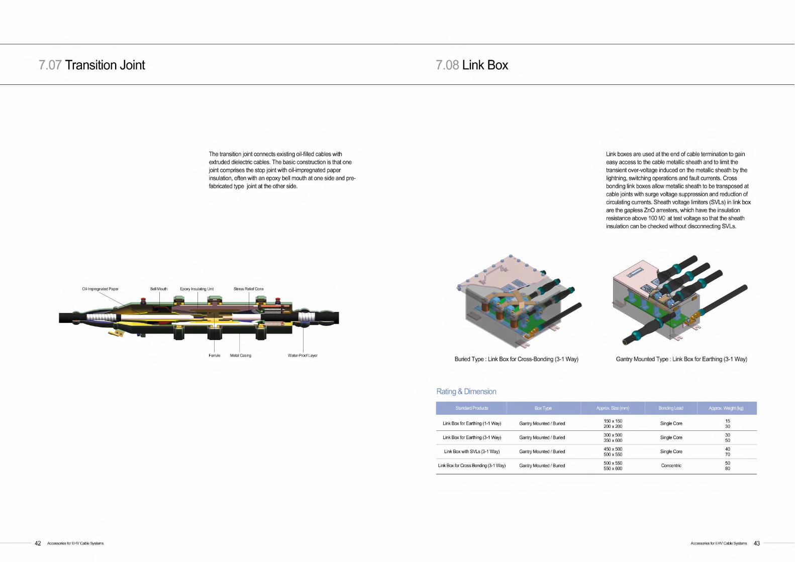
7 . 0 6 Pre-Fabricated Joint (PJ)
The pre-fabricated type joint, so called PJ, is based on theepoxy insulating unit and the EPR-based rubber stress reliefcones. Using mechanical devices, the interface pressure issafely maintained all through the operation period.
The main insulation components are factory-made and fullytested before delivering to the site. They are currentlyavailable at the voltage range up to 400kV. The maximumallowable cable conductor size is 2500mm2.
Accessories for EHV Cable Systems 4 1
7 . 0 5 Pre-Molded Joint (PMJ)
Accessories for EHV Cable Systems4 0
Rating & Dimension
Max. Voltage (kV)
Approx. Length (mm)
Approx. Max. Outer Dia. (mm)
Approx. Weight (kg)
The single piece pre-molded type rubber joint is based onsilicone insulation embedded with two semi-conductive stressrelief cones and one high voltage electrode. Without anymechanical devices, the interface pressure is safelymaintained with elastic retention of material itself. The maininsulation components are factory-made and fully tested beforedelivering to the site.
The cost-efficient and simplified design along with easy andfast installation meets the various needs of customers.Installation tools can be provided if requested by customers.The maximum allowable cable conductor size is 2500mm2.
7 2 . 5
1 0 0 0
2 0 0
9 0
1 2 3
1 4 0 0
2 3 0
1 2 0
145 ~ 170
1 5 0 0
2 5 0
1 5 0
245 ~ 300
1 7 0 0
2 7 0
2 0 0
362 ~ 420
1 8 0 0
3 1 0
2 5 0
Water-Proof Layer Joint Sleeve
Sheath Sectionalized Unit Metal CasingF e r r u l e
Rating & Dimension
Max. Voltage (kV)
Approx. Length (mm)
Approx. Max. Outer Dia. (mm)
Approx. Weight (kg)
1 4 5
1 8 0 0
2 9 0
2 2 0
1 7 0
1 8 0 0
3 2 0
2 5 0
2 4 5
2 0 0 0
3 6 0
3 0 0
4 2 0
2 2 0 0
4 0 0
3 5 0
Water-Proof Layer Epoxy Insulating Unit Stress Relief Cone
Sheath Sectionalized Unit Metal CasingF e r r u l e


Jordan Office#307 4th Fl. Mid Town Plaza, Sweifieh-Subhi Al-Omari St. P.O. Box 851885 Amman 11185 JordanTel. +962-6-583-3357 Fax. +962- 6-583-3359
UAE Office#502 Capricorn Tower, Sheikh Zayed Rd., Dubai, UAE, PO Box 113798Tel. +971-4-332-9445 Fax. +971-4-332-9446
India OfficeC-1, 3rd Fl. Community Centre (Opp. I.I.T Gate) Safdarjung Development Area, New Delhi 110016 India Tel. +91-11-4602-1657,1658 Fax. +91-11-4602-1659
Russia OfficePark Place Moscow 113/1 Leninsky Prospect E-711, Moscow 117198 RussiaTel. +7-495-956-5814 Fax. +7-495-956-5811
LSIC (Beijing Office) : LS International[Shanghai] Ltd. #05 B-17th Fl. Global Trade Center, 36 Beisanhuan-Dong RdDongcheng Dt. Beijing, ChinaTel. +86-10-5825-6011 Fax. +86-10-5825-6015
LSCT : LS Cable [Tianjin] Ltd.East of Jing-Jin, Express Yixingbu Toll Gate Beichen, Tianjin, ChinaTel. +86-22-2699-7618 Fax. +86-22-2699-7617
LSAS : LS Air-Conditioning [Shandong] Ltd.Yu-Huangling Industrial Area, Xiazhuang, Chengyang District, Qingdao, China.Tel. +86-532-8096-8888 Fax. +86-532-8096-5688
LSCW : LS Cable [Wuxi] Ltd. LS Industrial Park, Xin Mei Rd., New Dt. Wuxi 214028, China Tel. +86-510-8811-9000 Fax. +86-510-8534-5341
LSMW : LS Machinery [Wuxi] Ltd.LS Industrial Park, Xin Mei Rd., New Dt. Wuxi 214028, ChinaTel. +86-510-8299-3888 Fax. +86-510-8299-3889
LS-VINASo Dau Precint, Hong Bang Dt., Hai Phong, VietnamTel. +84-31-540750 Fax. +84-31-540241
LLSMWSuite 7A, Menara Northam, 55 Jalan SultanAhmad Shah, Penang 10050 MalaysiaTel. +60-4-588-9609(34) Fax. +60-4-588-9607
VINA-LSC1 Nui Truc Lane, Giang Van St., Ba Dinh, Hanoi, Vietnam Tel. +84-4-722-3838, 3535 Fax. +84-4-722-3030
Singapore Office300 Beach Road #25-07 The Concourse Singapore 199555Tel. +65-6342-9162~3 Fax. +65-6342-9164
Japan OfficeE 16th Fl. Akasaka Twin Tower 17-22, 2-Chome Akasaka, Minato-Ku, Tokyo, JapanTel. +81-3-3582-9129 Fax. +81-3-3582-7363
LSIC : LS International [Shanghai] Ltd.12th Fl. Huamin Empire Plaza, 726 West Yan'an Rd., Shanghai 200050 ChinaTel. +86-21-5237-3399, 8997 Fax. +86-21-5237-8996
LS Cable America, Inc.920 Sylvan Avenue, Englewood Cliffs, NJ 07632, USATel. +1-201-816-2253 Fax. +1-201-816-2984
Seoul
Head Office21st Fl. ASEM Tower, 159 Samsung-dong, Gangnam-guSeoul 135-798 KoreaTel. +82-2-2189-9114
Anyang Plant555 Hogye-dong, Dongan-guAnyang, Gyeonggi-do 431-831 KoreaTel. +82-31-428-4114
Gumi Plant190 Gongdan-dong, GumiGyeongsangbuk-do 730-708 KoreaTel. +82-54-469-7114
Indong Plant643 Jinpyeong-dong, GumiGyeongsangbuk-do 730-735 KoreaTel. +82-54-469-7050
Jeongeup Plant938 Jeongeup 3 Industrial ComplexTaegok-ri, Buk-myeon, Jeongeup Jeollabuk-do 580-812 KoreaTel. +82-63-530-4114
Jeonju Plant 778 Jeonju 3 Industrial ComplexYongnam-ri, Bongdong-eupWanju-gun, Jeollabuk-do 565-904 KoreaTel. +82-63-279-5114
R&D Center555 Hogye-dong, Dongan-guAnyang, Gyeonggi-do 431-831 KoreaTel. +82-31-450-8114
BranchesSubsidiaries
Global Network