lsn 8 clock sources and circuits - university of dayton
TRANSCRIPT

Department of
Engineering Technology
LSN 8
Clock Sources and Circuits
ECT 224 Digital Computer Fundamentals

ECT 224 Digital Computer Fundamentals [email protected]
LSN 8 – Clock Sources
• Clock sources are devices with no inputs and one
output characterized by:
– Frequency
– Duty cycle
– Magnitude
ECT 224 Digital Computer Fundamentals [email protected]
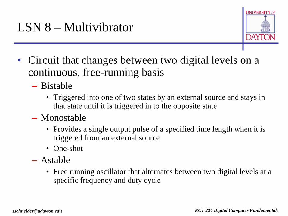
LSN 8 – Multivibrator
• Circuit that changes between two digital levels on a continuous, free-running basis
– Bistable
• Triggered into one of two states by an external source and stays in that state until it is triggered in to the opposite state
– Monostable
• Provides a single output pulse of a specified time length when it is triggered from an external source
• One-shot
– Astable
• Free running oscillator that alternates between two digital levels at a specific frequency and duty cycle
ECT 224 Digital Computer Fundamentals [email protected]
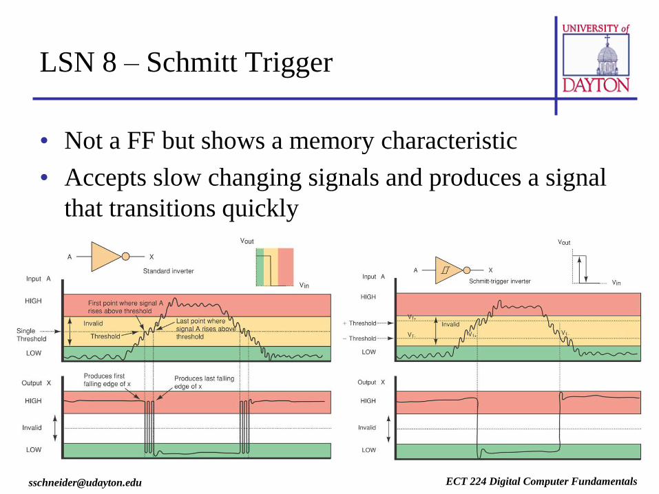
LSN 8 – Schmitt Trigger
• Not a FF but shows a memory characteristic
• Accepts slow changing signals and produces a signal
that transitions quickly

ECT 224 Digital Computer Fundamentals [email protected]
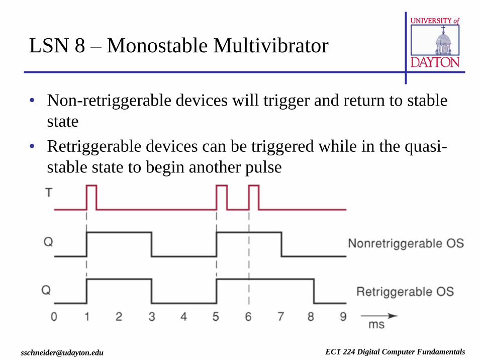
LSN 8 – Monostable Multivibrator
• Changes from stable state to quasi-stable state for
a period of time determined by external
components (usually resistors and capacitors)
ECT 224 Digital Computer Fundamentals [email protected]
LSN 8 – Monostable Multivibrator
• Non-retriggerable devices will trigger and return to stable
state
• Retriggerable devices can be triggered while in the quasi-
stable state to begin another pulse

ECT 224 Digital Computer Fundamentals [email protected]
LSN 8 – Monostable Multivibrator
• IC versions
– 74xx121 single non-retriggerable monostable multivibrator
– 74xx221 dual non-retriggerable monostable multivibrator
– 74xx122 single retriggerable monostable multivibrator
– 74xx123 dual retriggerable monostable multivibrator
ECT 224 Digital Computer Fundamentals [email protected]
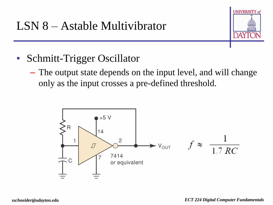
LSN 8 – Astable Multivibrator
• Schmitt-Trigger Oscillator
– The output state depends on the input level, and will change
only as the input crosses a pre-defined threshold.

ECT 224 Digital Computer Fundamentals [email protected]
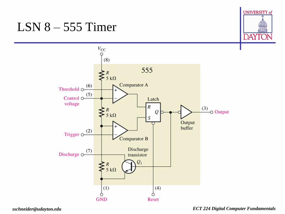
LSN 8 – 555 Timer
• Monostable (One-Shot)
– Single output pulse with adjustable pulse-width
– Triggered by a negative pulse on the trigger pin
– Useful for extending pulses
• Astable Multivibrator
– Continuous pulse train with adjustable frequency and duty
cycle
– Frequency and duty cycle set by external component values
– Useful as a timer or clock


ECT 224 Digital Computer Fundamentals [email protected]
LSN 8 – 555 Timer (Astable)
• Frequency
F = 1.44 / (R1 + 2R2)C1
• Duty cycle
DC = (R1 + R2) / (R1 + 2R2)
ECT 224 Digital Computer Fundamentals [email protected]
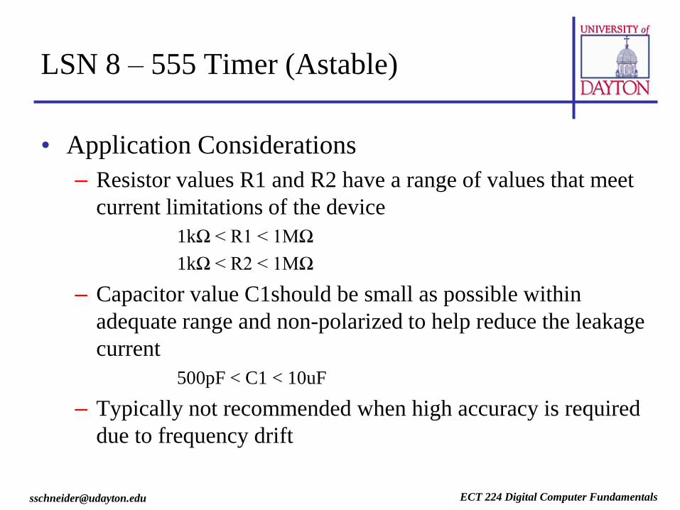
LSN 8 – 555 Timer (Astable)
• Application Considerations
– Resistor values R1 and R2 have a range of values that meet
current limitations of the device
1kΩ < R1 < 1MΩ
1kΩ < R2 < 1MΩ
– Capacitor value C1should be small as possible within
adequate range and non-polarized to help reduce the leakage
current
500pF < C1 < 10uF
– Typically not recommended when high accuracy is required
due to frequency drift

ECT 224 Digital Computer Fundamentals [email protected]
LSN 8 – Crystal Controlled Oscillators
• Uses the mechanical resonance of a physical crystal of
piezoelectric material with feedback to create a precise
frequency signal
• Increased accuracy and stability over RC oscillators
• IC or quartz crystal package

ECT 224 Digital Computer Fundamentals [email protected]
LSN 8 – Clock Circuits
• Voltage Controlled Oscillator (VCO)
– Uses a varactor diode as the principle tuning element
– The voltage controlled oscillator is tuned across its band by
applying a DC voltage to the varactor diode to vary the net
capacitance applied to the tuned circuit

ECT 224 Digital Computer Fundamentals [email protected]
LSN 8 – Clock Circuits
• Clock distribution
– Routing clock signal throughout circuit
• Clock skew
• Fan-out
• Frequency divider
– Useful in providing lower frequency clocks from a master
clock

ECT 224 Digital Computer Fundamentals [email protected]
LSN 8 – Clock Accuracy
• Measured in Parts Per Million
– One PPM (Part Per Million) is 0.0001% (1E-6)
– Calculator to determine time drift based upon PPM and
temperature
• http://www.maxim-ic.com/tools/calculators/index.cfm/calc_id/rtc
ECT 224 Digital Computer Fundamentals [email protected]
LSN 8 – Homework
• Reading
– Chapter 7.5 – 7.6
• Assignment – HW10
– Create a clock circuit that can achieve a 32.768kHz signal (Must use standard component values)
• Use a 555 timer IC (ensure the 555 is within its safe operating range)
• Use a CMOS Schmitt-trigger oscillator (74HC14)
• Find a COTS high-accuracy clock sources (think voltage and temperature compensation) and submit data sheet with a brief comment on why you think it is accurate
• References
– http://www.epanorama.net/links/oscillator.html#crystal
– http://www.electronics-tutorials.com/oscillators/oscillators.htm