lt-9048 b apex orion-lynx user manual - trango...trango systems, inc. apex orion / lynx user manual...
TRANSCRIPT

Revision 1.0.1
Doc No. LT‐9048 Rev B
Apex Orion® / Lynx All-Outdoor Ultra High Capacity FDD Point to Point Microwave System Model: TLAOx-xx, TLALx-xx
User Manual

Trango Systems, Inc. Apex Orion / Lynx User Manual v 1.1 Doc No. LT‐9048 Rev B 2
Revision History
Revision Revision Date Description
1.0.1 25 Sept 2013 Initial Release

Trango Systems, Inc. Apex Orion / Lynx User Manual v 1.1 Doc No. LT‐9048 Rev B 3
Notice
This document contains information that is confidential and proprietary to Trango Systems, Inc. No part of the content of this publication may be reproduced, modified, used, copied, disclosed, conveyed, or distributed to any party in any manner whatsoever without prior written authorization from Trango Systems, Inc. This document is provided as is, without warranty of any kind.
Trademarks
Trango Systems®, StrataLink®, and TrangoLINK Giga® are registered trademarks of Trango Systems, Inc. Other names mentioned in this publication are owned by their respective holders.
Statement of Conditions
The information contained in this document is subject to change without notice. Trango Systems, Inc. shall not be liable for errors contained herein or for incidental or consequential damage in connection with the furnishing, performance, or use of this document or equipment supplied with it.
Information to User
Any changes or modifications of equipment not expressly approved by the manufacturer could void the user’s authority to operate the equipment and the warranty for such equipment.
Trango Systems, Inc. 14118 Stowe Drive, Suite B
Poway, CA 92064
Tel.: +1 (858) 391‐0010 Fax: +1 (858) 391‐0020
Copyright © 2013 by Trango Systems, Inc. All rights reserved.
Document Number LT‐9048 Rev 1.0
Trango Systems, Inc. Apex Orion / Lynx User Manual v 1.1 Doc No. LT‐9048 Rev B 4
Contents
Contents ......................................................................................................4
Figures.........................................................................................................7
Tables ..........................................................................................................9
Introduction ..............................................................................................10 Apex Orion................................................................................................................. 10 Apex Lynx .................................................................................................................. 10
System Components ...............................................................................11
System Overview .....................................................................................12 Patent Pending Design............................................................................................ 14 Ports and Indicators ................................................................................................. 15 Antenna Connection ................................................................................................ 18 Remote Mounting ..................................................................................................... 18 Combiners for Antenna Sharing ............................................................................ 18 Power Supply ............................................................................................................ 18 Direct Power Option................................................................................................. 19 Power Over Ethernet (PoE) Option ....................................................................... 19 Traffic Capacity......................................................................................................... 19 Link Management..................................................................................................... 20 Graphical User Interface (GUI): ............................................................................. 20 Command Line Interfaces....................................................................................... 21
Radio Traffic/Management Configurations .........................................22 IBM with GE1 (RJ45) ............................................................................................... 23 IBM with GE2 (SFP)................................................................................................. 24 OBM on GE2 (SFP) ................................................................................................. 25 OBM on GE1 (RJ45)................................................................................................ 26
Features Detailed Description ...............................................................27 Traffic Capacity......................................................................................................... 27 Setting Transmit/Receive Frequency and Duplex Spacing ............................... 29 Speed Profile Setup (Modulation/Channel Bandwidth) ...................................... 30 Advanced Adaptive Coding and Modulation (AACM) ........................................ 32 Automatic Transmit Power Control (ATPC) ......................................................... 35 VLAN Traffic Support............................................................................................... 37 Multilayer Header Compression ............................................................................ 38

Trango Systems, Inc. Apex Orion / Lynx User Manual v 1.1 Doc No. LT‐9048 Rev B 5
Physical Link Aggregation ...................................................................................... 41 NOTE: PLA Is designed to be used with a single OBM connection on GE1 and a single Gigabit Traffic connection on GE2, Multiple data ports and/or IBM is not supported for PLA mode.XPIC............................................................ 43 XPIC ........................................................................................................................... 44 QoS (Quality of Service) ......................................................................................... 48 Opmode (Transmitter On/Off Control) .................................................................. 52 Rapid Port Shutdown (RPS)................................................................................... 52 Threshold Settings ................................................................................................... 53 Port Rate Limiting (Ingress) .................................................................................... 54 Status Snapshot ....................................................................................................... 54 Management Services............................................................................................. 55 Firmware Update ...................................................................................................... 56 Upgrade Procedure -TFTP ..................................................................................... 57 Upgrade Procedure -FTP........................................................................................ 59 IP Configuration ........................................................................................................ 59 GPS Coordinates ..................................................................................................... 60 Ethernet Port Settings ............................................................................................. 61
Link Planning............................................................................................63 Path Planning............................................................................................................ 63 Site Selection ............................................................................................................ 63
Installation ................................................................................................64 Safety ............................................................................................................................... 64
Basic Link Setup ......................................................................................67
Detailed Field Installation .......................................................................68 Antenna Installation ................................................................................................. 69 Power Supply and PoE Installation ....................................................................... 69 Running Cable .......................................................................................................... 70 Radio Installation onto Antenna ............................................................................. 76 Antenna Alignment................................................................................................... 81
Appendix A- Product Specifications ....................................................83 Table 1 – Maximum Transmitter Power - Apex Orion ........................................ 87 Table 2 – Maximum Transmitter Power - Apex Lynx ......................................... 87 Table 3 – Maximum Receiver Input Level (All Units) ......................................... 88 Table 4 - Receive Sensitivity (AO1 and AL2 Models) ........................................ 89
Appendix B – Radio Sub-banding.........................................................95
Appendix C- Web Interface Guide.........................................................96 Basic Web Browser Operation ............................................................................... 96 Web Page Details................................................................................................... 101

Trango Systems, Inc. Apex Orion / Lynx User Manual v 1.1 Doc No. LT‐9048 Rev B 6
Appendix D- Command Line Interface Guide ...................................119
Appendix E- SNMP OID Guide .............................................................120

Trango Systems, Inc. Apex Orion / Lynx User Manual v 1.1 Doc No. LT‐9048 Rev B 7
Figures Figure 1 OMU Functional Block Diagram......................................................................... 13
Figure 2 ODU Functional Block Diagram ......................................................................... 14
Figure 3 Apex Orion Ports and indicators ........................................................................ 15
Figure 4 Polarization Indicator ........................................................................................... 17
Figure 5 Management Configuration - IBM using GE1 .................................................. 23
Figure 6 Management Configuration - IBM using GE2 .................................................. 24
Figure 7 Management Configuration - OBM using GE2 ................................................ 25
Figure 8 Management Configuration - OBM using GE1 ................................................ 26
Figure 9 Capacity vs. Channel BW & Modulation Chart ................................................ 28
Figure 10 Advanced ACM................................................................................................... 33
Figure 11 Header Compression Packet Structure .......................................................... 39
Figure 12 PLA Block Diagram ............................................................................................ 42
Figure 13 XPIC Block Diagram .......................................................................................... 44
Figure 14 XPIC with PLA Block Diagram ......................................................................... 45
Figure 15 PLA with XPIC Capacity ........................................................................................ 46
Figure 16 Wall Mount Power Supply................................................................................. 69
Figure 17 -48 VDC Power Connector using coaxial cable ............................................ 70
Figure 18 POE-GIGE-48 ..................................................................................................... 70
Figure 19 PoE Wiring........................................................................................................... 72
Figure 20 Direct Power Connector .................................................................................... 73
Figure 21 PoE Based Cable/Grounding Diagram ........................................................... 74
Figure 22 Antenna to Radio Slip Fit Waveguide connection......................................... 76
Figure 23 Polarization Indicator ......................................................................................... 77
Figure 24 Mounting Latches ............................................................................................... 77
Figure 25 Port Sealing Components ................................................................................. 78

Trango Systems, Inc. Apex Orion / Lynx User Manual v 1.1 Doc No. LT‐9048 Rev B 8
Figure 26 STP and Fiber (PLA) Cable installed on Unit ................................................ 78
Figure 27 Port Cover/Cord Grip Installed ......................................................................... 79
Figure 28 Cord Grip Tightened (Single Cable Install) .................................................... 79
Figure 29 Ground Lug and RSSI BNC on Orion ............................................................. 80

Trango Systems, Inc. Apex Orion / Lynx User Manual v 1.1 Doc No. LT‐9048 Rev B 9
Tables Table 1: Apex Orion Part Numbers ................................................................................... 11
Table 2 Combiner Cross Reference.................................................................................. 18
Table 3 Capacity vs Modulation and Channel Size ........................................................ 39
Table 4 Max L2 Capacity by Traffic Type......................................................................... 40

Trango Systems, Inc. Apex Orion / Lynx User Manual v 1.1 Doc No. LT‐9048 Rev B 10
Introduction Thank you for purchasing the Apex All Outdoor licensed point to point microwave system. This manual is designed to provide guidance on the configuration, installation, and usage of both the Apex Orion and Apex Lynx System. For a condensed version covering basic setup and installation, please refer to the Quick Start Guide and related application notes.
Apex Orion The Apex Orion is an ultra‐high performance licensed Microwave transmission system designed to carry up to Gigabit capacity Ethernet traffic. A single link comprised of two radio units operating on a single polarization in a 60 MHz channel features up to 761 Mbps Full Duplex Layer 2 capacity for 64 byte packets and 486 Mbps for 1518 byte packets. In an XPIC or 2+0 configuration Gigabit capacities for all packet sizes can be achieved. The system is available in all the standard worldwide frequency bands from 5.9 GHz to 42 GHz and features leading system gain and high reliability.
Apex Lynx The Apex Lynx is very similar to the Apex Orion with the exception of the following items:
‐ Base capacity limited to 440 Mbps – Upgradable to 761 Mbps with license key ‐ Transmitter Power about 3 dB lower than Orion ‐ XPIC not supported ‐ Packet Buffer limited to 2 Mbytes ‐ Sync‐E and IEEE1588v2 not supported
All other features are identical to the Apex Orion. This Manual references the Apex Orion but all commands and web page functionality is the same with the exception of the items above, which are not available.

Trango Systems, Inc. Apex Orion / Lynx User Manual v 1.1 Doc No. LT‐9048 Rev B 11
System Components The basic link consists of the following items: 2 each all outdoor radio model AO1‐XX‐YYY‐ZA(Low TX) and AO1‐XX‐YYY‐ZB (High TX) 2 each Dish Antennas 2 each PoE Injector model POE‐GIGE‐48 (required only if Power over Ethernet is used) 2 each Power Supply model PSUPPLY‐WM‐48L Additional items may be needed depending on the link configuration. A List of the most common part numbers used for the system is given in Table 1.
Part Number Description
TLAO1‐XX‐YYYY‐Z Trango Apex Orion HP1 system, XXGHz, YYYY Duplex, Subband Z TLAL2‐XX‐YYYY‐Z Trango Apex Lynx HP2 system, XXGHz, YYYY Duplex, Subband Z AO1‐XX‐YYYY‐ZZ Trango Apex Orion HP1 All Outdoor Unit, XXGHz, YYYY Duplex, Subband ZZ AL2‐XX‐YYYY‐ZZ Trango Apex Lynx HP2 All Outdoor Unit,, XXGHz, YYYY Duplex, Subband ZZ PSUPPLY‐WP‐48‐L ‐48 Volt Universal Wall Mount PoE Power Supply – 1.6 Amp PSUPPLY‐1U‐48 ‐48 Volt Universal Rack mount Power Supply – 6 Amp POE‐GIGE‐48 PoE injector/Surge Suppressor for All Outdoor Units CBLDAT‐RIU5 1+1 Interface Cable for Apex Orion – 2 required per link CBLDAT‐RSSI BNC‐M to Banana plug cable for RSSI voltage measurement CBLDAT‐XPIC‐9 XPIC Coaxial Cable set (2ea 9 ft cables) with heat shrink – 2 required per link PLAKIT‐9‐M PLA kit (2ea MM SFP modules and 2ea 9 ft Fiber cables) – 2 required per link AO‐KEY‐A256 Software Key to enable AES 256 for one pair of Apex Orion radios AL‐KEY‐A256 Software Key to enable AES 256 for one pair of Apex Lynx radios AL‐KEY‐MAX Software Key to enable 761 Mbps Capacity of Apex Lynx for one pair of radios SFP‐GigE‐C SFP 1000BaseT Copper RJ45 SFP‐GigE‐S SFP Fiber Single Mode (SM) Module SFP‐GigE‐M SFP Fiber Multi Mode (MM) Module SFP‐Console Serial Console SFP Module with DB9 Serial interface
Table 1: Apex Orion Part Numbers

Trango Systems, Inc. Apex Orion / Lynx User Manual v 1.1 Doc No. LT‐9048 Rev B 12
System Overview The TrangoLINK® Apex Orion is an ultra high performance all outdoor point‐to‐point wireless microwave system designed for Carrier, Enterprise, and Service Provider networks using the 6‐42 GHz licensed spectrum. Key features include:
1) Up to 761 Mbps full duplex Layer 2 Ethernet throughput in a 56/60 MHz channel single polarization.
2) MultiLayer Header Compression increases small packet capacity dramatically by replacing MAC, IP, VLAN, TCP and UDP headers with small tags during transmission over the air.
3) Cross Polarization Interference Cancellation (XPIC) support for up to 1.5 Gbps full duplex throughput in a 56/60 MHz channel (Apex Orion only).
4) Spectral efficiency up to 25 bits/Hz with 1024QAM modulation in an XPIC configuration. Up to 12.5 bits/Hz without XPIC.
5) Physical Link Aggregation(PLA) to support XPIC and 2+0 operation working in conjunction with ACM – not dependent on multiple traffic flows like LACP.
6) Sync‐ E clock transport over microwave and IEEE1588v2 timing over packet support (Transparent Clock AND fixed latency) (Apex Orion Only).
7) Ultra low fixed latency and jitter in all ACM modes.
8) Hitless advanced ACM with 9 levels to provide higher capacity in degraded channel conditions.
9) ATPC works in conjunction with ACM to increase transmit power level on ACM downshift for up to 8 dB increase in system gain during fading.
10) AES‐256 Encryption (Requires Software Key)
11) Diffserv, and VLAN QoS fully configurable on a per port basis
12) Up to 8 Mbyte packet buffer to absorb bursty traffic and increase TCP performance over high latency networks (2 Mbytes for Apex Lynx)
The system includes interfaces for 10/100/1000BaseT and Fiber, a separate Physical Link Aggregation, GigE SFP, and XPIC in/out interfaces.
Sync‐E recovers Ethernet timing from the RJ45 interface and passes the timing over the link to be used as a source for the far end Ethernet ports. To support IEEE1588v2 timing over packet, PTP messages are treated as highest priority and the correction field is updated at the far end of the link to reflect the link residence time.

Trango Systems, Inc. Apex Orion / Lynx User Manual v 1.1 Doc No. LT‐9048 Rev B 13
The Apex Orion was created to allow the highest performance possible across all standard frequency bands and TR spacings, best heat dissipation for operation in hot climates, and easy sparing options. Each unit consists of an Outdoor Modem Unit (OMU) and an Outdoor RF unit (ODU), connected via a single coaxial cable.
Figures 1 and 2 show the functional block diagram of the system as they are divided between the OMU and ODU.
IBM
Pack
et F
ragm
enta
tion
Hea
der C
ompr
essi
on
Phy
sica
l Lin
k A
ggre
gatio
n
1588
1588
Figure 1 OMU Functional Block Diagram

Trango Systems, Inc. Apex Orion / Lynx User Manual v 1.1 Doc No. LT‐9048 Rev B 14
Control CPU
N-Plexer
TX(350 MHz)
RX(140 MHz)
LocalOscillator
TransmitUpconverter
ReceiveDownconvertor
Diplexer
PowerAmplifier
Low noiseAmplilfier
Power Supply
-48V
CoaxialCable to the
OMU
Wave-guideport
ODU
OMU
Figure 2 ODU Functional Block Diagram
The Apex Orion is a Frequency Division Duplex (FDD) radio which provides low latency of less than 300 microseconds (μs), over 1.45 million packets per second, and up to 761 Mbps of full duplex Layer 2 capacity. Standard features include Quality‐of‐Service (QoS) traffic prioritization on a per port basis, as well as Advanced Adaptive Coding and Modulation (AACM) to improve performance during weather related signal degradation.
Apex Orion supports either direct ‐48 Volt DC power or power over Ethernet using a PoE injector device provided by Trango. The PoE injector has interfaces for Ethernet traffic and management, as well as support for redundant power supplies.
Patent Pending Design
The Apex Orion utilizes patent pending architecture consisting of an outdoor Modem Unit (OMU) and an Outdoor Radio Unit (ODU). This unique design has several benefits:
1) Support for all licensed frequencies from 6‐42 GHz via a common IF/telemetry/power interface.
2) Improved temperature performance due to the increased surface area of the unit.
3) Common ODUs with Trango split architecture and ApexPlus systems to simplify field sparing requirements.
4) System Gain equivalent to Trango Split architecture systems, among the highest in the industry.

Trango Systems, Inc. Apex Orion / Lynx User Manual v 1.1 Doc No. LT‐9048 Rev B 15
Ports and Indicators
The Figure below shows the various ports on the Apex Orion Unit.
Figure 3 Apex Orion Ports and indicators
100/1000BaseT RJ45 Connector (GE1) ‐ This is the main native Ethernet data port. It is used for traffic, In Band and Out of band management. This port supports PoE using Cat5e or Cat 6 with 8 conductors and a shield. All 8 positions carry ‐48 VDC and the ground return is via the shield. Max length is 250 feet when used with PoE.
SFP Port (GE2) – SFP Port supports a second native 100/1000BaseT or LC fiber Ethernet connection for traffic, In Band and Out of Band management. SFP modules are available to support each as follows:
a. SFP‐GigE‐C‐1– Copper RJ45 module to support 100/1000BaseT
b. SFP‐GigE‐S – Single Mode Fiber for long haul
c. SFP‐GigE‐M– Multimode Fiber for short haul
PLA port – SFP Fixed 1000 Mbps copper/MM/SM Fiber Gore Air
Vent
GE1 port – RJ45 100/1000 Mbps Data/ Mgmt Port + Power (PoE) ( )
Direct Power Jack with Link indicator LED and Reset Button above
1+1 Comm port
Mounting Latch
Grounding Lug ‐ OMU
ODU
Coaxial OMU to ODU Cable
XPIC In ‐ SMA F connector with cap
GE2 port – SFP Fixed 1000 Mbps Data/ Mgmt Port or Console copper/MM/SM Fiber
XPIC Out – SMA F connector with cap
GND‐48V
Trango Systems, Inc. Apex Orion / Lynx User Manual v 1.1 Doc No. LT‐9048 Rev B 16
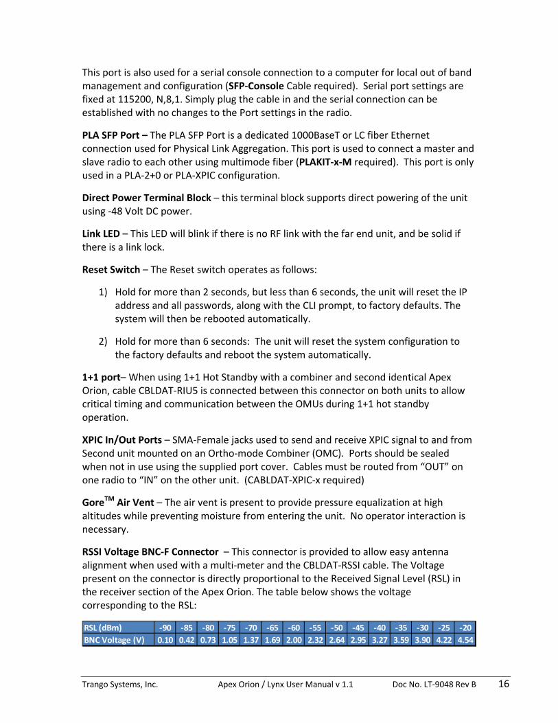
This port is also used for a serial console connection to a computer for local out of band management and configuration (SFP‐Console Cable required). Serial port settings are fixed at 115200, N,8,1. Simply plug the cable in and the serial connection can be established with no changes to the Port settings in the radio.
PLA SFP Port – The PLA SFP Port is a dedicated 1000BaseT or LC fiber Ethernet connection used for Physical Link Aggregation. This port is used to connect a master and slave radio to each other using multimode fiber (PLAKIT‐x‐M required). This port is only used in a PLA‐2+0 or PLA‐XPIC configuration.
Direct Power Terminal Block – this terminal block supports direct powering of the unit using ‐48 Volt DC power.
Link LED – This LED will blink if there is no RF link with the far end unit, and be solid if there is a link lock.
Reset Switch – The Reset switch operates as follows:
1) Hold for more than 2 seconds, but less than 6 seconds, the unit will reset the IP address and all passwords, along with the CLI prompt, to factory defaults. The system will then be rebooted automatically.
2) Hold for more than 6 seconds: The unit will reset the system configuration to the factory defaults and reboot the system automatically.
1+1 port– When using 1+1 Hot Standby with a combiner and second identical Apex Orion, cable CBLDAT‐RIU5 is connected between this connector on both units to allow critical timing and communication between the OMUs during 1+1 hot standby operation.
XPIC In/Out Ports – SMA‐Female jacks used to send and receive XPIC signal to and from Second unit mounted on an Ortho‐mode Combiner (OMC). Ports should be sealed when not in use using the supplied port cover. Cables must be routed from “OUT” on one radio to “IN” on the other unit. (CABLDAT‐XPIC‐x required)
GoreTM Air Vent – The air vent is present to provide pressure equalization at high altitudes while preventing moisture from entering the unit. No operator interaction is necessary.
RSSI Voltage BNC‐F Connector – This connector is provided to allow easy antenna alignment when used with a multi‐meter and the CBLDAT‐RSSI cable. The Voltage present on the connector is directly proportional to the Received Signal Level (RSL) in the receiver section of the Apex Orion. The table below shows the voltage corresponding to the RSL:
RSL (dBm) ‐90 ‐85 ‐80 ‐75 ‐70 ‐65 ‐60 ‐55 ‐50 ‐45 ‐40 ‐35 ‐30 ‐25 ‐20BNC Voltage (V) 0.10 0.42 0.73 1.05 1.37 1.69 2.00 2.32 2.64 2.95 3.27 3.59 3.90 4.22 4.54

Trango Systems, Inc. Apex Orion / Lynx User Manual v 1.1 Doc No. LT‐9048 Rev B 17
OMU to ODU cable– This cable carries the Transmit IF signal, Receive IF signal, supply voltage, and control signaling to the ODU. The cable is sealed using heat shrink to prevent water ingress and should only be changed by Trango factory certified personnel.
Mounting Latches – Four latches are provided to allow easy attachment of the Apex Orion to the standard antennas, combiners and remote mounts. Two of the latches have keyholes to allow locking the unit to deter theft and/or secure the unit.
Polarization Indicators – The letters “H” and “V” are die cast on the OMU housing perimeter to assist in mounting the Apex Orion to the antenna in the correct polarization. When mounted directly to an antenna, the letter that is at the 12 O’Clock position will always indicate the polarization being utilized for transmit and receive.
Figure 4 Polarization Indicator
Grounding Lug – OMU – The ground lug provided on the OMU should be connected to the tower/structure leg per the grounding section recommendations.
Grounding Lug – ODU ‐ The ground lug provided on the ODU should be connected to the tower/structure leg per the grounding section recommendations.
“H” polarization indicator

Trango Systems, Inc. Apex Orion / Lynx User Manual v 1.1 Doc No. LT‐9048 Rev B 18
Antenna Connection
The ODU portion of the Apex Orion utilizes a slip fit connection that makes installation simple. The ODUs are all designed to mount to a circular waveguide antenna or combiner with the exception of the 6 GHz models which use a rectangular waveguide. For 7 to 42 GHz models, simply rotating the Apex Orion will change the antenna polarization being used. Contact Trango for a list of compatible antennas
Remote Mounting
When using the Apex Orion with non‐Trango antennas, a Remote Mount plus flex waveguide may be needed. The waveguide flanges are available for mounting all standard waveguide sizes. Contact Trango for a list of compatible Remote mounts for various waveguide flange configurations.
Combiners for Antenna Sharing
The Apex Orion unit is designed with an easy slip fit interface to the antenna. If desired, two units may be connected to the same antenna for 1+1 hot standby application or to aggregate two channels for more capacity. XPIC requires the use of an Ortho‐mode Combiner (OMC‐XX) or two separate antennas. Trango can provide multiple combiner options based on the customer applications as the table shows below:
Table 2 Combiner Cross Reference
Contact Trango for a list of compatible Combiners based on your specific application.
Power Supply
Trango can provide power supplies for rack mount and desktop applications. The PSUPPLY‐1U‐48 is a rack mount power supply with 6.0 Amp capacity that can support multiple co‐located Apex Orion units. The PSUPPLY‐WP‐48‐L is a wallmount PoE/direct power supply with 1.6 Amp capacity and is only recommended for a single Apex Orion unit.

Trango Systems, Inc. Apex Orion / Lynx User Manual v 1.1 Doc No. LT‐9048 Rev B 19
Direct Power Option
The Apex Orion can be direct powered using a ‐48 Volt DC source with a terminal block connection at the unit. The length of the cable varies on the gauge of the wire being used, but in general longer distances can be achieved than using the PoE option since the voltage drop is less. As long as the minimum voltage is maintained at the Apex Orion unit, the system will operate. This option is also preferred for applications using fiber for the data.
Power Over Ethernet (PoE) Option
When utilized with a PoE‐GigE‐48 PoE injector, the Apex Orion can be powered over the same Cat5e/Cat6 Shielded Twisted Pair (STP) that is used for the Data and in‐band management connection. Surge suppression and provision for redundant power supplies are provided with a single PoE‐GigE‐48 device.
Traffic Capacity
With QAM1024 modulation in a 56/60 MHz channel, the link can support capacities up to 761 Mbps full duplex for 64 Byte packets and 486 Mbps for 1518 byte packets and higher. These numbers are based on a single VLAN with IPv4 traffic and Header Compression enabled. With PLA and XPIC full Gigabit speeds can be supported regardless of packet size. Aggregate numbers, which are sometimes used for comparison, are twice the numbers shown above.

Trango Systems, Inc. Apex Orion / Lynx User Manual v 1.1 Doc No. LT‐9048 Rev B 20
Link Management The Apex Orion can be managed through web, Command Line Interface, Console Port, or SNMP as described below:
Graphical User Interface (GUI):
Web Browser: Remote access via in band and out of band methods with view and configuration level access (single user + password). Each web page contains the following common elements: ‐ Status bar at the top right of the page showing the local and remote link
RSSI, MSE, Modulation level, Unit ID and IP address. These are updated approximately every 5 seconds.
‐ Submit, Save Changes, Reboot, and Config View Mode buttons.
The view‐only web interface is entered using any standard web browser to access the unit and entering user: admin, pw: trango when prompted. To make changes to system parameters, the config mode must be entered by clicking on the Config Mode button and entering user: config, pw: trango at the prompt. After changes are made in config mode, click on the Submit button to make the change to the system. If the change is acceptable, click the Save Changes button to save the changes into FLASH memory. IMPORTANT: If the changes are not saved using the Save Changes button, the previously saved changes will take effect upon a reboot or repower of the radio unit. The Save Changes button will save all changes made across multiple web pages as long as the Submit button was used on each web page
The Apex Orion is compatible with any standard web browser such as Internet Explorer, Chrome, Firefox, and Safari. For a detailed description of the web interface, please see Appendix C ‐ Web Interface Guide

Trango Systems, Inc. Apex Orion / Lynx User Manual v 1.1 Doc No. LT‐9048 Rev B 21
Command Line Interfaces
SSH – Encrypted remote access via in band and out of band methods with separate view and configuration level access (password protected). Telnet – Remote access via in band and out of band methods with separate view and configuration level access (password protected). Console – Local Access using a serial cable for bench configuration with separate view and configuration level access (password protected). For a detailed description of the commands available, please see the Command Line Interface Guide
SNMP Management
Remote control and monitoring via in‐band and out‐of band methods using any third party Network Management Software (NMS). Standard MIB II System Level and Enterprise MIB Blocks are supported with monitoring for all major link health and traffic related metrics. For a detailed description of the SNMP Object IDs available, please see Appendix E ‐ SNMP Object ID (OID) Guide. SNMP Traps may be set up to allow monitoring of various parameter thresholds with any third party Trap Management software. Multiple IP addresses can be assigned to all traps.

Trango Systems, Inc. Apex Orion / Lynx User Manual v 1.1 Doc No. LT‐9048 Rev B 22
Radio Traffic/Management Configurations The radio unit has two ports that can be configured for In‐band management (IBM) or Out of band management (OBM) depending on the preference of the user. For VLAN tagged traffic entering the radio, the operator must add the VLAN membership by port to each unit. Adding a VLAN ID to a port adds both the data port (GE1 or GE2) and the modem port as members of that VLAN. Valid VLAN IDs are from 2‐4085. At time of shipment only the VLAN ID 1 is present on the ports (default VLAN) Any other VLANs required must be added before traffic on that VLAN will flow. See VLAN Traffic Support section and the vlan_add and vlan_remove commands in the CLI Guide for more information. The block diagrams below show the flow of both payload and management traffic for the four options as it enters the radio unit from the network or radio side:

Trango Systems, Inc. Apex Orion / Lynx User Manual v 1.1 Doc No. LT‐9048 Rev B 23
IBM with GE1 (RJ45) This is the default Configuration using the built In RJ45 for both service and management traffic. GE2 is available for service traffic. See the Figure below:
RADIO CPU
RADIO MODEM
GE1Copper
Port
GE2SFP Port
RADIO INTERNAL SWITCH
PLASFP Port
RF Section
IBM = On Management Port= GE1
GE1, CPU and Modem Ports are members of Internal VLAN
to allow radio management
Main Data Paths – Data flows from GE1 to Modem and from
GE2 to Modem
IF PLA Active Traffic split in Modem to Slave Unit
PLA
Figure 5 Management Configuration ‐ IBM using GE1

Trango Systems, Inc. Apex Orion / Lynx User Manual v 1.1 Doc No. LT‐9048 Rev B 24
IBM with GE2 (SFP) In this configuration both service and management traffic is on GE2 (SFP). GE1 is available for service traffic only. See the Figure below:
IBM = On Management Port= GE2
RADIO CPU
RADIO MODEM
GE1Copper
Port
GE2SFP Port
RADIO INTERNAL SWITCH
PLASFP Port
RF Section
GE2, CPU and Modem Ports are members of Internal VLAN to allow management of radio
Main Data Paths – Data flows from GE1 to Modem and from
GE2 to Modem
IF PLA Active Traffic split in Modem to Slave Unit
PLA
Figure 6 Management Configuration ‐ IBM using GE2

Trango Systems, Inc. Apex Orion / Lynx User Manual v 1.1 Doc No. LT‐9048 Rev B 25
Traffic on GE1(RJ45) and OBM on GE2 (SFP) In this configuration service traffic is on GE1 and management is on GE2. See the Figure below:
IBM = Off Management Port = GE2
RADIO CPU
RADIO MODEM
GE1Copper
Port
GE2SFP Port
RADIO INTERNAL SWITCH
PLASFP Port
RF Section
GE2 dedicated connection to CPU - For out of band
management only
Main Data Path – All traffic forwarded to Modem port
IF PLA Active Traffic split in Modem to Slave Unit
PLA
Figure 7 Management Configuration ‐ OBM using GE2

Trango Systems, Inc. Apex Orion / Lynx User Manual v 1.1 Doc No. LT‐9048 Rev B 26
Traffic on GE2 (SFP) and OBM on GE1 (RJ45) In this configuration service traffic is on GE2 only and management is on GE1. See the Figure below:
RADIO CPU
RADIO MODEM
GE1Copper
Port
GE2SFP Port
RADIO INTERNAL SWITCH
PLASFP Port
RF Section
GE1 dedicated connection to CPU - For out of band
management only
Main Data Path – All traffic forwarded to Modem port
IF PLA Active Traffic split in Modem to Slave Unit
PLA
IBM = Off Management Port = GE1
Figure 8 Management Configuration ‐ OBM using GE1

Trango Systems, Inc. Apex Orion / Lynx User Manual v 1.1 Doc No. LT‐9048 Rev B 27
Features Detailed Description This section describes the key features of the system and explains the related commands required for implementation on the link. Additional information is provided in the Command Line Interface (CLI) Guide and the Appendix C ‐ Web Browser Guide.
Traffic Capacity
With QAM1024 modulation in a 56/60 MHz channel, the link can support capacities up to 761Mbps full duplex or 1.5 Gbps aggregate, including the Multilayer Header compression. Header compression is always active unless disabled by the user.
The charts below shows the Layer 2 capacity of the Apex Orion for the available channel sizes for a single VLAN with IPV4. Capacities for IPV6 or packets using TCP and UDP will be higher than these numbers.
IPV4+VLAN for 64 byte packets in Mbps (Full Duplex) – HC On
BW(MHz) QPSK 8PSK 16
QAM 32
QAM 64
QAM 128 QAM
256 QAM
512 QAM
1024 QAM
3.5 8.7 13.2 17.8 22.0 26.8 31.4 35.8 40.4 43.9
3.75 9.5 14.4 19.3 23.8 29.1 34.0 38.9 43.8 47.5
5 12.7 19.1 25.6 31.6 38.6 45.0 51.5 58.0 63.0
7 16.6 24.9 33.4 41.2 50.3 58.7 67.8 75.6 82.1
8.33 21.4 32.1 43.1 53.1 64.7 75.6 86.4 97.3 105.6
10 24.7 37.1 49.8 61.3 74.8 87.4 99.9 112.4 122.1
12.5 32.0 48.3 64.7 79.7 97.2 113.5 129.7 146.0 158.6
14 36 54 73 90 109 128 146 165 179
20 52 78 105 129 147 184 210 236 257
25 65 97 130 161 196 229 262 295 320
28/30 77 116 156 196 234 273 312 351 382
40 104 157 210 258 315 368 420 473 514
50 119 189 258 318 387 452 517 582 632
55/56/60 155 233 312 384 469 547 625 704 761

Trango Systems, Inc. Apex Orion / Lynx User Manual v 1.1 Doc No. LT‐9048 Rev B 28
IPV4+VLAN for 1518 Byte Packets in Mbps (Full Duplex) HC On
BW(MHz) QPSK 8PSK 16
QAM 32
QAM 64
QAM 128 QAM
256 QAM
512 QAM
1024 QAM
3.5 5.5 8.4 11.3 13.9 17 19.9 22.7 25.6 27.8
3.75 6.0 9.1 12.2 15.1 18.4 21.6 24.7 27.8 30.2
5 8.0 12.1 16.2 20 24.5 28.6 32.7 36.8 40.0
7 10.5 15.5 21.2 26.2 31.9 37.3 42.6 48.0 52.1
8.33 13.5 20.4 27.3 33.7 41.1 48 54.8 61.7 67.1
10 15.7 23.6 31.6 38.9 47.5 55.5 63.4 71.4 77.5
12.5 20.0 30.6 41.1 50.6 61.7 72.1 80.4 92.7 100.7
14 23 34 46 57 69 81 93 104 113
20 33 49 66 82 100 116 133 150 163
25 41 62 83 102 124 145 166 187 203
28/30 49 74 99 122 148 173 198 223 242
40 66 99 133 164 200 234 267 300 326
50 78 122 164 202 246 287 328 369 401
55/56/60 98 148 198 244 297 347 397 447 486
Figure 9 Capacity vs. Channel BW & Modulation Chart
Apex Orion has no capacity license keys and all modulations and capacities are available to the user.
Apex Lynx comes standard with 440 Mbps max capacity and can be upgraded to full capacity with an optional software license key. All modulations and bandwidths are still available to the user but the rate is internally capped to 440 Mbps.

Trango Systems, Inc. Apex Orion / Lynx User Manual v 1.1 Doc No. LT‐9048 Rev B 29
Setting Transmit/Receive Frequency and Duplex Spacing
The frequency of operation for each radio is based on the license issued to the operator. Additionally, each unit has a specific range of frequencies that are allowed. To set the correct frequency, the frequency duplex must first be verified, and then the transmit frequency set. The receive frequency will be automatically set by the system based on the sub‐band suffix (A or B) and the Frequency Duplex spacing. Normally the Frequency Duplex will not need to be changed.
The system will only restrict user set frequencies based on the ODU frequency range. It is up to the operator to ensure that the correct frequency and channel bandwidth are used in accordance with the issued license.
IMPORTANT: When changing frequency on an active link, the link will be lost. Always change the far end of the link first to avoid losing connection to the radio. When in doubt, use the reload in x command to schedule the system to return to the last known good configuration after x minutes.
Setup via Web: 1) Login to Web Config Mode on far end radio – Link Setup>Link page 2) Verify the ODU Power is on – If not click the ODU Power button to “on” and click
“submit”. 3) Verify the Freq Duplex is correct and change if necessary 4) Select the desired Tx Frequency in .25 MHz increments 5) Click the Submit button 6) Repeat steps 1‐5 for the local radio 7) Verify the link is locked by observing the status at the top of the web page. 8) Click the Save Changes button on both ends of the link to make the change
permanent.
Setup via CLI: 1) Log in to Config Node on far end radio 2) Verify the ODU power is “on” by running the odupower command. If power is
off, run the odupower on command to turn on the power to the ODU. 3) Run freq_duplex <TR spacing> command to set the desired T/R spacing. (Only
required if the duplex is not set properly) 4) Run freq <tx freq> command and enter the desired transmit frequency – This will
change both the transmit and receive frequency. 5) Repeat Steps 1‐4 for local radio – Transmit freq on local radio should be the
same as the Receive freq on the remote radio. 6) Verify the link is locked by running linktest command on both radios 7) Run config save command to make changes permanent.

Trango Systems, Inc. Apex Orion / Lynx User Manual v 1.1 Doc No. LT‐9048 Rev B 30
Speed Profile Setup (Modulation/Channel Bandwidth)
The user has control of both the channel bandwidth used by the system and the modulation levels used by the system. The main command used to control these parameters is the speed command.
For flexibility in terms of system gain and link capacity, a wide range of channel sizes is supported.
Channel bandwidth options are 3.5, 3.75, 5, 7, 8.33, 10, 12.5, 14, 20, 25, 28/30, 40, 50 and 55/56/60 Mhz. Wider channels allow higher traffic capacities at the expense of receive sensitivity, while smaller channels provide lower capacities with higher system gain and better co‐location performance. The chart below shows the number of non overlapping channels that can be co‐located on the same path.
Modulation options are QAM1024, QAM512, QAM256, QAM128, QAM64, QAM32, QAM16, 8PSK, and QPSK. Higher modulation levels provide more radio link capacity at the expense of receive sensitivity while lower levels provide lower capacity and better receive sensitivity.
In addition to setting the bandwidth, setting a min and max modulation that are different will activate the AACM feature. AACM will operate automatically within the limits specified based on the mean squared error (MSE) which is measured by the modem. The MSE thresholds for downshift and upshift are user modifiable although the default values have been thoroughly tested and do not need to be changed in most cases.
Typically for best overall performance the user would select QPSK as the min mod and QAM1024 as the highest modulation. In longer links the radio may not have enough signal strength to achieve 1024 QAM – In this case setting the max modulation to the maximum achievable is recommended. If the min and max mod levels are the same, effectively AACM is disabled and the link will unlock if the MSE drops below a level not sustainable for that modulation.
Setup via Web: 1) Login to Web Config Mode on far end radio – Link Setup>Link page. 2) Select the desired Current Channel BW from the drop down. 3) Select the Min Modulation from the dropdown menu. 4) Select the Max Modulation from the dropdown menu. 5) Click the Submit button. 6) Repeat steps 1‐5 for the local radio. The settings must match the far end radio. 7) Verify that the link is locked by observing the status at the top of the web page. 8) Click the Save Changes button on both ends of the link to make the change
permanent.

Trango Systems, Inc. Apex Orion / Lynx User Manual v 1.1 Doc No. LT‐9048 Rev B 31
Setup via CLI: 1) Log in to Config Node on far end radio. 2) Run speed <bw> <max mod> <min mod> command to set the desired channel
bandwidth, max mod, and min mod. Command Detail: speed <bw> <max mod> <min mod> where <bw> = 3, 4, 5, 7, 8, 10, 12, 14, 20, 25, 30, 40, 50, 60; <mod_min > and <mod_max> = QPSK, 8PSK, 16QAM, 32QAM, 64QAM, 128QAM, 256QAM, 512QAM, 1024QAM. Special Notes for <bw> :
3 = 3.5 MHz 4 = 3.75 MHz 8 = 8.33 MHz 12 = 12.5 MHz 30 = 28 MHz ITU/ETSI and 30 MHz FCC/ANSI compliant 60 = 55 and 56 MHZ ITU/ETSI and 60/80 MHz FCC/ANSI compliant
3) Repeat Steps 1‐2 for local radio – The settings must match the far end radio. 4) Verify the link is locked by running linktest command on both radios 5) Run config save command on both radios to make changes permanent.
Trango Systems, Inc. Apex Orion / Lynx User Manual v 1.1 Doc No. LT‐9048 Rev B 32
Advanced Adaptive Coding and Modulation (AACM)
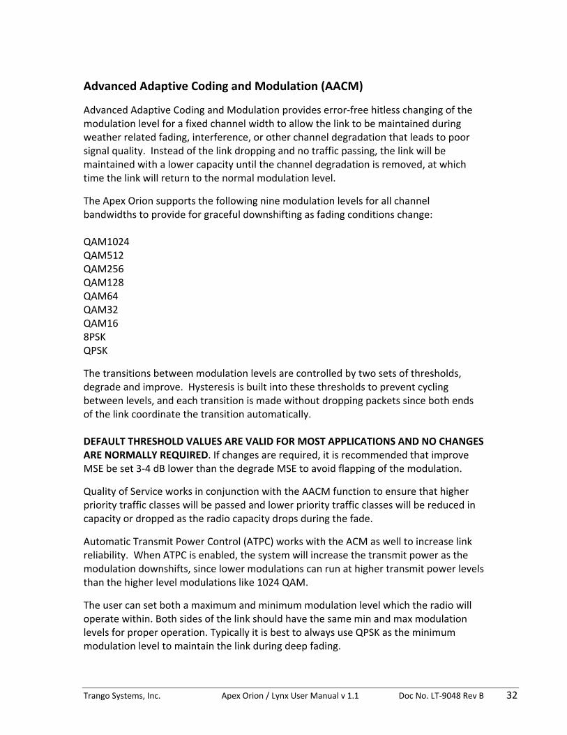
Advanced Adaptive Coding and Modulation provides error‐free hitless changing of the modulation level for a fixed channel width to allow the link to be maintained during weather related fading, interference, or other channel degradation that leads to poor signal quality. Instead of the link dropping and no traffic passing, the link will be maintained with a lower capacity until the channel degradation is removed, at which time the link will return to the normal modulation level.
The Apex Orion supports the following nine modulation levels for all channel bandwidths to provide for graceful downshifting as fading conditions change: QAM1024 QAM512 QAM256 QAM128 QAM64 QAM32 QAM16 8PSK QPSK
The transitions between modulation levels are controlled by two sets of thresholds, degrade and improve. Hysteresis is built into these thresholds to prevent cycling between levels, and each transition is made without dropping packets since both ends of the link coordinate the transition automatically. DEFAULT THRESHOLD VALUES ARE VALID FOR MOST APPLICATIONS AND NO CHANGES ARE NORMALLY REQUIRED. If changes are required, it is recommended that improve MSE be set 3‐4 dB lower than the degrade MSE to avoid flapping of the modulation.
Quality of Service works in conjunction with the AACM function to ensure that higher priority traffic classes will be passed and lower priority traffic classes will be reduced in capacity or dropped as the radio capacity drops during the fade.
Automatic Transmit Power Control (ATPC) works with the ACM as well to increase link reliability. When ATPC is enabled, the system will increase the transmit power as the modulation downshifts, since lower modulations can run at higher transmit power levels than the higher level modulations like 1024 QAM.
The user can set both a maximum and minimum modulation level which the radio will operate within. Both sides of the link should have the same min and max modulation levels for proper operation. Typically it is best to always use QPSK as the minimum modulation level to maintain the link during deep fading.

Trango Systems, Inc. Apex Orion / Lynx User Manual v 1.1 Doc No. LT‐9048 Rev B 33
The AACM feature is automatically enabled when the speed profile is setup with min and max modulation levels that are not the same, and a link is established.
The Figure below shows the AACM in action.
Figure 100 Advanced ACM
Setup : See Speed Profile Setup for Min/Max Modulation setup
This section covers AACM Threshold changes, which normally should be left in the factory default settings.
Threshold Change via Web (Changes from default values typically not required): 1) Login to Web Config Mode on far end radio – Advanced Settings>ACM page. 2) Adjust the thresholds for improve and degrade MSE if required‐ It is
recommended that improve MSE be set 3‐4 dB lower than the degrade MSE to to avoid flapping of the modulation.
3) Click the Submit button. 4) Repeat steps 1‐3 for the local radio. The settings must match the far end radio. 5) Verify that the link is locked by observing the status at the top of the web page. 6) Click the Save Changes button on both ends of the link to make the change
permanent.
Threshold Change via CLI (Changes from default values typically not required): 1) Log in to Config Node on far end radio.
Trango Systems, Inc. Apex Orion / Lynx User Manual v 1.1 Doc No. LT‐9048 Rev B 34
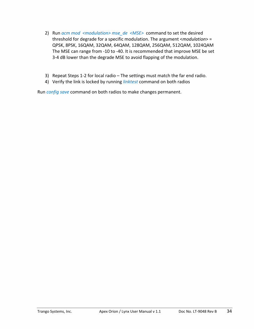
2) Run acm mod <modulation> mse_de <MSE> command to set the desired threshold for degrade for a specific modulation. The argument <modulation> = QPSK, 8PSK, 16QAM, 32QAM, 64QAM, 128QAM, 256QAM, 512QAM, 1024QAM The MSE can range from ‐10 to ‐40. It is recommended that improve MSE be set 3‐4 dB lower than the degrade MSE to avoid flapping of the modulation.
3) Repeat Steps 1‐2 for local radio – The settings must match the far end radio. 4) Verify the link is locked by running linktest command on both radios
Run config save command on both radios to make changes permanent.

Trango Systems, Inc. Apex Orion / Lynx User Manual v 1.1 Doc No. LT‐9048 Rev B 35
Automatic Transmit Power Control (ATPC)
Automatic Transmit Power Control (ATPC) is a mechanism that controls the transmitter power level on one radio to achieve a desired RSSI on the other radio. A target RSSI is set, and when ATPC is enabled, the current RSSI is monitored periodically. If the RSSI drops below the target or is too far above the target, messages are sent over the link to the transmitting side to request a power up or power down until the RSSI is within 2 dB of the target RSSI.
On the transmitting side, a request coming in from the far end will be honored as long as the request for power up or power down falls within the usable power range. The minimum power is ODU dependent and is typically between 0 and 6 dBm, but the maximum is set using the atpc max_power command. For each modulation, different maximum transmit power levels can be set based on the radio model used.
ATPC works with the ACM to increase link reliability. When ATPC is enabled, the system will increase the transmit power as the modulation downshifts, since lower modulations can run at higher transmit power levels than the higher level modulations like 1024 QAM.
The user needs to set the ATPC max power levels for each modulation, set the Target RSSI to the level that the link would normally be operating, and then enable ATPC. This must be done on both ends of the link.
Setup via Web 1) Login to Web Config Mode on far end radio – Advanced Settings>ATPC page. 2) Enter the ATPC max power levels based on the model of ODU used or levels
approved(must be less than the max for the model) 3) Enter the Target RSSI to the RSSI that the link is normally going to operate and
which is confirmed upon installation and alignment. 4) Click the ATPC “ON” button 5) Click the Submit button. 6) Repeat steps 1‐4 for the local radio. The settings should match the far end radio. 7) Verify that the link is locked by observing the status at the top of the web page. 8) Click the Save Changes button on both ends of the link to make the change
permanent.
Setup via CLI (Changes from default values typically not required): 1) Log in to Config Node on far end radio. 2) Run atpc max_power <modulation> <max power in dBm> command to set the
max power levels based on the model of ODU used or levels approved (must be less than the max for the model) for each modulation level. The argument <modulation> = QPSK, 8PSK, 16QAM, 32QAM, 64QAM, 128QAM, 256QAM, 512QAM, 1024QAM.

Trango Systems, Inc. Apex Orion / Lynx User Manual v 1.1 Doc No. LT‐9048 Rev B 36
3) Run the targetrssi <RSSI> command to set the RSSI that the link is normally going to operate and which is confirmed upon installation and alignment.
4) Run the atpc enable on command to start ATPC operation. 5) Repeat Steps 1‐4 for local radio – The settings must match the far end radio. 6) Verify the link is locked by running linktest command on both radios
Run config save command on both radios to make changes permanent.

Trango Systems, Inc. Apex Orion / Lynx User Manual v 1.1 Doc No. LT‐9048 Rev B 37
VLAN Traffic Support The radio unit ports can support single and double tagged VLAN traffic based on user entered VLAN IDs per port. Operators must add the VLAN membership by port to each unit. Adding a VLAN ID to a port adds both the data port (GE1 or GE2) and the modem port as members of that VLAN. Valid VLAN IDs are from 2‐4085 As a result, traffic with a matching VLAN entering the port will be forwarded to the modem and transmitted out the radio. In order for the traffic to exit a port on the far end, the user must enter the same VLAN ID into the far end unit as well. For double tagged traffic only the S‐Tag (Outer VLAN) ID needs to be entered. No VLANs are entered into the system at time of shipment and must be added by the operator. VLANs may be removed later if desired. For double tagged traffic only the S‐Tag (Outer VLAN) ID needs to be entered. Do not use VLAN 1 tagged traffic as VLAN 1 is reserved for internal switch use for untagged traffic.
Setup via Web: 1) Login to Web Config Mode on far end Radio – Link Setup>VLAN page. 2) Select the desired port to add the VLAN membership. 3) Enter the Lower and Upper Limits of the VLANs desired. If only one VLAN is
required enter that VLAN ID for both upper and lower. 4) Click the Submit button 5) Repeat steps 1‐7 for the local Radio. 6) Ensure cables are connected properly. 7) Verify traffic flows when frames with the matching VLAN enter the traffic port
for which VLANs were just entered 8) Click the Save Changes button on both ends of the link to make the change
permanent.
Setup via CLI: 1) Log in to Config Node on the far end Radio 2) Add VLANs desired for on a port by port basis using the vlan_add or
vlan_add_range commands. For example, add VLAN 1001 to GE1 by running the vlan_add 1 1001 command.
3) Repeat steps 1‐2 for the local Radio. 4) Ensure cables are connected properly. 5) Verify traffic flows when frames with the matching VLAN enter the traffic port
for which VLANs were just entered 6) Run the config save command on both ends of the link to make the change
permanent.
Trango Systems, Inc. Apex Orion / Lynx User Manual v 1.1 Doc No. LT‐9048 Rev B 38
Multilayer Header Compression
Multilayer Header Compression is a powerful feature of the system. By removing redundant Ethernet L1‐L4 packet header information and replacing them with small tags before transmission over the air, real L2 Ethernet capacity can be significantly increased. At the other end of the link the original header information is replaced before egress out the Ethernet port.
The following header combinations are compressed by the system: L2 (MAC) IPV4 VLAN VLAN+IPV4 VLAN+IPV4+UDP VLAN+IPV4+TCP IPV6 VLAN+IPV6 VLAN+IPV6+UDP VLAN+IPV6+TCP
The performance of the Header Compression is not dependent on the content of the packets, but rather on the packet size. For small packets, the L2 capacity increase is significant since so much of the packet is comprised of header information. For larger packets the improvement will be less since the header portions are a smaller percentage of the overall packet.
Statistics are available to show the effectiveness of the Header Compression Engines. There are two engines used for compressing the streams, one primarily for L2 portion of the header, and another for the L3‐L4 portions of the header.
A higher percentage indicates better compression effectiveness. For a single stream of IPV4 with UDP or TCP the percentage can be as high as 60%.
The diagram below shows the compressed packet for transmission over the air.

Trango Systems, Inc. Apex Orion / Lynx User Manual v 1.1 Doc No. LT‐9048 Rev B 39
Engi
ne 1
Com
pres
sion
Engine
2 Com
pressio
n
Payload Unaffe
cted
Figure 11 Header Compression Packet Structure
The chart below shows examples of the capacities achievable over a single Orion system running 60 MHz channel single polarization with 1024 QAM modulation. All capacities shown are layer 2.
Table 3 Capacity vs Modulation and Channel Size
IPV6 traffic can benefit greatly from Header Compression due to the larger size of the source and destination fields. Below is a comparison of traffic capacity using a 60 MHz channel/single polarization running a modulation of 1024QAM for different traffic types and packet sizes.

Trango Systems, Inc. Apex Orion / Lynx User Manual v 1.1 Doc No. LT‐9048 Rev B 40
Table 4 Max L2 Capacity by Traffic Type
Setup via Web: 1) Header Compression cannot be enabled or disabled from the web. See CLI setup
below 2) To view the current status and statistics of Header Compression go to the System
Status> Link Status Page and view the Header Comp Stats section
Setup via CLI: 1) Log in to Config Node 2) Run hc_enable on command to activate header compression 3) Run hc_enable off command to deactivate header compression 4) Run hc_stats command to observe the statistics of the header compression
engines

Trango Systems, Inc. Apex Orion / Lynx User Manual v 1.1 Doc No. LT‐9048 Rev B 41
Physical Link Aggregation
Physical Link Aggregation (PLA) allows two Orion or Lynx Links to be aggregated together, eliminating the need for external link aggregation switches to achieve full Gigabit performance for all packet sizes. One link is designated as a Master Link which processes all QoS and acts at the main traffic interface. The second link is designated the Slave Link which takes all or a portion of the traffic from the Master unit and forwards it to the other end of the link. The Master link makes a dynamic decision regarding the amount of traffic to forward to the Slave Link. PLA has the following significant advantages over traditional 802.3ad LACP:
‐ PLA Master can sense AACM shifts in both master and slave links and will not send more traffic than each link can support.
‐ PLA Master can split a single Layer 2 traffic flow across two links. Packets are identified with a sequence number to maintain correct ordering when they are recombined at the far end master unit.
‐ PLA can protect against a full failure of the slave link and a limited failure of the master link.
One antenna with a combiner or two antennas at each end of the link are required for PLA operation. The diagram below shows the basic configuration for PLA with a

Trango Systems, Inc. Apex Orion / Lynx User Manual v 1.1 Doc No. LT‐9048 Rev B 42
combiner.
Apex Orion 1 Gbps PLA 2+0 – 56/60 MHz Channels
PLAKIT-9-M 17.9 GHz V Pol
19.46 GHz V Pol
Orion Side AV Pol
MASTER
Orion Side AV Pol
SLAVE
Orion Side BV Pol
MASTER
Orion Side BV Pol
SLAVE
Switch/Router Side B
Switch/Router Side A
Antenna
Traffic+POE Traffic+POE
GE1 GE1
GE1 GE1
Antenna
Mgmt+POE Mgmt+POE
1 Gbps
17.9GHz
freq
19.46GHz
Standard Combiner
(SMC)
Standard Combiner
(SMC)17.98 GHz V Pol
19.54 GHz V Pol
PLA
PLA
PLA
PLA
PLAKIT-9-M
1 Gbps
Mgmt GE2 GE2
GE2 GE2
Mgmt
17.98GHz
19.54GHz
Figure 12 PLA Block Diagram
When running PLA on two channels, each link should be aligned and optimized while the other link opmode is off. After both links are running per specification, both link opmodes can be enabled.
Use of two antennas can have two advantages:
1) Better system gain due to no combiner losses
2) Some added resistance to multipath when the units are separated by 10 feet or more. The two radio paths must be of identical length and the PLA cable lengths matched at each end for best performance.
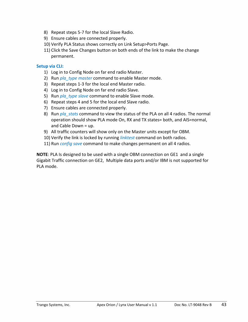
Setup via Web: 1) Login to Web Config Mode on far end Master radio – Link Setup>Ports page. 2) Select PLA Type = Master from the drop down menu. 3) Click the Submit button. 4) Repeat steps 1‐3 for the local Master radio. 5) Login to Web Config Mode on far end Slave radio – Link Setup>Ports page. 6) Select PLA Type = Slave from the drop down menu. 7) Click the Submit button.
Trango Systems, Inc. Apex Orion / Lynx User Manual v 1.1 Doc No. LT‐9048 Rev B 43
8) Repeat steps 5‐7 for the local Slave Radio. 9) Ensure cables are connected properly. 10) Verify PLA Status shows correctly on Link Setup>Ports Page. 11) Click the Save Changes button on both ends of the link to make the change
permanent.
Setup via CLI: 1) Log in to Config Node on far end radio Master. 2) Run pla_type master command to enable Master mode. 3) Repeat steps 1‐3 for the local end Master radio. 4) Log in to Config Node on far end radio Slave. 5) Run pla_type slave command to enable Slave mode. 6) Repeat steps 4 and 5 for the local end Slave radio. 7) Ensure cables are connected properly. 8) Run pla_stats command to view the status of the PLA on all 4 radios. The normal
operation should show PLA mode On, RX and TX states= both, and AIS=normal, and Cable Down = up.
9) All traffic counters will show only on the Master units except for OBM. 10) Verify the link is locked by running linktest command on both radios. 11) Run config save command to make changes permanent on all 4 radios.
NOTE: PLA Is designed to be used with a single OBM connection on GE1 and a single Gigabit Traffic connection on GE2, Multiple data ports and/or IBM is not supported for PLA mode.

Trango Systems, Inc. Apex Orion / Lynx User Manual v 1.1 Doc No. LT‐9048 Rev B 44
XPIC
XPIC allows use of two Orion Radios at the same physical location with the same transmit channel, with each one transmitting on a different polarization. Two coaxial cables (CBLDAT‐XPIC‐4) are connected between the radios on each end of the link to improve the cross polarization performance of each link.
XPIC can be used in conjunction with PLA or as two independent links carrying isolated streams. In either case the spectral efficiency is doubled. Both versions are shown below.
One antenna with a combiner or two antennas at each end of the link are required for XPIC operation. Use of a combiner is shown in the examples below:
Apex Orion 1.5 Gbps XPIC Isolated Streams
– 56/60 MHz Channels
17.9 GHz V Pol
19.46 GHz V Pol
V pol
H Pol
Orion Side AV Pol
Orion Side AH Pol
Orion Side BV Pol
Orion Side BH Pol
Switch/Router Side B
Switch/Router Side A
CBLDAT-XPIC
2x
CBLDAT-XPIC
2x
Antenna
Mgmt+Traffic+POE
Mgmt+Traffic+POE
GE1 GE1
GE1 GE1
Antenna
Mgmt+Traffic+POE
Mgmt+Traffic+POE
750 Mbps
750 Mbps
750 Mbps
750 Mbps
17.9GHz
freq
19.46GHz
17.9 GHz
19.46 GHz
Orthomode Combiner
(OMC)
Orthomode Combiner
(OMC)
XPIC OUTXPIC IN
XPIC OUTXPIC IN
XPIC OUTXPIC IN
XPIC OUTXPIC IN
17.9 GHz H Pol
19.46 GHz H Pol
Figure 13 XPIC Block Diagram

Trango Systems, Inc. Apex Orion / Lynx User Manual v 1.1 Doc No. LT‐9048 Rev B 45
Apex Orion 1 Gbps XPIC with PLA – 56/60 MHz Channels
PLAKIT-9-M 17.9 GHz V Pol
19.46 GHz V Pol
V pol
H Pol
Orion Side AV Pol
MASTER
Orion Side AH Pol
SLAVE
Orion Side BV Pol
MASTER
Orion Side BH Pol
SLAVE
Switch/Router Side B
Switch/Router Side A
CBLDAT-XPIC
2x
CBLDAT-XPIC
2x
Antenna
Traffic+POE Traffic+POE
GE1 GE1
GE1 GE1
Antenna
Mgmt+POE Mgmt+POE
1 Gbps
17.9GHz
freq
19.46GHz
17.9 GHz
19.46 GHz
Orthomode Combiner
(OMC)
Orthomode Combiner
(OMC)
XPIC OUTXPIC IN
XPIC OUTXPIC IN
XPIC OUTXPIC IN
XPIC OUTXPIC IN
17.9 GHz H Pol
19.46 GHz H Pol
PLA
PLA
PLA
PLA
PLAKIT-9-M
1 Gbps
Mgmt GE2 GE2
GE2 GE2
Mgmt
Figure 14 XPIC with PLA Block Diagram
When running XPIC, each link should be aligned and optimized while the other link is off.
Physical spacing between the two radio units co‐located on the same structure can be minimal. For increased resistance to multipath, the units can be separated as much as 10 feet. When using XPIC with PLA, the two radio paths must be of identical length and the cable lengths matched at each end for best performance.
The layer 2 Capacity for XPIC combined with PLA Is shown below in comparison to the absolute maximum line rate. The link operates at full Gigabit rate up to approximately 800 byte packets.

Trango Systems, Inc. Apex Orion / Lynx User Manual v 1.1 Doc No. LT‐9048 Rev B 46
Figure 15 PLA with XPIC Capacity
The setup instructions below cover XPIC only. IF PLA is used with XPIC, set up XPIC first, then set up PLA per the PLA setup instructions.
Setup via Web: 1) Establish each link individually with the other link off and ensure the RSSI and
MSE meet the link specifications. 2) Connect Coaxial Cables per diagram. The “IN” port on each radio must be
connected to the “OUT” port on the other radio for proper operation. 3) Turn both links on and observe the degradation in MSE due to cross polarization. 4) Login to Web Config Mode on one of the far end radios – Advanced
Settings>XPIC page 5) Select XPIC “On” radio button 6) Click the Submit button 7) Repeat steps 4‐6 for the other 3 radios. 8) Verify Link Status is locked for all 4 radios and the MSE and modulation are the
same as when each link was running independently with XPIC off. The MSE should improve when XPIC is enabled.
9) Click the Save Changes button on both ends of the link to make the change permanent.
Setup via CLI: 1) Establish each link individually with the other link off and record the RSSI and
MSE 2) Connect Coaxial Cables per diagram. 3) Turn both links on and observe the degradation in MSE due to cross polarization 4) Log in to Config Node on one of the far end radios. 5) Run xpic_enable on command to enable XPIC mode 6) Repeat steps 4‐5 for the other 3 radios.

Trango Systems, Inc. Apex Orion / Lynx User Manual v 1.1 Doc No. LT‐9048 Rev B 47
7) Run xpic_stats command to check XPIC statistics 10) Verify the link is locked and the MSE is the same as previously when the links
were running independently with XPIC off by running linktest command on all radios. The MSE should improve when XPIC is enabled
11) Run config save command to make changes permanent.

Trango Systems, Inc. Apex Orion / Lynx User Manual v 1.1 Doc No. LT‐9048 Rev B 48
QoS (Quality of Service)
The Orion internal switch performs QoS on all incoming packets to allow the operator to give priority to certain traffic types. The following fields are used to sort the incoming traffic into 8 queues:
- Layer 2 using the COS bits in the VLAN tag on incoming Ethernet traffic (Tagged traffic only).
- Layer 3 Diffserv (DSCP) using the Differentiated services field in IP packets. The DSCP mapping can be controlled on a port by port basis from CLI or Web.
- Port Priority for untagged traffic.
For QoS to work, incoming traffic must be either Tagged with a VLAN with the COS bits set, or an IP packet with the DS bits set. This is done external to the Orion unit using a switch or application to set the priority tag or DS field.
Once the tagged traffic with COS/DSCP priority bits set arrives at the Orion Ethernet port, the internal switch will perform prioritization on the traffic by mapping each packet to one of 8 queues. These 8 queues make up the green packet buffer, which is emptied into a single data pipe going into the modem and packets then transmitted over the air. The size of the buffer is controlled by the green buffer setting.
The scheduling of the queue traffic into the modem data pipe can be Strict Priority (SP) Mode, Weighted Round Robin (WRR) Mode, or a combination of SP and WRR as follows:
1) All Queues Strict 2) All Queues WRR 3) Queues 6 and 7 Strict, Queues 0‐5 WRR 4) Queue 4‐7 Strict, Queues 0‐3 WRR
If no QoS is desired then the user can simply map all priorities to Queue 0. All packets will be treated equally regardless of the other QoS settings with the exception of IEEE1588 packets which are always treated as high priority over all other packets.
All Strict Mode
Strict QoS Mode follows the logic rule below:
Queue 7 > Queue 6 > Queue 5 > Queue 4 > Queue 3 > Queue 2 > Queue 1 > Queue 0

Trango Systems, Inc. Apex Orion / Lynx User Manual v 1.1 Doc No. LT‐9048 Rev B 49
When this mode is selected, the scheduler will empty Queue 7 before sending any Queue 6 packets across the link, and if both Queue 7 and Queue 6 are empty then Queue 5 packets will be sent, etc. Note that while strict priority ensures that ALL high priority traffic will go through (up to max burst size and link capacity limits), it may block lower priority traffic or increase the latency significantly for lower priority packets during traffic congestion.
Weighted Round Robin (WRR) Mode
In WRR QoS Modes, the method of emptying the queues is designed to let at least some of the traffic through for all queues, where the amount is control by weighting of the individual queues. To accomplish this, weights are assigned directly to the Queues. Each weight represents the number of packets that will be transferred out from the queue for each round through the Queues that are included in the WRR algorithm. Queue 0 Weight = 1 Queue 1 Weight = 3 Queue 2 Weight = 6 Queue 3 Weight = 9 Queue 4 Weight = 12 Queue 5 Weight = 15 Queue 6 Weight = 18 Queue 7 Weight = 21
When Strict mode is used the weights are ignored.
Higher weights translate to proportionally more throughput than lower weights. In the default configuration, most or all of the traffic will pass for Queue 7 but some will still pass for Queue 0. The behavior is the same for VLAN tagged traffic or Diffserv traffic. For Diffserv, the DSCP field in the IP packet will contain a number from 0‐63 in the Type of Service (TOS) field, which can be mapped to a priority level, which is subsequently mapped to a queue.
Queue 7 through 4 Strict, Queues 0 through 3 WRR
When this mode is selected, the scheduler will treat Queues7 through 4 with the strict algorithm, and if any bandwidth is remaining after all Queues 7 through 4 are empty, the WRR algorithm will be used to move packets from Queues 0 through 3.
In this mode only weights for Queues 0 through 3 apply ‐ the weights for Queues 4 through 7 do not apply since these queues are in strict mode.
Queue 7 and 6 Strict, Queues 0 through 5 WRR

Trango Systems, Inc. Apex Orion / Lynx User Manual v 1.1 Doc No. LT‐9048 Rev B 50
When this mode is selected, the scheduler will treat Queues7 and 6 with the strict algorithm, and if any bandwidth is remaining after all Queues 7 and 6 are empty, the WRR algorithm will be used to move packets from Queues 0 through 5.
In this mode only weights for Queues 0 through 5 apply ‐ the weights for Queues 6 and 7 do not apply since these queues are in strict mode.
Mapping VLAN tag COS bits to a Queue
The default priority mapping is as follows: COS priority 0 Queue 0, Lowest Priority Queue COS priority 1 Queue 1 COS priority 2 Queue 2 COS priority 3 Queue 3 COS priority 4 Queue 4 COS priority 5 Queue 5 COS priority 6 Queue 6 COS priority 7 Queue 7, Highest Priority Queue These default mappings can be changed with the qos command, allowing the packets to be mapped into any one of the 4 queues based on the COS bit in the VLAN tag. Different priority tags may be mapped into the same queue if desired. For DSCP tagged traffic, the DSCP field can be mapped to one of the 7 priorities which is in turn mapped to one of the 7 queues.
Mapping Diffserv Traffic to a Queue
For Layer 3 IP packets, traffic with marked traffic Differentiated Services (DS) fields can be prioritized by the internal switch. DSCP Code Points (0‐63) are mapped to a Priority Level (0‐7), which is in turn mapped to a Queue
For Diffserv, the default mappings for all ports are as follows: DSCP 1 to 9 Priority 0 Queue 0 DSCP 10 to 19 Priority 1 Queue 1 DSCP 20 to 29 Priority 2 Queue 2 DSCP 30 to 39 Priority 3 Queue 3 DSCP 40 to 45 Priority 4 Queue 4 DSCP 46 to 49 Priority 5 Queue 5 DSCP 50 to 55 Priority 6 Queue 6 DSCP 56 to 63 Priority 7 Queue 7
DSCP must be enabled to enforce QoS using DSCP.

Trango Systems, Inc. Apex Orion / Lynx User Manual v 1.1 Doc No. LT‐9048 Rev B 51
Setup via Web: 1) Login to Web Config Mode ‐ Link Setup>QOS page on far side radio. 2) Select All Strict , All WRR, Strict Q6/Q7, or Strict Q4‐7mode from the drop down
menu. 3) If remapping of L2 VLAN Priority field is desired, change the Queue numbers
assigned to the PRI values. Queue 7 is always emptied first for strict mode, then Queue 6,5, and 4, etc..
4) If WRR, Strict Q6/Q7, or Strict Q4‐7mode is selected and weights need to be changed from default, enter the new weights in the box (range = 1 to 49).
5) For Diffserv to Priority mappings, adjust the mappings for each code point used by selecting the Priority from the drop down menu.
6) Click on the submit button after all changes are made. 7) Repeat steps 1‐5 for the near side radio if desired. 8) Verify traffic passes as expected. 9) Click the Save Changes button on both ends of the link to make the change
permanent.
Setup via CLI: 1) Log in to Config Node on the far end radio. 2) Run qos mode<0‐3> command to select mode (default is 2‐ Q4/7 Strict). 3) If remapping of L2 VLAN Priority field is desired, change the queue numbers
assigned to the PRI fields by running the qos_cos_que <pri> <queue> command. Queue 7 is always emptied first for strict mode, then Queue 6, 5, and 4, etc.
4) If WRR mode is selected and weights need to be changed from default, enter the new weights (range=1 to 49) using the qos weight <queue> <weight> command.
5) For Diffserv to Priority/Queue mappings, run the qos dscp_source <DSCP> <pri> command for each DSCP code point that will be used.
6) Repeat steps 1‐5 for the near side radio if desired. 7) Verify traffic passes as expected. 8) Run config save command to make changes permanent on both radios.

Trango Systems, Inc. Apex Orion / Lynx User Manual v 1.1 Doc No. LT‐9048 Rev B 52
Opmode (Transmitter On/Off Control)
User can turn the transmitter on and off with the opmode command. If a reboot to the radio occurs, the transmitter will automatically turn back on if the opmode was on during the last config save. During TX frequency changes, the transmitter will be briefly turned off before setting the new frequency to prevent spectral splatter to adjacent channels.
Setup via Web: 1) Login to Web Config Mode ‐ Link Setup>Link page on radio. 2) Click on the Transmitter On or Off radio button. 3) Click Submit button to make the change‐ Note that if either transmitter is turned
off the link will be broken and connectivity may be lost. 4) Verify desired result. 5) Click Save Changes button to make change permanent.
Setup via CLI:
1) Log in to Config Node on the radio. 2) Run opmode <on|off> command to turn transmitter on or off. 3) Verify desired result. 4) Run config save command to make changes permanent.
Rapid Port Shutdown (RPS)
To support external switches using Spanning Tree or facilitate faster routing convergence after topology changes, the physical ports can be configured to shutdown simultaneously on both ends of the link upon user selectable events on either end of the link. The traffic ports on both ends of the link will be shut down for 30 seconds to allow L2/L3 tree protocols to reroute traffic. After the 30 seconds expires, the ports will be re‐enabled to allow management of the radios. RPS is selected as a threshold action, tied to any one of the following events:
1) RSSI out of range 2) MSE out of range 3) BER exceeds MAX value 4) System Temperature out of range 5) In port Utilization exceeds MAX value 6) Out Port Utilization MAX value 7) Link Down
It is highly recommended that the operator enable ACM when using RPS since the fade margin will be much higher than a non‐ACM speed setting, preventing link loss and subsequent rerouting during weather related events.

Trango Systems, Inc. Apex Orion / Lynx User Manual v 1.1 Doc No. LT‐9048 Rev B 53
Setup via Web: 1) Login to Web Config Mode ‐ Advanced Setting>Threshold page on radio. 2) Review the threshold settings and change if necessary. 3) Click on the RPS check box for the events that RPS should trigger on. 4) Click Submit button to make the change. 5) Click Save Changes button to make change permanent.
Setup via CLI:
1) Log in to Config Node on the radio. 2) Run threshold action 8 2 command to enable RPS for Link loss. Other options
are available for to activate RPS. – See the CLI Guide for more info. 3) Verify desired result. 4) Run config save command to make changes permanent.
Threshold Settings
The user can set actions to occur upon threshold violations for critical link parameters.
The following thresholds can be configured: 1) RSSI 2) MSE 3) BER 4) ODU Temp 5) In Port utilization 6) Out port Utilization 7) Link Down
The following actions can be configured as a result of a threshold violation: 1) No action 2) SNMP Trap 3) Rapid Port Shutdown on local dataport.
Setup via Web: 1) Login to Web Config Mode ‐ Advanced Setting>Threshold page on radio. 2) Review the threshold settings and change if necessary. 3) Click on the “trap” and/or “RPS” action check box for the events that should
trigger any action. 4) Click Submit button to make the change.
If “trap” was selected as an action, Login to Web Config Mode ‐ Advanced Setting>SNMP page on radio. If trap was not selected as an action then proceed to Step 8.
5) Enter at least one IP address for the SNMP Trap Manager that will receive the traps.
6) Click the “enable” radio button for each SNMP manager.

Trango Systems, Inc. Apex Orion / Lynx User Manual v 1.1 Doc No. LT‐9048 Rev B 54
7) Click Click Submit button to make the changes. 8) Click Save Changes button to make change permanent .
Setup via CLI:
1) Log in to Config Node on the radio. 2) Run threshold action <0‐8> <0‐2> command to set an action for the events that
should trigger any action. (see CLI guide for detail) 3) If “trap” was selected as an action, run the trap ip <1‐5> <IP address> command
to set the SNMP Trap Manager IP address. Up to 5 trap managers can be set up. 4) If trap was not selected as an action then proceed to Step 6. 5) Run the trap enable <1‐5> command to activate the individual trap IP address. 6) Run config save command to make changes permanent.
Port Rate Limiting (Ingress)
The port rate limiting feature is used to restrict the ingress traffic rate on a specific Ethernet port. This is useful for Service Level Agreements (SLAs) to end users.
For example, if the Ethernet port line rate is 1000BaseT, and the RF channel capacity is 500 Mbps, setting GE1 max rate to 125 Mbps will prevent any more than 125 Mbps of traffic from being forwarded to the modem port.
Setup via Web: 1) Login to Web Config Mode ‐ Link Setup>Ports page on radio. 2) Modify the Max Rate box to set the maximum ingress bit rate of the selected
port. 3) Click Submit button to make the changes. 4) Click Save Changes button to make change permanent
Setup via CLI:
1) Log in to Config Node on the radio. 2) Run port eth <1‐2> maxrate <max rate in mbps> command to set the maximum
ingress bit rate for the selected port. 3) Run config save command to make changes permanent.
Note: The procedure must be done on both radios to limit traffic both directions
Status Snapshot
Upon successful configuration of the link, the user can save all critical parameters of the link such as RSSI, MSE, TX power, siglevel diagnostics, and system information to be recalled at a later date and compared to current conditions. This feature is a useful troubleshooting tool to isolate changes to a link that may affect performance over time.

Trango Systems, Inc. Apex Orion / Lynx User Manual v 1.1 Doc No. LT‐9048 Rev B 55
Setup via Web: 1) Login to Web Config Mode ‐ Diagnostics>Status Display page on radio. 2) Click on the Status Save Button at the bottom of the page to save the current
state of the radio to FLASH. 3) At a later date, to compare the current state of the radio to the state of the radio
when the status save button was clicked, click the submit button at the top of the Status Display page.
4) View the comparison of the each parameter and note changes. 5) Click the Screen Clear button if desired.
Setup via CLI:
1) Log in to Config Node on the radio. 2) Run status save command to set the maximum ingress bit rate for the selected
port. 3) At a later date, run status compare command to compare the current state of
the radio to the state of the radio when the status save command was last run. 4) View the comparison of the each parameter and note changes.
Management Services
The user can enable or disable the Telnet, TFTP, HTTP, and SNMP daemons to restrict access to the radio unit.
Default Settings Telnet enabled TFTP disabled HTTP enabled SNMP enabled
Setup via Web 1) No changes to the services are allowed via the web.
Setup via CLI:
1) Log in to Config Node on the radio. 2) Run tftpd <on|off> command to enable/disable the TFTP server. 3) Run telnetd <on|off> command to enable/disable the telnet server. 4) Run httpd <on|off> command to enable/disable the web server. 5) Run snmpd <on|off> command to enable/disable the SNMP server. If disabled,
the Web interface will also be lost since the Web server uses SNMP OIDs to retrieve information.
6) Run config save command to make changes permanent.

Trango Systems, Inc. Apex Orion / Lynx User Manual v 1.1 Doc No. LT‐9048 Rev B 56
Firmware Update
Remote update of the system firmware is available via TFTP or FTP. The TFTP daemon must be enabled if TFTP is used to update the system.
bootimage upgrade – upgrades the flash memory with the new software following TFTP or FTP of new firmware into the system. A system reboot is required after performing this command to load the new firmware
Before beginning the update procedure, be certain that all required files have been downloaded to an easily accessible directory on your local hard drive.

Trango Systems, Inc. Apex Orion / Lynx User Manual v 1.1 Doc No. LT‐9048 Rev B 57
Upgrade Procedure ‐TFTP
!
ALWAYS CONSULT THE UPGRADE INSTRUCTIONS THAT ARE INCLUDED WITH A NEW FIRMWARE RELEASE AS CERTAIN FILES MAY NOT BE REQUIRED FOR AN UPGRADE.
1) Place the firmware files in an easily accessible directory path on your computer.
2) Telnet into the radio. The figures use the default IP address; you must use the correct IP address for the Apex Orion.
3) At the login enter your username and password. The username is “admin “and default password is “trango”
4) Enter config node by typing “config” and entering the write access password. The default config node password is “trango”
5) Enable the tftp daemon by running the tftpd on command at the prompt.
6) Open a MS‐DOS prompt (or other CLI interface) window and access the directory that you extracted the firmware files.
C:\CD Firmware C:\Firmware
7) Using windows TFTP command line tool, we will upload the firmware file. The tftp syntax and an example are below.
Note that TFTP is not installed automatically on all versions of Windows. It mey need to be installed or a third party program such as tftpd32.
TFTP [‐i] host [GET | PUT] source [destination]
C:\firmware>tftp ‐i 192.168.100.100 put sl24v101.tar.gz Transfer successful: 1951744 bytes in 15 seconds, 130116 bytes/s
8) Once the file has been transferred successfully, log back into the unit and apply the updates into the FLASH memory using the bootimage upgrade command from the config mode. Do not unplug the radio during the time the flash is being updated or the FLASH may become corrupted.

Trango Systems, Inc. Apex Orion / Lynx User Manual v 1.1 Doc No. LT‐9048 Rev B 58
9) A reboot of the radio is required to load the new image after upgrade using the reboot command. Make sure the bootimage upgrade command completed successfully before rebooting or repowering the unit.
The upgrade time varies depending upon the images and the size of the image.
The firmware can be verified by logging into the radio via the CLI through the version command or Web browser version page under the Firmware Version section.
The Current firmware is the currently running firmware. The firmware which was replaced will be listed under the Previous Images heading.

Trango Systems, Inc. Apex Orion / Lynx User Manual v 1.1 Doc No. LT‐9048 Rev B 59
Upgrade Procedure ‐FTP
To perform the firmware upgrade using FTP, use the ftp command to load the images into memory, then the bootimage upgrade commands just as with the TFTP method. The FTP method is much faster and has built in error checking.
All that is needed is the IP address of the ftp server, a username/password, and the filename to be uploaded. The new file to be uploaded should be placed on the server. The ftp server will prompt for the password before allowing access.
1) Put the new software files on the ftp server using the ftp put command from a local computer (these commands are not done from the Trango equipment).
ftp> put <source file> <destination>:
The <source file> will be the filename only. The <destination> will include both path and file name.
2) After putting the file onto the server, log into the Apex Orion and run the ftp command from the command line as follows to open access to the server:
ftp <server_ip> <user_name>
password: xxxxxxx
If prompted for the password multiple times, check the connectivity to the server by pinging the FTP server IP address from the debug prompt.
3) Next , get the file from the FTP server by typing the get command from the ftp prompt.
ftp> get <file_name>
4) Logout of the ftp session
ftp> logout
5) Run the bootimage upgrade command.
IP Configuration
The user can set one IP address and subnet mask to be used for both out of band (OBM) and in‐band management (IBM). Only valid IP addresses are accepted. The IP address can be reset to the default setting of 192.168.100.100 via an external button on the unit or a separate command.

Trango Systems, Inc. Apex Orion / Lynx User Manual v 1.1 Doc No. LT‐9048 Rev B 60
IBM can be done through any Ethernet port with or without a specific VLAN assigned. The QoS features will allow prioritization of management traffic to prevent loss of connectivity during traffic overload conditions when a VLAN with high priority tag is used to manage the link.
The default gateway is configurable
Default Setting IP address: 192.168.100.100 IBM enable on Management port GE1 (RJ45) IBM Tagging off
Setup via Web: 1) Login to Web Config Mode ‐ Link Setup>Link page on radio. 2) Enter the desired IP address in the text box. 3) Enter the desired Netmask in the text box. 4) Enter the desired Gateway in the text box. 5) Click Submit button to make the change ‐ Note that connectivity will be lost until
connecting using the new IP address.
Setup via CLI: 1) Log in to Config Node on the radio. 2) Run ipconfig gateway <gateway ip adress> command to change the gateway
address. 3) Run ipconfig ip <ip address> <netmask> command to change the IP address and
netmask. ‐ Note that connectivity will be lost until connecting using the new IP address.
4) No save is required.
GPS Coordinates
Allows entering/saving the GPS Coordinates manually to assist in plotting the endpoints of each link on third party management software link SNMP managers and Google Earth/Maps.
Setup via Web: 1) Login to Web Config Mode ‐ Link Setup>Link page on radio 2) Enter the desired Latitude in the text box. The default format is X 00 00.00
where X is N or S. Other formats may be used since this is a text field. 3) Enter the desired Longitude in the text box. The default format is Y 00 00.00
where Y is E or W. Other formats may be used since this is a text field. 4) Click Submit button to make the change. 5) Click the Save Changes button to make the change permanent.

Trango Systems, Inc. Apex Orion / Lynx User Manual v 1.1 Doc No. LT‐9048 Rev B 61
Setup via CLI:
1) Log in to Config Node on the radio. 2) Run gps_lat <Latitude> command to change the latitude. The default format is X
00 00.00 where X is N or S. Other formats may be used since this is a text field. 3) Run gps_long <Longitude> command to change the longitude. The default
format is Y 00 00.00 where Y is E or W. Other formats may be used since this is a text field.
4) Run config save command to make changes permanent.
Ethernet Port Settings
The input Ethernet ports can be configured independently to match the network. The default settings are recommended for most situations and no changes need to be made. No modification of the PLA port is allowed since it is dedicated for use between two radio units only. The following parameters can be modified:
1) The Ethernet ports GE1 and GE2 can be configured to be autonegotiate or fixed.
2) The GE1 and GE2 ports can be disabled.
3) The speed can be changed if Autonegotiate is disabled, however, note that the SFP ports are a fixed Gigabit and cannot be set to lower physical speeds.
4) Port priority can be assigned to place untagged traffic into one of the QoS Queues.
5) The ingress rate can be limited if desired using the port eth <1|2> maxrate command.
6) Pause frames can be enabled on the port for traffic flow when connected at Gigabit speeds.
Default Settings for GE1 and GE2 Port Enable= On Autonegotiate=On Priority = 0 Max Rate = 1000
Setup via Web: 1) Login to Web Config Mode ‐ Link Setup>Ports page on radio. 2) To disable Autonegotiate, select Disable from the “Auto Nego” drop down menu,
then select the Submit button. The Duplex and Speed drop down boxes will become available.

Trango Systems, Inc. Apex Orion / Lynx User Manual v 1.1 Doc No. LT‐9048 Rev B 62
3) To disable a port, select Disable from the “Enable” drop down menu, then select the Submit button. Disabling may result in a lost connection to the radio unit.
4) Select the Speed desired from the drop down boxes, then click the Submit button to activate. (Autonegotiate must be off).
5) To change the Max rate, enter the rate in Mbps into the text box and click the Submit button to activate.
6) To change Port Priority, select the Priority level from the drop down and click the Submit button to activate.
7) Click the Save Changes button to make the change permanent.
Setup via CLI: 1) Log in to Config Node on the radio. 2) Run port eth <1|2> auto_negotiate <on|off> command to enable or disable
autonegotiation for the port. 3) Run port eth <1|2> enable <on|off > command to enable or disable the port.
Disabling may result in a lost connection to the radio unit. 4) Run port eth <1|2> speed <100|1000> command to force the link speed – Full
duplex modes are supported only. Autonegotiate must be off prior to forcing the speed of the port.
5) Run port eth <1|2> maxrate <0‐1000> command to limit the ingress rate on the port selected.
6) Run port eth <1|2> pause <on|off> command to enable disable the pause feature for the port selected.
7) Run port eth <1|2> priority <0‐7> command to enable prioritization of untagged traffic on the port selected.
8) Verify the desired results. 9) Run config save command to make changes permanent.

Trango Systems, Inc. Apex Orion / Lynx User Manual v 1.1 Doc No. LT‐9048 Rev B 63
Link Planning This section describes the process that occurs before installing and setting up an Apex Orion system.
Path Planning
In most countries, the Apex Orion requires a regulatory body license to be operated. Licenses typically specify the Transmit and Receive Frequencies, Channel bandwidth and modulation, Transmitter Power level and Antenna Gain for a specific site location and height. It is up to the purchaser to ensure that all local regulations have been met before operating the Apex Orion to avoid interfering with existing installed equipment. In the US, path coordination is done to ensure that new installations do not interfere with existing links.
To ensure success, a path analysis should be done for each link that is being considered. Antenna heights, system gain, rain region and terrain data are evaluated to determine the reliability of the link over time and changing weather.
Trango will run path analysis for its customers using industry standard software, evaluate different equipment options to achieve the customer goals.
Spreadsheet, Smart phone, and tablet based link planning tools are also available from Trango for basic analysis of potential paths.
Site Selection
After the Planning phase is complete, it is essential that the proposed site be physically evaluated by the operator to ensure that no buildings or vegetation has crossed into the Fresnel zone that would affect operational reliability.
It is not uncommon for tall buildings to be located in what would otherwise be a perfect non blocked line of sight path based on terrain data, but too often this is discovered when the installation is being performed.
The site must also be evaluated for power and shelter provisions.
Contact Trango for more information on the above topics.

Trango Systems, Inc. Apex Orion / Lynx User Manual v 1.1 Doc No. LT‐9048 Rev B 64
Installation This section describes the installation to ensure that the Apex Orion radio units are correctly installed. Failure to follow these procedures may result in damage to the equipment and void the factory warranty.
Safety Installing microwave equipment can be dangerous. Please take the following precautions when installing or performing maintenance on the equipment. Equipment Protrusions: The equipment has been designed to be free of unnecessary protrusions or sharp surfaces that may catch or otherwise cause injury during handling. However, always take care when working on or around the equipment. Laser and Fiber Optic Cable Hazards: Trango fiber optic SFP Module transmitters are IEC60825‐1 / 21CFR1040‐1 Class I compliant and present no danger to personnel in normal use. However: Do not look into active un‐terminated optical ports or fibers. If visual inspection is required ensure the equipment is turned off or, if a fiber cable, disconnect the far end. Follow the manufacturer's instructions when using an optical test set. Incorrect calibration or control settings could result in hazardous levels of radiation. Protect/cover unconnected optical fiber connectors with dust caps. Place all optical fiber cuttings in a suitable container for safe disposal. Bare fibers and fiber scraps can easily penetrate the skin and eyes. Lifting Equipment: Be careful when hoisting or lifting the ODU or its antenna during installation or maintenance. The Apex Orion unit is nominally 10 lbs. However, antennas with their mounting hardware can weigh in excess of 100 kg (220 lb) and require specialized lifting equipment and an operator trained and certified in its use. Protection from RF Burns: Apex Orion radios do not generate RF fields intense enough to cause RF burns, however, installers/operators should comply with the following cautions:
1) It is hazardous to look into or stand in front of an active antenna aperture. Do not stand in front of or look into an antenna without first ensuring the associated transmitter or transmitters are switched off.
2) Do not look into the waveguide port of an ODU when the radio is active.
Protection from RF Burns ‐ Tower Site: When the Apex Orion radio unit is to be installed where existing antennas are located, avoid exposure to potentially harmful levels of RF radiation from these antennas by:

Trango Systems, Inc. Apex Orion / Lynx User Manual v 1.1 Doc No. LT‐9048 Rev B 65
1) Determining the RF exposure risk. If necessary ask the structure/tower owner or operator. When necessary, wear a protective suit or have the transmitter(s) switched off for the duration of the installation.
2) Do not stand in front of or look into any antennas.
Safety Warnings: When a practice or procedure poses implied or potential harm to the user or to the radio equipment, a warning is included in this manual. Airflow Requirements: Installations must be made so the airflow required for safe and correct operation of Trango equipment is not compromised. For the Apex Orion, unobstructed air flow must be maintained to all sides of the unit. Circuit Overloading: When connecting the Apex Orion, determine the effect this will have on the power supply, circuit protection devices, and supply wiring. Check Apex Orion power consumption specifications and the supply capability of the power supply system. This check of capacity must extend to the dc power supply and not just to an intermediate connection point. Power Supply Earthing: ‐48 V power supply earth must be connected directly to a bonding jumper from an earthing terminal bar or bus. Electrostatic Discharge (ESD): ESD can damage electronic components. Even if components remain functional, ESD can cause latent damage and/or premature failure. Always wear proper ESD grounding straps when handling or touching any PCB assemblies. Connect your ESD grounding strap to the ground connector on the ODU or PoE units as applicable Fiber Optic Cables: Handle optical fibers with care. Keep them in a safe and secure location during installation. Do not attempt to bend them beyond their minimum bend radius. Protect/cover unconnected optical fiber connectors with dust caps. Ground Connections: Reliable grounding of the system must be maintained. Refer to instructions in this manual for grounding of the ODU, ODU cable, lightning surge suppressor, and IDU. Lightning Surge Suppressor: Apex Orion Ethernet cables should be fitted with surge suppressors to prevent damage to equipment. Contact Trango for further details. Mains Power Supply Routing: Apex Orion DC power, Ethernet data and management cables are not to be routed with any AC mains power lines. They are also to be kept away from any power lines which cross them.

Trango Systems, Inc. Apex Orion / Lynx User Manual v 1.1 Doc No. LT‐9048 Rev B 66
Ambient Temperature: The ambient temperature range for the Apex Orion is ‐40° to +55° Celsius. To ensure operation and to maximize long term component reliability, ambient temperatures must not be exceeded. Operational specification compliance is not guaranteed for temperatures outside this range. Mechanical Loading: When installing the Apex Orion unit and antenna/remote mount on a tower mount or building, ensure the mount is securely anchored first and can support the full load of the radio unit and antenna. Ensure that the additional loading of an Apex Orion unit will not cause any reduction in the mechanical stability of the mount. Power Supply Connection: The Apex Orion radio has the positive pin on its dc power supply connector connected directly to the chassis, which is in turn connected directly to the earth ground through the tower leg. Apex Orion radios must be used with a ‐48 Volt DC power supply which has a positive earth; the power supply earth conductor is the positive supply to the radio or PoE injector.
1) There must be no switching or disconnecting devices in this earth conductor between the dc power supply and the point of connection to an Apex Orion system.
2) The power supply must be located in the same premises as the Apex Orion system.
3) All Ethernet cabling which is carrying power to the Apex Orion radio unit from the PoE injector must be 24 AWG solid strand Cat 5e or Cat 6 Shielded Twisted Pair (STP) cable with all 8 conductors terminated using shielded connectors with a solid connection made between the cable and connector ground.
Power Supply Disconnect: An appropriate power supply disconnect device should be provided as part of the building installation. Rack Mount Temperature Considerations: If the Apex Orion PoE unit is installed in a closed or multi‐unit rack assembly, the operating ambient temperature of the rack environment may be greater than room ambient. The maximum ambient temperature of +55°Celsius applies to the immediate operating environment surrounding the PoE unit, which, if installed in a rack, is the ambient within the rack. Restricted Access: The Apex Orion system should be installed in restricted access sites. The PoE unit and associated power supply should also be installed in restricted areas, such as dedicated equipment rooms, closets, cabinets, or the like. Access to the tower and radio/antenna location should be restricted. Note: For USA: In restricted access areas install the Apex Orion system in accordance with articles 110‐26 and 110‐27 of the 2002 National Electrical Code ANSI/NFPA 70.

Trango Systems, Inc. Apex Orion / Lynx User Manual v 1.1 Doc No. LT‐9048 Rev B 67
Basic Link Setup The Apex Orion comes preconfigured to link up as soon as power is applied. It is highly recommended that the link be bench tested first before field installation. The section below covers the basics steps for setting up the link. Detailed information on field installation is in the Detailed Field Installation Section. BENCH TEST:
1) Apply power using the PoE or with direct power (‐48VDC). 2) Log into each unit using a browser, SSH or telnet ,with the default IP addresses of
192.168.100.100 with the following user/passwords: a. View node user: admin password: trango b. Config node: user: config password: trango
3) Units should link if waveguide ports are oriented toward each other. 4) Adjust the transmit power as appropriate per the regulatory license obtained. 5) Save changes. 6) Change the IP address to the desired IP address and submit. Radio connection
will be lost until new IP address is used. FIELD INSTALL:
1) Install the antennas onto the mounting pole at each end of the link and visually align them toward each other.
2) Latch one Apex Orion unit to the back of the antenna with “V” indicator at the top ‐ This unit will be transmitting and receiving Vertical Polarization.
3) Latch the other Apex Orion unit to the far end antenna with the “V” indicator at the top – This unit will also be transmitting and receiving Vertical Polarization.
4) Power up the radios using PoE or with direct power (‐48VDC) 5) Align the radios using the BNC RSSI output to obtain the expected RSL. 6) The Link LED, located near the direct power input connector, should light up
solid green on both ends.

Trango Systems, Inc. Apex Orion / Lynx User Manual v 1.1 Doc No. LT‐9048 Rev B 68
Detailed Field Installation The standard procedure for installing the equipment in the field is as follows:
1) Antenna Installation
2) Power Supply and PoE (optional) Installation
3) Run Ethernet and Power Cable
4) Install radio onto antenna at both ends and connect cables
5) Antenna Alignment
6) Proceed to commissioning.
CAUTION: Apex Orion has no user serviceable parts. Only factory certified personnel should make any changes or repairs to the units.
The following tools are required for installation: Adjustable Open Ended Wrench Ethernet cable crimp tool #2 Flat screwdriver #2 Philips Head screwdriver Stranded 18 AWG wire for power connection Stranded 12 AWG wire for Apex Orion ground connections Wire Insulation strippers for ground and power wire Terminal crimpers for ground and power wire

Trango Systems, Inc. Apex Orion / Lynx User Manual v 1.1 Doc No. LT‐9048 Rev B 69
Antenna Installation
Antennas are typically installed and are coarse aligned without the radio either visually or with third party equipment. Alternatively, some operators prefer to install the radio equipment onto the antenna prior to installing the antenna on the rooftop or tower.
Apex Orion provides a very accurate voltage that represents the RSSI actually being received by the radio unit and it is highly recommended that the installer use this voltage to align the antennas.
Consult the antenna manual for detailed installation instructions.
Power Supply and PoE Installation
The Apex Orion requires a ‐48 Volt power supply. Trango recommends the ‐48 VDC universal wall mount power supply, 1.6 A (part# P‐SUPPLY‐WMP‐48‐L). This power supply can support one Apex Orion unit with either a directly or via PoE. The power supply should be mounted in a weather protected location close to the main ground. See the Cabling/Grounding Diagram for more information.
Figure 16 Wall Mount Power Supply
Each unit is supplied with a locking two position terminal block that plugs into the Apex Orion main access panel or into the PoE Injector. The wiring of the pluggable terminal block is shown below.
The cabling used should be either coaxial (shown) or two wires of a size no smaller than 18 AWG. If individual wires are used, the wires should be twisted together to reduce susceptibility to noise. At least one turn per inch is recommended.

Trango Systems, Inc. Apex Orion / Lynx User Manual v 1.1 Doc No. LT‐9048 Rev B 70
NOTE: Ensure that only a ‐48 Volt Supply is used and that the wiring is correct. If a +48 VDC supply is used and the Earth ground is wired to the negative terminal shown in the figure, permanent damage to the unit may occur.
Figure 17 ‐48 VDC Power Connector using coaxial cable
In the figures above, the Power can be connected in two ways, Power‐over‐Ethernet or Direct DC Power as described in the sections below.
Running Cable
Running the cables depends on the type of installation. In most cases PoE based installation is used, but the power can be directly connected to the unit as a backup or in the case of running long lengths of fiber to the radio unit.
PoE Based Installation
This section covers installation when powering the unit through Power Over Ethernet (PoE) using a single Cat5e or Cat6 Shielded Twisted Pair (STP) Cable used for management and user traffic. The POE‐GIGE‐48 is shown in the Figure below:
Figure 18 POE‐GIGE‐48

Trango Systems, Inc. Apex Orion / Lynx User Manual v 1.1 Doc No. LT‐9048 Rev B 71
The PoE Power Injector (POE‐GIGE‐48) should be connected to the built in copper Ethernet port only. Either crossover or straight through cable can be used depending on the connection:
1. Connecting to a Computer: Always use a shielded Cross‐Over Ethernet cable when connecting the out‐of‐band Management Port to a COMPUTER
2. Connecting to another Network Device: Always use a shielded Straight‐Through cable when connecting the Data Port to a HUB, SWITCH, or ROUTER
IMPORTANT INFORMATION ON PoE
1) The PoE is non‐standard and will not support 802.3af due to the high current requirements of the radio unit.
2) The total length of the Ethernet cabling from network switch to Apex Orion unit cannot exceed approximately 75 meters or 250 feet or CRC errors may be encountered at the radio input. This length is the sum of the length of cable from the PoE injector to the Apex Orion unit + the length of cable from the PoE Injector to the network switch.
3) Since the PoE Requires ALL 8 conductors AND the shield which acts as the ground, it is critical that:
a. ONLY shielded Twisted Pair (STP) Cat5e or Cat6 cabling be used.
b. Shielded connectors are used with the shield crimped properly to the cable shield wire, or preferably soldered.
c. All 8 conductors are wired.
If any of the above conditions are not met the PoE function may not work correctly!
The wiring for basic PoE installation using the POE‐GIGE‐48 is shown below. The powered cable must only be connected to the built in RJ45 connector on the radio.
Do not connect ANY cables from the PoE‐GIGE‐48 to any SFP module on the radio or the SFP module will be damaged.
The Management side of the POE‐GIGE‐48 is not used for Apex Orion.

Trango Systems, Inc. Apex Orion / Lynx User Manual v 1.1 Doc No. LT‐9048 Rev B 72
TO O
DU
DATA PO
RT
TO O
DU
MA
NA
GE
MEN
T POR
T
MG
MT P
OR
T FUSE
DA
TA PO
RT FU
SE
OD
U O
N
OD
U O
FFG
ND
-48V
GN
D-48V
Figure 19 PoE Wiring

Trango Systems, Inc. Apex Orion / Lynx User Manual v 1.1 Doc No. LT‐9048 Rev B 73
Direct Power Based Installation
This section covers installation when powering the unit through the direct ‐48 Volt DC port and using the Copper or Fiber traffic interfaces is desired.
The primary benefit of direct power is that no surge suppression is required on the traffic interface since it is fiber and the distance to the network can be longer due to the long lengths supported by the fiber and direct power wiring. The 100 meter limitation still applies for any copper Ethernet cabling.
For long runs of Power, coaxial cable is recommended in conjunction with surge suppressors to reduce the risk of voltage spikes causing damage to network equipment.
The Direct Power Input on the front panel is shown below. The pre‐ assembled terminal block plug should be attached until the plug snaps into place.
Figure 20 Direct Power Connector

Trango Systems, Inc. Apex Orion / Lynx User Manual v 1.1 Doc No. LT‐9048 Rev B 74
Cable/Grounding Diagram
The diagram below shows the cable wiring for PoE based installations. Grounding of Ethernet cable should be done at the base of the tower using the Terminal Block on the PoE Injector/Surge Suppressor Box. This applies to direct power or PoE powered installations using copper Ethernet. The surge suppression built into the PoE‐ GigE‐48 will help protect network equipment inside the shelter from damage.
A Ground wire of AWG 12 or larger should be used and grounded to an Earth grounded tower leg or Bus Bar before entry into the shelter. The figure below shows the overall ground design.
Figure 21 PoE Based Cable/Grounding Diagram

Trango Systems, Inc. Apex Orion / Lynx User Manual v 1.1 Doc No. LT‐9048 Rev B 75

Trango Systems, Inc. Apex Orion / Lynx User Manual v 1.1 Doc No. LT‐9048 Rev B 76
Radio Installation onto Antenna
After the cables have been run the Apex Orion radio can be installed. The Apex utilizes a slip fit connection that makes installation simple. The radios are designed to mount to the ADxG‐xx‐xx series of antennas.
Figure 22 Antenna to Radio Slip Fit Waveguide connection
After installing and securing the antenna the Apex Orion unit can be installed directly on the back of the antenna.
For 6 GHz models, the “V” indicator must always be located next to the V marking on the antenna since this model uses a rectangular waveguide. The waveguides must match for proper operation.
For 7‐40 GHz, on both ends of the Link the “V” indicator on the unit must be at the top If vertical polarization is to be used. If horizontal polarization is to be used, install both radios with the “H” indicator located at the top. These rules apply to radios mounted directly to the antenna only. If combiners are used, consult the Combiner manual for instructions on the correct polarity to use.
Polarization Indicators – The letters “H” and “V” are die cast on the Apex Orion housing perimeter to assist in mounting the unit to the antenna in the correct polarization. The letter that is at the top will always indicate the antenna polarization used for transmit.
Antenna O‐Ring Seal
StrataLink WaveguideAntenna
Waveguide port

Trango Systems, Inc. Apex Orion / Lynx User Manual v 1.1 Doc No. LT‐9048 Rev B 77
Figure 23 Polarization Indicator
Cover the antenna O‐ring with silicone grease per the Antenna manual. Failure to do this may result in a damaged O‐ring and subsequent damage to the antenna or radio.
Gently slide the Apex Orion unit onto the antenna and clip the four spring loaded latches to the antenna clips as shown below. To ease installation, attach opposite corners first. The latches should be very snug and “click” into place. If there is difficulty closing the latches, then check the waveguide for debris or foreign matter around the perimeter.
Secure the latches eyelets with locks if desired.
Figure 24 Mounting Latches
“V” polarization indicator
Latch with Eyelet

Trango Systems, Inc. Apex Orion / Lynx User Manual v 1.1 Doc No. LT‐9048 Rev B 78
Cable Connection and Sealing
Apex Orion is supplied with the following components to seal the cable entry port from weather.
Figure 25 Port Sealing Components
Run the unterminated STP through the Cord Grip holes and then terminate the cables with the RJ45 Shielded plugs such as those supplied with the POE‐GIGE‐48.
Figure 26 STP and Fiber (PLA) Cable installed on Unit
Port Cover and 2 Stainless Steel Captive Screws
NPT 1” Cord Grip
PLA Port with SFP Copper Module
GE2 SFP Port with SFP Fiber Module
GE1 RJ45 Port

Trango Systems, Inc. Apex Orion / Lynx User Manual v 1.1 Doc No. LT‐9048 Rev B 79
Tighten the two port cover screws using a flathead screwdriver. The screws should be tightened to 8 lb‐in to ensure sealing pressure on the silicone gasket around the ports inside.
Figure 27 Port Cover/Cord Grip Installed
Attach the NPT 1” Cord Grip and tighten until the cables are held tight. Teflon tape may be used on the threads but is not necessary.
Figure 28 Cord Grip Tightened (Single Cable Install)
The Radio ground lug is shown below. Use a ground wire kit to attach this point to the grounded tower leg where the unit is installed.

Trango Systems, Inc. Apex Orion / Lynx User Manual v 1.1 Doc No. LT‐9048 Rev B 80
Figure 29 Ground Lug and RSSI BNC on Orion

Trango Systems, Inc. Apex Orion / Lynx User Manual v 1.1 Doc No. LT‐9048 Rev B 81
Antenna Alignment
After Basic Setup of the link, the antennas can be aligned.
Aligning narrow beam width (< 2º) over long distances can be a difficult process without the proper equipment, patience, and a careful process.
Using a GPS compass and the Path Analysis to establish a crude azimuth and elevation, the installation crew can mount the Antenna Assembly on the supporting structures at each end of the link. Once the antennas are installed and a rough antenna alignment has been established, the fine alignment process can begin at one end of the link (typically the site with the smaller antenna).
Once one side is aligned to achieve best RSSI, MSE, and BER then the operator can adjust the other side to improve the link. Alignment is best done using the voltage measured at the BNC connector on the ODU.
Figure 30 BNC Connector for RSSI Voltage
Run the linktest command while aligning the antenna and look for the MSE to improve (a higher negative number) while adjusting. When the lock status changes to 1, you may fine tune the alignment with the LED display
Antenna Alignment Procedure
1. Ensure that both sides of the link have the correct transmit and receive frequencies, matching speed settings, and the transmitters are both on.
2. Verify that both Radio units are mounted with the same Polarity indicator at the 12 O’Clock position.

Trango Systems, Inc. Apex Orion / Lynx User Manual v 1.1 Doc No. LT‐9048 Rev B 82
3. Verify ATPC is turned off and the Transmitter Power Level is set to the nominal level at which the link will be operated.
4. Connect a Multimeter to the ODU BNC connector using the CBLDAT‐RSSI cable.
5. Record the voltage present at the BNC connector and carefully adjust the antenna until the voltage matches or is as close as possible to the voltage corresponding to the expected RSL pre the chart below. The formula for the RSL as it relates to the voltage is RSL (dBm) = 15.77 x VBNC ‐91.58.
6. Once satisfied with the RSSI reading, verify the Green Lock LED near the power connector is on solid and tighten down the antenna in the optimum position. The RSSI should remain the same after all bolts are tightened.
7. Replace the sealing cap on the BNC connector and tighten until it clicks into place.
RSL (dBm) ‐90 ‐85 ‐80 ‐75 ‐70 ‐65 ‐60 ‐55 ‐50 ‐45 ‐40 ‐35 ‐30 ‐25 ‐20BNC Voltage (V) 0.10 0.42 0.73 1.05 1.37 1.69 2.00 2.32 2.64 2.95 3.27 3.59 3.90 4.22 4.54
Table 5 RSSI to Voltage Conversion
To remotely monitor the progress of the alignment, a second person on the ground may login to the end of the link that is being aligned and run linktest 99 command from the CLI while adjusting the antenna(s). This is not required but can be helpful since verbal callouts of the current RSSI can be made by the second person.

Trango Systems, Inc. Apex Orion / Lynx User Manual v 1.1 Doc No. LT‐9048 Rev B 83
Appendix A‐ Product Specifications
Dimensions and Weight
Parameter Specification
Size AO1 Models: 10.5 x 10.5 x 6 in (HP1 ODU)
AO2 Models: 10.5 x 10.5 x 5.5 in (HP2 ODU‐reserved)
Weight AO1Models: 15.1 lbs/6.85 kg(HP1 ODU)
AO2 Models: 13.2 lbs/6 kg(HP2 ODU‐reserved)
Environmental
Parameter Specification
Operating Temperature Range
‐40 deg C to +65 deg C ‐ Functional
‐40 deg C to +55 deg C ‐ Spec Compliant
Storage Temperature ‐40 deg C to +75 deg C
Humidity 100% Condensing
Water resistance IP65 per EN 60529
Salt‐Spray Tested Per IEC/EN‐60950‐22
Safety EN60950‐1
Emissions
Parameter Specification
ETSI Conducted Emissions EN 55022 (2006) Class “A”
FCC Conducted Emissions FCC 15.107 (a) Class “A”
ETSI Radiated Emissions EN 55022 (2006) Class “A”
FCC Radiated Emissions FCC 15.109 (a) Class “A”

Trango Systems, Inc. Apex Orion / Lynx User Manual v 1.1 Doc No. LT‐9048 Rev B 84
Reliability
Parameter Specification
MTBF > 18 years
Electromagnetic Compliance
Tests conducted on both the OMU and ODU as a system and the ODU independently
Parameter Specification
EMC test methods EN 301 489‐1 V1.8 (2008‐04)
EN 301 489‐4 V1.4.1 (2009‐02)
Power Line Harmonics EN 61000‐3‐2:2006
Power Line Fluctuations/Flicker
EN 61000‐3‐3:2008
Electrostatic Discharge (ESD) EN 61000‐4‐2:2009
Radiated RF immunity EN 61000 ‐4‐3:2004, Radiated at 3 V/m
Electrical Fast transients EN 61000‐4‐4:2004
Power Line Surge Immunity EN 61000‐4‐5:2006
Powerline RF conducted immunity
EN 61000‐4‐6:2005
Voltage Dips and Short Interruptions
EN 61000‐1‐4‐11:2004

Trango Systems, Inc. Apex Orion / Lynx User Manual v 1.1 Doc No. LT‐9048 Rev B 85
Wireless Compliance
Tests conducted on both the OMU and ODU as a system
Parameter Specification
FCC CFR47 Part 101
CFR47 Part 15 Class A unintentional radiator
Canada SRSP‐xx
Europe (Harmonized) EN 302 217‐2‐1
EN 302 217‐2‐2
Australia RALI FX5
New Zealand PIB22
Wireless Parameters
Parameter Specification
Frequency Range 5.9‐42 GHz
Channel Sizes Supported (FCC)
3.75, 5, 8.33, 10 , 12.5, 20, 25, 30, 40, 50, 80 MHz
Channel Sizes Supported (ETSI)
3.5, 7, 13.75/14, 27.5/28/29.65, 40, 55/56 MHz
ACM/non‐ACM Modulation Levels supported
QAM1024, QAM512, QAM256, QAM128, QAM64, QAM32, QAM16, 8PSK, QPSK – User selectable Min and Max modulation
Transmitter Power Accuracy +/‐ 2 dB
Transmitter Frequency Accuracy
+/‐ 7 ppm
Transmitter Center Frequency Synthesizer step size
250 khz
Transmitter Output Power (Muted )
< ‐50 dBm

Trango Systems, Inc. Apex Orion / Lynx User Manual v 1.1 Doc No. LT‐9048 Rev B 86
Adaptive Coding & Modulation (ACM) Type
Error Free, Fixed Latency, Hitless through each transition
Adaptive Coding &Modulation (ACM) Transitions Thresholds
Adjustable MSE threshold levels
Automatic Transmitter Power Control (ATPC)
Up to 30 dB dependent on ODU Model. Configurable step size and max power limit
ATPC Accuracy Within +/‐ 1 dB of target RSSI
Adaptive Coding & Modulation (ACM) Based Transmitter Power Control
Power will automatically increase or decrease to the level specified for each modulation level by the user upon a modulation change, without dropping traffic.
Max Transmit Power See Table 1 and 2 Below
Max RX Input Level See Table 3 Below
RX Sensitivity (1E‐6) See Table 4 Below
TX Phase Noise <‐80 dBc at 10kHz, <‐100 dBc at 100 kHz max
Transmitter Output Return Loss
> 12 dB

Trango Systems, Inc. Apex Orion / Lynx User Manual v 1.1 Doc No. LT‐9048 Rev B 87
Table 1 – Maximum Transmitter Power ‐ Apex Orion
Maximum Transmit Power by Frequency (dBm)
Modulation 6, 7, 8 10 11 13,15 18‐26 28‐40 42
QPSK 30 26.5 28 26 25 23 20
8PSK 30 26.5 28 26 25 23 20
16QAM 28 22.5 26 25 23 21 17
32QAM 28 22.5 26 25 23 21 17
64QAM 25 20.5 25 24 22 17 14
128QAM 25 20.5 25 24 22 17 14
256QAM 24 18.5 24 23 21 16 13
512QAM 24 17.5 24 23 21 15 13
1024QAM 23 16.5 23 22 20 14 12
Table 2 – Maximum Transmitter Power ‐ Apex Lynx
Maximum Transmit Power by Frequency (dBm)
Modulation 6, 7, 8 10 11 13,15 18‐26 28‐40
QPSK 27 26.5 25 23 22 20
8PSK 27 26.5 25 23 22 20
16QAM 25 22.5 23 22 20 18
32QAM 25 22.5 23 22 20 18
64QAM 22 20.5 22 21 19 14
128QAM 22 20.5 22 21 19 14
256QAM 21 18.5 21 20 18 13
512QAM 21 17.5 21 20 18 12
1024QAM 20 16.5 20 19 17 11

Trango Systems, Inc. Apex Orion / Lynx User Manual v 1.1 Doc No. LT‐9048 Rev B 88
Table 3 – Maximum Receiver Input Level (All Units)
Modulation Level Max RSSI
1024 QAM ‐25 dBm
512 QAM ‐24 dBm
256 QAM ‐24 dBm
128 QAM ‐22 dBm
64QAM ‐20 dBm
32QAM ‐18 dBm
16QAM ‐16 dBm
8 PSK ‐15 dBm
QPSK ‐14 dBm

Trango Systems, Inc. Apex Orion / Lynx User Manual v 1.1 Doc No. LT‐9048 Rev B 89
Table 4 ‐ Receive Sensitivity (AO1 and AL2 Models)
Receive Sensitivity In dBm (6‐26 GHz) Channel Width (MHz)
Symbol Rate (Msps) QPSK
8PSK
QAM16
QAM32
QAM64
QAM128
QAM 256
QAM 512
QAM 1024
3.5 3 ‐96.6 ‐93.3 ‐90.4 ‐86.4 ‐84 ‐80.9 ‐77.9 ‐74.4 ‐70.9
3.75 3.25 ‐96.4 ‐93.1 ‐90.2 ‐86.2 ‐83.8 ‐80.7 ‐77.7 ‐74.2 ‐70.7
5 4.3 ‐94.4 ‐91.4 ‐88.8 ‐84.8 ‐82.1 ‐79.0 ‐76.0 ‐73 ‐69.6
7 5.6 ‐93.3 ‐90.7 ‐87.7 ‐83.7 ‐81.3 ‐78.2 ‐75.2 ‐71.4 ‐67.9
8.33 7.2 ‐92.7 ‐89.7 ‐86.5 ‐82.5 ‐80.3 ‐77.5 ‐74.4 ‐71.0 ‐67.4
10 8.32 ‐92.2 ‐89 ‐86.0 ‐82.0 ‐79.6 ‐76.5 ‐73.5 ‐70.1 ‐66.6
12.5 10.8 ‐91.3 ‐88.3 ‐85.4 ‐81.1 ‐78.7 ‐75.4 ‐72.4 ‐69.0 ‐65.5
14 12.2 ‐90.5 ‐87.3 ‐84.3 ‐80.3 ‐77.9 ‐74.8 ‐71.8 ‐68.4 ‐64.9
20 17.42 ‐89.0 ‐85.8 ‐82.8 ‐78.8 ‐76.4 ‐73.3 ‐70.3 ‐66.9 ‐63.4
25 21.8 ‐88.1 ‐85.1 ‐82.0 ‐78 ‐75.4 ‐72.3 ‐69.3 ‐65.9 ‐62.4
28/30 26 ‐87.3 ‐84.1 ‐81.1 ‐77.1 ‐74.7 ‐71.6 ‐68.6 ‐65.2 ‐61.7
40 34.83 ‐86.0 ‐82.8 ‐79.8 ‐75.8 ‐73.4 ‐70.3 ‐67.3 ‐63.9 ‐60.4
50 43 ‐85.1 ‐81.8 ‐78.9 ‐74.9 ‐72.5 ‐69.4 ‐66.4 ‐63.0 ‐59.5
55/56 52 ‐84.5 ‐80.3 ‐78.3 ‐74.3 ‐71.9 ‐68.8 ‐65.8 ‐62.4 ‐58.9
Receive Sensitivity In dBm (28‐42 GHz) Channel Width (MHz)
Symbol Rate (Msps) QPSK
8PSK
QAM16
QAM32
QAM64
QAM128
QAM 256
QAM 512
QAM 1024
3.5 3 ‐93.6 ‐90.6 ‐87.4 ‐83.4 ‐81.0 ‐77.9 ‐74.9 ‐71.4 ‐67.9
3.75 3.25 ‐93.4 ‐90.1 ‐87.2 ‐83.2 ‐80.8 ‐77.7 ‐74.7 ‐71.2 ‐67.7
5 4.3 ‐91.4 ‐88.4 ‐85.8 ‐81.8 ‐79.1 ‐76.0 ‐73.0 ‐70.0 ‐66.6
7 5.6 ‐90.9 ‐87.9 ‐84.7 ‐80.7 ‐78.3 ‐75.2 ‐72.2 ‐68.4 ‐64.9
8.33 7.2 ‐89.7 ‐86.7 ‐83.5 ‐79.5 ‐77.3 ‐74.5 ‐71.4 ‐68.0 ‐64.4
10 8.32 ‐89.2 ‐86.2 ‐83.0 ‐79.0 ‐76.6 ‐73.5 ‐70.5 ‐67.1 ‐63.6
12.5 10.8 ‐88.3 ‐85.3 ‐82.4 ‐78.1 ‐75.7 ‐72.4 ‐69.4 ‐66.0 ‐62.5
14 12.2 ‐87.5 ‐84.5 ‐81.3 ‐77.3 ‐74.9 ‐71.8 ‐68.8 ‐65.4 ‐61.9
20 17.42 ‐86.0 ‐83 ‐79.8 ‐75.8 ‐73.4 ‐70.3 ‐67.3 ‐63.9 ‐60.4
25 21.8 ‐85.1 ‐82 ‐79.0 ‐75 ‐72.4 ‐69.3 ‐66.3 ‐62.9 ‐59.4
28/30 26 ‐84.4 ‐81.4 ‐78.1 ‐74.1 ‐71.7 ‐68.6 ‐65.6 ‐62.2 ‐58.7
40 34.83 ‐83.0 ‐80.0 ‐76.8 ‐72.8 ‐70.4 ‐67.3 ‐64.3 ‐60.9 ‐57.4
50 43 ‐82.1 ‐79.1 ‐75.9 ‐71.9 ‐69.5 ‐66.4 ‐63.4 ‐60.0 ‐56.5
55/56 52 ‐81.5 ‐78.5 ‐75.3 ‐71.3 ‐68.9 ‐65.8 ‐62.8 ‐59.4 ‐55.9

Trango Systems, Inc. Apex Orion / Lynx User Manual v 1.1 Doc No. LT‐9048 Rev B 90
1+1 Hot Standby Link Protection (V2)
Parameter Specification
Switchover Triggers on Active Unit
PLL Fail, Link Loss, Power supply fail, Threshold violation, Reboot, utype switch
Switchover Time 150 mSec typical
Guard Time User configurable 5 to 30 seconds (Default 15 sec)
Power
Parameter Specification
Input Voltage Range (Direct) ‐40 to ‐72 VDC
Input Voltage Range (PoE) ‐43 to ‐50 VDC (At PoE‐GigE‐48 Power input)
PoE Max Cable Length 250 feet total From Network Switch to Radio including PoE Injector
Max Power Consumption Max 60 Watts (AO1) 13‐18 GHz, 68 Watts 6‐11 GHz, 23‐42 GHz
Max 55 Watts (AO2)
Cold Start ‐40 deg C
Rev Pol Protection PoE and Direct
Surge Suppression IEC 61000‐4‐5
User Interfaces
Description Specification
Ethernet Traffic Ports and/or In Band Management (IBM)
ETH1: RJ45 ‐ 100/1000BaseT
ETH2: SFP ‐ 1000BaseT for SFP Module: SFP‐GigE‐ C (1000BaseT) SFP‐GigE‐S (1000BaseLX Single Mode Fiber) SFP‐GigE‐M (1000BaseLX Multimode Fiber)
PLA ETH3: SFP ‐ 1000BaseT for SFP Module: SFP‐GigE‐ C (1000BaseT) SFP‐GigE‐S (1000BaseLX Single Mode Fiber)

Trango Systems, Inc. Apex Orion / Lynx User Manual v 1.1 Doc No. LT‐9048 Rev B 91
Power Input Provided through Management Port, ETH1 via PoE Injector, or directly
Console/Craft Port Multiplexed with ETH2 SFP. Requires SFP‐CONSOLE cable.
1+1 Redundancy Cable Circular 14 pin connector (requires optional CBLDAT‐RIU5)
XPIC IF Signal In/Out SMA‐Female Jack (2)
RSSI Alignment BNC‐Female (CBLDAT‐RSSI recommended)
Reset IP/Config Momentary Push Button
Antenna Slip‐Fit Circular Waveguide – For compatible antennas, combiners and remote mounts consult Trango
Grounding Lug M5 Hex Nut on Stainless Stud (OMU and ODU)
Ethernet Parameters
Parameter Specification
Packet Size 64‐9600 Bytes , IPV4, IPV6
Max Payload Capacity (L2) 487 ‐ 761 Mbps per carrier‐ 60 MHz Channel (See Tables 4‐6) with Highest Capacity Key and Header Compression
440 Mbps base capacity for Lynx
964 ‐ 1500 Mbps Full Duplex with XPIC/2+0
960 – 761 Mbps Full Duplex with PLA/2+0
(2 data ports aggregate)
Capacity Keys Required for Lynx only to expand capacity to 761 Mbps
Data Latency < 250 uS for 64 byte packets, Max capacity with fragmentation disabled (store and forward)
Adaptive Multi‐Layer Header Compression
L1, L2, L3, and L4 Adaptive header compression with up to 2048 concurrent streams . Compresses: Preamble, IFG, MAC SA/DA, VLAN tag, IPV4 SA/DA, IPV6 SA/DA,

Trango Systems, Inc. Apex Orion / Lynx User Manual v 1.1 Doc No. LT‐9048 Rev B 92
UDP header, TCP header
Packet Latency Jitter Latency < 275 uS, Jitter less than 50 uS
QoS Strict and DWRR Scheduler (4 modes)
- 8 Class of Service Queues
Up to 8 Mbytes per queue packet buffer
VLAN Priority (L2) for tagged packets:
Diffserv (L3) selectable per port
Port Priority for untagged packets
Bandwidth Shaping per port (Ingress Rate limiting)
VLAN Per port VLAN membership VLAN ID 2‐4085 to support tagged traffic
Table 5 – 1+0 Ethernet Capacity
(Layer 2 Throughput– 1518 byte packet with header compression) IPV4+VLAN
BW(MHz) QPSK 8PSK 16
QAM 32
QAM 64
QAM 128 QAM
256 QAM
512 QAM
1024 QAM
3.5 5.5 8.4 11.3 13.9 17 19.9 22.7 25.6 27.8
3.75 6.0 9.1 12.2 15.1 18.4 21.6 24.7 27.8 30.2
5 8.0 12.1 16.2 20 24.5 28.6 32.7 36.8 40.0
7 10.5 15.5 21.2 26.2 31.9 37.3 42.6 48.0 52.1
8.33 13.5 20.4 27.3 33.7 41.1 48 54.8 61.7 67.1
10 15.7 23.6 31.6 38.9 47.5 55.5 63.4 71.4 77.5
12.5 20.0 30.6 41.1 50.6 61.7 72.1 80.4 92.7 100.7
14 23 34 46 57 69 81 93 104 113
20 33 49 66 82 100 116 133 150 163
25 41 62 83 102 124 145 166 187 203
28/30 49 74 99 122 148 173 198 223 242
40 66 99 133 164 200 234 267 300 326
50 78 122 164 202 246 287 328 369 401
55/56 98 148 198 244 297 347 397 447 486

Trango Systems, Inc. Apex Orion / Lynx User Manual v 1.1 Doc No. LT‐9048 Rev B 93
Table 6 – 1+0 Ethernet Capacity (Layer 2 IPV4 Throughput– 64 byte packet WITH header compression)
IPV4+VLAN
BW(MHz) QPSK 8PSK 16
QAM 32
QAM 64
QAM 128 QAM
256 QAM
512 QAM
1024 QAM
3.5 8.7 13.2 17.8 22.0 26.8 31.4 35.8 40.4 43.9
3.75 9.5 14.4 19.3 23.8 29.1 34.0 38.9 43.8 47.5
5 12.7 19.1 25.6 31.6 38.6 45.0 51.5 58.0 63.0
7 16.6 24.9 33.4 41.2 50.3 58.7 67.8 75.6 82.1
8.33 21.4 32.1 43.1 53.1 64.7 75.6 86.4 97.3 105.6
10 24.7 37.1 49.8 61.3 74.8 87.4 99.9 112.4 122.1
12.5 32.0 48.3 64.7 79.7 97.2 113.5 129.7 146.0 158.6
14 36 54 73 90 109 128 146 165 179
20 52 78 105 129 147 184 210 236 257
25 65 97 130 161 196 229 262 295 320
28/30 77 116 156 196 234 273 312 351 382
40 104 157 210 258 315 368 420 473 514
50 119 189 258 318 387 452 517 582 632
55/56/60 155 233 312 384 469 547 625 704 761

Trango Systems, Inc. Apex Orion / Lynx User Manual v 1.1 Doc No. LT‐9048 Rev B 94
Table 7– 1+0 Ethernet Capacity (Layer 2 IPV6 Throughput– 64 byte packet WITH header compression)
BW(MHz) QPSK 8PSK 16
QAM 32
QAM 64
QAM 128 QAM
256 QAM
512 QAM
1024 QAM
4 11 13 16 27 32 37 41 NA NA
5 14 18 21 34 43 48 55 NA NA
7 18 27 35 44 55 64 71 NA NA
8.33 23 35 46 59 71 82 92 105 NA
10 27 40 53 66 82 94 106 121 137
12.5 35 53 71 87 106 124 138 156 177
14 39 59 80 98 119 138 156 177 200
20 55 83 112 138 170 197 224 254 287
25 69 106 142 176 213 248 284 323 365
28/30 83 126 169 209 252 296 341 387 438
40 112 169 227 282 341 399 454 516 584
50 138 208 279 346 422 491 564 640 722
55/56 160 240 321 399 488 568 665 734 834
Synchronization Support
Parameter Specification
Synchronization over Packet IEEE 1588v2 Time stamping Transparent Clock (TC)
50 ns error MAX Synchronous Ethernet (Sync‐E)
ITU‐T G.8262
Selectable Master Port synchronizes all ports on both ends of the link.

Trango Systems, Inc. Apex Orion / Lynx User Manual v 1.1 Doc No. LT‐9048 Rev B 95
Appendix B – Radio Sub‐banding See separate file. This Appendix shows the sub‐bands that are available for the Apex Orion and Lynx. The tables in the Appendix show the ODU low and the high band edges and associated accessories. Center frequencies should be at least ½ of the channel width used away from these limits.
.

Trango Systems, Inc. Apex Orion / Lynx User Manual v 1.1 Doc No. LT‐9048 Rev B 96
Appendix C‐ Web Interface Guide This guide details the web browser operation of the Apex Orion Radio and shows screen captures of each page for both View and Config Modes. It is divided into two sections:
1) Basic Web Operation
2) Web Page Details
Basic Web Browser Operation
Enter the Web GUI by typing the IP address of the radio unit in any standard web browser bar, and when prompted for a user id and password, set user name = admin and Password = trango then press the log in button as shown below:

Trango Systems, Inc. Apex Orion / Lynx User Manual v 1.1 Doc No. LT‐9048 Rev B 97
The first page that will appear is the System Status>Version Page which contains various information about the radio unit as shown below:
To make basic changes on the Radio, click the Link Setup tab which will bring up the Link Setup>Link page as shown below:

Trango Systems, Inc. Apex Orion / Lynx User Manual v 1.1 Doc No. LT‐9048 Rev B 98
Link Setup is the main page that is used to set up basic operation of the radio. When first entering the web browser the user will be in View Mode, which allows only viewing of the current settings and statistics. From View Mode, the user can enter the Config Mode by clicking the button Config Mode and entering the default user id=config and password= trango. Once in Config mode the following page will appear:

Trango Systems, Inc. Apex Orion / Lynx User Manual v 1.1 Doc No. LT‐9048 Rev B 99

Trango Systems, Inc. Apex Orion / Lynx User Manual v 1.1 Doc No. LT‐9048 Rev B 100
Link Setup is the main page that is used to set up basic operation of the radio. Key points applicable to this page and most other pages are:
1) Status Section – Indicates the local and remote link lock status, RSSI, MSE, and receive Modulation level. This is the main indicator of link quality and is on every web page. It is updated every 20 seconds.
2) Submit Button – After changes have been entered, this button will make the changes to the system active, but not save the changes to FLASH memory. If a reboot is done after clicking on Submit, the system will revert to the last saved state.
3) Save Changes Button– After changes have been submitted and verified , clicking on Save Changes will save all changes made from all pages into the FLASH memory so that upon a reboot the new settings take effect.
4) Reboot – Reboots the radio and restores the saved system settings. If reboot is done on an active link, traffic will be interrupted for approximately 2 minutes.
5) View Mode – Returns the user to View mode. The system will automatically log the user out of Config mode after 5 minutes of no activity to prevent accidental changes. To prevent unauthorized access, it is recommended to close the web browser after all changes have been made.
6) Support Tab – This tab will take the user to the Trango web site to allow searching for resources to assist in troubleshooting or other topics.

Trango Systems, Inc. Apex Orion / Lynx User Manual v 1.1 Doc No. LT‐9048 Rev B 101
Web Page Details
This section shows each web page and points out important aspects of each. Some pages have both View and Config Modes and only the Config Modes are shown here.
Link Setup>Link

Trango Systems, Inc. Apex Orion / Lynx User Manual v 1.1 Doc No. LT‐9048 Rev B 102
Link Setup>Management

Trango Systems, Inc. Apex Orion / Lynx User Manual v 1.1 Doc No. LT‐9048 Rev B 103
Link Setup>Ports

Trango Systems, Inc. Apex Orion / Lynx User Manual v 1.1 Doc No. LT‐9048 Rev B 104
Link Setup>QoS

Trango Systems, Inc. Apex Orion / Lynx User Manual v 1.1 Doc No. LT‐9048 Rev B 105
System Status >Version

Trango Systems, Inc. Apex Orion / Lynx User Manual v 1.1 Doc No. LT‐9048 Rev B 106
System Status >Link Status

Trango Systems, Inc. Apex Orion / Lynx User Manual v 1.1 Doc No. LT‐9048 Rev B 107
System Statistics>Port Statistics

Trango Systems, Inc. Apex Orion / Lynx User Manual v 1.1 Doc No. LT‐9048 Rev B 108
Diagnostics>Options

Trango Systems, Inc. Apex Orion / Lynx User Manual v 1.1 Doc No. LT‐9048 Rev B 109
Diagnostics>Status Display

Trango Systems, Inc. Apex Orion / Lynx User Manual v 1.1 Doc No. LT‐9048 Rev B 110
Diagnostics>Siglevel

Trango Systems, Inc. Apex Orion / Lynx User Manual v 1.1 Doc No. LT‐9048 Rev B 111
Diagnostics>System Log

Trango Systems, Inc. Apex Orion / Lynx User Manual v 1.1 Doc No. LT‐9048 Rev B 112
Advanced Setting>Threshold

Trango Systems, Inc. Apex Orion / Lynx User Manual v 1.1 Doc No. LT‐9048 Rev B 113
Advanced Setting>ACM

Trango Systems, Inc. Apex Orion / Lynx User Manual v 1.1 Doc No. LT‐9048 Rev B 114
Advanced Setting>ATPC

Trango Systems, Inc. Apex Orion / Lynx User Manual v 1.1 Doc No. LT‐9048 Rev B 115
Advanced Setting>SNMP

Trango Systems, Inc. Apex Orion / Lynx User Manual v 1.1 Doc No. LT‐9048 Rev B 116
Advanced Setting>SyncE

Trango Systems, Inc. Apex Orion / Lynx User Manual v 1.1 Doc No. LT‐9048 Rev B 117
Advanced Setting>XPIC

Trango Systems, Inc. Apex Orion / Lynx User Manual v 1.1 Doc No. LT‐9048 Rev B 118
Advanced Setting>Password

Trango Systems, Inc. Apex Orion / Lynx User Manual v 1.1 Doc No. LT‐9048 Rev B 119
Appendix D‐ Command Line Interface Guide See separate file

Trango Systems, Inc. Apex Orion / Lynx User Manual v 1.1 Doc No. LT‐9048 Rev B 120
Appendix E‐ SNMP OID Guide
See separate file. This Appendix lists all the Object IDs for the SL‐24 unit.