ltc4313-1/ltc4313-2/ ltc4313-3 - 2-wire bus buffers with
TRANSCRIPT

LTC4313-1/LTC4313-2/ LTC4313-3
14313123f
Typical applicaTion
FeaTures DescripTion
2-Wire Bus Buffers withHigh Noise Margin
The LTC®4313 is a hot swappable 2-wire bus buffer that provides bidirectional buffering while maintain-ing a low offset voltage and high noise margin up to 0.3 • VCC. The high noise margin allows the LTC4313 to be interoperable with devices that drive a high VOL (>0.4V) and allows multiple LTC4313s to be cascaded. The LTC4313-1 and LTC4313-2 support level translation between 3.3V and 5V busses. In addition to these voltages, the LTC4313-3 also supports level translation to 1.5V, 1.8V and 2.5V.
During insertion, the SDA and SCL lines are pre-charged to 1V to minimize bus disturbances. Connection is established between the input and output after ENABLE is asserted high and a stop bit or bus idle condition has been detected on the SDA and SCL pins.
If both data and clock are not simultaneously high at least once in 45ms, the input is disconnected from the output. Up to 16 clock pulses are subsequently generated to free the stuck bus. Rise time accelerators (RTAs) provide pull-up currents on SDA and SCL rising edges to meet rise time specifications in heavily loaded systems. The RTAs are configured as slew limited switches in the LTC4313-1 and 2.5mA current sources in the LTC4313-2. The LTC4313-3 does not have RTAs.L, LT, LTC, LTM, Linear Technology and the Linear logo are registered trademarks and Hot Swap is a trademark of Linear Technology Corporation. All other trademarks are the property of their respective owners. Protected by U.S. Patents, including 6356140, 6650174, 7032051, 7478286.
400kHz Operation
applicaTions
n Bidirectional Buffer Increases Fanoutn High Noise Margin with VIL = 0.3•VCCn Compatible with Non-Compliant I2C Devices That
Drive a High VOLn Strong (LTC4313-1) and 2.5mA (LTC4313-2)
Rise Time Accelerator Currentn Level Shift 1.5V, 1.8V, 2.5V, 3.3V and 5V Bussesn Prevents SDA and SCL Corruption During Live Board
Insertion and Removal from Backplanen Stuck Bus Disconnect and Recoveryn Compatible with I2C, I2C Fast Mode and SMBusn ±4kV Human Body Model ESD Ruggednessn High Impedance SDA, SCL Pins When Unpoweredn 8-Lead MSOP and 8-Lead (3mm × 3mm) DFN
Packages
n Capacitance Buffers/Bus Extendern Live Board Insertionn Telecommunications Systems Including ATCA n Level Translationn PMBusn Servers
LTC4313-1
GND
VCC
4313123 TA01a
READY
SCLOUT
SDAOUT
ENABLE
SCLIN
SDAIN
SCL1
SDA1
2.7k2.7k0.01µF
3.3V
READY
SCL2
SDA2
1.3k10k
5V
1.3k
1V/D
IV
500ns/DIV4313123 TA01b
RBUS_IN = 2.7kΩ, CBUS_IN = 50pFRBUS_OUT = 1.3kΩ, CBUS_OUT = 100pF
SCLOUT
SCLIN

LTC4313-1/LTC4313-2/ LTC4313-3
24313123f
pin conFiguraTion
absoluTe MaxiMuM raTings
Supply Voltage VCC ...................................... –0.3V to 6VInput Voltage ENABLE .................................. –0.3V to 6VInput/Output Voltages SDAIN, SDAOUT, SCLIN, SCLOUT ........................................... –0.3V to 6VOutput Voltage READY ................................. –0.3V to 6VOutput Sink Current READY ...................................50mA
(Notes 1, 2)
TOP VIEW
DD8 PACKAGE8-LEAD (3mm × 3mm) PLASTIC DFN
5
6
7
8
9
4
3
2
1ENABLE
SCLOUT
SCLIN
GND
VCC
SDAOUT
SDAIN
READY
TJMAX = 150°C, θJA = 39.7°C/W
EXPOSED PAD (PIN 9) PCB CONNECTION TO GND IS OPTIONAL
1234
ENABLESCLOUT
SCLINGND
8765
VCCSDAOUTSDAINREADY
TOP VIEW
MS8 PACKAGE8-LEAD PLASTIC MSOP
TJMAX = 150°C, θJA = 163°C/W
orDer inForMaTion
Operating Ambient Temperature Range LTC4313C ................................................ 0°C to 70°C LTC4313I.............................................. –40°C to 85°CStorage Temperature Range .................. –65°C to 150°CLead Temperature (Soldering, 10 sec) MS Package ...................................................... 300°C
LEAD FREE FINISH TAPE AND REEL PART MARKING* PACKAGE DESCRIPTION TEMPERATURE RANGE
LTC4313CDD-1#PBF LTC4313CDD-1#TRPBF LFYZ 8-Lead (3mm × 3mm) Plastic DFN 0°C to 70°C
LTC4313IDD-1#PBF LTC4313IDD-1#TRPBF LFYZ 8-Lead (3mm × 3mm) Plastic DFN –40°C to 85°C
LTC4313CMS8-1#PBF LTC4313CMS8-1#TRPBF LTFYZ 8-Lead Plastic MSOP 0°C to 70°C
LTC4313IMS8-1#PBF LTC4313IMS8-1#TRPBF LTFYZ 8-Lead Plastic MSOP –40°C to 85°C
LTC4313CDD-2#PBF LTC4313CDD-2#TRPBF LFZB 8-Lead (3mm × 3mm) Plastic DFN 0°C to 70°C
LTC4313IDD-2#PBF LTC4313IDD-2#TRPBF LFZB 8-Lead (3mm × 3mm) Plastic DFN –40°C to 85°C
LTC4313CMS8-2#PBF LTC4313CMS8-2#TRPBF LTFZC 8-Lead Plastic MSOP 0°C to 70°C
LTC4313IMS8-2#PBF LTC4313IMS8-2#TRPBF LTFZC 8-Lead Plastic MSOP –40°C to 85°C
LTC4313CDD-3#PBF LTC4313CDD-3#TRPBF LGDD 8-Lead (3mm × 3mm) Plastic DFN 0°C to 70°C
LTC4313IDD-3#PBF LTC4313IDD-3#TRPBF LGDD 8-Lead (3mm × 3mm) Plastic DFN –40°C to 85°C
LTC4313CMS8-3#PBF LTC4313CMS8-3#TRPBF LTGDF 8-Lead Plastic MSOP 0°C to 70°C
LTC4313IMS8-3#PBF LTC4313IMS8-3#TRPBF LTGDF 8-Lead Plastic MSOP –40°C to 85°C
Consult LTC Marketing for parts specified with wider operating temperature ranges. *The temperature grade is identified by a label on the shipping container. Consult LTC Marketing for information on non-standard lead based finish parts.For more information on lead free part marking, go to: http://www.linear.com/leadfree/ For more information on tape and reel specifications, go to: http://www.linear.com/tapeandreel/
LTC4313-1/LTC4313-2/ LTC4313-3
34313123f
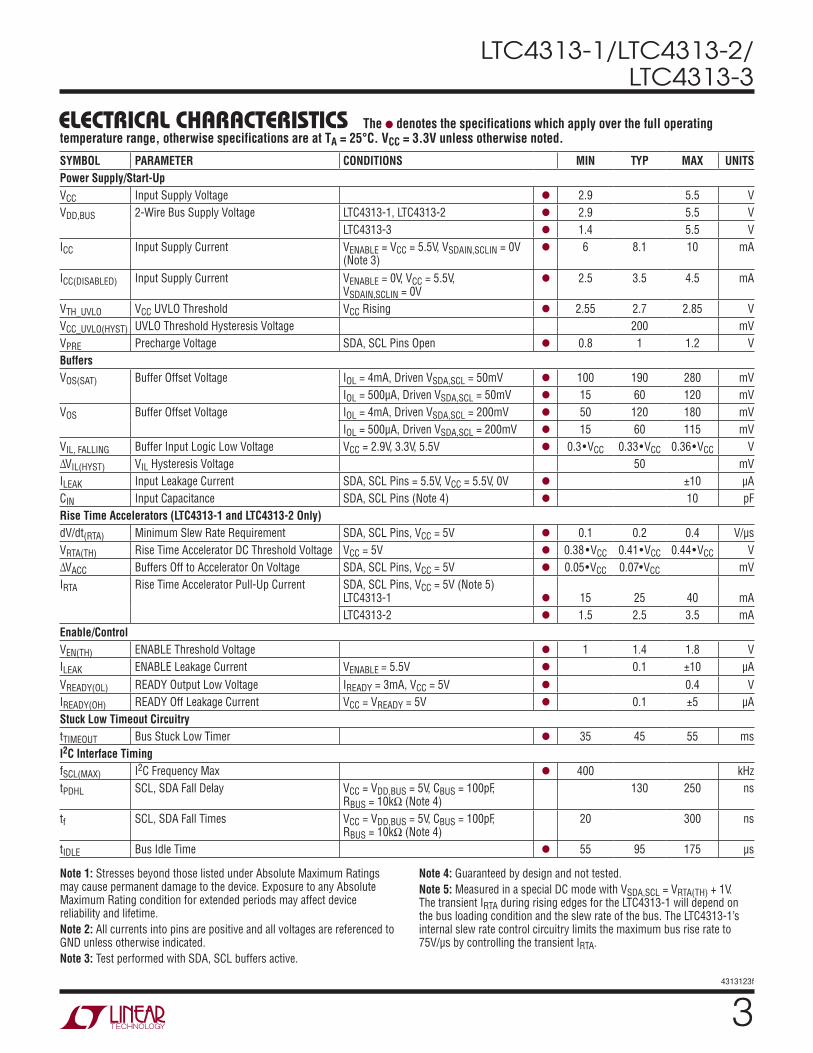
elecTrical characTerisTics
SYMBOL PARAMETER CONDITIONS MIN TYP MAX UNITSPower Supply/Start-UpVCC Input Supply Voltage l 2.9 5.5 VVDD,BUS 2-Wire Bus Supply Voltage LTC4313-1, LTC4313-2 l 2.9 5.5 V
LTC4313-3 l 1.4 5.5 VICC Input Supply Current VENABLE = VCC = 5.5V, VSDAIN,SCLIN = 0V
(Note 3)l 6 8.1 10 mA
ICC(DISABLED) Input Supply Current VENABLE = 0V, VCC = 5.5V, VSDAIN,SCLIN = 0V
l 2.5 3.5 4.5 mA
VTH_UVLO VCC UVLO Threshold VCC Rising l 2.55 2.7 2.85 VVCC_UVLO(HYST) UVLO Threshold Hysteresis Voltage 200 mVVPRE Precharge Voltage SDA, SCL Pins Open l 0.8 1 1.2 VBuffersVOS(SAT) Buffer Offset Voltage IOL = 4mA, Driven VSDA,SCL = 50mV l 100 190 280 mV
IOL = 500µA, Driven VSDA,SCL = 50mV l 15 60 120 mVVOS Buffer Offset Voltage IOL = 4mA, Driven VSDA,SCL = 200mV l 50 120 180 mV
IOL = 500µA, Driven VSDA,SCL = 200mV l 15 60 115 mVVIL, FALLING Buffer Input Logic Low Voltage VCC = 2.9V, 3.3V, 5.5V l 0.3•VCC 0.33•VCC 0.36•VCC V∆VIL(HYST) VIL Hysteresis Voltage 50 mVILEAK Input Leakage Current SDA, SCL Pins = 5.5V, VCC = 5.5V, 0V l ±10 µACIN Input Capacitance SDA, SCL Pins (Note 4) l 10 pFRise Time Accelerators (LTC4313-1 and LTC4313-2 Only)dV/dt(RTA) Minimum Slew Rate Requirement SDA, SCL Pins, VCC = 5V l 0.1 0.2 0.4 V/µsVRTA(TH) Rise Time Accelerator DC Threshold Voltage VCC = 5V l 0.38 •VCC 0.41•VCC 0.44•VCC V∆VACC Buffers Off to Accelerator On Voltage SDA, SCL Pins, VCC = 5V l 0.05•VCC 0.07•VCC mVIRTA Rise Time Accelerator Pull-Up Current SDA, SCL Pins, VCC = 5V (Note 5)
LTC4313-1
l
15
25
40
mA
LTC4313-2 l 1.5 2.5 3.5 mAEnable/ControlVEN(TH) ENABLE Threshold Voltage l 1 1.4 1.8 VILEAK ENABLE Leakage Current VENABLE = 5.5V l 0.1 ±10 µAVREADY(OL) READY Output Low Voltage IREADY = 3mA, VCC = 5V l 0.4 VIREADY(OH) READY Off Leakage Current VCC = VREADY = 5V l 0.1 ±5 µAStuck Low Timeout CircuitrytTIMEOUT Bus Stuck Low Timer l 35 45 55 msI2C Interface TimingfSCL(MAX) I2C Frequency Max l 400 kHztPDHL SCL, SDA Fall Delay VCC = VDD,BUS = 5V, CBUS = 100pF,
RBUS = 10kΩ (Note 4)130 250 ns
tf SCL, SDA Fall Times VCC = VDD,BUS = 5V, CBUS = 100pF, RBUS = 10kΩ (Note 4)
20 300 ns
tIDLE Bus Idle Time l 55 95 175 µs
The l denotes the specifications which apply over the full operating temperature range, otherwise specifications are at TA = 25°C. VCC = 3.3V unless otherwise noted.
Note 1: Stresses beyond those listed under Absolute Maximum Ratings may cause permanent damage to the device. Exposure to any Absolute Maximum Rating condition for extended periods may affect device reliability and lifetime.Note 2: All currents into pins are positive and all voltages are referenced to GND unless otherwise indicated.Note 3: Test performed with SDA, SCL buffers active.
Note 4: Guaranteed by design and not tested.Note 5: Measured in a special DC mode with VSDA,SCL = VRTA(TH) + 1V. The transient IRTA during rising edges for the LTC4313-1 will depend on the bus loading condition and the slew rate of the bus. The LTC4313-1’s internal slew rate control circuitry limits the maximum bus rise rate to 75V/µs by controlling the transient IRTA.

LTC4313-1/LTC4313-2/ LTC4313-3
44313123f
Typical perForMance characTerisTics
Buffer DC IOL vs Temperature
tF (70% to 30%) vs Bus Capacitance
tPDHL (50% to 50%) vs Bus Capacitance
LTC4313-1 IRTA vs Temperature
LTC4313-1 Bus Rise Time (40% to 70%) vs CBUS
ICC Enabled Current vs Supply Voltage
ICC Disabled Current vs Supply Voltage
TA = 25°C, VCC = 3.3V unless otherwise noted.
VCC (V)2
I CC
(mA)
9.0
8.0
7.0
8.5
7.5
6.5
6.043 5
4313213 G01
63.52.5 4.5 5.5
VSDAIN,SCLIN = 0VVENABLE = 5.5V
VCC (V)2
I CC
(mA)
4.0
3.0
3.5
2.5
2.043 52.5 4.53.5 5.5
4313213 G02
6
VSDAIN,SCLIN = 0VVENABLE = 0V
TEMPERATURE (°C)–50
I OL
(mA)
12
5
6
11
10
4
8
9
7
0 50
4313213 G03
100–25 25 75
VSDA,SCL = 0.6V
VSDA,SCL = 0.4V
VOS vs IBUS for Different Driven Voltage Levels
IBUS (mA)0
V OS
(mV)
250
200
150
0
50
100
1 3
4313213 G04
52 4
≥200mV
100mV
DRIVEN VSDA,SCL = 50mV
TEMPERATURE (°C)–50
I RTA
(mA)
16
8
10
6
14
12
0 50
4313213 G05
100–25 25 75
VCC = VDD,BUSVSDA,SCL = 0.6 • VDD,BUSCBUS = 400pF, RBUS = 10kΩ
5V
3.3V
CBUS (pF)0
t F (n
s)
100
75
50
0
25
600 800
4313213 G06
1000200 400
3.3V
5V
VCC = VDD,BUSRBUS = 10kΩ
CBUS (pF)0
t PDH
L (n
s)
200
175
150
100
125
600 800
4313213 G07
1000200 400
3.3V
5V
VCC = VDD,BUSRBUS = 10kΩ
CBUS (pF)0
t RIS
E (n
s)
75
5V
3.3V
100
600
4313123 G08
50
25200 400 800
VCC = VDD,BUS

LTC4313-1/LTC4313-2/ LTC4313-3
54313123f
pin FuncTionsENABLE (Pin 1): Connection Enable Input. When driven low, the ENABLE pin isolates SDAIN and SCLIN from SDAOUT and SCLOUT, asserts READY low, disables rise time accelerators and inhibits automatic clock and stop bit generation during a stuck low fault condition. When driven high, the ENABLE pin connects SDAIN and SCLIN to SDAOUT and SCLOUT after a stop bit or bus idle has been detected on both busses. Driving ENABLE high also enables automatic clock generation during a stuck low fault condition. During a stuck low fault condition, a rising edge on the ENABLE pin forces a connection between SDAIN and SDAOUT and SCLIN and SCLOUT. When using the LTC4313 in a Hot Swap™ application with staggered connector pins, connect a 10k resistor between ENABLE and GND to ensure correct functionality. Connect to VCC if unused.
SCLOUT (Pin 2): Serial Bus 2 Clock Input/Output. Connect this pin to the SCL bus segment where stuck low recovery is desired. Connect an external pull-up resistor or current source between this pin and the bus supply. The bus supply needs to be ≥ VCC for the LTC4313-1 and LTC4313-2, but not for the LTC4313-3. Refer to the Applications Informa-tion section for more details. Do not leave open.
SCLIN (Pin 3): Serial Bus 1 Clock Input/Output. Connect this pin to the SCL line on the upstream bus. Connect an external pull-up resistor or current source between this pin and the bus supply. The bus supply needs to be ≥ VCC for the LTC4313-1 and LTC4313-2, but not for the LTC4313-3. Refer to the Applications Information section for more details. Do not leave open.
GND (Pin 4): Device Ground.
READY (Pin 5): Connection Ready Status Output. This open drain N-channel MOSFET output pulls low when the input and output sides are disconnected. READY is pulled high when ENABLE is high and a connection has been established between the input and output. Connect a pull-up resistor, typically 10k from this pin to the bus pull-up supply. Leave open or tie to GND if unused.
SDAIN (Pin 6): Serial Bus 1 Data Input/Output. Connect this pin to the SDA line on the upstream bus. Connect an external pull-up resistor or current source between this pin and the bus supply. The bus supply needs to be ≥ VCC for the LTC4313-1 and LTC4313-2, but not for the LTC4313-3. Refer to the Applications Information section for more details. Do not leave open.
SDAOUT (Pin 7): Serial Bus 2 Data Input/Output. Connect this pin to the SDA bus segment where stuck low recovery is desired. Connect an external pull-up resistor or current source between this pin and the bus supply. The bus supply needs to be ≥ VCC for the LTC4313-1 and LTC4313-2, but not for the LTC4313-3. Refer to the Applications Informa-tion section for more details. Do not leave open.
VCC (Pin 8): Power Supply Voltage. Power this pin from a supply between 2.9V and 5.5V. Bypass with at least 0.01µF to GND.
Exposed Pad (Pin 9, DD8 Package Only): Exposed pad may be left open or connected to device GND.

LTC4313-1/LTC4313-2/ LTC4313-3
64313123f
block DiagraM
4313123 BD
CONNECT
LOGIC+–
+–
+
–
+
–
PRECHARGE
200k
PRECHARGECONNECT
PRECHARGECONNECT
200k
200k*
*
VCC
IRTA
SLEW RATEDETECTOR
0.2V/µs
SLEW RATEDETECTOR
0.2V/µs
200k
SLEW RATEDETECTOR
0.2V/µs
VCC
I2C Hot SwapLOGIC
I2C Hot SwapLOGIC
RTA_SDAOUT_EN
VIL = 0.33 • VCC
RTA_SCLIN_ENRTA_SDAIN_EN
RTA_SCLOUT_EN
VIL = 0.33 • VCC
ENABLE
*INSIDE DASHED BOX APPLIES ONLY TO THE LTC4313-1 AND LTC4313-2.
READY
GND
VCC+–
+–
2.7V/2.5V
1.4V/1.3V
UVLO 95µsTIMER
SLEW RATEDETECTOR
0.2V/µs
IRTA
VCC
IRTA
VCC
IRTA
VIL = 0.33 • VCC
VIL = 0.33 • VCC
PRECHARGECONNECT
CONNECT
45msTIMER
SDAIN
SCLIN
SDAOUT
SCLOUT
*
*

LTC4313-1/LTC4313-2/ LTC4313-3
74313123f
operaTionThe LTC4313 is a high noise margin bus buffer which provides capacitance buffering for I2C signals. Capacitance buffering is achieved by using back to back buffers on the clock and data channels which isolate the SDAIN and SCLIN capacitances from the SDAOUT and SCLOUT capacitances respectively. All SDA and SCL pins are fully bidirectional. The high noise margin allows the LTC4313 to operate with non-compliant I2C devices that drive a high VOL, permits a number of LTC4313s to be connected in series and improves the reliability of I2C communications in large noisy systems. Rise time accelerator (RTA) pull-up currents (IRTA) turn on during rising edges to reduce bus rise time for the LTC4313-1 and LTC4313-2. In a typical application the input and output busses are pulled up to VCC although this is not a requirement. If VDD,BUS is not tied to VCC, VDD,BUS must be greater than VCC to prevent overdrive of the bus by the RTAs for the LTC4313-1 and LTC4313-2. See the Applications Information section for VDD,BUS requirements for the LTC4313-3.
When the LTC4313 first receives power on its VCC pin, it starts out in an undervoltage lockout mode (UVLO) until its VCC exceeds 2.7V. The buffers and RTAs are disabled and the LTC4313 ignores the logic state of its clock and data pins. During this time the precharge circuit forces a nominal voltage of 1V on the SDA and SCL pins through 200k resistors.
Once the LTC4313 exits UVLO and its ENABLE pin has been asserted high, it monitors the clock and data pins for a stop bit or a bus idle condition. When a combination of either condition is detected simultaneously on the input and output sides, the LTC4313 activates the connection between SDAIN and SDAOUT, and SCLIN and SCLOUT, respectively, asserts READY high and deactivates the
precharge circuit. RTAs for the LTC4313-1 and LTC4313-2 are also enabled at this time.
When a SDA/SCL pin is driven below the VIL level, the buffers are turned on and the logic low level is propagated though the LTC4313 to the other side. A high occurs when all devices on the input and output sides release high. Once the bus voltages rise above the VIL level, the buffers are turned off. The RTAs are turned on at a slightly higher volt-age. The RTAs accelerate the rising edges of the SDA/SCL inputs and outputs up to a voltage of 0.9•VCC, provided that the busses on their own are rising at a minimum rate of 0.4V/µs as determined by the slew rate detectors. The RTAs are configured to operate in a strong slew limited switch mode in the LTC4313-1 and in the current source mode in the LTC4313-2.
The LTC4313 detects a bus stuck low (fault) condition when both clock and data busses are not simultaneously high at least once in 45ms. When a stuck bus occurs, the LTC4313 disconnects the input and output sides and after waiting at least 40µs, generates up to sixteen 5.5kHz clock pulses on the SCLOUT pin and a stop bit to attempt to free the stuck bus. Should the stuck bus release high during this period, automatic clock generation is terminated.
Once the stuck bus recovers, connection is re-established between the input and output after a stop bit or bus idle condition is detected. Toggling ENABLE after a fault condi-tion has occurred forces a connection between the input and output. When powering into a stuck low condition, the input and output sides remain disconnected even after the LTC4313 has exited the UVLO mode as a stop bit or bus idle condition is not detected on the stuck busses. After the timeout period, a stuck low fault condition is detected and the behavior is as described previously.

LTC4313-1/LTC4313-2/ LTC4313-3
84313123f
The LTC4313 provides capacitance buffering, data and clock Hot Swap capability and level translation. The high noise margin of the LTC4313 permits interoperability with I2C devices that drive a high VOL permits series connec-tion of multiple LTC4313s and improves I2C communica-tion reliability. The LTC4313 isolates backplane and card capacitances and provides slew control of falling edges while level translating 3.3V and 5V busses. The LTC4313-1 and LTC4313-2 also provide pull-up currents to accelerate rising edges. These features are illustrated in the following subsections.
Rise Time Accelerator (RTA) Pull-Up Current Strength (LTC4313-1 and LTC4313-2)
After an input and output connection has been established, the RTAs on both the input and output sides of the SDA and SCL busses are activated. During positive bus transi-tions of at least 0.4V/µs, the RTAs provide pull-up cur-rents to reduce rise time. The RTAs allow users to choose larger bus pull-up resistors to reduce power consumption and improve logic low noise margins, design with bus capacitances outside of the I2C specification or to oper-ate at a higher clock frequency. The LTC4313-1 regulates its RTA current to limit the bus rise rate to a maximum
applicaTions inForMaTion
Figure 1. Bus Rising Edge for the LTC4313-1. VCC = VDD,BUS = 5V Figure 2. Bus Rising Edge for the LTC4313-2. VCC = VDD,BUS = 5V
of 75V/µs. The current is therefore directly proportional to the bus capacitance. The LTC4313-1 RTA is capable of sourcing up to 40mA of current. Rise time acceleration for the LTC4313-2 is provided by a 2.5mA current source.
Figures 1 and 2 show the rising waveforms of heavily loaded SDAIN and SDAOUT busses for the LTC4313-1 and LTC4313-2 respectively. In both figures, during a rising edge, the buffers are active and the input and output sides are connected, until the bus voltages on both the input and output sides are greater than 0.3 • VCC. When each individual bus voltage rises above 0.41 • VCC, the RTA on that bus turns on. The effect of the acceleration strength is shown in the waveforms in Figures 1 and 2 for identi-cal bus loads. The RTAs of the LTC4313-1 and LTC4313-2 supply 10mA and 2.5mA of pull-up current respectively for the bus conditions shown in Figures 1 and 2. For identical bus loads, the bus rises faster in Figure 1 compared to Figure 2 because of the higher IRTA.
The RTAs are internally disabled during power-up and dur-ing a bus stuck low event. The RTAs when activated pull the bus up to 0.9•VCC on the input and output sides of the SDA and SCL pins. In order to prevent bus overdrive by the RTA, the bus supplies on the input and output sides
2V/DIV
1µs/DIV 4313123 F01
VCC = VDD,BUS = 5VRBUS = 20kCIN = COUT = 200pF
SDAIN
SDAOUT
2V/DIV
1µs/DIV 4313123 F02
VCC = VDD,BUS = 5VRBUS = 20kCIN = COUT = 200pF
SDAIN
SDAOUT

LTC4313-1/LTC4313-2/ LTC4313-3
94313123f
of the LTC4313-1 and LTC4313-2 must be greater than or equal to 0.9•VCC. An example is shown in Figure 3 where the input bus voltage is greater than VCC. During a rising edge, the input bus rise rate will be accelerated by the RTA up to a voltage of 2.97V after which the bus rise rate will reduce to a value that is determined by the bus current and bus capacitance. The RTA turn-off voltage is less than the bus supply and the bus is not overdriven.
Pull-Up Resistor Value Selection
To guarantee that the RTAs are activated during a rising edge, the bus must rise on its own with a positive slew rate of at least 0.4V/µs. To achieve this, choose a maximum RBUS using the formula:
RBUS ≤VDD,BUS(MIN) − VRTA(TH)( )
0.4Vµs
• CBUS (1)
RBUS is the pull-up resistor, VDD,BUS(MIN) is the minimum bus pull-up supply voltage, VRTA(TH) is the voltage at which the RTA turns on and CBUS is the equivalent bus capaci-tance. RBUS must also be large enough to guarantee that:
RBUS ≥
VDD,BUS(MAX) − 0.4V( )4mA
(2)
This criterion ensures that the maximum bus current is less than 4mA.
applicaTions inForMaTionInput to Output Offset Voltage
While propagating a logic low voltage on its SDA and SCL pins, the LTC4313 introduces a positive offset voltage between the input and output. When a logic low voltage ≥200mV is driven on any of the LTC4313’s clock or data pins, the LTC4313 regulates the voltage on the opposite side to a slightly higher value. This is illustrated in Equa-tion 3, which uses SDA as an example:
VSDAOUT = VSDAIN + 50mV + 15Ω •
VDD,BUS
RBUS (3)
In Equation 3, VDD,BUS is the output bus supply voltage and RBUS is the SDAOUT bus pull-up resistance.
For driven logic low voltages < 200mV Equation 3 does not apply as the saturation voltage of the open collector output transistor results in a higher offset. For a driven input logic low voltage below 220mV, the output is guaranteed to be below a VOL of 400mV for bus pull-up currents up to 4mA. See the Typical Performance Characteristics section for offset variation as a function of the driven logic low voltage and bus pull-up current.
Figure 3. Level Shift Application Where the SDAIN and SCLIN Bus Pull-Up Supply Voltage Is Higher Than the Supply Voltage of the LTC4313
LTC4313-1
GND
VCC
4313123 F03
READY
SCLOUT
SDAOUT
ENABLE
SCLIN
SDAIN
SCL1
SDA1
R210k
C10.01µFR1
10k
5V
READY
SCL2
SDA2
R410k
R310k
3.3V
R510k

LTC4313-1/LTC4313-2/ LTC4313-3
104313123f
applicaTions inForMaTionFalling Edge Characteristics
The LTC4313 introduces a propagation delay on falling edges due to the finite response time and the finite current sink capability of the buffers. In addition the LTC4313 also slew limits the falling edge to an edge rate of 45V/µs (typ). The slew limited falling edge eliminates fast transitions on the busses and minimizes transmission line effects in systems. Refer to the Typical Performance Characteristics section for the propagation delay and fall times as a func-tion of the bus capacitance.
Stuck Bus Disconnect and Recovery
During an output bus stuck low condition (SCLOUT and SDAOUT have not been simultaneously high at least once in 45ms), the LTC4313 attempts to unstick the bus by first breaking the connection between the input and output. After
40µs the LTC4313 generates up to sixteen 5.5KHz clock pulses on the SCLOUT pin. Should the stuck bus release high during this period, clock generation is stopped and a stop bit is generated. This process is shown in Figure 4 for the case where SDAOUT starts out stuck low and then recovers. As seen from Figure 4, the LTC4313 pulls READY low and breaks the connection between the input and output sides, when a stuck low condition on SDA is detected. Clock pulses are then issued on SCLOUT to at-tempt to unstick the SDAOUT bus. When SDAOUT recovers, clock pulsing is stopped, a stop bit is generated on the output and READY is released high. When powering up into a stuck low condition, a connection is never made between the input and the output, as a stop bit or bus idle condition is never detected. After a timeout period of 45ms, the behavior is the same as described previously.
Figure 4. Bus Waveforms During SDAOUT Stuck Low and Recovery Event
4313123 F04
SCLOUT5V/DIV
READY5V/DIV
SDAIN5V/DIV
SDAOUT5V/DIV
1ms/DIV
DISCONNECTAT TIMEOUT
STUCK LOW > 45ms
AUTOMATIC CLOCKING
RECOVERS HIGH
DRIVEN LOW
STOP BIT GENERATED

LTC4313-1/LTC4313-2/ LTC4313-3
114313123f
applicaTions inForMaTionLive Insertion and Capacitance Buffering Application
Figure 5 illustrates an application of the LTC4313 that takes advantage of the LTC4313’s Hot Swap, capacitance buffer-ing and precharge features. If the I/O cards were plugged directly into the backplane without LTC4313 buffers, all of the backplane and card capacitances would directly add together, making rise time requirements difficult to meet. Placing an LTC4313 on the edge of each card isolates the card capacitance from the backplane. For a given I/O card, the LTC4313 drives the capacitance of everything on the card and the devices on backplane must drive only the small capacitance of the LTC4313 which is < 10pF.
In Figure 5 a staggered connector is used to connect the LTC4313 to the backplane. VCC and GND are the longest pins to ensure that the LTC4313 is powered and forcing a 1V precharge voltage on the medium length SDA and SCL pins before they contact the backplane. The 1V pre-charge voltage is applied to the SDA and SCL pins through 200k resistors. Since cards are being plugged into a live backplane whose SDA and SCL busses could be at any voltage between 0 and VCC, precharging the LTC4313’s SDA and SCL pins to 1V minimizes disturbances to the backplane bus when cards are being plugged in. The low (< 10pF) input capacitance of the LTC4313 also contributes to minimizing bus disturbance as cards are being plugged in. With ENABLE being the shortest pin and also pulled to GND by a resistor, the staggered approach provides ad-
ditional time for transients associated with live insertion to settle before the LTC4313 can be enabled. A 10k or lower pull-down resistor from ENABLE to GND is recommended.
If a connector is used where all pins are of equal length, the benefit of the precharge circuit is lost. Also, the ENABLE signal to the LTC4313 must be held low until all the transients associated with card insertion into a live system die out.
Level Translating to Voltages < 2.9V (LTC4313-3 Only)
The LTC4313-3 can be used for level translation to bus voltages below 2.9V. Since the maximum buffer turn-on and turn-off voltages are 0.36•VCC, the minimum bus supply voltage is determined by the following equation,
VDD,BUS(MIN) ≥
0.36 • VCC
0.7 (4)
in order to meet the VIH = 0.7 • VDD,BUS requirement and not impact the high side noise margin. Users willing to live with a lower logic high noise margin can level translate down to 1.4V. An example of voltage level translation from 3.3V to 1.8V is illustrated in Figure 6, where a 3.3V input voltage bus is translated to a 1.8V output voltage bus. Tying VCC to 3.3V satisfies Equation 4. A similar voltage translation can also be performed going from a 3.3V bus supply on the output side to a 1.8V input if the VCC pin of the LTC4313-3 is tied to the 3.3V output supply.

LTC4313-1/LTC4313-2/ LTC4313-3
124313123f
applicaTions inForMaTion
Figure 5. LTC4313 in an I2C Hot Swap Application with a Staggered Connector
R610k
R410k
R510k
LTC4313
GND
VCC
SCLOUT
SDAOUT
READY
SCLIN
SDAIN
ENABLE
C20.01µF
CARD 1_SCL
CARD 1_SDA
CARD N_SCL
CARD N_SDA
C10.01µF
R910k
4313123 F05
R710k
I/O PERIPHERAL CARD N
I/O PERIPHERAL CARD 1CARD
CONNECTORBACKPLANECONNECTOR
R810k
LTC4313
GND
VCC
SCLOUT
SDAOUT
READY
SCLIN
SDAIN
ENABLE
C40.01µF
C30.01µF
R310k
R110k
R210k
READY
SCL
SDA
ENABLE 1
5V
3.3V
ENABLE N
• • •
• • •
Figure 6. Voltage Level Translation from 3.3V to 1.8V Using the LTC4313-3
LTC4313-3
GND
VCC
4313123 F06
READY
SCLOUT
SDAOUT
ENABLE
SCLIN
SDAINSCL1
SDA1
R210k
R510k
R410k
R310k
R110k
3.3V
READY
SCL2
SDA2
1.8V
C10.01µF

LTC4313-1/LTC4313-2/ LTC4313-3
134313123f
applicaTions inForMaTionTelecommunications Systems
The LTC4313 has several features that make it an excellent choice for use in telecommunication systems such as ATCA. Referring to Figures 7 and 8, buffers are used on the edges of the field replaceable units (FRU) and shelf managers to shield devices on these cards from the large backplane capacitance. The input capacitance of the LTC4313 is less than the 10pF maximum specification for buffers used in bussed ATCA applications. The LTC4313 buffers can drive capacitances >1nF, which is greater than the maximum backplane capacitance of 690pF in bussed ATCA systems. The precharge feature, low input capacitance and high impedance of the SDA and SCL pins of the LTC4313 when
it is unpowered, minimize disturbances to the bus when cards are being hot swapped. In Figure 7, the RTA of the LTC4313-2 on the shelf manager supplies sufficient pull-up current, allowing the 1µs rise time requirement to be met on the heavily loaded backplane for loads well beyond the 690pF maximum specification. The 0.33 • VCC turn-off voltage of the LTC4313’s buffers provides a large logic low noise margin in these systems. In the bussed ATCA application shown in Figure 7, the LTC4313s located on the shelf managers #1 and #2 and on the FRUs, drive the large backplane capacitance while the microcontrollers on the shelf managers and the I2C slave devices on the FRUs drive the small input capacitance of the LTC4313-3.
Figure 7. LTC4313s Used in a Bussed ATCA Application. Only the Clock Path is Shown for Simplicity
LTC4313-2µP
VCC
3.3V
SCLOUTSCLIN
ENABLE
R110k
R22.7k
4313123 F07
BACKPLANE
IPMB-ASCL
IPMB-BSCL
SHELF MANAGER #1
SHELF MANAGER #2IDENTICAL TO SHELF MANAGER #1
TO SHMC#2
TO SHMC#2
IPMB-B
IPMB-B DETAILS (NOT SHOWN) ARE IDENTICAL TO IPMB-A
FRU #1
LTC4313-3
I2CDEVICE3.3V
3.3V
SCLOUT
VCC
SCLIN
R310k
R410k
LTC4313-3
SCLOUT
VCC
SCLIN
FRU #N
LTC4313-3
I2CDEVICE3.3V
3.3V
SCLOUT
VCC
SCLIN
R610k
R510k
LTC4313-3
SCLOUT
VCC
SCLIN
• • •

LTC4313-1/LTC4313-2/ LTC4313-3
144313123f
applicaTions inForMaTionThe LTC4313-2 on only one of the shelf managers is enabled at any given time. The hot insertion logic on the LTC4313-3 allows the FRUs to be plugged or unplugged from a live backplane. The features mentioned previously provide noise immunity and allow timing specifications to be met for a wide range of backplane loading conditions.
In the 6 × 4 radial configuration shown in Figure 8, the LTC4314s on the shelf managers and the LTC4313-2s on the FRUs drive the large backplane capacitance while the I2C slave devices on the FRUs only drive the small input capacitance of the LTC4313-2s. The LTC4314s on only one of the shelf managers are enabled at a given time. All
the benefits provided by the LTC4313-2 in Figure 7 apply to Figure 8 as well.
Cascading and Interoperability with Other LTC Buffers and Non-Compliant I2C Devices
Multiple LTC4313s can be cascaded or the LTC4313 can be cascaded with other LTC bus buffers. Cascades often exist in large I2C systems, where multiple I/O cards having bus buffers connect to a common backplane bus. Two issues need to be considered when using such cascades – the additive nature of the buffer logic low offset voltages and the impact of the RTA-buffer interaction on the noise margin.
Figure 8. LTC4313-2 Used in a Radially Connected Telecommunication System in a 6 × 4 Arrangement. Only the Clock Path is Shown for Simplicity. The Data Pathway is Identical
SHELF MANAGER #1
IPMB-A(X24)
IPMB-B(X24)
SCL1
SCL24
SCL1
SCL24
3.3V
R210kLTC4314#1
VCC VCC2
SCLOUT1
SCLOUT2
SCLOUT3
SCLOUT4
SCLIN
ENABLE1
ENABLE2
ENABLE3
ENABLE4
ACC
ENABLE1A
ENABLE2A
ENABLE3A
ENABLE4A
ENABLE21A
ENABLE22A
ENABLE23A
ENABLE24A
R110k
µP
3.3V
3.3V
IPMB-B DETAILS (NOT SHOWN) ARE IDENTICAL TO IPMB-AIPMB-B
R510kLTC4314#6
VCC VCC2
SCLOUT1
SCLOUT2
SCLOUT3
SCLOUT4
SCLIN
ENABLE1
ENABLE2
ENABLE3
ENABLE4
ACC
3.3V
4313123 F08
BACKPLANE
IPMB-BSCL24
3.3V
IPMB-ASCL1
IPMB-ASCL24
IPMB-BSCL1
FRU #1
LTC4313-2
I2CDEVICE
3.3V
SCLOUT
VCC
SCLIN
R310k
R410k
LTC4313-2
SCLOUT
VCC
SCLIN
FRU #24
3.3V
LTC4313-2
I2CDEVICE
3.3V
SCLOUT
VCC
SCLIN
R610k
R710k
LTC4313-2
SCLOUT
VCC
SCLINSHELF MANAGER #2
IDENTICAL TO SHELF MANAGER #1
• • •• • •
• • •
• • •
• • •

LTC4313-1/LTC4313-2/ LTC4313-3
154313123f
applicaTions inForMaTionFirst, when two or more buffers are connected in a cas-cade configuration, if the sum of the offsets across the cascade (refer to Equation 3 and the data sheets of the corresponding buffers) plus the worst-case driven logic low voltage exceeds the minimum buffer turn-off voltage, signals will not be propagated across the cascade. The maximum driven logic low voltage must be set accordingly, for correct operation in such cascades.
Second, noise margin is affected by cascading the LTC4313 with buffers whose RTA turn-on voltage is lower than the LTC4313 buffer turn-off voltage. The VIL for the LTC4313 is set to 0.3 • VCC to achieve high noise margin provided that the LTC4313 buffers do not contend with RTAs of other products. To maximize logic low noise margin, dis-able the RTAs of the other LTC buffers if possible and use the RTAs of the LTC4313 in cascading applications. To permit interoperability with other LTC buffers whose RTAs cannot be disabled, the LTC4313 senses the RTA current and turns off its buffers below 0.3 • VCC. This eliminates contention between the LTC4313 buffers and other RTAs, making the SDA/SCL waveforms monotonic.
Figures 9 shows the LTC4313-1 operating on a bus shared with LTC4300A and LTC4307 buffers. The correspond-ing SCL waveforms are shown in Figure 10. The RTAs on the LTC4300A and the LTC4307 cannot be disabled. The backplane in Figure 9 has five I/O cards connected to it. Each I/O card has a LTC bus buffer on its outside edge for SDA/SCL Hot Swap onto the backplane. In this example, there are three LTC4300As, one LTC4307 and one LTC4313-1. The SCL1 bus is driven by an I2C master (master not shown). When the SCL2 voltage crosses 0.6V and 0.8V, the RTAs on the LTC4300A and LTC4307 turn on respectively and source current into SCL2. The LTC4313-1 detects this and turns off its buffers, releasing SCL1 and SCL2 high. Contention between the LTC4313-1 buffers and the LTC4300A and LTC4307 RTAs is prevented and the SCL1, SCL2 and SCL3 waveforms in Figure 10 are monotonic. The logic low noise margin is reduced because the LTC4313-1 buffers turn off when the SCL1 voltage is approximately 0.6V.
Generally, noise margin will be reduced if other RTAs turn on at a voltage less than 0.3•VCC. The reduction in noise margin is a function of the number of LTC4313s and the
number and turn-on voltage of other RTAs, whose current must be sunk by the LTC4313 buffers. The same arguments apply for non-LTC buffer products whose RTA turn-on voltage is less than 0.3•VCC.
Interoperability is improved by reducing the interaction time between the LTC4313 buffers and other RTAs by reducing R1 and CB1. The following guidelines are recommended for single supply systems,
a. For 5V systems choose R1 < 20kΩ and CB1 < 1nF. There are no other constraints.
b. For 3.3V systems, refer to Figures 11 and 12 for opera-tion with LTC4300As and LTC4307s. In the figures,
M =
Number of LTC4300As or LTC4307sNumber of LTC4313s
R1 and CB1 must be chosen to be below the curves for a specific value of M. For M greater than the val-ues shown in the figures, non-idealities do not result. R1 <20kΩ and CB1 <1nF are still recommended.
The LTC4313 is interoperable with non-compliant I2C devices that drive a high VOL > 0.4V. Figure 13 shows the LTC4313-1 in an application where a microcontroller com-municates through the LTC4313-1 with a non-compliant I2C device that drives a VOL of 0.6V. The LTC4313 buffers are active up to a bus voltage of 0.3•VCC which is 1.089V in this case, yielding a noise margin of 0.489V.
Repeater Application
Multiple LTC4313s can be cascaded in a repeater applica-tion where a large 2-wire system is broken into smaller sections as shown in Figure 14. The high noise margin and low offset of the LTC4313 allows multiple devices to be cascaded while still providing good system level noise margin. In the repeater circuit shown in Figure 14 if SCL1/SDA1 is driven externally to 200mV, SCL2/SDA2 is regulated to ~440mV worst-case by the cascade of LTC4313-1s. The buffer turn-off voltage is 1.089V, yield-ing a minimum logic low noise margin of ~650mV. In Figure 14, use of the RTAs combined with an increased level of buffering reduces transition times and permits operation at a higher frequency.

LTC4313-1/LTC4313-2/ LTC4313-3
164313123f
applicaTions inForMaTion
Figure 9. The LTC4313-1 Operating in a Cascade with Other LTC Buffers with Active RTAs. Only the Clock Pathway is Shown for Simplicity
LTC4313-1
GND
VCC
SCLOUTSCLINSCL1SCL2
R15k
C10.01µF
3.3V
LTC4300A
GND
VCC
SCLOUT SCL3SCLIN
R32.7k
5V
R22.7k
4313123 F09
CB1100pF
* CB2 690pF
LTC4307
GND
VCC
SCLOUT SCL4
I/O CARD #5
I/O CARD #2-4
SCLIN
R45k
BACKPLANE
I/O CARD #1
* PARASITIC BACKPLANE CAPACITANCE
Figure 10. Corresponding SCL Switching Waveforms. No Glitches Are Seen
2V/DIV
2V/DIV
2V/DIV
1µs/DIV4313123 F10
LTC4300A/LTC4307RTAs TURN ON
LTC4313BUFFERSTURN OFF
LTC4313-1RTA ON
SCL2
SCL3
SCL1

LTC4313-1/LTC4313-2/ LTC4313-3
174313123f
applicaTions inForMaTion
Figure 11. Recommended Maximum R1 and CB1 Values for the LTC4313 Operating with Multiple LTC4300As in a 3.3V System
Figure 12. Recommended Maximum R1 and CB1 Values for the LTC4313 Operating with Multiple LTC4307s in a 3.3V System
Figure 14. LTC4313-1s in a Repeater Application
RBUS (kΩ)0
C BUS
(pF)
100
1000
8
4313123 F11
102 64 10
M = 1
M = 2M = 3
RBUS (kΩ)0
C BUS
(pF)
1000
10000
8
4313123 F12
1002 64 10
M = 1
LTC4313-1
GND
VCC
4313123 F14
READY
SCLOUT
SDAOUT
ENABLE
SCLIN
SDAINSCL1
SDA1
R210k
R310k
R410k
R110k
C10.01µF
3.3V
LTC4313-3
GND
VCC
READY
SCLOUT
SDAOUT
ENABLE
SCLIN
SDAIN
LTC4313-1
GND
VCC
READY
SCLOUT
SDAOUT
ENABLE
SCLIN
SDAIN
R610k
R510k
R910k
R810k
R710k
SCL2
SDA2
Figure 13. Communication with a Non-Compliant I2C Device Using the LTC4313
LTC4313
GND
VCC
4313123 F13
SCLOUT
SDAOUT
DISCEN
ENABLE
READY
SCLIN
SDAIN
R510k
R310k
R210k
R110k
R410k
C10.01µF
NON-COMPLIANTI2C DEVICEVOL = 0.6V
5V3.3V
µP

LTC4313-1/LTC4313-2/ LTC4313-3
184313123f
package DescripTion
DD8 Package8-Lead Plastic DFN (3mm × 3mm)
(Reference LTC DWG # 05-08-1698 Rev C)
3.00 ±0.10(4 SIDES)
NOTE:1. DRAWING TO BE MADE A JEDEC PACKAGE OUTLINE M0-229 VARIATION OF (WEED-1)2. DRAWING NOT TO SCALE3. ALL DIMENSIONS ARE IN MILLIMETERS4. DIMENSIONS OF EXPOSED PAD ON BOTTOM OF PACKAGE DO NOT INCLUDE MOLD FLASH. MOLD FLASH, IF PRESENT, SHALL NOT EXCEED 0.15mm ON ANY SIDE5. EXPOSED PAD SHALL BE SOLDER PLATED6. SHADED AREA IS ONLY A REFERENCE FOR PIN 1 LOCATION ON TOP AND BOTTOM OF PACKAGE
0.40 ± 0.10
BOTTOM VIEW—EXPOSED PAD
1.65 ± 0.10(2 SIDES)
0.75 ±0.05
R = 0.125TYP
2.38 ±0.10
14
85
PIN 1TOP MARK
(NOTE 6)
0.200 REF
0.00 – 0.05
(DD8) DFN 0509 REV C
0.25 ± 0.05
2.38 ±0.05
RECOMMENDED SOLDER PAD PITCH AND DIMENSIONSAPPLY SOLDER MASK TO AREAS THAT ARE NOT SOLDERED
1.65 ±0.05(2 SIDES)2.10 ±0.05
0.50BSC
0.70 ±0.05
3.5 ±0.05
PACKAGEOUTLINE
0.25 ± 0.050.50 BSC
Please refer to http://www.linear.com/designtools/packaging/ for the most recent package drawings.

LTC4313-1/LTC4313-2/ LTC4313-3
194313123f
Information furnished by Linear Technology Corporation is believed to be accurate and reliable. However, no responsibility is assumed for its use. Linear Technology Corporation makes no representa-tion that the interconnection of its circuits as described herein will not infringe on existing patent rights.
package DescripTion
MS8 Package8-Lead Plastic MSOP
(Reference LTC DWG # 05-08-1660 Rev F)
MSOP (MS8) 0307 REV F
0.53 ± 0.152(.021 ± .006)
SEATINGPLANE
NOTE:1. DIMENSIONS IN MILLIMETER/(INCH)2. DRAWING NOT TO SCALE3. DIMENSION DOES NOT INCLUDE MOLD FLASH, PROTRUSIONS OR GATE BURRS. MOLD FLASH, PROTRUSIONS OR GATE BURRS SHALL NOT EXCEED 0.152mm (.006") PER SIDE4. DIMENSION DOES NOT INCLUDE INTERLEAD FLASH OR PROTRUSIONS. INTERLEAD FLASH OR PROTRUSIONS SHALL NOT EXCEED 0.152mm (.006") PER SIDE5. LEAD COPLANARITY (BOTTOM OF LEADS AFTER FORMING) SHALL BE 0.102mm (.004") MAX
0.18(.007)
0.254(.010)
1.10(.043)MAX
0.22 – 0.38(.009 – .015)
TYP
0.1016 ± 0.0508(.004 ± .002)
0.86(.034)REF
0.65(.0256)
BSC
0° – 6° TYP
DETAIL “A”
DETAIL “A”
GAUGE PLANE
1 2 3 4
4.90 ± 0.152(.193 ± .006)
8 7 6 5
3.00 ± 0.102(.118 ± .004)
(NOTE 3)
3.00 ± 0.102(.118 ± .004)
(NOTE 4)
0.52(.0205)
REF
5.23(.206)MIN
3.20 – 3.45(.126 – .136)
0.889 ± 0.127(.035 ± .005)
RECOMMENDED SOLDER PAD LAYOUT
0.42 ± 0.038(.0165 ± .0015)
TYP
0.65(.0256)
BSC
Please refer to http://www.linear.com/designtools/packaging/ for the most recent package drawings.

LTC4313-1/LTC4313-2/ LTC4313-3
204313123f
Linear Technology Corporation1630 McCarthy Blvd., Milpitas, CA 95035-7417 (408) 432-1900 FAX: (408) 434-0507 www.linear.com LINEAR TECHNOLOGY CORPORATION 2011
LT 1011 • PRINTED IN USA
relaTeD parTs
Typical applicaTion
PART NUMBER DESCRIPTION COMMENTS
LTC4300A-1/LTC4300A-2/LTC4300A-3
Hot Swappable 2-Wire Bus Buffers -1: Bus Buffer with READY and ENABLE -2: Dual Supply Buffer with ACC -3: Dual Supply Buffer and ENABLE
LTC4302-1/LTC4302-2
Addressable 2-Wire Bus Buffer Address Expansion, GPIO, Software Controlled
LTC4303/ LTC4304
Hot Swappable 2-Wire Bus Buffer with Stuck Bus Recovery
Provides Automatic Clocking to Free Stuck I2C Busses
LTC4305/ LTC4306
2- or 4-Channel, 2 Wire Bus Multiplexers with Capacitance Buffering
Two or Four Software Selectable Downstream Busses, Stuck Bus Disconnect, Rise Time Accelerators, Fault Reporting, ±5kV HBM ESD
LTC4307 Low Offset Hot Swappable 2-Wire Bus Buffer with Stuck Bus Recovery
60mV Bus Offset, Rise Time Accelerators, ±5kV HBM ESD
LTC4307-1 High Definition Multimedia Interface (HDMI) Level Shifting 2-Wire Bus Buffer
60mV Buffer Offset, 3.3V to 5V Level Shifting, 30ms Stuck Bus Disconnect and Recovery, ±5kV HBM ESD
LTC4308 Low Voltage, Level Shifting Hot Swappable 2-Wire Bus Buffer with Stuck Bus Recovery
Bus Buffer with 1V Precharge, ENABLE and READY, 0.9V to 5.5V Level Translation, 30ms Stuck Bus Disconnect and Recovery, Output Side Rise Time Accelerators, ±6kV HBM ESD
LTC4309 Low Offset Hot Swappable 2-Wire Bus Buffer with Stuck Bus Recovery
60mV Buffer Offset, 30ms Stuck Bus Disconnect and Recovery, Rise Time Accelerators, ±5kV HBM ESD, 1.8V to 5.5V Level Translation
LTC4310-1 LTC4310-2
Hot Swappable I2C Isolators Bidirectional I2C Communication Between Two Isolated Busses, LTC4310-1: 100kHz Bus, LTC4310-2: 400kHz Bus
LTC4311 Low Voltage I2C/SMBus Accelerator Rise Time Acceleration with ENABLE and ±8kV HBM ESD
LTC4312/ LTC4314
2- or 4-Channel, Hardware Selectable 2 Wire Bus Multiplexers with Capacitance Buffering
Two or Four Pin Selectable Downstream Busses, VIL Up to 0.3•VCC, Stuck Bus Disconnect, Rise time Accelerators, 45ms Stuck Bus Disconnect and Recovery, ±4kV HBM ESD
LTC4315 High Noise Margin 2-Wire Bus Buffer VIL = 0.3•VCC, Rise Time Accelerators, Stuck Bus Disconnect, 1V Precharge, ENABLE and READY Pins, ±4kV HBM ESD
Cascaded Application with Level Shifting and Operation with a Non-Compliant I2C Device
LTC4313-3
GND
VCC
4313123 TA02
READY
SCLOUT
SDAOUT
ENABLE
SCLIN
SDAIN
SCL1
SDA1
SCL2
SDA2
R210k
R310k
R410k
R110k
C10.01µF
2.5V 3.3V 5V
LTC4313-2
GND
BACKPLANE ORLONG CABLE RUN
VCC
READY
SCLOUT
SDAOUT
ENABLE
SCLIN
SDAIN
R710k
R610k
R510k
NON-COMPLIANTI2C DEVICEVOL = 0.6V

Mouser Electronics
Authorized Distributor
Click to View Pricing, Inventory, Delivery & Lifecycle Information: Analog Devices Inc.:
LTC4313IDD-3#PBF LTC4313IMS8-1#TRPBF LTC4313CMS8-2#TRPBF LTC4313IMS8-3#PBF LTC4313IDD-
1#PBF LTC4313CDD-2#PBF LTC4313CDD-1#PBF LTC4313CMS8-3#PBF LTC4313IMS8-2#PBF LTC4313CDD-
2#TRPBF LTC4313IMS8-3#TRPBF LTC4313IDD-3#TRPBF LTC4313CMS8-3#TRPBF LTC4313CMS8-1#TRPBF
LTC4313IDD-2#PBF LTC4313CDD-1#TRPBF LTC4313IMS8-1#PBF LTC4313CDD-3#TRPBF LTC4313CMS8-
2#PBF LTC4313CDD-3#PBF LTC4313IDD-2#TRPBF LTC4313CMS8-1#PBF LTC4313IDD-1#TRPBF
LTC4313IMS8-2#TRPBF