ltr: transmits hydrogeologic workplan modifications, … · mr. tom gardner republic services of...
TRANSCRIPT

SDMSDocID 2030079

2030079
6EOTECHNICAL &ENVIRONMENTALSERVICES, INC.
PROVIDING• Geotechnical
Engineering• Construction
MaterialsEngineering
• EnvironmentalEngineering
• DrillingServices
June 19, 2001Project No. 98744D1
Ms. Susanna TrujilloProject CoordinatorU.S. EPA Region IX75 Hawthorne Street (WST-7)San Francisco, CA 94105-3901
Re: Hydrogeologic Workplan Modifications, Sunrise Landfill HydrogeologicEvaluation, Clark County, Nevada
Dear Ms. Trujillo:
On behalf of RepublicEnvironmental Services,hydrogeologic portion ofand approved, throughknowledge and consentGES, SCS, IT Corp andhave been reviewed and
Services of Southern Nevada (RSSN), Geotechnical &Inc. (GES) is submitting the attached modifications to thethe approved workplan. These changes were developeda cooperative effort, over a period of time with thebetween the EPA, the EPA representative (SAIC), RSSN,BLM. We understand the enclosed written modificationsapproved by SCS, IT Corp and RSSN representatives.
If you have any questions regarding this submittal, contact Republic Services ofSouthern Nevada at 702-734-5400.
Sincerely,
Geotechnical & Environmental Services, Inc.
Daniel C. Burns, C.E.M.#1692 (Expires 10/07/2001;Project Managing Geologist
Gregory PybeSart, P.E., C.E.M.#1172 (Exfires 12/22/2002)President
Distribution by U.S. Mail, unless otherwise noted.2 originals to addressee1 copy to file
Mr. Steve Wall (WST-7)Technical CoordinatorUnited States Environmental Protection AgencyRegion 975 Hawthorne StreetSan Francisco, CA 94105-3901
7150 Placid Street Las Vegas, NV 89119(702)365-1001 • Fax (702) 341-7120
www.gesnevada.com
U.S. EPA Region IXProject No. 98744D1June 19, 2001Page 2
Ms. Sherri McMahonClark County Comprehensive PlanningEnvironmental Planning Division500 S. Grand Central Pky.Las Vegas, NV 89155-1745
Mr. Mike MoranBureau of Land Management4765 Vegas DriveLas Vegas, NV 89108
Mr. Brent Lewis, P.G.Bureau of Land ManagementDenver Federal CenterBuilding 50Denver, CO 80225-0047
Ms. Sandy DotySAIC5303 W. Oberlin Dr.Denver, CO 80325
Mr. Alan GaddyRepublic Services of Southern Nevada770 East Sahara AvenueLas Vegas, NV 89103Deliver
Mr. Tom GardnerRepublic Services of Southern NevadaApex Regional Waste Management Center13550 N. US Highway 93Las Vegas, NV 89124Transmit coversheet by Fax only to 735-4523
Mr. Steve Smith, P.E.SCS Engineers2702 North 44th StreetSuite 105BPhoenix, Arizona 85008
Mr. Daniel Easter, R.G.EMCON1921 Ring wood AvenueSan Jose, California 95131
j:\jobs\98Jobs\98744\final work plan & sap\hydroworkplanmodcvrltr.doc
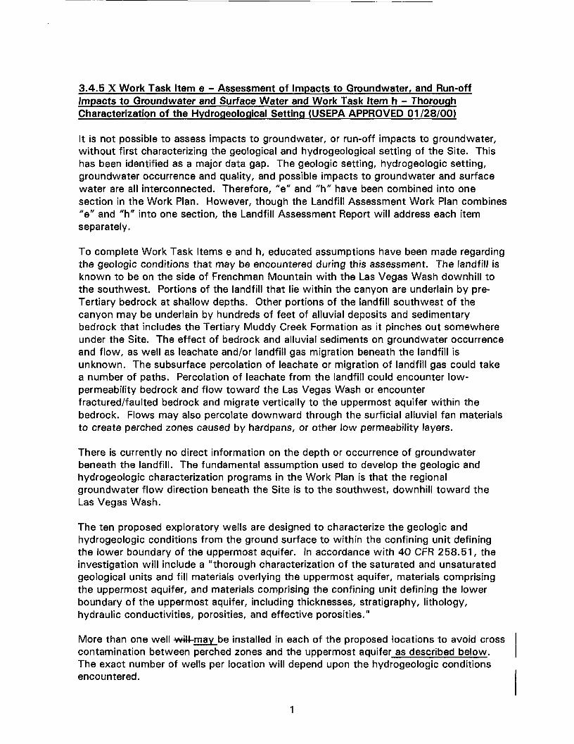
3.4.5 X Work Task Item e - Assessment of Impacts to Groundwater, and Run-offImpacts to Groundwater and Surface Water and Work Task Item h - ThoroughCharacterization of the Hydrogeological Setting (USEPA APPROVED 01/28/00)
It is not possible to assess impacts to groundwater, or run-off impacts to groundwater,without first characterizing the geological and hydrogeological setting of the Site. Thishas been identified as a major data gap. The geologic setting, hydrogeologic setting,groundwater occurrence and quality, and possible impacts to groundwater and surfacewater are all interconnected. Therefore, "e" and "h" have been combined into onesection in the Work Plan. However, though the Landfill Assessment Work Plan combines"e" and "h" into one section, the Landfill Assessment Report will address each itemseparately.
To complete Work Task Items e and h, educated assumptions have been made regardingthe geologic conditions that may be encountered during this assessment. The landfill isknown to be on the side of Frenchman Mountain with the Las Vegas Wash downhill tothe southwest. Portions of the landfill that lie within the canyon are underlain by pre-Tertiary bedrock at shallow depths. Other portions of the landfill southwest of thecanyon may be underlain by hundreds of feet of alluvial deposits and sedimentarybedrock that includes the Tertiary Muddy Creek Formation as it pinches out somewhereunder the Site. The effect of bedrock and alluvial sediments on groundwater occurrenceand flow, as well as leachate and/or landfill gas migration beneath the landfill isunknown. The subsurface percolation of leachate or migration of landfill gas could takea number of paths. Percolation of leachate from the landfill could encounter low-permeability bedrock and flow toward the Las Vegas Wash or encounterfractured/faulted bedrock and migrate vertically to the uppermost aquifer within thebedrock. Flows may also percolate downward through the surficial alluvial fan materialsto create perched zones caused by hardpans, or other low permeability layers.
There is currently no direct information on the depth or occurrence of groundwaterbeneath the landfill. The fundamental assumption used to develop the geologic andhydrogeologic characterization programs in the Work Plan is that the regionalgroundwater flow direction beneath the Site is to the southwest, downhill toward theLas Vegas Wash.
The ten proposed exploratory wells are designed to characterize the geologic andhydrogeologic conditions from the ground surface to within the confining unit definingthe lower boundary of the uppermost aquifer. In accordance with 40 CFR 258.51, theinvestigation will include a "thorough characterization of the saturated and unsaturatedgeological units and fill materials overlying the uppermost aquifer, materials comprisingthe uppermost aquifer, and materials comprising the confining unit defining the lowerboundary of the uppermost aquifer, including thicknesses, stratigraphy, lithology,hydraulic conductivities, porosities, and effective porosities."
More than one well witi-may be installed in each of the proposed locations to avoid crosscontamination between perched zones and the uppermost aquifer as described below.The exact number of wells per location will depend upon the hydrogeologic conditionsencountered.
New Locations:To facilitate establishment of the uppermost aquifer, e-Each time a porohed water zone jsencountered in a new area, water samples will be obtained. The water will be analyzedfor nitrates and VOCs. If the analysis is below primary MCLs, drilling will continue to thenext encountered water, and the process repeated until the uppermost aquifer isencountered. The uppermost aquifer will be selected by the EPA representative. Ifanalytical results are above MCLs, drilling will discontinue and a monitoring well will beinstalled. Before drilling continues, yield rates will be attempted, and if obtainable, theywill be recorded.of sufficient water yield (2 to 3 gallons per hour) is encountered in thealluvial deposits, the boring will be stopped to prevent creating a pathway to deepersaturated zones, and then completed as a well. A new boring will then be drilled, cased(sealed as specified in SAP Section 5.2.1.1 #5), and grouted to the base of the firstencountered zone and subsequently drilled through the casing until the next deeperperched zone or bedrock contact is encountered.
Existing Locations:In locations where the existing lithology has already been determined, and borings areonly being advanced in order to set conductor casing and/or monitoring wells,conventional drilling methods can be utilized and no water samples or cores are requiredduring drilling activities.
All borings will be stopped and completed as wells at the bedrock contact to test thepossible bedrock migration pathway hypothesis. Then, unless the bedrock contact isconfirmed to be the uppermost aquifer, an additional boring will be advanced to withinthe confining unit below the uppermost aquifer and completed as a well. The boring willbe cased off as specified in Section 5.1.1.1 #5, at the bedrock.
A conservative drilling and sampling method will be utilized during the initialcharacterization efforts because there is concern that drilling through the perched zonescould cross contaminate the uppermost aquifer. The continuous coring method is theideal method, and should be used when possible has boon solootod because it providesthe best control and accuracy in terms of depth determination and lithologic conditions ineach new area. However, where subsurface conditions exist that prevent obtainingcontinuous cores, the other drilling methods discussed in this Section of the Work Plancan be utilized. These drilling methodsT-4t-will be used in the tefl-initial borings, andthereafter, in new areas until the lithology has been logged.a detailed understanding ofthe Site conditions has been objectively dotermined. All drill cores or recoveredwUlsamples will be labeled, boxed, and stored for future reference.
A deep geophysical survey (CSAMT) is proposed as an additional characterizationprocedure. The data objectives of the deep geophysical survey are to: 1) identify thedepth of perched and regional groundwater; 2) identify the depth and contactrelationships of the pre-Tertiary bedrock, the Tertiary Muddy Creek Formation, theQuaternary alluvial deposits, and the landfill waste material; and 3) identify and locatefaults that cut the different geologic units and assess which units are disrupted or offsetby the faults. This will enable Republic DUMPCo to determine if other subsurfaceleachate paths exist. The deep geophysical survey method (CSAMT) can also detect anyperched leachate within the survey area.

3.4.5.1 X General Overview and Objectives (USEPA APPROVED 01/28/00)
The tasks described in this section will be implemented to obtain geologic,hydrogeologic, and water-quality information necessary to assess impacts togroundwater and the run-off impacts to groundwater and surface water at the SunriseMountain Landfill (720-acre parcel), the Eastern Perimeter Area, the Western Burn PitArea, and the Northeast Canyon. The physical conditions in which groundwater impactsmay have occurred, that is, the geologic and the hydrogeologic conditions, must becharacterized and evaluated as part of the impact assessment. These geologic andhydrogeologic conditions control the distribution and movement of groundwater, andtherefore, control the ultimate extent of the impact. The groundwater's chemicalcomposition must also be characterized to determine whether impacts have occurred,and if so, the nature of those impacts.
To obtain the geologic, hydrogeologic, and water-quality information objectives statedabove, the following tasks wWwould be performed:
1. the Site's geology will be mapped2. deep geophysical surveys will be conducted3. exploratory borings will be drilled and geophysically logged4. monitoring wells will be installed and developed5. groundwater samples will be collected and analyzed6. aquifer hydraulic parameters will be measured
Engineering geologic mapping of the Site will be conducted to document the geologicconditions exposed at the surface. These conditions include such things as thedistribution and characteristics of soil and bedrock materials, and the location,orientation, and the physical condition of faults and fractures. The information obtainedfrom geologic mapping will form the basis for the hydrogeologic model and provide"ground truth" for surface geophysical surveys and interpolation of geologic andhydrogeologic conditions between boreholes.
Deep geophysical resistivity surveys will be conducted to evaluate, characterize andconfirm subsurface geologic and hydrogeologic conditions. The data objectives of thedeep geophysical survey are to:
1. Identify the depth of perched and regional groundwater;2. Identify the depth and location of hardpans;3. Identify the depth and location of perched leachate;4. Assess the depth and contact relationships of the pre-Tertiary bedrock (which is
exposed along Frenchman Mountain), the Tertiary Muddy Creek Formation (which
is exposed along the southeast mouth of the canyon), the Quaternary alluvialdeposits (which are exposed below the canyon), and the landfill waste material;
5. Identify and locate faults that cut the different geologic units and assess whichunits are disrupted or offset by the faults.
6. Identify pools, or subsurface areas that contain leachate.
The geophysical survey, in parallel with the surface geologic mapping and drilling, shouldprovide the basis to construct a three-dimensional model of the physical conditions thataffect and control groundwater flow.
Although there are numerous methods for measuring resistivity, the large depth ofinvestigation required for the Site eliminates most near-field, galvanic methods. In thesenear-field methods, depth of investigation is determined by dipole size and dipoleseparation. Expanding dipole size and separation includes a larger volume of earth in themeasuring process, reducing significantly the resolution of the measurement. Thesemethods, such as dipole-dipole, pole-dipole, and Schlumberger VES, will not provide theresolution necessary for characterizing faults or fracture zones at large depths.
Controlled source audio-frequency magnetotellurics (CSAMT) is a far-field method thatshould provide the necessary resolution at large depths. Depth of investigation isdetermined by ground resistivity and the transmitted frequency, not by dipole sizes andseparations. Lateral resolution is determined by dipole size, thus a CSAMT survey canbe converted quickly from low resolution, reconnaissance mode to a high resolution,detailed survey by simply changing receiver dipole size. Depth of investigation is notinfluenced by this change.
A significant logistical advantage of CSAMT is the fact that with proper survey planning,the transmitter dipole and equipment remains fixed throughout the survey, whichincreases data acquisition speed significantly. Other resistivity methods, such as VES ortransient EM soundings, require constant repositioning of the source dipole or sourceloop, significantly increasing field time. As a result of these and other advantages,CSAMT has become one of the most commonly used tools by the mining andgeothermal industries in areas where high resolution data are required at large depths.
Ten exploratory borehole locations will be drilled and sampled by the continuous coringmethod and logged with borehole geophysical tools to obtain subsurface geologic andhydrogeologic data including stratigraphy and lithology of the vadose zone, the water-bearing zone(s), and aquitard(s), and depth and thickness of perched zones. The drillingand logging methods have been selected to minimize impacts to the groundwater qualityand maximize data acquisition until further data is obtained. Specifically, the continuouscoring method will be used because it maximizes the potential for identifying andstopping on a perched zone without penetrating the underlying aquitard, and therefore,not creating a pathway for downward migration of contaminants. Due to subsurfacematerials, drilling and logging methods were changed in the unconsolidated materials.The drilling methods were requested by the Project Team, and subsequently approved bythe EPA, consisted of dual wall percussion hammer drill rig, reverse circulation dual wallair rotary, and rotosonic drilling. The physical information collected from the exploratoryborings will provide "ground truth" for correlating borehole geophysical logging and deepgeophysical resistivity survey results with sediment and bedrock lithology andstratigraphy. The information obtained from drilling, sampling, and borehole geophysical

logging will be incorporated into the 3-dimensional model to enhance and refine thegeologic and hydrogeologic characterization of the Site.
Groundwater monitoring wells will be installed so that perched zones and the uppermostaquifer can be further characterized, identified, and understood. These wells will alsoallow groundwater samples to be collected to characterize groundwater quality anddetermine whether impacts have occurred. They will also allow groundwaterpotentiometric elevations to be measured to confirm the surface and boreholegeophysical results and determine water-table gradients and flow directions.Additionally, the wells will allow direct aquifer access so that aquifer hydraulic propertiescan be measured and groundwater flow velocities can be calculated.
Details of the scope of the field program are laid out in the following sections, andspecific method specifications and requirements are in the SAP (see Appendix B).Procedures and specific information regarding equipment and materials are alsopresented in Appendix B.
3.4.5.5 X Exploratory Drilling and Well Construction (USEPA APPROVED 01/28/00)
The following subsections discuss the decision criteria for exploratory drilling, boreholegeophysical logging, well design, well construction, and well development.
3.4.5.5.1 X Drilling Method (USEPA APPROVED 01/28/00)
Boreholes will be air rotary drilled and continuously sampled/cored. The logging will beperformed by an experienced field geologist. The alluvial sediments will be logged usingthe Unified Soil Classification System (USCS) visual-manual field method as described inASTM D-2488-84. Logged features of the bedrock core will include, but are not limitedto, percent recovery, rock quality description (RQD), fracture frequency, rock strength,rock type, mineralogy, degree of weathering and cementation, bedding features, andmoisture content. Munsell colors will be recorded and used to aid in identifying changesin geologic materials/conditions. Particular attention will be directed to observingshallow cemented zones, moisture conditions, color (indicating oxidized or reducedconditions), and plasticity to assist in identifying water-bearing zones. In addition, allsamples will be screened on-site for VOC contamination. The results of the VOC fieldscreening will be recorded in the geologist's log book. All samples will be labeled,boxed, and stored for future reference.
Before the drill rig and drill stem are transported to the Site, the rig, stem, drive casing,bit, and other equipment to be used downhole will be steam cleaned. The drill rig andancillary equipment will be steam cleaned at the Site before moving to each boringlocation or before installation of each well.
To obtain samples and facilitate geophysical logging, aA nominal 8-inoh diameter pilotboring wM-may be drilled at each of the ten locations for exploratory boreholes to obtainsamples and facilitate geophysical logging. Depending on the drilling method, the pilothole could range from 4 to 10-inch in diameter, with 4-inch preferred. Borings 1 through6 (see Drawing 5) will be drilled near the existing conductor casings and will be locatedalong (on) the CSAMT lines; borings 7 through 10 have no existing conductor casing.

The purpose of drilling, whenever possible, along (on) CSAMT lines is to providecorrelating subsurface data with CSAMT data. Depending on the drilling method utilized,aA temporary conductor casing will be installed in the near-surface material to stabilizethe upper portion of the pilot borehole. The decision criteria for borehole advancementare described below. After boreholes have reached their desired depth, they will begeophysically logged. The logging may be conducted within a 2 inch temporary casingto prevent loss or damage to the logging equipment in the event borehole stabilityproblems occur. Following geophysical logging, the drill rig will ream a nominal 10-inch,but not larger than 14-inch diameter boring.
Boreholes will be advanced to bedrock (anticipated to be between 20 and 200 feetbelow ground surface; with the depth to be approximated more closely by the CSAMTgeophysical survey before drilling commences and confirmed by drilling). A monitoringwell will be completed at the bedrock contact with 10 feet of screen (5 feet above thebedrock-alluvium contact and 5 feet below the contact). If significant water (yield, 2 to3 gallons per hour) is not encountered at this depth after a 24-hour period, a new boringwill then be drilled, cased, and grouted to 5-feet below the bedrock contact andsubsequently drilled through the casing until the uppermost aquifer is encountered.
If a perched water zone is encountered above the uppermost aquifer, the borehole will beadvanced to the base of the perched zone (caliche layer or clay layer) and left opentemporarily (approximately 7 days or less) so water levels and saturated thickness canbe measured. A monitoring well will be installed on the base of the perched zone, if theperched zone yields approximately 2 to 3 gallons per hour.
The aquitard below perched zones will not be penetrated to prevent thepossibility of cross contamination from the perched zone to the next loweraquifer, until water samples are collected for nitrates and VOC analyses andresults indicate analysis are beneath MCLs. If the analyses are below MCLs,drilling will continue to the next encountered water, and the process repeateduntil the uppermost aquifer is encountered. The uppermost aquifer will beselected by the EPA representative. If analytical results are above MCLs, drillingwill discontinue and a monitoring well will be installed. After a perched zone hasbeen identified,-and if a well is set, the drill rig will move approximatoly 100 feetdown gradient along (on) a CSAMT line and a second pttet-boring will be drilledTto the perched zone. A conductor casing will be set and drilling continued todepth until the next encountered water. This process will continue until theuppermost aquifer is encountered. If no perched zone is encountered, the secondborehole will be advanced to the base of the uppermost aquifer and thegeophysical logging and drilling procedures described below will bo followed. If aperched zone is again encountered (at the same or at a different depth), theborehole will be loft opon temporarily (approximately 7 days or less) so waterlevels and saturated thickness can be measured. A monitoring woll will beinstalled on the base of the perched zone, if the perched zone yieldsapproximately 2 to 3 gallons per hour. If significant water (yiold, 2 to 3 gallonsper hour) is not encountered, the drill rig will move approximately 100 foetfarther down gradient along (on) a CSAMT lino and a third pilot boring will bodrilled to either a perched zone (drilling will stop) or tho base of tho uppermost
aquifer. If the porched zone yields loss than 2 to 3 gallons por hour in the thirdboring, drilling will stop at this location. The USEPA will bo contacted and allgeophysical and subsurface data will be reviewed and assessed to determine theappropriate action. Tho driller will move to the next location.
In the alluvial sediment, the method of drive sampling will be used: A 24-inch split-spoonsampler (3 inch OD, 2.5-inch ID) will be driven with a downhole 140-lb. wire-linehammer ahead of the bit. The split-spoon sampler will fit down the center of the air-rotary drill bit on a wire-line assembly. The sampler will be lined with Lexan liners. Sandor rock catchers will be used to minimize sample loss from the sampler during retrieval.The driller will attempt to drive the entire 24 inches of the sampler. If rocks are present,or the formation is too cemented to drive the sampler, refusal will be noted. The drillingwill proceed to the depth reached by the sampler, the sampler will be retrieved by wire-line, and the process will be repeated. The Lexan liner will bo out open Uupon removalfrom tho split spoon sampler so that VOC field screening will eaf>-be conducted along thelength of the sample and to facilitate logging of tho sample. If poor sample recoveryconditions persist due to the formation being too cemented, the sampling approach willbe modified to suit the new conditions, such as switching to conventional coringapproach (i.e., use of a split core barrel equipped with a conventional coring shoe). ]fsample recovery is poor using conventional coring methods, reverse or dual wallhammer, or sonic drilling methods can be utilized. All samples will be labeled, boxed, andstored in cardboard drilling core boxes for future reference.
After the 8-inoh borehole has been drilled, it will be geophysically logged to supplementthe lithologic and hydrogeologic data collected during drilling, identify potential saturatedzones that may not have been identified during drilling, and allow adjustments in the finaldesign of the wells. If more than one pitet-boring is drilled in an area to characterize thelateral extent of a perched zone, the initial borehole will be geophysically logged. Themanaging geologist will determine whether conditions are significantly different (e.g.,shallower or deeper perched zone, change in lithology, etc.) in one or both of theadjacent borings to warrant their geophysical logging. If bedrock is encountered in thesecond or third pilot boring, that boring will be geophysically logged.
Borehole geophysical tools will be run to determine basic physical characteristics of thealluvium and bedrock such as degree of moisture, clay content, lithology, beddingthickness, and the diameter of the borehole annulus. Qfdy-As conditions allow,methods that can be run in a dry borehole will be used such asinclude the array inductiontool (AIT), natural gamma, neutron, and caliper tools. Natural gamma logs will provide arecord of the rate of emission of gamma rays by different rock layers. Higher gamma rayemissions are generally associated with clay layers. Caliper logs will provide a record ofthe borehole diameter. Soft or fractured layers typically erode faster during drilling andtherefore result in a larger, irregular borehole diameter than indurated, cemented, orunfractured sedimentary layers or bedrock. The array induction tool will provide a recordof conductivity/resistivity contrasts at multiple depths of investigation into the side wallto quantitatively estimate the true bulk formation resistivity that reflects bedding, fluidvolume, and fluid conductivity of the wall rock. The final decision for selection ofgeophysical logging tools will be made by the managing geologist after reviewinglithologic sample logs and discussing downhole conditions with the driller. Detaileddescriptions of the geophysical logging tools are presented in the SAP in Appendix B.
3.4.5.5.2 X Well Design and Construction Methodology (USEPA APPROVED 01/28/00)
At each of the ten drilling locations, a 4-inch diameter monitoring well will be completedto the base of the uppermost aquifer. In addition, 4-inch diameter monitoring wells willbe completed to the base of porchod water zones with yields of approximately 2 to 3gallons per hour or greater. The well may be installed in the existing 10-inch diameterconductor casing, if appropriate, or in new 10-inch, but not larger than 14-inch diameterconductor casings. The 4-inch well will be used to measure aquifer hydraulic properties,obtain groundwater samples, and evaluate the presence of dense non-aqueous phaseliquids (DNAPLs). The following decision criteria have been established for determiningwell design. The decision criteria are also detailed in the SAP in Appendix B.
If the uppermost aquifer has a saturated thickness equal to or less than 10 feet and/orbedrock is encountered in the boring, a 4-inch well will be installed with a maximumscreen section of 20 feet (bedrock contact: 5 feet below bedrock contact and 5 feetabove the saturated zone; base of uppermost aquifer: screen at base and 5 feet abovethe saturated zone).
If a perched zone is encountered that yields approximately 2 to 3 gallons per hour and ithas a saturated thickness equal to or less than 10 feet, a 4-inch well will be installedwith a maximum screen section of 15 feet (bottom of screen at base of perched zoneand screened section extending 5-feet above the saturated zone).
If the uppermost aquifer or perched zone has a saturated thickness of greater than 10feet but less than 20 feet, the 4-inch well will be used to monitor for both lightnonaqueous phase liquids (LNAPLs) by setting the top of screen 5 feet above the watertable, and dense nonaqueous phase liquids (DNAPLs) by setting the base of the screenacross the base of the water bearing zone. The maximum screen length will not exceed25 feet.
Depending on the depth, tfif the uppermost aquifer or perched zone has a saturatedthickness equal to or greater than 20 feet, a 4-inch well and a 2-inch well will beinstalled in the borehole. Both the 4-inch and 2-inch wells' screen length will be nogreater than 20 feet (length criteria described below). The 2-inch well will monitor theupper portion of the regional or perched zone with the screens extending 5 feet abovethe water table to monitor for LNAPLs or landfill gas. The 2-inch well will beconstructed with the base of its screens separated from the top of the 4-inch well'sscreens by a minimum of 10 feet so that vertical hydraulic gradient data can becollected. The 2-inch and 4-inch wells will be constructed so that their saturated screenlength is approximately the same. If the depth prohibits installation of a 2-inch well, anadditional borehole will be drilled to the appropriate depth and a 4-inch well will beinstalled.
Tho design also calls for installation of one 1-inoh diameter sounding tubo along thooutside of all 4 inch diamoter wells. The sounding tubes will allow more accurateoollootion of water-level measurements during pumping tosts in the 4-inch welf thancollection of moasuremonts from within the 4 inch well. Tho sounding tubo inoroaseotho optiono for use of the well, including conducting single-well aquifer tests. The 1-inohsounding tube will bo corocnod across the same intorvol as tho 4 inch well.
Following reaming of the borehole to a nominal diameter of 10-inches, but not largerthan 14-inches, the well casing and annular fill installation will proceed as follows. Forall wells, except those installed by a percussion hammer dual wall drill rig. Centralizerswill be placed on the top and bottom of the 4-inch diameter well screens. The 1 inchsounding tube will bo attached to the 4-inch casing with Toflon tapo. If the 4-inch wellis the only well to be installed in the boring, centralizers will be placed at 75-footintervals up the remainder of the casing. If a multiple casing completion is to beinstalled, no additional centralizers will be used because they will interfere with theplacement of the additional casing.
Annular fill materials (sand pack, bentonite pellets, and bentonite grout) will be deliveredto the desired depth through a tremie pipe that has been lowered to no more than 15feet above the base of the well bore or previously installed annular fill. It may benecessary to use potable water or water bailed from the casing to wash the annular fillmaterials down the tremie pipe to their desired depth. The sand pack will be installed to2 feet above the top of the 4-inch well screen. The casing will be bailed to tighten thesand pack. The bailed water will be contained for reuse (see below). Additional sandwill be added if necessary to bring the sand to the desired height.
If a 2-inch well is to be installed, 0.25-inch bentonite pellets will be installed (using atremie pipe) to a height 10 feet above the 4-inch well screens (8 feet above the sand).One foot of sand will be placed on the bentonite pellets and the 2-inch casing will beinstalled. The sand pack for the 2-inch well will be installed to 2 feet above the top ofthe screens. The casing will be bailed (water saved) and the sand level will be adjustedas necessary. An additional three feet of finer-grained sand will be installed as atransition seal above the highest screened interval (2-inch well in multiple casingcompletion, or 4-inch well in single casing completion). Bentonite pellets (0.25-inch) willbe installed to a height of 5 feet above the transition sand pack and hydrated with waterremoved from the casing during "sand-pack" bailing. A seal consisting of a bentonitegrout product (Volclay or equivalent) will be installed above the pellets to the groundsurface.
Wells will have a 4' x 4' x 3" concrete pad, locking security cover and lock. Pour trafficposts (ono romovablo) will bo placed to protect each woll. The locations and elevationsof the wells will be surveyed by a licensed surveyor, and shown on a scaled plot plan.
Installing the screen above and below the saturated zone(s) may allow migration oflandfill gas, if present, up the casing to vent to atmosphere. The introduction of oxygenfrom the atmosphere to a zone that might normally have low concentrations of oxygencan also change groundwater chemistry in the vicinity of the well, particularly metalsconcentrations that are sensitive to redox conditions. Therefore, well heads will bemonitored for LFG components and oxygen prior to any sample collection.
3.4.5.5.3 X Well Construction Materials (USEPA APPROVED 01/28/00)
Each well will consist of one, 4-inch diameter, flush-threaded, Schedule 80 PVC casingwith OrQgQO.010-inch slotted well screen and end cap at its base. Stainless steelcentralizers will be used to center the well screen in the borehole. For depths greaterthan 300-feet bgs, stainless steel screen will be used. For depths greater than 500-feetbgs, stainless steel casing will be used up to 500-feet bgs.

Each well will also oonsiot of one, 1 inch diamotor, flush-threaded, Schedule 40 PVCsounding tube with 0.020-inch slotted well screen and end cap at its base.
If the saturated interval is equal to or greater than 20 feet, a 2-inch well casing will beinstalled to monitor the upper portion of the saturated interval. The casing will be flush-threaded, Schedule 40-80_PVC with 0.0290.010-inch slotted well screen and end cap atits base. If the depth prohibits installation of a 2-inch well, an additional borehole will bedrilled to the appropriate depth and a 4-inch well installed.
Cuttings will be stockpiled and sampled for proper disposal.

SAP Modifications
5.2 - EXPLORATORY DRILLING (USEPA APPROVED 01/28/00)
1. As specified in subtask 3.4.5 of the Landfill Assessment Work Plan,ten exploratory borehole locations have been selected to obtain datafor the geologic and hydrogeologic characterization of the Site. Ten-inch diameter conductor casings have already been installed to a depthof 20 to 40 feet below ground surface for wells No. 1 through No. 6.The existing conductor casings are located along the southern andwestern perimeter of the landfill at relatively even spacing so that thebreadth of existing hydrogeologic conditions are likely to beencountered during this Site hydrogeologic characterization. Theexisting casing locations are shown on Drawing 5 of the LandfillAssessment Work Plan. New exploratory boreholes will be drilled nearthe existing conductor casings. These new exploratory boreholes willbe located along (on) the CSAMT lines to provide correlation with thegeophysical data. Landfill gas and hydrogen sulfide will be monitoredduring the exploratory drilling program. Procedures are discussed inSection 4.5 of the SAP.
5.2.1 - Drilling and Sampling (USPEA APPROVED 01/28/00)
1. Boreholes will be air rotary drilled with air methodology andcontinuously sampled/cored. As subsurface conditions warrant, tThedrilling methods will be dual wall percussion, reverse dual wall air-rotary, or rotosonic. Before the drill rig and drill stem are transportedto the Site, the rig, stem, drive casing, bit, and other equipment to beused downhole will be steam cleaned. The drill rig and ancillaryequipment will be cleaned by steam cleaning at the Site before movingto each new boring location or before installation of each well.
2. Depending on the drilling method, a A nominal 4 to 103-inch diameterpilot boring will be drilled at each of the ten locations for exploratoryboreholes to obtain samples and facilitate geophysical logging.Borings 1 through 6 will be drilled near the existing conductor casingand will be located along (on) the CSAMT lines; borings 7 through 10have no existing conductor casing. The purpose of drilling, wheneverpossible, along (on) CSAMT lines is to provide correlating subsurfaceborehole data with CSAMT data. A temporary conductor casing willbe installed in the near-surface material to stabilize the upper portionof the pilot borehole. The decision criteria for borehole advancementare described in Section 5.2.1.1 of the SAP. After boreholes havereached their desired depth, they will be geophysically logged. Thelogging may be conducted within a 33-inch temporary casing to

prevent loss or damage to the logging equipment in the event boreholestability problems occur. Following geophysical logging, the drill rigwiti-may ream a nominal 10-inch, but not larger than 4420-inchdiameter boring, depending on whether the boring will be advanced orcased.
5.2.1.1 - Drilling Depth Decision Criteria (USEPA APPROVED 01/28/00)
1. First, boreholes will be advanced to bedrock (anticipated to bebetween 20 and 200 feet below ground surface; with the depth to beapproximated more closely with results of the CSAMT geophysicalsurvey before drilling commences and confirmed by drilling).
2. All borings will be stopped and completed as wells at the bedrockcontact to test the possible bedrock migration pathway hypothesis.Then, unless the unit overlying the bedrock contact is confirmed to bethe uppermost aquifer, an additional boring will be advanced to withinthe confining unit below the unit that is determined to be theuppermost aquifer and completed as a well. Confirmation that a unitis the uppermost aquifer will be based on the yield and a review of allgeophysical and subsurface data to determine the unit's regionalextent and aquifer properties. The additional boring will be drilled,cased, and grouted to 5 feet below the bedrock contact andsubsequently drilled through the casing to within the confining unitbelow the uppermost aquifer.
3. If a perched water zone is encountered, the borehole will be advancedto the base of the perched zone (caliche layer or clay layer) and leftopen temporarily (approximately 7 days or less) so water levels andsaturated thickness can be measured. A monitoring well will beinstalled on top of the base of the perched zone, if the perched zoneyields approximately 2 to 3 gallons per hour.
4. 4-r-Drilling will continue The aquitard below perched zones (yieldingless than 2 to 3 gallons/hour) if groundwater results for VOCs andNitrates are beneath their respective drinking water standards. Ifresults are near, at, or exceed their respective drinking water standard,drilling will cease and the aquitard will not be penetrated to preventthe possibility of cross contamination from the perched to the nextlower aquifer. After a perched zone has been identified, either a wellwill be installed, or the zone will be cased and the location advancedto depth, tho drill rig will movo approximately 100 feot down gradientalong (on) a CSAMT lino and o second pilot boring will be drilled. If nountil the either the next perched zone is encountered, or the secondborehole will be advanced until te the base of the uppermost aquifer isencountered. At each water encounter, groundwater samples will be

collected and analyzed for VOC and nitrate. No advancement willcontinue until results are received.and the goophysioal logging anddrilling procedures described bolow will bo followed. If a porched zoneio again oncountorod (at tho same or at a different depth), thoborehole will bo loft open temporarily (approximately 7 days or less) sowater lovols and saturated thickness can be moasurod. If the perchedzono in tho oocond pilot boring yioldo loss than 2 to 3 gallono/hour, thodrill rig will move approximately 100 feet farther along (on) theCSAMT line and a third pilot boring will be drilled to oithor a porchodzone (drilling will stop) or the base of the uppermost aquifer. If theporohod zono yields less than 2 to 3 gallons/hour in tho third boring,drilling will stop at this location. Tho USEPA will be contacted and allgeophysical and subsurface data will be reviewed and assessed todotormino tho appropriate action. Tho driller will move to tho nextlocation.
5. The conductor casing seal shall be set by the following method. Asthe appropriate conductor casing is lowered downhole, it is weldedtogether at each joint. Once the conductor casing has been set, andplate equipped with an inflow valve is welded to the top, theappropriate set depth will be verified by the managing geologist. Afterthe plate has been welded, the casing volume will be filled with Neatcement. Once the cement has been placed inside the casing, theconductor casing will be raised one foot above the set depth to allowfor the Neat cement to flow out the bottom of the casing and into theannular space. At this stage of the placement, additional Neat cementwill be pumped into the casing and monitored as it fills the annulus tocalculate the gallons per annulus unit. Once the annulus is filled to apre-determined depth beneath existing ground (approximate depth thatthat can be filled with one casing volume), pumping will bediscontinued. The annual volume remaining to be filled to surface willthen be calculated such that after the annular has been filled from totaldepth to surface, a 2-foot plug of cement remains inside the conductorcasing. The calculated amount of Neat cement left in the casing willbe followed by a volume of clean water equal to the casing volumeless 2-foot. The valve will then be closed off to seal the contentswithin the conductor casing. The purpose of the water is tohydraulically displace the remaining Neat cement within the conductorcasing to fill the remaining annulus. After 24 hours, the valve will beopened, the plate cut off and the water removed from the casing.After removal of the water, the interior of the casing will be air jettedto evacuate all moisture within the casing. Once this is done, the 2-foot plug will be drilled out and drilling and sampling can continue.
The neat cement mixture will be as specified in Nevada AdministrativeCode (NAC) 534.150, or clean water and cement in a ratio of not

more than 5.2 gallons of water per bag of Portland cement (1 cubicfoot or 94 pounds).
5.2.1.2 - Sampling Methods and Equipment (USEPA APPROVED 01/28/00)
1. In the alluvial sediment, the method of drive sampling will be used. A24-inch split-spoon sampler (3 inch OD, 2.5 inch ID) will be drivenwith a downhole 140-lb. wire-line hammer ahead of the bit. The split-spoon sampler will fit down the center of the air-rotary drill bit on awire-line assembly. The sampler will be lined with Lexan liners. Sandor rock catchers will be used to minimize sample loss from the samplerduring retrieval. The driller will attempt to drive the entire 24 inchesof the sampler. If rocks are present, or the formation is too cementedto drive the sampler, refusal will be noted. The drilling will proceed tothe depth reached by the sampler and the sampler will be retrieved bywire-line. The Lexan liner will be cut open upon removal from the splitspoon sampler so that VOC field screening can be conducted alongthe length of the sample and to facilitate logging of the sample. Thesplit spoon will be cleaned as specified in Section 6.2.4 of the SAP, anew liner placed in the split spoon, and the process will be repeated.If poor sample recovery conditions persist due to the formation beingtoo cemented, the sampling approach will be modified to suit the newconditions, such as switching to a conventional coring approach (i.e.,use of a split core barrel equipped with a conventional coring shoe).All samples will be labeled, boxed, and stored in cardboard drilling coreboxes for future reference.
5.2.2 - Borehole Sample Logging (USEPA APPROVED 01/28/00)
1. Boreholes will be air rotary drilled and continuously sampled/cored.The logging will be performed by an experienced field geologist. Thealluvial sediments will be logged using the Unified Soil ClassificationSystem (USCS) visual-manual field method as described in ASTM D-2488-84. Logged features of the bedrock core will include, but arenot limited to, percent recovery, rock quality description (ROD),fracture frequency, rock strength, rock type, mineralogy, degree ofweathering and cementation, bedding features, and moisture content.Munsell colors will be recorded and used to aid in identifying changesin geologic materials/conditions. Particular attention will be directed toobserving shallow cemented zones, moisture conditions, color(indicating oxidized or reduced conditions), and plasticity to assist inidentifying water-bearing zones. In addition, all samples will bescreened on-site for VOC contamination using a photoionizationdetector (PID). The Lexan liner will be cut open upon removal fromthe split spoon sampler so that VOC screening can be conducted alongthe length of the sample. The results of the VOC field screening will
be recorded in the geologist's log book. All samples will be labeled,boxed, and stored for future reference.
5.2.3 - Geophysical Logging (USEPA APPROVED 01/28/00)
1. After the 8 inch borehole has been drilled, it will be geophysicallylogged to supplement the lithologic and hydrogeologic data collectedduring drilling, identify potential saturated zones that may not havebeen identified during drilling, and allow adjustments in the final designof the wells. If moro than one pilot boring is drilled in an area tocharacterize the lateral extent of a perched zone, the initial boreholewill be geophysically logged. The managing geologist will determinewhether conditions aro significantly different (e.g., shallower or dooporporched zone, change in lithology, etc.) in one or both of the adjacentborings to warrant thoir geophysical logging. If bedrock isonoountorod in the second or third pilot boring, that boring will bogoophysically logged.
5.2.3.1 - Logging Suites for Dry Hole Conditions (USEPA APPROVED 01/28/00)
1. Borehole geophysical tools will be run to determine basic physicalcharacteristics of the alluvium and bedrock such as degree ofmoisture, clay content, lithology, bedding thickness, and the diameterof theof the borehole annulus. With the exception of the neutrontool, Qft4y-only methods that can be run in a dry borehole will be usedsuch as the array induction tool [AIT], natural gamma, neutron, andcaliper tools. Logging using the neutron tool has been approved bythe EPA to include filling the temporary casing with potable water.Natural gamma logs will provide a record of the rate of emission ofgamma rays by different rock layers. Higher gamma ray emissions aregenerally associated with clay layers. Caliper logs will provide arecord of the borehole diameter. Soft or fractured layers typicallyerode faster during drilling and therefore result in a larger, irregularborehole diameter than indurated, cemented, or unfracturedsedimentary layers or bedrock. The array induction tool will provide arecord of conductivity/resistivity contrasts at multiple depths ofinvestigation into the side wall to quantitatively estimate the true bulkformation resistivity that reflects bedding, fluid volume, and fluidconductivity of the wall rock. The Induction tool will be discontinuedwhen borehole depths do not allow for temporary casing to be PVC.
2. The final decision for selection of geophysical logging tools will bemade by the managing geologist after reviewing lithologic sample logsand discussing downhole conditions with the driller.
5.2.3.2 - Procedures for Geophysical Logging (USEPA APPROVED 01/28/00)
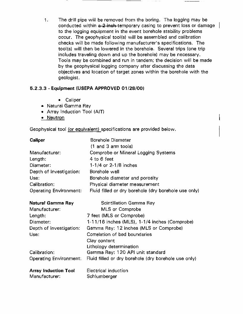
1. The drill pipe will be removed from the boring. The logging may beconducted within Q 2 inch temporary casing to prevent loss or damageto the logging equipment in the event borehole stability problemsoccur. The geophysical tool(s) will be assembled and calibrationchecks will be made following manufacturer's specifications. Thetool(s) will then be lowered in the borehole. Several trips (one tripincludes traveling down and up the borehole) may be necessary.Tools may be combined and run in tandem; the decision will be madeby the geophysical logging company after discussing the dataobjectives and location of target zones within the borehole with thegeologist.
5.2.3.3 - Equipment (USEPA APPROVED 01/28/00)
• Caliper• Natural Gamma Ray• Array Induction Tool (AIT)• Neutron
Geophysical tool (or equivalent) specifications are provided below.
Caliper
Manufacturer:Length:Diameter:Depth of Investigation:Use:Calibration:Operating Environment:
Natural Gamma RayManufacturer:Length:Diameter:Depth of Investigation:Use:
Calibration:Operating Environment:
Array Induction ToolManufacturer:
Borehole Diameter(1 and 3 arm tools)Comprobe or Mineral Logging Systems4 to 6 feet1-1/4 or 2-1/8 inchesBorehole wallBorehole diameter and porosityPhysical diameter measurementFluid filled or dry borehole (dry borehole use only)
Scintillation Gamma RayMLS or Comprobe
7 feet (MLS or Comprobe)1-11/16 inches (MLS), 1-1/4 inches (Comprobe)Gamma Ray: 12 inches (MLS or Comprobe)Correlation of bed boundariesClay contentLithology determinationGamma Ray: 120 API unit standardFluid filled or dry borehole (dry borehole use only)
Electrical inductionSchlumberger
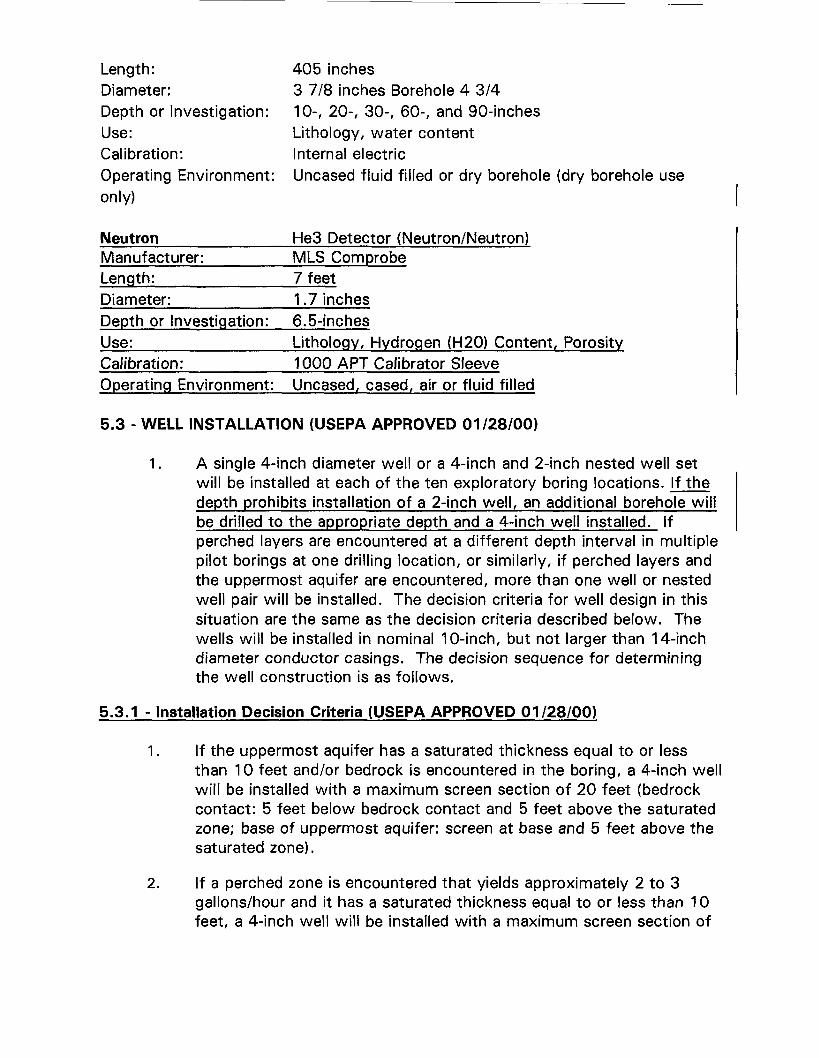
Length: 405 inchesDiameter: 3 7/8 inches Borehole 4 3/4Depth or Investigation: 10-, 20-, 30-, 60-, and 90-inchesUse: Lithology, water contentCalibration: Internal electricOperating Environment: Uncased fluid filled or dry borehole (dry borehole useonly)
NeutronManufacturer:Length:Diameter:Depth or Investigation:Use:Calibration:Operating Environment:
He3 Detector (Neutron/Neutron)MLS Comprobe7 feet1 .7 inches6.5-inchesLithology, Hydrogen (H20) Content, Porosity1 000 APT Calibrator SleeveUncased, cased, air or fluid filled
5.3 - WELL INSTALLATION {USEPA APPROVED 01/28/00}
1. A single 4-inch diameter well or a 4-inch and 2-inch nested well setwill be installed at each of the ten exploratory boring locations. If thedepth prohibits installation of a 2-inch well, an additional borehole willbe drilled to the appropriate depth and a 4-inch well installed. Ifperched layers are encountered at a different depth interval in multiplepilot borings at one drilling location, or similarly, if perched layers andthe uppermost aquifer are encountered, more than one well or nestedwell pair will be installed. The decision criteria for well design in thissituation are the same as the decision criteria described below. Thewells will be installed in nominal 10-inch, but not larger than 14-inchdiameter conductor casings. The decision sequence for determiningthe well construction is as follows.
5.3.1 - Installation Decision Criteria (USEPA APPROVED 01/28/00)
1. If the uppermost aquifer has a saturated thickness equal to or lessthan 10 feet and/or bedrock is encountered in the boring, a 4-inch wellwill be installed with a maximum screen section of 20 feet (bedrockcontact: 5 feet below bedrock contact and 5 feet above the saturatedzone; base of uppermost aquifer: screen at base and 5 feet above thesaturated zone).
2. If a perched zone is encountered that yields approximately 2 to 3gallons/hour and it has a saturated thickness equal to or less than 10feet, a 4-inch well will be installed with a maximum screen section of
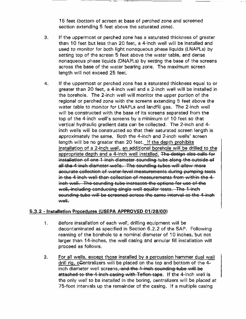
15 feet (bottom of screen at base of perched zone and screenedsection extending 5 feet above the saturated zone).
3. If the uppermost or perched zone has a saturated thickness of greaterthan 10 feet but less than 20 feet, a 4-inch well will be installed andused to monitor for both light nonaqueous phase liquids (LNAPLs) bysetting top of the screen 5 feet above the water table, and densenonaqueous phase liquids (DNAPLs) by setting the base of the screensacross the base of the water bearing zone. The maximum screenlength will not exceed 25 feet.
4. If the uppermost or perched zone has a saturated thickness equal to orgreater than 20 feet, a 4-inch well and a 2-inch well will be installed inthe borehole. The 2-inch well will monitor the upper portion of theregional or perched zone with the screens extending 5 feet above thewater table to monitor for LNAPLs and landfill gas. The 2-inch wellwill be constructed with the base of its screens separated from thetop of the 4-inch well's screens by a minimum of 10 feet so thatvertical hydraulic gradient data can be collected. The 2-inch and 4-inch wells will be constructed so that their saturated screen length isapproximately the same. Both the 4-inch and 2-inch wells' screenlength will be no greater than 20 feet. If the depth prohibitsinstallation of a 2-inch well, an additional borehole will be drilled to theappropriate depth and a 4-inch well installed. Tho design also calls forinstallation of ono 1 inch diamotor Bounding tubo along the outsido ofall the 4-inch diameter wells. The sounding tubos will allow moreaccurate collection of water level measurements during pumping testsin the 4-inch well than collection of measurements from within tho 4inch woll. Tho sounding tubo incroaoos tho options for use of thowell, including conducting single well aquifer tests. Tho 1 inchsounding tube will bo scroonod across the same interval as the A inch• B rs^llv v v 11«
5.3.2 - Installation Procedures (USEPA APPROVED 01/28/00)
1. Before installation of each well, drilling equipment will bedecontaminated as specified in Section 6.2.2 of the SAP. Followingreaming of the borehole to a nominal diameter of 10 inches, but notlarger than 14-inches, the well casing and annular fill installation willproceed as follows.
2. For all wells, except those installed by a percussion hammer dual walldrill rig, cGentralizers will be placed on the top and bottom of the 4-inch diameter well screens, and the 1 inch sounding tube will boattached to the 4 inch casing with Teflon tapo. If the 4-inch well isthe only well to be installed in the boring, centralizers will be placed at75-foot intervals up the remainder of the casing. If a multiple casing
completion is to be installed, no additional centralizers will be usedbecause they will interfere with the placement of the additional casing.
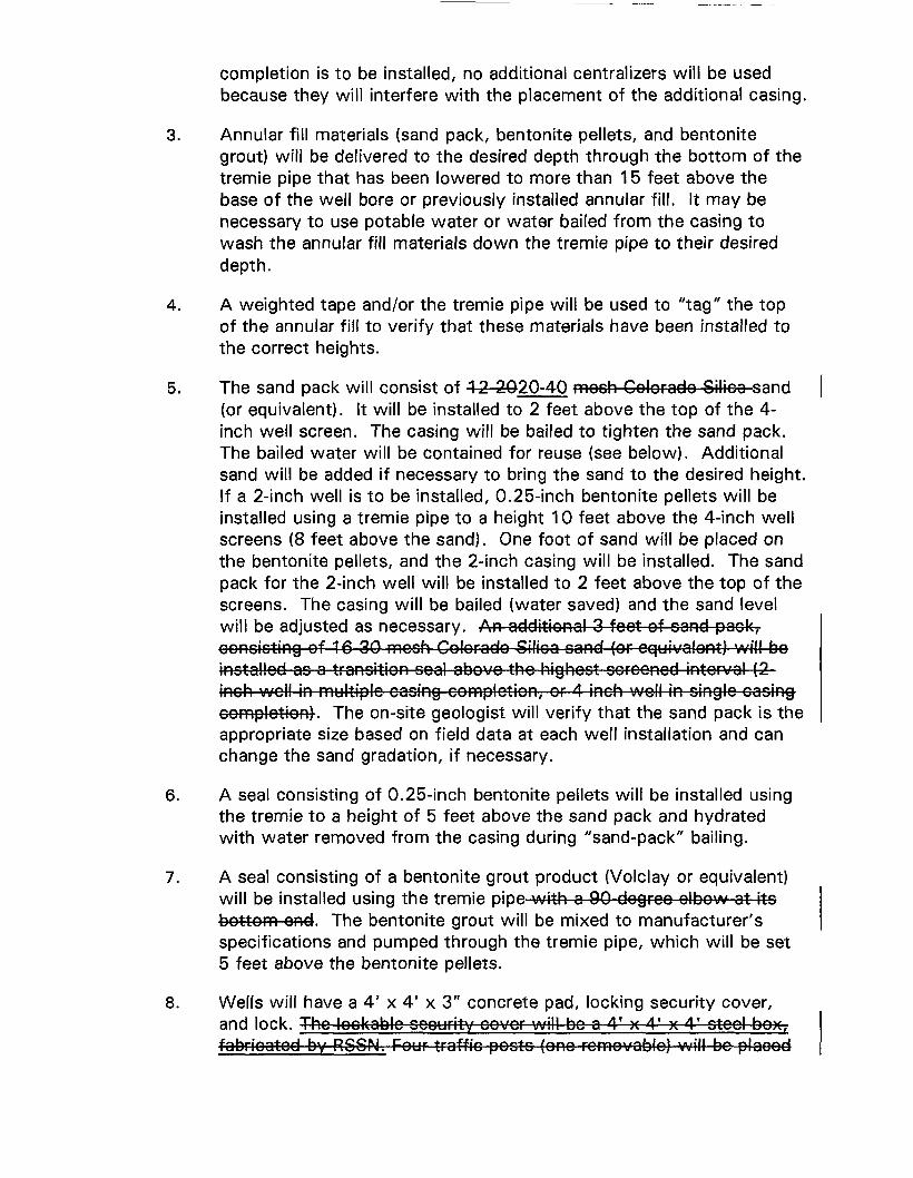
3. Annular fill materials (sand pack, bentonite pellets, and bentonitegrout) will be delivered to the desired depth through the bottom of thetremie pipe that has been lowered to more than 15 feet above thebase of the well bore or previously installed annular fill. It may benecessary to use potable water or water bailed from the casing towash the annular fill materials down the tremie pipe to their desireddepth.
4. A weighted tape and/or the tremie pipe will be used to "tag" the topof the annular fill to verify that these materials have been installed tothe correct heights.
5. The sand pack will consist of 12 2020-40 mosh Colorado Silica sand(or equivalent). It will be installed to 2 feet above the top of the 4-inch well screen. The casing will be bailed to tighten the sand pack.The bailed water will be contained for reuse (see below). Additionalsand will be added if necessary to bring the sand to the desired height.If a 2-inch well is to be installed, 0.25-inch bentonite pellets will beinstalled using a tremie pipe to a height 10 feet above the 4-inch wellscreens (8 feet above the sand). One foot of sand will be placed onthe bentonite pellets, and the 2-inch casing will be installed. The sandpack for the 2-inch well will be installed to 2 feet above the top of thescreens. The casing will be bailed (water saved) and the sand levelwill be adjusted as necessary. An additional 3 feet of sand pack,consisting of 16 30 mosh Colorado Silica sand (or equivalent) will boinstalled as a transition soal above tho highest screened interval (2inch woll in multiple caoing completion, or 4 inch woll in oinglo cosingcompletion). The on-site geologist will verify that the sand pack is theappropriate size based on field data at each well installation and canchange the sand gradation, if necessary.
6. A seal consisting of 0.25-inch bentonite pellets will be installed usingthe tremie to a height of 5 feet above the sand pack and hydratedwith water removed from the casing during "sand-pack" bailing.
7. A seal consisting of a bentonite grout product (Volclay or equivalent)will be installed using the tremie pipe with a 90-degree elbow at itsbottom end. The bentonite grout will be mixed to manufacturer'sspecifications and pumped through the tremie pipe, which will be set5 feet above the bentonite pellets.
8. Wells will have a 4' x 4' x 3" concrete pad, locking security cover,and lock. Tho lockable security covor will bo a 4' x 4' x 4' steel box,fabricated by RSSN. Four traffic posts (one removablo) will be placed
to protect each woll. The locations and elevations of the wells will besurveyed by a licensed surveyor, and shown on a scaled plot plan.
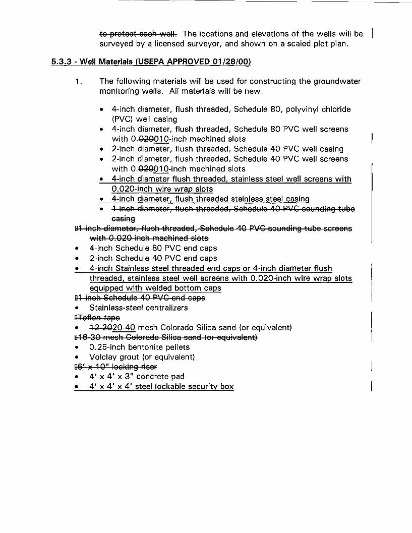
5.3.3 - Well Materials (USEPA APPROVED 01/28/00)
1 . The following materials will be used for constructing the groundwatermonitoring wells. All materials will be new.
• 4-inch diameter, flush threaded, Schedule 80, polyvinyl chloride(PVC) well casing
• 4-inch diameter, flush threaded, Schedule 80 PVC well screenswith 0.030010-inch machined slots
• 2-inch diameter, flush threaded, Schedule 40 PVC well casing• 2-inch diameter, flush threaded, Schedule 40 PVC well screens
with 0.03Q01 0-inch machined slots• 4-inch diameter flush threaded, stainless steel well screens with
0.020-inch wire wrap slots• 4-inch diameter, flush threaded stainless steel casing• 1 inch diomotor, flush threaded, Schedule 40 PVC sounding tubo
D1 inch diameter, flush threaded, Schedule 40 PVC sounding tubo screenswith 0.020 inch machined slots
• 4-inch Schedule 80 PVC end caps• 2-inch Schedule 40 PVC end caps• 4-inch Stainless steel threaded end caps or 4-inch diameter flush
threaded, stainless steel well screens with 0.020-inch wire wrap slotsequipped with welded bottom caps
01 inch Schedule 10 PVC ond cops• Stainless-steel centralizersDTeflon tapo• 1 2 2020-40 mesh Colorado Silica sand (or equivalent)G16 30 mesh Colorado Silica sand (or equivalent)• 0.25-inch bentonite pellets• Volclay grout (or equivalent)D6' x 10" locking riser• 4' x 4' x 3" concrete pad• 4' x 4' x 4' steel lockable security box