lumicheck plate and software user manual
TRANSCRIPT
Sample to Insight__
June 2017
LumiCheck Plate and Software User Manual For use with LumiCheck Plate Software versions 2.0.1, 2.0.2 and 2.0.3
6000-5013
QIAGEN 19300 Germantown Road Germantown, MD 20874 USA
QIAGEN GmBH QIAGEN Strasse 1 40724 Hilden GERMANY
L02002 Rev. 05

LumiCheck Plate and Software User Manual 06/2017 2
Trademarks: QIAGEN®, Sample to Insight®, digene®, HC2®, Hybrid Capture® (QIAGEN Group); Microsoft®, Windows® (Microsoft Corporation). Microsoft product screen shots are printed with permission from Microsoft Corporation. Registered names, trademarks, etc., used in this document, even when not specifically marked as such, are not to be considered unprotected by law.
The LumiCheck Plate, its components or its method of use may be covered by the following patent and its international counterpart: U.S. Patent No. 6,335,997
© 2014–2017 QIAGEN, all rights reserved.

LumiCheck Plate and Software User Manual 06/2017 3
Contents
1 Introduction .............................................................................................................7
1.1 General information ........................................................................................7
1.1.1 Technical assistance ................................................................................7
1.1.2 Version management ..............................................................................7
1.1.3 Software license agreement .....................................................................8
1.1.4 License grant ..........................................................................................8
1.1.5 Restrictions .............................................................................................8
1.1.6 Termination and transfer ..........................................................................8
1.1.7 Communication of license agreement ........................................................8
1.1.8 Unauthorized use and compliance ............................................................8
1.1.9 Warranty and special provisions ..............................................................9
1.1.10 Limitation of liability ................................................................................9
1.2 Intended use ..................................................................................................9
1.1.1 Requirements for users ...........................................................................10
1.2 Operating software.......................................................................................10
2 Safety Information ..................................................................................................13
2.1 Proper use ...................................................................................................13
2.2 Electrical safety ............................................................................................14
2.3 Waste disposal ............................................................................................14
2.4 Symbols ......................................................................................................15
3 Functional Description .............................................................................................17
3.1 Hardware components ..................................................................................17
3.1.1 Light-emitting wells ................................................................................18
3.1.2 Cross-talk light source ...........................................................................19
3.1.3 LumiCheck Plate battery.........................................................................19
3.1.4 Power switch ........................................................................................20
3.1.5 Activation switch ..................................................................................20
3.1.6 Battery test button .................................................................................20
3.2 LumiCheck Plate Software components ............................................................20
LumiCheck Plate and Software User Manual 06/2017 4
4 Installation .............................................................................................................22
4.1 Unpacking ...................................................................................................22
4.2 Installing the LumiCheck Plate software ............................................................22
4.3 Uninstalling the LumiCheck Plate Software .......................................................22
5 Software Features ...................................................................................................23
5.1 Using the Periodic Check tab ..........................................................................24
5.1.1 Using the Measurements dialog box .......................................................26
5.2 Using the Reports tab ....................................................................................27
5.3 Using the Trends tab .....................................................................................29
5.4 Using the Users tab .......................................................................................31
5.5 Using the Utilities/Settings tab........................................................................32
5.6 Using the Luminometer Settings tab ................................................................34
5.6.1 Using the Luminometer Settings tab with a DML 3000 ..............................35
5.6.2 Using the Luminometer Controls dialog box with a DML 3000 ...................37
5.6.3 Using the Luminometer Settings tab with a DML 2000 ..............................38
5.6.4 Using the Luminometer Controls dialog box with a DML 2000 ...................42
5.7 Using the QIAGEN Report Viewer window .......................................................44
6 General Operation .................................................................................................46
6.1 Logging in ...................................................................................................46
6.2 Modifying the laboratory header information ...................................................47
6.3 Managing users ...........................................................................................47
6.3.1 Adding users........................................................................................48
6.3.2 Editing users ........................................................................................49
6.3.3 Deleting a user .....................................................................................49
6.4 Managing the DML instrument ........................................................................49
6.4.1 Adding a DML instrument ......................................................................49
6.4.2 Modifying the settings of a DML instrument ..............................................51
6.4.3 Performing a mechanical test .................................................................51
6.4.4 Understanding the background baseline (100) reading .............................52
6.4.5 Performing a background baseline (100) reading ....................................52
6.4.6 Understanding the plate background (10) reading ...................................53

LumiCheck Plate and Software User Manual 06/2017 5
6.4.7 Establishing the iris factor ......................................................................53
6.4.8 Manually controlling the DML instrument .................................................54
6.4.9 Deleting a DML instrument .....................................................................54
6.5 Using the LumiCheck Plate .............................................................................55
6.5.1 Powering ON and OFF the LumiCheck Plate ............................................55
6.5.2 Checking the LumiCheck Plate battery .....................................................55
6.6 Managing master files ...................................................................................56
6.6.1 Taking measurements for a master file .....................................................56
6.6.2 Printing the measurements for a master file ..............................................57
6.6.3 Deleting the measurements for a master file .............................................58
6.6.4 Creating a master file from measurements ...............................................58
6.6.5 Deleting a master file ............................................................................59
6.7 Managing periodic checks ............................................................................60
6.7.1 Taking measurements for a periodic check ..............................................60
6.7.2 Printing the measurements for a periodic check ........................................61
6.7.3 Deleting the measurements for a periodic check .......................................62
6.7.4 Analyzing a periodic check ...................................................................62
6.7.5 Deleting a periodic check ......................................................................63
6.8 Viewing reports ............................................................................................63
6.8.1 Understanding the LumiCheck periodic master set values report .................65
6.8.2 Understanding the LumiCheck periodic test report .....................................67
6.8.3 Understanding the iris factor analysis report ............................................71
6.9 Generating trending reports ...........................................................................72
6.9.1 Understanding the periodic check trending report.....................................73
6.9.2 Understanding the background baseline (100) trending report ...................76
6.9.3 Understanding the plate background (10) trending report .........................77
6.10 Importing and exporting data ....................................................................78
6.10.1 Exporting data .....................................................................................78
6.10.2 Importing data .....................................................................................78
6.11 Archiving data .........................................................................................79
6.11.1 Viewing archived data ..........................................................................80

LumiCheck Plate and Software User Manual 06/2017 6
7 Maintenance .........................................................................................................81
7.1 Routine cleaning ...........................................................................................81
7.2 Calibration ..................................................................................................81
7.3 Replacing the LumiCheck Plate battery ............................................................82
7.4 Disposing of the LumiCheck Plate battery .........................................................82
8 Troubleshooting .....................................................................................................83
8.1 Master file or periodic check fails ...................................................................83
8.2 Periodic check measurement fails ...................................................................84
8.3 Software messages .......................................................................................87
Ordering Information ........................................................................................................88
Appendix A — Technical Data ...........................................................................................89
Appendix B — Waste Electrical and Electronic Equipment (WEEE) .........................................91
Index ..............................................................................................................................92

LumiCheck Plate and Software User Manual 06/2017 7
1 Introduction
Thank you for choosing the LumiCheck Plate. We are confident it will become an integral part of
your laboratory.
Before using the instrument, it is essential that you read this user manual carefully and pay
particular attention to the safety information. The instructions and safety information in the user
manual must be followed to ensure safe operation of the instrument and to maintain the instrument
in a safe condition.
1.1 General information
This user manual provides instructions on using the LumiCheck Plate and associated software as a
tool to monitor the performance of the digene® microplate luminometer (DML) instruments. Use this
user manual, along with the other user manuals provided, as part of the digene Hybrid
Capture® 2 (HC2®) System Suite.
1.1.1 Technical assistance
At QIAGEN we pride ourselves on the quality and availability of our technical support. If you
have any questions or experience any difficulties regarding the instrument or QIAGEN products in
general, do not hesitate to contact us.
QIAGEN customers are a valuable source of information regarding our products. We encourage
you to contact us if you have any suggestions or feedback concerning our products.
For technical assistance and more information, contact QIAGEN Technical Services or a local
distributor.
1.1.2 Version management
This document is LumiCheck Plate and Software User Manual, L02002, Rev. 04. This user manual
is for use with LumiCheck Plate Software versions 2.0.1, 2.0.2 and 2.0.3 and digene HC2 DNA
tests as part of digene HC2 System Suite.

LumiCheck Plate and Software User Manual 06/2017 8
1.1.3 Software license agreement
This software license agreement applies only to the LumiCheck Plate Software provided as part of
the digene HC2 System Suite. The license agreement sets forth the terms and conditions of the
license and the limited warranty for the LumiCheck Plate.
1.1.4 License grant
The customer does not receive title to the LumiCheck Plate Software. The customer is granted a
nonexclusive license to use the LumiCheck Plate Software subject to the restrictions and terms set
forth in this agreement.
1.1.5 Restrictions
An installed copy of the LumiCheck Plate Software may not be used on multiple computers
through file serving, networking or communications packages. The LumiCheck Plate Software may
not be rented, loaned or leased. The LumiCheck Plate Software or accompanying documentation
may not be copied, except as specifically permitted in this license agreement. Proprietary notices,
labels or marks on the LumiCheck Plate Software or accompanying documentation may not be
removed or altered. The LumiCheck Plate Software or accompanying documentation may not be
modified, translated, reverse engineered, disassembled or decompiled.
1.1.6 Termination and transfer
Any failure to comply with the terms and conditions of this agreement will result in automatic
termination of this license. Upon termination of this license for any reason, the customer must
destroy all copies of the LumiCheck Plate Software and accompanying documentation. The
customer may not transfer the LumiCheck Plate Software without prior written agreement.
1.1.7 Communication of license agreement
The customer agrees to communicate the terms and restrictions contained in this license
agreement to all persons under his or her employment, direction or control.
1.1.8 Unauthorized use and compliance
The customer will use all reasonable efforts to see that employees, agents, assignees or other
persons under the direction and control of the customer abide by terms and conditions of this
license agreement.

LumiCheck Plate and Software User Manual 06/2017 9
1.1.9 Warranty and special provisions
QIAGEN warrants that the LumiCheck Plate Software will perform in accordance with the
accompanying written materials for a period of 90 days from the date of receipt. Any implied
warranties on the LumiCheck Plate Software are limited to 90 days. Some countries, states or
jurisdictions do not allow limitations on duration of an implied warranty.
The warranty of the LumiCheck Plate is 12 months from the date of shipment, excluding the
battery.
1.1.10 Limitation of liability
Notwithstanding anything to the contrary contained herein, the liability of the seller (whether by
reason of breach of warranty, breach of contract, tort or otherwise), including without limitation
under any indemnification provision contained herein, shall be limited to replacement of goods
returned to QIAGEN which are shown to reasonable satisfaction to QIAGEN to have been
nonconforming or to refund the purchase price, or, if not paid, to a credit amount of the purchase
price thereof.
The foregoing warranties are exclusive and are given and accepted in lieu of any and all other
warranties, expressed or implied, including without limitation, the implied warranty of
merchantability and the implied warranty of fitness for a particular purpose. Neither party shall
be liable to the other for any incidental, indirect, special or consequential damages.
1.2 Intended use
The LumiCheck Plate is intended to monitor the performance consistency of the DML instrument
through periodic testing of the following:
Absolute relative light units (RLU)
Relative linearity over the dynamic range of the DML instrument
Background stability
Cross‐talk
The LumiCheck Plate establishes a set of specifications for a specific DML instrument. Based on the
established specifications, the LumiCheck Plate is used to monitor the stability of the DML
instrument.
The LumiCheck Plate is used as an early warning of potential DML instrument failure and as a
diagnostic tool in the event of a failed digene HC2 DNA test. A failed periodic check using the

LumiCheck Plate and Software User Manual 06/2017 10
LumiCheck Plate does not invalidate prior assay results as each digene HC2 DNA test contains
internal verification criteria that validate the assay.
1.1.1 Requirements for users
The table below shows the level of training and experience required for transportation,
installation, use, maintenance and servicing of the instrument.
Type of task Personnel Training and experience
Transportation Approved carrier Appropriately trained, experienced and approved by QIAGEN
Installation Laboratory technicians or equivalent
Appropriately trained, experienced, and familiar with the use of computers and automation in general
Routine use Laboratory technicians or equivalent
Appropriately trained, experienced, and familiar with the use of computers and automation in general
Maintenance Laboratory technicians or equivalent
Appropriately trained, experienced, and familiar with the use of computers and automation in general
Service QIAGEN Field Service employees or personnel trained by QIAGEN
Trained, certified and authorized by QIAGEN
1.2 Operating software
Users must be familiar with the use of computers to initiate instrument functions, such as to activate
or halt automated functions and to retrieve stored data.
LumiCheck Plate and Software User Manual 06/2017 11
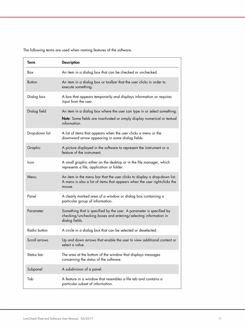
The following terms are used when naming features of the software.
Term Description
Box An item in a dialog box that can be checked or unchecked.
Button An item in a dialog box or toolbar that the user clicks in order to execute something.
Dialog box A box that appears temporarily and displays information or requires input from the user.
Dialog field An item in a dialog box where the user can type in or select something.
Note: Some fields are inactivated or simply display numerical or textual information.
Drop-down list A list of items that appears when the user clicks a menu or the downward arrow appearing in some dialog fields.
Graphic A picture displayed in the software to represent the instrument or a feature of the instrument.
Icon A small graphic either on the desktop or in the file manager, which represents a file, application or folder.
Menu An item in the menu bar that the user clicks to display a drop-down list. A menu is also a list of items that appears when the user right-clicks the mouse.
Panel A clearly marked area of a window or dialog box containing a particular group of information.
Parameter Something that is specified by the user. A parameter is specified by checking/unchecking boxes and entering/selecting information in dialog fields.
Radio button A circle in a dialog box that can be selected or deselected.
Scroll arrows Up and down arrows that enable the user to view additional content or select a value.
Status bar The area at the bottom of the window that displays messages concerning the status of the software.
Subpanel A subdivision of a panel.
Tab A feature in a window that resembles a file tab and contains a particular subset of information.
LumiCheck Plate and Software User Manual 06/2017 12
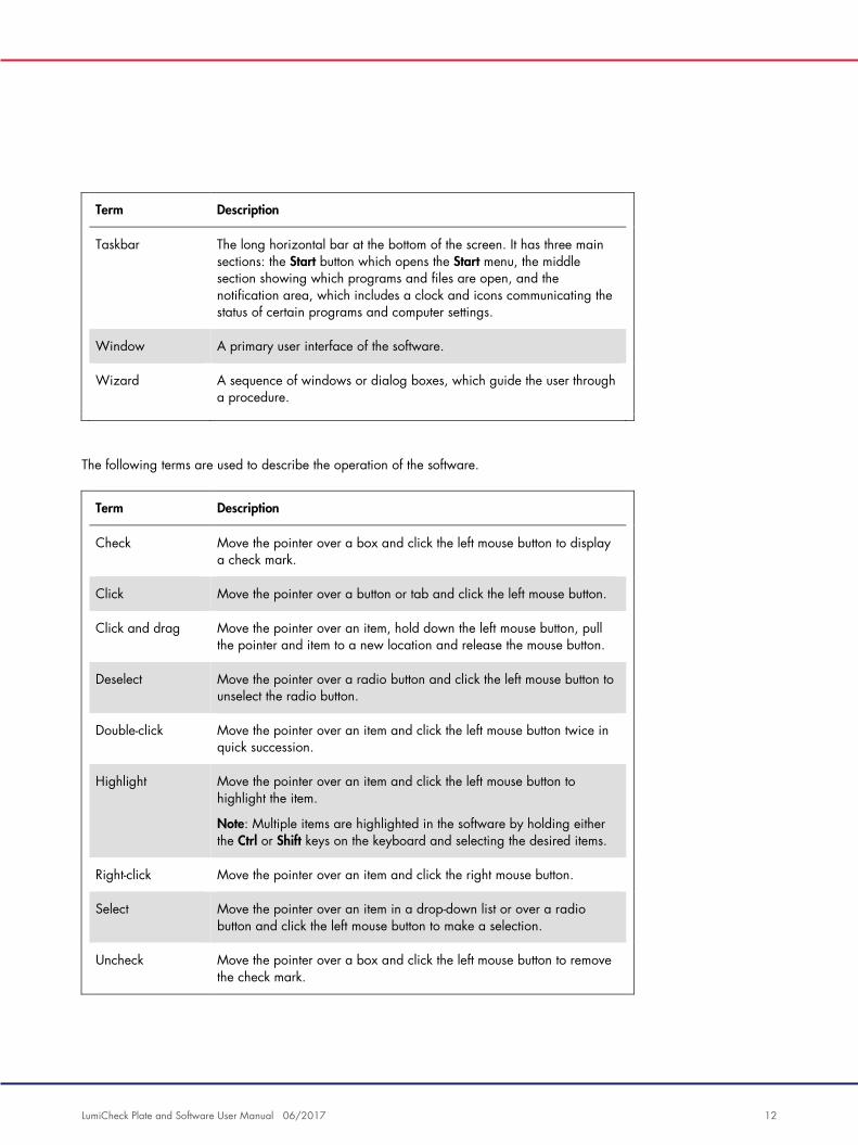
Term Description
Taskbar The long horizontal bar at the bottom of the screen. It has three main sections: the Start button which opens the Start menu, the middle section showing which programs and files are open, and the notification area, which includes a clock and icons communicating the status of certain programs and computer settings.
Window A primary user interface of the software.
Wizard A sequence of windows or dialog boxes, which guide the user through a procedure.
The following terms are used to describe the operation of the software.
Term Description
Check Move the pointer over a box and click the left mouse button to display a check mark.
Click Move the pointer over a button or tab and click the left mouse button.
Click and drag Move the pointer over an item, hold down the left mouse button, pull the pointer and item to a new location and release the mouse button.
Deselect Move the pointer over a radio button and click the left mouse button to unselect the radio button.
Double-click Move the pointer over an item and click the left mouse button twice in quick succession.
Highlight Move the pointer over an item and click the left mouse button to highlight the item.
Note: Multiple items are highlighted in the software by holding either the Ctrl or Shift keys on the keyboard and selecting the desired items.
Right-click Move the pointer over an item and click the right mouse button.
Select Move the pointer over an item in a drop-down list or over a radio button and click the left mouse button to make a selection.
Uncheck Move the pointer over a box and click the left mouse button to remove the check mark.

LumiCheck Plate and Software User Manual 06/2017 13
2 Safety Information
This user manual contains information about warnings and cautions that users must follow to
ensure safe operation of the software and the instrument and to maintain the instrument in a safe
condition.
The following types of safety information appear in this user manual.
WARNING
The term WARNING is used to inform you about situations that could result in
personal injury to you or others.
Details about these circumstances are provided to avoid personal injury to you
or other persons.
CAUTION
The term CAUTION is used to inform you about situations that could result in
damage to the instrument or other equipment.
Details about these circumstances are provided to avoid damage to the
instrument or other equipment.
Before using the instrument, it is essential to read this user manual carefully and to pay particular
attention to any instructions it contains concerning hazards that may arise from the use of the
instrument.
The guidance given in this manual is intended to supplement, not supersede, the normal safety
requirements prevailing in your country.
2.1 Proper use
WARNING/
CAUTION
Risk of personal injury and material damage
Improper use of the LumiCheck Plate may cause personal injuries to the user or
damage the LumiCheck Plate.
The LumiCheck Plate must be used only in conjunction with the DML instrument
and must only be operated by qualified personnel who have been
appropriately trained.

LumiCheck Plate and Software User Manual 06/2017 14
CAUTION
Damage to the instrument
The activation switch and battery test button are fragile parts. Handle with care
and pay attention to prevent damage to these parts.
CAUTION
Damage to the instrument
Do not immerse the LumiCheck Plate in water or allow water to enter the
chamber of the LumiCheck Plate.
CAUTION
Risk of personal injury or incorrect results
Do not operate the LumiCheck Plate with the battery cover removed or without
all the cover fasteners in place.
CAUTION
Damage to the instrument
To properly protect from damage during transport, only transport the
LumiCheck Plate in the manufacturer’s original packaging.
2.2 Electrical safety
When not in use, power OFF the LumiCheck Plate.
Avoid allowing the LumiCheck Plate to come into contact with liquids.
Do not attempt to disassemble the LumiCheck Plate.
The HC2 System hardware components are equipped with alternating current (AC) power cords
that, when connected to the applicable AC power outlet, ground the instruments. Do not operate
any HC2 System component from an AC power outlet that has no ground connection.
Refer to the applicable user manual for additional safety information.
2.3 Waste disposal
To dispose of the LumiCheck Plate, follow all national, state and local health and safety regulation
and laws for disposing of laboratory waste. For disposal of Waste Electrical and Electronic

LumiCheck Plate and Software User Manual 06/2017 15
Equipment (WEEE compliance), see “Appendix B — Waste Electrical and Electronic Equipment
(WEEE),” page 91.
2.4 Symbols
The following symbols may be found on the instrument, in this user manual or on labels
associated with the instrument.
Symbol Location Description
On the instrument Catalog number
On the instrument Serial number
On the instrument Consult instructions for use
On the instrument CE mark for Europe
On the instrument In vitro diagnostic medical device
On the instrument Waste Electrical and Electronic Equipment
(WEEE)
On the instrument Manufacturer
In this user manual Authorized representative in the European
Community

LumiCheck Plate and Software User Manual 06/2017 16
Symbol Location Description
On the instrument Indicates the battery test button
On the instrument Indicates the activation switch

LumiCheck Plate and Software User Manual 06/2017 17
3 Functional Description
The LumiCheck Plate is designed to monitor the performance of the DML instrument over time.
Light derived from the light‐emitting diode (LED) sources is emitted at a dynamic range that
extends over 6 decades. An internal circuit within the LumiCheck Plate stabilizes the internal
lights. The measurement of the 8 LED wells of the LumiCheck Plate using a DML instrument
establishes a set of specifications in the form of a master file.
Once a master file is established, a periodic check is performed by measuring the LumiCheck
Plate using the DML instrument. During a periodic check, all the wells of the LumiCheck Plate are
measured, including the wells that do not emit light. The LumiCheck Plate Software analyzes the
data from the measurement and verifies that the data meet the specification criteria.
3.1 Hardware components
Top of the LumiCheck Plate:
Light-emitting wells (A1–A8) Cross-talk light source
Cross-talk wells (A9 and B8)
1
2
3
LumiCheck Plate and Software User Manual 06/2017 18
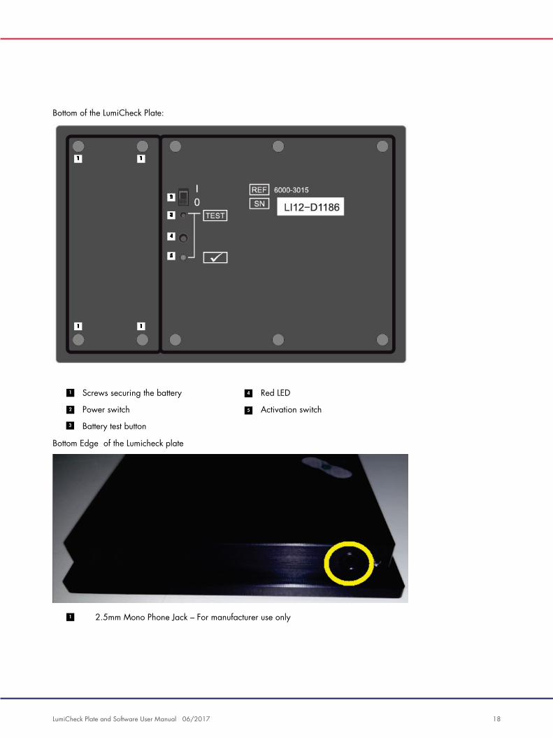
Bottom of the LumiCheck Plate:
Screws securing the battery Red LED
Power switch Activation switch
Battery test button
Bottom Edge of the Lumicheck plate
2.5mm Mono Phone Jack – For manufacturer use only
1
2
3
4
5
1
LumiCheck Plate and Software User Manual 06/2017 19
3.1.1 Light-emitting wells
The LumiCheck Plate has 8 wells that mimic the light emitted during plate measurement. The wells
are A1 through A8 and increase in light output as the numerical value increases. The light of the
wells is produced from 2 LED lights with one LED light providing the light for wells A1 through A7
and the second LED light providing the light for well A8. The light-emitting wells are used during
the plate measurement of the LumiCheck Plate.
3.1.2 Cross-talk light source
Cross‐talk is excessive light emitted from neighboring microplate wells that contributes to an
artificially higher RLU result in the well that is being measured. The DML instrument, when used
with the correct microplates, reduces or eliminates cross‐talk by using a specialized optical
pathway in combination with a plate mask that holds the microplate securely in place during
measurement. The correct alignment of the plate mask and plate carrier is essential to minimize
cross‐talk.
The LumiCheck Plate includes a cross-talk light source that emits light between wells A9 and B8.
The measurements of wells A9 and B8 are used to determine if cross-talk is within specification.
During a periodic check, all wells of the LumiCheck Plate are measured. The LumiCheck Plate
Software calculates cross‐talk by dividing the highest RLU value from either well A9 or well B8 by
the RLU value of well A8 and multiplying that result by 100,000. Cross‐talk is calculated as
RLU per 1 x 10⁵ RLU.
3.1.3 LumiCheck Plate battery
The LumiCheck Plate is powered by a replaceable battery. The LumiCheck Plate battery is
estimated to operate for approximately 4–6 months based on the average use of 5 minutes per
day for 5 days per week. The battery life is dependent on the amount of time the LumiCheck Plate
is powered ON and the frequency of use. When stored at room temperature, the LumiCheck Plate
battery loses approximately 5% power capacity per year. Under ideal storage conditions, the
expected shelf life of the LumiCheck Plate battery is at least 5 years.
The battery life will decrease if the LumiCheck Plate is powered ON for more than the few minutes
required to perform measurement. Make sure to power OFF the LumiCheck Plate when not in use.

LumiCheck Plate and Software User Manual 06/2017 20
Before using the LumiCheck Plate, check the battery. See “Checking the LumiCheck Plate battery,”
page 55, for additional instructions. As an indication that the battery power is failing, the
LumiCheck Plate cuts power to the A8 well when the battery voltage is less than 4.7 volts.
During replacement of the battery, remove only the screws that secure the LumiCheck Plate
battery. See “Replacing the LumiCheck Plate battery,” page 82, for additional instructions.
Replacement batteries for the LumiCheck Plate are available from QIAGEN.
3.1.4 Power switch
The power switch is used to power ON and power OFF the LumiCheck Plate. The light-emitting
wells are activated when the LumiCheck plate is powered ON. See “Powering ON and OFF the
LumiCheck Plate,” page 55, for additional instructions.
3.1.5 Activation switch
The activation switch controls the illumination of the light-emitting wells of the LumiCheck Plate.
When loaded in the DML instrument, the activation switch is automatically pressed. While
powered ON and loaded in the DML instrument, the light-emitting wells illuminate.
3.1.6 Battery test button
The battery test button is used to confirm the LumiCheck Plate battery has sufficient power and is
not failing. When the activation switch and the test button are pressed, the red LED light on the
back of the LumiCheck Plate is illuminated. See “Checking the LumiCheck Plate battery,”
page 55, for additional instructions.
3.1.7 2.5 mm mono phone jack
The 2.5 mm mono phone jack is reserved for manufacturer use only.
3.2 LumiCheck Plate Software components
The LumiCheck Plate Software is supplied on the HC2 System computer and runs using the
Microsoft® Windows® XP operating system (for LumiCheck versions 2.0.1 and 2.0.2) or
Windows 7 operating system (for LumiCheck version 2.0.3). The LumiCheck Plate Software works
in conjunction with the DML instrument.

LumiCheck Plate and Software User Manual 06/2017 21
The LumiCheck Plate has been tested in the environment of the supplied software applications.
Installation of additional programs or connecting the HC2 System computer to the internet may
adversely interact with the LumiCheck Software and cause it to be inoperable. Accordingly,
installation of programs not provided by QIAGEN on the HC2 System computer may render the
LumiCheck Plate Software inoperable. Installation of additional software or connecting the HC2
System computer to the internet voids all warranties.

LumiCheck Plate and Software User Manual 06/2017 22
4 Installation
4.1 Unpacking
Before using the LumiCheck Plate for the first time, examine the exterior carton and the instrument
itself for damage. In the event of shipping damage, contact your local QIAGEN representative or
QIAGEN Technical Services.
The LumiCheck Plate is shipped in a cardboard box. When received, open the cardboard box
and remove the black storage case. Open the black storage case and confirm all the components
of the LumiCheck Plate are included.
The package should contain the following components:
A black storage case
A LumiCheck Plate
A battery test tool
A screwdriver
A replacement pack containing 4 screws, a battery test tool and a battery
4.2 Installing the LumiCheck Plate software
The HC2 System computer should arrive with the LumiCheck Plate Software installed. Refer to the
instructions in digene HC2 System Software User Manual if the installation of the LumiCheck Plate
Software is required for some other reason.
The LumiCheck Plate Software requires a minimum of 50 megabytes of free hard disk space.
4.3 Uninstalling the LumiCheck Plate Software
As a component of the digene HC2 System Suite, the LumiCheck Plate Software cannot be
uninstalled separately from the digene HC2 System Suite. To uninstall the LumiCheck Plate
Software, refer to digene HC2 System Software User Manual for additional instructions.

LumiCheck Plate and Software User Manual 06/2017 23
5 Software Features
The LumiCheck Plate Software contains a series of tabs that display across the top of the software
window. The Periodic Check tab is foremost when the LumiCheck Plate Software is started and
when a user logs in. The footer of the window remains constant.
The window header provides the following functions:
Feature Function
Current luminometer: dialog box
Displays the serial number of the DML instrument selected to perform measurement.
Current user: dialog box Displays the user ID of the current user logged in to the LumiCheck Plate Software.
Change User… button Opens the User Login dialog box.
A new user must log in.
About… button Opens the About QIAGEN Microplate System dialog box.
The version and copyright information for the LumiCheck Plate Software is displayed.
Exit button Opens the exit dialog box.
Click Yes to exit the LumiCheck Plate Software or No to keep the LumiCheck Plate Software open.

LumiCheck Plate and Software User Manual 06/2017 24
5.1 Using the Periodic Check tab
The Periodic Check tab is used to create, modify and manage data files, master files and periodic
checks.
Example of the Periodic Check tab:
The Master Files panel lists the master files that have been created for the LumiCheck Plate and
DML instrument combination selected in the drop-down lists. The Periodic Measurements panel lists
the periodic checks that have been completed for the LumiCheck Plate and DML instrument
combination selected in the drop-down lists. Select <All> in the Plate SN: and Lum SN: drop-down
lists to see all master files and periodic measurements.
The data displayed in the Master Files and Periodic Measurements panels can be sorted by
selecting the applicable heading in the respective panel.

LumiCheck Plate and Software User Manual 06/2017 25
The following table describes the actions that can be performed in the Periodic Check tab.
To... Click or select...
see the master files and periodic checks associated with a LumiCheck Plate
the LumiCheck Plate serial number from the Plate SN: drop-down list.
see the master files and periodic checks associated with a DML instrument
the DML instrument serial number from the Lum SN: drop-down list.
manage the measurements for master files
the Measurements… button in the Master Files panel. The Measurements dialog box opens.
See “Using the Measurements dialog box,” page 26, for additional instructions.
create a master file the Create Master… button in the Master Files panel. The Master File Data Analysis dialog box opens.
See “Creating a master file from measurements,” page 58, for additional information.
delete a master file the master file from the list in the Master Files panel and click the Delete button.
See “Deleting a master file,” page 59, for additional instructions.
manage the measurements for periodic checks
the Measurements… button in the Periodic Measurements panel. The Measurements dialog box opens.
See “Using the Measurements dialog box,” page 26, for additional instructions.
analyze the data of a periodic check
the Analyze… button in the Periodic Measurements panel.
See “Analyzing a periodic check,” page 62, for additional instructions.
delete the measurements for a periodic check
the data file from the list in the Periodic Measurements panel and click the Delete button.
See “Deleting the measurements for a periodic check,” page 62, for additional instructions.

LumiCheck Plate and Software User Manual 06/2017 26
5.1.1 Using the Measurements dialog box
The Measurements dialog box is used to manage the measurements for both master files and
periodic checks. The Measurements dialog box is accessed by clicking the Measurements…
button on the Periodic Check tab. The Measurements… button is located in both the Master Files
and Periodic Measurements panels of the Periodic Check tab.
Example of the Measurements dialog box:
The following table describes the actions that can be performed in the Measurements dialog box.
To... Click or select...
take measurements for a master file or periodic check
the New… button.
See “Taking measurements for a master file,” page 56, and “Taking measurements for a periodic check,” page 60, for additional instructions.
delete the measurements for a master file or a periodic check
the data file from the list and click the Delete button.
See “Deleting the measurements for a master file,” page 58, and “Deleting the measurements for a periodic check,” page 62, for additional instructions.
import a data file the Import button.
See “Importing data,” page 78, for additional instructions.
export a data file the data file from the list and click the Export button.
See “Exporting data,” page 78, for additional instructions.

LumiCheck Plate and Software User Manual 06/2017 27
To... Click or select...
print the data file the data file from the list and click the Print button.
See “Printing the measurements for a master file,” page 57, and “Printing the measurements for a periodic check,” page 61, for additional instructions.
close the Measurements dialog box
the Close button
5.2 Using the Reports tab
The Reports tab is used to generate reports. See “Viewing reports,” page 63, for additional
instructions.
Example of the Reports tab with a DML 3000 selected as the DML instrument:

LumiCheck Plate and Software User Manual 06/2017 28
Example of the Reports tab with a DML 2000 selected as the DML instrument:
The following table describes the actions that can be performed in the Reports tab.
To... Click or select...
specify the type of data for the report
the Periodic Master, Periodic Checks or Iris Factor Analyses radio button.
Note: The Iris Factor Analyses radio button is only available for a DML 2000.
specify the status of the report
the All, Passed or Failed radio button in the Show panel.
delete a master file or a periodic check
the data file in the list and click the Delete button.
See “Deleting a master file,” page 59, or “Deleting a periodic check“, page 63, for additional instructions.
generate a report with the parameters selected
the Show… button. The QIAGEN Report Viewer window opens.
See “Using the QIAGEN Report Viewer window,” page 44, for additional instructions.

LumiCheck Plate and Software User Manual 06/2017 29
5.3 Using the Trends tab
The Trends tab is used to view trending data based on the database maintained by the
LumiCheck Plate Software. The trend reports for background measurements are only available for
the DML 2000.
To generate trend reports, see “Generating trending reports,” page 72, for additional
instructions.
Example of the Trends tab with a DML 3000 selected as the DML instrument:

LumiCheck Plate and Software User Manual 06/2017 30
Example of the Trends tab with a DML 2000 selected as the DML instrument:
The following table describes the actions that can be performed in the Trends tab.
To... Click or select...
specify the type of data for the trend report
the applicable radio button.
Note: The only option for a DML 3000 is the Periodic Ratios radio button.
specify a date range for the trend report
the applicable parameters in the Start Date: and End Date: dialog fields in the Trend Range panel.
generate a trending report with the parameters selected
the Trend… button. The QIAGEN Report Viewer window opens.
See “Using the QIAGEN Report Viewer window,” page 44, for additional instructions.

LumiCheck Plate and Software User Manual 06/2017 31
5.4 Using the Users tab
The Users tab is used to modify user IDs, passwords and access levels. The Users tab only
displays if a user has supervisor access level. See “Managing users,” page 47, for additional
instructions.
Example of the Users tab:
The following table describes the actions that can be performed on the Users tab.
To... Click or select...
add a user the New… button. The ID Entry dialog box opens.
See “Adding users,” page 48, for additional instructions.
modify the password or access level of a user
the user ID from the list and click the Edit… button. The Edit User dialog box opens.
See “Editing users,” page 49, for additional instructions.

LumiCheck Plate and Software User Manual 06/2017 32
To... Click or select...
delete a user the user ID from the list and click the Delete button.
See “Deleting a user,” page 49, for additional instructions.
Note: At least one supervisor ID is required.
5.5 Using the Utilities/Settings tab
The Utilities/Settings tab is used to modify the laboratory name and header information, to
archive data and to establish the iris factor.
Example of the Utilities/Settings tab with a DML 3000 selected as the DML instrument:

LumiCheck Plate and Software User Manual 06/2017 33
Example of the Utilities/Settings tab with a DML 2000 selected as the DML instrument:
The following table describes the actions that can be performed on the Utilities/Settings tab.
To... Click or select...
modify the laboratory and header information
the Change… button in the Laboratory panel. The Edit Laboratory Information dialog box opens.
See “Modifying the laboratory header information,” page 47, for additional instructions.
perform an archive the Archive Data… button in the Archiving panel. The Archive Data dialog box opens.
See “Archiving data,” page 79, for additional instructions.
Note: Only users with supervisor access level may perform this function.

LumiCheck Plate and Software User Manual 06/2017 34
To... Click or select...
view an archive the View Archive Data… button in the Archiving panel. The View Archive Data dialog box opens.
See “Viewing archived data,” page 80, for additional instructions.
Note: Only users with supervisor access level may perform this function.
restore the current data to the trend database
the Restore Current Data button in the Archiving panel.
See “Viewing archived data,” page 80, for additional instructions.
Notes:
Only users with supervisor access level may perform this
function.
If not currently viewing an archive, the Restore Current
Data button is grayed-out.
establish the iris factor the Iris Factor… button. The New Iris Factor dialog box opens.
See “Establishing the iris factor,” page 53, for additional instructions.
Note: This function only applies to the DML 2000 and the Iris Factor… button will not appear if a DML 3000 is selected as the DML instrument.
5.6 Using the Luminometer Settings tab
The Luminometer Settings tab is used to manage the settings for the DML instruments, to perform
DML instrument diagnostic tests and to test the connection between the HC2 System computer and
the DML instrument. See “Managing the DML instrument,” page 49, for additional instructions.

LumiCheck Plate and Software User Manual 06/2017 35
5.6.1 Using the Luminometer Settings tab with a DML 3000
Example of the Luminometer Settings tab for the DML 3000:
The following table describes the actions that can be performed on the Luminometer Settings tab
when a DML 3000 is selected.
To... Click or select...
change the current DML instrument used to measure a plate
the DML instrument serial number from the drop-down list in the Luminometer Selection panel.
add a new DML instrument the Add Luminometer button in the Luminometer Selection panel. The Luminometer Settings dialog box opens.
See “Adding a DML instrument,” page 49, for additional instructions.

LumiCheck Plate and Software User Manual 06/2017 36
To... Click or select...
delete a DML instrument the DML instrument serial number from the drop-down list in the Luminometer Selection panel and click the Remove Luminometer button.
See “Deleting a DML instrument,” page 54, for additional instructions.
set the LumiCheck Plate Software to perform a mechanical test of the DML instrument automatically when a user logs in or a user is changed
the DML instrument serial number from the drop-down list in the Luminometer Selection panel and check the Perform mechanical test on startup box in the Mechanical Test Settings panel.
See “Performing a mechanical test,” page 51, for additional instructions.
display the results of the mechanical test immediately after the mechanical test is complete
the DML instrument serial number from the drop-down list in the Luminometer Selection panel and check the Display mechanical report after completion box in the Mechanical Test Settings panel.
See “Performing a mechanical test,” page 51, for additional instructions.
modify the settings of a DML the DML instrument serial number from the drop-down list in the Luminometer Selection panel and click the Settings… button.
See “Modifying the settings of a DML instrument,” page 51, for additional instructions.
perform a mechanical test the DML instrument serial number from the drop-down list in the Luminometer Selection panel and click the Perform Mechanical Test button in the Luminometer Actions panel.
See “Performing a mechanical test,” page 51, for additional instructions.
manually control the DML instrument
the DML instrument serial number from the drop-down list in the Luminometer Selection panel and click the Luminometer Controls… button in the Luminometer Actions panel.
See “Manually controlling the DML instrument,” page 54, for additional instructions.

LumiCheck Plate and Software User Manual 06/2017 37
5.6.2 Using the Luminometer Controls dialog box with a DML 3000
The DML 3000 can be manually controlled to determine if the instrument is functioning correctly.
The DML 3000 is controlled using the Luminometer Controls dialog box. The Luminometer
Controls dialog box is accessed on the Luminometer Settings tab by selecting the DML instrument
from the Luminometer Selection drop-down list and clicking the Luminometer Controls… button.
Example of the Luminometer Controls dialog box for the DML 3000:
The following table describes the actions that can be performed in the Luminometer Controls
dialog window when a DML 3000 is selected.
To... Click or select...
get the status of the DML instrument
the Get Status button.
The information in the Luminometer Controls dialog window will update on the current status of the DML instrument.
move the plate carrier to the home position
the Move Home button.
measure a specified well location
the specific location on the plate using the drop-down lists and click the Read Well button. The RLU result displays in the dialog field below the drop-down lists.
turn off the stepper motor for the plate carrier
the Motor Off button.
close the Luminometer Controls dialog box
the Close button.

LumiCheck Plate and Software User Manual 06/2017 38
The following table describes the features that are available in the Luminometer Controls dialog
box when a DML 3000 is selected.
Feature Function
Door Closed box If this box is checked, the door was closed during the last status check of the DML instrument.
If the box is not checked, the door was open during the last status check of the DML instrument.
Communicating box If this box is checked, the DML instrument is currently communicating with the HC2 System computer.
If the box is not checked, the DML instrument is currently not communicating with the HC2 System computer.
5.6.3 Using the Luminometer Settings tab with a DML 2000
Example of the Luminometer Settings tab for the DML 2000:

LumiCheck Plate and Software User Manual 06/2017 39
The following table describes the actions that can be performed on the Luminometer Settings tab
when a DML 2000 is selected.
To... Click or select...
change the current DML instrument used to measure a plate
the DML instrument serial number from the drop-down list in the Luminometer Selection panel.
add a new DML instrument the Add Luminometer button in the Luminometer Selection panel. The Luminometer Settings dialog box opens.
See “Adding a DML instrument,” page 49, for additional instructions.
delete a DML instrument the DML instrument serial number from the drop-down list in the Luminometer Selection panel and click the Remove Luminometer button.
See “Deleting a DML instrument,” page 54, for additional instructions.
set the LumiCheck Plate Software to perform a mechanical test of the DML instrument automatically when a user logs in
the DML instrument serial number from the drop-down list in the Luminometer Selection panel and check the Perform mechanical test on startup box in the Mechanical Test Settings panel.
See “Performing a mechanical test,” page 51, for additional instructions.
display the results of the mechanical test immediately after the mechanical test is complete
the DML instrument serial number from the drop-down list in the Luminometer Selection panel and check the Display mechanical report after completion box in the Mechanical Test Settings panel.
See “Performing a mechanical test,” page 51, for additional instructions.
display the results of the plate background (10) reading during plate measurement
the DML instrument serial number from the drop-down list in the Luminometer Selection panel and check the Show plate background in measure window box in the Luminometer Background panel.
See “Understanding the plate background (10) reading,” page 53, for additional instructions.

LumiCheck Plate and Software User Manual 06/2017 40
To... Click or select...
specify a minimum RLU value that will cause the DML instrument to re-measure a well
the DML instrument serial number from the drop-down list in the Luminometer Selection panel and enter an RLU value in the Re-measure Minimum: dialog field of the Background Baseline subpanel.
Any well measured with an RLU value less than the parameter will be measured 3 times and the average reported as the RLU.
Important: The default setting is 30. Do not change this value.
modify the background offset
the DML instrument serial number from the drop-down list in the Luminometer Selection panel and enter an RLU value in the Background Offset: dialog field in the Background Offset subpanel.
Note: The RLU value specified must be greater than 0 but less than or equal to 420.
See “Understanding the background baseline (100) reading,” page 52, for additional instructions.
modify the settings of a DML the DML instrument serial number from the drop-down list in the Luminometer Selection panel and click the Settings… button. The Luminometer Settings dialog box opens.
See “Modifying the settings of a DML instrument,” page 51, for additional instructions.
perform a mechanical test the DML instrument serial number from the drop-down list in the Luminometer Selection panel and click the Perform Mechanical Test button in the Luminometer Actions panel.
See “Performing a mechanical test,” page 51, for additional instructions.
perform the background baseline (100) reading
the DML instrument serial number from the drop-down list in the Luminometer Selection panel and click the Set Background Baseline (100) button.
See “Performing a background baseline (100) reading,” page 52.

LumiCheck Plate and Software User Manual 06/2017 41
To... Click or select...
manually control the DML instrument
the DML instrument serial number from the drop-down list in the Luminometer Selection panel and click the Luminometer Controls… button in the Luminometer Actions panel. The Luminometer Controls dialog box opens.
See “Manually controlling the DML instrument,” page 54, for additional instructions.
The following table describes the features that are available on the Luminometer Settings tab
when a DML 2000 is selected.
Feature Function
Last plate background (10): and RLUs taken on dialog fields in the Background Baseline subpanel
Displays the result and date of the last plate background (10) reading for the DML instrument selected in the Luminometer Selection panel.
Last Background Baseline (100): and RLUs taken on dialog fields in the Background Baseline subpanel
Displays the result and date of the last background baseline (100) reading for the DML instrument selected in the Luminometer Selection panel.
Background Max: dialog field in the Background Offset subpanel
Displays the maximum RLU for the plate background (10) reading result.
See “Understanding the plate background (10) reading,” page 53, for additional instructions.
Background Min: dialog field in the Background Offset subpanel
Displays the minimum RLU for the plate background (10) reading result.
See “Understanding the plate background (10) reading,” page 53, for additional instructions.
Note: The Luminometer Background button is only for use by QIAGEN personnel. The
Luminometer Background button will remain grayed-out when the user is logged into the
LumiCheck Plate Software with operator or supervisor access level.
LumiCheck Plate and Software User Manual 06/2017 42
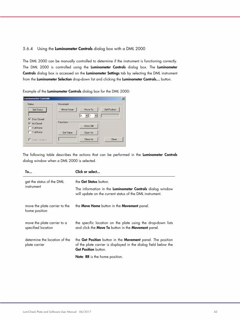
5.6.4 Using the Luminometer Controls dialog box with a DML 2000
The DML 2000 can be manually controlled to determine if the instrument is functioning correctly.
The DML 2000 is controlled using the Luminometer Controls dialog box. The Luminometer
Controls dialog box is accessed on the Luminometer Settings tab by selecting the DML instrument
from the Luminometer Selection drop-down list and clicking the Luminometer Controls… button.
Example of the Luminometer Controls dialog box for the DML 2000:
The following table describes the actions that can be performed in the Luminometer Controls
dialog window when a DML 2000 is selected.
To... Click or select...
get the status of the DML instrument
the Get Status button.
The information in the Luminometer Controls dialog window will update on the current status of the DML instrument.
move the plate carrier to the home position
the Move Home button in the Movement panel.
move the plate carrier to a specified location
the specific location on the plate using the drop-down lists and click the Move To button in the Movement panel.
determine the location of the plate carrier
the Get Position button in the Movement panel. The position of the plate carrier is displayed in the dialog field below the Get Position button.
Note: RR is the home position.

LumiCheck Plate and Software User Manual 06/2017 43
To... Click or select...
measure the well at the current location of the plate carrier
the Get Value button in the Functions panel. The RLU result displays in the dialog field below the drop-down lists.
turn off the stepper motor for the plate carrier
the Motor Off button in the Functions panel.
open the iris the Open Iris button in the Functions panel.
close the iris the Close Iris button in the Functions panel.
close the Luminometer Controls dialog box
the Close button.
The following table describes the features that are available in the Luminometer Controls dialog
box when a DML 2000 is selected.
Feature Function
Door Closed box If this box is checked, the door was closed during the last status check of the DML instrument.
If the box is not checked, the door was open during the last status check of the DML instrument.
Iris Closed box If this box is checked, the iris was closed during the last status check of the DML instrument.
If the box is not checked, the iris was open during the last status check of the DML instrument.
X at Home box If this box is checked, the plate carrier was in the home position for the X axis during the last status check of the DML instrument.
If the box is not checked, the plate carrier was not in the home position for the X axis during the last status check of the DML instrument.

LumiCheck Plate and Software User Manual 06/2017 44
Feature Function
Y at Home box If this box is checked, the plate carrier was in the home position for the Y axis during the last status check of the DML instrument.
If the box is not checked, the plate carrier was not in the home position for the Y axis during the last status check of the DML instrument.
Communicating box If this box is checked, the DML instrument is currently communicating with the HC2 System computer.
If the box is not checked, the DML instrument is currently not communicating with the HC2 System computer.
5.7 Using the QIAGEN Report Viewer window
The QIAGEN Report Viewer window displays reports.
Modifying the default settings of the report may truncate information. Do not change the size of
the report as information will not be truncated if the default settings are used.
An example of the menu bar that opens at the top of the QIAGEN Report Viewer window:
The following table describes the actions that can be performed using the QIAGEN Report Viewer
window.
To... Click or select...
print the displayed report to the default printer
the Print… button.
preview the displayed report in print format
the Print Preview… button.
The Print Preview window opens displaying the report. Use the icons in the menu bar to modify the parameters for printing the report.

LumiCheck Plate and Software User Manual 06/2017 45
To... Click or select...
save the displayed report as a *.csv file
the Save As… button. The Save File As dialog box opens. Select the directory to which the file will be saved and enter the file name in the File name: dialog field. Click the Save button.
A dialog box opens confirming the file was saved.
exit the QIAGEN Report Viewer window
click the Close button.

LumiCheck Plate and Software User Manual 06/2017 46
6 General Operation
On days of testing with digene HC2 DNA tests, perform a periodic check using the LumiCheck
Plate prior to measuring the first microplate.
To use the LumiCheck Plate with the DML instrument, the following is required:
The LumiCheck Plate Software is set up.
A user is added to the LumiCheck Plate Software.
The DML instrument is initialized and has established communication with the HC2 System
computer.
A mechanical test has been performed.
If using a DML 2000, the following additional tasks are required:
The iris factor for the DML 2000 is specified.
The background baseline (100) is determined.
The LumiCheck Plate Software only accepts the English language character set. Only use English
language characters when using the software.
6.1 Logging in
1. Power ON all the HC2 System hardware components.
Refer to the applicable user manual for additional information.
2. Log in to the Windows operating system.
Note: Refer to digene HC2 System Software User Manual for additional instructions.
3. Start the LumiCheck Plate Software by double-clicking the LumiCheck icon on the Windows
desktop.
Note: The LumiCheck Plate Software can also be started by clicking the Windows Start menu,
selecting All Programs, selecting HC2 System Software, and selecting the applicable software
version of LumiCheck v2.0.1, LumiCheck v2.0.2 or LumiCheck v2.0.3.
4. In the User Login dialog box, enter the user ID and password in the applicable dialog fields
and select the applicable serial number of the DML instrument from the Luminometer Serial
Number: drop-down list. Click OK.
Note: If a DML instrument has not been added, a dialog box opens informing the user to add
a DML instrument. See “Adding a DML instrument,” page 49, for additional instructions.
The LumiCheck Plate Software opens with the Periodic Check tab at the forefront.

LumiCheck Plate and Software User Manual 06/2017 47
6.2 Modifying the laboratory header information
1. On the Utilities/Settings tab, click the Change… button.
The Edit Laboratory Information dialog box opens.
2. Enter the applicable laboratory name in the Name dialog field.
Important: Do not use “QIAGEN” in the name.
Note: Limit the name to a maximum of 20 characters to make sure the name fits in the printing
area of the report.
3. In the Header: dialog field, type the information that is desired to display on all reports, such
as the laboratory’s name, address, phone number and fax number.
Note: Limit the header information to 4 lines of 50 alphanumeric characters.
4. Click OK.
The software returns to the Utilities/Settings tab, and the information displays in the respective
dialog fields.
6.3 Managing users
A user ID and password are required to use the LumiCheck Plate Software. User IDs have an
associated access level, either operator or supervisor, which determines the software functions the
user can perform.
The LumiCheck Plate Software only requires one user that has supervisor access level. Using
individual user IDs with the LumiCheck Plate Software provides control over software functions
and data access based on the user ID.
Users with operator access level can perform the following functions:
Manage DML instruments
Modify DML instrument settings
Select the DML instrument to use
Initiate DML instrument mechanical tests
Perform routine periodic checks of the DML instrument
Print, view, delete and export master and periodic check reports
View trend information

LumiCheck Plate and Software User Manual 06/2017 48
Users with supervisor access level can perform all operator access level functions along with the
following functions:
Manage user IDs, passwords and access levels
Manage laboratory name and report header information
Perform periodic master measurements
View periodic check reports to determine the degree of performance above the minimum
acceptability
Archive data, view archived data and restore the current data
If using the DML 2000, perform an iris factor analysis to establish the iris factor for a specific
luminometer
6.3.1 Adding users
The LumiCheck Plate Software installs with one user that has supervisor access level. Use the
following case-sensitive credentials to log into the software the first time:
User ID: Super
Password: super
Recommendation: Reserve the user ID and password combination of “Super” and “super” for
QIAGEN Technical Services. Do no use this user ID to perform testing.
Only users with supervisor access level can perform the following procedure.
1. On the Users tab, click the New… button.
The ID Entry dialog box opens.
2. Enter the new user ID in the Enter new ID: dialog box.
Note: The user ID must consist of alphanumeric characters with a minimum of 5 characters
and a maximum of 25 characters.
3. Click OK.
The Edit User dialog box opens.
4. Enter the password for the user ID in the Password: and Confirm password: dialog boxes.
Note: The password must consist of alphanumeric characters with a minimum of 5 characters
and a maximum of 8 characters and is case-sensitive.
5. Select either the Operator or Supervisor access level from the User Type: drop-down list.
6. Click OK.
The software returns to the Users tab, and the user ID displays in the list.

LumiCheck Plate and Software User Manual 06/2017 49
6.3.2 Editing users
Only users with supervisor access level can perform the following procedure.
1. On the Users tab, select the user ID to modify and click the Edit… button.
The Edit User dialog box opens.
2. Edit the desired parameters.
Edit the user ID password using the Password: and Confirm password: dialog boxes.
Edit the user ID access level by selecting the applicable access level from the User Type:
drop-down list.
3. Click OK.
The software returns to the Users tab.
6.3.3 Deleting a user
Only users with supervisor access level can perform the following procedure.
1. On the Users tab, highlight the user ID to delete and click the Delete button.
A dialog box opens to confirm the deletion of the user.
2. Select the applicable response to confirm the deletion of the user.
The dialog box closes, and the user is deleted from the list.
6.4 Managing the DML instrument
The DML instrument measures the RLU of samples contained in a microplate that is placed in the
instrument. The photomultiplier tube (PMT) is the component of the DML instrument used to detect
light emitted by chemiluminescence.
The user cannot adjust the PMT or DML instrument as the PMT does not have a traceable standard
for calibration. The assay acceptance criteria of the HC2 System are used to determine if the DML
instrument is performing within specification; therefore, if the results of a digene HC2 DNA test
meet the assay acceptance criteria, the DML instrument is functioning properly.
6.4.1 Adding a DML instrument
The LumiCheck Plate Software can maintain the data for multiple DML instruments; however,
connect only one DML instrument to the HC2 System computer at a time.

LumiCheck Plate and Software User Manual 06/2017 50
If adding a DML 2000, the following settings are specified during the manufacturing of the DML
instrument, and the user cannot modify these settings:
Settle Time: — indicates the time to pause between the movement of the plate carrier and
plate measurement
RLU Factor: — the scale of the RLU reported by the DML instrument
1. On the Luminometer Settings tab, click the Add Luminometer button.
The Luminometer Settings dialog box opens.
2. In the COM Port: drop-down list, select the communications port that connects the DML
instrument to the HC2 System computer. Refer to the applicable DML instrument user manual
to determine the COM port to select.
3. In the Serial Number: dialog field, enter the serial number of the DML instrument.
Note: The serial number of the DML instrument is located on the back of the DML instrument.
4. In the Instrument Type: drop-down list, select the type of the DML instrument.
Important: Selecting the incorrect type will result in LumiCheck Plate Software or instrument
errors.
5. If a DML 2000 is being added, type the iris factor into the Iris Factor: dialog box.
The iris factor is a value specific to the DML instrument and is supplied on the Iris Factor
Correction Sheet supplied with the DML instrument.
6. Click OK.
The Luminometer Settings dialog box closes.
7. A dialog box will open to prompt for the performance of a mechanical test.
See “Performing a mechanical test,” page 51, for additional instructions.
If a DML 2000 was added, a dialog box will open to prompt for the performance of a
background baseline (100) reading. See “Understanding the background baseline (100)
reading,” page 52, for additional instructions.
The DML instrument will be available for use with the LumiCheck Plate Software.
8. On the Luminometer Settings tab, click the Luminometer Controls… button in the Luminometer
Actions panel.
The Luminometer Controls dialog box opens.
The communication of the LumiCheck Plate Software with the DML instrument is checked to
make sure the DML instrument settings are correct.
9. For a DML 3000, select H and 12 from the drop-down lists in the Functions panel.
For a DML 2000, select H and 12 from the drop-down lists in the Movement panel.
10. For a DML 3000, click the Read Well button in the Functions panel.

LumiCheck Plate and Software User Manual 06/2017 51
For a DML 2000, click the Move To button in the Movement panel.
If the DML instrument does not initialize, make sure the DML instrument settings are correct and
check the connections between the HC2 System computer and the DML instrument.
If the LumiCheck Plate Software communicates with the DML instrument, the DML instrument
executes the command. The DML instrument is ready for use.
6.4.2 Modifying the settings of a DML instrument
The settings of a DML instrument are modified using the Luminometer Settings dialog box.
1. On the Luminometer Settings tab, click the Settings… button in the Luminometer Actions panel.
The Luminometer Settings dialog box opens.
2. Modify the parameters of the DML instrument and click OK.
Note: Only the COM Port: dialog field may be modified for the DML 3000.
The COM Port: and Iris Factor: dialog fields may be modified for the DML 2000.
3. Click the OK button.
The Luminometer Settings dialog box closes.
6.4.3 Performing a mechanical test
A mechanical test for the DML instrument selected must have been completed and valid before the
LumiCheck Plate can be used. During a mechanical test, the LumiCheck Plate Software:
Checks the connection between the HC2 System computer and the DML instrument
Moves the DML instrument plate carrier to the home position
Opens and closes the iris of the DML instrument (DML 2000 only)
During the mechanical test, error messages will display if a problem is detected. For information
about errors experienced during the mechanical test, refer to the applicable DML instrument user
manual for additional information.
A mechanical test may be prompted when a user logs into the LumiCheck Plate Software based
on the setting in the Luminometer Settings tab. See “Using the Luminometer Settings tab,”
page 34, for additional information.
A mechanical test can be performed at any time using the Perform Mechanical Test button on the
Luminometer Settings tab. See “Using the Luminometer Settings tab,” page 34, for additional
information.

LumiCheck Plate and Software User Manual 06/2017 52
If the Display mechanical test report after completion box is checked on the Luminometer Settings
tab, the QIAGEN Report Viewer window displays the mechanical test report after the mechanical
test is completed. The QIAGEN Report Viewer window opens. See “Using the QIAGEN Report
Viewer window,” page 44, for additional instructions.
6.4.4 Understanding the background baseline (100) reading
The background baseline (100) reading only applies to the DML 2000. A background baseline
(100) reading is a series of one hundred measurements that are averaged. The minimum,
maximum and average measurements are reported and stored. Each time a new background
baseline (100) is measured, the plate background (10) data are cleared.
Background baseline (100) readings are performed to establish the background offset
parameters. The background maximum is determined by adding the background offset parameter
to the average of the background baseline (100) readings; the background minimum is
determined by subtracting the background offset parameter from the average of the background
baseline (100) readings. The background offset parameter can be modified by the user; the
background maximum and background minimum parameters are automatically calculated based
on the background offset parameter.
Recommendation: Do not exceed 20 for the background offset parameter.
The background maximum and minimum parameters are displayed in the Background Offset
panel on the Luminometer Settings tab. The result and date of the most recent background
baseline (100) reading is displayed in the Background Baseline panel on the Luminometer
Settings tab. See “Using the Luminometer Settings tab with a DML 2000,” page 38, for
additional instructions.
The background offset parameters determine if the plate background (10) reading is within
specification. See “Understanding the plate background (10) reading,” page 53, for additional
information.
6.4.5 Performing a background baseline (100) reading
Perform a background baseline (100) reading of the DML 2000 before using the instrument for
the first time.
Note: A mechanical test must have been performed before a background baseline (100) reading
can occur. See “Performing a mechanical test,” page 51, for additional instructions.

LumiCheck Plate and Software User Manual 06/2017 53
1. On the Luminometer Settings tab, click the Set Background Baseline (100) button.
After all background measurements are complete, the QIAGEN Report Viewer window opens
with the background baseline (100) report. See “Using the QIAGEN Report Viewer window,”
page 44, for additional instructions.
2. Make sure that the average background measurement is 80–500 RLU and the difference
between the minimum and maximum measurements does not exceed 20 RLU.
If the specified parameters are not met, contact QIAGEN Technical Services.
6.4.6 Understanding the plate background (10) reading
The plate background (10) reading only applies to the DML 2000. The plate background (10)
reading is a series of ten measurements that is performed immediately prior to plate measurement.
The results of the reading are averaged and compared to the parameters displayed on the
Luminometer Settings tab. For information about how the parameters are determined, see
“Understanding the background baseline (100) reading“, page 52, for additional instructions.
There are two possible outcomes of the plate background (10) reading:
If the plate background (10) reading is within specification, the average RLU of the plate
background (10) reading is subtracted from all subsequent RLU results of the plate
measurement. The mean, maximum and minimum RLU values of the ten measurements are
recorded in the trend database.
If the plate background (10) RLU is not within specification, the LumiCheck Plate Software
displays a message stating the plate background (10) is out of specification. The plate
measurement may either be continued or canceled.
If the plate measurement is continued, the average RLU of the plate background (10) reading
is subtracted from all subsequent RLU results of the plate measurement. A statement that the
plate background (10) is out of specification displays on the assay report. Refer to digene
HC2 System Software Manual for additional instructions to troubleshoot plate background
problems.
6.4.7 Establishing the iris factor
The establishment of the iris factor is only required for the DML 2000. The iris factor is supplied in
the technical documentation supplied with the DML 2000. If the iris factor cannot be found in the
technical documentation, the LumiCheck Plate can be used to determine the iris factor.
When the iris factor is established using the LumiCheck Plate Software, the iris factor is
automatically assigned to the associated DML 2000 and replaces the iris factor specification
currently specified in the LumiCheck Plate Software.

LumiCheck Plate and Software User Manual 06/2017 54
Note: Only users with supervisor access level can establish the iris factor.
1. Power ON the LumiCheck Plate.
See “Powering ON and OFF the LumiCheck Plate,” page 55, for additional instructions.
2. Check the LumiCheck Plate battery.
See “Checking the LumiCheck Plate battery,” page 55, for additional instructions.
3. Load the LumiCheck Plate into the DML instrument with the notched corner in the upper-right
position.
Refer to the applicable DML instrument user manual for additional information about loading a
plate.
4. On the Utilities/Settings tab, click the Iris Factor… button.
The New Iris Factor dialog box opens.
5. Click the Measure… button.
The Calculating Iris Factor dialog box opens and displays a progress bar during the iris factor
measurements.
When the iris factor is established, the QIAGEN Report Viewer window opens. See “Using the
QIAGEN Report Viewer window,” page 44, for additional instructions.
6.4.8 Manually controlling the DML instrument
The DML instrument can be manually controlled to determine if the instrument is functioning
correctly. The DML instrument is controlled using the Luminometer Controls dialog box. Depending
on the type of DML instrument, see “Using the Luminometer Controls dialog box with a DML
3000,” page 37, or “Using the Luminometer Controls dialog box with a DML 2000,” page 42,
for additional instructions.
If the DML instrument is not powered ON or is not connected to the HC2 System computer, a
dialog box opens stating an error occurred during the initialization of the DML instrument.
6.4.9 Deleting a DML instrument
1. On the Luminometer Settings tab, select the applicable DML instrument serial number from the
drop-down list in the Luminometer Selection panel.
2. Click the Remove Luminometer button.
A dialog box opens to confirm the deletion of the DML instrument.
3. Select the applicable response to confirm the deletion of the DML instrument.
The dialog box closes, and the DML instrument serial number is deleted from the Luminometer
Selection drop-down list.

LumiCheck Plate and Software User Manual 06/2017 55
6.5 Using the LumiCheck Plate
6.5.1 Powering ON and OFF the LumiCheck Plate
The LumiCheck Plate power switch is located on the bottom of the LumiCheck Plate. To power ON
the LumiCheck Plate, use the blunt end of the battery test tool to move the switch to the “1”
position. To power OFF the LumiCheck Plate, use the blunt end of the battery test tool to move the
switch to the “0” position.
6.5.2 Checking the LumiCheck Plate battery
The battery life will decrease if the LumiCheck Plate is powered ON for more than the few minutes
required to perform the periodic check. Make sure to power OFF the LumiCheck Plate when not in
use.
CAUTION
Damage to the instrument
The activation switch and battery test button are fragile parts. Handle with care
and pay attention to prevent damage to these parts.
1. Power ON the LumiCheck Plate.
To power ON the LumiCheck Plate, see “Powering ON and OFF the LumiCheck Plate,”
page 55, for additional instructions.
2. Using the blunt end of the battery test tool, lightly press the recessed battery test button and
press the activation switch.
Important: Do not press the recessed battery test button with excessive force as the switch can
dislodge inside the LumiCheck Plate. If dislodged, the battery test button will remain pressed
and cause the LumiCheck Plate battery to drain.
The red LED should illuminate indicating that the LumiCheck Plate battery is functioning. If the
red LED dims or does not illuminate, replace the LumiCheck Plate battery. See ”Replacing the
LumiCheck Plate battery,” page 82, for additional instructions.
3. To make sure that the recessed battery test button is not dislodged, press the activation switch.
The red LED should not illuminate.
If the red LED illuminates while pressing the activation switch, the battery test button is likely
dislodged. Contact QIAGEN Technical Services for assistance.

LumiCheck Plate and Software User Manual 06/2017 56
6.6 Managing master files
A master file is created to establish the specifications for a combination of a LumiCheck Plate and
a DML instrument. The master file is created from measurements of the light‐containing wells of the
LumiCheck Plate. If the measurements are within specification, the master file is created that
includes the expected RLU values and normalized ratios for the LumiCheck Plate and DML
instrument combination.
The master file is stored and utilized as a reference to evaluate the stability of the DML instrument.
After the master file is created, periodic checks of the DML instrument are performed by
comparing the periodic check to the master file. Periodic check measurements not within the
observed RLU to expected RLU ratio specification will fail.
Only users with supervisor access level can manage master files, with the exception of deleting a
master file.
6.6.1 Taking measurements for a master file
A mechanical test is not required to take measurements with the DML 3000; however, it is
recommended to complete the mechanical test before taking measurements.
Before taking measurement for a master file:
The DML instrument must be added to the LumiCheck Plate Software and selected as the
current DML instrument in the Luminometer Settings tab. See “Adding a DML instrument,”
page 49, for additional instructions.
For the DML 2000, a background baseline (100) must be complete. See “Performing a
background baseline (100) reading,” page 52, for additional information.
1. On the Periodic Check tab, click the Measurements… button in the Master Files panel.
The Measurements dialog box opens.
2. Click the New… button.
The New Measurement dialog box opens.
3. Select the LumiCheck Plate serial number from the Plate SN: drop‐down list.
If using the LumiCheck Plate for the first time, enter the LumiCheck Plate serial number in the
Plate SN: dialog field.
Note: The LumiCheck Plate serial number can be found on the bottom of the LumiCheck Plate.

LumiCheck Plate and Software User Manual 06/2017 57
4. Make sure the correct DML instrument serial number is displayed in the Lum SN: drop-down
list.
5. If the incorrect DML instrument serial number is displayed, exit the dialog boxes and select the
correct DML instrument in the Luminometer Settings tab.
6. Modify the name of the data file in the Data File: dialog field, as applicable.
Note: The data file has a maximum of 40 characters, and the default name is provided in the
following format: [DML instrument serial number]-[LumiCheck Plate serial number]-[date]‐[time].
7. Click the Measure… button.
The LumiCheck Measurement dialog box opens.
8. Remove the LumiCheck Plate from the protective case.
9. Power ON the LumiCheck Plate and check the LumiCheck Plate battery.
See “Using the LumiCheck Plate,” page 55, for additional instructions.
10. Load the LumiCheck Plate into the DML instrument with the notched corner in the upper-right
position.
Refer to the applicable DML instrument user manual for additional information about loading a
plate.
11. Click the Start button to start the measurement of the plate.
The DML instrument measures wells A1 through A8 five times. Two status bars display during
measurement. The upper status bar displays the status of the current measurement cycle; the
lower status bar displays the status of all the measurements. The plate measurement process
takes less than 3 minutes.
12. When the plate measurement is complete, click OK.
A dialog box opens with instructions to remove and power OFF the LumiCheck Plate.
13. Remove and power OFF the LumiCheck Plate. Click OK.
14. Click the Close button.
6.6.2 Printing the measurements for a master file
The measurements for a master file may be printed from the Measurements dialog box or the
Master File Data Analysis dialog box.
To print the measurements for a master file from the Measurements dialog box, follow this
procedure:
1. On the Periodic Check tab, click the Measurements… button in the Master Files panel.
The Measurements dialog box opens.

LumiCheck Plate and Software User Manual 06/2017 58
2. Select the applicable data file in the list.
3. Click the Print button.
The QIAGEN Report Viewer window opens. See “Using the QIAGEN Report Viewer window,”
page 44, for additional instructions.
4. Click the Close button to exit the QIAGEN Report Viewer window.
5. Click the Close button to exit the Measurements dialog box.
To print the measurements for a master file from the Master File Data Analysis dialog box, follow
this procedure:
1. On the Periodic Check tab, click the Create Master… button in the Master Files panel.
The Master File Data Analysis dialog box opens.
2. Select the applicable data file in the list.
3. Click the Print button.
The QIAGEN Report Viewer window opens. See “Using the QIAGEN Report Viewer window,”
page 44, for additional instructions.
4. Click the Close button to exit the QIAGEN Report Viewer window.
5. Click the Cancel button to exit the Master File Data Analysis dialog box.
6.6.3 Deleting the measurements for a master file
1. On the Periodic Check tab, click the Measurements… button in the Master Files panel.
The Measurements dialog box opens.
2. Select the applicable data file form the list.
3. Click the Delete button.
A dialog opens to confirm the deletion of the data file.
4. Click the Yes button.
The data file is deleted and removed from the list in the Measurements dialog box.
5. Click the Close button to close the Measurements dialog box.
6.6.4 Creating a master file from measurements
1. On the Periodic Check tab, click the Create Master… button in the Master Files panel.
The Master File Data Analysis dialog box opens.
2. For the applicable LumiCheck Plate and DML instrument combination, select the data file to
use in creating the master file.

LumiCheck Plate and Software User Manual 06/2017 59
3. Click the Analyze button.
The ID Entry dialog box opens.
4. The master file ID displays in the dialog field at the bottom of the dialog box. As applicable,
rename the master file.
Note: The master file ID can have has a maximum of 40 characters.
5. Click OK.
The data are analyzed to make sure that the values are within the manufacturer’s
specifications. A dialog box opens that displays the status of the master file.
6. Click the Yes button to view the report for the master file or click the No button to close the
Master File Data Analysis dialog box and return to the Periodic Check tab.
If the Yes button was clicked, the QIAGEN Report Viewer window opens and displays the
master file report. See “Using the QIAGEN Report Viewer window,” page 44, for additional
instructions.
Master files with a status of pass display in the Master Files panel of the Periodic Check tab.
Master files with a status of fail will not display in the Master Files panel but can be accessed on
the Reports tab.
6.6.5 Deleting a master file
Deleting a master file removes the master file from the list in the Master Files panel of the Periodic
Check tab. The periodic checks performed using the master file remain on the Reports tab, but the
reports do not contain any analysis and report as Fail even if the periodic check had passed
when originally performed using the deleted master file.
Deleting a master file does not delete the measurements that were used to create the master file.
See “Deleting the measurements for a master file,” page 58, for instructions to delete the
measurements.
A master file may be deleted from the Periodic Check tab or the Reports tab.
To delete a master file from the Periodic Check tab, follow this procedure:
1. In the Periodic Check tab, select a master file in the Master Files panel.
2. Click the Delete button in the Master Files panel.
A dialog opens to confirm the deletion of the master file.
3. Click the Yes button.
The master file is deleted and removed from the list in the Master Files panel.
LumiCheck Plate and Software User Manual 06/2017 60
To delete a master file from the Reports tab, follow this procedure:
1. In the Reports tab, select the Periodic Master radio button.
2. Select a master file in the displayed list.
3. Click the Delete button.
A dialog opens to confirm the deletion of the master file.
4. Click the Yes button.
The master file is deleted and removed from the list.
6.7 Managing periodic checks
On days of testing, perform a periodic check once prior to reading the first plate. During a
periodic check, each of the 96 microplate wells is measured. The measurements are analyzed to
determine if the DML instrument is within the specifications based on the associated master file.
Before performing a periodic check:
The DML instrument must be added to the LumiCheck Plate Software and selected as the
current DML instrument in the Luminometer Settings tab. See “Adding a DML instrument,”
page 49, for additional instructions.
A master file should be created. A periodic test can be completed without a master file, but a
report will not be generated, and there will not be any results of the periodic check. See
“Managing master files,” page 56, for additional instructions.
For the DML 2000, the background baseline (100) must be complete. See “Performing a
background baseline (100) reading,” page 52, for additional instructions.
6.7.1 Taking measurements for a periodic check
1. On the Periodic Check tab, click the Measurements… button in the Periodic Measurements
panel.
The Measurements dialog box opens.
2. Click the New… button.
The New Measurement dialog box opens.
3. Select the LumiCheck Plate serial number from the Plate SN: drop‐down list.
If using the LumiCheck Plate for the first time, enter the LumiCheck Plate serial number in the
Plate SN: dialog field.
Note: The LumiCheck Plate serial number can be found on the bottom of the LumiCheck Plate.

LumiCheck Plate and Software User Manual 06/2017 61
4. Make sure the correct DML instrument serial number is displayed in the Lum SN: drop-down
list.
5. If the incorrect DML instrument serial number is displayed, exit the dialog boxes and select the
correct DML instrument in the Luminometer Settings tab.
6. Modify the name of the data file in the Data File: dialog field, as applicable.
Note: The data file has a maximum of 40 characters, and the default name is provided in the
following format: [DML instrument serial number]-[LumiCheck Plate serial number]-[date]‐[time].
7. Click the Measure… button.
The LumiCheck Measurement dialog box opens.
8. Remove the LumiCheck Plate from the protective case.
9. Power ON the LumiCheck Plate and check the LumiCheck Plate battery.
See “Using the LumiCheck Plate,” page 55, for additional instructions.
10. Load the LumiCheck Plate into the DML instrument with the notched corner in the upper-right
position.
Refer to the applicable DML instrument user manual for additional information about loading a
plate.
11. Click the Start button to start the measurement of the plate.
The DML instrument measures all 96 wells of the plate. A status bar displays the progress of
the measurement.
12. When the plate measurement is complete, click OK.
A dialog box opens with instructions to remove and power OFF the LumiCheck Plate.
13. Remove and power OFF the LumiCheck Plate. Click OK.
14. Click the Close button.
6.7.2 Printing the measurements for a periodic check
The measurements for a periodic check may be printed from the Measurements dialog box.
1. On the Periodic Check tab, click the Measurements… button in the Periodic Measurements
panel.
The Measurements dialog box opens.
2. Select the applicable data file in the list.
3. Click the Print button.
The QIAGEN Report Viewer window opens. See “Using the QIAGEN Report Viewer window,”
page 44, for additional instructions.

LumiCheck Plate and Software User Manual 06/2017 62
4. Click the Close button to exit the QIAGEN Report Viewer window.
5. Click the Close button to exit the Measurements dialog box.
6.7.3 Deleting the measurements for a periodic check
The measurements for a periodic check may be deleted from the Periodic Measurements panel or
the Measurements dialog box.
To delete the measurements for a periodic check from the Periodic Measurements panel, follow
this procedure:
1. In the Periodic Check tab, select a master file in the Periodic Measurements panel.
2. Click the Delete button in the Periodic Measurements panel.
A dialog opens to confirm the deletion of the master file.
3. Click the Yes button.
The master file is deleted and removed from the list in the Master Files panel.
To delete the measurements for a periodic check from the Measurements dialog box, follow this
procedure:
1. On the Periodic Check tab, click the Measurements… button in the Periodic Measurements
panel.
The Measurements dialog box opens.
2. Select the applicable data file form the list.
3. Click the Delete button.
A dialog opens to confirm the deletion of the data file.
4. Click the Yes button.
The data file is deleted and removed from the list in the Measurements dialog box.
5. Click the Close button to close the Measurements dialog box.
6.7.4 Analyzing a periodic check
1. On the Periodic Check tab, select the applicable LumiCheck Plate and DML instrument serial
numbers in the Plate SN: and Lum SN: drop-down lists.
The available data files will display in the Periodic Measurements panel.
2. Click the Analyze… button in the Periodic Measurements panel.
The Periodic Check dialog box opens.
LumiCheck Plate and Software User Manual 06/2017 63
3. Select the applicable master file from the Select Master File: drop‐down list to use in
performing the periodic check.
Note: The master file selected must have been created using the same LumiCheck Plate and
DML instrument.
4. In the Measurements panel, select the applicable data file to analyze.
5. Click the Analyze button.
The measurements of the periodic check are analyzed according to the specifications of the
master file, and an analysis file is created. A dialog box opens and displays the status of the
periodic check.
6. Click the Yes button.
The QIAGEN Report Viewer window opens. See “Using the QIAGEN Report Viewer window,”
page 44, for additional instructions.
6.7.5 Deleting a periodic check
Deleting a periodic check removes the periodic check from the list in the Reports tab. Deleting a
periodic check does not delete the measurements that were used to create the periodic check. See
“Deleting the measurements for a periodic check,” page 62, for instructions to delete the
measurements.
1. In the Reports tab, select the Periodic Checks radio button.
2. Select a data file in the displayed list.
3. Click the Delete button.
A dialog opens to confirm the deletion of the periodic check.
4. Click the Yes button.
The periodic check is deleted and removed from the list.
6.8 Viewing reports
After creating a master file or completing a periodic check, reports can be viewed using the
Reports tab.
The available reports are as follows:
LumiCheck periodic master set values
LumiCheck periodic test report
Iris factor analysis

LumiCheck Plate and Software User Manual 06/2017 64
All reports include the following information:
Date of the measurements
The LumiCheck Plate Software version used to measure the plate
Serial number of the DML instrument used to measure the plate
Serial number of the LumiCheck Plate used to perform the measurements
Lines for a supervisor to sign and date the report
1. On the Reports tab, select either the Periodic Master or Periodic Checks radio button.
2. In the Show panel, select the All, Passed or Failed radio button to view the applicable data
files.
Note: When viewing all data files, data files that failed are highlighted in red.
3. In the list, select the applicable data file.
4. Click the Show… button.
The QIAGEN Report Viewer window opens. See “Using the QIAGEN Report Viewer window,”
page 44, for additional instructions.
5. Click the Close button to exit the QIAGEN Report Viewer window.

LumiCheck Plate and Software User Manual 06/2017 65
6.8.1 Understanding the LumiCheck periodic master set values report
The LumiCheck periodic master set values report includes the pass or fail result for each
microplate well and the acceptable ranges for future periodic checks based on the master file.
Example of the LumiCheck periodic master set values report:

LumiCheck Plate and Software User Manual 06/2017 66
The header of the LumiCheck periodic master set values report includes the laboratory header
information. See “Modifying the laboratory header information,” page 47, for instructions to
change the laboratory header information.
The status of the master file is listed in the header. Valid results have RLUs are Valid in the header.
The following table describes the fields in the header of the LumiCheck periodic master set values
report.
Field Description
Data Record: ID of the created master file
Measurement Record: ID of the data file that contains the measurements used to create the master file
User ID: User ID logged into the LumiCheck Plate Software during the creation of the master file
The Raw Data section provides the RLU values for each of the measurements and the average
measurement for each of the 8 light-emitting wells. The Normalized Ratios section provides the
normalized ratios and the average normalized ratio for each of the 8 light-emitting wells. The
Master Set Up Verification section provides the specification for the coefficient of variation (CV),
the CV result and the pass/fail result for each of the 8 light-emitting wells. The Master Set
Expected Ranges section provides the specifications to which the periodic check must meet for a
pass result.
The following table describes the fields in the Master Set Expected Ranges panel.
Field Description
Normalized ratios [and] RLUs
The light-emitting well of the LumiCheck Plate that was measured
QIAGEN Specs Minimum Specification defined by QIAGEN

LumiCheck Plate and Software User Manual 06/2017 67
Field Description
QIAGEN Specs Maximum Specification defined by QIAGEN
Calculated Acceptable Values Average
The normalized ratio average or RLU average as calculated from the measurements of the light-emitting well
Calculated Acceptable Values Minimum
The normalized ratio average or RLU average as calculated by multiplying the Calculated Acceptable Values Average result by the QIAGEN Specs Minimum
Calculated Acceptable Values Maximum
The normalized ratio average or RLU average as calculated by multiplying the Calculated Acceptable Values Average result by the QIAGEN Specs Maximum
RLUs The light-emitting well of the LumiCheck Plate that was measured
6.8.2 Understanding the LumiCheck periodic test report
The LumiCheck periodic check report displays the results of the periodic check. The periodic check
report includes the RLU, cross-talk, blank well, normalized ratios and RLU verification results. The
normalized ratios for the individually measured wells are calculated and analyzed against the
applicable master file. The periodic check report includes the expected ranges for the pass/fail
criteria for each test.

LumiCheck Plate and Software User Manual 06/2017 68
Example of the LumiCheck periodic test report:
The header of the LumiCheck periodic test report includes the laboratory header information. See
“Modifying the laboratory header information,” page 47, for instructions to change the
laboratory header information.
The status of the periodic check is listed in the header. Valid results have Pass in the header.

LumiCheck Plate and Software User Manual 06/2017 69
The following table describes the fields in the header of the LumiCheck periodic test report.
Field Description
Data File: ID of the data file that contains the measurements for the periodic check
Master File: ID of the master file that is the reference for the periodic check
User ID: User ID logged into the LumiCheck Plate Software during the periodic check
The Raw Data section provides the RLU values for each of the wells of the LumiCheck Plate. The
Cross-talk and Blank Well Verification section provides the results for the LumiCheck Plate wells
that do not emit light. The Normalization Ratios Verification section provides the results for each of
the 8 light-emitting wells. The RLU Verification section provides the results for light-emitting wells
A3 and A8.
The following table describes the fields in the Cross-talk and Blank Well Verification panel.
Field Description
Observed The parameter applicable to the blank wells and the average results for all of the blank wells
Customer Limits Specification maximum
Specification defined by QIAGEN
Customer Limits Specification minimum
Specification defined by QIAGEN
Pass/Fail Determination of result status by comparing the observed result to the specification

LumiCheck Plate and Software User Manual 06/2017 70
The following table describes the fields in the Normalization Ratios Verification panel.
Field Description
Observed ratio The normalized ratio for the light-emitting wells
Expected ratio Specification defined by the master file
min Specification defined by the master file
max Specification defined by the master file
Pass/Fail Determination of result status by comparing the observed normalized ratio to the specifications
O/E The ratio of the observed normalized ratio result divided by the expected normalized ratio
The following table describes the fields in the RLU Verification panel.
Field Description
Observed The RLU result for the light-emitting wells
Expected Specification defined by the master file
min Specification defined by the master file
max Specification defined by the master file
Pass/Fail Determination of result status by comparing the observed RLU to the specifications
O/E The ratio of the observed RLU result divided by the expected RLU result

LumiCheck Plate and Software User Manual 06/2017 71
6.8.3 Understanding the iris factor analysis report
The iris factor analysis report displays the result of the measurements taken during the
establishment of the iris factor. See “Establishing the iris factor,” page 53, for additional
instructions.
The iris factor analysis report is only applicable to the DML 2000.
Example of the iris factor analysis report:
The following table describes the fields in the header of the iris factor analysis report.
Field Description
Data File: ID of the data file that contains the measurements for the iris factor analysis
User ID: User ID logged into the LumiCheck Plate Software during the iris factor analysis
Iris Factor: The average of the iris factor measurements that should be used as the specification for the DML 2000

LumiCheck Plate and Software User Manual 06/2017 72
Field Description
Well: The well that is measured during iris factor analysis
Background subtraction RLU: The value of the background that is subtracted from the raw RLU measurements of the iris factor analysis
The following table describes the fields of the iris factor analysis report.
Field Description
Iris Closed The RLU result for the well with the iris closed
Iris Open The RLU result for the well with the iris open
Iris Closed Adjusted The RLU result for the well with the iris closed and the background subtraction RLU subtracted
Iris Open Adjusted The RLU result for the well with the iris open and the background subtraction RLU subtracted
Iris Factor The iris factor result as determined by dividing the Iris Open Adjusted result by the Iris Closed Adjusted result
Average Iris Factor The average of the Iris Factor results
6.9 Generating trending reports
The LumiCheck Plate Software maintains a database that is used to generate trending reports. A
trending report may be generated for the periodic check results. If using a DML 2000, a trending
report may be generated for background measurement readings.
Use trending reports to observe trends in the performance of the DML instrument over time.

LumiCheck Plate and Software User Manual 06/2017 73
1. Select the applicable radio button for the type of report.
If using a DML 3000, the only option available is the Periodic Check radio button. If using a
DML 2000, the options are the Periodic Check or Background Trending radio buttons.
2. If generating a background trending report, select the applicable DML instrument from the
Serial Number for Trend: dialog field.
Note: Trending reports for plate background readings are only possible for DML 2000
instruments.
3. Using the Start Date: and End Date: dialog fields in the Trend Range panel, enter the
applicable time period for the trending report.
If trend data exist for the type of report selected, the applicable data files populate in the list.
4. Select the applicable item in the displayed list and click the Trend… button.
The QIAGEN Report Viewer window displays the report. See “Using the QIAGEN Report
Viewer window,” page 44, for additional instructions.
6.9.1 Understanding the periodic check trending report
Each periodic check that passes is added to the database; failed periodic tests are not added to
the database. For each light-emitting well, the observed normalized ratio divided by the expected
ratios is plotted versus the date of analysis. In addition, the observed RLU result divided by the
expected RLU result for wells 3 and 8 is plotted versus the date of analysis.

LumiCheck Plate and Software User Manual 06/2017 74
Example of the periodic check trending report:

LumiCheck Plate and Software User Manual 06/2017 75

LumiCheck Plate and Software User Manual 06/2017 76
6.9.2 Understanding the background baseline (100) trending report
The background baseline (100) trending report applies only to the DML 2000.
The report includes a graph of the average, minimum and maximum RLU results for each of the
background baseline (100) readings performed for the specified DML instrument.
Periodically review the background baseline (100) trending report. The trending should be
consistent with the average line, showing minimal upward or downward movement. Monitor any
consistent trend upward or downward and contact QIAGEN Technical Services for assistance.
The following table describes the columns in the Background Baseline Measurements section of
the background baseline (100) trending report.
Column Description
Date Column containing the dates of the background baseline (100) readings performed for the specified DML instrument
Average Column containing the average RLU results of the background baseline (100) readings performed for the specific DML instrument
Range Column containing the RLU ranges of the background baseline (100) readings performed for the specific DML instrument
Min Column containing the RLU minimums of the background baseline (100) readings performed for the specific DML instrument
Max Column containing the RLU maximums of the background baseline (100) readings performed for the specific DML instrument

LumiCheck Plate and Software User Manual 06/2017 77
6.9.3 Understanding the plate background (10) trending report
The plate background (10) trending report applies only to the DML 2000.
The report includes a graph of the average, minimum and maximum RLU results for each of the
plate background (10) readings performed for the specified DML instrument.
Periodically review the plate background (10) trending report. The trending should be consistent
with the average line, showing minimal upward or downward movement. Monitor any consistent
trend upward or downward and contact QIAGEN Technical Services for assistance.
The following table describes the columns in the Current Background Baseline section of the plate
background (10) trending report.
Column Description
Date Column containing the dates of the last plate background (10) readings performed for the specified DML instrument
Average Column containing the average RLU results of the last plate background (10) readings performed for the specific DML instrument
Range Column containing the RLU ranges of the last plate background (10) readings performed for the specific DML instrument
Min Column containing the RLU minimums of the last plate background (10) readings performed for the specific DML instrument
Max Column containing the RLU maximums of the last plate background (10) readings performed for the specific DML instrument

LumiCheck Plate and Software User Manual 06/2017 78
6.10 Importing and exporting data
Data can be exported and imported from a HC2 System computer onto another HC2 System
computer. The import and export functions only transfer data files. Once the data have been
imported, the master file must be created using the imported data.
6.10.1 Exporting data
1. On the Periodic Check tab, click the Measurements… button in either the Master Files or
Periodic Measurements panel, as applicable.
The Measurements dialog box opens.
2. Select the data file to export in the list and click the Export button.
A directory dialog box opens.
Note: If exporting master file raw data, select the data file from which the current master file
was created.
3. Enter the name of the file and, using the directory, navigate to the location to which the file
will be saved.
4. Click the Save button.
The exported file will be saved as an *.lcx file.
6.10.2 Importing data
1. On the Periodic Check tab, click the Measurements… button in either the Master Files or
Periodic Measurements panel, as applicable.
The Measurements dialog box opens.
Note: Only users with supervisor access level can import data from the Master Files panel.
2. Click the Import button.
A directory dialog box opens.
3. Using the directory, navigate to the location to which the file is saved.
4. Select the *.lcx file to import.
5. Click the Open button.
The data are imported into the LumiCheck Plate Software, and a dialog box opens stating the
import is complete.
6. Click OK.
The data appear in the Measurements dialog box.
7. Click the Close button.
The data appear in the Periodic Measurements panel.
LumiCheck Plate and Software User Manual 06/2017 79
6.11 Archiving data
The data generated by the LumiCheck Plate can be archived to the hard drive of the HC2 System
computer. As data accumulate in the LumiCheck Plate Software database, the response time for
starting the LumiCheck Plate Software and viewing reports increases. If the response time
becomes unacceptable, archive the data for faster performance.
Once archived, the data will not display unless the archive is viewed. The data can never be
returned to the active data set displayed in the LumiCheck Plate Software. During archive viewing,
the data are displayed as the current data. Reports and trending reports can be generated, but
data cannot be added to the archive or modified. The archive data are removed and the current
data are activated when the current data are restored. The master files are never archived.
The LumiCheck Plate Software does not support archival to or retrieval from a Universal Serial Bus
(USB) storage device.
Only users with supervisor access level can perform the following procedure.
Important: Archiving data will remove all data for all DML instruments from displaying in the
LumiCheck Plate Software, and the data cannot be returned to the active data set.
1. On the Utilities/Settings tab, click the Archive Data… button.
The Archive Data dialog box opens.
2. Select the C:\ drive that will store the archive.
Important: Do not select any other drive as the data file must store in the correct location for
the archive to be viewed.
3. In the Archive Description dialog box, type a short name that describes the type of data being
archived.
4. Click OK.
The current data set for all DML instruments is archived and can only be viewed using the
View Archive Data… button. See “Viewing archived data,” page 80, for additional
instructions.

LumiCheck Plate and Software User Manual 06/2017 80
6.11.1 Viewing archived data
1. On the Utilities/Settings tab, click the View Archive Data… button.
The View Archive Data dialog box opens and lists the past archives. Each archive has the
date and time the archive was performed as well as the description entered by the user.
2. In the Select the Archive Drive: dialog field, select the drive containing the archive.
3. In the Select the Archive to view: dialog field, select the archive to view.
4. Click OK.
The Archived Data Warning dialog box opens and displays the following message:
“You are currently viewing archived data. Your changes will NOT be permanently saved. To
restore the current data, click ‘Restore Current Data’ from the Utilities/Settings Tab.”
5. Click OK.
6. View the archive.
Important: Do not edit or generate data while viewing an archive as the changes will not be
saved.
7. When finished viewing the archive, click the Restore Current Data on the Utilities/Settings tab
to return the archive to the archive folder.
The Restore Current Data dialog box opens and displays the following message:
“This will stop the viewing of archived data and restore the current data. Are you sure you
wish to continue?”
8. Click OK.

LumiCheck Plate and Software User Manual 06/2017 81
7 Maintenance
CAUTION
Damage to the instrument
Do not immerse the LumiCheck Plate in water or allow water to enter the
chamber of the LumiCheck Plate.
7.1 Routine cleaning
Periodically clean the LumiCheck Plate with a soft low‐lint paper towel moistened with deionized
or distilled water. Avoid contact with the light-emitting wells unless dirt or debris is present.
Cleaning the light-emitting wells excessively can alter the light output and cause the periodic
check to fail. Do not use chemicals during the cleaning as the LumiCheck Plate can be damaged.
When not in use, move the battery switch to the OFF position. Store the LumiCheck Plate in its
case.
7.2 Calibration
The LumiCheck Plate cannot be calibrated. The LumiCheck Plate is used to evaluate the stability of
the DML instrument and monitor the instrument performance by periodically testing the functions of
the DML instrument.
The LumiCheck Plate Software establishes a set of specifications for a specific DML instrument. The
specifications of the periodic check for the specific DML instrument are based on the
specifications established with the master file. The trending file based on the periodic checks of a
specific LumiCheck Plate and DML instrument provides trending information on the performance of
the LumiCheck Plate.
The LumiCheck Plate is used as an early warning of potential DML instrument failure and as a
diagnostic tool in the event of a failed digene HC2 DNA test. A failed periodic check using the
LumiCheck Plate does not invalidate prior assay results as each digene HC2 DNA test contains
internal verification criteria that validate the assay.
The LumiCheck Plate and DML instrument combination is trended over time by conducting
periodic checks using the LumiCheck Plate Software. After each periodic check, the acceptance
criteria and results are available in the generated report.

LumiCheck Plate and Software User Manual 06/2017 82
The LumiCheck Plate is designed with an internal monitoring mechanism to make sure that the
LumiCheck Plate is functioning within the specified voltage range.
7.3 Replacing the LumiCheck Plate battery
Replace the LumiCheck Plate battery as needed. To confirm the LumiCheck Plate battery requires
replacement, see “Checking the LumiCheck Plate battery,” page 55, for additional instructions.
Replacement batteries for the LumiCheck Plate are available from QIAGEN. The LumiCheck Plate
Battery Replacement Package includes a battery assembly, 4 screws and a battery test tool.
1. Make sure the LumiCheck Plate is powered OFF.
See “Powering ON and OFF the LumiCheck Plate,” page 55, for additional instructions.
2. Remove the 4 battery access screws using the provided screwdriver and remove the access
panel.
Note: Do not remove any other screws. Removing other screws will alter the LumiCheck Plate
characteristics.
3. Disconnect the leads of the LumiCheck Plate battery.
4. Connect the leads of the new LumiCheck Plate battery.
5. Replace the access panel and tighten the 4 battery access screws. Use the extra screws
provided if the original screws are misplaced.
6. Perform a battery check to make sure the new battery is operating properly.
See “Checking the LumiCheck Plate battery,” page 55, for additional instructions.
7.4 Disposing of the LumiCheck Plate battery
Dispose of the LumiCheck Plate battery in accordance with national and local regulations.

LumiCheck Plate and Software User Manual 06/2017 83
8 Troubleshooting
Use this section for error handling and troubleshooting. Also refer to digene HC2 System
Software User Manual and the applicable DML instrument user manual for additional information.
If the recommended steps do not resolve the problem, contact QIAGEN Technical Services for
assistance.
8.1 Master file or periodic check fails
Comments and suggestions
The RLUs are not above the plate background (10)
a) The LumiCheck Plate battery
is not activated or is
depleted
Power ON the LumiCheck Plate. See “Powering ON and
OFF the LumiCheck Plate,” page 55, for additional
information.
Check the LumiCheck Plate battery. See “Checking the
LumiCheck Plate battery,” page 55, for additional
instructions.
Repeat the LumiCheck Plate measurement.
b) The LumiCheck Plate
orientation is incorrect in the
DML instrument
Load the LumiCheck Plate into the DML instrument with the
notched corner in the upper-right position. Refer to the
applicable DML instrument user manual for additional
information about loading a plate.
Repeat the LumiCheck Plate measurement.
c) The DML instrument fails Contact QIAGEN Technical Services.
The RLUs are above the plate background (10 RLU)
a) System or communication
error
Power OFF the HC2 System, including the HC2 System
computer and the DML instrument. Refer to the applicable
user manuals for additional instructions.
Wait 30 seconds and power ON the HC2 System.
Repeat the LumiCheck Plate measurement.

LumiCheck Plate and Software User Manual 06/2017 84
Comments and suggestions
b) DML instrument malfunction Contact QIAGEN technical Services.
c) The DML instrument is not
warmed up for a full hour
Note: Only applicable to the
DML 2000.
Allow the DML instrument to warm up for at least 1 hour.
Repeat the LumiCheck Plate measurement.
Recommendation: Leave the DML instrument powered on
at all times.
8.2 Periodic check measurement fails
Comments and suggestions
Periodic check fails the cross-talk specifications
a) The LumiCheck Plate
orientation is incorrect in the
DML instrument
Load the LumiCheck Plate into the DML instrument with the
notched corner in the upper-right position. Refer to the
applicable DML instrument user manual for additional
information about loading a plate.
Repeat the LumiCheck Plate measurement.
b) The LumiCheck Plate is dirty
or the plate mask or plate
carrier of the DML instrument
is dirty
Clean the LumiCheck Plate with a low‐lint paper towel
moistened with distilled or deionized water.
Clean the DML instrument; refer to the applicable user
manual for additional instructions.
Repeat the LumiCheck Plate measurement.
c) The DML instrument fails Contact QIAGEN Technical Services.
Periodic check fails the blank well specifications
a) The LumiCheck Plate is dirty
or the plate mask or plate
carrier of the DML instrument
is dirty
Clean the LumiCheck Plate with a low‐lint paper towel
moistened with distilled or deionized water.
Clean the DML instrument; refer to the applicable user
manual for additional instructions.
Repeat the LumiCheck Plate measurement.

LumiCheck Plate and Software User Manual 06/2017 85
Comments and suggestions
b) System or communication
error
Power OFF the HC2 System, including the HC2 System
computer and the DML instrument. Refer to the applicable
user manuals for additional instructions.
Wait 30 seconds and power ON the HC2 System.
Repeat the LumiCheck Plate measurement.
c) The DML instrument fails Contact QIAGEN Technical Services.
Well A8 fails the specifications for normalized ratio or RLU
The LumiCheck Plate battery
is not activated or is
depleted
Power ON the LumiCheck Plate. See “Powering ON and
OFF the LumiCheck Plate,” page 55, for additional
information.
Check the LumiCheck Plate battery. See “Checking the
LumiCheck Plate battery,” page 55, for additional
instructions.
Repeat the LumiCheck Plate measurement.
Individual well failure of wells A1 to A7
a) System or communication
error
Power OFF the HC2 System, including the HC2 System
computer and the DML instrument. Refer to the applicable
user manuals for additional instructions.
Wait 30 seconds and power ON the HC2 System.
Repeat the LumiCheck Plate measurement.
b) The LumiCheck Plate is dirty
or the plate mask or plate
carrier of the DML instrument
is dirty
Clean the LumiCheck Plate with a low‐lint paper towel
moistened with distilled or deionized water.
Clean the DML instrument; refer to the applicable user
manual for additional instructions.
Repeat the LumiCheck Plate measurement.
c) The individual well is
damaged
Contact QIAGEN Technical Services.
d) The DML instrument fails Contact QIAGEN Technical Services.

LumiCheck Plate and Software User Manual 06/2017 86
Comments and suggestions
Multiple wells fail
a) The LumiCheck Plate
orientation is incorrect in the
DML instrument
Load the LumiCheck Plate into the DML instrument with the
notched corner in the upper-right position. Refer to the
applicable DML instrument user manual for additional
information about loading a plate.
Repeat the LumiCheck Plate measurement.
b) The LumiCheck Plate battery
is not activated or is
depleted
Power ON the LumiCheck Plate. See “Powering ON and
OFF the LumiCheck Plate,” page 55, for additional
information.
Check the LumiCheck Plate battery. See “Checking the
LumiCheck Plate battery,” page 55, for additional
instructions.
Repeat the LumiCheck Plate measurement.
c) System or communication
error
Power OFF the HC2 System, including the HC2 System
computer and the DML instrument. Refer to the applicable
user manuals for additional instructions.
Wait 30 seconds and power ON the HC2 System.
Repeat the LumiCheck Plate measurement.
d) The DML instrument fails Contact QIAGEN Technical Services.
e) The LumiCheck Plate fails Contact QIAGEN Technical Services.

LumiCheck Plate and Software User Manual 06/2017 87
8.3 Software messages
Comments and suggestions
The most recent data file does not appear in the list of data files
Software overload Exit the LumiCheck Plate Software and restart the software.
The following message is displayed: “Instrument background out of the allowed range. Do you
want to continue measuring anyway?”
a) Average of 10 background
measurements prior to well
measurement is outside of
the established background
range
Power OFF the HC2 System, including the HC2 System
computer and the DML instrument. Refer to the applicable
user manuals for additional instructions.
Wait 30 seconds and power ON the HC2 System.
Repeat the LumiCheck Plate measurement.
b) The DML instrument fails Contact QIAGEN Technical Services.

LumiCheck Plate and Software User Manual 06/2017 88
Ordering Information
Product Contents Cat. no.
LumiCheck Plate LumiCheck Plate, storage case, screwdriver, battery test tool, battery replacement package
6000-5013
LumiCheck Plate Battery Replacement Package
Replacement battery, 4 screws and battery test tool
6000-5012

LumiCheck Plate and Software User Manual 06/2017 89
Appendix A — Technical Data
Characteristic Parameter
Dimensions (h x w x d) 1.43 x 8.54 x 12.79 cm
(0.56 x 3.36 x 5.04 inches)
Weight 227 g (8 ounces)
Construction Computer Numeric Control (CNC) machined aluminum body
Stainless steel back covers
Acrylic lens
Finish Black anodized aluminum
Stainless steel Black matte paint
Battery Lithium battery pack, 6.4V DC, 1 Ah
Light source 2 independently closed, loop controlled, constant light level, green LEDs
Light output 7 levels (wells A1–A7) derived from 1 LED source, ranging over 6 decades of dynamic range
1 well (A8) derived from a second LED source
Stability of the RLU values of the LED-based lights
± 10% for well A1; ± 5% for wells A2–A8
Operating Conditions
Air Temperature 15 - 32°C
Relative Humidity 15 - 75% (noncondensing)
Place of operation For indoor use only

LumiCheck Plate and Software User Manual 06/2017 90
Pollution Level II
Transportation Conditions (in manufacturer’s package)
Air Temperature -25 - 60°C
Relative Humidity 15 - 75% (noncondensing)
Storage Conditions (in manufacturer’s package)
Air Temperature 5 - 40°C
Relative Humidity 15 - 75% (noncondensing)

LumiCheck Plate and Software User Manual 06/2017 91
Appendix B — Waste Electrical and Electronic Equipment (WEEE)
This section provides information about disposal of waste electrical and electronic equipment by
users.
The crossed-out wheeled bin symbol (see below) indicates that this product must not be disposed
of with other waste; it must be taken to an approved treatment facility or to a designated
collection point for recycling, according to local laws and regulations.
The separate collection and recycling of waste electronic equipment at the time of disposal helps
to conserve natural resources and ensures that the product is recycled in a manner that protects
human health and the environment.
Recycling can be provided by QIAGEN upon request at additional cost. In the European Union,
in accordance with the specific WEEE recycling requirements and where a replacement product is
being supplied by QIAGEN, free recycling of its WEEE-marked electronic equipment is provided.
To recycle electronic equipment, contact your local QIAGEN sales office for the required return
form. Once the form is submitted, you will be contacted by QIAGEN either to request follow-up
information for scheduling collection of the electronic waste or to provide you with an individual
quote.

LumiCheck Plate and Software User Manual 06/2017 92
Index
Access level operator, 46 supervisor, 47
Activation switch, 18, 20 Archive
data, 78 view, 79
Background baseline (100) reading, 51 Battery, 19
disposal, 81 replace, 81
Battery screws, 18 Battery test, 18, 20 Cautions, 13 Cross-talk, 18 Data
archive, 78 export, 77 import, 77
DML instrument, 48 add, 48 delete, 53 manual control, 53 mechanical test, 50 modify settings, 50
Failure master file, 82 periodic check, 82 periodic check measurement, 83 software messages, 86
Installing software, 21
Iris factor, 52 Laboratory header, 46 Light-emitting wells, 18 LumiCheck Plate
battery check, 54 calibration, 80 cleaning, 80 hardware components, 17 operating system, 10 power ON and OFF, 54 requirements for use, 45 software components, 20
LumiCheck Plate Software logging in, 45
Luminometer Controls dialog box DML 2000, 41 DML 3000, 36
Luminometer Settings tab DML 2000, 37 DML 3000, 34
Master file, 55 create, 57 delete, 58 delete measurements, 57 print, 56 take measurements, 55
Measurements dialog box, 25 Mechanical test, 50 Periodic check, 55, 59
analyze, 61 delete, 62 delete measurements, 61 print measurements, 60 take measurements, 59
Periodic Check tab, 23 Plate background (10) reading, 52 Power switch, 18, 19 QIAGEN Microplate System
information, 22 QIAGEN Report Viewer window, 43 Reports
iris factor analysis, 70 LumiCheck periodic master set values, 64 LumiCheck periodic test, 66 view, 62
Reports tab, 26 Safety information
electrical safety, 14 proper use, 13 waste disposal, 14
Software installing, 21 uninstalling, 21
Software messages, 86 Technical data, 88 Trending reports
background baseline (100), 75 generate, 71 periodic check, 72 plate background (10), 76
Trends tab, 28

LumiCheck Plate and Software User Manual 06/2017 93
Uninstalling software, 21
User add, 47 delete, 48
edit, 48 management, 46
Users tab, 30 Utilities/Settings tab, 31 Warnings, 13

LumiCheck Plate and Software User Manual 06/2017 94
Ordering www.qiagen.com/contact | Technical Support support.qiagen.com | Website www.qiagen.com