lunar magnetic field measurements with a...
TRANSCRIPT
Lunar magnetic field measurements with a cubesat Ian Garrick-Bethell*
a,b, Robert P. Lin
c,b, Hugo Sanchez
d, Belgacem A. Jaroux
d, Manfred Bester
e,
Patrick Brownf, Daniel Cosgrove
e, Michele K. Dougherty
f, Jasper S. Halekas
e, Doug Hemingway
a,
Paulo C. Lozanog, Francois Martel
h, Caleb W. Whitlock
g
aDept. of Earth and Planetary Sciences, University of California, Santa Cruz, 1156 High Street,
Santa Cruz, CA, USA 95064; bSchool of Space Research, Kyung Hee University, Yongin, Gyeonggi
446-701, Republic of Korea; cDept. of Physics, University of California, 7 Gauss Way, Berkeley,
Berkeley, CA, USA 94720; dNASA Ames Research Center, Moffett Field, CA, USA 94035,
eSpace
Sciences Laboratory, University of California, Berkeley, 7 Gauss Way, Berkeley, CA, USA 94720, fSpace and Atmospheric Physics, The Blackett Laboratory, Imperial College, London, UK, SW7
2AZ, gDept. of Aeronautics and Astronautics, Massachusetts Institute of Technology, 77
Massachusetts Avenue, Cambridge, MA 02139, hEspace Inc., 30 Lynn Ave., Hull, MA, USA 02045.
*[email protected], phone: 831-459-1277
ABSTRACT
We have developed a mission concept that uses 3-unit cubesats to perform new measurements of lunar magnetic fields,
less than 100 meters above the Moon’s surface. The mission calls for sending the cubesats on impact trajectories to
strongly magnetic regions on the surface, and transmitting measurements in real-time to a nearby spacecraft, or directly
to the Earth, up until milliseconds before impact. The cubesats and their instruments are partly based on the NSF-funded
CINEMA cubesat now in Earth orbit. Two methods of reaching the Moon as a secondary payload are discussed: 1) After
launching into geostationary transfer orbit with a communication satellite, a small mother-ship travels into lunar orbit
and releases the cubesats on impact trajectories, and 2) The cubesats travel to the Moon using their own propulsion after
release into geosynchronous orbit. This latter version would also enable other near-Earth missions, such as
constellations for studying magnetospheric processes, and observations of close-approaching asteroids.
Keywords: Moon, magnetism, solar wind, cubesat, impactor, CINEMA, electrospray.
1. INTRODUCTION AND OBJECTIVES
1.1 Introduction
This paper describes a 3U (3U = 30 x 10 x 10 cm) cubesat mission to make near-surface measurements of magnetic
portions of the Moon that have remained a puzzle since the Apollo era. This mission, known as Lunar Impactor, would
carry with it a flight-tested magnetometer as the minimum payload, but solar wind and dust sensors are also plausible
and useful. In Section 1 we discuss the science and trajectory requirements that drive the Lunar Impactor mission. In
Section 2 we discuss the magnetometer and a preliminary design for a solar wind sensor. In Sections 3 and 4 we discuss
two mission-level architectures that could be used to implement Lunar Impactor: 1) A small mother-ship that releases
cubesats on impact trajectories from lunar orbit, and 2) A fully-independent 3-axis stabilized cubesat that starts in
geosynchronous orbit (GEO) and transfers to a lunar impactor trajectory using its own propulsion. In Sections 5 and 6
we address some of the technology that enables a cubesat mission of this class: communication and navigation via large
ground stations, and high-specific impulse (Isp) ion electrospray propulsion. In Section 7 we show trajectory simulations
using the electrospray propulsion system. In Section 8 we conclude that flight of either mission architecture is possible
with emerging technology within the next ~2 years. The platform behind Lunar Impactor would not only be useful for
lunar science, but also as a versatile high delta-v platform capable of other missions in near-Earth space.
1.2 Science background and mission concept
The origin of lunar magnetism is one of the oldest problems in lunar science1, 2. Its study dates to the first object to leave
the Earth: the Soviet Luna-1 in 1959. Luna-1 carried with it no cameras, but it carried a magnetometer to determine if

the Moon has a global magnetic field like the Earth’s. Luna-1 found no global magnetic field, but 12 years later
scientists were surprised to find that the Apollo 15 and 16 subsatellites had detected small (~100 km) patches of strongly
magnetized material throughout the Moon’s crust (Fig. 1). The dominant hypotheses for the formation of these magnetic
“anomalies” suggest they are from either the magnetic field of an ancient lunar dynamo3-6, or processes related to the
formation of plasmas produced during meteoroid impacts7. Solving this puzzle would help determine how the Moon fits
into the spectrum of planetary magnetism observed across our solar system and galaxy. From neutron stars to Jupiter’s
icy satellite Ganymede, many bodies can generate dynamos. Yet, we barely know if, when, or how our moon ever
generated one.
Deepening the mystery behind these magnetic patches is that some are co-located with unusual, brightly colored terrain8
(Fig. 2), known as “swirls.” One leading explanation for this bright terrain is that solar wind protons, normally a
darkening agent, are being deflected by the magnetic field, and keeping the underlying surface bright8, 9. If true, these
features are natural laboratories for space weathering, an important yet still poorly understood process that affects
spectral observations of all airless bodies, such as asteroids and Mercury10. Another explanation proposed recently is
that fine dust, which is widely believed to be lofted above the lunar surface after every terminator crossing11, 12, may be
accumulating in these regions due to solar wind interactions with the magnetic field13. Finally, these bright features are
also anti-correlated with surface-bound hydroxyl and water molecules14. Explanations for this observation are still
forthcoming, but the solution will also likely give insight into recently discovered near-surface water on the rest of the
Moon15.
Part of the difficulty in determining the origin of these features is that our measurements have poor spatial resolution,
owing to the relatively high altitudes of lunar spacecraft (~20 km). Measurements at the surface, in contrast, would give
information about the coherence of the underlying magnetization, addressing whether they formed in a uniform field, as
expected from a dynamo. Measurements of the solar wind flux would help test if the solar wind is being kept off the
surface by the magnetic field. Measurements of any lofted dust would help quantify how often lofting takes place, and
whether it is important in forming swirls.
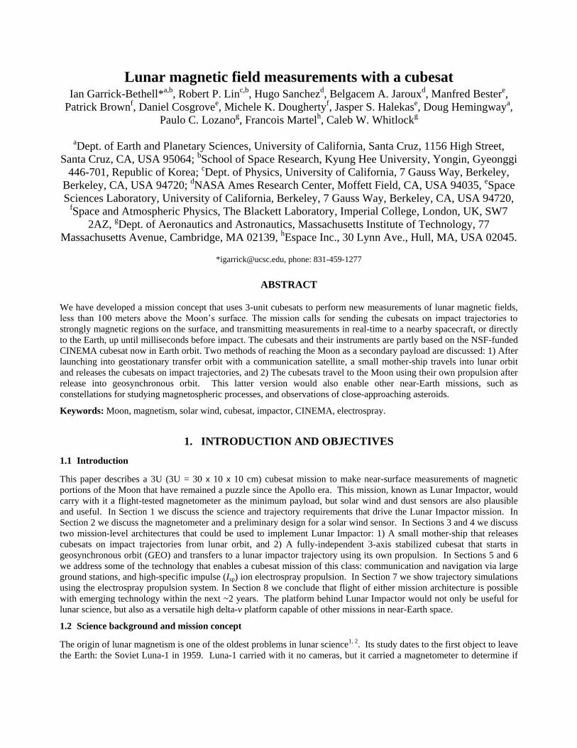
To accomplish these measurements, one would ideally land on the surface, but the costs of landing are prohibitive.
Instead, we have developed a new, leaner concept that calls for sending a cubesat on an unbraked impact trajectory into
the hearts of these features. The onboard payload (at minimum, a magnetometer) transmits data to the Earth in real-time,
up until the last milliseconds before impact with the lunar surface, enabling first-of-a-kind-measurements at < 100
meters altitude (Fig. 3).
Our initial study focuses on the Reiner Gamma swirl. Reiner Gamma’s complex surface pattern and strong magnetic
fields have made it the prototypical lunar swirl for three decades8.
Our primary science objectives at Reiner Gamma are:
1. Constrain the process(es) responsible for magnetizing the underlying material by measuring the structure of
near-surface magnetic fields. How complex are the magnetic sources? Is the field structure and direction
consistent with material magnetized in a uniform field?
2. Test the hypothesis for formation of the swirl pattern by measuring the correlation of near-surface fields,
surface markings, and solar wind flux. Does the magnetic field structure and solar wind flux correlate with the
surface pattern? Are vertical near-surface fields associated with the darkest parts of swirls, while horizontal,
near-surface fields are associated with the brightest regions, as predicted by the solar wind stand-off model9?
3. Use magnetic field and solar wind flux measurements to better understand additional phenomena such as proton
reflection16 and electric fields at swirls17, 18.
Secondary objective:
1. Test the hypothesis of lunar dust lofting and its possible role in swirl formation by measuring near-surface
lofted dust. What is the distribution of lofted dust grains near the surface (< 1 km altitude)?
Table 1 shows the measurement targets for the magnetometer, solar wind detector, and dust instrument. Because the
spacecraft is traveling at approximately 2 km/s at impact, the sampling frequency of each instrument must be high, and it
has a strong influence on the measurement resolution.

Table 1. Lunar Impactor measurement targets.
Measurement Instrument Measurement target
Magnetic field Magnetometer
(MAG)
200 samples/s (~10 m) of 3-axis magnetic field.
Solar wind Solar Wind Ion Flux
Tracer (SWIFT)
20 samples/s (~100 m) ion energy & angle distribution.
Dust LUnar Dust sensor
(LUD)
20 samples/s (~100 m) dust flux & size distribution.
Particle size < 1 μm and original charge state.
Figure 1. Lunar magnetic field contours over lunar reflectance at 750 nm (near side centered). Contours are 2-12 nT, from
the spherical harmonic model of Purucker and Nichols (2010)19, evaluated at 30 km.
Figure 2. Horizontal component of the magnetic field at Reiner Gamma, using data from individual Lunar Prospector orbits
at ~18 km altitude9.
Reiner Gamma
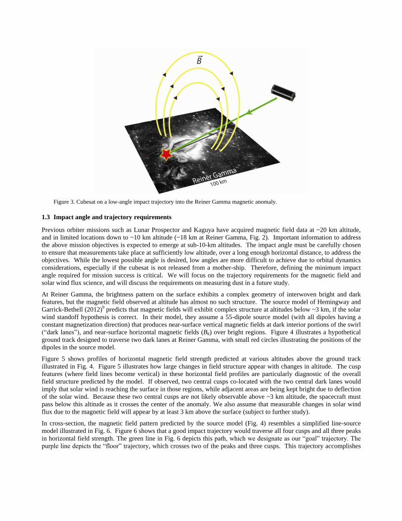
Figure 3. Cubesat on a low-angle impact trajectory into the Reiner Gamma magnetic anomaly.
1.3 Impact angle and trajectory requirements
Previous orbiter missions such as Lunar Prospector and Kaguya have acquired magnetic field data at ~20 km altitude,
and in limited locations down to ~10 km altitude (~18 km at Reiner Gamma, Fig. 2). Important information to address
the above mission objectives is expected to emerge at sub-10-km altitudes. The impact angle must be carefully chosen
to ensure that measurements take place at sufficiently low altitude, over a long enough horizontal distance, to address the
objectives. While the lowest possible angle is desired, low angles are more difficult to achieve due to orbital dynamics
considerations, especially if the cubesat is not released from a mother-ship. Therefore, defining the minimum impact
angle required for mission success is critical. We will focus on the trajectory requirements for the magnetic field and
solar wind flux science, and will discuss the requirements on measuring dust in a future study.
At Reiner Gamma, the brightness pattern on the surface exhibits a complex geometry of interwoven bright and dark
features, but the magnetic field observed at altitude has almost no such structure. The source model of Hemingway and
Garrick-Bethell (2012)9 predicts that magnetic fields will exhibit complex structure at altitudes below ~3 km, if the solar
wind standoff hypothesis is correct. In their model, they assume a 55-dipole source model (with all dipoles having a
constant magnetization direction) that produces near-surface vertical magnetic fields at dark interior portions of the swirl
(“dark lanes”), and near-surface horizontal magnetic fields (Bh) over bright regions. Figure 4 illustrates a hypothetical
ground track designed to traverse two dark lanes at Reiner Gamma, with small red circles illustrating the positions of the
dipoles in the source model.
Figure 5 shows profiles of horizontal magnetic field strength predicted at various altitudes above the ground track
illustrated in Fig. 4. Figure 5 illustrates how large changes in field structure appear with changes in altitude. The cusp
features (where field lines become vertical) in these horizontal field profiles are particularly diagnostic of the overall
field structure predicted by the model. If observed, two central cusps co-located with the two central dark lanes would
imply that solar wind is reaching the surface in those regions, while adjacent areas are being kept bright due to deflection
of the solar wind. Because these two central cusps are not likely observable above ~3 km altitude, the spacecraft must
pass below this altitude as it crosses the center of the anomaly. We also assume that measurable changes in solar wind
flux due to the magnetic field will appear by at least 3 km above the surface (subject to further study).
In cross-section, the magnetic field pattern predicted by the source model (Fig. 4) resembles a simplified line-source
model illustrated in Fig. 6. Figure 6 shows that a good impact trajectory would traverse all four cusps and all three peaks
in horizontal field strength. The green line in Fig. 6 depicts this path, which we designate as our “goal” trajectory. The
purple line depicts the “floor” trajectory, which crosses two of the peaks and three cusps. This trajectory accomplishes

the minimum amount of science for mission success. Finally, the red line represents the lowest altitude reached by the
Lunar Prospector spacecraft. Figure 7 illustrates the field directions encountered along the trajectories depicted in Fig. 6.
Longitude (degrees E)
La
titu
de
(d
eg
rees N
)
299.5 300 300.5 301 301.5 302 302.5 303
6
6.5
7
7.5
8
8.5
9
75
0n
m R
efle
cta
nce
0.1
0.105
0.11
0.115
0.12
0.125
0.13
0.135
0.14
0.145
Figure 4. Reiner Gamma overlain with a hypothetical impact trajectory (white) and the source model dipoles from
Hemingway and Garrick-Bethell (2010)9(red circles).
0 5 10 15 20 25 30 35 40 45 500
10
20
30
40
Alt = 18.0km
0 5 10 15 20 25 30 35 40 45 500
50
100
150
Alt = 5.0km
0 5 10 15 20 25 30 35 40 45 500
100
200
300
Alt = 3.0km
Hori
zo
nta
l F
ield
Str
eng
th (
nT
)
0 5 10 15 20 25 30 35 40 45 500
100
200
300
400
Alt = 1.5km
0 5 10 15 20 25 30 35 40 45 500
200
400
600
800
Alt = 0.0km
Horizontal position (km)
Figure 5. Profiles showing horizontal magnetic field strength predicted at various altitudes, based on the source model. The
top panel corresponds approximately to Lunar Prospector’s lowest altitude, where fine field structure is not observable.
Present knowledge

Figure 6. Magnetic field lines for two parallel linear sources magnetized horizontally (a simple analog to the source model
in Figs. 4 and 5). The long axis of the sources is perpendicular to their direction of magnetization. The red line represents
the lowest altitude reached by Lunar Prospector. The green line represents the “goal” impact trajectory and the purple line
represents the “floor” impact trajectory.
Figure 7. Magnetic field direction along each of the trajectories in Fig. 6. Normalized horizontal field strength is zero when
the magnetic field is vertical and unity when the field is horizontal. The red (top) profile represents the field observed by
Lunar Prospector and the green (middle) and purple (bottom) profiles represent the field along the proposed “goal” and
“floor” trajectories, respectively.
Any uncertainty in the impact position must be accounted for by lowering the required impact angle to ensure that the
important features in the field structure can be observed. We can quantify this by the diagram shown in Figure 8. We
assume the spacecraft performs useful new measurements below an altitude h, over a horizontal distance h/tanθ, where θ
is the angle the impact trajectory makes with the horizontal. Figure 8 illustrates that uncertainty in the impact position
means that the effective ground track distance is given by: d = h/tanθ - ∆d, where ∆d is the length of the landing ellipse.
Here, we assume θ can be perfectly controlled, but this assumption will be revisited in future studies.
In the case of the goal trajectory, in order to observe all four cusps, the spacecraft must traverse a horizontal distance of
~16 km after crossing the center of the albedo anomaly (at which point it must be below an altitude of 3 km in order to
traverse the two central cusps). This requires an impact angle of no more than 9.7°, when a 10% margin is added to the
desired horizontal distance. However, if the impact position uncertainty is 2 km (distinct from the 10% margin), the
maximum acceptable impact angle is 8.7°. The relationship between impact angle, ground track distance, and impact
position uncertainty is illustrated in Figure 9. Table 2 summarizes the required ground track distances and corresponding
impact angles assuming impact position uncertainties of zero and 2 km, for the goal and floor cases.
Figure 8. Impact profile showing relationship between impact angle , maximum altitude h, landing ellipse length ∆d, and
useful ground track distance d.
0 5 10 15 20 25 30 35 40 450
5
10
15
20
25
30
Impact angle (degrees from horizontal)
Gro
und
tra
ck b
elo
w h
=3
.0km
Goal
Floor
Figure 9. Low-altitude ground track vs. impact angle assuming perfect accuracy (∆d = 0, solid black line) or a 2-km landing
ellipse (∆d = 2 km, dashed black line).
In summary, to meet the science objectives an impact angle < 10° is strongly desired, but an angle as high as almost 20°
would still likely yield important new data. Even if the dipole source model we used to estimate these requirements does
not accurately represent the true magnetic field (the model’s uncertainty is, of course, the entire reason the mission is
needed), measurements below several kilometers altitude at low angles are still likely to produce important new
observations that will help address the mission objectives. In the future, we plan to further explore how solar wind flux
predictions influence the trajectory requirements, perhaps with simulations18. In addition, we must assess whether the
approach path chosen can be realized by the spacecraft trajectory (Section 7), as well choices of trajectories if multiple
Lunar Impactors are built and launched (e.g. for redundancy).
∆d
d
h
∆d
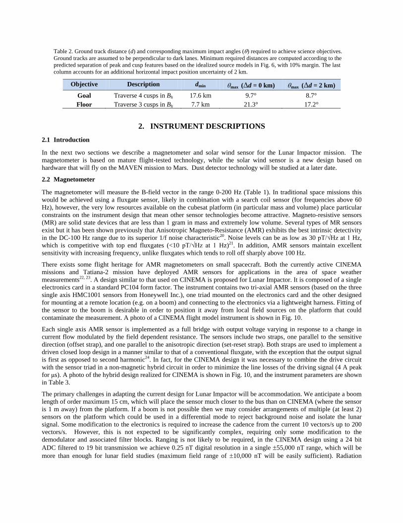
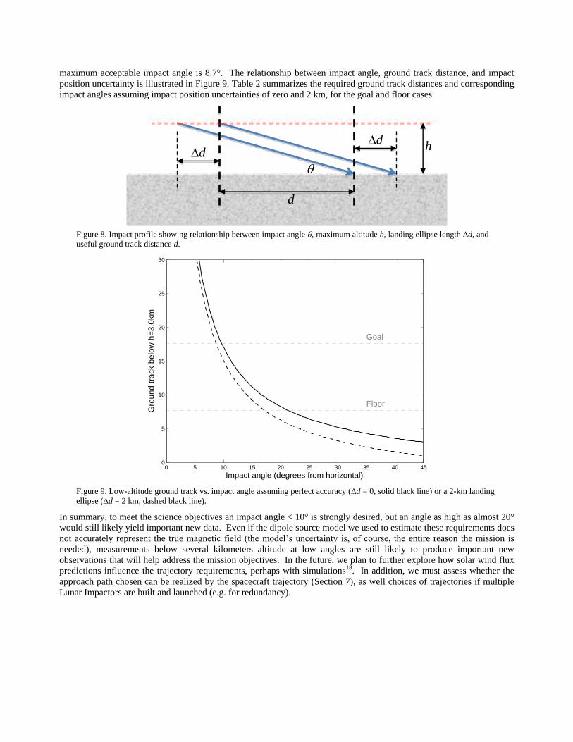
Table 2. Ground track distance (d) and corresponding maximum impact angles () required to achieve science objectives.
Ground tracks are assumed to be perpendicular to dark lanes. Minimum required distances are computed according to the
predicted separation of peak and cusp features based on the idealized source models in Fig. 6, with 10% margin. The last
column accounts for an additional horizontal impact position uncertainty of 2 km.
Objective Description dmin max (∆d = 0 km) max (∆d = 2 km)
Goal Traverse 4 cusps in Bh 17.6 km 9.7° 8.7°
Floor Traverse 3 cusps in Bh 7.7 km 21.3° 17.2°
2. INSTRUMENT DESCRIPTIONS
2.1 Introduction
In the next two sections we describe a magnetometer and solar wind sensor for the Lunar Impactor mission. The
magnetometer is based on mature flight-tested technology, while the solar wind sensor is a new design based on
hardware that will fly on the MAVEN mission to Mars. Dust detector technology will be studied at a later date.
2.2 Magnetometer
The magnetometer will measure the B-field vector in the range 0-200 Hz (Table 1). In traditional space missions this
would be achieved using a fluxgate sensor, likely in combination with a search coil sensor (for frequencies above 60
Hz), however, the very low resources available on the cubesat platform (in particular mass and volume) place particular
constraints on the instrument design that mean other sensor technologies become attractive. Magneto-resistive sensors
(MR) are solid state devices that are less than 1 gram in mass and extremely low volume. Several types of MR sensors
exist but it has been shown previously that Anisotropic Magneto-Resistance (AMR) exhibits the best intrinsic detectivity
in the DC-100 Hz range due to its superior 1/f noise characteristic20. Noise levels can be as low as 30 pT/√Hz at 1 Hz,
which is competitive with top end fluxgates (<10 pT/√Hz at 1 Hz)21. In addition, AMR sensors maintain excellent
sensitivity with increasing frequency, unlike fluxgates which tends to roll off sharply above 100 Hz.
There exists some flight heritage for AMR magnetometers on small spacecraft. Both the currently active CINEMA
missions and Tatiana-2 mission have deployed AMR sensors for applications in the area of space weather
measurements22, 23. A design similar to that used on CINEMA is proposed for Lunar Impactor. It is composed of a single
electronics card in a standard PC104 form factor. The instrument contains two tri-axial AMR sensors (based on the three
single axis HMC1001 sensors from Honeywell Inc.), one triad mounted on the electronics card and the other designed
for mounting at a remote location (e.g. on a boom) and connecting to the electronics via a lightweight harness. Fitting of
the sensor to the boom is desirable in order to position it away from local field sources on the platform that could
contaminate the measurement. A photo of a CINEMA flight model instrument is shown in Fig. 10.
Each single axis AMR sensor is implemented as a full bridge with output voltage varying in response to a change in
current flow modulated by the field dependent resistance. The sensors include two straps, one parallel to the sensitive
direction (offset strap), and one parallel to the anisotropic direction (set-reset strap). Both straps are used to implement a
driven closed loop design in a manner similar to that of a conventional fluxgate, with the exception that the output signal
is first as opposed to second harmonic24. In fact, for the CINEMA design it was necessary to combine the drive circuit
with the sensor triad in a non-magnetic hybrid circuit in order to minimize the line losses of the driving signal (4 A peak
for μs). A photo of the hybrid design realized for CINEMA is shown in Fig. 10, and the instrument parameters are shown
in Table 3.
The primary challenges in adapting the current design for Lunar Impactor will be accommodation. We anticipate a boom
length of order maximum 15 cm, which will place the sensor much closer to the bus than on CINEMA (where the sensor
is 1 m away) from the platform. If a boom is not possible then we may consider arrangements of multiple (at least 2)
sensors on the platform which could be used in a differential mode to reject background noise and isolate the lunar
signal. Some modification to the electronics is required to increase the cadence from the current 10 vectors/s up to 200
vectors/s. However, this is not expected to be significantly complex, requiring only some modification to the
demodulator and associated filter blocks. Ranging is not likely to be required, in the CINEMA design using a 24 bit
ADC filtered to 19 bit transmission we achieve 0.25 nT digital resolution in a single 55,000 nT range, which will be
more than enough for lunar field studies (maximum field range of 10,000 nT will be easily sufficient). Radiation

susceptibility of the externally mounted sensors is not anticipated to be a problem, as the HMC1001 sensors do not show
significant degradation of sensitivity in radiation dose testing25.
Figure 10. Left: Photo of the hybrid magnetoresistive sensor. Right: Photo of the CINEMA magnetometer
(MAGIC). It is composed of PC104 card and hybrid sensor connected by a 1 m harness.
The CINEMA design has been launched once to date in 2012. The same design will see two more launches in 2013 and
a modified design will launch on the NASA Sunjammer mission in 2014. It is anticipated the Sunjammer magnetometer
electronics design could be implemented in FPGA, depending on schedule, which would be timely for Lunar Impactor as
it will reduce the footprint required on the cubesat platform to an area less than half the size of the current PC104 card.
Table 3. Key parameters of the Lunar Impactor magnetometer (derived from CINEMA design).
Property Value
Mass 0.12 kg
Power 400 mW (science mode)
Volume Sensor head 10 cm3, Electronics 173 cm3 (9 cm x 9.6 cm x 2 cm)
Sensitivity <2 nT
Cadence 1 vector/s (HK mode), 200 vectors/s (science mode)
Telemetry <2.5 kbits per second
Noise Density 50 pT/√Hz at 1 Hz
Temperature -50o C to +60o C
2.3 SWIFT (Solar Wind Ion Flux Tracer)
The SWIFT instrument is designed to track the deflection and deceleration of incoming solar wind ions at low altitudes
within lunar crustal magnetic fields. The measurement requirements for a solar wind sensor for Lunar Impactor are
stringent. An optimal sensor must cover a large portion of one hemisphere, with an energy range from fast solar wind
down to highly decelerated solar wind (with good energy resolution over this range). It must also make measurements
with a very high cadence in order to trace the spatial structure of the deflected solar wind ion fluxes inside the magnetic
anomaly region at sub-km scales, while the measurement platform skims through the anomaly at ~2 km/s. Finally, it
must also do all of this with the very low resources available for a cubesat-style payload.
SWIFT provides a sensor optimized for this task. The SWIFT sensor measures reduced ion distribution functions as a
function of two orthogonal velocity components extremely rapidly; these can then be de-convolved to provide a 2-
dimensional map of ion flux for each energy step. To accomplish this, SWIFT utilizes a single hemispherical
electrostatic analyzer with two crossed apertures, each with a 120° x 10° instantaneous field of view, with electrostatic
deflection to cover all angles in a 120° x 120° field of view. By sweeping the voltage on the inner hemisphere
logarithmically, and sweeping the voltage on the two deflectors at each energy step, we can cover all angles for ions with

energies from 100 eV to 2 keV in as fast as 50 ms (20 Hz). The instrument also has a solar wind tracking mode, which
provides better time resolution, at the expense of a reduced angular field of view and energy coverage (centered on the
solar wind peak).
The electrostatic analyzer for SWIFT utilizes a full hemisphere design rather than the top-hat more typically used for a
less resource-constrained instrument, allowing a single detector to accept particles over a much larger angular range
(120° x 10°). This naturally reduces the intrinsic angular resolution (in effect, the sensor measures a distribution reduced
in one velocity dimension); however, by utilizing two detectors with perpendicular fields of view (Fig. 11), we can de-
convolve the full ion distribution.
Table 4. Key parameters of the Lunar Impactor SWIFT instrument.
Capability Lunar Impactor Requirement SWIFT performance
Energy Range 100 eV – 2 keV Intrinsic 10 eV – 5 keV
Fast Sweep 100 eV – 2 keV
Energy Resolution 33% Intrinsic 15%
Fast Sweep 33%
Measurement Cadence 20 Hz
(100 m scale)
Fast Sweep 20 Hz
SW Tracking 200 Hz
FOV 90° x 90° 2 x 120° x 120°
Crossed FOVs
Angular Resolution 20° x 20° 10° x 10°
The analyzer is in part based on a similar instrument flown on ISEE-3 in 1980, and the associated electronics have been
successfully flown by UCB on the ISEE-3, Wind, FAST, THEMIS missions (and currently in use on the MAVEN
STATIC and SWIA instruments (Fig. 12), now in spacecraft level environmental testing). By utilizing a hemispherical
analyzer instead of a more typical top-hat, we can measure a large portion of 2π with only two small channel electron
multiplier detectors and two electronics chains. This stands in contrast to a top-hat, which would require a heavy stack
of microchannel plates (MCP), and sixteen power-hungry electronics chains to achieve the same measurement. The high
voltage supplies are much the same as those used by a top-hat, and are easily achievable in a few small boards,
especially since there is no need to go to high energies of more than a few keV for this application. The digital board
utilizes only straightforward processing capability to control the preamps and the high voltage sweeps, sample basic
housekeeping, process two counter inputs, and communicate with the spacecraft via a serial interface. All of the
electrical designs, including HV and digital processing make heavy use of high-heritage designs developed over many
years and flown on Wind, FAST, THEMIS, MAVEN. A block diagram is shown in Fig. 12.
The end product is a high-resolution measurement of ion fluxes both within and outside the anomaly region, allowing us
to trace how solar wind ions are decelerated and deflected by the complex magnetic and electric fields inside the
anomaly region. Ultimately, this will allow us to understand how the presence of the magnetic anomaly may affect
surface weathering beneath it, and whether this can explain the enigmatic lunar swirls.
SWIFT provides an optimal instrument for the Lunar Skimmer mission, providing rapid 20 Hz measurements of solar
wind ions over a large field of view. A similar sensor would also be of interest for almost any mission wishing to make
fast measurements of a high flux of ions like that from the solar wind. Additionally, SWIFT provides a sensor that is
more intrinsically radiation-tolerant than a top-hat, since it uses channel electron multipliers rather than MCPs, and
therefore may also be of interest for missions with a high radiation dose.
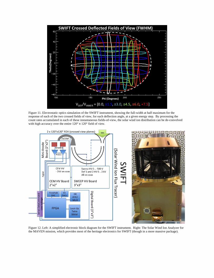
Figure 11. Electrostatic optics simulation of the SWIFT instrument, showing the full-width at half maximum for the
response of each of the two crossed fields of view, for each deflection angle, at a given energy step. By processing the
count rates accumulated in each of these instantaneous fields-of-view, the solar wind ion distribution can be de-convolved
with high accuracy over the entire 120° x 120° field of view.
Figure 12. Left: A simplified electronic block diagram for the SWIFT instrument. Right: The Solar Wind Ion Analyzer for
the MAVEN mission, which provides most of the heritage electronics for SWIFT (though in a more massive package).

3. MISSION ARCHITECTURE 1 – MOTHER-SHIP WITH CUBESAT DAUGHTERS
3.1 Planetary Hitchhiker
As discussed in the Introduction, we will review two mission architectures to deliver the Lunar Impactor cubesat on a
trajectory with the surface. First, we discuss an architecture that releases the cubesats from a mother-ship in lunar orbit.
To keep the cost of this architecture low, the mother-ship has been designed to be small enough to share a ride to
geostationary orbit (GTO) before making its way to the Moon. This mother-ship is therefore known as Planetary
Hitchhiker (PHH).
One of the major advantages of the PHH design is its compatibility with a variety of launch vehicles as a secondary
payload accommodation. Preeminent amongst those is the EELV Secondary Payload Adapter (ESPA) standard, which
can accommodate a 181 kg, 96 x 71 x 61 cm spacecraft. The current PHH concept at 96 kg (wet mass) and 86 x 65 x
44 cm is well within this envelope. In the nominal ESPA mission profile, the primary payload, which sits atop the ESPA
ring, separates at its intended injection orbit (herein assumed to be GTO). The EELV upper stage then performs a series
of orbital maneuvers in order to release up to six ESPA payloads at their proscribed initial orbits. Alternatively, an
innovative cost effective option involves packaging PHH within the spare battery compartment of a series 1300 Loral
communication satellite. This option is currently being studied further.
After PHH is placed into GTO by the launch vehicle, three apogee-raising burns totaling 800 m/s are performed by its
chemical propulsion system. Next, a burn must be performed to target the weak stability boundary (WSB) to put PHH on
a near-lunar trajectory, after which Lunar Orbit Insertion (LOI) takes place (Fig. 13). The WSB trajectory gives PHH the
flexibility to reach the Moon from any GTO orientation (with varying time) and requires less Δv, allowing for a range of
launch opportunities. Once in lunar orbit, station-keeping, orbital repositioning for nanosatellite impactor release, and a
deorbit burn will be performed using the propulsion system. The deorbit burn will take place at the end of useful
mission, near the end of propellant life, when the spacecraft will be maneuvered into a descent trajectory for impact on
the lunar surface. During the de-orbit descent, PHH can provide an additional opportunity for scientific measurements.
The PHH spacecraft contains a 6U cubesat dispenser that hosts the impactors, and accommodates any payload that
conforms to the published Cubesat Design Specification. The PHH spacecraft is comprised primarily of space-rated,
radiation-hardened parts (per GSFC EEE-INST-002) with components, assembled into a custom bus architecture. The
bus is 3-axis-stabilized with 1300 m/s of propulsion.
The avionics unit is a flight-proven design and is inherited from both the LCROSS and LADEE missions. Flight
software leverages LADEE heritage (with common-code reuse), using GSFC CFE/CFS as the core program. The
software STK and ODTK will be adopted for ground-based orbit determination. Three reaction wheels and an
accelerometer supplement the six attitude control system (ACS) thrusters for attitude control. Four coarse sun sensors
and a star tracker comprise the ACS sensor suite. Dual-frequency S-band helix antennas on the bus provide
communication with the Ames multi-mission operation center and deployable UHF antennas on the impactors allow
them to communicate with the mother-ship.
The PHH spacecraft has body-mounted solar panels (104 W capacity) to power a 24 A-h battery in addition to providing
structural support. Multi-layer insulation and surface coatings, along with several patch heaters, will be used for
spacecraft thermal control.
Excess tank capacity supports an additional 300 m/s ∆v, above the required 1300 m/s ∆v. A >6 dB link margin is
available at all phases using an 11 m antenna at UC Berkeley. The UHF crosslink between each cubesat impactor and the
spacecraft is 20 kbps and the downlink of science data from the spacecraft in lunar orbit to ground is 5.5 kbps. Figure 14
shows a drawing of the spacecraft, and Table 5 lists some of its properties.
Extensive lunar orbit modeling accounting for gravity perturbations was completed to validate the concept of operations
and maneuvers requiring minimal propulsive station keeping (highlights in Fig. 13). However, a detailed navigation and
attitude control error budget still must be assessed. Electrical interfaces and detailed ejection operations between the
Loral satellite and PHH must be defined before the battery compartment can be considered a viable launch option.
Finally, in order to keep spacecraft mass and launch cost low, a high density ISP monopropellant is required. Many
monopropellants have been studied in preparing the PHH design, but those with the highest performance typically
require higher development. Technology maturation of a high performance monopropellant is required in order to enable
the PHH mission without increasing complexity or mass.
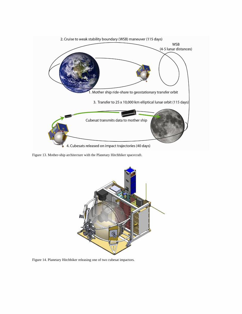
Figure 13. Mother-ship architecture with the Planetary Hitchhiker spacecraft.
Figure 14. Planetary Hitchhiker releasing one of two cubesat impactors.
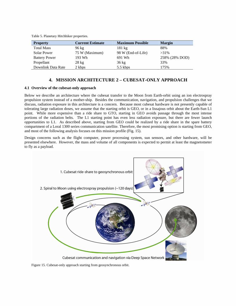
Table 5. Planetary Hitchhiker properties.
Property Current Estimate Maximum Possible Margin
Total Mass 96 kg 181 kg 88%
Solar Power 75 W (Maximum) 98 W (End-of-Life) >31%
Battery Power 193 Wh 691 Wh 258% (28% DOD)
Propellant 28 kg 36 kg 33%
Downlink Data Rate 2 kbps 5.5 kbps 175%
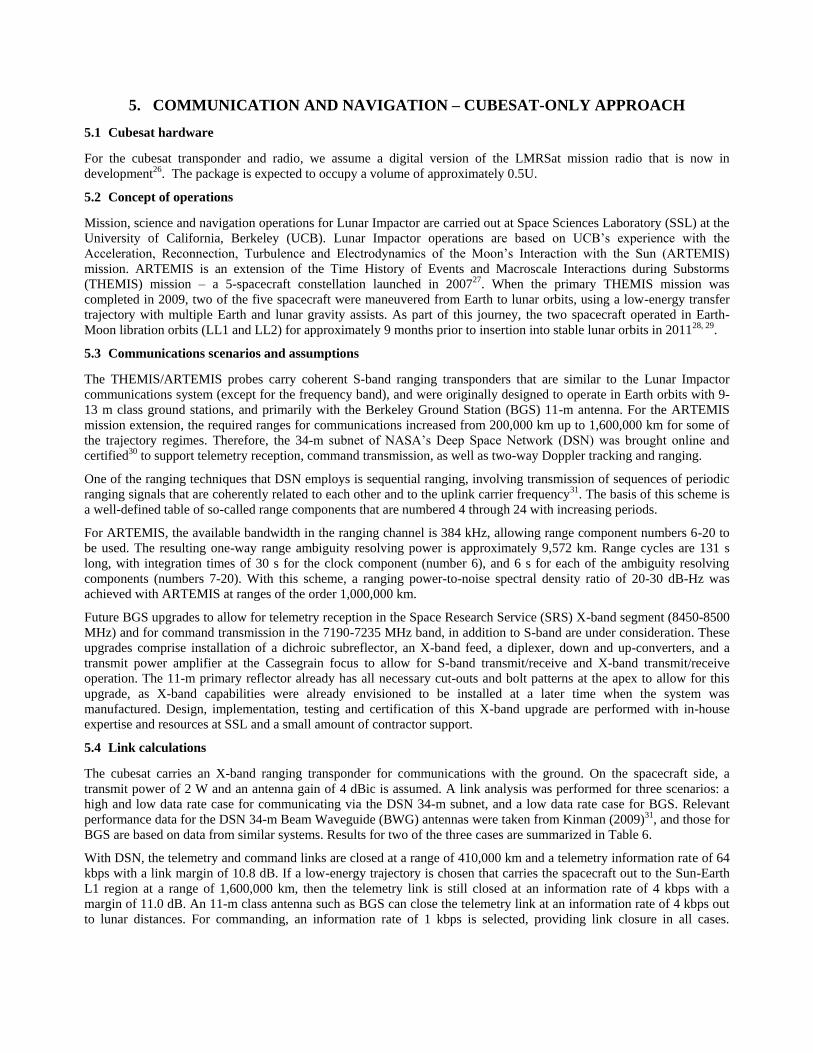
4. MISSION ARCHITECTURE 2 – CUBESAT-ONLY APPROACH
4.1 Overview of the cubesat-only approach
Below we describe an architecture where the cubesat transfer to the Moon from Earth-orbit using an ion electrospray
propulsion system instead of a mother-ship. Besides the communication, navigation, and propulsion challenges that we
discuss, radiation exposure in this architecture is a concern. Because most cubesat hardware is not presently capable of
tolerating large radiation doses, we assume that the starting orbit is GEO, or in a lissajous orbit about the Earth-Sun L1
point. While more expensive than a ride share to GTO, starting in GEO avoids passage through the most intense
portions of the radiation belts. The L1 starting point has even less radiation exposure, but there are fewer launch
opportunities to L1. As described above, starting from GEO could be realized by a ride share in the spare battery
compartment of a Loral 1300 series communication satellite. Therefore, the most promising option is starting from GEO,
and most of the following analysis focuses on this mission profile (Fig. 15).
Design concerns such as the flight computer, power processing system, sun sensors, and other hardware, will be
presented elsewhere. However, the mass and volume of all components is expected to permit at least the magnetometer
to fly as a payload.
Figure 15. Cubesat-only approach starting from geosynchronous orbit.
5. COMMUNICATION AND NAVIGATION – CUBESAT-ONLY APPROACH
5.1 Cubesat hardware
For the cubesat transponder and radio, we assume a digital version of the LMRSat mission radio that is now in
development26. The package is expected to occupy a volume of approximately 0.5U.
5.2 Concept of operations
Mission, science and navigation operations for Lunar Impactor are carried out at Space Sciences Laboratory (SSL) at the
University of California, Berkeley (UCB). Lunar Impactor operations are based on UCB’s experience with the
Acceleration, Reconnection, Turbulence and Electrodynamics of the Moon’s Interaction with the Sun (ARTEMIS)
mission. ARTEMIS is an extension of the Time History of Events and Macroscale Interactions during Substorms
(THEMIS) mission – a 5-spacecraft constellation launched in 200727. When the primary THEMIS mission was
completed in 2009, two of the five spacecraft were maneuvered from Earth to lunar orbits, using a low-energy transfer
trajectory with multiple Earth and lunar gravity assists. As part of this journey, the two spacecraft operated in Earth-
Moon libration orbits (LL1 and LL2) for approximately 9 months prior to insertion into stable lunar orbits in 201128, 29.
5.3 Communications scenarios and assumptions
The THEMIS/ARTEMIS probes carry coherent S-band ranging transponders that are similar to the Lunar Impactor
communications system (except for the frequency band), and were originally designed to operate in Earth orbits with 9-
13 m class ground stations, and primarily with the Berkeley Ground Station (BGS) 11-m antenna. For the ARTEMIS
mission extension, the required ranges for communications increased from 200,000 km up to 1,600,000 km for some of
the trajectory regimes. Therefore, the 34-m subnet of NASA’s Deep Space Network (DSN) was brought online and
certified30 to support telemetry reception, command transmission, as well as two-way Doppler tracking and ranging.
One of the ranging techniques that DSN employs is sequential ranging, involving transmission of sequences of periodic
ranging signals that are coherently related to each other and to the uplink carrier frequency31. The basis of this scheme is
a well-defined table of so-called range components that are numbered 4 through 24 with increasing periods.
For ARTEMIS, the available bandwidth in the ranging channel is 384 kHz, allowing range component numbers 6-20 to
be used. The resulting one-way range ambiguity resolving power is approximately 9,572 km. Range cycles are 131 s
long, with integration times of 30 s for the clock component (number 6), and 6 s for each of the ambiguity resolving
components (numbers 7-20). With this scheme, a ranging power-to-noise spectral density ratio of 20-30 dB-Hz was
achieved with ARTEMIS at ranges of the order 1,000,000 km.
Future BGS upgrades to allow for telemetry reception in the Space Research Service (SRS) X-band segment (8450-8500
MHz) and for command transmission in the 7190-7235 MHz band, in addition to S-band are under consideration. These
upgrades comprise installation of a dichroic subreflector, an X-band feed, a diplexer, down and up-converters, and a
transmit power amplifier at the Cassegrain focus to allow for S-band transmit/receive and X-band transmit/receive
operation. The 11-m primary reflector already has all necessary cut-outs and bolt patterns at the apex to allow for this
upgrade, as X-band capabilities were already envisioned to be installed at a later time when the system was
manufactured. Design, implementation, testing and certification of this X-band upgrade are performed with in-house
expertise and resources at SSL and a small amount of contractor support.
5.4 Link calculations
The cubesat carries an X-band ranging transponder for communications with the ground. On the spacecraft side, a
transmit power of 2 W and an antenna gain of 4 dBic is assumed. A link analysis was performed for three scenarios: a
high and low data rate case for communicating via the DSN 34-m subnet, and a low data rate case for BGS. Relevant
performance data for the DSN 34-m Beam Waveguide (BWG) antennas were taken from Kinman (2009)31, and those for
BGS are based on data from similar systems. Results for two of the three cases are summarized in Table 6.
With DSN, the telemetry and command links are closed at a range of 410,000 km and a telemetry information rate of 64
kbps with a link margin of 10.8 dB. If a low-energy trajectory is chosen that carries the spacecraft out to the Sun-Earth
L1 region at a range of 1,600,000 km, then the telemetry link is still closed at an information rate of 4 kbps with a
margin of 11.0 dB. An 11-m class antenna such as BGS can close the telemetry link at an information rate of 4 kbps out
to lunar distances. For commanding, an information rate of 1 kbps is selected, providing link closure in all cases.
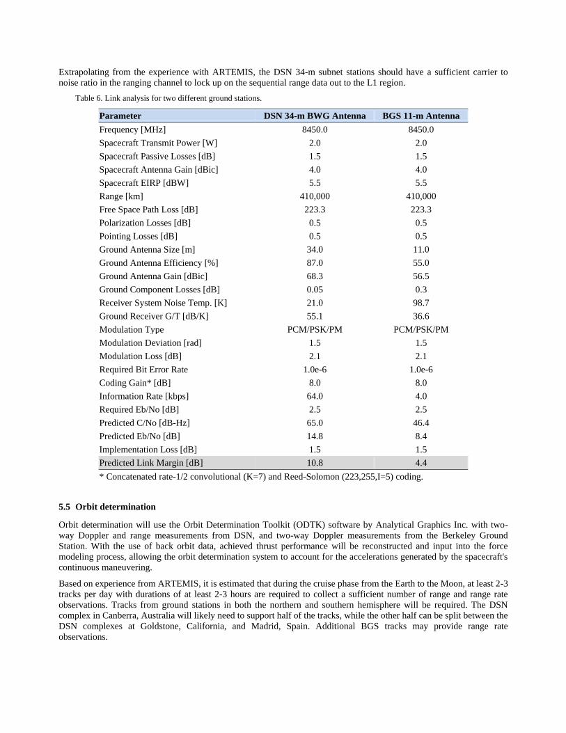
Extrapolating from the experience with ARTEMIS, the DSN 34-m subnet stations should have a sufficient carrier to
noise ratio in the ranging channel to lock up on the sequential range data out to the L1 region.
Table 6. Link analysis for two different ground stations.
Parameter DSN 34-m BWG Antenna BGS 11-m Antenna
Frequency [MHz] 8450.0 8450.0
Spacecraft Transmit Power [W] 2.0 2.0
Spacecraft Passive Losses [dB] 1.5 1.5
Spacecraft Antenna Gain [dBic] 4.0 4.0
Spacecraft EIRP [dBW] 5.5 5.5
Range [km] 410,000 410,000
Free Space Path Loss [dB] 223.3 223.3
Polarization Losses [dB] 0.5 0.5
Pointing Losses [dB] 0.5 0.5
Ground Antenna Size [m] 34.0 11.0
Ground Antenna Efficiency [%] 87.0 55.0
Ground Antenna Gain [dBic] 68.3 56.5
Ground Component Losses [dB] 0.05 0.3
Receiver System Noise Temp. [K] 21.0 98.7
Ground Receiver G/T [dB/K] 55.1 36.6
Modulation Type PCM/PSK/PM PCM/PSK/PM
Modulation Deviation [rad] 1.5 1.5
Modulation Loss [dB] 2.1 2.1
Required Bit Error Rate 1.0e-6 1.0e-6
Coding Gain* [dB] 8.0 8.0
Information Rate [kbps] 64.0 4.0
Required Eb/No [dB] 2.5 2.5
Predicted C/No [dB-Hz] 65.0 46.4
Predicted Eb/No [dB] 14.8 8.4
Implementation Loss [dB] 1.5 1.5
Predicted Link Margin [dB] 10.8 4.4
* Concatenated rate-1/2 convolutional (K=7) and Reed-Solomon (223,255,I=5) coding.
5.5 Orbit determination
Orbit determination will use the Orbit Determination Toolkit (ODTK) software by Analytical Graphics Inc. with two-
way Doppler and range measurements from DSN, and two-way Doppler measurements from the Berkeley Ground
Station. With the use of back orbit data, achieved thrust performance will be reconstructed and input into the force
modeling process, allowing the orbit determination system to account for the accelerations generated by the spacecraft's
continuous maneuvering.
Based on experience from ARTEMIS, it is estimated that during the cruise phase from the Earth to the Moon, at least 2-3
tracks per day with durations of at least 2-3 hours are required to collect a sufficient number of range and range rate
observations. Tracks from ground stations in both the northern and southern hemisphere will be required. The DSN
complex in Canberra, Australia will likely need to support half of the tracks, while the other half can be split between the
DSN complexes at Goldstone, California, and Madrid, Spain. Additional BGS tracks may provide range rate
observations.
5.6 Discussion of trades, complexities and challenges
Future work includes development of more detailed scenarios to determine the achievable navigation accuracy as a
function of thrust performance, attitude stability, as well as number and duration of ground station tracks. Most of the
operations related complexities will arise from the fact that thrusting needs to be taken into account for the orbit
determination process. Given the high level of DSN resource contention, it will also be difficult to find sufficient
tracking time to support Lunar Impactor navigation operations with the required accuracy.
5.7 Qualitative assessment of results
It will be challenging to determine the mission trajectories with the required accuracy in the presence of quasi-
continuous thrusting, as it depends on the stability of both the thrust performance and the attitude control system. For
conventional orbit determination, the trajectory arcs are divided into thrust and thrust-free sections. For Lunar Impactor
this will not be possible, so accurate force modeling needs to be included in the differential correction process for orbit
determination. The concept of operations will need to allow for navigation planning and data processing in a forward
rolling manner. Experience and lessons learned from NASA’s Dawn mission that featured quasi-continuous thrusting
with an ion propulsion system should be applicable to Lunar Impactor.
6. PROPULSION SYSTEM – CUBESAT-ONLY APPROACH
6.1 Propulsion system background
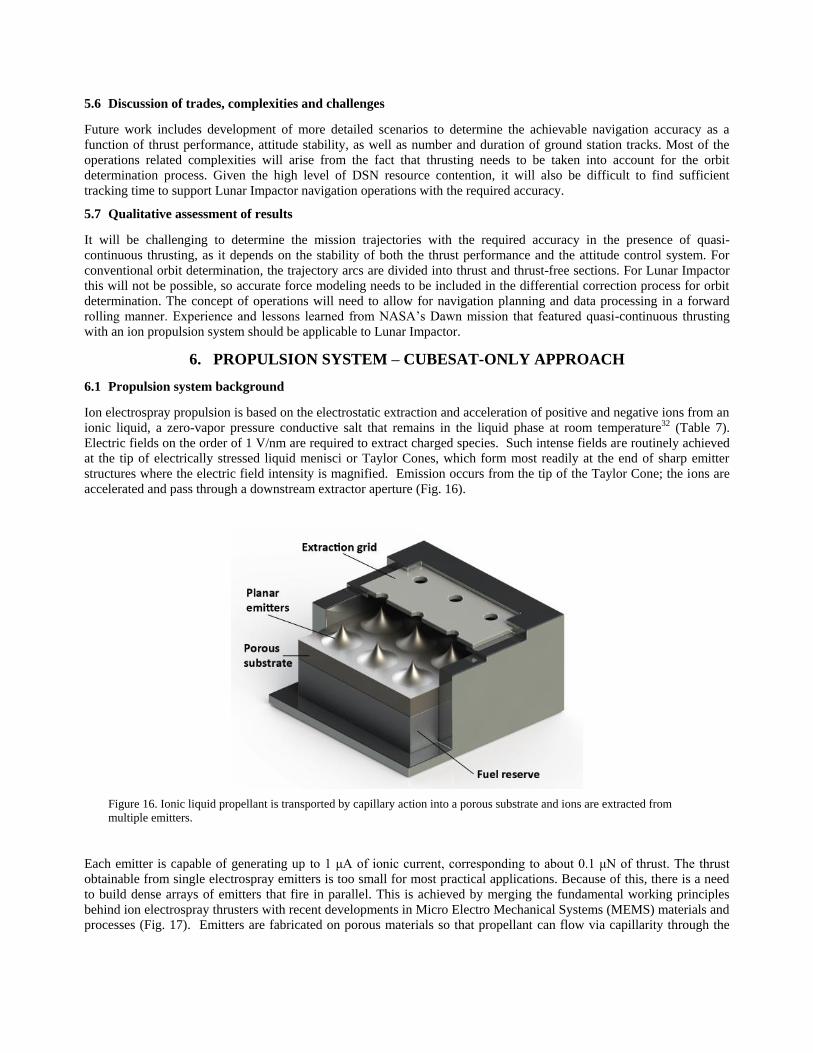
Ion electrospray propulsion is based on the electrostatic extraction and acceleration of positive and negative ions from an
ionic liquid, a zero-vapor pressure conductive salt that remains in the liquid phase at room temperature32 (Table 7).
Electric fields on the order of 1 V/nm are required to extract charged species. Such intense fields are routinely achieved
at the tip of electrically stressed liquid menisci or Taylor Cones, which form most readily at the end of sharp emitter
structures where the electric field intensity is magnified. Emission occurs from the tip of the Taylor Cone; the ions are
accelerated and pass through a downstream extractor aperture (Fig. 16).
Figure 16. Ionic liquid propellant is transported by capillary action into a porous substrate and ions are extracted from
multiple emitters.
Each emitter is capable of generating up to 1 μA of ionic current, corresponding to about 0.1 μN of thrust. The thrust
obtainable from single electrospray emitters is too small for most practical applications. Because of this, there is a need
to build dense arrays of emitters that fire in parallel. This is achieved by merging the fundamental working principles
behind ion electrospray thrusters with recent developments in Micro Electro Mechanical Systems (MEMS) materials and
processes (Fig. 17). Emitters are fabricated on porous materials so that propellant can flow via capillarity through the
bulk of the material, driven by the ion evaporation process (Fig. 16). Therefore, no pressurization is required for
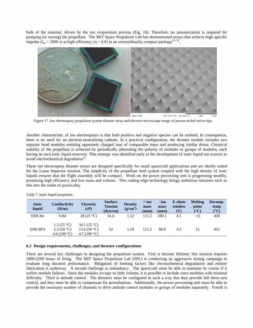
pumping (or storing) the propellant. The MIT Space Propulsion Lab has demonstrated arrays that achieve high specific
impulse (Isp > 2000 s) at high efficiency (η > 0.8) in an extraordinarily compact package33, 34.
Figure 17. Ion electrospray propulsion system thruster array and electron microscope image of porous nickel micro-tips.
Another characteristic of ion electrosprays is that both positive and negative species can be emitted. In consequence,
there is no need for an electron-neutralizing cathode. In a practical configuration, the thruster module includes two
separate head modules emitting oppositely charged ions of comparable mass and producing similar thrust. Chemical
stability of the propellant is achieved by periodically alternating the polarity of modules or groups of modules, each
having its own ionic liquid reservoir. This strategy was identified early in the development of ionic liquid ion sources to
avoid electrochemical degradation32.
These ion electrospray thruster arrays are designed specifically for small spacecraft applications and are ideally suited
for the Lunar Impactor mission. The simplicity of the propellant feed system coupled with the high density of ionic
liquids ensures that the flight assembly will be compact. Work on the power processing unit is progressing steadily,
promising high efficiency and low mass and volume. This cutting edge technology brings ambitious missions such as
this into the realm of practicality.
Table 7. Ionic liquid properties.
Ionic
liquid
Conductivity
(Si/m)
Viscosity
(cP)
Surface
Tension
(dyn/cm)
Density
(g/cm3)
+ ion
mass
(amu)
- ion
mass
(amu)
E-chem
window
(V)
Melting
point
(°C)
Decomp.
temp
(°C)
EMI-Im 0.84 28 (25 °C) 41.6 1.52 111.2 280.1 4.1 -15 450
EMI-BF4
1.3 (25 °C)
2.3 (50 °C)
4.6 (100 °C)
34.1 (25 °C)
15.6 (50 °C)
4.7 (100 °C)
52 1.24 111.2 86.8 4.5 12 412
6.2 Design requirements, challenges, and thruster configurations
There are several key challenges in designing the propulsion system. First is thruster lifetime; this mission requires
1800-2200 hours of firing. The MIT Space Propulsion Lab (SPL) is conducting an aggressive testing campaign to
evaluate long duration performance. Mitigation of limiting factors like electrochemical degradation and emitter
fabrication is underway. A second challenge is redundancy. The spacecraft must be able to maintain its course if it
suffers module failures. Since the modules occupy so little volume, it is possible to include extra modules with minimal
difficulty. Third is attitude control. The thrusters must be configured in such a way that they provide full three-axis
control, and they must be able to compensate for perturbations. Additionally, the power processing unit must be able to
provide the necessary number of channels to drive attitude control modules or groups of modules separately. Fourth is
radiation mitigation. Starting in GEO reduces radiation belt concerns, but the electronics, particularly the power
processing unit (PPU), must be able to survive the cis-lunar environment. A radiation-hardened version of the PPU is
under study and key components of the Precision Electrospray Thruster Assembly (PETA) unit discussed below can be
procured in hardened versions. Fifth is sizing; mass and volume are severely constrained in a 3U cubesat. The high
density of ionic liquids and the simplicity of the propellant feed and storage system offer unparalleled performance.
Optimization of specific impulse, propellant mass, and other properties will occur when the mass of the payload and bus
are more fully defined. A 10% Δv margin will be included to account for unplanned course and attitude corrections.
Thruster geometry is a major design consideration. The propulsion system must be compact, easy to integrate with the
rest of the bus, and provide adequate forces and torques for three-axis control. An example from which the Lunar
Impactor propulsion system can be derived is the PETA unit built for the iEPS thrusters under a NASA Phase II SBIR
with Espace Inc. in collaboration with MIT SPL. The PETA PPU boards are designed to fit within a cubesat format to
facilitate their testing and operations on the small platforms.
The cubesat-sized PETA engineering model (EM) PPU is shown in the left of Fig. 18, with one thruster-pair and its
associated tanks (each ~1 cc in volume) on the far right corner of the board. This PETA unit has two-boards and
supports two channels (to switch on or off two independent groups of thrusters). The locations for seven more thruster
pairs are outlined on the board. The unit has a mass of 125 g when integrated with four thruster pairs and loaded
propellant tanks. Each thruster pair can be configured to either thrust normal to the board, or laterally.
Shown on the right side of Fig. 18 is a three-board/six-channel PETA prototype model (PM) PPU that can provide pitch,
yaw, roll and thrust control with 8 thruster pairs (16 thruster modules and tanks). The PPU power requirement depends
on the commanded thrust level, and is limited to about 5 W, to fit within reasonable cubesat power budgets. The thruster
assembly with a total of about 20 g of propellant provides a total of 200 m/s to a 3 kg nanosat.
The Lunar Impactor baseline requirements differ in terms of propellant mass (~400 g, Section 7) and maximum power
budget (~30 W). Fortunately, the current high-voltage board design is scalable and can be upgraded to 30 W using
COTS components up-rated for higher power operations with lay-out modifications to accommodate part foot-prints and
the higher currents and heat dissipation, which is minimized by a high conversion efficiency. The required total tank
volume is about 330 cc (~0.3U).
To provide attitude control on Lunar Impactor, a four-channel two-board configuration using the two “bottom” PETA
PM boards independently driving four lateral micro-thruster pairs (with tanks) can provide pitch, yaw and roll authority.
Four independent lateral thruster pairs can be configured, for example, on one diagonal of the engineering model board
shown in Fig. 18 to provide pure “roll” torque, and pitch / yaw authorities (with some linear thrust). (Another possible
thruster configuration with similar capabilities using some “normal” thruster pairs is shown in the notional Fig 19.) A
higher power board, coupled with a switch/thruster-tank interface board can separately handle the higher thrust primary
propulsion. The attitude control and primary propulsion assemblies can be separated on the platform. Primary
propulsion is provided by a separate cluster of thruster modules mounted on the base panel, and these are all serviced by
two larger propellant tanks (to enable positive and negative polarities to be fired at the same time). As many arrays will
be mounted on the base as possible, since this would minimize the current flowing through each individual thruster,
thereby minimizing wear and also permitting thruster failures. Current prototype modules have a thrust density of 25
µN/cm2, meaning 64 cm2 of area (32 modules) is required to achieve the desired thrust of approximately 1-2 mN
(Section 7). The available area on the base is approximately 80 cm2, such that 8 extra modules can be included for
redundancy. Thrust density is expected to double or triple in subsequent thruster models, meaning redundancy can be
greatly increased. This configuration minimizes complexity as well as volume. As a whole, the derived four-board and
thruster-tank configuration providing attitude control and primary propulsion would occupy a total of ~750 cc, or ~3/4U,
with a mass of ~ 650 g.

Figure 18. Left: Two-board engineering model. Right: Three-board prototype model, the lower portion of which would
comprise the Lunar Impactor propulsion module power processing unit.
Figure 19. One notional thruster configuration for main propulsion and three-axis attitude control. The flight unit will have
many more modules on the base panel for primary propulsion.
7. TRAJECTORY ANALYSIS – CUBESAT-ONLY APPROACH
7.1 Simulations
Ion electrospray propulsion is highly efficient, but given the power constraints aboard the spacecraft, the thrust is very
low. Maneuvers must be performed over long periods, and analysis methods for more traditional impulsive burns are
not useful. Analytical solutions for low-thrust spacecraft trajectories can only be found in very limited cases; numerical
simulation is the preferred method. The Astrogator module in STK is the tool of choice given its flexibility. All cases
analyzed in the following section assume that the target point is the Reiner Gamma magnetic anomaly. It is also
assumed that the initial wet mass of the cubesat is 5 kg and the specific impulse achieved is 2400 seconds.
Three initial conditions are considered: GEO, GTO, and Earth-Sun L1. For the GEO and GTO cases, both steady and
variable thrust is simulated. Steady thrust represents a constant power supply to the thrusters (22.2 W after losses
Thruster pair
Thruster pair with tank EM
PM
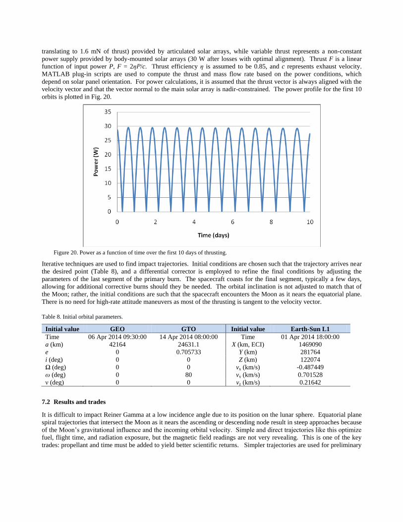
translating to 1.6 mN of thrust) provided by articulated solar arrays, while variable thrust represents a non-constant
power supply provided by body-mounted solar arrays (30 W after losses with optimal alignment). Thrust F is a linear
function of input power P, F = 2ηP/c. Thrust efficiency η is assumed to be 0.85, and c represents exhaust velocity.
MATLAB plug-in scripts are used to compute the thrust and mass flow rate based on the power conditions, which
depend on solar panel orientation. For power calculations, it is assumed that the thrust vector is always aligned with the
velocity vector and that the vector normal to the main solar array is nadir-constrained. The power profile for the first 10
orbits is plotted in Fig. 20.
Figure 20. Power as a function of time over the first 10 days of thrusting.
Iterative techniques are used to find impact trajectories. Initial conditions are chosen such that the trajectory arrives near
the desired point (Table 8), and a differential corrector is employed to refine the final conditions by adjusting the
parameters of the last segment of the primary burn. The spacecraft coasts for the final segment, typically a few days,
allowing for additional corrective burns should they be needed. The orbital inclination is not adjusted to match that of
the Moon; rather, the initial conditions are such that the spacecraft encounters the Moon as it nears the equatorial plane.
There is no need for high-rate attitude maneuvers as most of the thrusting is tangent to the velocity vector.
Table 8. Initial orbital parameters.
Initial value GEO GTO Initial value Earth-Sun L1
Time 06 Apr 2014 09:30:00 14 Apr 2014 08:00:00 Time 01 Apr 2014 18:00:00
a (km) 42164 24631.1 X (km, ECI) 1469090
e 0 0.705733 Y (km) 281764
i (deg) 0 0 Z (km) 122074
Ω (deg) 0 0 vx (km/s) -0.487449
ω (deg) 0 80 vy (km/s) 0.701528
ν (deg) 0 0 vz (km/s) 0.21642
7.2 Results and trades
It is difficult to impact Reiner Gamma at a low incidence angle due to its position on the lunar sphere. Equatorial plane
spiral trajectories that intersect the Moon as it nears the ascending or descending node result in steep approaches because
of the Moon’s gravitational influence and the incoming orbital velocity. Simple and direct trajectories like this optimize
fuel, flight time, and radiation exposure, but the magnetic field readings are not very revealing. This is one of the key
trades: propellant and time must be added to yield better scientific returns. Simpler trajectories are used for preliminary

analysis, but much attention is being paid to the examination of more aggressive flight plans to ensure that the incidence
angle is low.
Increasing the demand on the propulsion system must be carefully considered. Greater Δv means longer firing times and
higher probability of failure. The ion electrospray propulsion system will be flown in space before this mission occurs,
but it will not be flight tested for the duration required by the Lunar Impactor. Longer flight time also means higher
radiation exposure, which is already a concern.
The results obtained in the simulations are listed in Table 9. Note that these are preliminary, and the spacecraft does not
have any form of feedback control. They are not optimized either; they meet basic mission objectives. Figures 21-23
show graphical representations of the GEO to Reiner Gamma trajectories.
It is evident that the GTO to Reiner Gamma cases are far more demanding on the propulsion system; this coupled with
dozens of passes through the radiation belts makes it an unattractive option. In these cases, the spacecraft is powered
down while transiting the most intense regions of the radiation belts. One must also note that using body-mounted
arrays does not increase the flight time by unreasonable amounts. It has minimal impact on Δv and propellant usage as
well.
Compensating for environmental perturbations is also a major consideration. Aside from gravitational forces, solar
radiation pressure will have the most substantial effect. A rudimentary model is included in the current simulations, and
this will be refined as the project continues. This model characterizes drift, but torques must be computed separately.
Assuming a worst case center-of-pressure/center-of-gravity offset of 5 cm and a solar array area of 0.15 m, a torque of
6.86 x 10⁻⁸ Nm is applied (GEO to Reiner Gamma body-mounted array case). A single thruster module can provide
torque on the order of 3 x 10⁻⁵ Nm depending on its configuration. Assuming constant countering of this torque by the
thrusters over the course of the whole trajectory, a total Δv less than 1 m/s is required.
Attitude knowledge and control is a key driver of performance. Star trackers for cubesats are massive and occupy a
large volume, so sun sensors are the primary option. However, they are less accurate, meaning thrust vector
misalignment is likely to be greater. This will be thoroughly examined and characterized as work progresses.
Preliminarily though, assuming a constant 2° thrust misalignment due to sensing errors, a total Δv of approximately 60
m/s is required for course corrections over the entire trajectory (GEO to Reiner Gamma body-mounted array case).
Future refinements to the trajectory simulations include incorporating pauses in thruster firing when in contact with the
DSN and optimizing for incidence angle and radiation exposure. The optimal propellant mass fraction and specific
impulse will be computed when the spacecraft mass is better defined. Robust simulations incorporating error and
feedback control will be developed.
Table 9. Trajectory simulation results.
Initial Orbit Solar Array Type Time of Flight
(days)
Propellant
Consumed (grams)
Δv (km/s)
GEO* Body-mounted 104 392 1.922
GEO* Articulated 72 390 1.912
GTO Body-mounted 172 624 3.138
GTO Articulated 119 620 3.116
Earth-Sun L1 Articulated 74 134 0.639 *Primary option studied in this paper.

Figure 21. Trajectory from GEO to lunar impact. Blue and yellow segments are coasting periods.
Figure 22. Geometry of the trajectory from GEO to lunar impact, as viewed from the Earth.

Figure 23. Close-up of the impact at Reiner Gamma, as viewed from an Earth-centered frame.
8. CONCLUSIONS
Our work shows that Lunar Impactor would perform important new measurements at lunar magnetic anomalies. The
flight of such a mission will soon be feasible. For the cubesat-only approach, some of the technical challenges ahead
include: 1) Long duration testing of the ion electrospray propulsion system, 2) Radiation mitigation techniques, 3)
Refinement of the plan for accurate navigation to the Moon, and 4) Finding trajectories that impact the lunar surface at
low angles, to maximize the science return. All of these challenges are surmountable and are being actively addressed.
When Lunar Impactor is ready to fly, it will be a highly versatile platform capable of performing other near-Earth
missions, such as unique observations of the magnetosphere and close-approaching asteroids.
ACKNOWLEDGEMENTS
This paper is dedicated to Bob Lin, our friend and mentor. This research was performed as part of the World Class
University Project at Kyung Hee University, and sponsored by the Korean Ministry of Education, Science and
Technology. IGB also thanks the Hellman Family Foundation for a Hellman Fellowship. We thank Clyde Space for
permission to use their cubesat graphic in Figs. 3, 13 and 15. Authors are listed alphabetically after BAJ.
REFERENCES
[1] Fuller, M., and Cisowski, S. M., “Lunar paleomagnetism,” Geomagnetism, 2, 307-455 (1987).
[2] Wieczorek, M. A., Jolliff, B. L., Khan, A. et al., “The constitution and structure of the lunar interior,” Rev.
Mineral. Geochem., 60, 221-364 (2006).
[3] Garrick-Bethell, I., Weiss, B. P., Shuster, D. L. et al., “Early lunar magnetism,” Science, 323, 356-359 (2009).
[4] Shea, E. K., Weiss, B. P., Cassata, W. S. et al., “A long-lived lunar core dynamo,” Science, 335, 453-456
(2012).

[5] Dwyer, C. A., Stevenson, D. J., and Nimmo, F., “A long-lived lunar dynamo driven by continuous mechanical
stirring,” Nature, 470, 212-214 (2011).
[6] Le Bars, M., Wieczorek, M., Karatekin, O. et al., “An impact-driven dynamo for the early Moon,” Nature, 479,
215-218 (2011).
[7] Hood, L. L., and Artemieva, N. A., “Antipodal effects of lunar basin-forming impacts: Initial 3-D simulations
and comparisons with observations,” Icarus, 193, 485-502 (2008).
[8] Hood, L. L., and Schubert, G., “Lunar magnetic anomalies and surface optical properties,” Science, 208, 49-51
(1980).
[9] Hemingway, D., and Garrick-Bethell, I., “Magnetic field direction and lunar swirl morphology: Insights from
Airy and Reiner Gamma,” J. Geophys. Res., 117, E10012 (2012).
[10] Hapke, B., “Space weathering from Mercury to the Asteroid Belt,” J. Geophys. Res., 106, 10039-10073 (2001).
[11] Criswell, D. R., “Lunar dust motion,” Proc. Lunar Sci. Conf. 3rd, 2671-2680 (1972).
[12] Colwell, J. E., Robertson, S. R., Horányi, M. et al., “Lunar dust levitation,” J. Aero. Eng., 22, 2-9 (2009).
[13] Garrick-Bethell, I., Head, J. W., and Pieters, C. M., “Magnetic fields, spectral properties, and dust transport at
lunar swirls,” Icarus, 212, 480-492 (2011).
[14] Kramer, G. Y., Besse, S., Dhingra, D. et al., “M3 spectral analysis of lunar swirls and the link between optical
maturation and surface hydroxyl formation at magnetic anomalies,” J. Geophy. Res., 116, E00G18 (2011).
[15] Pieters, C. M., Goswami, J. N., Clark, R. N. et al., “Character and Spatial Distribution of OH/H2O on the
Surface of the Moon Seen by M3 on Chandrayaan-1 ” Science, 326(5952), 568-572 (2009).
[16] Saito, Y., Yokota, S., Tanaka, T. et al., “Solar wind proton reflection at the lunar surface: Low energy ion
measurement by MAP-PACE onboard SELENE (KAGUYA),” Geophys. Res. Lett., 35, L24205 (2009).
[17] Saito, Y., Nishino, M. N., Fujimoto, M. et al., “Simultaneous observation of the electron acceleration and ion
deceleration over lunar magnetic anomalies,” Earth Planets Space, 64, 83-92 (2012).
[18] Poppe, A. R., Halekas, J., Delory, G. T. et al., “Particle in cell simulations of the solar wind interaction with
lunar crustal magnetic anomalies: Magnetic cusp regions,” J. Geophy. Res., 117, A09105 (2012).
[19] Purucker, M., and Nichols, J., “Global spherical harmonic models of the internal magnetic field of the Moon
based on sequential and coestimation approaches,” J. Geophys. Res., 115, E12007 (2010).
[20] Stutzke, N., Russek, S. E., Pappas, D. P. et al., “Low frequency noise measurements on commercial
magnetoresistive magnetic field sensors ” J. Appl. Phys. , 97 10Q107 (2005).
[21] Carr, C., “The Double Star magnetic field investigation: Overview of instrument performance and initial
results,” Ann. Geophys., 23, 2713-2732. (2005).
[22] Lee, Y., Jin, H., Seon, J. et al., “Development of CubeSat for space science mission: CINEMA,” Proc. 62nd
International Astronautical Congress, paper IAC-11-B4.2.5 (2011).
[23] Liu, L.-Y., Jiang, S.-B., Yeh, T.-L. et al., “The Magneto-Resistive Magnetometer of BCU on the Tatiana-2
Satellite,” Terrestrial, Atmospheric and Oceanic Sciences, 23.3, 70-79 (2012).
[24] Brown, P., Beek, T., Carr, C. et al., “Magnetoresistive magnetometer for space science applications ” Meas.
Sci. Tech., 23, 025902 (2012).
[25] Sanz, R., Fernandez, A. B., Dominguez, J. A. et al., “Gamma Irradiation of Magnetoresistive Sensors for
Planetary Exploration,” Sensors, 12, 4447-4465 (2012).
[26] Duncan, C. B., “Low Mass Radio Science Transponder - Navigation Anywhere,” Proc. iCubeSat 2012
Interplanetary CubeSat Workshop, Paper C.3.2 (2012).
[27] Bester, M., Lewis, M., Roberts, B. et al., “Multi-mission Flight Operations at UC Berkeley – Experiences and
Lessons Learned,” Proc. AIAA SpaceOps Conference, Paper AIAA-2010-2198 (2010).
[28] Cosgrove, D., Frey, S., Folta, D. et al., “Navigating THEMIS to the ARTEMIS Low-Energy Lunar Transfer
Trajectory,” Proc. AIAA SpaceOps Conference Paper AIAA-2010-2352 (2010).
[29] Cosgrove, D., Owens, B., Marchese, J. et al., “ARTEMIS Operations from Earth-Moon Libration Orbits to
Stable Lunar Orbits,” Proc. AIAA SpaceOps Conference, Paper AIAA 2012-1296179 (2012).
[30] Roberts, B., Lewis, M., Thorsness, J. et al., “THEMIS Mission Networks Expansion – Adding the Deep Space
Network for the ARTEMIS Lunar Mission Phase,” AIAA SpaceOps Conference, Paper AIAA-2010-1934
(2010).
[31] Kinman, P. W., [Deep Space Network Telecommunications Link Design Handbook, 810-005, Revision E]
NASA Jet Propulsion Laboratory, Pasadena, CA(2009).
[32] Lozano, P., “Ionic Liquid Ion Sources: Suppression of Electrochemical Reactions using Voltage Alternation,”
Journal of Colloid and Interface Science, 280(1), 149-154 (2004).

[33] Legge, R. S., and Lozano, P., “Electrospray Propulsion Based on Emitters Microfabricated in Porous Metals,”
Journal of Propulsion and Power, 27(2), 485-495 (2011).
[34] Courtney, D., and Lozano, P., “Electrochemical Micromachining on Porous Nickel for Arrays of Electrospray
Ion Emitters,” Journal of Microelectromechanical Systems, 22(2), 471-482 (2012).