lync server 2013 using sip trunk to cisco unified ... · pdf filelync server 2013 using sip...
TRANSCRIPT

© 2014 Cisco Systems, Inc. All rights reserved. Important notices, privacy statements, and trademarks of Cisco Systems, Inc. can be found on cisco.com
Page 1 of 111
Lync Server 2013 using SIP trunk to Cisco Unified
Communications Manager Release 10.0
Application Note
Application Note
© 2014 Cisco Systems, Inc. All rights reserved. Important notices, privacy statements, and trademarks of Cisco Systems, Inc. can be found on cisco.com
Page 2 of 111
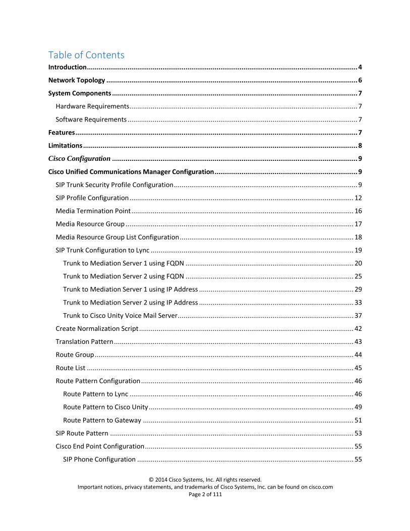
Table of Contents Introduction ............................................................................................................................................ 4
Network Topology .................................................................................................................................. 6
System Components ............................................................................................................................... 7
Hardware Requirements ...................................................................................................................... 7
Software Requirements ....................................................................................................................... 7
Features .................................................................................................................................................. 7
Limitations .............................................................................................................................................. 8
Cisco Configuration ............................................................................................................................... 9
Cisco Unified Communications Manager Configuration .......................................................................... 9
SIP Trunk Security Profile Configuration ............................................................................................... 9
SIP Profile Configuration .................................................................................................................... 12
Media Termination Point ................................................................................................................... 16
Media Resource Group ...................................................................................................................... 17
Media Resource Group List Configuration .......................................................................................... 18
SIP Trunk Configuration to Lync ......................................................................................................... 19
Trunk to Mediation Server 1 using FQDN ....................................................................................... 20
Trunk to Mediation Server 2 using FQDN ....................................................................................... 25
Trunk to Mediation Server 1 using IP Address ................................................................................ 29
Trunk to Mediation Server 2 using IP Address ................................................................................ 33
Trunk to Cisco Unity Voice Mail Server ........................................................................................... 37
Create Normalization Script ............................................................................................................... 42
Translation Pattern ............................................................................................................................ 43
Route Group ...................................................................................................................................... 44
Route List .......................................................................................................................................... 45
Route Pattern Configuration .............................................................................................................. 46
Route Pattern to Lync .................................................................................................................... 46
Route Pattern to Cisco Unity .......................................................................................................... 49
Route Pattern to Gateway ............................................................................................................. 51
SIP Route Pattern .............................................................................................................................. 53
Cisco End Point Configuration ............................................................................................................ 55
SIP Phone Configuration ................................................................................................................ 55

© 2014 Cisco Systems, Inc. All rights reserved. Important notices, privacy statements, and trademarks of Cisco Systems, Inc. can be found on cisco.com
Page 3 of 111
SCCP Phone Configuration ............................................................................................................. 66
MGCP Gateway Configuration ........................................................................................................... 74
Voice Mail Pilot Configuration ........................................................................................................... 80
Cisco Unity Voice Mail Server Configuration ......................................................................................... 81
Phone System Configuration .............................................................................................................. 81
Port Group Configuration .................................................................................................................. 82
Port Configuration ............................................................................................................................. 83
Cisco Unity User Configuration .......................................................................................................... 84
Cisco User Configuration ................................................................................................................ 84
Lync User Configuration ................................................................................................................. 86
Gateway Configuration ......................................................................................................................... 88
Cisco Router[External IOS MTP] Configuration ..................................................................................... 92
Lync Server Configuration ..................................................................................................................... 93
Add CISCO UCM to Lync Topology...................................................................................................... 93
Trunk Configuration ........................................................................................................................... 98
Route .............................................................................................................................................. 101
Voice Policy and PSTN Usage ........................................................................................................... 102
Dial Plan .......................................................................................................................................... 105
Configure Media Bypass .................................................................................................................. 110
Configure Encryption Level .............................................................................................................. 111

© 2014 Cisco Systems, Inc. All rights reserved. Important notices, privacy statements, and trademarks of Cisco Systems, Inc. can be found on cisco.com
Page 4 of 111
Introduction This document describes the steps and configurations necessary for Cisco Unified Communications
Manager (Cisco UCM) release 10.0 to interoperate with the Lync Server 2013 using SIP. End points are
configured on both Cisco UCM and Lync Server with connectivity to PSTN. A SIP Trunk is configured
between Cisco UCM and Cisco Unity for Voicemail connectivity, Lync Server users access Cisco Unity
Voicemail via Cisco UCM.
Key Points:
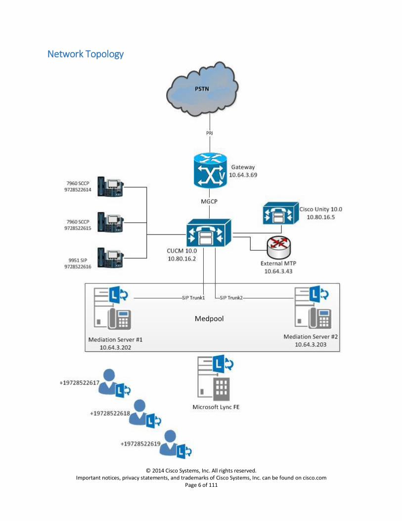
The testing has been performed with only IPv4 using TCP for signaling.
CISCO UCM is connected to the PSTN network via MGCP Gateway, as seen in the topology diagram.
Basic call, call transfer with and without refer, call forwarding, conference call, call hold and resume, call park, RTCP, PRACK, Voice Mail work successfully.
Testing was performed with Cisco UCM 10.0(1), but a later release fixing the defects CSCum00523 and CSCun13435 is required to resolve REFER and Call Hold issues.
A Lua script is used to modify the bandwidth line during call hold, to manipulate the user=phone parameter in SIP URIs, to change History-Info headers in inbound INVITEs to Diversion headers, to change Referred-By headers to Diversion headers and to provide ring back at the call originator when PRACK is enabled on the SIP trunk.
An external MTP is used on CISCO UCM to enable RTCP from CISCO UCM.
“IP RTCP Interval threshold” on MGCP gateway is changed to 5000 to prevent Lync from dropping the call while the call is on hold with MOH enabled.
Configuration of multiple SIP trunks and associated routing in Cisco UCM is necessary to support redundant Lync Mediation servers.
The following items were tested:
Basic outbound and inbound calls between Lync and PSTN through Unified Communications Manager and verification of voice path.
SIP Headers: E.164 and non-E.164, phone-context, long Request-URI
Anonymous caller representation
Codecs: G.711ulaw, G.711alaw, DTMF, Comfort Noise
Early Media: PRACK, IVR
RTP and RTCP
Call transfer: attended, early unattended (only for Cisco endpoints) and blind (only for Lync endpoints).
© 2014 Cisco Systems, Inc. All rights reserved. Important notices, privacy statements, and trademarks of Cisco Systems, Inc. can be found on cisco.com
Page 5 of 111
Call Park and retrieve
Shared Lines on Cisco endpoints.
Call forwarding: Call Forward Unconditional (CFU), simultaneous ring, Call Forward No Answer, Call Forward Busy (only for Cisco endpoints)
Hold and resume with music on hold and without music on hold.
Three-way conferencing
Voice Mail
© 2014 Cisco Systems, Inc. All rights reserved. Important notices, privacy statements, and trademarks of Cisco Systems, Inc. can be found on cisco.com
Page 6 of 111
Network Topology
© 2014 Cisco Systems, Inc. All rights reserved. Important notices, privacy statements, and trademarks of Cisco Systems, Inc. can be found on cisco.com
Page 7 of 111
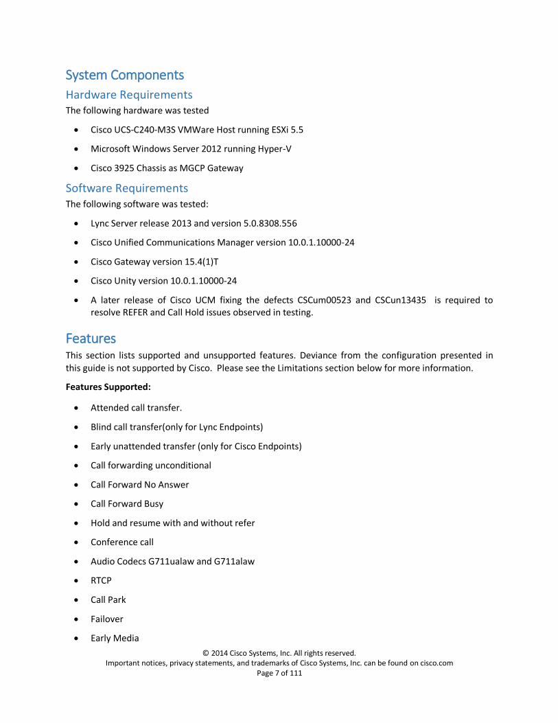
System Components
Hardware Requirements The following hardware was tested
Cisco UCS-C240-M3S VMWare Host running ESXi 5.5
Microsoft Windows Server 2012 running Hyper-V
Cisco 3925 Chassis as MGCP Gateway
Software Requirements The following software was tested:
Lync Server release 2013 and version 5.0.8308.556
Cisco Unified Communications Manager version 10.0.1.10000-24
Cisco Gateway version 15.4(1)T
Cisco Unity version 10.0.1.10000-24
A later release of Cisco UCM fixing the defects CSCum00523 and CSCun13435 is required to resolve REFER and Call Hold issues observed in testing.
Features This section lists supported and unsupported features. Deviance from the configuration presented in
this guide is not supported by Cisco. Please see the Limitations section below for more information.
Features Supported:
Attended call transfer.
Blind call transfer(only for Lync Endpoints)
Early unattended transfer (only for Cisco Endpoints)
Call forwarding unconditional
Call Forward No Answer
Call Forward Busy
Hold and resume with and without refer
Conference call
Audio Codecs G711ualaw and G711alaw
RTCP
Call Park
Failover
Early Media

© 2014 Cisco Systems, Inc. All rights reserved. Important notices, privacy statements, and trademarks of Cisco Systems, Inc. can be found on cisco.com
Page 8 of 111
MWI on Cisco Phones
Shared lines on Cisco Endpoints
Voice Mail Deposit and Retrieval
Message Waiting Indicator (only for Cisco Endpoints)
Features Not Supported or Not Tested:
Message Waiting Indicator on Lync Endpoints
Limitations These are the known limitations, caveats, or integration issues:
When simultaneous ring is set on Lync client to an IVR and PSTN user makes an inbound call to Lync, the call originator does not hear the early media from IVR.
No message waiting indicator on Lync for voice mail. Lync rejects the NOTIFY from Unity as it does not have ‘Notify’ as either Supported or Allowed on the call leg to Unity
Lync users do not receive Comfort Noise. Cisco provides local Comfort Noise via Cisco IP Phones and Gateways
The external MTP configured on Unified Communications Manager does not pass-through the RTCP packets coming from Lync or the MGCP Gateway when it receives a=inactive in the SDP on call hold from Lync.
When Unified Communications Manager and external MTP are configured for G.729 only and if it receives a call with G.711, Unified Communications Manager sends back a “503 Service Unavailable”

© 2014 Cisco Systems, Inc. All rights reserved. Important notices, privacy statements, and trademarks of Cisco Systems, Inc. can be found on cisco.com
Page 9 of 111
Cisco Configuration The goal of this guide is to provide an overview of the integration between Cisco Unified Communication
Manager, Cisco Unity and Lync Server. The deployment will interconnect the UC systems using SIP and
using MGCP Gateway for PSTN connectivity to Unified Communications Manager. The following
sections provide the required configurations for a successful integration.
Cisco Unified Communications Manager Configuration
SIP Trunk Security Profile Configuration Navigation: System -> Security -> SIP Trunk Security Profile
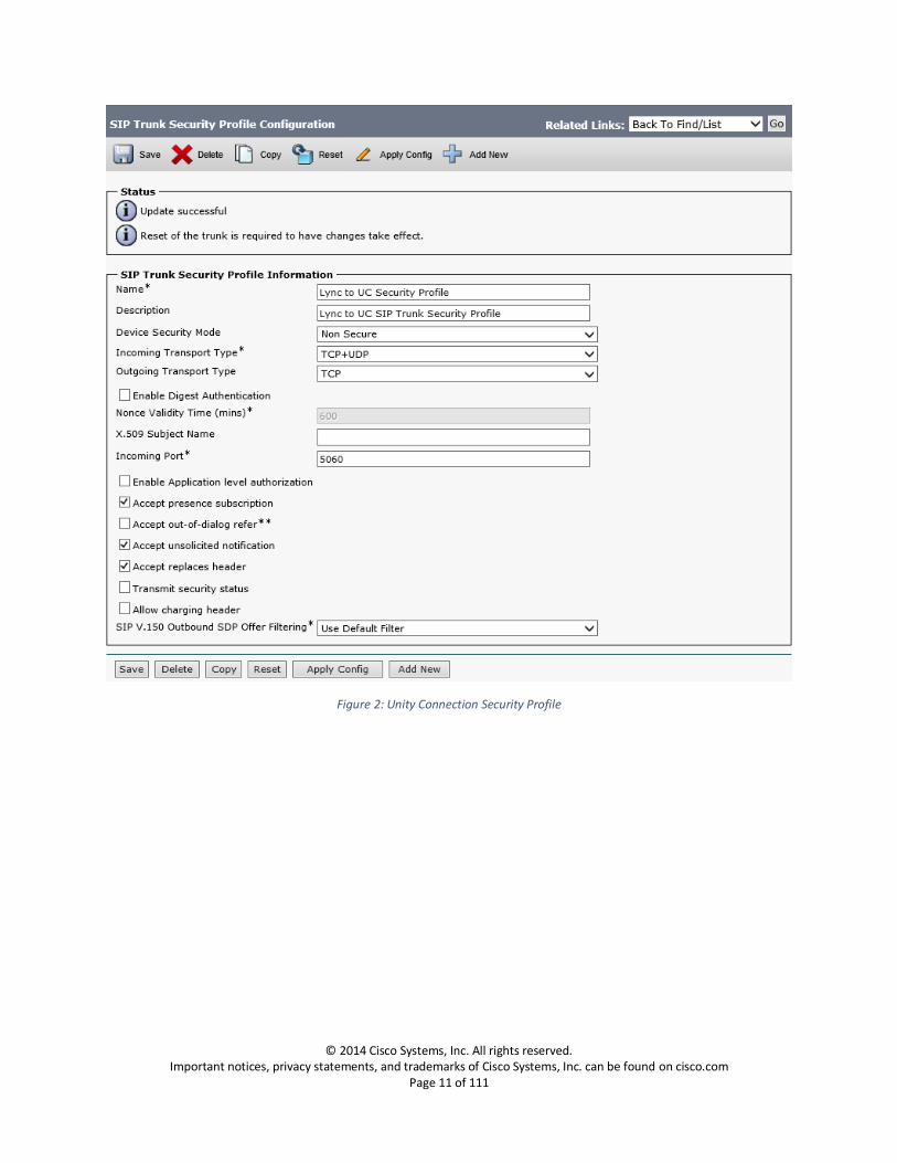
1. Set Name: Enter a name for the security profile. When you save the new profile, the name displays in the SIP Trunk Security Profile drop-down list box in the Trunk Configuration window.
2. Set Description: Enter a description relevant to your security profile
3. Confirm Accept unsolicited notification: is checked
If you want Cisco Unified Communications Manager to accept incoming non-INVITE, unsolicited notification messages that come via the SIP trunk, check this check box.
4. Confirm Accept replaces header: is checked
If you want Cisco Unified Communications Manager to accept new SIP dialogs, which have replaced existing SIP dialogs, check this check box

© 2014 Cisco Systems, Inc. All rights reserved. Important notices, privacy statements, and trademarks of Cisco Systems, Inc. can be found on cisco.com
Page 10 of 111
Figure 1: SIP Trunk Security Profile
© 2014 Cisco Systems, Inc. All rights reserved. Important notices, privacy statements, and trademarks of Cisco Systems, Inc. can be found on cisco.com
Page 11 of 111
Figure 2: Unity Connection Security Profile
© 2014 Cisco Systems, Inc. All rights reserved. Important notices, privacy statements, and trademarks of Cisco Systems, Inc. can be found on cisco.com
Page 12 of 111
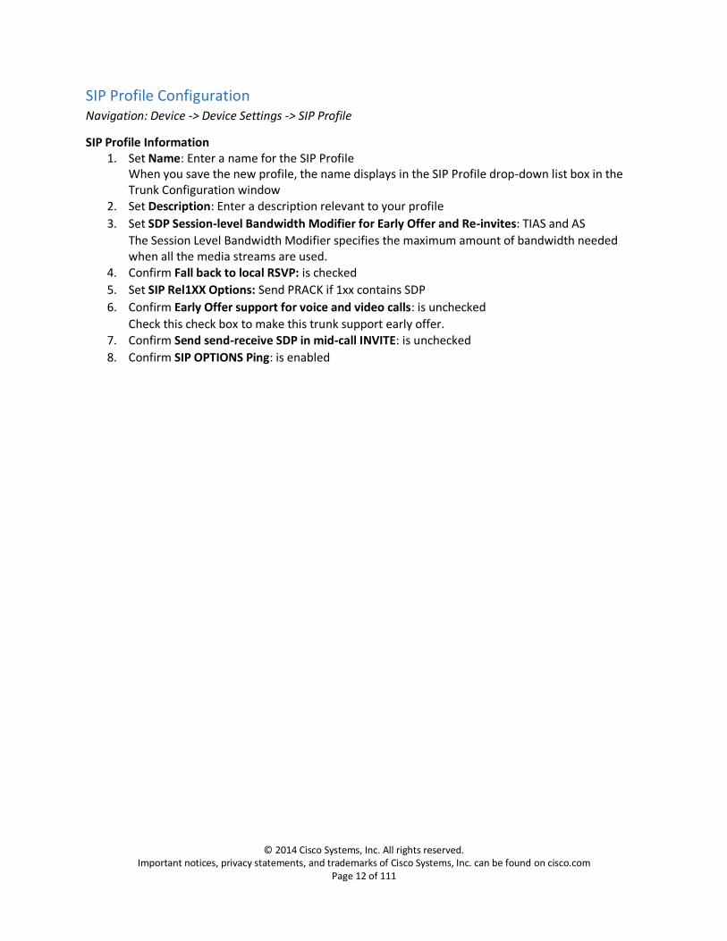
SIP Profile Configuration Navigation: Device -> Device Settings -> SIP Profile
SIP Profile Information 1. Set Name: Enter a name for the SIP Profile
When you save the new profile, the name displays in the SIP Profile drop-down list box in the Trunk Configuration window
2. Set Description: Enter a description relevant to your profile
3. Set SDP Session-level Bandwidth Modifier for Early Offer and Re-invites: TIAS and AS
The Session Level Bandwidth Modifier specifies the maximum amount of bandwidth needed when all the media streams are used.
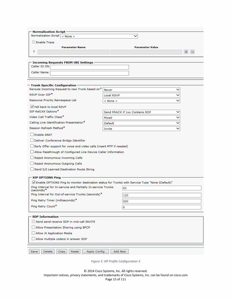
4. Confirm Fall back to local RSVP: is checked
5. Set SIP Rel1XX Options: Send PRACK if 1xx contains SDP
6. Confirm Early Offer support for voice and video calls: is unchecked
Check this check box to make this trunk support early offer. 7. Confirm Send send-receive SDP in mid-call INVITE: is unchecked
8. Confirm SIP OPTIONS Ping: is enabled

© 2014 Cisco Systems, Inc. All rights reserved. Important notices, privacy statements, and trademarks of Cisco Systems, Inc. can be found on cisco.com
Page 13 of 111
Figure 3: SIP Profile Configuration -1

© 2014 Cisco Systems, Inc. All rights reserved. Important notices, privacy statements, and trademarks of Cisco Systems, Inc. can be found on cisco.com
Page 14 of 111
Figure 4: SIP Profile Configuration-2
© 2014 Cisco Systems, Inc. All rights reserved. Important notices, privacy statements, and trademarks of Cisco Systems, Inc. can be found on cisco.com
Page 15 of 111
Figure 5: SIP Profile Configuration-3

© 2014 Cisco Systems, Inc. All rights reserved. Important notices, privacy statements, and trademarks of Cisco Systems, Inc. can be found on cisco.com
Page 16 of 111
Media Termination Point Navigation: Media Resources->Media Termination Point
1. Set Media Termination Point Name: Enter the name of the external media termination point
2. Set Device Pool: Select the device pool, default device pool is used in this configuration.
Figure 6: Media Termination Point-1
3. Confirm, the configured MTP is registered with the Unified Communications Manager
Figure 7: Media Termination Point-2

© 2014 Cisco Systems, Inc. All rights reserved. Important notices, privacy statements, and trademarks of Cisco Systems, Inc. can be found on cisco.com
Page 17 of 111
Media Resource Group Navigation: Media Resources -> Media Resource Group
1. Add New Media Resource Group
2. Set Name: Enter a name for this group
3. Add Resources: Select the available resources as shown in the screen capture below.
Figure 8: Media Resource Group Configuration
© 2014 Cisco Systems, Inc. All rights reserved. Important notices, privacy statements, and trademarks of Cisco Systems, Inc. can be found on cisco.com
Page 18 of 111
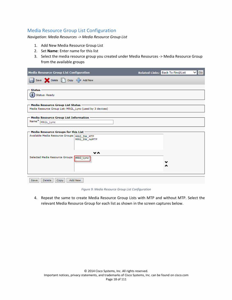
Media Resource Group List Configuration Navigation: Media Resources -> Media Resource Group List
1. Add New Media Resource Group List
2. Set Name: Enter name for this list
3. Select the media resource group you created under Media Resources -> Media Resource Group
from the available groups
Figure 9: Media Resource Group List Configuration
4. Repeat the same to create Media Resource Group Lists with MTP and without MTP. Select the
relevant Media Resource Group for each list as shown in the screen captures below.

© 2014 Cisco Systems, Inc. All rights reserved. Important notices, privacy statements, and trademarks of Cisco Systems, Inc. can be found on cisco.com
Page 19 of 111
SIP Trunk Configuration to Lync Navigation: Device -> Trunk
Trunks are created from Unified Communications Manager to each Lync Mediation Server for trunk
failover and also to enable communications between Cisco UCM and Lync Mediation Servers. The
FQDNs are used for configuring the trunks to the Lync Mediation Servers. However, due to the current
limitation on Cisco UCM, if a SIP trunk is associated to a SIP-Route Pattern, the same trunks is not
available to be included in a Route-List. This creates a need for a duplicate set of trunks to each Lync
Mediation Server using IPv4 address. This makes the total number of trunks required to be four (two
trunks using FQDN and two trunks using IP) to enable the provisioning of Route List and SIP Route
Patterns to the Lync Mediation Servers.
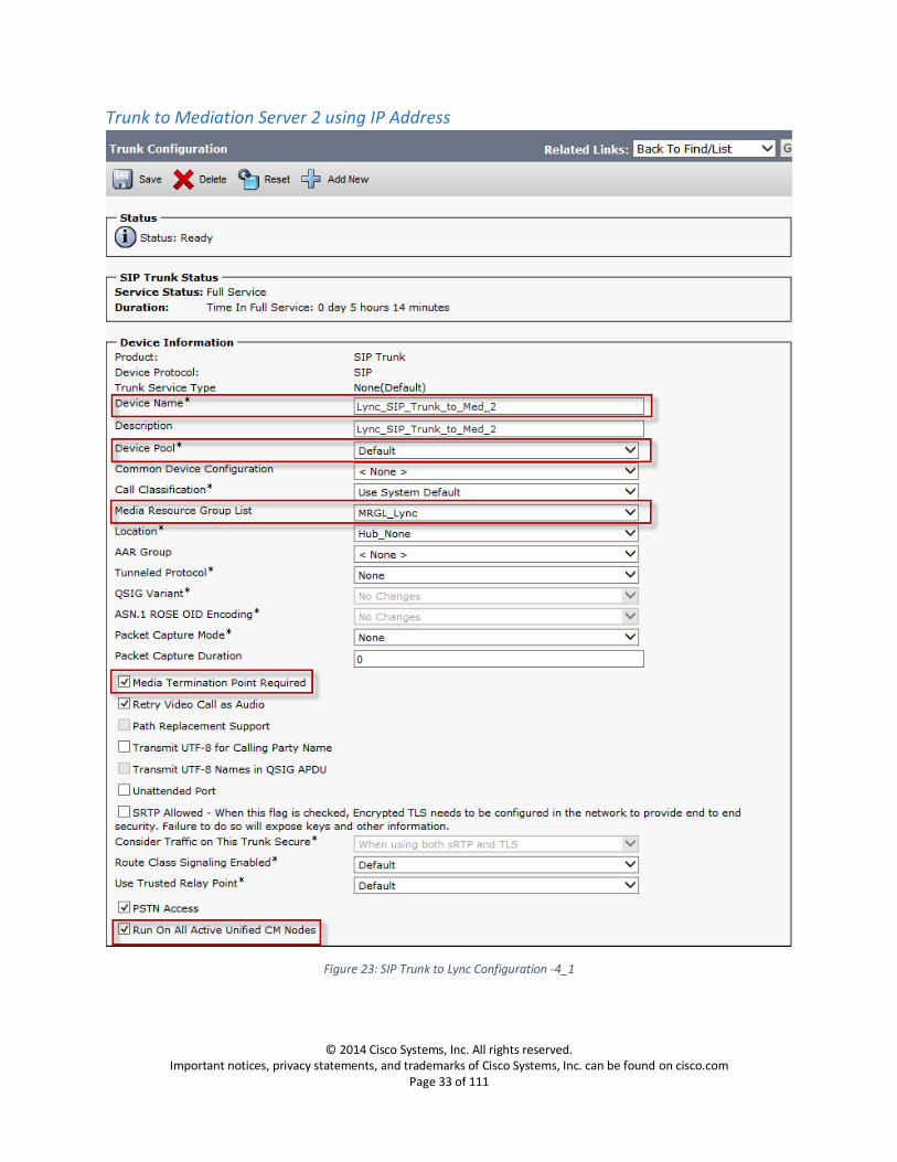
Device Information 1. Set Trunk Type: SIP Trunk 2. Set Device Protocol: SIP
3. Set Trunk Service Type: None
4. Set Device Name: Enter a name for the trunk
5. Set Description: Enter a description relevant to your trunk
6. Set Device Pool: Default
For trunks, device pools specify a list of Cisco Unified Communications Managers that the trunk uses to distribute the call load dynamically
7. Set Media Resource Group List: MRGL_Lync, this is the list you created under
Media Resources -> Media Resource Group List. This list provides a prioritized grouping of media resource groups. An application chooses the required media resource, such as a Music on Hold server, from among the available media resources according to the priority order that a Media Resource Group List defines.
8. Confirm Media Termination Point Required: is checked
This check box is used to indicate whether a media termination point (MTP) is used to implement features that H.323 does not support (such as hold and transfer).
9. Confirm Retry Video Calls as Audio: is checked
10. Confirm Run On All Active Unified CM Nodes: is checked
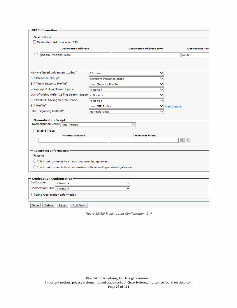
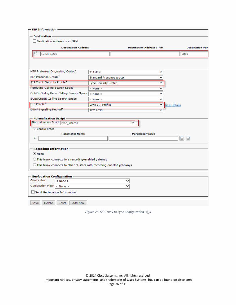
SIP Information 11. Set the Destination Address: Enter the FQDN of the Mediation Server to which you are
establishing a trunk.
12. Set SIP trunk Security Profile: Select the security profile you created under System -> Security ->
SIP Security Profile
13. Set SIP Profile: Select the SIP Profile you created under Device -> Device Settings -> SIP Profile
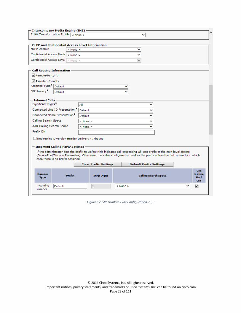
14. Set Normalization Script: Select the normalization script to modify the bandwidth line b=CT:64
during call hold, ring back issue with PRACK enabled.

© 2014 Cisco Systems, Inc. All rights reserved. Important notices, privacy statements, and trademarks of Cisco Systems, Inc. can be found on cisco.com
Page 20 of 111
Trunk to Mediation Server 1 using FQDN
Figure 10: SIP Trunk to Lync Configuration -1_1

© 2014 Cisco Systems, Inc. All rights reserved. Important notices, privacy statements, and trademarks of Cisco Systems, Inc. can be found on cisco.com
Page 21 of 111
Figure 11: SIP Trunk to Lync Configuration -1_2
© 2014 Cisco Systems, Inc. All rights reserved. Important notices, privacy statements, and trademarks of Cisco Systems, Inc. can be found on cisco.com
Page 22 of 111
Figure 12: SIP Trunk to Lync Configuration -1_3

© 2014 Cisco Systems, Inc. All rights reserved. Important notices, privacy statements, and trademarks of Cisco Systems, Inc. can be found on cisco.com
Page 23 of 111
Figure 13: SIP Trunk to Lync Configuration -1_4

© 2014 Cisco Systems, Inc. All rights reserved. Important notices, privacy statements, and trademarks of Cisco Systems, Inc. can be found on cisco.com
Page 24 of 111
Figure 14: SIP Trunk to Lync Configuration -1_5

© 2014 Cisco Systems, Inc. All rights reserved. Important notices, privacy statements, and trademarks of Cisco Systems, Inc. can be found on cisco.com
Page 25 of 111
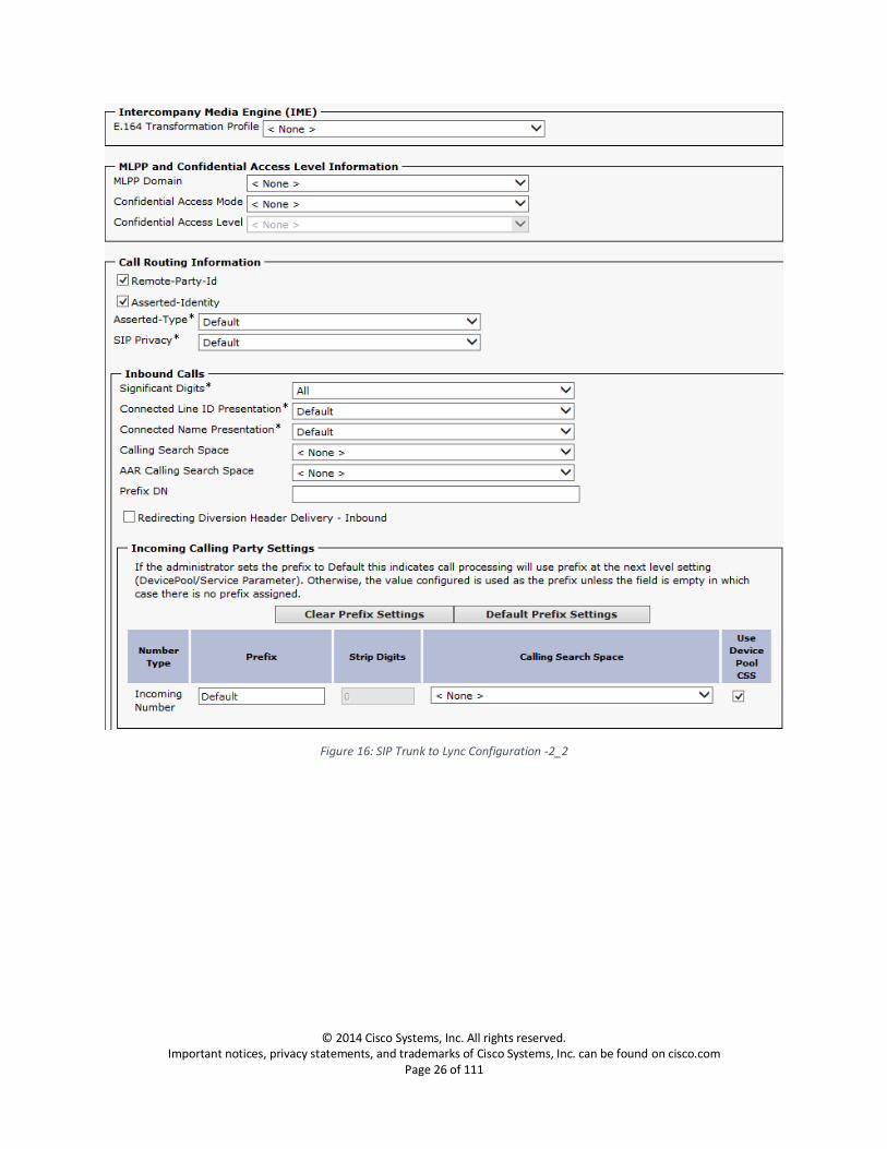
Trunk to Mediation Server 2 using FQDN
Figure 15: SIP Trunk to Lync Configuration -2_1
© 2014 Cisco Systems, Inc. All rights reserved. Important notices, privacy statements, and trademarks of Cisco Systems, Inc. can be found on cisco.com
Page 26 of 111
Figure 16: SIP Trunk to Lync Configuration -2_2

© 2014 Cisco Systems, Inc. All rights reserved. Important notices, privacy statements, and trademarks of Cisco Systems, Inc. can be found on cisco.com
Page 27 of 111
Figure 17: SIP Trunk to Lync Configuration -2_3
© 2014 Cisco Systems, Inc. All rights reserved. Important notices, privacy statements, and trademarks of Cisco Systems, Inc. can be found on cisco.com
Page 28 of 111
Figure 18: SIP Trunk to Lync Configuration -2_4

© 2014 Cisco Systems, Inc. All rights reserved. Important notices, privacy statements, and trademarks of Cisco Systems, Inc. can be found on cisco.com
Page 29 of 111
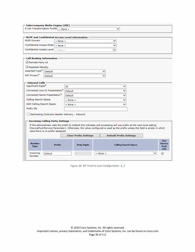
Trunk to Mediation Server 1 using IP Address
Figure 19: SIP Trunk to Lync Configuration -3_1
© 2014 Cisco Systems, Inc. All rights reserved. Important notices, privacy statements, and trademarks of Cisco Systems, Inc. can be found on cisco.com
Page 30 of 111
Figure 20: SIP Trunk to Lync Configuration -3_2

© 2014 Cisco Systems, Inc. All rights reserved. Important notices, privacy statements, and trademarks of Cisco Systems, Inc. can be found on cisco.com
Page 31 of 111
Figure 21: SIP Trunk to Lync Configuration -3_3

© 2014 Cisco Systems, Inc. All rights reserved. Important notices, privacy statements, and trademarks of Cisco Systems, Inc. can be found on cisco.com
Page 32 of 111
Figure 22: SIP Trunk to Lync Configuration -3_4
© 2014 Cisco Systems, Inc. All rights reserved. Important notices, privacy statements, and trademarks of Cisco Systems, Inc. can be found on cisco.com
Page 33 of 111
Trunk to Mediation Server 2 using IP Address
Figure 23: SIP Trunk to Lync Configuration -4_1

© 2014 Cisco Systems, Inc. All rights reserved. Important notices, privacy statements, and trademarks of Cisco Systems, Inc. can be found on cisco.com
Page 34 of 111
Figure 24: SIP Trunk to Lync Configuration -4_2

© 2014 Cisco Systems, Inc. All rights reserved. Important notices, privacy statements, and trademarks of Cisco Systems, Inc. can be found on cisco.com
Page 35 of 111
Figure 25: SIP Trunk to Lync Configuration -4_3
© 2014 Cisco Systems, Inc. All rights reserved. Important notices, privacy statements, and trademarks of Cisco Systems, Inc. can be found on cisco.com
Page 36 of 111
Figure 26: SIP Trunk to Lync Configuration -4_4
© 2014 Cisco Systems, Inc. All rights reserved. Important notices, privacy statements, and trademarks of Cisco Systems, Inc. can be found on cisco.com
Page 37 of 111
Trunk to Cisco Unity Voice Mail Server Navigation: Device -> Trunk
The following procedure describes the trunk configuration from Unified Communications Manager to
Cisco Unity Voice Mail Server
Device Information 1. Set Trunk Type: SIP Trunk 2. Set Device Protocol: SIP
3. Set Trunk Service Type: None
4. Set Device Name: Enter a name for the trunk
5. Set Description: Enter a description relevant to your trunk
6. Set Device Pool: Default
For trunks, device pools specify a list of Cisco Unified Communications Managers that the trunk uses to distribute the call load dynamically
7. Confirm Media Termination Point Required: is checked
This check box is used to indicate whether a media termination point (MTP) is used to implement features that H.323 does not support (such as hold and transfer).
8. Confirm Retry Video Calls as Audio: is checked
SIP Information 9. Set the Destination Address: Enter the FQDN/IP Address of the Unity Server to which you are
establishing a trunk.
10. Set SIP trunk Security Profile: Select the security profile you created under System -> Security ->
SIP Security Profile

© 2014 Cisco Systems, Inc. All rights reserved. Important notices, privacy statements, and trademarks of Cisco Systems, Inc. can be found on cisco.com
Page 38 of 111
Figure 27: SIP Trunk to Cisco Unity-1

© 2014 Cisco Systems, Inc. All rights reserved. Important notices, privacy statements, and trademarks of Cisco Systems, Inc. can be found on cisco.com
Page 39 of 111
Figure 28: SIP Trunk to Cisco Unity-2

© 2014 Cisco Systems, Inc. All rights reserved. Important notices, privacy statements, and trademarks of Cisco Systems, Inc. can be found on cisco.com
Page 40 of 111
Figure 29: SIP Trunk to Cisco Unity-3

© 2014 Cisco Systems, Inc. All rights reserved. Important notices, privacy statements, and trademarks of Cisco Systems, Inc. can be found on cisco.com
Page 41 of 111
Figure 30: SIP Trunk to Cisco Unity-4
© 2014 Cisco Systems, Inc. All rights reserved. Important notices, privacy statements, and trademarks of Cisco Systems, Inc. can be found on cisco.com
Page 42 of 111
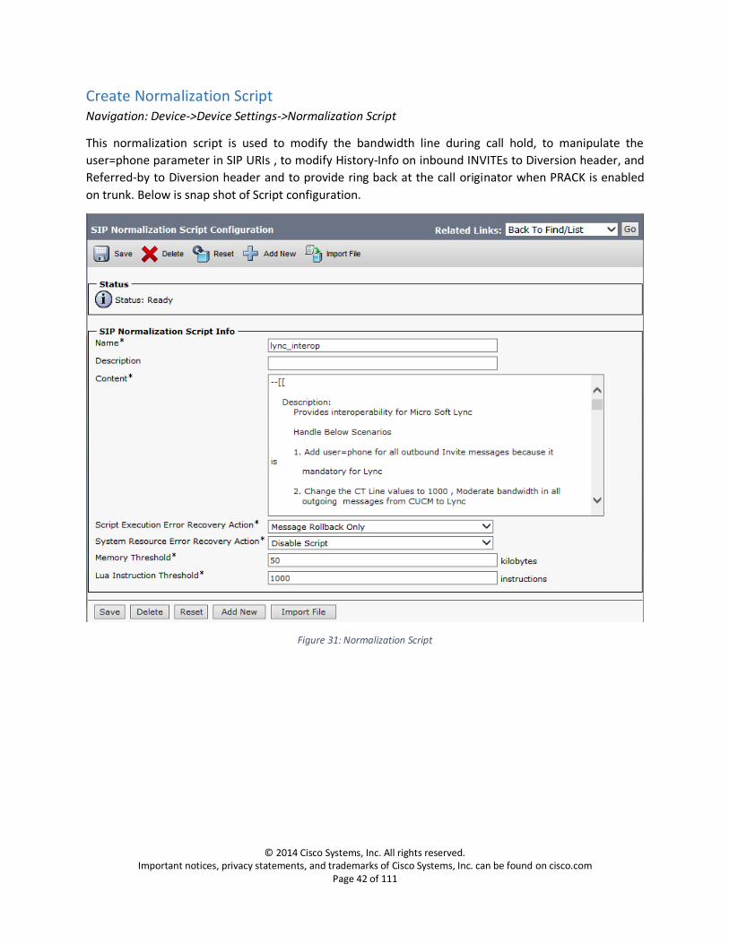
Create Normalization Script Navigation: Device->Device Settings->Normalization Script
This normalization script is used to modify the bandwidth line during call hold, to manipulate the
user=phone parameter in SIP URIs , to modify History-Info on inbound INVITEs to Diversion header, and
Referred-by to Diversion header and to provide ring back at the call originator when PRACK is enabled
on trunk. Below is snap shot of Script configuration.
Figure 31: Normalization Script
© 2014 Cisco Systems, Inc. All rights reserved. Important notices, privacy statements, and trademarks of Cisco Systems, Inc. can be found on cisco.com
Page 43 of 111
CISCO UCM Normalization Script
Download the script “SIP normalization script (version 1.2) for audio interoperability between Microsoft
Lync 2013 and Cisco Unified Communications Manager” (lync_interop_lua.zip) at Downloads Home >
Products > Unified Communications > Call Control > Cisco Unified Communications Manager
(CallManager) > Cisco Unified Communications Manager Version 10.0 > SIP Normalization and
Transparency Scripts-Scripts:
http://software.cisco.com/download/release.html?i=!y&mdfid=284603137&softwareid=284695022&release
=Scripts&os=
Translation Pattern Navigation: Call Routing-> Translation Pattern Configuration
1. Set Translation Pattern: Enter the ten digit number pattern to be translated 2. Set Called Party Transform Mask: Enter the four digit number pattern to be translated to, these
will be the Cisco Phone extension pattern.

© 2014 Cisco Systems, Inc. All rights reserved. Important notices, privacy statements, and trademarks of Cisco Systems, Inc. can be found on cisco.com
Page 44 of 111
Figure 32: Translation Pattern
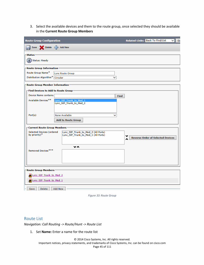
Route Group Navigation: Call Routing -> Route/Hunt -> Route Group
1. Set Route Group Name: Enter a name for the route group
2. Set Distribution Algorithm: Select the preferred distribution algorithm from the available list
© 2014 Cisco Systems, Inc. All rights reserved. Important notices, privacy statements, and trademarks of Cisco Systems, Inc. can be found on cisco.com
Page 45 of 111
3. Select the available devices and them to the route group, once selected they should be available
in the Current Route Group Members
Figure 33: Route Group
Route List Navigation: Call Routing -> Route/Hunt -> Route List
1. Set Name: Enter a name for the route list
© 2014 Cisco Systems, Inc. All rights reserved. Important notices, privacy statements, and trademarks of Cisco Systems, Inc. can be found on cisco.com
Page 46 of 111
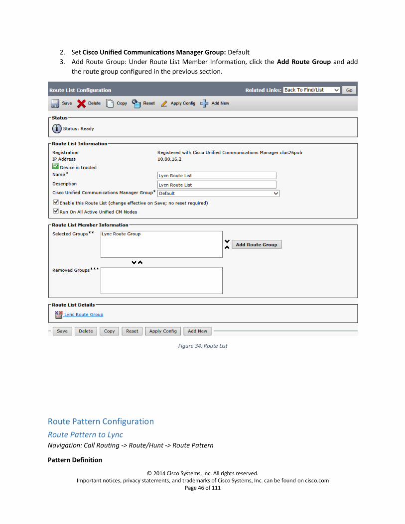
2. Set Cisco Unified Communications Manager Group: Default
3. Add Route Group: Under Route List Member Information, click the Add Route Group and add
the route group configured in the previous section.
Figure 34: Route List
Route Pattern Configuration
Route Pattern to Lync Navigation: Call Routing -> Route/Hunt -> Route Pattern
Pattern Definition

© 2014 Cisco Systems, Inc. All rights reserved. Important notices, privacy statements, and trademarks of Cisco Systems, Inc. can be found on cisco.com
Page 47 of 111
1. Set Route Pattern: Enter the routing pattern 2. Set Gateway/Route List: Select the Route List you have created under Call Routing ->
Route/Hunt -> Route List
Calling Party Transformations 3. Set Prefix Digits (Outgoing Calls): +1
Called Party Transformations 4. Set Prefix Digits(Outgoing Calls): +1

© 2014 Cisco Systems, Inc. All rights reserved. Important notices, privacy statements, and trademarks of Cisco Systems, Inc. can be found on cisco.com
Page 48 of 111
Figure 35: Route Pattern -1
© 2014 Cisco Systems, Inc. All rights reserved. Important notices, privacy statements, and trademarks of Cisco Systems, Inc. can be found on cisco.com
Page 49 of 111
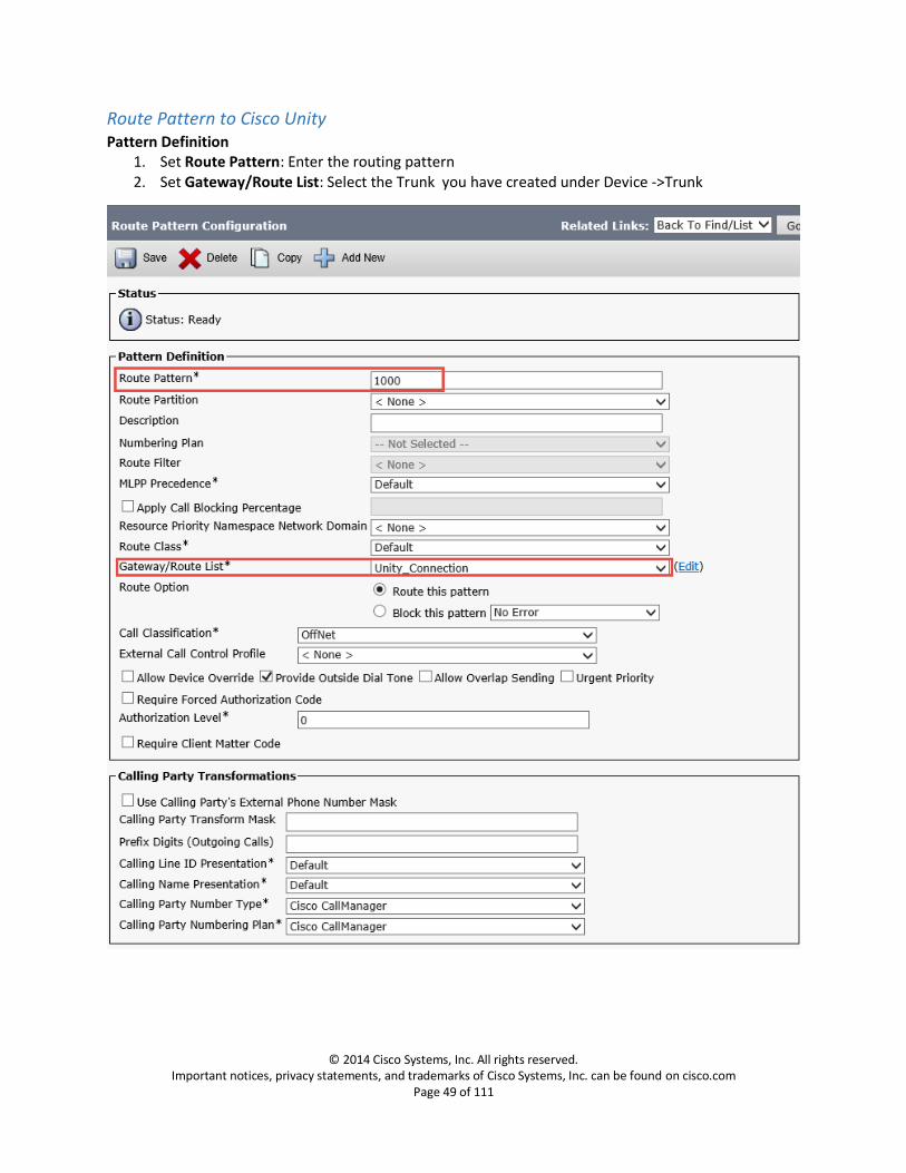
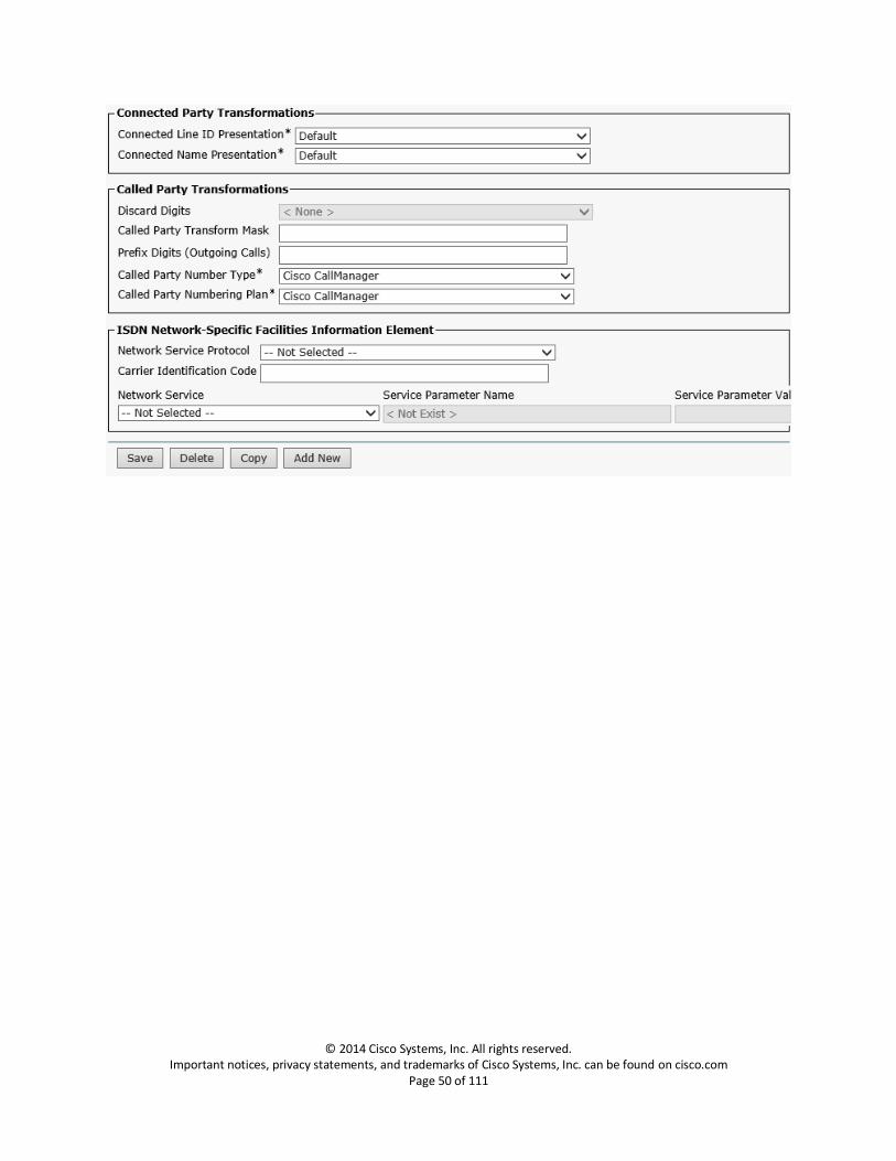
Route Pattern to Cisco Unity Pattern Definition
1. Set Route Pattern: Enter the routing pattern 2. Set Gateway/Route List: Select the Trunk you have created under Device ->Trunk
© 2014 Cisco Systems, Inc. All rights reserved. Important notices, privacy statements, and trademarks of Cisco Systems, Inc. can be found on cisco.com
Page 50 of 111

© 2014 Cisco Systems, Inc. All rights reserved. Important notices, privacy statements, and trademarks of Cisco Systems, Inc. can be found on cisco.com
Page 51 of 111
Route Pattern to Gateway Navigation: Call Routing -> Route/Hunt -> Route Pattern
1. Set Route Pattern: \+1XXXXXXXXXX
2. Set Gateway/Route List: Select the End-Point you have created in the gateway configuration
under Device -> Gateway
3. Set Called Party Transform Mask: XXXXXXXXXX

© 2014 Cisco Systems, Inc. All rights reserved. Important notices, privacy statements, and trademarks of Cisco Systems, Inc. can be found on cisco.com
Page 52 of 111
Figure 36: Route Pattern to Gateway
© 2014 Cisco Systems, Inc. All rights reserved. Important notices, privacy statements, and trademarks of Cisco Systems, Inc. can be found on cisco.com
Page 53 of 111
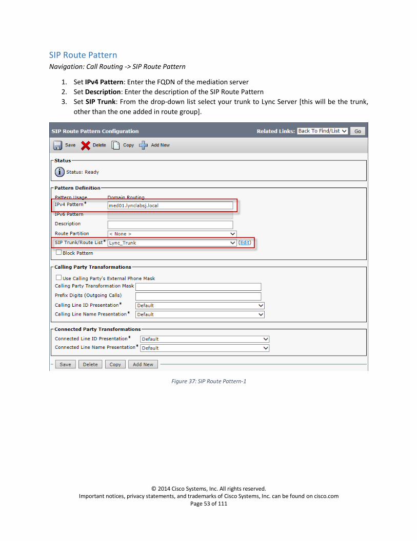
SIP Route Pattern Navigation: Call Routing -> SIP Route Pattern
1. Set IPv4 Pattern: Enter the FQDN of the mediation server
2. Set Description: Enter the description of the SIP Route Pattern
3. Set SIP Trunk: From the drop-down list select your trunk to Lync Server [this will be the trunk,
other than the one added in route group].
Figure 37: SIP Route Pattern-1
© 2014 Cisco Systems, Inc. All rights reserved. Important notices, privacy statements, and trademarks of Cisco Systems, Inc. can be found on cisco.com
Page 54 of 111
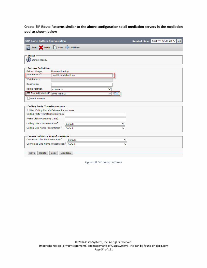
Create SIP Route Patterns similar to the above configuration to all mediation servers in the mediation
pool as shown below
Figure 38: SIP Route Pattern-2
© 2014 Cisco Systems, Inc. All rights reserved. Important notices, privacy statements, and trademarks of Cisco Systems, Inc. can be found on cisco.com
Page 55 of 111
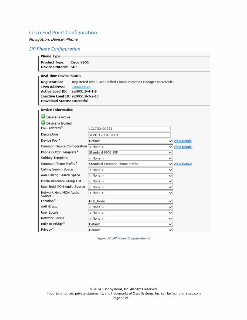
Cisco End Point Configuration Navigation: Device->Phone
SIP Phone Configuration
Figure 39: SIP Phone Configuration-1

© 2014 Cisco Systems, Inc. All rights reserved. Important notices, privacy statements, and trademarks of Cisco Systems, Inc. can be found on cisco.com
Page 56 of 111
Figure 40: SIP Phone Configuration-2
© 2014 Cisco Systems, Inc. All rights reserved. Important notices, privacy statements, and trademarks of Cisco Systems, Inc. can be found on cisco.com
Page 57 of 111
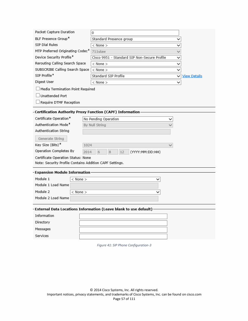
Figure 41: SIP Phone Configuration-3

© 2014 Cisco Systems, Inc. All rights reserved. Important notices, privacy statements, and trademarks of Cisco Systems, Inc. can be found on cisco.com
Page 58 of 111
Figure 42: SIP Phone Configuration-4
© 2014 Cisco Systems, Inc. All rights reserved. Important notices, privacy statements, and trademarks of Cisco Systems, Inc. can be found on cisco.com
Page 59 of 111
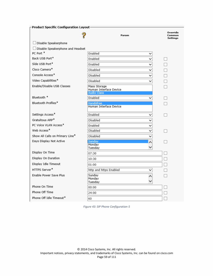
Figure 43: SIP Phone Configuration-5

© 2014 Cisco Systems, Inc. All rights reserved. Important notices, privacy statements, and trademarks of Cisco Systems, Inc. can be found on cisco.com
Page 60 of 111
Figure 44: SIP Phone Configuration-6
© 2014 Cisco Systems, Inc. All rights reserved. Important notices, privacy statements, and trademarks of Cisco Systems, Inc. can be found on cisco.com
Page 61 of 111
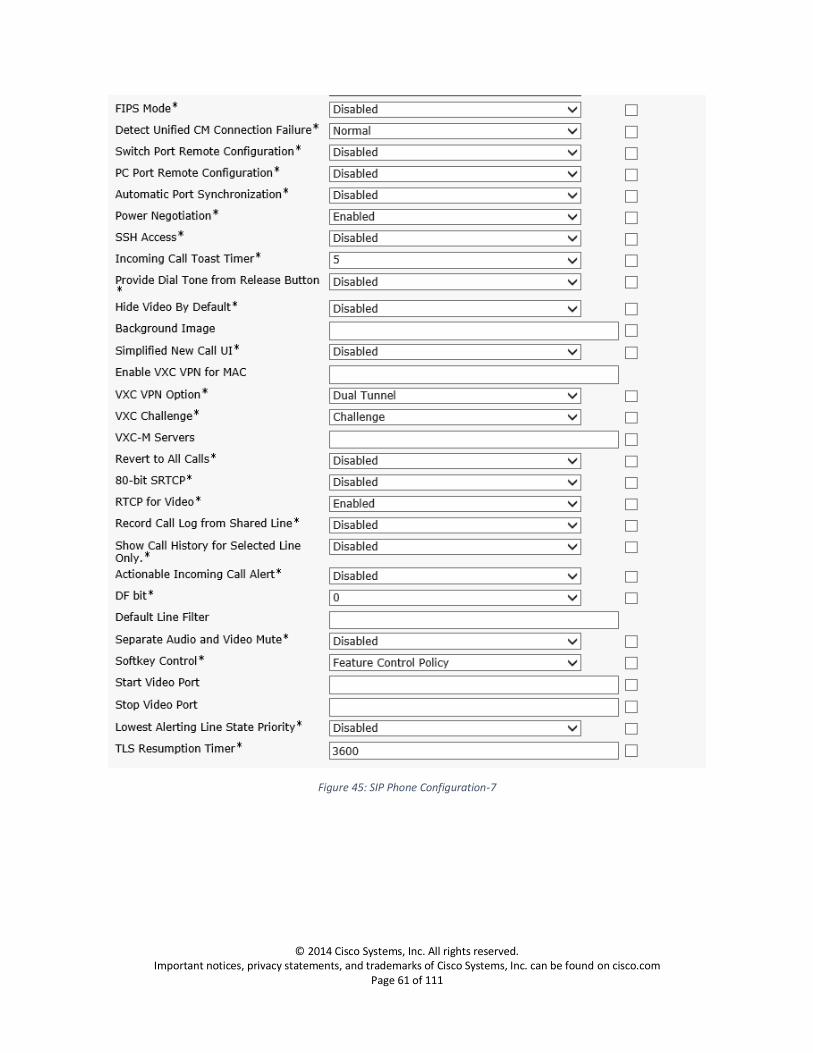
Figure 45: SIP Phone Configuration-7

© 2014 Cisco Systems, Inc. All rights reserved. Important notices, privacy statements, and trademarks of Cisco Systems, Inc. can be found on cisco.com
Page 62 of 111
Figure 46: SIP Phone Configuration-8

© 2014 Cisco Systems, Inc. All rights reserved. Important notices, privacy statements, and trademarks of Cisco Systems, Inc. can be found on cisco.com
Page 63 of 111
Figure 47: SIP Phone Configuration-9

© 2014 Cisco Systems, Inc. All rights reserved. Important notices, privacy statements, and trademarks of Cisco Systems, Inc. can be found on cisco.com
Page 64 of 111
Figure 48: SIP Phone Configuration-10
© 2014 Cisco Systems, Inc. All rights reserved. Important notices, privacy statements, and trademarks of Cisco Systems, Inc. can be found on cisco.com
Page 65 of 111
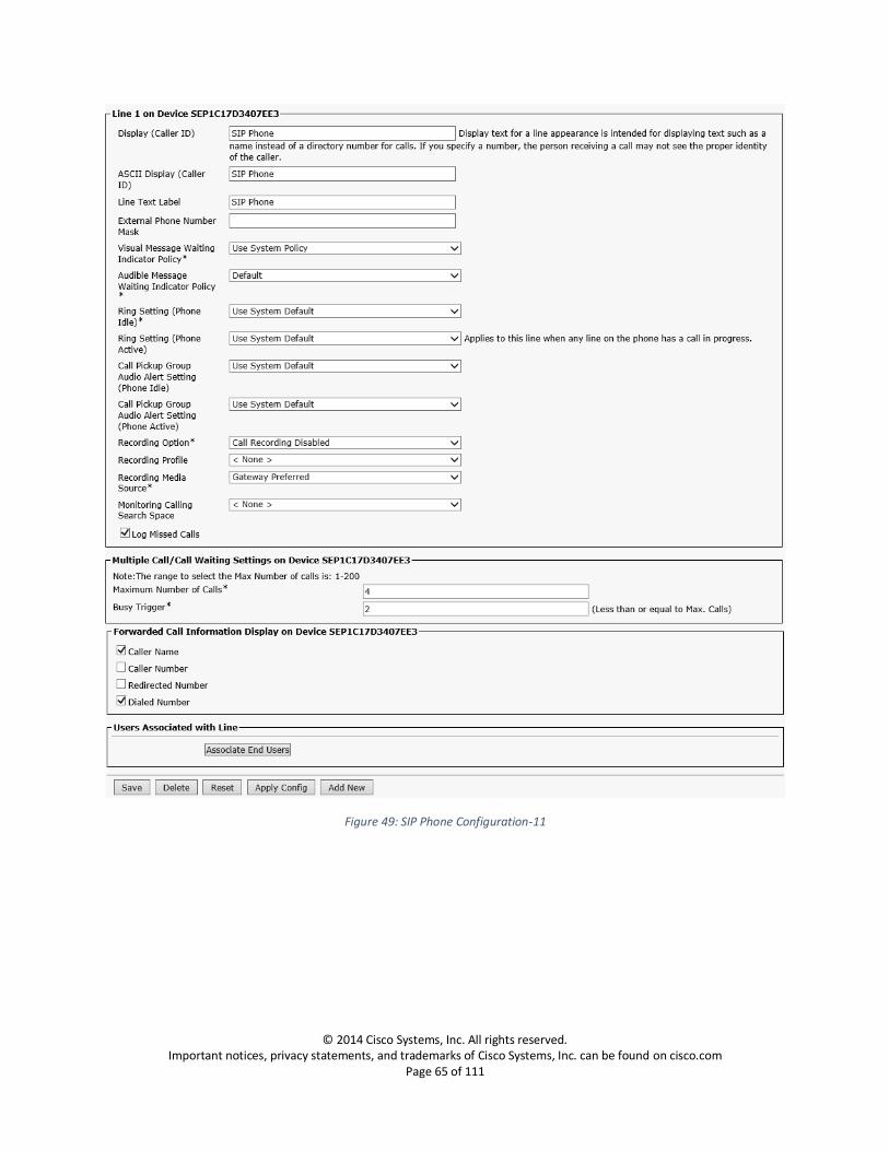
Figure 49: SIP Phone Configuration-11
© 2014 Cisco Systems, Inc. All rights reserved. Important notices, privacy statements, and trademarks of Cisco Systems, Inc. can be found on cisco.com
Page 66 of 111
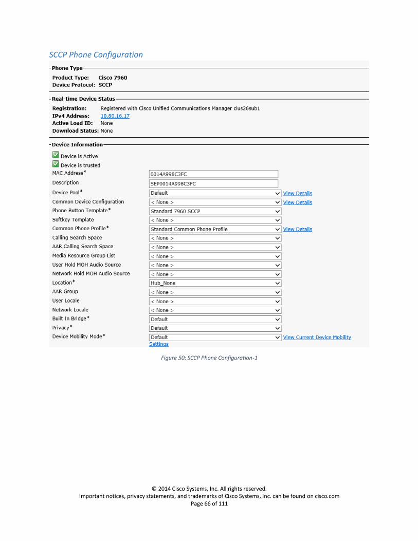
SCCP Phone Configuration
Figure 50: SCCP Phone Configuration-1

© 2014 Cisco Systems, Inc. All rights reserved. Important notices, privacy statements, and trademarks of Cisco Systems, Inc. can be found on cisco.com
Page 67 of 111
Figure 51: SCCP Phone Configuration-2

© 2014 Cisco Systems, Inc. All rights reserved. Important notices, privacy statements, and trademarks of Cisco Systems, Inc. can be found on cisco.com
Page 68 of 111
Figure 52: SCCP Phone Configuration-3

© 2014 Cisco Systems, Inc. All rights reserved. Important notices, privacy statements, and trademarks of Cisco Systems, Inc. can be found on cisco.com
Page 69 of 111
Figure 53: SCCP Phone Configuration-4

© 2014 Cisco Systems, Inc. All rights reserved. Important notices, privacy statements, and trademarks of Cisco Systems, Inc. can be found on cisco.com
Page 70 of 111
Figure 54: SCCP Phone Configuration-7
© 2014 Cisco Systems, Inc. All rights reserved. Important notices, privacy statements, and trademarks of Cisco Systems, Inc. can be found on cisco.com
Page 71 of 111
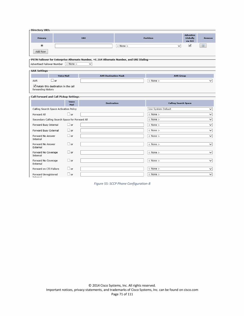
Figure 55: SCCP Phone Configuration-8
© 2014 Cisco Systems, Inc. All rights reserved. Important notices, privacy statements, and trademarks of Cisco Systems, Inc. can be found on cisco.com
Page 72 of 111
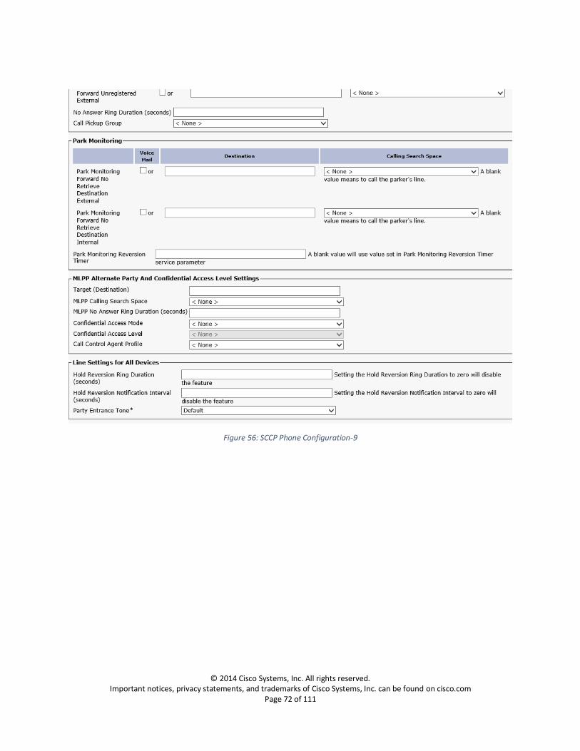
Figure 56: SCCP Phone Configuration-9

© 2014 Cisco Systems, Inc. All rights reserved. Important notices, privacy statements, and trademarks of Cisco Systems, Inc. can be found on cisco.com
Page 73 of 111
Figure 57: SCCP Phone Configuration-10

© 2014 Cisco Systems, Inc. All rights reserved. Important notices, privacy statements, and trademarks of Cisco Systems, Inc. can be found on cisco.com
Page 74 of 111
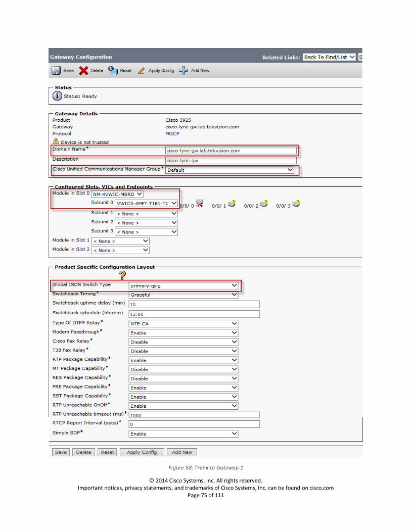
MGCP Gateway Configuration Navigation: Device -> Gateway
1. Set Gateway Type: Select the gateway model you are using, from the available list of devices.
2. Set Domain Name: Enter the FQDN of the gateway device.
3. Set Cisco Unified Communications Manager Group: Default
4. Set Module in Slot 0: Select ‘NM-4VWIC-MBRD’
Upon saving the configuration, ‘Subunit’ configuration fields will appear a. Set Subunit 0: Select the model of T1 card (hardware), which is on your gateway.
5. Set Global ISDN Switch Type: primary-qsig
© 2014 Cisco Systems, Inc. All rights reserved. Important notices, privacy statements, and trademarks of Cisco Systems, Inc. can be found on cisco.com
Page 75 of 111
Figure 58: Trunk to Gateway-1

© 2014 Cisco Systems, Inc. All rights reserved. Important notices, privacy statements, and trademarks of Cisco Systems, Inc. can be found on cisco.com
Page 76 of 111
After saving the configuration page, beside the subunit (subunit 0 here) you have configured, click on
the interface to which you have plugged the cable. A new configuration page appears, proceed with the
configuration steps described below.
6. Set Device Pool: Default
7. Confirm send Extra Leading Character in Display IE***: is unchecked
Figure 59: Trunk to Gateway-2

© 2014 Cisco Systems, Inc. All rights reserved. Important notices, privacy statements, and trademarks of Cisco Systems, Inc. can be found on cisco.com
Page 77 of 111
Figure 60: Trunk to Gateway-3

© 2014 Cisco Systems, Inc. All rights reserved. Important notices, privacy statements, and trademarks of Cisco Systems, Inc. can be found on cisco.com
Page 78 of 111
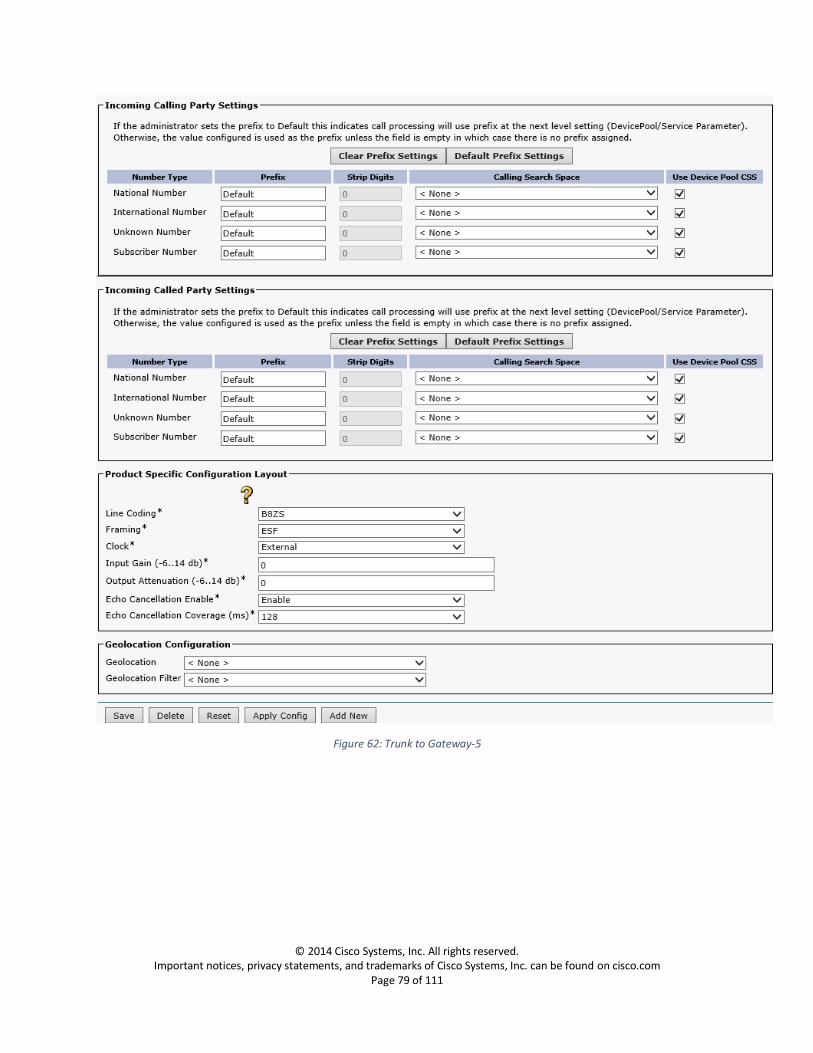
Figure 61: Trunk to Gateway-4
© 2014 Cisco Systems, Inc. All rights reserved. Important notices, privacy statements, and trademarks of Cisco Systems, Inc. can be found on cisco.com
Page 79 of 111
Figure 62: Trunk to Gateway-5
© 2014 Cisco Systems, Inc. All rights reserved. Important notices, privacy statements, and trademarks of Cisco Systems, Inc. can be found on cisco.com
Page 80 of 111
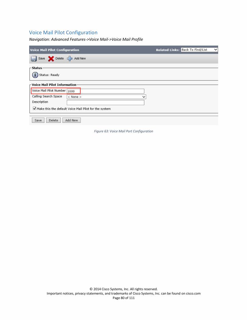
Voice Mail Pilot Configuration Navigation: Advanced Features->Voice Mail->Voice Mail Profile
Figure 63: Voice Mail Port Configuration

© 2014 Cisco Systems, Inc. All rights reserved. Important notices, privacy statements, and trademarks of Cisco Systems, Inc. can be found on cisco.com
Page 81 of 111
Cisco Unity Voice Mail Server Configuration
Phone System Configuration Navigation: Telephony Integrations -> Phone System
1. Set Phone System Name: Enter a name for the phone system 2. To navigate to the next step of configuration, move to related links ‘Add Port Group’ and click
Go.
Figure 64: Unity Phone System Configuration
© 2014 Cisco Systems, Inc. All rights reserved. Important notices, privacy statements, and trademarks of Cisco Systems, Inc. can be found on cisco.com
Page 82 of 111
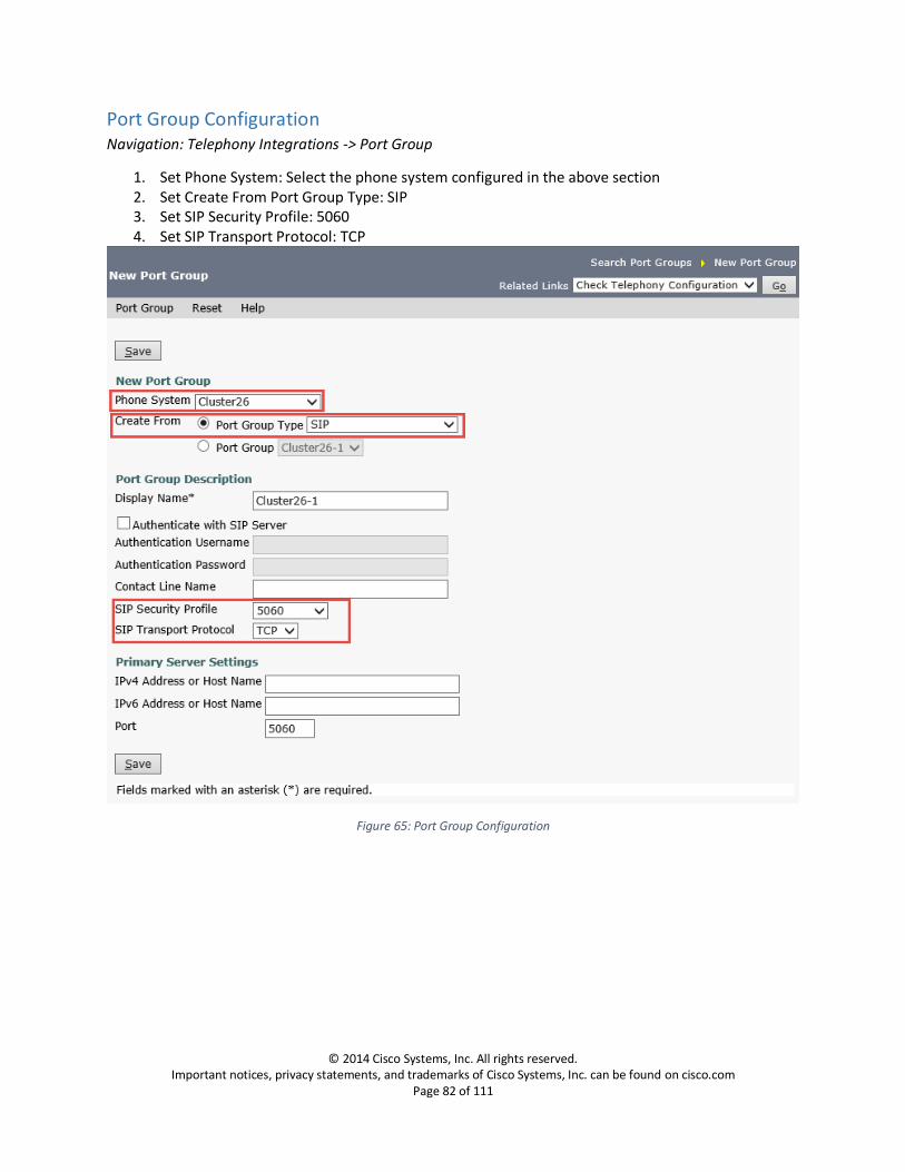
Port Group Configuration Navigation: Telephony Integrations -> Port Group
1. Set Phone System: Select the phone system configured in the above section 2. Set Create From Port Group Type: SIP 3. Set SIP Security Profile: 5060 4. Set SIP Transport Protocol: TCP
Figure 65: Port Group Configuration

© 2014 Cisco Systems, Inc. All rights reserved. Important notices, privacy statements, and trademarks of Cisco Systems, Inc. can be found on cisco.com
Page 83 of 111
Port Configuration Navigation: Telephony Integrations -> Port
1. Set Port Name: Enter Name for the port 2. Set Phone System: Select the phone system which you are creating the ports to 3. Set Port Group: Select the port group configured to the phone system selected in the above step 4. Set Server: Select the unity server
Figure 66: Port Configuration
© 2014 Cisco Systems, Inc. All rights reserved. Important notices, privacy statements, and trademarks of Cisco Systems, Inc. can be found on cisco.com
Page 84 of 111
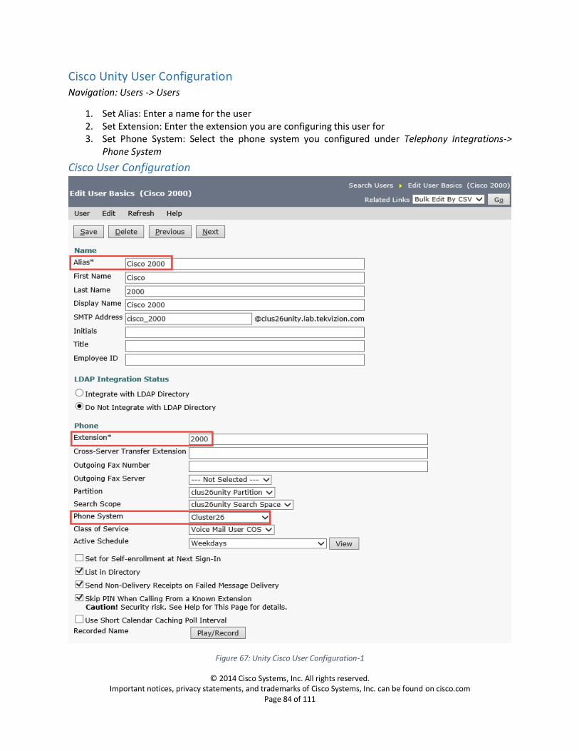
Cisco Unity User Configuration Navigation: Users -> Users
1. Set Alias: Enter a name for the user 2. Set Extension: Enter the extension you are configuring this user for 3. Set Phone System: Select the phone system you configured under Telephony Integrations->
Phone System
Cisco User Configuration
Figure 67: Unity Cisco User Configuration-1
© 2014 Cisco Systems, Inc. All rights reserved. Important notices, privacy statements, and trademarks of Cisco Systems, Inc. can be found on cisco.com
Page 85 of 111
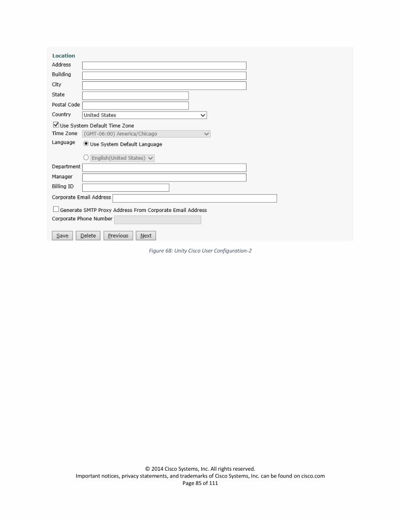
Figure 68: Unity Cisco User Configuration-2
© 2014 Cisco Systems, Inc. All rights reserved. Important notices, privacy statements, and trademarks of Cisco Systems, Inc. can be found on cisco.com
Page 86 of 111
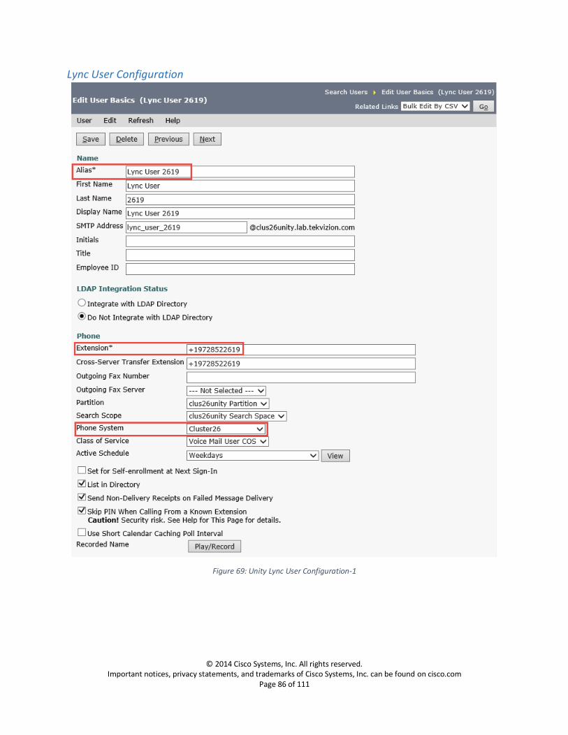
Lync User Configuration
Figure 69: Unity Lync User Configuration-1
© 2014 Cisco Systems, Inc. All rights reserved. Important notices, privacy statements, and trademarks of Cisco Systems, Inc. can be found on cisco.com
Page 87 of 111
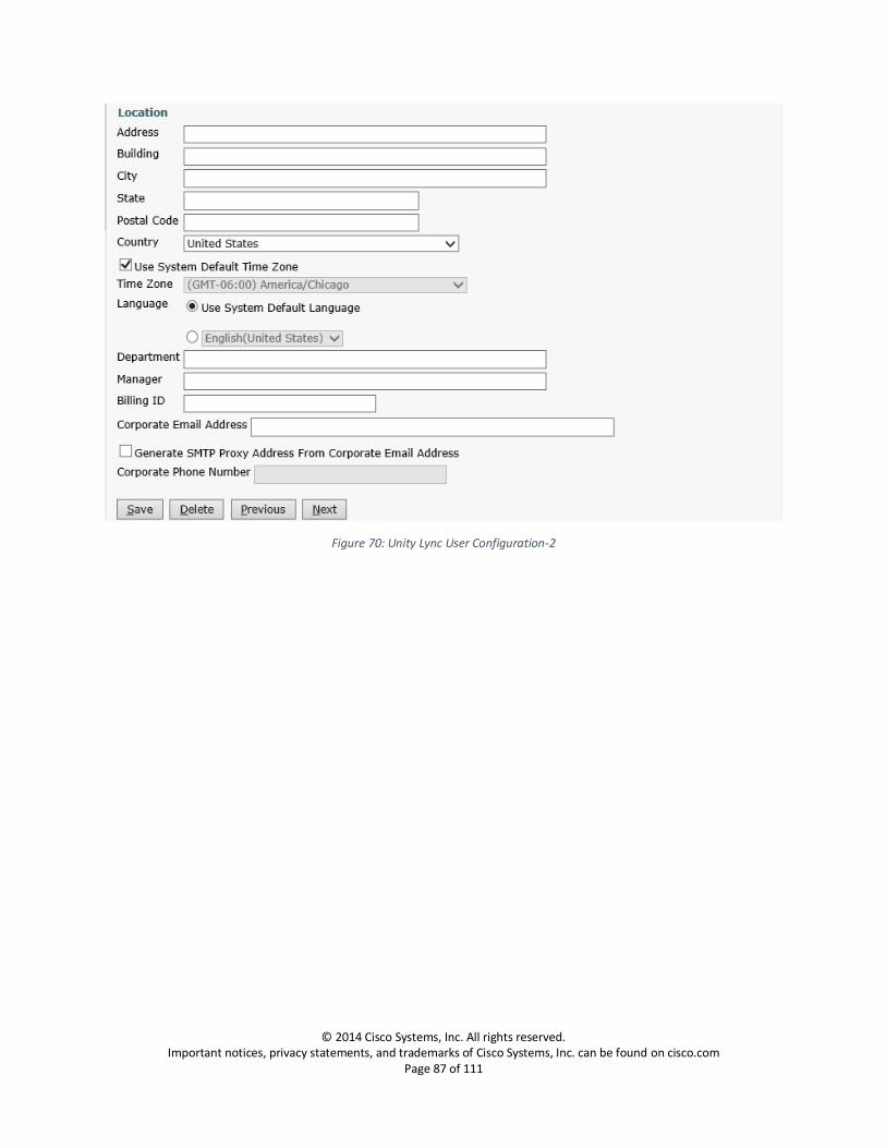
Figure 70: Unity Lync User Configuration-2
© 2014 Cisco Systems, Inc. All rights reserved. Important notices, privacy statements, and trademarks of Cisco Systems, Inc. can be found on cisco.com
Page 88 of 111
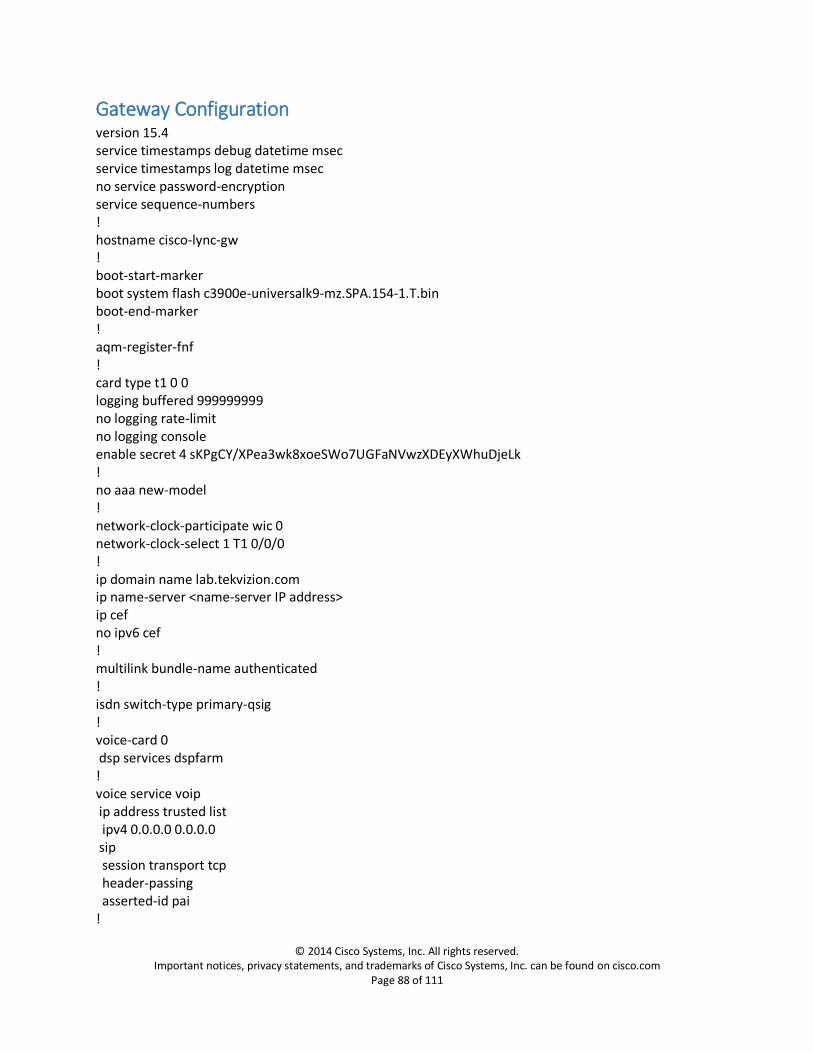
Gateway Configuration version 15.4 service timestamps debug datetime msec service timestamps log datetime msec no service password-encryption service sequence-numbers ! hostname cisco-lync-gw ! boot-start-marker boot system flash c3900e-universalk9-mz.SPA.154-1.T.bin boot-end-marker ! aqm-register-fnf ! card type t1 0 0 logging buffered 999999999 no logging rate-limit no logging console enable secret 4 sKPgCY/XPea3wk8xoeSWo7UGFaNVwzXDEyXWhuDjeLk ! no aaa new-model ! network-clock-participate wic 0 network-clock-select 1 T1 0/0/0 ! ip domain name lab.tekvizion.com ip name-server <name-server IP address> ip cef no ipv6 cef ! multilink bundle-name authenticated ! isdn switch-type primary-qsig ! voice-card 0 dsp services dspfarm ! voice service voip ip address trusted list ipv4 0.0.0.0 0.0.0.0 sip session transport tcp header-passing asserted-id pai !

© 2014 Cisco Systems, Inc. All rights reserved. Important notices, privacy statements, and trademarks of Cisco Systems, Inc. can be found on cisco.com
Page 89 of 111
voice class uri 1 sip host cisco-lync-gw.lab.tekvizion.com voice class codec 1 codec preference 1 g711ulaw codec preference 2 g711alaw ! controller T1 0/0/0 cablelength long 0db pri-group timeslots 1-24 service mgcp ! controller T1 0/0/1 cablelength long 0db ! controller T1 0/0/2 cablelength long 0db ! controller T1 0/0/3 cablelength long 0db ! interface GigabitEthernet0/0 description $ETH-LAN$$ETH-SW-LAUNCH$$INTF-INFO-GE 0/0$ ip address 10.64.3.69 255.255.0.0 duplex auto speed auto ! interface GigabitEthernet0/1 no ip address shutdown duplex auto speed auto ! interface GigabitEthernet0/2 no ip address shutdown duplex auto speed auto ! interface GigabitEthernet0/3 no ip address shutdown duplex auto speed auto ! interface Serial0/0/0:23 no ip address encapsulation hdlc isdn switch-type primary-qsig

© 2014 Cisco Systems, Inc. All rights reserved. Important notices, privacy statements, and trademarks of Cisco Systems, Inc. can be found on cisco.com
Page 90 of 111
isdn timer T310 120000 isdn protocol-emulate network isdn incoming-voice voice isdn bind-l3 ccm-manager no cdp enable ! ip default-gateway <default-gateway IP Address> ip forward-protocol nd ! ip http server ip http access-class 23 ip http authentication local ip http secure-server ip http timeout-policy idle 60 life 86400 requests 10000 ! ip route 0.0.0.0 0.0.0.0 10.64.1.1 ! nls resp-timeout 1 cpd cr-id 1 ! control-plane ! voice-port 0/0/0:23 ! voice-port 0/1/0 ! voice-port 0/1/1 ! voice-port 0/1/2 ! voice-port 0/1/3 ! mgcp mgcp call-agent clus26sub1 service-type mgcp version 0.1 mgcp dtmf-relay voip codec all mode nte-ca mgcp rtp unreachable timeout 1000 action notify mgcp modem passthrough voip mode nse mgcp voice-quality-stats mgcp package-capability rtp-package mgcp package-capability sst-package mgcp package-capability pre-package mgcp package-capability fm-package no mgcp package-capability res-package no mgcp package-capability fxr-package no mgcp timer receive-rtcp mgcp sdp simple mgcp fax t38 ecm
© 2014 Cisco Systems, Inc. All rights reserved. Important notices, privacy statements, and trademarks of Cisco Systems, Inc. can be found on cisco.com
Page 91 of 111
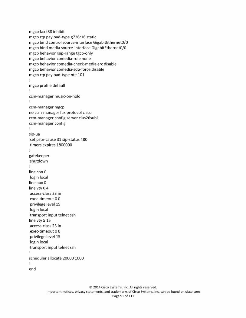
mgcp fax t38 inhibit mgcp rtp payload-type g726r16 static mgcp bind control source-interface GigabitEthernet0/0 mgcp bind media source-interface GigabitEthernet0/0 mgcp behavior rsip-range tgcp-only mgcp behavior comedia-role none mgcp behavior comedia-check-media-src disable mgcp behavior comedia-sdp-force disable mgcp rtp payload-type nte 101 ! mgcp profile default ! ccm-manager music-on-hold ! ccm-manager mgcp no ccm-manager fax protocol cisco ccm-manager config server clus26sub1 ccm-manager config ! sip-ua set pstn-cause 31 sip-status 480 timers expires 1800000 ! gatekeeper shutdown ! line con 0 login local line aux 0 line vty 0 4 access-class 23 in exec-timeout 0 0 privilege level 15 login local transport input telnet ssh line vty 5 15 access-class 23 in exec-timeout 0 0 privilege level 15 login local transport input telnet ssh ! scheduler allocate 20000 1000 ! end
© 2014 Cisco Systems, Inc. All rights reserved. Important notices, privacy statements, and trademarks of Cisco Systems, Inc. can be found on cisco.com
Page 92 of 111
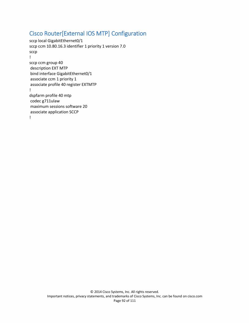
Cisco Router[External IOS MTP] Configuration sccp local GigabitEthernet0/1 sccp ccm 10.80.16.3 identifier 1 priority 1 version 7.0 sccp ! sccp ccm group 40 description EXT MTP bind interface GigabitEthernet0/1 associate ccm 1 priority 1 associate profile 40 register EXTMTP ! dspfarm profile 40 mtp codec g711ulaw maximum sessions software 20 associate application SCCP !
© 2014 Cisco Systems, Inc. All rights reserved. Important notices, privacy statements, and trademarks of Cisco Systems, Inc. can be found on cisco.com
Page 93 of 111
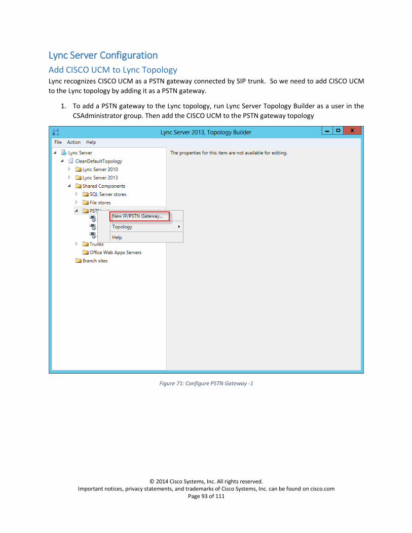
Lync Server Configuration
Add CISCO UCM to Lync Topology Lync recognizes CISCO UCM as a PSTN gateway connected by SIP trunk. So we need to add CISCO UCM
to the Lync topology by adding it as a PSTN gateway.
1. To add a PSTN gateway to the Lync topology, run Lync Server Topology Builder as a user in the
CSAdministrator group. Then add the CISCO UCM to the PSTN gateway topology
Figure 71: Configure PSTN Gateway -1

© 2014 Cisco Systems, Inc. All rights reserved. Important notices, privacy statements, and trademarks of Cisco Systems, Inc. can be found on cisco.com
Page 94 of 111
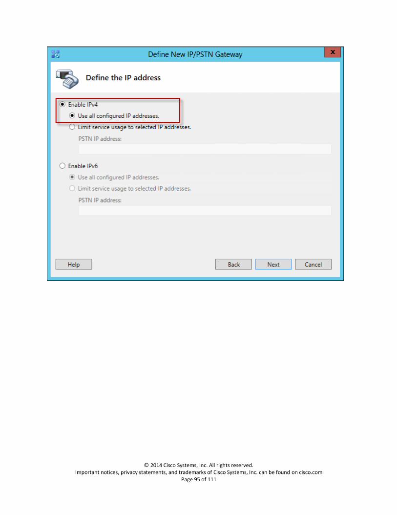
2. Set FQDN: This is the IP Address or FQDN of the CISCO UCM.
Figure 72: Configure PSTN Gateway -2
© 2014 Cisco Systems, Inc. All rights reserved. Important notices, privacy statements, and trademarks of Cisco Systems, Inc. can be found on cisco.com
Page 95 of 111

© 2014 Cisco Systems, Inc. All rights reserved. Important notices, privacy statements, and trademarks of Cisco Systems, Inc. can be found on cisco.com
Page 96 of 111
3. Set Trunk Name: This is the FQDN of the CISCO UCM
4. Set Listening port for IP/PSTN gateway: This Listening port should match the Incoming Port
setting in the CISCO UCM’s SIP Trunk Security Profile.
5. Set SIP Transport Protocol: TCP
6. Set Associate Mediation Server: Assign this PSTN gateway to the Mediation Server.
Medpool.lynclabkm2013.local is used here for example.
Figure 73: Configure PSTN Gateway -3

© 2014 Cisco Systems, Inc. All rights reserved. Important notices, privacy statements, and trademarks of Cisco Systems, Inc. can be found on cisco.com
Page 97 of 111
7. Publish topology to make the changes effective, refer to below scree capture for the process.
Figure 74: Publish Topology

© 2014 Cisco Systems, Inc. All rights reserved. Important notices, privacy statements, and trademarks of Cisco Systems, Inc. can be found on cisco.com
Page 98 of 111
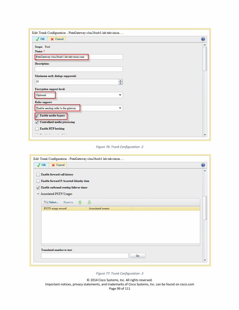
Trunk Configuration Navigation: Voice Routing -> Trunk Configuration
1. Create a Pool Trunk by selecting New
2. Select Service: Select the trunk to CISCO UCM you created in topology builder
3. Set Maximum early dialogs supported: 20
4. Set Encryption support level: Optional
5. Set Refer Support: Enable sending refer to the gateway
6. Confirm Enable media bypass: is checked
7. Confirm Centralized media processing: is checked
8. Confirm Enable RTP latching: is unchecked
9. Confirm Enable forward call history: is unchecked
10. Confirm Enable forward P-Asserted-Identity data: is unchecked
11. Confirm Enable outbound routing failover timer: is checked
Figure 75: Trunk Configuration -1
© 2014 Cisco Systems, Inc. All rights reserved. Important notices, privacy statements, and trademarks of Cisco Systems, Inc. can be found on cisco.com
Page 99 of 111
Figure 76: Trunk Configuration -2
Figure 77: Trunk Configuration -3
© 2014 Cisco Systems, Inc. All rights reserved. Important notices, privacy statements, and trademarks of Cisco Systems, Inc. can be found on cisco.com
Page 100 of 111
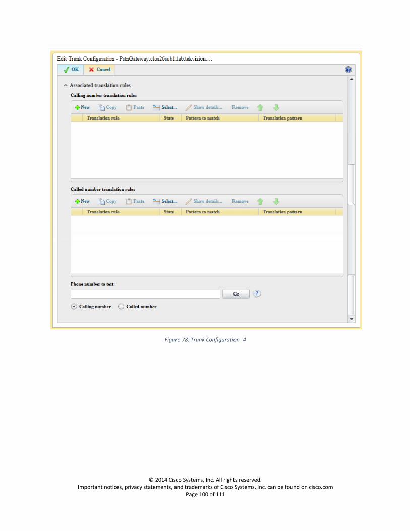
Figure 78: Trunk Configuration -4
© 2014 Cisco Systems, Inc. All rights reserved. Important notices, privacy statements, and trademarks of Cisco Systems, Inc. can be found on cisco.com
Page 101 of 111
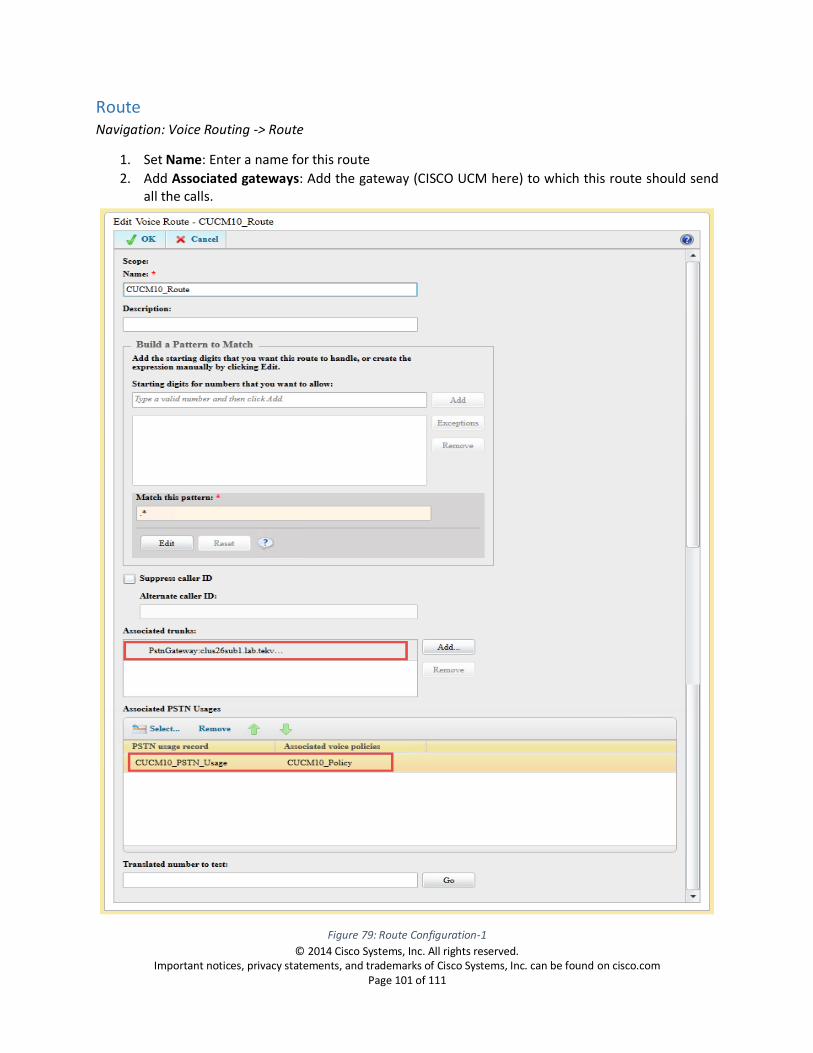
Route Navigation: Voice Routing -> Route
1. Set Name: Enter a name for this route
2. Add Associated gateways: Add the gateway (CISCO UCM here) to which this route should send all the calls.
Figure 79: Route Configuration-1
© 2014 Cisco Systems, Inc. All rights reserved. Important notices, privacy statements, and trademarks of Cisco Systems, Inc. can be found on cisco.com
Page 102 of 111
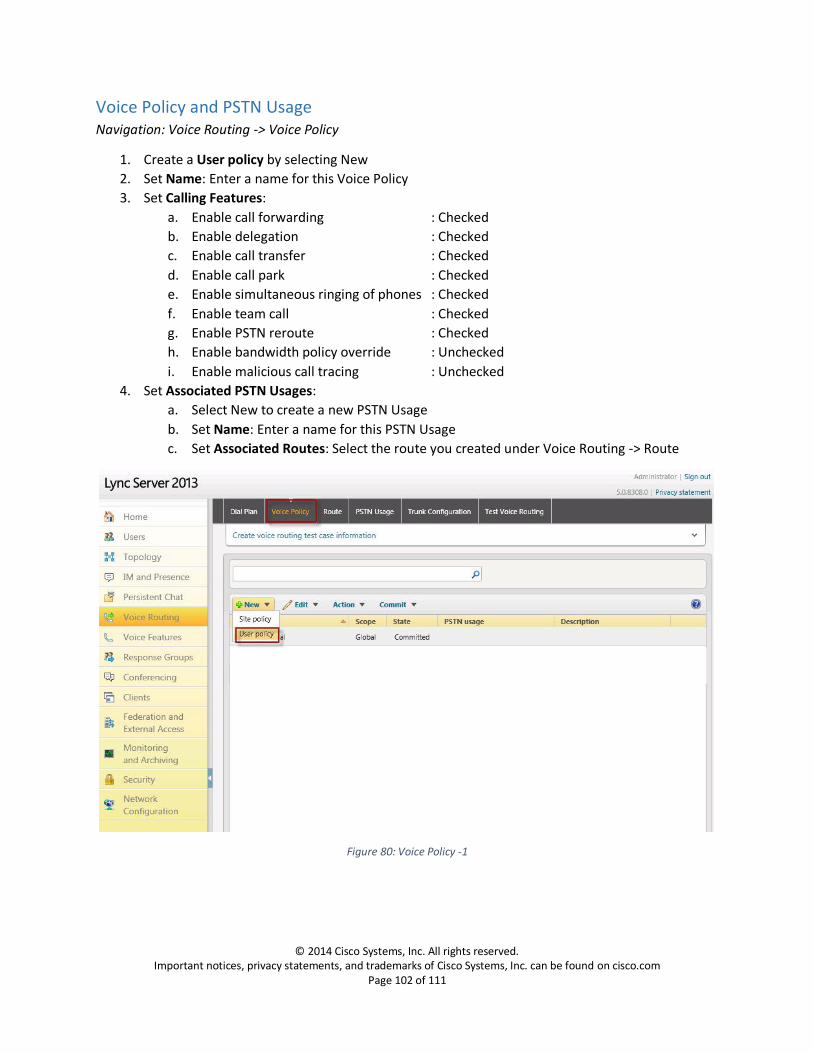
Voice Policy and PSTN Usage Navigation: Voice Routing -> Voice Policy
1. Create a User policy by selecting New
2. Set Name: Enter a name for this Voice Policy
3. Set Calling Features:
a. Enable call forwarding : Checked
b. Enable delegation : Checked
c. Enable call transfer : Checked
d. Enable call park : Checked
e. Enable simultaneous ringing of phones : Checked
f. Enable team call : Checked
g. Enable PSTN reroute : Checked
h. Enable bandwidth policy override : Unchecked
i. Enable malicious call tracing : Unchecked
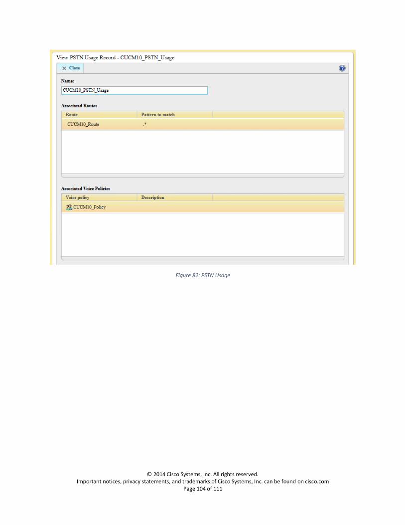
4. Set Associated PSTN Usages:
a. Select New to create a new PSTN Usage
b. Set Name: Enter a name for this PSTN Usage
c. Set Associated Routes: Select the route you created under Voice Routing -> Route
Figure 80: Voice Policy -1

© 2014 Cisco Systems, Inc. All rights reserved. Important notices, privacy statements, and trademarks of Cisco Systems, Inc. can be found on cisco.com
Page 103 of 111
Figure 81: Voice Policy -2
© 2014 Cisco Systems, Inc. All rights reserved. Important notices, privacy statements, and trademarks of Cisco Systems, Inc. can be found on cisco.com
Page 104 of 111
Figure 82: PSTN Usage
© 2014 Cisco Systems, Inc. All rights reserved. Important notices, privacy statements, and trademarks of Cisco Systems, Inc. can be found on cisco.com
Page 105 of 111
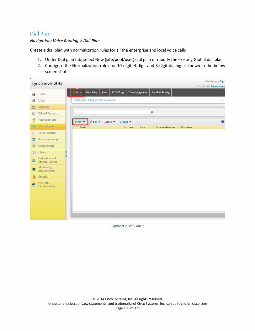
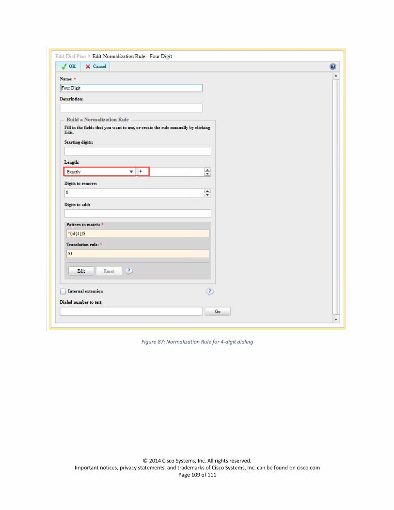
Dial Plan Navigation: Voice Routing-> Dial Plan
Create a dial plan with normalization rules for all the enterprise and local voice calls
1. Under Dial plan tab, select New (site/pool/user) dial plan or modify the existing Global dial plan
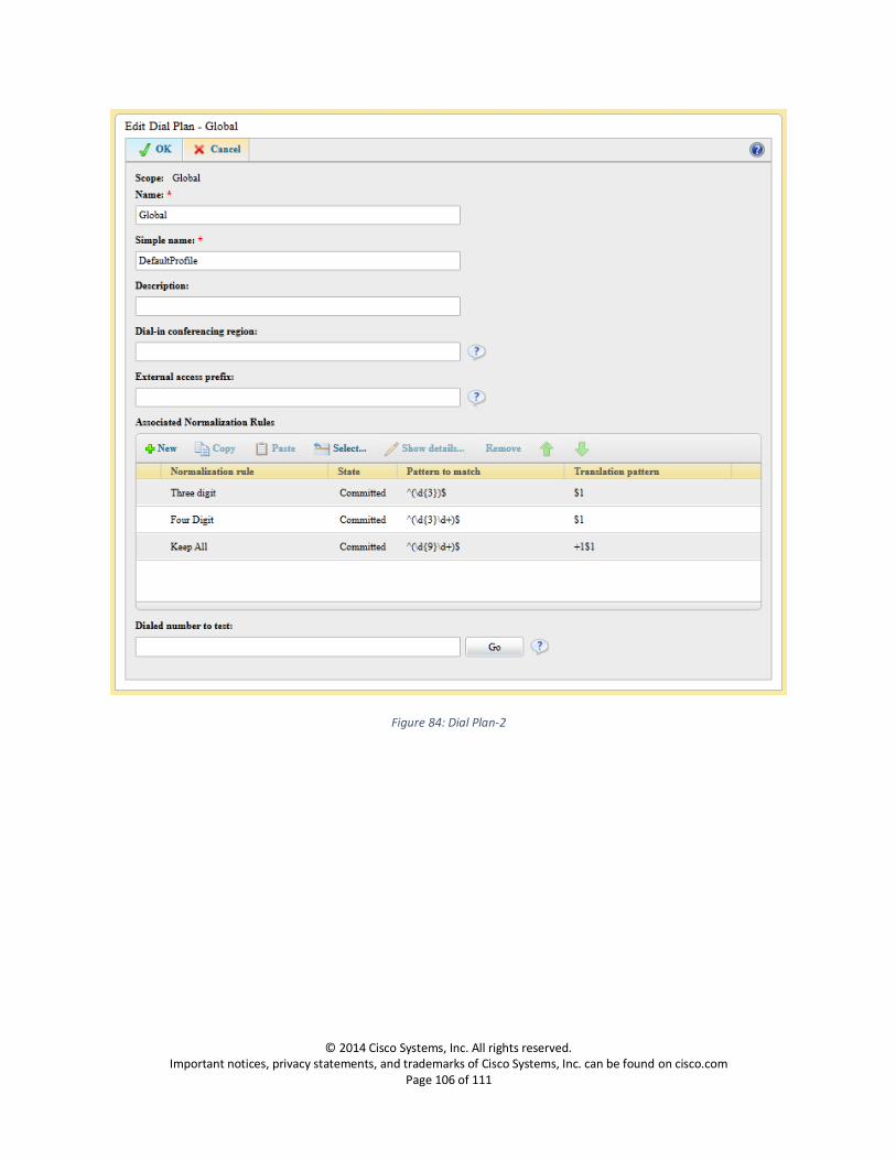
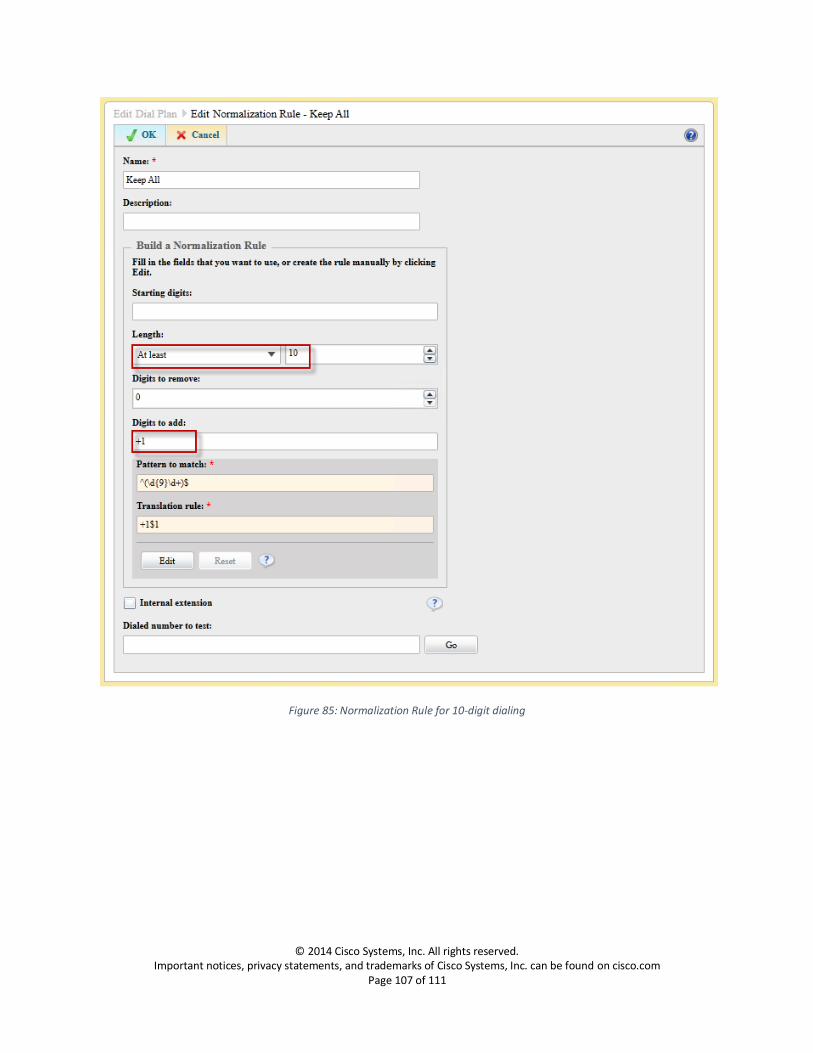
2. Configure the Normalization rules for 10-digit, 4-digit and 3-digit dialing as shown in the below
screen shots.
Figure 83: Dial Plan-1
© 2014 Cisco Systems, Inc. All rights reserved. Important notices, privacy statements, and trademarks of Cisco Systems, Inc. can be found on cisco.com
Page 106 of 111
Figure 84: Dial Plan-2
© 2014 Cisco Systems, Inc. All rights reserved. Important notices, privacy statements, and trademarks of Cisco Systems, Inc. can be found on cisco.com
Page 107 of 111
Figure 85: Normalization Rule for 10-digit dialing

© 2014 Cisco Systems, Inc. All rights reserved. Important notices, privacy statements, and trademarks of Cisco Systems, Inc. can be found on cisco.com
Page 108 of 111
Figure 86: Normalization Rule for 3-digit dialing
© 2014 Cisco Systems, Inc. All rights reserved. Important notices, privacy statements, and trademarks of Cisco Systems, Inc. can be found on cisco.com
Page 109 of 111
Figure 87: Normalization Rule for 4-digit dialing
© 2014 Cisco Systems, Inc. All rights reserved. Important notices, privacy statements, and trademarks of Cisco Systems, Inc. can be found on cisco.com
Page 110 of 111
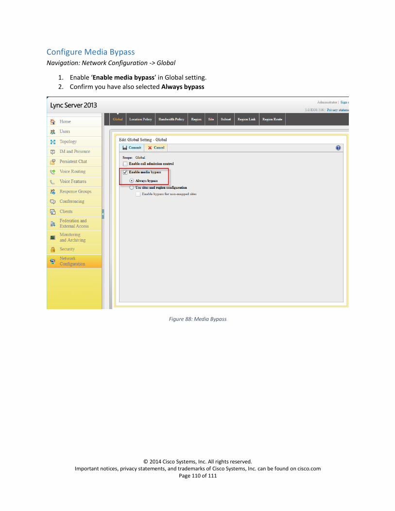
Configure Media Bypass Navigation: Network Configuration -> Global
1. Enable ‘Enable media bypass’ in Global setting.
2. Confirm you have also selected Always bypass
Figure 88: Media Bypass
© 2014 Cisco Systems, Inc. All rights reserved. Important notices, privacy statements, and trademarks of Cisco Systems, Inc. can be found on cisco.com
Page 111 of 111
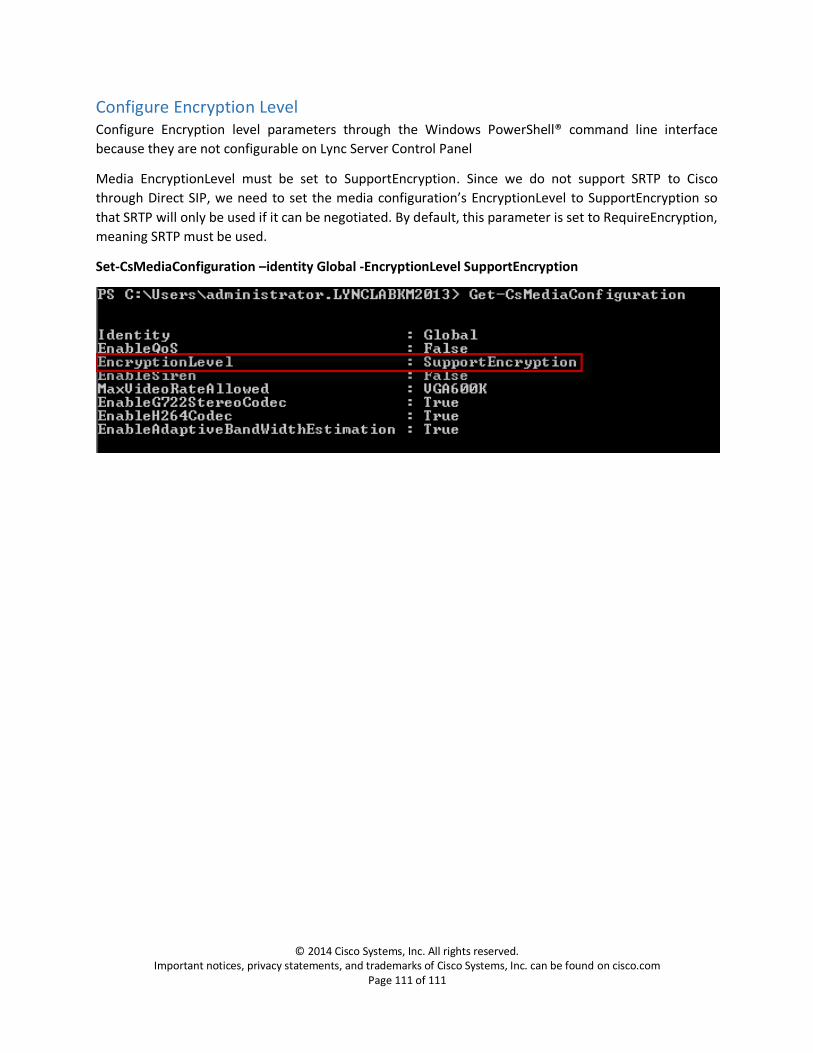
Configure Encryption Level Configure Encryption level parameters through the Windows PowerShell® command line interface
because they are not configurable on Lync Server Control Panel
Media EncryptionLevel must be set to SupportEncryption. Since we do not support SRTP to Cisco
through Direct SIP, we need to set the media configuration’s EncryptionLevel to SupportEncryption so
that SRTP will only be used if it can be negotiated. By default, this parameter is set to RequireEncryption,
meaning SRTP must be used.
Set-CsMediaConfiguration –identity Global -EncryptionLevel SupportEncryption