m-series enphase microinverteras-iberica.com/wp-content/uploads/download-manager-files/web/02... ·...
TRANSCRIPT
INSTALLATION AND OPERATION MANUAL
141-00024, Rev 02
M-Series Enphase Microinverter (M250 and M215)

Enphase Microinverter Installation and Operation
2015 Enphase Energy. All rights reserved. 141-00024 Rev 02
2
Corporate Headquarters Contact Information
Enphase Energy Inc. 1420 N. McDowell Blvd. Petaluma, CA 94954 USA http://www.enphase.com [email protected]
Other Information
Product information is subject to change without notice. All trademarks are recognised as the property of their respective owners. User documentation is updated frequently; Check the Enphase website (http://www.enphase.com/support) for the latest information. For warranty text refer to http://www.enphase.com/warranty. For Enphase patent information refer to http://enphase.com/company/patents/. © 2015 Enphase Energy Inc. All rights reserved.
Audience
This manual is intended for use by professional installation and maintenance personnel.

M-Series Microinverter Installation and Operation
2015 Enphase Energy. All rights reserved. 141-00024 Rev 02
3
Table of Contents Important Safety Information .......................................................................................................................................... 4
Read this First ................................................................................................................................................. 4 Product Labels ................................................................................................................................................. 4 Safety and Advisory Symbols .......................................................................................................................... 4 Safety Instructions ........................................................................................................................................... 4
General Safety .............................................................................................................................................................. 4 Microinverter Safety ...................................................................................................................................................... 5 Engage Cable and Accessory Safety ............................................................................................................................ 6
The Enphase Microinverter System ............................................................................................................................... 7 How the Microinverter Works ........................................................................................................................... 8
System Monitoring......................................................................................................................................................... 8 Optimal Reliability ......................................................................................................................................................... 8 Ease of Design .............................................................................................................................................................. 8
Planning for Microinverter Installation ............................................................................................................................ 9 Compatibility and Capacity .............................................................................................................................. 9
Compatibility ................................................................................................................................................................. 9 Branch Circuit Capacity ................................................................................................................................................. 9 Utility Service Requirements.......................................................................................................................................... 9
Lightning and Surge Suppression .................................................................................................................. 10 Parts and Tools Required .............................................................................................................................. 10
Enphase Equipment .................................................................................................................................................... 10 Other Items ................................................................................................................................................................. 10
Example Single-Phase Design ...................................................................................................................... 11 Enphase Items Needed for Example Design ............................................................................................................... 12 Non-Enphase Items Needed for Example Design ........................................................................................................ 12
Enphase Microinverter Installation ............................................................................................................................... 13 Step 1: Register the System .......................................................................................................................... 14 Step 2: Connect the Envoy Communications Gateway ................................................................................. 15 Step 3: Position the Enphase Engage™ Cable ............................................................................................. 16 Step 4: Install an AC Junction Box................................................................................................................. 17 Step 5: Attach the Microinverters to the Mounting Rail .................................................................................. 18 Step 6: Dress the Engage Cable ................................................................................................................... 19 Step 7: Connect the Microinverters................................................................................................................ 20 Step 8: Terminate the Unused End of the Engage Cable .............................................................................. 21 Step 9: Connect the Engage Cable to AC Junction Box ................................................................................ 22 Step 10: Complete the Installation Map ......................................................................................................... 23 Step 11: Connect the PV Modules ................................................................................................................. 23
Commissioning and Operation ..................................................................................................................................... 24 Energise the System ...................................................................................................................................... 24 Check the Envoy's progress .......................................................................................................................... 24 Configure the Grid Profile .............................................................................................................................. 25 Build the Virtual Array .................................................................................................................................... 25
Troubleshooting ........................................................................................................................................................... 26 Status LED Indications and Error Reporting .................................................................................................. 26
Start-up LED Operation ............................................................................................................................................... 26 Post-Start-up LED Indications ..................................................................................................................................... 26 Reported Faults ........................................................................................................................................................... 26
Troubleshoot an Inoperable Microinverter ..................................................................................................... 27 Disconnect a Microinverter ............................................................................................................................ 28 Install a Replacement Microinverter ............................................................................................................... 29
Engage Cable Planning and Ordering ......................................................................................................................... 30 Selecting Cable Type ..................................................................................................................................... 30 Connector Spacing Options ........................................................................................................................... 30 Voltage Type and Conductor Count Options ................................................................................................. 31 Cabling Length Options ................................................................................................................................. 31 Planning for Cable Lengths and Type ............................................................................................................ 31
Technical Data ............................................................................................................................................................. 33 Technical Considerations .............................................................................................................................. 33 Features and Specifications .......................................................................................................................... 33
M250 and M215 Features and Compliance ................................................................................................................. 33 M250-72 Specifications ............................................................................................................................................... 34 M250-60 Specifications ............................................................................................................................................... 35 M215-60-230-S25E and -S22E Specifications ............................................................................................................. 36 M215-60-230-S22 Specifications ................................................................................................................................. 37 Engage Cable Specifications ....................................................................................................................................... 38
Enphase Installation Map .............................................................................................................................. 39 Sample Schematic – 230 Vac, Single-Phase ................................................................................................ 40 Sample Schematic – 230 Vac, Three-Phase ................................................................................................. 41
Enphase Microinverter Installation and Operation
2015 Enphase Energy. All rights reserved. 141-00024 Rev 02
4
Important Safety Information
Read this First
This manual contains important instructions for use during installation and maintenance of the Enphase M215 and M250 Microinverters™.
Product Labels
The following symbols appear on the product label and are described here:
WARNING: Hot surface.
DANGER: Risk of electric shock.
Refer to product instructions.
Safety and Advisory Symbols
To reduce the risk of electric shock, and to ensure the safe installation and operation of the Enphase® Microinverter, the following safety symbols appear throughout this document to indicate dangerous conditions and important safety instructions.
DANGER! This indicates a hazardous situation, which if not avoided, will result in death or serious
injury.
WARNING! This indicates a situation where failure to follow instructions may be a safety hazard or
cause equipment malfunction. Use extreme caution and follow instructions carefully.
WARNING! This indicates a situation where failure to follow instructions may result in burn injury.
NOTE: This indicates information particularly important for optimal system operation. Follow instructions closely.
Safety Instructions
General Safety
CAUTION: Before installing or using the Enphase Microinverter, read all instructions and
cautionary markings in the technical description, on the Enphase Microinverter System, and on the photovoltaic (PV) equipment.
DANGER: Risk of electric shock. Do not use Enphase equipment in a manner not specified by the
manufacturer. Doing so may cause death or injury to persons, or damage to equipment.
DANGER: Risk of electric shock. Be aware that installation of this equipment includes risk of
electric shock. Do not install the AC junction box without first removing AC power from the Enphase System.
DANGER: Risk of electric shock. The DC conductors of this photovoltaic system are unearthed
and may be energised.
WARNING: Risk of electric shock. Always de-energise the AC branch circuit before servicing.
Never disconnect the DC connectors under load.
WARNING: Risk of electric shock. Risk of fire. Only use electrical system components approved
for wet locations.
WARNING: Risk of electric shock. Risk of fire. Only qualified personnel should troubleshoot,
install, or replace Enphase Microinverters or the Engage Cable and Accessories.
M-Series Microinverter Installation and Operation
2015 Enphase Energy. All rights reserved. 141-00024 Rev 02
5
WARNING: Risk of electric shock. Risk of fire. Ensure that all AC and DC wiring is correct and that
none of the AC or DC wires are pinched or damaged. Ensure that all AC junction boxes are properly closed.
WARNING: Risk of electric shock. Risk of fire. Do not exceed the maximum number of
microinverters in an AC branch circuit as listed in the manual. You must protect each microinverter AC branch circuit with a 20A maximum breaker.
WARNING: Do not connect Enphase Microinverters to the grid or energise the AC circuit(s) until
you have completed all of the installation procedures and have received prior approval from the electrical utility company.
NOTE: To ensure optimal reliability and to meet warranty requirements, the Enphase Microinverter
System must be installed according to the instructions in this manual.
NOTE: The AC and DC connectors on the cabling are rated as a disconnect only when used with
an Enphase Microinverter.
NOTE: Protection against lightning and resulting voltage surge must be in accordance with local
standards.
NOTE: Many PV modules have a central stiffening brace. In these cases, do not position the
connector and microinverter at the exact centre of the PV module. Instead, position the drop connectors so that the connectors do not conflict with the braces.
NOTE: Completely install all microinverters and all system AC connections prior to installing the
PV modules.
Microinverter Safety
WARNING: Risk of Skin Burn. The body of the Enphase Microinverter is the heat sink. Under
normal operating conditions, the temperature is 15°C above ambient, but under extreme conditions the microinverter can reach a temperature of 80°C. To reduce risk of burns, use caution when working with microinverters.
WARNING: Risk of electric shock. Risk of fire. If the AC cable on the microinverter is damaged, do not install the unit.
WARNING: Risk of electric shock. Risk of fire. Do not attempt to repair the Enphase Microinverter;
it contains no user-serviceable parts. If it fails, contact Enphase customer service to obtain an RMA (return merchandise authorization) number and start the replacement process. Tampering with or opening the Enphase Microinverter will void the warranty.
WARNING: Risk of Equipment Damage. You must match the DC operating voltage range of the
PV module with the allowable input voltage range of the Enphase Microinverter.
WARNING: Risk of Equipment Damage. The maximum open circuit voltage of the PV module
must not exceed the specified maximum input DC voltage of the Enphase Microinverter.
WARNING: Risk of Equipment Damage. The microinverter must be installed under the module,
out of rain and sun. Do not mount the microinverter in a position that allows long-term exposure to direct sunlight or in a vertical orientation that allows water to collect in the DC connector recess. Do not install the microinverter black side up or vertically, with the DC connectors facing up.
WARNING: Be aware that only qualified personnel may connect the Enphase Microinverter to the
utility grid.
NOTE: Some Enphase Microinverter models will not produce power until the Envoy
Communications Gateway is installed and configured with an appropriate grid profile. For instructions, refer to the Envoy Installation and Operation Manual at http://www.enphase.com.
NOTE: The Enphase Microinverter has field-adjustable voltage and frequency trip points that may
need to be set, depending upon local requirements. Only an authorised installer with the permission and following requirements of the local electrical authorities should make adjustments.
NOTE: The Enphase Microinverter works with single-phase or three-phase electrical service.
Enphase Microinverter Installation and Operation
2015 Enphase Energy. All rights reserved. 141-00024 Rev 02
6
Engage Cable and Accessory Safety
DANGER: Risk of electric shock. The Engage Cable terminator cap must not be installed while
power is connected.
WARNING: Risk of electric shock. Risk of fire. When stripping the sheath from the Engage Cable,
make sure the conductors are not damaged. If the exposed wires are damaged, the system may not function properly.
WARNING: Risk of electric shock. Risk of fire. Do not leave AC connectors on the Engage Cable
uncovered for an extended period. If you do not replace the microinverter immediately, you must cover any unused connector with a sealing cap. Sealing caps may not be reused.
WARNING: Risk of electric shock. Risk of fire. Make sure protective sealing caps have been
installed on all unused AC connectors. Unused AC connectors are live when the system is energised by the grid. Sealing caps may not be reused.
WARNING: Risk of electric shock. Treat all connector contacts as though they are live. The 400
Vac Engage Cable drop connector contains two live phases.
WARNING: Use the terminator only once. If you open the terminator following installation, the
latching mechanism is destroyed. Do not reuse the terminator. Do not circumvent or manipulate the latching mechanism.
CAUTION: When installing the Engage Cable, secure any loose cable to minimise tripping hazard.
NOTE: Check the labelling on the Engage Cable drop connectors to be sure that the cable
matches the electrical utility service at the site. Use 400 Vac Engage Cable at sites with three-phase service, or use 230 Vac Engage Cable at sites with single-phase service.
NOTE: There are two release-holes in the drop connector on the cable. These are not for
mounting but are used to disconnect the connector. Keep these release holes clear and accessible.
NOTE: When looping the Engage Cable, do not form loops smaller than 12 cm in diameter.
NOTE: If you need to remove a sealing cap, you must use the Enphase disconnect tool or a
screwdriver. Sealing caps may not be reused.
NOTE: When installing the Engage Cable and accessories, adhere to the following:
Do not expose the terminator cap or cable connections to directed, pressurised liquid (water jets, etc.).
Do not expose the terminator cap or cable connections to continuous immersion.
Do not expose the terminator cap or cable connections to continuous tension (e.g., tension due to pulling or bending the cable near the connection).
Use only the connectors and cables provided.
Do not allow contamination or debris in the connectors.
Use the terminator cap and cable connections only when all parts are present and intact.
Do not install or use in potentially explosive environments.
Do not allow the terminator to come into contact with open flame.
Make sure that all terminator cap seals are seated correctly in the wire organiser.
Fit the terminator cap using only the prescribed tools and in the prescribed manner.
Use the terminator to seal the conductor end of the Engage Cable; no other method is allowed.
NOTE: Do not use the shipping cap to cover unused connectors. The shipping cap does not
provide an adequate environmental seal. Enphase sealing caps are required to protect against moisture ingress.

M-Series Microinverter Installation and Operation
2015 Enphase Energy. All rights reserved. 141-00024 Rev 02
7
The Enphase Microinverter System The Enphase Microinverter
® System™ is the world’s most technologically advanced inverter system for
use in utility-interactive applications.
The three key elements of an Enphase Microinverter System include the:
Enphase Microinverter
Enphase Envoy® Communications Gateway™
Enphase Enlighten® web-based monitoring and analysis software
This integrated system maximises energy harvest, increases system reliability, and simplifies design, installation and management.

Enphase Microinverter Installation and Operation
2015 Enphase Energy. All rights reserved. 141-00024 Rev 02
8
How the Microinverter Works
The Enphase Microinverter maximises energy production from your photovoltaic (PV) array. Each Enphase Microinverter is individually connected to one PV module in your array. This configuration means that an individual Maximum Peak Power Point Tracker (MPPT) controls each PV module. This ensures that the maximum power available from each PV module is exported to the electricity network regardless of the performance of the other PV modules in the array. That is, although individual PV modules in the array may be affected by shading, soiling, orientation, or PV module mismatch, the Enphase Microinverter ensures top performance for its associated PV module. The result is maximum energy production from your PV system.
System Monitoring
Once you install the Envoy Communications Gateway and provide an Ethernet connection to your broadband router or modem, the Enphase Microinverters automatically begin reporting to the Enphase Enlighten web server. The Enlighten software presents current and historical system performance trends, and it informs you of PV system status.
Optimal Reliability
Microinverter systems are inherently more reliable than traditional inverters. The distributed nature of a microinverter system ensures that there is no single point of system failure in the PV system. Enphase
Microinverters are designed to operate at full power at ambient temperatures as high as 65 C (150 F). The microinverter housing is designed for outdoor installation and complies with the IP67 regulation:
IP67 protective factor definition: Entirely protected against the effects of dust and immersion.
NOTE: To ensure optimal reliability and to meet warranty requirements, the Enphase Microinverter must be installed according to the instructions in this manual.
Ease of Design
PV systems using Enphase Microinverters are very simple to design and install. You will not need string calculations, and you can install individual PV modules in any combination of PV module quantity, type, age and orientation. You won’t need to install cumbersome traditional inverters. Each microinverter quickly mounts on the mounting rail, directly beneath each PV module. Low voltage DC wires connect from the PV module directly to the co-located microinverter, eliminating the risk of personnel exposure to dangerously high DC voltage.
M-Series Microinverter Installation and Operation
2015 Enphase Energy. All rights reserved. 141-00024 Rev 02
9
Planning for Microinverter Installation Enphase Microinverters are compatible with many PV modules and install quickly and easily. They include integrated DC and AC cables and connectors. The DC connectors attach to the PV module, while the AC connector attaches directly to the Engage Cable. No additional cabling is needed. The Engage Cable is available in multiple connector spacing options and two voltage types to meet varying site requirements. For Engage Cable ordering information, see “Engage Cable Planning and Ordering” on page 30.
WARNING: Be aware that installation of this equipment includes risk of electric shock. Normally earthed conductors may be unearthed and energised when an earth fault is indicated.
Compatibility and Capacity
The Enphase M215 and M250 Microinverters are electrically compatible with many PV modules. For more information, see Technical Data on page 33 of this manual.
Refer to the Enphase website (http://www.enphase.com/support) for a list of electrically compatible PV modules and approved mounting rail systems. To ensure mechanical compatibility, be sure to order the correct connector type for both microinverter and PV module from your distributor.
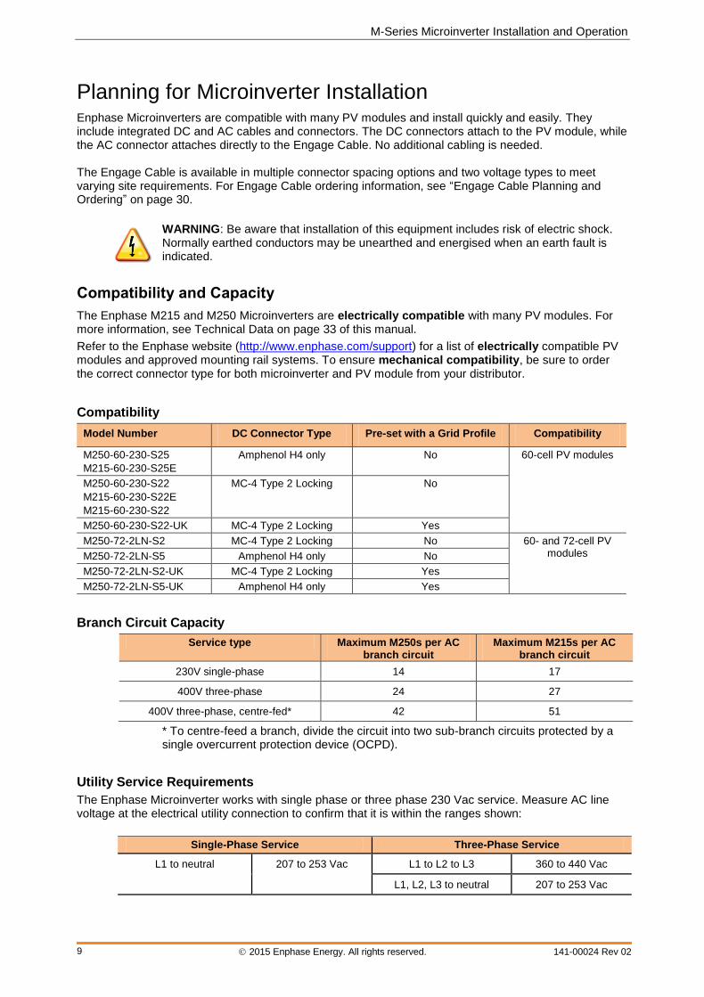
Compatibility
Model Number DC Connector Type Pre-set with a Grid Profile Compatibility
M250-60-230-S25
M215-60-230-S25E
Amphenol H4 only No 60-cell PV modules
M250-60-230-S22
M215-60-230-S22E
M215-60-230-S22
MC-4 Type 2 Locking No
M250-60-230-S22-UK MC-4 Type 2 Locking Yes
M250-72-2LN-S2 MC-4 Type 2 Locking No 60- and 72-cell PV modules M250-72-2LN-S5 Amphenol H4 only No
M250-72-2LN-S2-UK MC-4 Type 2 Locking Yes
M250-72-2LN-S5-UK Amphenol H4 only Yes
Branch Circuit Capacity
Service type Maximum M250s per AC branch circuit
Maximum M215s per AC branch circuit
230V single-phase 14 17
400V three-phase 24 27
400V three-phase, centre-fed* 42 51
* To centre-feed a branch, divide the circuit into two sub-branch circuits protected by a single overcurrent protection device (OCPD).
Utility Service Requirements
The Enphase Microinverter works with single phase or three phase 230 Vac service. Measure AC line voltage at the electrical utility connection to confirm that it is within the ranges shown:
Single-Phase Service Three-Phase Service
L1 to neutral 207 to 253 Vac L1 to L2 to L3 360 to 440 Vac
L1, L2, L3 to neutral 207 to 253 Vac
Enphase Microinverter Installation and Operation
2015 Enphase Energy. All rights reserved. 141-00024 Rev 02
10
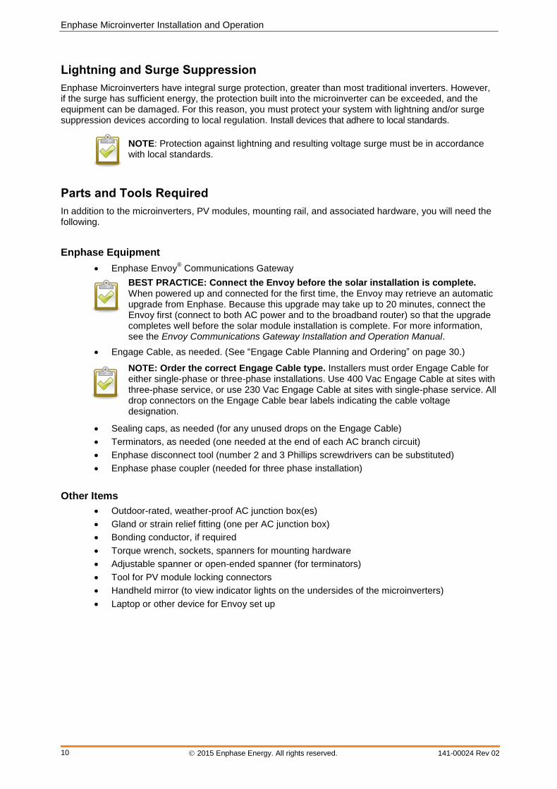
Lightning and Surge Suppression
Enphase Microinverters have integral surge protection, greater than most traditional inverters. However, if the surge has sufficient energy, the protection built into the microinverter can be exceeded, and the equipment can be damaged. For this reason, you must protect your system with lightning and/or surge suppression devices according to local regulation. Install devices that adhere to local standards.
NOTE: Protection against lightning and resulting voltage surge must be in accordance with local standards.
Parts and Tools Required
In addition to the microinverters, PV modules, mounting rail, and associated hardware, you will need the following.
Enphase Equipment
Enphase Envoy® Communications Gateway
BEST PRACTICE: Connect the Envoy before the solar installation is complete. When powered up and connected for the first time, the Envoy may retrieve an automatic upgrade from Enphase. Because this upgrade may take up to 20 minutes, connect the Envoy first (connect to both AC power and to the broadband router) so that the upgrade completes well before the solar module installation is complete. For more information, see the Envoy Communications Gateway Installation and Operation Manual.
Engage Cable, as needed. (See “Engage Cable Planning and Ordering” on page 30.)
NOTE: Order the correct Engage Cable type. Installers must order Engage Cable for either single-phase or three-phase installations. Use 400 Vac Engage Cable at sites with three-phase service, or use 230 Vac Engage Cable at sites with single-phase service. All drop connectors on the Engage Cable bear labels indicating the cable voltage designation.
Sealing caps, as needed (for any unused drops on the Engage Cable)
Terminators, as needed (one needed at the end of each AC branch circuit)
Enphase disconnect tool (number 2 and 3 Phillips screwdrivers can be substituted)
Enphase phase coupler (needed for three phase installation)
Other Items
Outdoor-rated, weather-proof AC junction box(es)
Gland or strain relief fitting (one per AC junction box)
Bonding conductor, if required
Torque wrench, sockets, spanners for mounting hardware
Adjustable spanner or open-ended spanner (for terminators)
Tool for PV module locking connectors
Handheld mirror (to view indicator lights on the undersides of the microinverters)
Laptop or other device for Envoy set up
M-Series Microinverter Installation and Operation
2015 Enphase Energy. All rights reserved. 141-00024 Rev 02
11
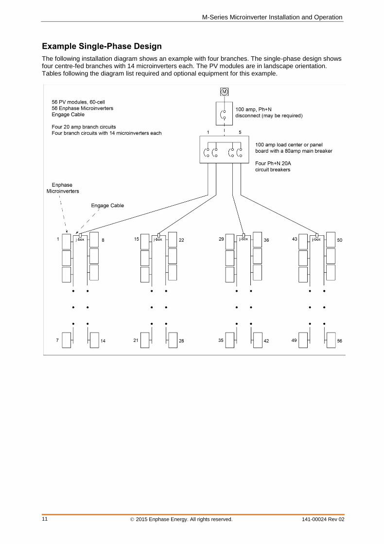
Example Single-Phase Design
The following installation diagram shows an example with four branches. The single-phase design shows four centre-fed branches with 14 microinverters each. The PV modules are in landscape orientation. Tables following the diagram list required and optional equipment for this example.

Enphase Microinverter Installation and Operation
2015 Enphase Energy. All rights reserved. 141-00024 Rev 02
12
Enphase Items Needed for Example Design
Quantity Description Order Number
56 M215 or M250 Microinverters See page 9 for model numbers
1 pack Disconnect tool (each pack contains five tools) ET-DISC-05
1 pack Branch Terminator (each pack contains 10 terminators) ET-TERM-10
1 Engage Cable
ET17-230-xxx or ET21-230-192-2.5mm (minimum 56 drops)
1 pack
Sealing caps (each pack contains 10 caps): Required only if there are any unused connectors on the Engage Cable; Unused connectors must be covered with this cap.
ET-SEAL-10
1 Envoy Communications Gateway ENV-230
optional Power line communication bridge pair EPLC-02 (EU), EPLC-03 (UK) or EPLC-04 (AU)
optional Wireless N USB adapter (802.11b/g/n) WF-01
Non-Enphase Items Needed for Example Design
Quantity Description
56 60-cell PV modules
as needed Tie wraps (cable ties)
4 Weather-proof junction box
4 20 amp circuit breaker single pole / Ph+N
1 (optional) 100 amp circuit breaker
1 100 amp load centre with 1 80 amp main breaker
as needed Rail / mounting hardware
as needed Lightning protection device
as needed Homerun conductors
as needed Continuous earthing conductor
as needed Torque wrench, sockets, wrenches for mounting hardware
as needed Adjustable wrench or open-ended wrench (for terminator caps)
as needed Inspection mirror (for viewing indicator lights on the undersides of the microinverters)

M-Series Microinverter Installation and Operation
2015 Enphase Energy. All rights reserved. 141-00024 Rev 02
13
Enphase Microinverter Installation Installing the Enphase Microinverter System involves several key steps. Each step listed below is detailed in the following pages.
Step 1: Register the System
Step 2: Connect the Envoy® Communications Gateway™
Step 3: Position the Enphase Engage™ Cable
Step 4: Install an AC Junction Box
Step 5: Attach the Microinverters to the Mounting Rail
Step 6: Dress the Engage Cable
Step 7: Connect the Microinverters
Step 8: Terminate the Unused End of the Engage Cable Step 9: Connect the Engage Cable to AC Junction Box Step 10: Complete the Installation Map Step 11: Connect the PV Modules
WARNING: Risk of electric shock. Risk of fire. Always de-energise the AC branch circuit before servicing. Never disconnect the DC connectors under load.
WARNING: DO NOT connect Enphase Microinverters to the electricity network or energise the AC circuit(s) until you have completed all of the installation procedures as described in the following sections.
NOTE: Some Enphase Microinverters will not begin exporting power until the Envoy Communications Gateway is installed and has detected all of the microinverters at the site. In addition, the grid profile must be configured and the Envoy must have propagated these settings to the microinverters. For instructions on this procedure, refer to the Envoy Installation and Operation Manual at http://www.enphase.com/support.
Enphase Microinverter Installation and Operation
2015 Enphase Energy. All rights reserved. 141-00024 Rev 02
14
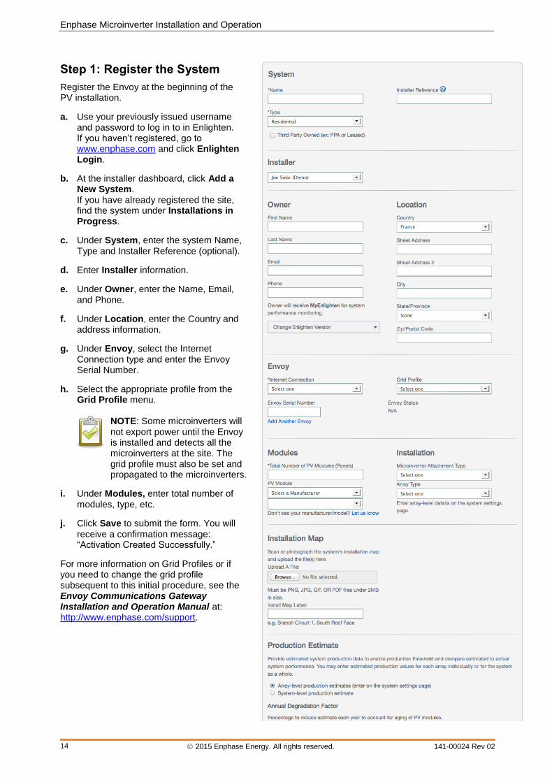
Step 1: Register the System
Register the Envoy at the beginning of the PV installation.
a. Use your previously issued username and password to log in to in Enlighten. If you haven’t registered, go to www.enphase.com and click Enlighten Login.
b. At the installer dashboard, click Add a New System. If you have already registered the site, find the system under Installations in Progress.
c. Under System, enter the system Name, Type and Installer Reference (optional).
d. Enter Installer information.
e. Under Owner, enter the Name, Email, and Phone.
f. Under Location, enter the Country and address information.
g. Under Envoy, select the Internet Connection type and enter the Envoy Serial Number.
h. Select the appropriate profile from the Grid Profile menu.
NOTE: Some microinverters will not export power until the Envoy is installed and detects all the microinverters at the site. The grid profile must also be set and propagated to the microinverters.
i. Under Modules, enter total number of modules, type, etc.
j. Click Save to submit the form. You will receive a confirmation message: “Activation Created Successfully.”
For more information on Grid Profiles or if you need to change the grid profile subsequent to this initial procedure, see the Envoy Communications Gateway Installation and Operation Manual at: http://www.enphase.com/support.
M-Series Microinverter Installation and Operation
2015 Enphase Energy. All rights reserved. 141-00024 Rev 02
15
Step 2: Connect the Envoy Communications Gateway
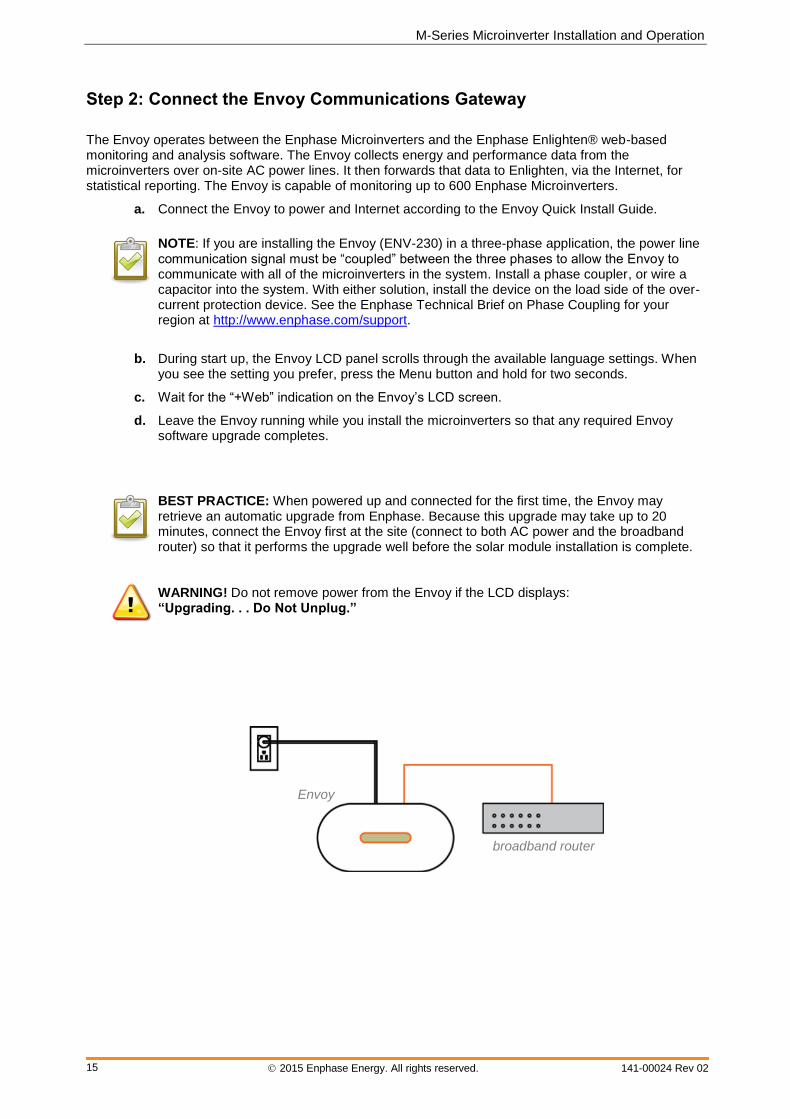
The Envoy operates between the Enphase Microinverters and the Enphase Enlighten® web-based monitoring and analysis software. The Envoy collects energy and performance data from the microinverters over on-site AC power lines. It then forwards that data to Enlighten, via the Internet, for statistical reporting. The Envoy is capable of monitoring up to 600 Enphase Microinverters.
a. Connect the Envoy to power and Internet according to the Envoy Quick Install Guide.
NOTE: If you are installing the Envoy (ENV-230) in a three-phase application, the power line communication signal must be “coupled” between the three phases to allow the Envoy to communicate with all of the microinverters in the system. Install a phase coupler, or wire a capacitor into the system. With either solution, install the device on the load side of the over-current protection device. See the Enphase Technical Brief on Phase Coupling for your region at http://www.enphase.com/support.
b. During start up, the Envoy LCD panel scrolls through the available language settings. When you see the setting you prefer, press the Menu button and hold for two seconds.
c. Wait for the “+Web” indication on the Envoy’s LCD screen.
d. Leave the Envoy running while you install the microinverters so that any required Envoy software upgrade completes.
BEST PRACTICE: When powered up and connected for the first time, the Envoy may retrieve an automatic upgrade from Enphase. Because this upgrade may take up to 20 minutes, connect the Envoy first at the site (connect to both AC power and the broadband router) so that it performs the upgrade well before the solar module installation is complete.
WARNING! Do not remove power from the Envoy if the LCD displays: “Upgrading. . . Do Not Unplug.”
broadband router
Envoy
Enphase Microinverter Installation and Operation
2015 Enphase Energy. All rights reserved. 141-00024 Rev 02
16
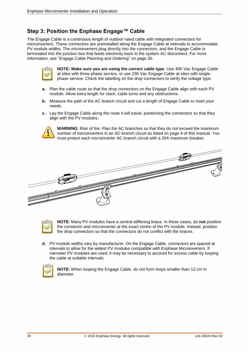
Step 3: Position the Enphase Engage™ Cable
The Engage Cable is a continuous length of outdoor rated cable with integrated connectors for microinverters. These connectors are preinstalled along the Engage Cable at intervals to accommodate PV module widths. The microinverters plug directly into the connectors, and the Engage Cable is terminated into the junction box that feeds electricity back to the system AC disconnect. For more information, see “Engage Cable Planning and Ordering” on page 30.
NOTE: Make sure you are using the correct cable type. Use 400 Vac Engage Cable at sites with three-phase service, or use 230 Vac Engage Cable at sites with single-phase service. Check the labelling on the drop connectors to verify the voltage type.
a. Plan the cable route so that the drop connectors on the Engage Cable align with each PV
module. Allow extra length for slack, cable turns and any obstructions.
b. Measure the path of the AC branch circuit and cut a length of Engage Cable to meet your needs.
c. Lay the Engage Cable along the route it will travel, positioning the connectors so that they align with the PV modules.
WARNING: Risk of fire. Plan the AC branches so that they do not exceed the maximum number of microinverters in an AC branch circuit as listed on page 9 of this manual. You must protect each microinverter AC branch circuit with a 20A maximum breaker.
NOTE: Many PV modules have a central stiffening brace. In these cases, do not position the connector and microinverter at the exact centre of the PV module. Instead, position the drop connectors so that the connectors do not conflict with the braces.
d. PV module widths vary by manufacturer. On the Engage Cable, connectors are spaced at intervals to allow for the widest PV modules compatible with Enphase Microinverters. If narrower PV modules are used, it may be necessary to account for excess cable by looping the cable at suitable intervals.
NOTE: When looping the Engage Cable, do not form loops smaller than 12 cm in diameter.
M-Series Microinverter Installation and Operation
2015 Enphase Energy. All rights reserved. 141-00024 Rev 02
17
Step 4: Install an AC Junction Box
DANGER: Risk of electric shock. Be aware that installation of this equipment includes risk of electric shock. Do not install the AC junction box without first removing AC power from the Enphase System.
WARNING: Only use electrical system components approved for wet locations.
WARNING: Do NOT exceed the maximum number of microinverters in an AC branch circuit as listed on page 9 of this manual.
a. Install an appropriate junction box at a suitable location on the mounting system. You can centre feed the branch, or you can install the junction box at the end of a row of PV modules.
Best Practice: Centre-feed the branch circuit to minimise voltage rise in a fully-populated branch. This practice greatly reduces the voltage rise as compared with an end-fed branch. To centre-feed a branch, divide the circuit into two sub-branch circuits protected by a single overcurrent protection device (OCPD).
b. Size the AC cable/wire size to account for voltage drop. Select conductor diameter based on
the distance from the beginning of the microinverter AC branch circuit to the breaker in the AC mains.
All components of system wiring must be considered, including internal voltage drop within the length of Engage Cable. Typically, three wire sections and several wire terminations must be quantified. There is also some resistance associated with each circuit breaker. As all of these resistances are in series, they add together. Since the same current is flowing through each resistance, the total voltage drop is total current times the total resistance. For a single-phase system, the total resistance is equal to two times the one-way resistance. For a three-phase system, each of the three line currents and resistances must be calculated.
Standard guidelines for voltage drop on feeder and AC branch circuit conductors might not be sufficient for microinverter AC branch circuits that contain the maximum allowable microinverters. This is due to high inherent voltage rise on the AC branch circuit.
For more information, refer to our Technical Briefs on Voltage Drop at http://www.enphase.com/support.
c. Provide an AC connection from the AC junction box back to the electricity network connection using equipment and practices as required by local regulations.
Enphase Microinverter Installation and Operation
2015 Enphase Energy. All rights reserved. 141-00024 Rev 02
18
Step 5: Attach the Microinverters to the Mounting Rail
a. Mark the approximate centres of each PV module on the mounting rail.
b. Evaluate the location of the microinverter with respect to the PV module DC junction box or any other obstructions.
c. Ensure that the microinverter does not interfere with the PV module frame or stiffening braces.
d. Ensure that the connector from the microinverter can easily reach the connector on the Engage Cable.
e. Allow a minimum of 1.9 cm (0.75 inches) between the roof and the bottom of the microinverter. Also allow 1.3 cm (0.50 inches) between the back of the PV module and the top of the microinverter.
WARNING: Risk of equipment damage. You must install the microinverter under the module, out of rain and sun. Do not mount the microinverter in a position that allows long-term exposure to direct sunlight or in a vertical orientation that allows water to collect in the DC connector recess. Do not install the microinverter black-side up or vertically, with the DC connectors facing up.
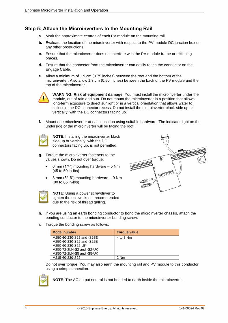
f. Mount one microinverter at each location using suitable hardware. The indicator light on the
underside of the microinverter will be facing the roof.
NOTE: Installing the microinverter black side up or vertically, with the DC connectors facing up, is not permitted.
g. Torque the microinverter fasteners to the
values shown. Do not over torque.
6 mm (1/4”) mounting hardware – 5 Nm (45 to 50 in-lbs)
8 mm (5/16”) mounting hardware – 9 Nm (80 to 85 in-lbs)
NOTE: Using a power screwdriver to tighten the screws is not recommended due to the risk of thread galling.
h. If you are using an earth bonding conductor to bond the microinverter chassis, attach the bonding conductor to the microinverter bonding screw.
i. Torque the bonding screw as follows:
Model number Torque value
M250-60-230-S25 and -S25E M250-60-230-S22 and -S22E M250-60-230-S22-UK M250-72-2LN-S2 and -S2-UK M250-72-2LN-S5 and -S5-UK
4 to 5 Nm
M215-60-230-S22 2 Nm
Do not over torque. You may also earth the mounting rail and PV module to this conductor using a crimp connection.
NOTE: The AC output neutral is not bonded to earth inside the microinverter.
M-Series Microinverter Installation and Operation
2015 Enphase Energy. All rights reserved. 141-00024 Rev 02
19
Step 6: Dress the Engage Cable
NOTE: Adhere to the following requirements:
Do not expose the cable connections to directed, pressurised liquid (water jets, etc.).
Do not expose the cable connections to continuous immersion.
Do not expose the AC connector to continuous tension (e.g., tension due to pulling or bending the cable near the connection)
Use only the connectors and cables provided.
Do not allow contamination or debris in the connectors.
Use the cable and connectors only when all parts are present and intact.
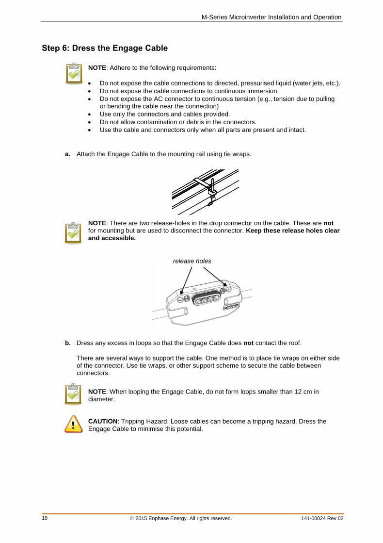
a. Attach the Engage Cable to the mounting rail using tie wraps.
NOTE: There are two release-holes in the drop connector on the cable. These are not for mounting but are used to disconnect the connector. Keep these release holes clear and accessible.
b. Dress any excess in loops so that the Engage Cable does not contact the roof.
There are several ways to support the cable. One method is to place tie wraps on either side of the connector. Use tie wraps, or other support scheme to secure the cable between connectors.
NOTE: When looping the Engage Cable, do not form loops smaller than 12 cm in diameter.
CAUTION: Tripping Hazard. Loose cables can become a tripping hazard. Dress the Engage Cable to minimise this potential.
release holes
Enphase Microinverter Installation and Operation
2015 Enphase Energy. All rights reserved. 141-00024 Rev 02
20
Step 7: Connect the Microinverters
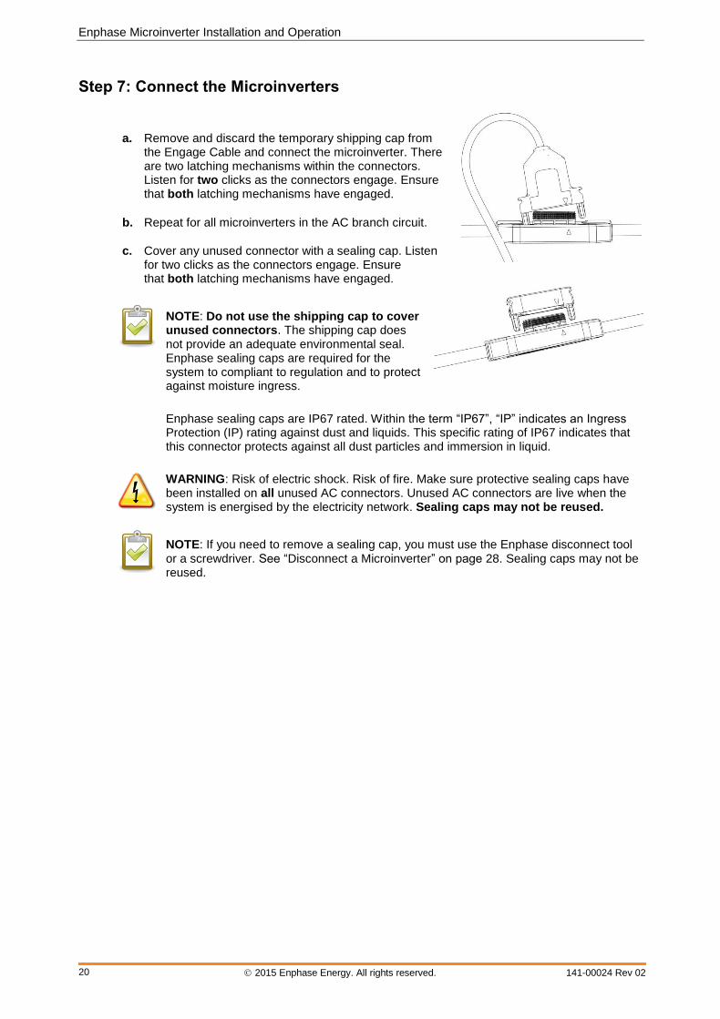
a. Remove and discard the temporary shipping cap from the Engage Cable and connect the microinverter. There are two latching mechanisms within the connectors. Listen for two clicks as the connectors engage. Ensure that both latching mechanisms have engaged.
b. Repeat for all microinverters in the AC branch circuit.
c. Cover any unused connector with a sealing cap. Listen for two clicks as the connectors engage. Ensure that both latching mechanisms have engaged.
NOTE: Do not use the shipping cap to cover unused connectors. The shipping cap does not provide an adequate environmental seal. Enphase sealing caps are required for the system to compliant to regulation and to protect against moisture ingress.
Enphase sealing caps are IP67 rated. Within the term “IP67”, “IP” indicates an Ingress Protection (IP) rating against dust and liquids. This specific rating of IP67 indicates that this connector protects against all dust particles and immersion in liquid.
WARNING: Risk of electric shock. Risk of fire. Make sure protective sealing caps have been installed on all unused AC connectors. Unused AC connectors are live when the system is energised by the electricity network. Sealing caps may not be reused.
NOTE: If you need to remove a sealing cap, you must use the Enphase disconnect tool or a screwdriver. See “Disconnect a Microinverter” on page 28. Sealing caps may not be reused.

M-Series Microinverter Installation and Operation
2015 Enphase Energy. All rights reserved. 141-00024 Rev 02
21
Step 8: Terminate the Unused End of the Engage Cable
WARNING: Risk of Electrical Shock. Do not install the terminator cap while power is connected.
Terminate the far end of the Engage Cable as follows.
a. Remove 60mm (2.5 inches) of the cable sheath from the conductors.
b. Slide the hex nut onto the Engage Cable.
c. Insert the Engage Cable all the way into the wire organiser (up to the stop).
d. Bend the individual wires back into the recesses in the wire organiser so that they angle back toward the cable.
e. Cut the individual wires so that no excess extends outside of the wire organiser. The portions that angle back will need to extend enough to fit neatly into the 0.5 cm (0.2 in) recesses in the wire organiser and flush with the edge of the cap.
f. Place cap over the wire organiser.
g. Hold the cap with an Enphase disconnect tool, or insert a #2 Phillips screwdriver.
h. Use a 22 mm (7/8 inch) spanner to tighten the hex nut until the latching mechanism is screwed all the way to the base. Never unscrew the hex nut as this can twist and damage the cable.
i. Use a tie wrap to attach the cable to the mounting rail, so that the Engage Cable and terminator do not touch the roof.
j. Ensure that all cabling is located underneath the PV module.
hex nut wire organiser cap

Enphase Microinverter Installation and Operation
2015 Enphase Energy. All rights reserved. 141-00024 Rev 02
22
Step 9: Connect the Engage Cable to AC Junction Box
a. Connect Engage Cable into the AC branch circuit junction box using an appropriate gland or strain relief fitting. The Engage Cable requires a strain relief connector with an opening of 1.3 cm (0.5 inches) in diameter.
b. Connect the Engage Cable into additional AC junction boxes as needed to transition to conduit between smaller sub-arrays.
Refer to the schematics located on page 40 for more information.
Single-phase 230 Vac Three-phase 400 Vac
L1 - Brown L1 - Brown
(not present) L2 - Black
(not present) L3 - Grey
Neutral - Blue Neutral - Blue
Earth – Green / yellow (acts as equipment earth)
Earth – Green / yellow (acts as equipment earth)
Balanced 400 Vac (3-phase) is accomplished by alternating phases between microinverters as shown:
WARNING: Risk of electric shock. Treat all connector contacts as though they are live. The 400 Vac Engage Cable drop connector contains two live phases.
M-Series Microinverter Installation and Operation
2015 Enphase Energy. All rights reserved. 141-00024 Rev 02
23
Step 10: Complete the Installation Map
The Enphase Installation Map is a diagrammatic representation of the physical location of each microinverter in your PV installation. You will create the virtual array in Enlighten from this map. Use the blank map on page 39 to record microinverter placement for the system, or provide your own layout if a larger or more intricate installation map is required.
You can build the system map manually, by peeling the serial number labels from the microinverters and placing the labels on the installation map, or you can use the scanning tool feature from the Enphase Installer Toolkit to easily build and configure a system. Refer to http://enphase.com/installer-toolkit/ for more information.
To manually build the Installation Map:
Each Enphase Microinverter has a removable serial number label located on the mounting plate. Peel the removable serial number label from each Enphase Microinverter and affix it to the respective location on the Enphase installation map (see map on page 39). Remember to keep a copy of the installation map for your records.
Draw a top-down view of the array using the Array Map template. Make sure to leave enough room to place the serial number stickers.
When installing the microinverters, remove the serial number labels located next to the DC input cables and place them in the correct order on your drawing of the system. Remember to keep a copy of the installation map for your records.
Step 11: Connect the PV Modules
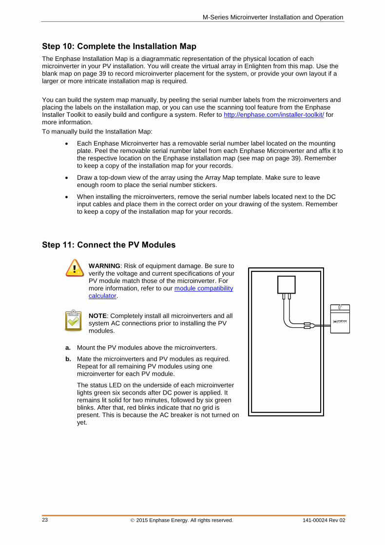
WARNING: Risk of equipment damage. Be sure to verify the voltage and current specifications of your PV module match those of the microinverter. For more information, refer to our module compatibility calculator.
NOTE: Completely install all microinverters and all system AC connections prior to installing the PV modules.
a. Mount the PV modules above the microinverters.
b. Mate the microinverters and PV modules as required. Repeat for all remaining PV modules using one microinverter for each PV module.
The status LED on the underside of each microinverter lights green six seconds after DC power is applied. It remains lit solid for two minutes, followed by six green blinks. After that, red blinks indicate that no grid is present. This is because the AC breaker is not turned on yet.

Enphase Microinverter Installation and Operation
2015 Enphase Energy. All rights reserved. 141-00024 Rev 02
24
Commissioning and Operation
WARNING: Risk of electric shock. Risk of fire. Qualified personnel only may connect the Enphase Microinverter to the electricity network.
WARNING: Risk of electric shock. Risk of fire. Ensure that all AC and DC wiring is correct. Ensure that none of the AC and DC wires are pinched or damaged. Ensure that all AC junction boxes are properly closed.
REMINDER: Enphase Microinverters will not begin exporting power until the Envoy Communications Gateway is installed and has detected all of the microinverters at the site. In addition, the grid profile must be configured and the Envoy must have propagated these settings to the microinverters.
For instructions on installing the Envoy and configuring the grid profile, refer to the Envoy Installation and Operation Manual at http://www.enphase.com/support.
Energise the System
1. Turn ON the AC disconnect or circuit breaker (such as an isolation switch) for each microinverter AC branch circuit.
2. Turn ON the main AC switch.
3. The Enphase Microinverters will begin communicating over the power lines to the Envoy. The time required for the Envoy to discover all of the microinverters varies with the number of microinverters in the system and quality of the power line communications. At a typical residential installation, all of the microinverters are detected within 15 minutes. Large systems of 250 to 600 microinverters typically take one to two hours to detect all of the microinverters.
4. If not done in Step 1, you may need to configure the microinverters with the appropriate grid profile before they can produce power. For instructions on this procedure, refer to the Envoy Installation and Operation Manual at http://www.enphase.com/support.
NOTE: If the Envoy has not been set up with a grid profile for the microinverters, the microinverters may not produce energy. Most microinverters must be configured with the appropriate grid profile as part of the commissioning process.
Check the Envoy's progress
Refer to the Envoy Communications Gateway Installation and Operation Manual at http://www.enphase.com/support for details on the following steps.
1. An automatic device scan runs for eight hours after the Envoy is installed. If this scan has expired, start a new scan.
• Press and hold the Envoy menu button (on the right side of the Envoy).
• Release the menu button when the LCD displays Enable Device Scan.
2. Check that the Envoy LCD shows a complete device count after about 30 minutes.
3. Check power line communications as shown by the number of bars on the Envoy LCD.
• Press and hold the Envoy menu button (on the right side of the Envoy).
• Release the menu button when the LCD displays Enable Communication Check.
4. Use the Envoy menu button to stop the scan when all devices are detected:
• Press and hold the Envoy menu button (on the right side of the Envoy).
• Release the menu button when the LCD displays Disable Device Scan.

M-Series Microinverter Installation and Operation
2015 Enphase Energy. All rights reserved. 141-00024 Rev 02
25
Configure the Grid Profile
If you did not set the Grid Profile during registration or if you need to change the Grid Profile, use the Envoy interface to configure the Grid Profile (alternate voltage and frequency trip points) for the system. Refer to the Envoy Communications Gateway Installation and Operation Manual at http://www.enphase.com/support for instructions.
Build the Virtual Array
When the system is energised and the Envoy detects all the installed microinverters, you can create the virtual array in Enlighten from the installation map you created. Once the virtual array is built, Enlighten displays a graphic representation of the PV system. It also shows detailed current and historical performance information. Go to http://www.enphase.com for more information on the Enphase Enlighten web-based monitoring and analysis.
To scan and upload the map and build the array:
1. Scan the installation map and upload it to the Activation form online.
2. Use Array Builder to create the virtual array in Enlighten. Use your installation map as your reference.
NOTE: Go to http://enphase.com/support/videos/ to view the Array Builder demo.
3. If you do not already have an account, go to http://www.enphase.com and click “Enlighten Login” to register.
Enphase Microinverter Installation and Operation
2015 Enphase Energy. All rights reserved. 141-00024 Rev 02
26
Troubleshooting Adhere to all the safety measures described throughout this manual. Qualified personnel can use the following troubleshooting steps if the PV system does not operate correctly.
WARNING: Risk of electric shock. Do not attempt to repair the Enphase Microinverter; it contains no user-serviceable parts. If it fails, contact Enphase customer service to obtain an RMA (return merchandise authorisation) number and start the replacement process.
Status LED Indications and Error Reporting
Start-up LED Operation
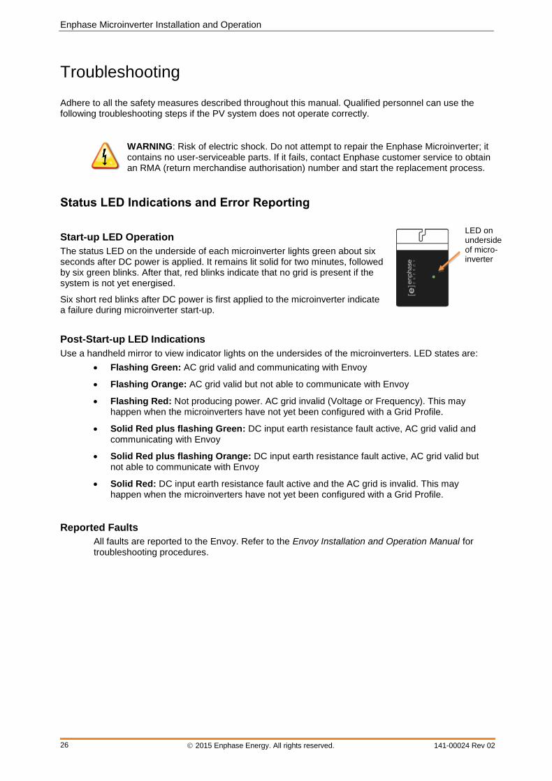
The status LED on the underside of each microinverter lights green about six seconds after DC power is applied. It remains lit solid for two minutes, followed by six green blinks. After that, red blinks indicate that no grid is present if the system is not yet energised.
Six short red blinks after DC power is first applied to the microinverter indicate a failure during microinverter start-up.
Post-Start-up LED Indications
Use a handheld mirror to view indicator lights on the undersides of the microinverters. LED states are:
Flashing Green: AC grid valid and communicating with Envoy
Flashing Orange: AC grid valid but not able to communicate with Envoy
Flashing Red: Not producing power. AC grid invalid (Voltage or Frequency). This may happen when the microinverters have not yet been configured with a Grid Profile.
Solid Red plus flashing Green: DC input earth resistance fault active, AC grid valid and communicating with Envoy
Solid Red plus flashing Orange: DC input earth resistance fault active, AC grid valid but not able to communicate with Envoy
Solid Red: DC input earth resistance fault active and the AC grid is invalid. This may happen when the microinverters have not yet been configured with a Grid Profile.
Reported Faults
All faults are reported to the Envoy. Refer to the Envoy Installation and Operation Manual for troubleshooting procedures.
LED on underside of micro-inverter

M-Series Microinverter Installation and Operation
2015 Enphase Energy. All rights reserved. 141-00024 Rev 02
27
Troubleshoot an Inoperable Microinverter
To troubleshoot an inoperable microinverter, follow the steps in the order shown.
WARNING: Risk of electric shock. Always de-energise the AC branch circuit before servicing. Never disconnect the DC connectors under load.
CAUTION: The Enphase Microinverters are powered by DC power from the PV modules. Make sure you disconnect the DC connections and reconnect DC power to watch for the solid green about six seconds after connection to DC power and then six short green LED blinks two minutes after connection to DC power.
1. Make sure AC breakers and disconnects are closed.
2. Check the connection to the electricity network and verify the utility voltage and frequency are within allowable ranges.
3. Verify that AC line voltages at all solar power circuit breakers at the AC mains and subpanels are within the ranges shown in the following table.
4. Verify that AC line voltage at the electrical distribution board or consumer unit and at the AC junction box for each AC branch circuit are within the ranges are shown in the following table:
Single-phase service Three-phase service
L1 to neutral 207 to 253 Vac L1 to L2 to L3 360 to 440 Vac
L1, L2, L3 to neutral 207 to 253 Vac
5. Using an Enphase disconnect tool, disconnect the AC cable for the microinverter in question from the Engage Cable.
6. Verify that utility power is present at the microinverter by measuring line to neutral at the Engage Cable connector.
7. Visually check that the AC branch circuit connections (Engage Cable and AC connections) are properly seated. Reseat if necessary. Check also for damage, such as rodent damage.
8. Make sure that any upstream AC disconnects, as well as the dedicated circuit breakers for each AC branch circuit, are functioning properly and are closed.
9. Disconnect and re-connect the DC PV module connectors. The Status LED of each microinverter will light solid green a few seconds after connection to DC power and then blink green six times to indicate normal start-up operation about two minutes after connecting to DC power. The LED subsequently resumes normal operation if the grid is present. See page 26 for normal LED operation.
10. Attach an ammeter clamp to one conductor of the DC cables from the PV module to measure microinverter current. This will be under one Amp if AC is disconnected.
11. Verify the PV module DC voltage is within the allowable range for the microinverter, as shown in “Technical Data” on page 33 of this manual.
12. Swap DC leads with a known good, adjacent PV module. If after checking Enlighten periodically (this may take up to 30 minutes), the problem moves to the adjacent module, this indicates that the PV module isn’t functioning correctly. If it stays in place, the problem is with the microinverter. Call Enphase Customer Support for help in reading the microinverter data and for help in obtaining a replacement microinverter, if needed.
13. Check the DC connections between the microinverter and the PV module. The connection may need to be tightened or reseated. If the connection is worn or damaged, it may need replacement.
14. Verify with your electricity network that line frequency is within range.
15. If the problem persists, contact Customer Support at [email protected].
Enphase Microinverter Installation and Operation
2015 Enphase Energy. All rights reserved. 141-00024 Rev 02
28
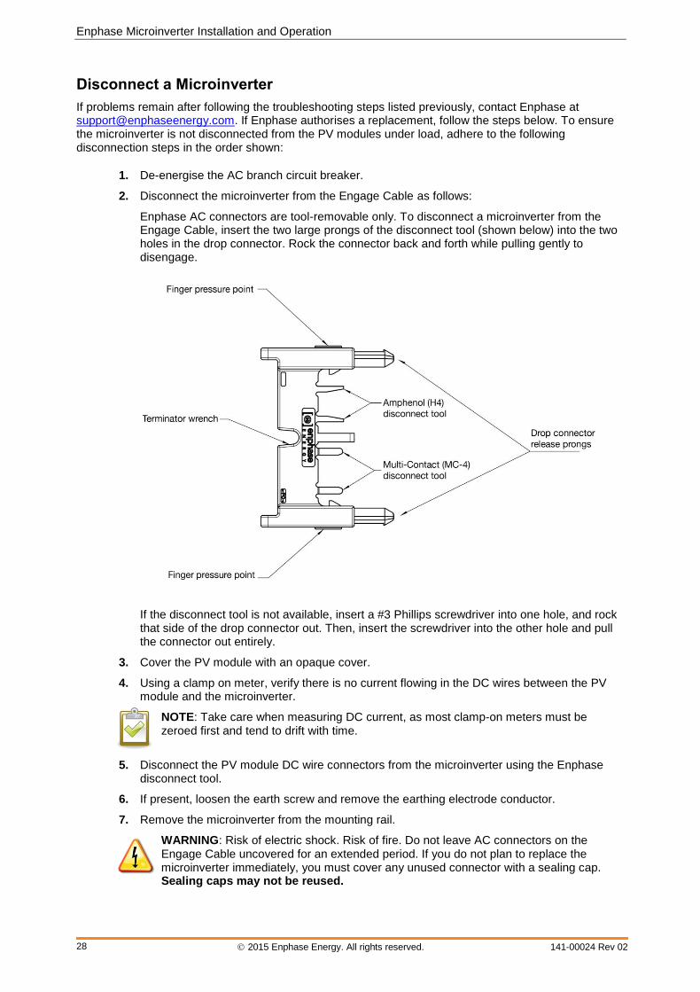
Disconnect a Microinverter
If problems remain after following the troubleshooting steps listed previously, contact Enphase at [email protected]. If Enphase authorises a replacement, follow the steps below. To ensure the microinverter is not disconnected from the PV modules under load, adhere to the following disconnection steps in the order shown:
1. De-energise the AC branch circuit breaker.
2. Disconnect the microinverter from the Engage Cable as follows:
Enphase AC connectors are tool-removable only. To disconnect a microinverter from the Engage Cable, insert the two large prongs of the disconnect tool (shown below) into the two holes in the drop connector. Rock the connector back and forth while pulling gently to disengage.
If the disconnect tool is not available, insert a #3 Phillips screwdriver into one hole, and rock that side of the drop connector out. Then, insert the screwdriver into the other hole and pull the connector out entirely.
3. Cover the PV module with an opaque cover.
4. Using a clamp on meter, verify there is no current flowing in the DC wires between the PV module and the microinverter.
NOTE: Take care when measuring DC current, as most clamp-on meters must be zeroed first and tend to drift with time.
5. Disconnect the PV module DC wire connectors from the microinverter using the Enphase disconnect tool.
6. If present, loosen the earth screw and remove the earthing electrode conductor.
7. Remove the microinverter from the mounting rail.
WARNING: Risk of electric shock. Risk of fire. Do not leave AC connectors on the Engage Cable uncovered for an extended period. If you do not plan to replace the microinverter immediately, you must cover any unused connector with a sealing cap. Sealing caps may not be reused.

M-Series Microinverter Installation and Operation
2015 Enphase Energy. All rights reserved. 141-00024 Rev 02
29
Install a Replacement Microinverter
If problems remain after troubleshooting, contact Enphase at [email protected]. If Enphase authorises a replacement (RMA), replace the microinverter as follows:
1. When the replacement microinverter is available, verify that the AC branch circuit breaker is de-energised.
2. Attach the replacement microinverter to the mounting rail using hardware recommended by your mounting rail vendor.
WARNING: Risk of equipment damage. You must install the Enphase Microinverter under the module, out of rain and sun. Do not mount the microinverter in a position that allows long-term exposure to direct sunlight or in a vertical orientation that allows water to collect in the DC connector recess. Do not install the microinverter black-side up or vertically, with the DC connectors facing up.
3. Torque the microinverter fasteners to the values below. Do not over torque.
6 mm (1/4”) mounting hardware – 5 Nm (45 in-lbs)
8 mm (5/16”) mounting hardware – 9 Nm (80 in-lbs)
NOTE: Using a power screwdriver to tighten the fasteners is not recommended due to the risk of thread galling.
4. If you are using the bonding screw to bond the microinverter chassis, attach the bonding conductor to the screw. Torque the bonding screw as follows:
Model number Torque value
M250-60-230-S25 and -S25E M250-60-230-S22 and -S22E M250-60-230-S22-UK M250-72-2LN-S2 and -S2-UK M250-72-2LN-S5 and -S5-UK
4 to 5 Nm
M215-60-230-S22 2 Nm
Do not over torque.
NOTE: Using a power screwdriver to tighten the bonding screw is not recommended due to the risk of thread galling.
5. Attach the bonding conductor, if used, to the microinverter bonding screw.
6. Connect the microinverter to the Engage Cable drop connector. There are two latching mechanisms within the connectors. Listen for two clicks as the connectors engage. Ensure that both latching mechanisms have engaged.
7. Mount the PV module above the microinverter.
8. Mate the microinverter and PV module as required.
9. Energise the AC branch circuit breaker, and verify operation of the replacement microinverter by checking the indicator light on the underside of the microinverter. You may need a handheld mirror to see the indicator light.
10. Initiate a device scan at the Envoy. To do this, press and hold the Menu button on the Envoy for two seconds to bring up the Envoy menu on the LCD window. When the LCD window displays “Enable Device Scan”, release the Menu button. This starts a 30-minute scan at the Envoy to discover the new microinverter.
11. Use Enlighten’s Array Builder to add the newly detected microinverter to the virtual array.
12. Ship the old microinverter to Enphase using the supplied return-shipping label.
Enphase Microinverter Installation and Operation
2015 Enphase Energy. All rights reserved. 141-00024 Rev 02
30
Engage Cable Planning and Ordering The Engage Cable is a continuous length of outdoor-rated cable with integrated connectors for microinverters. These connectors are preinstalled along the Engage Cable at intervals to accommodate varying PV module widths. The microinverters plug directly into the cable connectors. The cabling is compatible with a variety of PV racking systems. For a list of approved PV racking systems, refer to the PV Racking Compatibility document on the Enphase website (http://www.enphase.com/support).
Selecting Cable Type
Enphase Engage Cable is available in two different voltage types and multiple connector spacing options. Depending upon installer needs, the cable is also available in different lengths.
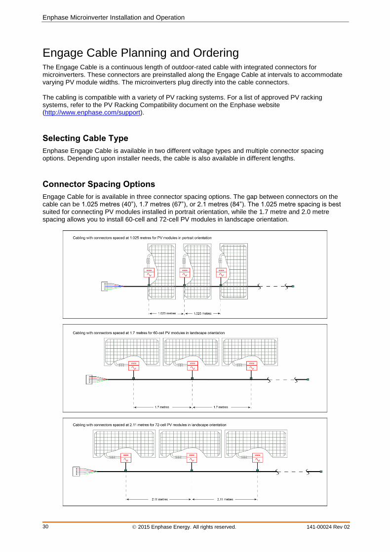
Connector Spacing Options
Engage Cable for is available in three connector spacing options. The gap between connectors on the cable can be 1.025 metres (40”), 1.7 metres (67”), or 2.1 metres (84”). The 1.025 metre spacing is best suited for connecting PV modules installed in portrait orientation, while the 1.7 metre and 2.0 metre spacing allows you to install 60-cell and 72-cell PV modules in landscape orientation.
M-Series Microinverter Installation and Operation
2015 Enphase Energy. All rights reserved. 141-00024 Rev 02
31
Voltage Type and Conductor Count Options
The voltage types are either single-phase or three-phase. All Engage Cable connectors bear labels indicating the voltage designation. Single-phase (230 Vac) Engage Cable includes three conductors. Three-phase (400 Vac) Engage Cable includes five conductors. Because Enphase microinverters output onto one phase, the 400 Vac Engage Cable balances the phases by rotating conductor use from one microinverter to the next as shown on page 22.
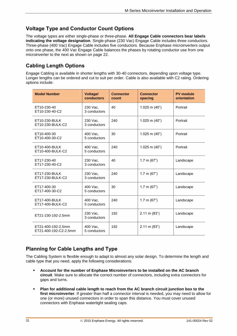
Cabling Length Options
Engage Cabling is available in shorter lengths with 30-40 connectors, depending upon voltage type. Longer lengths can be ordered and cut to suit per order. Cable is also available with C2 rating. Ordering options include:
Model Number Voltage/ conductors
Connector count
Connector spacing
PV module orientation
ET10-230-40 ET10-230-40-C2
230 Vac, 3 conductors
40 1.025 m (40”) Portrait
ET10-230-BULK ET10-230-BULK-C2
230 Vac, 3 conductors
240 1.025 m (40”) Portrait
ET10-400-30 ET10-400-30-C2
400 Vac, 5 conductors
30 1.025 m (40”) Portrait
ET10-400-BULK ET10-400-BULK-C2
400 Vac, 5 conductors
240 1.025 m (40”) Portrait
ET17-230-40 ET17-230-40-C2
230 Vac, 3 conductors
40 1.7 m (67”) Landscape
ET17-230-BULK ET17-230-BULK-C2
230 Vac, 3 conductors
240 1.7 m (67”) Landscape
ET17-400-30 ET17-400-30-C2
400 Vac, 5 conductors
30 1.7 m (67”) Landscape
ET17-400-BULK ET17-400-BULK-C2
400 Vac, 5 conductors
240 1.7 m (67”) Landscape
ET21-230-192-2.5mm 230 Vac, 3 conductors
192 2.11 m (83”) Landscape
ET21-400-192-2.5mm ET21-400-192-C2-2.5mm
400 Vac, 5 conductors
192 2.11 m (83”) Landscape
Planning for Cable Lengths and Type
The Cabling System is flexible enough to adapt to almost any solar design. To determine the length and cable type that you need, apply the following considerations:
Account for the number of Enphase Microinverters to be installed on the AC branch circuit. Make sure to allocate the correct number of connectors, including extra connectors for gaps and turns.
Plan for additional cable length to reach from the AC branch circuit junction box to the first microinverter. If greater than half a connector interval is needed, you may need to allow for one (or more) unused connectors in order to span this distance. You must cover unused connectors with Enphase watertight sealing caps.

Enphase Microinverter Installation and Operation
2015 Enphase Energy. All rights reserved. 141-00024 Rev 02
32
Minimise the number of unused Engage Cable connectors with three-phase systems. When cable connectors are left unused on a three-phase system, it creates a phase imbalance on the branch circuit. If multiple cable connectors are skipped over multiple branch circuits, the imbalance can multiply.
You can sometimes avoid skipping Engage Cable connectors by using Engage Couplers. Use the Engage Coupler to connect two Engage Cables or to connect Engage Cable to field cable.
There are many possible scenarios for each type of connection, but they generally fall into four categories:
Engage Cable to Engage Cable:
1. Make use of leftover lengths of Engage Cable
2. Transition between portrait and landscape Engage Cable
Engage Cable to Field Cable (such as Engage Cable, H07BQ-F, U-1000 RO2V, FG7OR, NYY-J)
3. Transition between sub-arrays on the same circuit
4. Create wiring extensions for Engage Cable
In situations where you cannot use an Engage Coupler, you can use an electrical junction box to transition between cable types.
Account for additional lengths of cable when calculating total voltage rise (voltage drop). Refer to the Technical Brief on Voltage Drop at http://www.enphase.com/support.
Plan for additional length to reach from one row of PV modules to the next. If the PV modules are laid out in multiple rows, the distance from one row to the next often requires additional cabling length.
Account for looping. When planning cabling turns or loops, do not form loops smaller than 12 cm in diameter.
Consider additional cabling when installing multiple sub-arrays. Often, an AC branch circuit may be composed of several smaller sub-arrays across more than one roof plane. In this case, cut the cable to service each smaller array, and connect the sub-arrays together using and Engage Coupler, or an appropriately rated AC junction box and conduit. Accomplish the transition from cable to conduit as required by local standards. Cover unused connectors with Enphase sealing caps.
Account for any mixture of PV modules in both portrait and landscape orientation. When PV modules are installed in mixed orientation (both portrait and landscape orientation), there are three choices for cabling:
1. Cabling with 1.025-metre spacing between connectors results in cleanest install for the PV modules in portrait orientation. For PV modules placed in landscape orientation, plan for an unused connector between each PV module to accommodate the required additional distance. Cover unused connectors with Enphase watertight sealing caps.
2. Cabling with 1.7-metre or 2.11-metre spacing between connectors results in cleanest install for PV modules in landscape orientation, but requires that any additional cable length between PV modules in portrait orientation be coiled and dressed so that cabling does not contact the roof. Cover unused connectors with Enphase watertight sealing caps.
3. Transition between 1.025 and 1.7-metre or 2.11-metre spaced cable using an outdoor-rated junction box. Install this junction box to the PV racking.
M-Series Microinverter Installation and Operation
2015 Enphase Energy. All rights reserved. 141-00024 Rev 02
33
Technical Data
Technical Considerations
Be sure to verify the voltage and current specifications of your PV module match those of the microinverter. For more information, refer to our module compatibility calculator.
WARNING: Risk of equipment damage. You must match the DC operating voltage range of the PV module with the allowable input voltage range of the Enphase Microinverter.
WARNING: Risk of equipment damage. The maximum open circuit voltage of the PV module must not exceed the specified maximum input voltage of the Enphase Microinverter.
The output voltage and current of the PV module depends on the quantity, size and temperature of the PV cells, as well as the insolation on each cell. The highest PV module output voltage occurs when the temperature of the cells is the lowest and the PV module is at open circuit (not operating). The maximum short circuit current rating of the PV module must be equal to or less than the maximum input DC short circuit current rating of the microinverter.
Features and Specifications
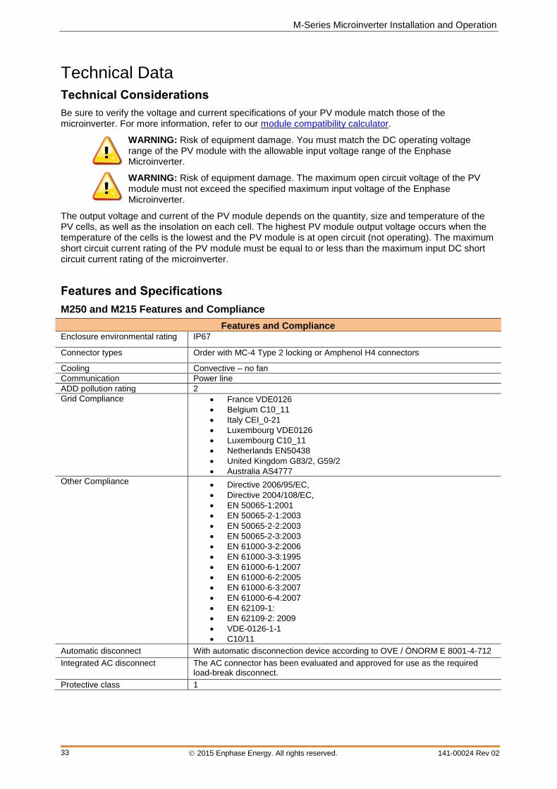
M250 and M215 Features and Compliance
Features and Compliance Enclosure environmental rating IP67
Connector types Order with MC-4 Type 2 locking or Amphenol H4 connectors
Cooling Convective – no fan
Communication Power line
ADD pollution rating 2
Grid Compliance France VDE0126
Belgium C10_11
Italy CEI_0-21
Luxembourg VDE0126
Luxembourg C10_11
Netherlands EN50438
United Kingdom G83/2, G59/2
Australia AS4777
Other Compliance Directive 2006/95/EC,
Directive 2004/108/EC,
EN 50065-1:2001
EN 50065-2-1:2003
EN 50065-2-2:2003
EN 50065-2-3:2003
EN 61000-3-2:2006
EN 61000-3-3:1995
EN 61000-6-1:2007
EN 61000-6-2:2005
EN 61000-6-3:2007
EN 61000-6-4:2007
EN 62109-1:
EN 62109-2: 2009
VDE-0126-1-1
C10/11
Automatic disconnect With automatic disconnection device according to OVE / ÖNORM E 8001-4-712
Integrated AC disconnect
The AC connector has been evaluated and approved for use as the required load-break disconnect.
Protective class 1
Enphase Microinverter Installation and Operation
2015 Enphase Energy. All rights reserved. 141-00024 Rev 02
34
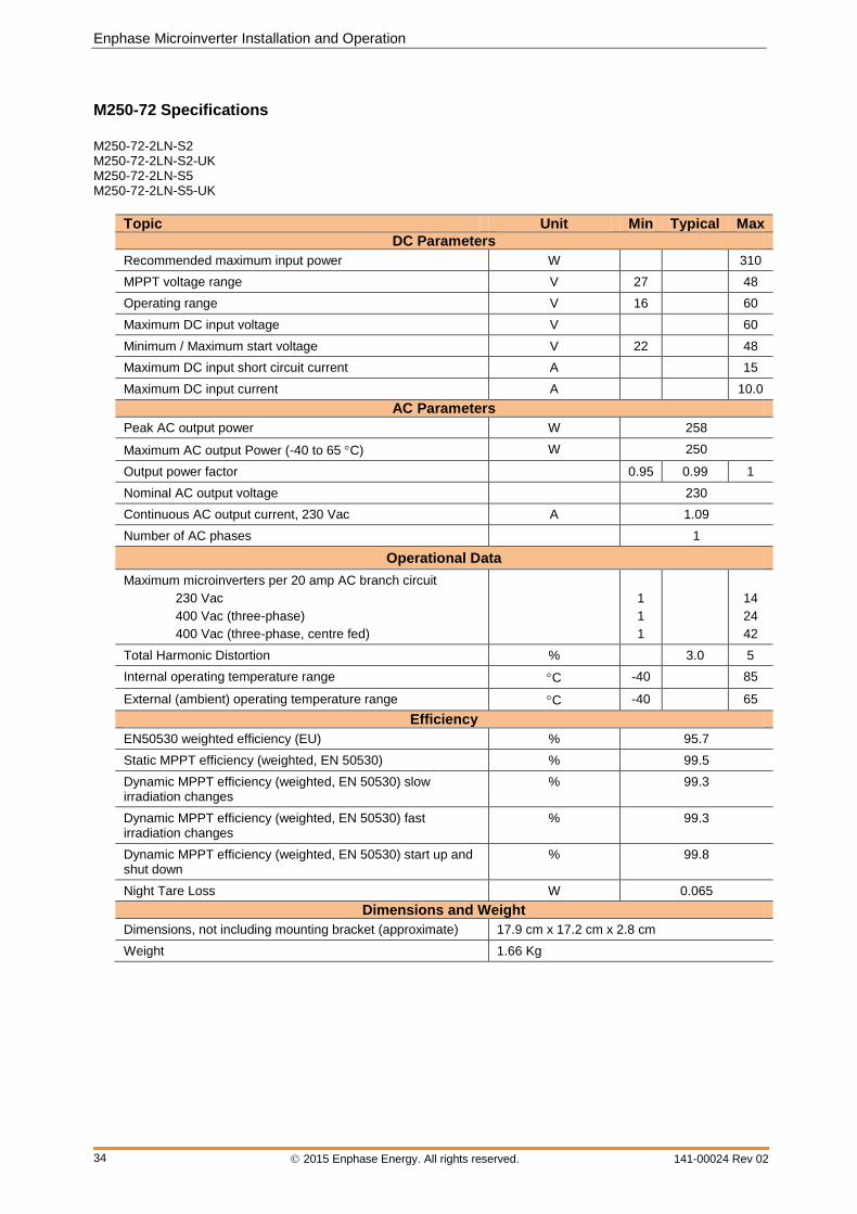
M250-72 Specifications
M250-72-2LN-S2 M250-72-2LN-S2-UK M250-72-2LN-S5 M250-72-2LN-S5-UK
Topic Unit Min Typical Max
DC Parameters
Recommended maximum input power W 310
MPPT voltage range V 27 48
Operating range V 16 60
Maximum DC input voltage V 60
Minimum / Maximum start voltage V 22 48
Maximum DC input short circuit current A 15
Maximum DC input current A 10.0
AC Parameters
Peak AC output power W 258
Maximum AC output Power (-40 to 65 C) W 250
Output power factor 0.95 0.99 1
Nominal AC output voltage 230
Continuous AC output current, 230 Vac A 1.09
Number of AC phases 1
Operational Data
Maximum microinverters per 20 amp AC branch circuit
230 Vac
400 Vac (three-phase)
400 Vac (three-phase, centre fed)
1
1
1
14
24
42
Total Harmonic Distortion % 3.0 5
Internal operating temperature range C -40 85
External (ambient) operating temperature range C -40 65
Efficiency
EN50530 weighted efficiency (EU) % 95.7
Static MPPT efficiency (weighted, EN 50530) % 99.5
Dynamic MPPT efficiency (weighted, EN 50530) slow irradiation changes
% 99.3
Dynamic MPPT efficiency (weighted, EN 50530) fast irradiation changes
% 99.3
Dynamic MPPT efficiency (weighted, EN 50530) start up and shut down
% 99.8
Night Tare Loss W 0.065
Dimensions and Weight
Dimensions, not including mounting bracket (approximate) 17.9 cm x 17.2 cm x 2.8 cm
Weight 1.66 Kg
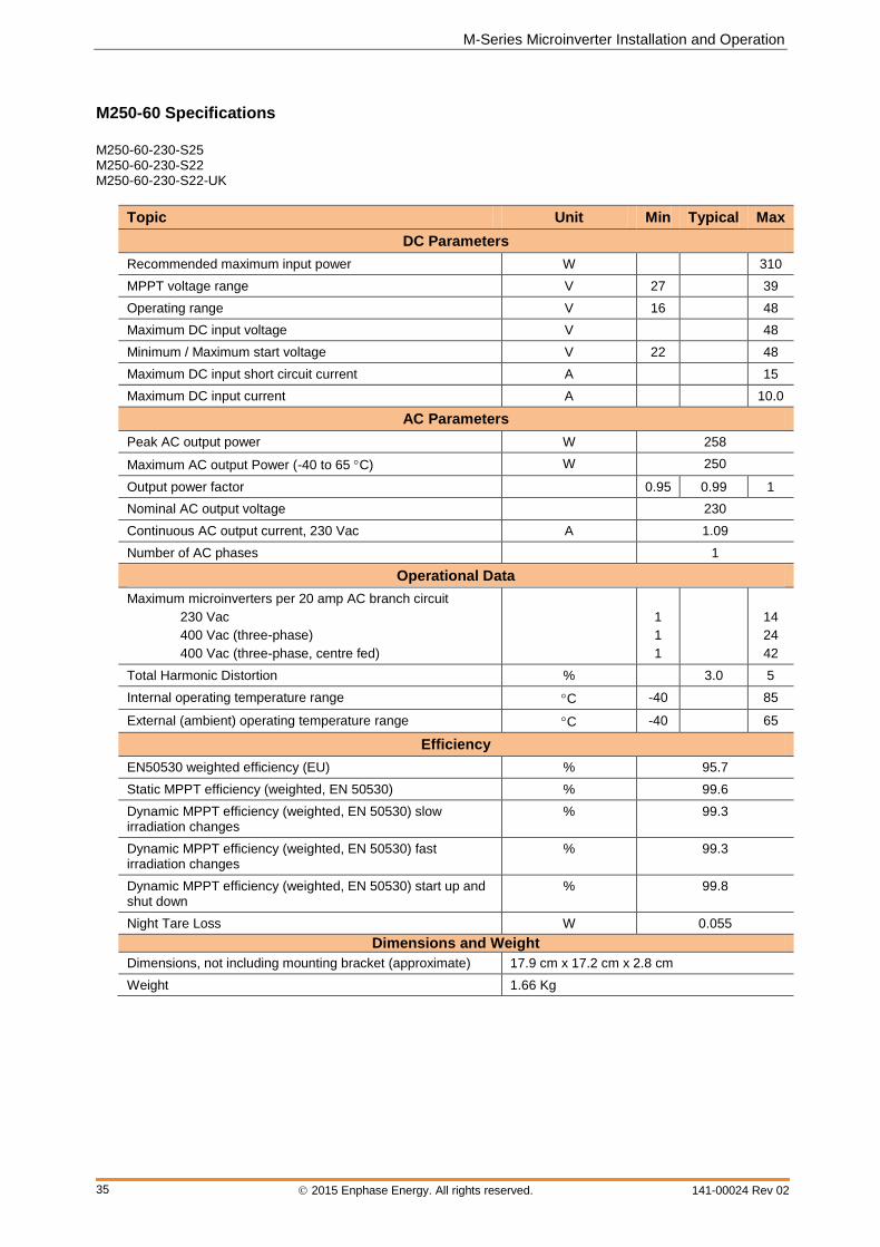
M-Series Microinverter Installation and Operation
2015 Enphase Energy. All rights reserved. 141-00024 Rev 02
35
M250-60 Specifications
M250-60-230-S25 M250-60-230-S22 M250-60-230-S22-UK
Topic Unit Min Typical Max
DC Parameters
Recommended maximum input power W 310
MPPT voltage range V 27 39
Operating range V 16 48
Maximum DC input voltage V 48
Minimum / Maximum start voltage V 22 48
Maximum DC input short circuit current A 15
Maximum DC input current A 10.0
AC Parameters
Peak AC output power W 258
Maximum AC output Power (-40 to 65 C) W 250
Output power factor 0.95 0.99 1
Nominal AC output voltage 230
Continuous AC output current, 230 Vac A 1.09
Number of AC phases 1
Operational Data
Maximum microinverters per 20 amp AC branch circuit
230 Vac
400 Vac (three-phase)
400 Vac (three-phase, centre fed)
1
1
1
14
24
42
Total Harmonic Distortion % 3.0 5
Internal operating temperature range C -40 85
External (ambient) operating temperature range C -40 65
Efficiency
EN50530 weighted efficiency (EU) % 95.7
Static MPPT efficiency (weighted, EN 50530) % 99.6
Dynamic MPPT efficiency (weighted, EN 50530) slow irradiation changes
% 99.3
Dynamic MPPT efficiency (weighted, EN 50530) fast irradiation changes
% 99.3
Dynamic MPPT efficiency (weighted, EN 50530) start up and shut down
% 99.8
Night Tare Loss W 0.055
Dimensions and Weight
Dimensions, not including mounting bracket (approximate) 17.9 cm x 17.2 cm x 2.8 cm
Weight 1.66 Kg
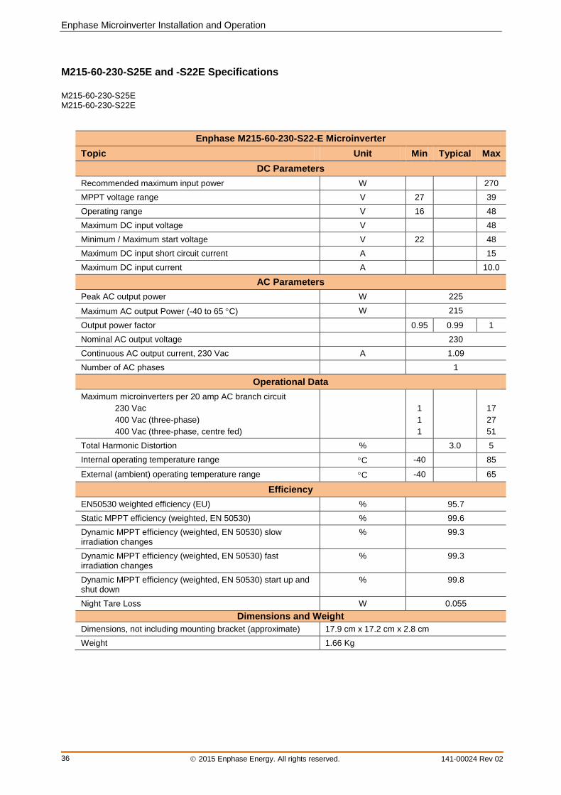
Enphase Microinverter Installation and Operation
2015 Enphase Energy. All rights reserved. 141-00024 Rev 02
36
M215-60-230-S25E and -S22E Specifications
M215-60-230-S25E M215-60-230-S22E
Enphase M215-60-230-S22-E Microinverter
Topic Unit Min Typical Max
DC Parameters
Recommended maximum input power W 270
MPPT voltage range V 27 39
Operating range V 16 48
Maximum DC input voltage V 48
Minimum / Maximum start voltage V 22 48
Maximum DC input short circuit current A 15
Maximum DC input current A 10.0
AC Parameters
Peak AC output power W 225
Maximum AC output Power (-40 to 65 C) W 215
Output power factor 0.95 0.99 1
Nominal AC output voltage 230
Continuous AC output current, 230 Vac A 1.09
Number of AC phases 1
Operational Data
Maximum microinverters per 20 amp AC branch circuit
230 Vac
400 Vac (three-phase)
400 Vac (three-phase, centre fed)
1
1
1
17
27
51
Total Harmonic Distortion % 3.0 5
Internal operating temperature range C -40 85
External (ambient) operating temperature range C -40 65
Efficiency
EN50530 weighted efficiency (EU) % 95.7
Static MPPT efficiency (weighted, EN 50530) % 99.6
Dynamic MPPT efficiency (weighted, EN 50530) slow irradiation changes
% 99.3
Dynamic MPPT efficiency (weighted, EN 50530) fast irradiation changes
% 99.3
Dynamic MPPT efficiency (weighted, EN 50530) start up and shut down
% 99.8
Night Tare Loss W 0.055
Dimensions and Weight
Dimensions, not including mounting bracket (approximate) 17.9 cm x 17.2 cm x 2.8 cm
Weight 1.66 Kg
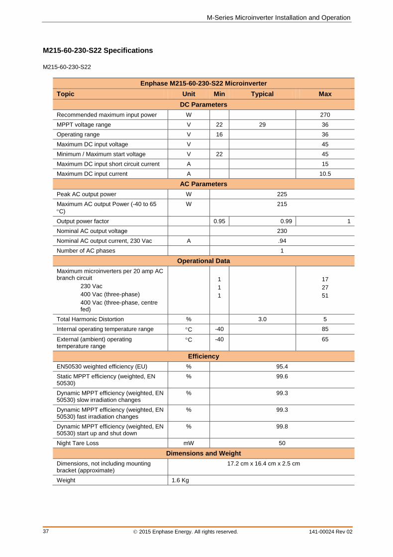
M-Series Microinverter Installation and Operation
2015 Enphase Energy. All rights reserved. 141-00024 Rev 02
37
M215-60-230-S22 Specifications
M215-60-230-S22
Enphase M215-60-230-S22 Microinverter
Topic Unit Min Typical Max
DC Parameters
Recommended maximum input power W 270
MPPT voltage range V 22 29 36
Operating range V 16 36
Maximum DC input voltage V 45
Minimum / Maximum start voltage V 22 45
Maximum DC input short circuit current A 15
Maximum DC input current A 10.5
AC Parameters
Peak AC output power W 225
Maximum AC output Power (-40 to 65
C)
W 215
Output power factor 0.95 0.99 1
Nominal AC output voltage 230
Nominal AC output current, 230 Vac A .94
Number of AC phases 1
Operational Data
Maximum microinverters per 20 amp AC branch circuit
230 Vac
400 Vac (three-phase)
400 Vac (three-phase, centre fed)
1
1
1
17
27
51
Total Harmonic Distortion % 3.0 5
Internal operating temperature range C -40 85
External (ambient) operating temperature range
C -40 65
Efficiency
EN50530 weighted efficiency (EU) % 95.4
Static MPPT efficiency (weighted, EN 50530)
% 99.6
Dynamic MPPT efficiency (weighted, EN 50530) slow irradiation changes
% 99.3
Dynamic MPPT efficiency (weighted, EN 50530) fast irradiation changes
% 99.3
Dynamic MPPT efficiency (weighted, EN 50530) start up and shut down
% 99.8
Night Tare Loss mW 50
Dimensions and Weight
Dimensions, not including mounting bracket (approximate)
17.2 cm x 16.4 cm x 2.5 cm
Weight 1.6 Kg
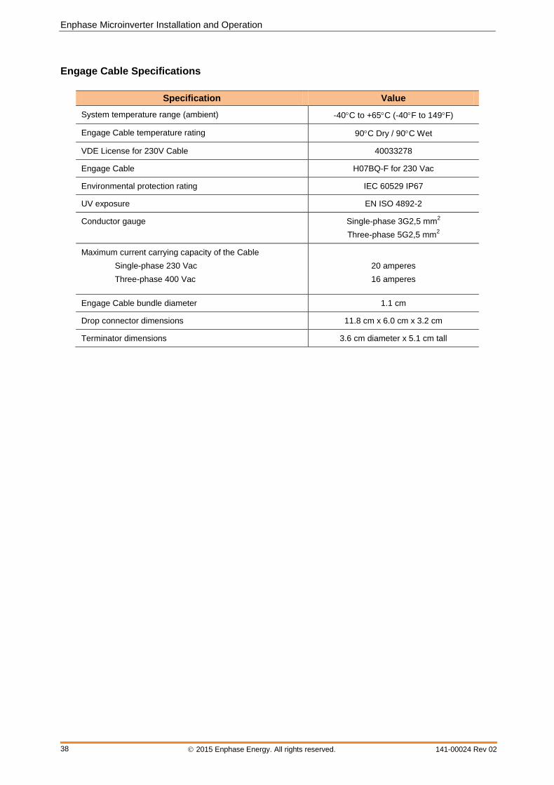
Enphase Microinverter Installation and Operation
2015 Enphase Energy. All rights reserved. 141-00024 Rev 02
38
Engage Cable Specifications
Specification Value
System temperature range (ambient) -40C to +65C (-40F to 149F)
Engage Cable temperature rating 90C Dry / 90C Wet
VDE License for 230V Cable 40033278
Engage Cable H07BQ-F for 230 Vac
Environmental protection rating IEC 60529 IP67
UV exposure EN ISO 4892-2
Conductor gauge Single-phase 3G2,5 mm2
Three-phase 5G2,5 mm2
Maximum current carrying capacity of the Cable
Single-phase 230 Vac
Three-phase 400 Vac
20 amperes
16 amperes
Engage Cable bundle diameter 1.1 cm
Drop connector dimensions 11.8 cm x 6.0 cm x 3.2 cm
Terminator dimensions 3.6 cm diameter x 5.1 cm tall
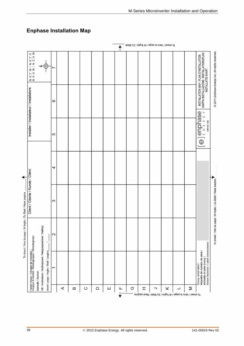
M-Series Microinverter Installation and Operation
2015 Enphase Energy. All rights reserved. 141-00024 Rev 02
39
Enphase Installation Map
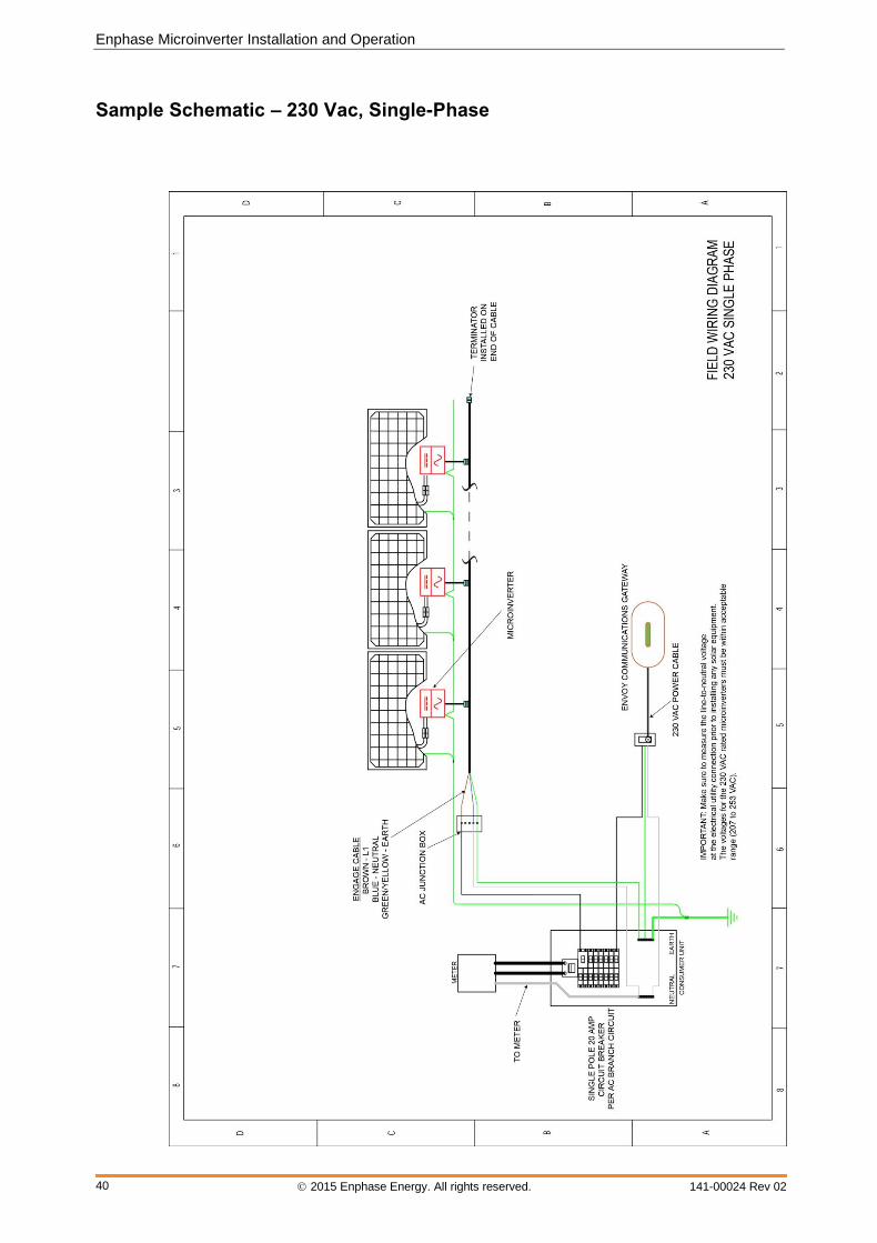
Enphase Microinverter Installation and Operation
2015 Enphase Energy. All rights reserved. 141-00024 Rev 02
40
Sample Schematic – 230 Vac, Single-Phase
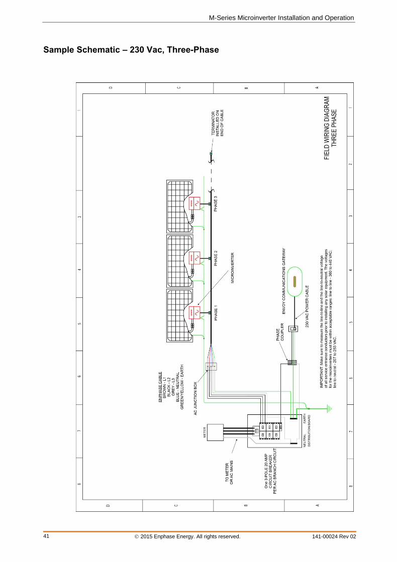
M-Series Microinverter Installation and Operation
2015 Enphase Energy. All rights reserved. 141-00024 Rev 02
41
Sample Schematic – 230 Vac, Three-Phase

Enphase Microinverter Installation and Operation
Corporate Headquarters Contact Information
Enphase Energy Inc. 1420 N. McDowell Blvd.
Petaluma, CA 94954 USA
http://www.enphase.com [email protected]