m series pump models m6 and m50 instruction manual · models m6 and m50 instruction manual ......
TRANSCRIPT

Valco Instruments Co. Inc.
m6-m50.MForce.indd Rev. 9/17
M Series Pump Models M6 and M50 Instruction Manual
For units with MForce controller, shipped since September 2016
Valco Instruments Co. Inc.800 · 367· 8424 sales 713 · 688· 9345 tech 713 · 688· 8106 fax [email protected]
VICI AG InternationalSchenkon, Switzerland Int + 41 · 41 · 925· 6200 phone Int + 41 · 41 · 925· 6201 fax [email protected]
North America, South America, and Australia/Oceania contact: Europe, Asia, and Africa contact:® ®

The information in this manual has been carefully checked and believed to be accurate; however, no responsibility is assumed for inaccuracies.
VICI maintains the right to make changes without further notice to products described in this manual to improve reliability, function, or design. VICI does not assume any liability arising from the use or application of this product; neither does it convey any license under its patent rights.
MForce is a trademark of Schneider Electric Motion USA.
Certain copyrighted figures and diagrams used in this manual are used with the permission of Schneider Electric Motion USA.
VICI does not recommend the use of an M Series pump in life support or applications where it may directly or indirectly threaten life or injury. See the Warranty and Disclaimer statement included in the back of this manual.

Table of ContentsProduct Description Operating Principle..........................................................................................1 Software ..........................................................................................................1
Getting Started Components of the M Series System .............................................................2 PC System Requirements ...............................................................................2
Hardware Installation Mounting .........................................................................................................4 Connections ....................................................................................................5
Initial Setup MSLHS Software Installation ..........................................................................7 COM Port Assignment ....................................................................................7 Initialization .....................................................................................................7 Selecting Pump and Gearbox Values ..............................................................8 Setting the Backlash and Volume/Revolution Values ......................................8
Priming and Testing the Pump Tubing Connections (M6 shown) ...................................................................10 Initial Priming ................................................................................................10
Programming Application Methods Method Screen Functions .............................................................................12 Example Application Methods 1. Prime System ...................................................................................14 2. Aspirate and Dispense .....................................................................14 3. Dispense Selected Reagents ...........................................................16
Maintenance Routine Maintenance ....................................................................................17 Routine Cleaning...........................................................................................17
Chemical Compatibility of Wetted Surfaces Model M6 ......................................................................................................18 Model M50 ....................................................................................................19
Technical Support ................................................................................................20
Returning Pumps for Repair ................................................................................20
Operational and Technical Specifications ............................................................21
Appendix A: MForce Terminal Section Terminal Programming Mode ........................................................................22
Appendix B: Setup for Multipump Operation Connections ..................................................................................................24 Data Cable Termination Resistors .................................................................24 Setting the Address of each MForce Controller ............................................25 Troubleshooting Party Mode Communications ..............................................26
Warranty ..............................................................................................................27

This page intentionally left blank for printing purposes

1
Product DescriptionThe Cheminert® M Series liquid handling pump is a syringe-free pump capable of delivering a bidirectional flow to six orders of magnitude. It is a positive displacement pump, which means that it is self-priming and tolerant of any gas which may find its way into the fluid lines. Since there is no separate fill cycle, the pump can be operated continuously, and volumetric capacity is limited only by time.
RS-422/485 communication protocols are incorporated into the micropro-cessor-driven controller. USB interface requires an adapter cable, supplied as part of the full pump package.
The M Series pump is recommended for any liquid handling applications re-quiring accuracy and precision. It is particularly suited for applications with a wide range of volumes (which entail laborious syringe changes with other pumps) and for applications which benefit from the versatility provided when the pump is coupled with the optional multiposition reagent selection valve.
Operating PrincipleAt the core of the pump is a rotor which houses four pistons. As the micro-stepper motor turns the rotor, the pistons float on a stationary cam; at any given moment, one piston is filling, one is dispensing, and the other two are in transit between the fill and dispense positions.
SoftwareThe pump comes complete with MSLHS software, which employs standard liquid handling terminology and an integrated valve control package in a familiar Windows format for everyday lab usage. For more advanced control of system parameters, download a programming manual directly from the manufacturer at http://motion.schneider-electric.com/downloads/manuals/MCode.pdf.
Hardware installation (pages 4-6) is the same for all users.

2
Getting Started
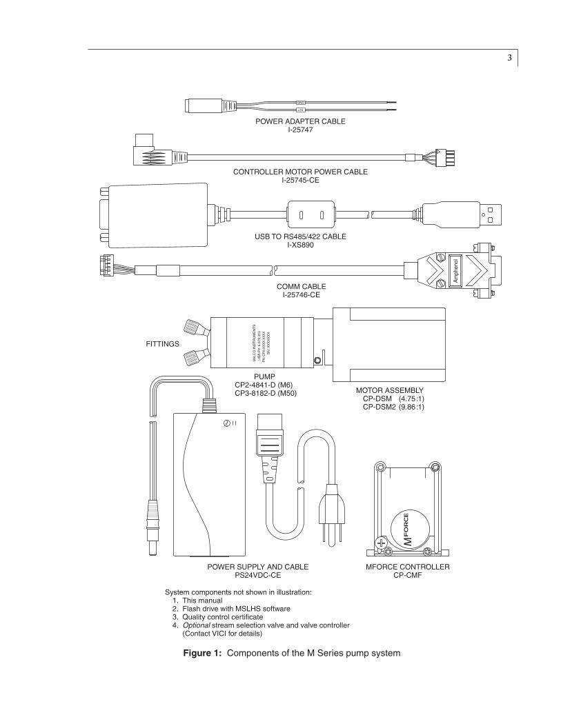
Components of the M Series Pump SystemCheck the contents of the packages against Figure 1 to verify that you have received all of the components. Contact the factory if anything is missing or damaged. (NOTE: damaged shipments must remain with the original packaging for freight company inspection.)
Components include:
•Pump ModelM6: ProductnumberCP2-4841-D ModelM50: ProductnumberCP3-8182-D
•Motorassembly ModelM6: ProductnumberCP-DSM ModelM50: ProductnumberCP-DSM2
•MForcecontroller:ProductnumberCP-CMF
•Poweradaptercable:ProductnumberI-25747
•Controllermotorpowercablewith5pinDINconnector: ProductnumberI-25745-CE
•Commcable:ProductnumberI-25746-CE
•RS-422/485toUSBconvertercable:ProductnumberI-XS890
•24VDCpowersupplywith110/220VACcable: ProductnumberPS24VDC-CE
•Fittings(2) ModelM6: ProductnumbersZN1FPK(nut)andZGF1PK(ferrule) ModelM50: ProductnumbersCFL-2BK-S(nut)and CFL-CB2KF-S(bushing)
•MSLHSsoftware(flashdrive)
•Manual
•Qualitycontrolcertificate
PC System Requirements PentiumPC100MHzorhigher,runningWindows95,98,ME,NT,2000, XP,7,or10.Thepumpcontrollerrequiresadedicatedserialport.Ifyourpumpsystemincludesavalvewithelectricactuator,anadditionalserialportisrequired.
3
Figure 1: Components of the M Series pump system
���
���
������������������������� ������������������ ������������ ����������� �������������� ���� ��������������������������� �������������������������������������������������
����������������������
�����������������������������������
�������������������������
����������������������������
�����������������������������
�������������������
������������������� ��������������� ���������
�������������� ������������� ����
��������
����
����
�����
���
�����
����
����
����
���
����
�����
����
�����
������
��
����
��
�����������������

4
Hardware Installation
MountingThe mounting points of the pump motor and controller are given in Figure 2, along with the external dimensions of each module.
For best results, the M Series pump must be oriented with its ports facing up. If the pump is oriented in any other direction, bubbles may be trapped in the internal chambers of the pump.
The controller should be mounted in such a way to allow adequate cooling.
Figure 2: Mounting points and external dimensions for the pump, motor, and controller
�����������������������
���������
��� ������������������������������
�������������
�������������
�������������
���������������
�������������
�������������
�������������
��������������
�������������
�������������
�������������
��������������
���������
�������� ���
�������
��� �������������������������������
�������������
��������������
��������������
���������������
��������������
��������������
��������������
5
Connections
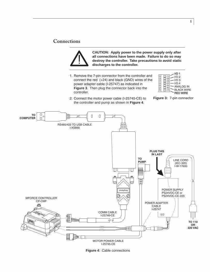
CAUTION: Apply power to the power supply only after all connections have been made. Failure to do so may destroy the controller. Take precautions to avoid static discharges to the controller.
1. Removethe7-pinconnectorfromthecontrollerandconnectthered(+24)andblack(GND)wiresofthepoweradaptercable(I-25747)asindicatedin Figure 3. Then plug the connector back into the controller.
2. Connectthemotorpowercable(I-25745-CE)to the controller and pump as shown in Figure 4.
Figure 3:7-pinconnector
Figure 4: Cable connections
���
���
����������������
����������������� ��������
������
����������
� ������� ������� �������
��������
�����
���������������������������������������
������������������ ����
���������������������� ���� �
�������
���������� ��������
�����������������������
���������������������
��������
�����
��������
��������������������� ������ ��������
6
3. Connectthemale9-pinconnectoroftheI-XS890USBadaptercabletothefemale9-pinconnectorofthecommcable(I-25746-CE),thenplugthe USB connector into the computer. Or, if you prefer, a custom comm cable can be fabricated using the connector included with the USB adapter cable.
4. Plugthe10-pinfemaleconnectorofthecommcable(I-25746-CE)intothe MForce controller.
5. Plugthepowersupplyintothepoweradaptercable(I-25747).
6. Plugthelinecord(I-W-17600)intoa110or220VACsource.
7. Finally,connectthelinecordtothepowersupply.(Thissequenceisrecommended by the manufacturer of the MForce controller.)
8. Ifthesystemincludesavalve,plugoneendofitsRS-232cableintothe valve actuator controller and the other end into a serial port on the computer.Ifaserialportisnotavailable,anRS-232toUSBadapterisrequired.
For more advanced hardware and connectivity options, download a Motion Control MForce hardware manual directly from the manufacturer at http://motion.schneider-electric.com/downloads/manuals/MFI.pdf.
Hardware Installation

7
Initial Setup
MSLHS Software InstallationInserttheflashdrivewiththeMSLHSsoftwareintothePC.Iftheinstallationdoesn’t begin automatically, browse the drive and double click on the file called setup.exe. The installer will place an icon for MSLHS on the Windows desktop.
COM Port Assignment1. DoubleclicktheicononthedesktoptostarttheMSLHSsoftware.
2. On main menu, choose Utility > Setup, as in Figure 5.
3. SelectthecorrectCOMportforthepumpandvalve. If no valve is being used, select None. (Figure 6)
4. Click Apply, then Close.
Figure 5: Select “Setup”
Initialization1. Onthemainmenu,chooseUtility>InitializePump.Ifinitializationis
successful, proceed to the next section, “Setting the Backlash and Volume/RevolutionValues”.
2. If the error message in Figure 7 appears, close the window, then check to make sure that all the connectors are completely pluggedin.RepeatStep1.
3. Ifinitializationissuccessful,proceed to the next section, “Setting the Backlash and Volume/RevolutionValues”.
4. If the error message persists, make sure that the COM port assignments correspond to the ports to which the cables are physically connected. RepeatStep1.
Figure 6: Select COM ports for pump and valve
ASSIGNCOMPORTVALUESFORPUMPANDVALVE
Figure 7:Initializationerrormessage

8Initial Setup
Selecting Pump and Gearbox ValuesIntheGearboxpulldownmenu,selectCP-DSM1orCP-DSM2,basedonthegearboxtypeindicatedonthemotorlabel.IfthelabelsaysCP-DSM,selectCP-DSM1.
InthePumppulldownmenu,select100forModelM6or628forModelM50.(Thevalues4and750arecurrentlyunused.)Thesevaluesrepresentnominal µL/revolution for the two models. The next section discusses how these can be overridden for greater accuracy.
Setting the Backlash and Volume/Revolution ValuesBacklash is defined as the transition from the aspirate function to the dispense function, or vice versa. The MSLHS software observes the factorydefaultsettingsof1.5µLforbacklashand100µLor628µLfor volume/revolution (as set above, depending on the pump model).
However, the actual values for each pump are calibrated and recorded on theQCcertificatesuppliedwitheveryunit.Forthehighestaccuracyandprecision, these values should be entered manually.
To override the factory default values for backlash and µL/rev:
1. LocatethebacklashandµL/revvaluesontheQCcertificate.
2. Click the Enable box under Backlash on the Setup screen, and type in the backlash value, as indicated in Figure 9 on the page opposite.
3. ClicktheUsemeasureduL/revboxunderPump,andtypeinthevolumeper revolution.
4. Click Apply, then Close.
SELECT100FORMODELM6OR628FORMODELM50
SELECTCP-DSM1ORCP-DSM2, ASINDICATEDONTHEMOTORLABEL. (If it says CP-DSM, select CP-DSM1.)
Figure 8: Selecting pump and gearbox values

9
Figure 9: Setting the backlash and volume per revolution values
CLICKTHEBOXANDENTERTHE µL/REVFROMTHEQCCERTIFICATE
CLICKTHEBOXANDENTERTHEBACKLASHVALUEFROMTHE QCCERTIFICATE
Initial Setup

10
��������������
�����
���� ��� �������
Priming and Testing the PumpAt this stage, some basic tests will determine that the tubing connections are tight and that the pump is rotating in the proper direction. The tests include an initial priming of the pump to remove all air and unwanted solutions in the tubing.
Use proper safety precautions when pumping flammable liquids. In all applications, make sure you have enough tubing and sufficient quantities of solutions ready for use before beginning a procedure.
Tubing Connections (M6 shown)M6pumpsshouldnotbeusedwithtubingODssmallerthan1/16".ForM50pumps,theminimumODis1/8".
Improperly installed fittings can create space for a bubble to become trapped, degrading pump performance. The use of non-VICI fittings can also adversely affect pump function and performance.
1. Connectalengthoftubingtotheinlet(PortA)andplacetheotherendina vessel containing isopropyl alcohol.
2. Connectasecondlengthoftubingtotheoutlet(PortB)andplacetheother end into a receiver bottle.
Fitting Assembly Instructions1. Slidethenutandferruleonto
the tubing in the order shown.
2. Insert this assembly into the fitting detail, screwing the nut in two or three turns by hand.
3. Pushthetubingallthewayforwardintothedetailsothatitseatsfirmly.This is essential for a proper zero dead volume connection.
4. Turn the nut into the detail until it is finger tight.
Initial PrimingIn the Test Mode, a mouse click on a button directs the pump to either aspirate or dispense. (Refer to page 13, No. 7 for a definition, if required.) WhentheEnableboxintheFixedVolumeareaischecked,(seeFigure 8) thepumpwillaspirateordispensethequantityenteredintheFixedVolumefield and then stop. If the Enable box is not selected, the pump will continue to run at the set Flow Rate until either Stop (stops aspirating or dispensing) orQuit(exitstheTestMode)isselected.
If the pump aspirates a volume larger than the outlet tube volume, sample or reagent could enter the pump and mix with liquid in the reservoir.

11
1. IfthescreeninFigure 10 is not already open, go to the main menu, and choose Utility > Test.
2. IfthetubingIDis0.010”orless,enter FlowRate: 200µL/min FixedVolume: 1000µL Click the Enable box
IfthetubingIDislargerthan0.010”,enter FlowRate: 9000µL/min FixedVolume: 1000µL Click the Enable box
(In the Test Mode, user-entered flow parameters cannot be saved; when you exit the program, these values will revert to defaults.)
NOTE:SmallerIDandlongerlengthtubingcancauseexcessiverestriction. Adjust flow rates accordingly. Maximum backpressure is100psi.
3. ClicktheDispensebutton.Thedesignatedvolumeofisopropylalcoholshould move through the tubing and into the receiver bottle, removing any air bubbles and priming the system. If it does, the pump is primed and ready for use.
NOTE: If a buffer will be used, flush all the isopropyl alcohol out of the lines by placing the inlet tube in a vessel of water, changing the fixedvolumeto2000µL,andclickingtheDispensebutton.
4. If the pump doesn’t seem to draw any isopropyl alcohol into the tubing: (a) Check for leaks around the fittings and make sure the tubing is well seated in the pump head. (b) Make sure the end of the tubing is free to draw liquid into the pump. (TIP:Cutthetipendthatgoesintotheisopropyl alcohol reservoir at a 45° angle.)
(c) Touch the pump to make sure it is on.
If the pump still doesn’t seem to function properly, consult the factory.
Figure 10:PrimingthepumpintheTestMode(M6valuesshown)
CLICKTHEBOX FOR A ONE TIME FIXEDVOLUMEASPIRATEOR DISPENSE.
LEAVETHEBOX UNCLICKEDFORCONTINUOUS PUMPINGATTHEENTEREDFLOWRATE.

12
� � � � �
�
�� �� �� ��
��
� � � �� ��
��
��
��
Figure 11: The Method screen
Programming Application MethodsMethod Screen Functions
From the main menu, choose Method > New to open the screen below.
1: Method status Idle, Active (running), or Editing
2: Mode activation buttons Run: Starts running the method. Reset: Pausesamethodwhichisunderway,allowingachangetothe editing mode. Repeat: If this box is clicked, when the method completes the last action, it goes back to first action in a continuous loop.
3: Function status Indicates the current activity during a run.
4: Event button Refer to No. 11: Event box.
5: Edit and Close buttons Edit: When the method is idled, clicking this button changes it into the editing mode. Close: Closes the method screen.

13
6: Action line A step in the method sequence, reflecting the values entered by selecting ortypingvaluesinthePump,Valve,andWaitfields.Tomovetoadiffer-ent line for editing, just click on it or use No. 12: Up and Dn buttons.
7: Pump function Aspirate: Drawliquidinto the line connected to the pump outlet(PortB). Dispense: Force a pre-programmed amount of liquid through the pump. Wash: Wash or flush the lines (always in the outward direction, or A to B) with system fluid or a pre-programmed reagent selected.
8: Volume The amount to be aspirated, dispensed, or sent through as a wash.
9: Flow rate The rate at which the given volume is aspirated, dispensed, or sent through as a wash.
10: Wait field If a value is entered in this field for an action line, during a run the program will wait for the designated time (in seconds) after the completion of that action before advancing to the next action. Used after an aspirate or dispense step to allow the liquid to equilibrate in the line or the dispensed liquid to come to equilibrium, as with viscous liquids or very small capillary tubing.
11: Event box When this box is clicked when programming an action line, the program will stop before that action is executed. The program will remain stopped until No. 4: Event Button is clicked. (If the step before the event line has a programmed Wait interval, the Event button will not trigger the action until the Wait interval has elapsed.)
12: Up and D(ow)n buttons In the Editing mode, these move the line highlighter up and down.
13: Valve type Multi-Pos: Multipositionstreamselector 2-Pos: Two position switching valve/injector
14: Valve Position The position the valve needs to be in to select the proper solvent or reagent.
15: Valve Direction(forMulti-Posonly) The direction the valve will take to the indicated position – the shortest (used in most cases), clockwise, or counterclockwise.
16: Insert button Inserts a new action line above the highlighted line.
17: Duplicate button Duplicatesthehighlightedline.Thenewlinecanthenbeeditedasrequired.
18: Delete button Deletesthehighlightedline.
19: End Edit button When editing is complete, click this button to return to the Idle mode, ready to Run.

14
Example Application MethodsIn the Test Mode, user-entered flow parameters cannot be saved; when you exit the software, the values revert to defaults. So creating several simple example methods is a useful way to start learning the M6-LHS software. ThemethodsbelowutilizeflowparameterscharacteristicoftheModelM6,butthesameprinciplesapplytoprogrammingfortheM50.
Example method 1: “Prime System”1. Fromthemainmenu,chooseMethod>Newtoopenthescreenin
Figure 11onpage12.
2. Action line one will be highlighted. In the pump function field, select Dispense,andenterthevolumeandflowratevaluesfromStep2atthetopofpage11.Thiswilldispensetheisopropylalcohol,asinourinitialpriming done in the Test mode.
3. ClickDuplicatetoaddanew,identicalaction.
4. While action line 2 is highlighted, check the Event box.
5. Click the End Edit button.
6. On the main menu, choose Method > Save, and call this method “prime system”.
Running “prime system”
1. Withtheinlettubeinavesselofisopropylalcohol,clicktheRunbutton.TheboxnexttoDispenseinthefunctionstatusareawillturngreen,indi-cating that the first action line is underway.
Since the Event box for action line 2 is checked, the program will pause before executing action line 2.
2. Move the inlet tube to a vessel of water and click on the Event button to start action line 2, which now dispenses water to flush the alcohol from the system.
Example method 2: “Aspirate and Dispense”1. Fromthemainmenu,chooseMethod>Newtoopenthescreenin
Figure 11onpage12.
2. Action line one will be highlighted. In the pump function field, select Wash,thenenter1000forthevolumeand9000fortheflowrate.Forlarger tubing, increase the wash volume to equal five times the tubing volume.
3. ClicktheDuplicatebuttontomakeanidenticalWashactionline.
4. UsetheDn(down)buttontohighlightthesecondline,thenclicktheInsert button.
5. For the newly inserted line, select Aspirate in the pump function field, thenenter10forthevolumeand100fortheflowrate.
6. ClicktheDuplicatebuttontomakeanidenticalAspirateline.
7. Clickonthenewlycreatedlinetohighlightit,thenchangethevolumeto100andtheflowrateto500,andenter“2”intheWaitbox.
Programming Application Methods
15
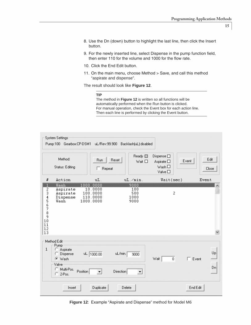
8. UsetheDn(down)buttontohighlightthelastline,thenclicktheInsertbutton.
9. Forthenewlyinsertedline,selectDispenseinthepumpfunctionfield,thenenter110forthevolumeand1000fortheflowrate.
10. ClicktheEndEditbutton.
11. Onthemainmenu,chooseMethod>Save,andcallthismethod “aspirate and dispense”.
The result should look like Figure 12.
TIP The method in Figure 12 is written so all functions will be automatically performed when the Run button is clicked. For manual operation, check the Event box for each action line. Then each line is performed by clicking the Event button.
Figure 12:Example“AspirateandDispense” method for Model M6
Programming Application Methods

16
Figure 13:Methodscreen(partial)forexample“DispenseSelectedReagents” method for Model M6
Example method 3: “Dispense Selected Reagents”This method, which employs an 8-position multiposition valve for selecting multiple reagents to be added to tubes or microplates, is a typical example oftheapplicationspossiblewhenaValcoorCheminertvalveisintegratedinto the pump/M6-LHS system. A wash step (or in this case, a prime step) is incorporated between reagents.
NOTE: Wash is always in the dispense or outward direction of the pump, and can be used for washing with a system fluid, or, as in this case, a reagent.
By now you should know how to enter all the information shown in Figure 13 to create this method. (Only the first four positions for the 8-position valve are shown.)
TIP YoumightfindithandytousetheDuplicatebuttontocreateallthenearlyidenticalMultiValveactionlines,thengobackwiththeInsertbuttontocreatetheWashandDispenselines.
Programming Application Methods

17
Maintenance Follow these recommended cleaning and maintenance instructions to obtain optimum performance and maximum life from your pump.
If the pump is not going to be used for at least 24 hours, make sure no solvents are left in the pump. Following this procedure will extend pump lifetime and prevent seizing.
Routine maintenance• Flushthepumpthoroughlywithdistilledorde-ionizedwateraftereachuse.
Store the pump dry.
• Avoidrunningthepumpdryforextendedperiods.Thepumpisself-priming and will dispel entrapped bubbles when orientated vertically.
• Inspectthepumpforsignsofleakageonaregularbasisandcorrectanyproblems immediately. Liquid entering the motor housing could damage the motor and gear assembly.
Leakage from the pump’s leak port indicates excessive backpressure and unreliable pumping action. (See Figure 2 on page 4.)
• Wipeupallspillsonandaroundthepumpimmediately
Routine cleaningThe high temperatures associated with autoclaving will compromise the pump seals. Therefore, chemical procedures should be employed to ensure sterility. The pump fluid path can be cleaned with any of the following cleaning solutions:
• Dilutedetergentwash
• Diluteacidandbasewash Pump5mLof0.1N NaOH, followed by 5 mL (Model M6) or50mL(ModelM50)ofwater, followed by 5 mL of 0.1N HCl, followed by 10mL(ModelM6)or50mL(ModelM50)ofwater
• Dilutebleachwash: Pump5mLofa10% bleach solution followed by 10mL(ModelM6)or50mL(ModelM50)ofwater

18
Chemical Compatibility of Wetted Surfaces
To ensure best results, please consider the chemical compatibility of the wetted surfaces with the liquids to be used before putting the pump into service.
Model M6 (standard)PTFEThepistontipsaremadefromPTFE.Polytetrafluoroethyleneisthegenericname for the class of materials such as Teflon®. It offers superior chemical resistance and lends itself to good sealing characteristics. Because it’s so easy to handle, it is often used in low pressure situations such as the M6 pump.CompoundsoflowmolecularweightcanpermeatePTFE.
PAEKThepumpportendcapismadeofaPAEK-basedcomposite. Polyaryletherketoneisthegenericnameforthefamilyofpolyketonecom-pounds.PAEKincludesPEK,PEEK,PEKK,andPEKEKK,whichdifferinphysical properties and, to a lesser degree, in inertness. This composite usedintheM6resistsallcommonHPLCsolventsanddiluteacidsandbases. However, concentrated or prolonged use of halogenated solvents may cause the polymer to swell. Avoid concentrated sulfuric or nitric acids (over10%)andrefertotheguidelinesonthenextpage.
Valcon PTheM6pumprotorismadefromValconP.ThisPTFE/carboncompositeisemployedasarotormaterialinmanyValcovalves,soithasseenextensiveuseinmanyanalyticalapplications.Itisroutinelyusedat1000psi/75°C,andcanalsobeusedattemperaturesapproaching200°Cwithdecreasedsealing tension.
SapphireThe M6 piston chambers are made of sapphire and are sealed in place withaViton® O-ring. Sapphire has a unique set of properties including high strength, hardness, surface smoothness, and excellent chemical compatibility. It is commonly used in applications where a combination of exceptional mechanical and chemical properties is essential.
Viton®
Viton® O-rings are used to seal the sapphire pistons. Besides its excellent mechanicalproperties,Viton® provides the best proven fluid and chemical resistance of any commercial non-fluorinated elastomer. NOTE: Viton® is not compatible with THF and acetone. Use of these substances will cause premature O-ring failure, which can lead to additional pump damage.
Teflon®isaregisteredtrademarkofE.I.duPontdeNemours. Viton®isaregisteredtrademarkofDuPontDowElastomers.

19
Model M50 (standard)Valcon H2TheM50capisacarbonfiber-reinforced,PTFE-lubricatedinertpolymer.Thismaterialisroutinelyusedat5000psiattemperaturesnotmorethan75°C.
CeramicTheM50pumprotorismadeofceramic(ZrO2), which is resistant to most chemicals.
PTFEThepistontipsaremadefromPTFE.Polytetrafluoroethyleneisthegenericname for the class of materials such as Teflon®. It offers superior chemical resistance and lends itself to good sealing characteristics. Because it’s so easytohandle,itisoftenusedinlowpressuresituationssuchastheM50pump.CompoundsoflowmolecularweightcanpermeatePTFE.
GuidelinesSpecific reagent combinations should be tested to insure compatibility with pump components. Since the least chemically inert component in these compositesisPEEK,foroptimumcomponentlifetimethefollowingguide-lines*(forPEEKatroomtemperature)shouldbefollowed:
Acids and bases ...................Nostrongerthan1M(exceptionsnotedbelow) Sulfuric acid ..........................Resistantto10% Hydrochloric acid ..................Resistantto20% Hydrofluoric acid ...................Notresistantto40%(nodataonlowerconc.) Nitric acid ..............................Resistantto10% DibutylamineinToluene ........Not rated Sodium hydroxide .................Resistant Hydrogen sulfide ...................Resistant Methyl mercaptan .................Not rated Acetone ................................Resistant(seeViton® note on previous page) Methyl ethyl ketone ...............Resistant Methyl alcohol .......................Resistant Toluene .................................Resistant Xylene ...................................Resistant Chloroform ............................Resistant Chlorobenzene .....................Resistant Iodine/iodide in water ............Not rated Sodium hypochlorite .............Resistant (household bleach) Permanganate ......................Resistant Hexane .................................Resistant
* CorrosionResistanceTables,Schweitzer,MarcelDekker,1991
20
Technical SupportTechnicalsupportforthisproductishandledbytheVICIfacilitiesinHouston,Texas,USA,andSchenkon,Switzerland.
USA Switzerland Telephone: (713)688-9345 Telephone: int+4141925-6200 Fax: (713)688-8106 Fax: int+4141925-6201 Email: [email protected] Email: [email protected]
Firmware updates for the MForce can be downloaded from www.IMSHome.com.
Returning Pumps for RepairThefollowingproceduremustbefollowedwhenpumpsarereturnedtoVICI for repair:
1. ToobtainaReturnMerchandiseAuthorizationnumber(RMA#),goto http://www.vici.com/returns.php. You can navigate there by clicking the Returns/repairs link under the Service pulldown menu.
2. Return the pump and the completed decontamination report (if requested) to: VICIValcoInstrumentsCo.Inc. RepairDepartment Attn:RMA# 8300Waterbury Houston,TX77055
or
VICIAGInternational Attn:RMA# Parkstrasse2 CH-6214Schenkon,Switzerland

21
Operational and Technical Specifications
�����������������������
���������� ������������ ������������������� �� ����� ����
����������������� ����� ���������������������� ������ ������ ������� �� ����� �����
���������� �������� ���������������� ��� ������� ������������������������� ��� ������� ���������������������������� ���� �������� ������������������� ������� ���� �� ���� ������������������������ ��������� �������������� �������������� ��������������� ������������
�������������� ��������������
�������� ������������������������������������������������
������������ ������� ����������� ������������������������������� ��������
��������������� �������
���� ����� ������
����
�� � ��������� ���������� ������ �
������������
� ���������� ������ ��������� ��������������� ������������������������������ ������ ������¡�����������
���������������������������
�� � ��������
������� �� ���������� ������������������������� ������ ¢����������� ���������� ���� ����� ��������������� ¢������� ���££
�����������������
���������������� ������ ������������������� �� ����������������
������ �� ������������� ���¤����������������
������������������� �
� �
�������� ��������������� ���������������� ��������������� ������������������������� ������������������������������������ �� ��� ������

22
Appendix A: MForce Terminal Section
Figure 15: MForce commands, part A
Terminal Programming ModeThe Terminal programming mode is for advanced control of the M Series Pump,allowingtheusertoalterthefactorydefaultsettingsforvarious parameters. While this may be useful in certain research applications, the main use is for OEM (original equipment manufacturer) customers. Figures 15 and 16showthevariouscontrolsettingsusedforspecializedapplications, as well as the default settings.
On the main menu, choose Utility > Terminal, as in Figure 14. To change any of the parameters, enter the commands in Figures 15 and 16.
Figure 14: Select “Terminal”
Command Function Default
A=n Set acceleration in steps/sec2 from91-1000000000. 1000000
AL UsedwiththePRinstructiontoprintthevalue/stateofallvariablesandflags to the terminal program.
BD=n SetcommunicationsBAUDrate,inbps: 48=4800 96=9600 19=19200 38=38400 11=115200
96
BY Busy flag (program executing). 0=noprogramrunning,1=programexecuting
CPn Clearprogramatthespecifiedaddress,from1-767.
D=n Set deceleration in steps/sec2 from91-1000000000. 1000000
DN=<"asciicharacter">
SetsthedeviceaddressforPARTYmodeoperation:0-9,A-Z,ora-z. !
E Stops the execution of a program. Used in program mode to designate the end of the program.
EF UsedwiththePRinstructiontoprintthestateoferrorflagstothetermi-nal program. 0=noerrorexists,1=errorconditionexists
EM=n Sets the full/half duplex configuration of the RS-485 channel. 0=fullduplex(allinfosentbackovercommline) 1=halfduplex(onlypromptsaresentback;infonotechoed) 2=onlyrespondstoPRandLcommands 3=savesechoinprintqueue,thenprintsaftercommandisterminated
0
ER UsedwiththePRinstructiontoprinttheerrorcodeforthemostrecenterror that has occurred.

23
We recommend that you contact VICI technical support before changing any of the factory default values. They are application dependent, and any changes could adversely affect the pump and its performance.
Command Function Default
EXa,n Execute program at a specified address or label (a) using selected mode (n=0,1,or2). 0(orblank)=normalexecution 1=tracemode The program executes continuously until the program E is encountered; the instructions are “traced” to the communications port so the user can see what instructions have been executed. 2=single step mode User can step through the program using the space bar to execute the next line of the program.
FD Restore factory defaults.
HC=n Set motor holding current (when pump is stationary) as a percentage (0-100)of4A.
5
HT=n Timeinmilliseconds(0-65000)afterthemotorstopsmovingbeforethedevice shifts to the holding current level.
IP Initializeparameters.Returnsallofthedevicevariableandflagparam-eters to their stored values.
L a Returns the contents of program space from the specified address or label (a)totheend.Ifnoaddressisspecified,itwilllistbeginningataddress1.
MA ±n,m Move to an absolute pump position n in µl. Sign of n indicates direction, withdeceleration(m=0)orwithout(m=1).Ifparameteromitted,m=0.
MR ±n,m Dispense/aspiratevolumeisvolumeninµl.Signofnindicatesdirection,withdeceleration(m=0)orwithout(m=1).Ifparameteromitted,m=0.
MS=n Set microstep resolution. 200
MV UsedwiththePRinstructiontodetermineifthedeviceisinmotion. 0=notmoving,1=moving
PR Printselecteddataand/ortext.
PY=n Enable(1)ordisable(0)Partymode.
RC=n Setmotorrunningcurrent(pumpismoving)asapercentage(0-100)of4A. 25
S Saves all variables and flags currently in working memory (RAM) to non-volatilememory(NVM).
SL n Slewstheaxisatthespecifiedvelocityinstepspersecond,1-500000.
UV UsedwiththePRinstructiontoreadthevalueofalluservariables.
V UsedwiththePRinstructiontoreadthecurrentvelocityoftheaxisinsteps per second.
VI=n Setinitialvelocityformotioncommandsfrom1-5000000steps/sec. 1000
VM=n Sets the maximum velocity in steps/counts per second that the axis will reachduringamovecommand.MustbehigherthanVI.
768000
VR UsedwiththePRinstructiontoreadtheversionofthefirmwareinstalledat the factory.
Figure 16: MForce commands, part B

24
Appendix B: Setup for Multipump Operation
ConnectionsFigure 17 illustrates the connection schematic for a multidrop communica-tions system. Note that communications ground only connects to the first MForce controller.
���
���
���
���
����
���
���
���
���
����
���
���
���
���
����
������������ ��
����������� �
�����
�����
���������
�������
����������
������ ���������
��� �����
��� �������
�������������������������������������������������������������
�
Data Cable Termination ResistorsDatacablelengthsgreaterthan15feet(4.5meters)aresusceptibletosignal reflection and/or noise. To avoid this problem, the controller manu-facturerrecommends120ohmteminationresistorsinserieswith0.1µFcapacitors at both ends of the receive lines of the communications cables. Terminationresistorsarenotrequiredwithcables15feetlongorless..

25
Setting the Address of each MForce Controller1. ConnectthecommtothefirstMForcecontrolleronly.
2. Apply power. You should get the following startup string: >Copyright?2010SchneiderElectricMotionUSA
3. TheaddressissetwiththeDNcommand.
Input: DN=“x”<ENTER>
The “x” represents the address of your choice, which can be any single ASCIIcharacterfroma-z,A-Z,or0-9.
The address must be enclosed with quotes when naming. The quotes are not required when sending commands to the controller.
4. Save the address.
Input: xS<ENTER>
5. Establish party mode.
Input: PY=1<ENTER>
The cursor will not move. The MForce is now in party mode.
In the party mode, all commands must be preceded by the address and terminated with [Ctrl-J].
6. TestthesetupbysendingthecommandPRINTVER,requestingthe version of the firmware. (Remember, “x” is the value assigned above.)
Input: xPR VR[Ctrl-J]
You should receive the line:
Output: 3.014
7. Removepowerandconnectthecommunicationscabletothenext MForce.
8. Apply power.
Repeatsteps3-8foreachadditionalcontroller.
Notes about party communication
•Thereisnosign-onmessageinpartymode.
•Allcommunicationsmustbeterminatedwith[Ctrl-J]. The Enter key will not work. If Enter is accidentally pressed, the MForce controller will not complete the command until a [Ctrl-J] is sent.
•WhenanindividualMForcecontrollerisinpartymode,itmonitorscom-munications looking for its address. If the first character in a communi-cation does not match its address, that MForce stops “listening” until a [Ctrl-J] is detected. All devices “pay attention” after a [Ctrl-J]. Therefore if you accidentally type a wrong character and the unit you are trying to communicate with seems to be ignoring you, send a [Ctrl-J] to make every MForce controller start monitoring again.

26
Troubleshooting Party Mode CommunicationsIf you can’t communicate with an MForce controller in party mode, first make sure that commands are preceded with the correct address and terminated with [Ctrl-J]. Also remember that the unit will stop listening if you send a wrong address. Send a [Ctrl-J] and try again. If it still doesn’t work, read on.
• Did you enclose the desired address in quotes (DN=“x”)? While quotes are not required when sending commands to the controller, during assignment the address must be enclosed within quotes.
•Did you accidentally set the wrong address? You may have inadvertently set the address to an unintended character or wrong case. Try sending a [Ctrl-J], then try every ASCII character from A-Z,a-z,and0-9.
If problems still exist, perform the following:
1. Checkallcableconnectionstoensuretherearenoloosewiresorshortcircuits or incorrect connections.
2. Remove power.
3. ConnectthecommunicationcabletotheproblemMForcecontrolleronly.
4. Apply power.
5. Set the MForce to single mode.
Input: xPY=0[Ctrl-J]
The MForce is now in single mode and an address is not required.
6. Save the parameter. Input: S<ENTER>
7. Cycle the power by removing power, then reapplying power.
Output: >Copyright?2010 Schneider Electronic Motion USA
TheMForceshouldsendthesign-onmessage.Atthispoint,thePartyflagshave been reset, the address has been reset to ! and no address is required to communicate with this controller.
9. Resettheaddressaccordingtotheprocedureonpage25.
Setup for Multipump Operation

27
Warranty
Certain applications using the M Series pump may involve potential risks of death, personal injury, or severe property or environmental damage. The M Series pump is not designed, authorized, or warranted to be suitable for use in life support devices or systems or other critical appli-cations. Inclusion of VICI products in such applications is understood to be fully at the customer’s risk.
This Limited Warranty gives the Buyer specific legal rights, and a Buyer may also haveotherrightsthatvaryfromstatetostate.Foraperiodof365calendardays*fromthedateofshipment,ValcoInstrumentsCompany,Inc.(hereinafterSeller)warrants the goods to be free from defect in material and workmanship to the original purchaser.Duringthewarrantyperiod,Selleragreestorepairorreplacedefectiveand/or nonconforming goods or parts without charge for material or labor, or, at the Seller’s option, demand return of the goods and tender repayment of the price. Buyer’s exclusive remedy is repair or replacement of defective and nonconforming goods, or, at Seller’s option, the repayment of the price.
Seller excludes and disclaims any liability for lost profits, personal injury, interruption of service, or for consequential incidental or special damages arising out of, resuiting from, or relating in any manner to these goods
This Limited Warranty does not cover defects, damage, or nonconformity resulting from abuse, misuse, neglect, lack of reasonable care, modification, or the attachment of improper devices to the goods. This Limited Warranty does not cover expendable items.ThiswarrantyisVOIDwhenrepairsareperformedbyanonauthorizedservicecenterorrepresentative.Forinformationaboutauthorizedservicecentersorrep-resentatives,writeCustomerRepairs,ValcoInstrumentsCompany,Inc,P.O.Box55603,Houston,Texas77255,orphone(713)688-9345.AtSeller’soption,repairsor replacements will be made on site or at the factory. If repairs or replacements are to be made at the factory, Buyer shall return the goods prepaid and bear all the risks of loss until delivered to the factory. If Seller returns the goods, they will be delivered prepaid and Seller will bear all risks of loss until delivery to Buyer. Buyer and Seller agree that this Limited Warranty shall be governed by and construed in accordance with the laws of the State of Texas.
The warranties contained in this agreement are in lieu of all other warranties expressed or implied, including the warranties of merchantability and fitness for a particular purpose.
This Limited Warranty supercedes all prior proposals or representations oral or written and constitutes the entire understanding regarding the warranties made by Seller to Buyer. This Limited Warranty may not be expanded or modified except in writing signed by the parties hereto.
NOTE: There are NO user-serviceable parts inside the pump. Opening the pump by removing or loosening the hex bolts that hold the pump together will void this limited warranty.
* The warranty period may be shortened or voided altogether by factors such as an extreme duty cycle (i.e., excessive speed of continuous flow or excessive number of revolutions), use of chemi-cals incompatible with the pump’s wetted materials, or too high a fluid temperature.