m10x ao module user guide (englisch - pdf - abb group · pdf filem10x ao module user guide . 2...
TRANSCRIPT

Motor Control and Protection UnitM10x AO Module User Guide

2 AO11 User Guide | Motor Control and Protection Unit
The information in this document is subject to change without notice and should not be construed as a commitment by ABB. ABB assumes no responsibility for any errors that may appear in this document.
In no event shall ABB be liable for direct, indirect, special, incidental, or consequential damages of any nature or kind arising from the use of this document, nor shall ABB be liable for incidental or consequential damages arising from use of any software or hardware described in this document.This document and parts thereof must not be reproduced or copied without ABB’s written permission, and the contents thereof must not be imparted to a third party nor be used for any unauthorized purpose. The software described in this document is furnished under a license and may be used, copied, or disclosed only in accordance with the terms of such license.
All rights reserved.Copyright © 2016 Xiamen ABB Low Voltage Equipment Co., Ltd.

Motor Control and Protection Unit | AO11 User Guide 3
Table of contents
General 4Target Group 4Use of Warning, Caution, Information and Tip icon 4Terminology 5Related Documentation 5Related System Version 5Document Revision History 5
Product Overview 6Introduction 6Material 6Mounting 6
Interfaces 7Terminal Designations 7LED indicator 8Typical Diagram 9
Parameterization 10Parameterization connection 10Enter AO11 configuration window 10Parameters Description 11AO Type 12Function 12Range 13
Order Information 14Technical Data 15
4 AO11 User Guide | Motor Control and Protection Unit
Target GroupThe manual is primarily intended for those requiring information on the applications of AO11, analog output module, for the purpose of understanding, engineering, wiring & operating the product.
The objective of this manual is to provide the technical functions description of AO11.This manual should be studied care-fully before installing, parameterizing or operating the motor control unit. It is assumed that the user has a basic knowl-edge of physical and electrical fundamentals, electrical wiring practices and electrical components.This document should be used along with M10x User Guide, which provides detailed information about parameters and their applications.
Use of Warning, Caution, Information and Tip icon
General
This publication includes Warning, Caution, and Information icons where appropriate to point out safety related or other important information. It also
includes Tip icons to point out useful hints to the reader. The corresponding symbols should be interpreted as follows:
The electrical warning icon indicates the presence of a hazard that could result in electrical shock.
The warning icon indicates the presence of a hazard that could result in personal injury.
The caution icon indicates important information or warnings related to the concept discussed in the text. It might indicate the
presence of hazard that could result on corruption of software or damage to equipment/property.
The information icon alerts the reader to pertinent facts and conditions.
The tip icon indicates advice on, for example, how to design your project or how to use a certain function
Although Warning notices are related to personal injury, and Caution notices are associated with equipment or property damage, it should be
understood that the operation of damaged equipment could, under certain operational conditions, result in impaired process performance leading to
personal injury or death. It is, therefore, imperative that you comply fully with all Warning and Caution notices.

Motor Control and Protection Unit | AO11 User Guide 5
TerminologyList of the terms, acronyms, abbreviations and definitions that are used in this document.
Abbreviation Term Description
PTC Positive Temperature Coefficient PTC thermistors are semiconductor elements with a very high positive
temperature coefficient.
AO module Analogue Output module It is the device that provide analogue signal output, for example
4-20mA signal output.
Related Documentation1TNC 911112 M10x User’s Guide1TNC 911105 M10x Parameter Description 1TNC 911104 MCU Setup User’s Guide1TNC 920205 AO11 Installation Instructions
Related System VersionThe content of this document is related to M10x products with the following hardware and firmware version releases:,
HW FW
M10x-M 24VDC 2.0 3.2
M10x-M 110VAC 1.0 3.2
M10x-M 240VAC 1.0 3.2
M10x-P 24VDC 3.2 5.1
M10x-P 110VAC 1.0 5.1
M10x-P 240VAC 5.2 5.1
MD21 1.0 1.2
MD31 1.0 1.2
AO11 24VDC 1.0 1.0
AO11 110~240VAC 1.0 1.0
Until further notice, this document is also applicable for future firmware versions other than those listed above. The described functions are designed but may not be fully implemented in all details. Please refer to the release notes regard-ing possible restrictions.Document Revision History
Revision Page(s) Description of change Date
D0201 Initial Edition 07/2015
D0202 5, 14 Corrections on revision &
ordering code
09/2016

6 AO11 User Guide | Motor Control and Protection Unit
Product Overview
Introduction M10x device provides analogue output (AO) function through add-on module AO11. AO11 module is to be used along with M10x main unit and can not be used alone. The configuration of AO11 is supported by software MCUSetup 5.3 and further versions.
AO11 provides one channel current loop output, 0-20mA or 4-20mA selectable. The signals which can be configured through AO module are listed in parameters description section in this document.
AO11 requires external power supply. Differentiated from the power supply, there are two types of AO11 module available, i.e. 24VDC type and 110-240VAC type.
MaterialThe enclosure of the AO11 is made of polycarbonate. Flammability rating of the material is UL 94 V-0 and material is halogen free.Color of the enclosure is RAL 7012.
MountingBasic dimension of AO11W X H X D=27mm X 86mm X 80mm Typical Installation of AO11Vertical DIN rail mounting on horizontal plate.
Figure 1: View of AO11 Figure 2: AO11 DIN rail mounting

Motor Control and Protection Unit | AO11 User Guide 7
Interfaces
LED indication
M10x interface
MDx interface
Power supply 24VDC or 110-240VAC
Ground
Analog output
Figure 3: Top View Terminal Layout
1 2 3 4 5 6 7 8 9 10 11 12
1 2 3 4 5 6 7 8 9 10 11 12
1 2 3 4 5 6 7 8 9 10 11 12 13
X1
X3
X4
X2
1
2
x5 x6
As shown in fig 4, AO11 connects to the main M10x unit and MDx via two RJ11 interfaces (RS485 ports).
Figure 4: AO11 connect to M10x and MDx
8 AO11 User Guide | Motor Control and Protection Unit
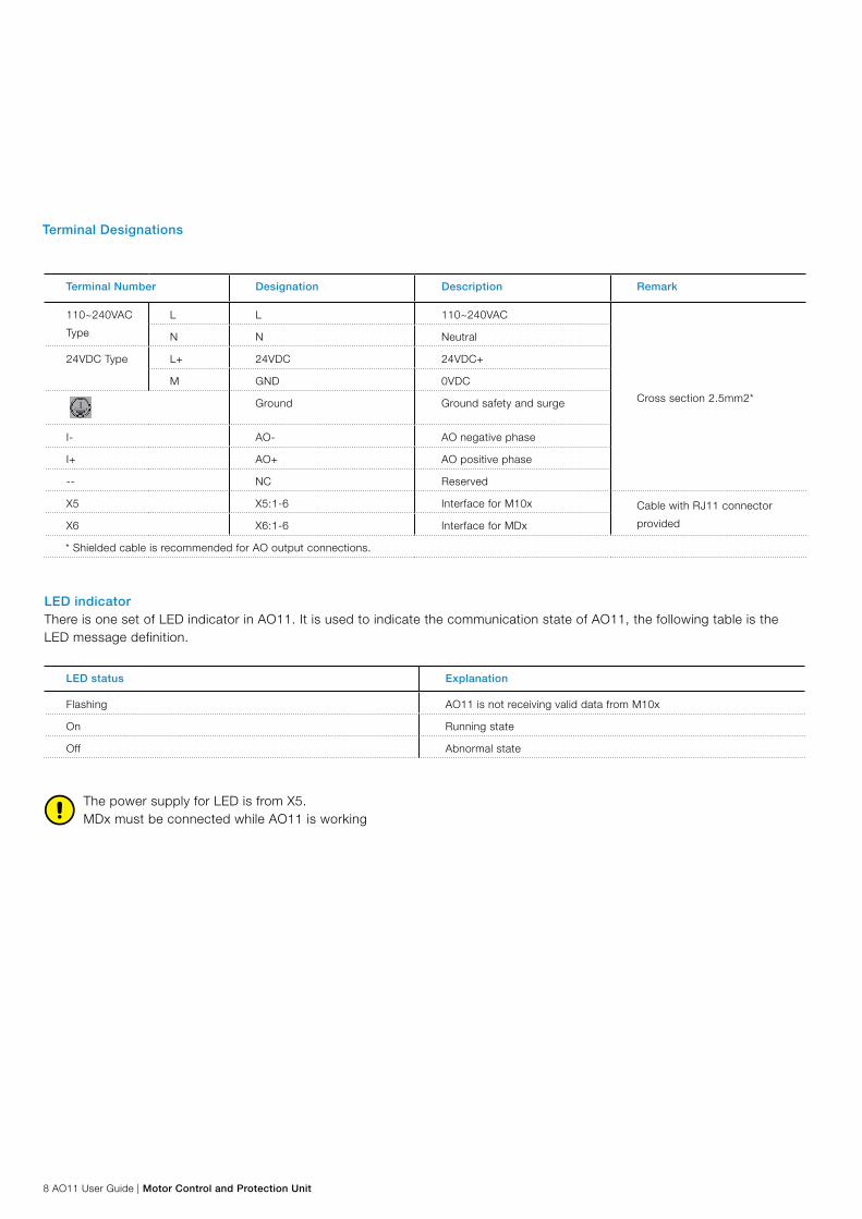
The power supply for LED is from X5. MDx must be connected while AO11 is working
Terminal Designations
Terminal Number Designation Description Remark
110~240VAC
Type
L L 110~240VAC
Cross section 2.5mm2*
N N Neutral
24VDC Type L+ 24VDC 24VDC+
M GND 0VDC
Ground Ground safety and surge
I- AO- AO negative phase
I+ AO+ AO positive phase
-- NC Reserved
X5 X5:1-6 Interface for M10x Cable with RJ11 connector
providedX6 X6:1-6 Interface for MDx
* Shielded cable is recommended for AO output connections.
LED indicatorThere is one set of LED indicator in AO11. It is used to indicate the communication state of AO11, the following table is the LED message definition.
LED status Explanation
Flashing AO11 is not receiving valid data from M10x
On Running state
Off Abnormal state

Motor Control and Protection Unit | AO11 User Guide 9
Typical Diagram
X6 X5L L
NPower Supply
I-AO-
AO+NC
LoadI+
--
N
X6 X5L+ 24DC
GNDPower Supply
I-AO-
AO+NC
LoadI+
--
M
Figure 5 Typical wiring diagram (110~240VAC)
Figure 6: Typical wiring diagram (24VDC)
Pay attention to the type of power supply of AO11 or the module may be damaged.
AO11
AO11

10 AO11 User Guide | Motor Control and Protection Unit
Parameterization
Parameterization connection
The parameters of AO11 can be configured by MCU Setup. Via mini USB-Pin physical interface on MDx, users can connect AO11 to a computer with MCU Setup software and run it to complete the parameters setting.
M10x AO11M Dx
A
B
A
B
Laptop
ComRS 466/RSe3e
Figure 7: Parameterization connection
Figure 8: main screen in MCUSetup
Enter AO11 configuration windowAfter login, MCUSetup’s main screen is displayed:

Motor Control and Protection Unit | AO11 User Guide 11
Select AO11 to enter AO11 module configuration window:
Figure 9: AO module configuration window
For more information on how to enter and use MCUSetup, please refer to separate document “MCUSetup User Guide“.
Parameters Description
AO11 has only one analog output. This analog output could be configured with functions, range and AO type. Parameters involved in AO11 are as below: AO Type Function Range

12 AO11 User Guide | Motor Control and Protection Unit
AO TypeFunction : AO11 Module Range : 0-20mA; 4-20mADefault setting : 0-20mARelated parameter : AO11 Module / FunctionDescription : The parameter defines the type of analog output signal.
FunctionFunction : AO11 Module Range : Ia, Ib, Ic, Thermal, Ua, Ub, Uc, Uab, Ubc, Uca, Frequency, I0, PF%, P, PTC value, Current Phase UnbalanceDefault setting : IaRelated parameter : AO11 TypeDescription :
Users are free to configure any parameter as shown in the table below to be converted into analog output.
Parameter M101 M102
Phase L1 Current (Ia) § §
Phase L2 Current (Ib) § §
Phase L3 Current (Ic) § §
Thermal Capacity § §
Phase L1-N Voltage (Ua) §
Phase L2-N Voltage (Ub) §
Phase L3-N Voltage (Uc) §
Phase L1-L2 Voltage (Uab) §
Phase L2-L3 Voltage (Ubc) §
Phase L1-L3 Voltage (Uca) §
Frequency §
Earth Fault Current (I0) § §
Power Factor (PF%) §
Power (P) §
PTC value §
Current Phase Unbalance § §
Table 1 Function

Motor Control and Protection Unit | AO11 User Guide 13
RangeFunction : AO11 Module Range : MIN, MAXDefault setting : -Related parameter : FunctionDescription :The parameter defines the MIN and MAX value of selected parameter. The MIN and MAX value should be in the scope of setting range and step as shown in Table 2
Parameter Setting Range Setting Step
Ia0.00-1.0A 0.01A
1.0-6300.0A 0.1A
Ib0.00-1.0A 0.01A
1.0-6300.0A 0.1A
Ic0.00-1.0A 0.01A
1.0-6300.0A 0.1A
Thermal Capacity 0%-255% 1%
Ua 0-400V 1V
Ub 0-400V 1V
Uc 0-400V 1V
Uab 0-690V 1V
Ubc 0-690V 1V
Uca 0-690V 1V
Frequency 47-53Hz, 57-63Hz 0.01Hz
I0 0-15000mA 100mA
PF% 0%-100% 1%
P0.00-1.0KW 0.01 KW
1.0-1000.00KW 0.1KW
PTC Value 10-10000Ω 1Ω
Current Phase Unbalance 0%-100% 1%
Table 2 Parameter setting range
The parameterization software can run on all of the following PC operation system:Windows 2000, Windows XP, Win 7 and Win 8.

14 AO11 User Guide | Motor Control and Protection Unit
Designation Description Identity Number
AO11 24VDCAO module, 24VDC power supply type; TA204
cable included1TNA920511R4001
AO11 110~240VACAO module, 110~240VAC type: TA204 cable
included1TNA920521R4001
TA204 Connection cable between AO module and M10x 1TNA920005R2106
Order Information
Motor Control and Protection Unit | AO11 User Guide 15
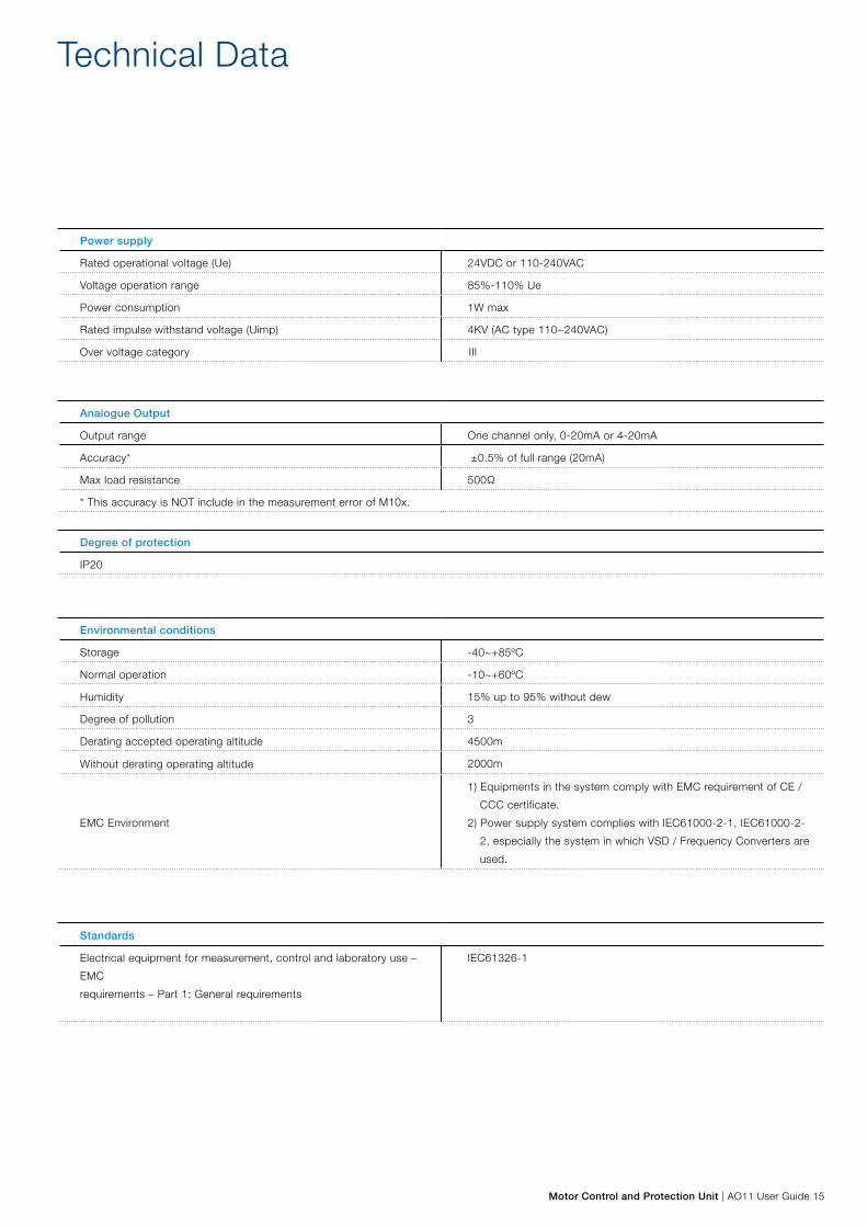
Power supply
Rated operational voltage (Ue) 24VDC or 110-240VAC
Voltage operation range 85%-110% Ue
Power consumption 1W max
Rated impulse withstand voltage (Uimp) 4KV (AC type 110~240VAC)
Over voltage category III
Environmental conditions
Storage -40~+85ºC
Normal operation -10~+60ºC
Humidity 15% up to 95% without dew
Degree of pollution 3
Derating accepted operating altitude 4500m
Without derating operating altitude 2000m
EMC Environment
1) Equipments in the system comply with EMC requirement of CE /
CCC certificate.
2) Power supply system complies with IEC61000-2-1, IEC61000-2-
2, especially the system in which VSD / Frequency Converters are
used.
Analogue Output
Output range One channel only, 0-20mA or 4-20mA
Accuracy* ±0.5% of full range (20mA)
Max load resistance 500Ω
* This accuracy is NOT include in the measurement error of M10x.
Degree of protection
IP20
Standards
Electrical equipment for measurement, control and laboratory use –
EMC
requirements – Part 1: General requirements
IEC61326-1
Technical Data
Contact us
ABB Low Voltage SystemsPublication Editor:Xiamen ABB Low Voltage Equipment Co.,LtdFujian, China
Local Contacts onwww.abb.com
Copyright© 2014 ABBAll rights reserved.
Pub
licat
ion
No.
1TN
C92
0204
D02
02