m120 stamp line - united silicone stamp line.pdf · install and understand the machine you have...
TRANSCRIPT

MEYERCORD“M”- 120 Stamp LineInstallation/Service Manual(#322-998)
Information, Orders, & Technical Support: 1-800-639-3799

This documentation is protected by United States copyright laws.Copyright 2003 by The Meyercord Company. All rights reserved.Reproduction of material is strictly prohibited without written permission.The Meyercord Company, 475 Village Drive, Carol Stream, IL. 60188.Printed in the United States.
The Meyercord Company reserves the right to make necessaryalterations in the machine specifications to meet customer requirements.Some illustrations and information in this manual may not exactly match in detail each machine.
The contents of this manual have been prepared to help you install and understand the machine you have just received. Keep this manual available for quick reference. After reading the following manual you should be able to setup, inspect and operate your M120stamp line.
Caution: Do not remove or override any safety guardingfrom this machine. The guarding has been provided to protectyour personnel from moving machine parts which can causeserious injury.
1.2 - Important Phone NumbersInformation, Orders, & Technical Support: 1-800-639-3799
Revenue Service Fax: 1-630-682-6365
Parts Dept. Fax: 1-630-682-6353

Stamp line specifications
Installation requirements: Electrical
Know your equipment
Opener to stamper alignment
Opener to stamper coupling
Attaching the closer
M120 Single wire loom
External connections
Closer pneumatic panel
Pneumatic diagram
Closer electrical control box
Closer schematic
Cold Glue Application
Filling glue tank
Reordering Glue
Stamp temperature controller
Raytek Controller Adjustment
Temperature controller schematic
Stamper electrical panel
Electrical panel schematic
Table of Contents
5
6
7
8
9
10
11
12
14
15
16
17
18
19
20
21
23
24
25
26

4
Table of Contents (Cont.)
Start up procedure
M120 operation
Rocker Adjustment
Threading the Stamps
Keyence Fiber Sensors
28
32
33
35
36

5
GENERALStamping Speed +/- 90 cartons per min.Gross Weight 680 LBS.Electrical Requirements 120VAC, 30 Amps
Dedicated lineAir Requirements 100 PSI @ 10 SCFM
MAIN FRAME DIMENSIONSLength 125”Height 53”Width 40”
“M” 120Stamper
Opener
PneumaticCloser
Feeder
Before running this equipment, become familiar with the controls andknow how to properly operate it. Before cleaning, inspecting or adjustingyour equipment, turn off the drive motors and make absolutely sure all beltsand moving parts have stopped. Don’t reach into the stamp machine whilethe power is on. If you should accidentally activate the carton sensor, themachine will cycle. If you must push a carton through the stamp machine,use an old stamp roll core or stick. Remember to keep your hands clear ofthe stamp iron when the machine is in the running mode. Never operatethe stamp equipment without proper guards, plates or safety devices inplace. Finally, do not allow untrained or unauthorized individuals to operatethe equipment.
STAMP LINE SPECIFICATIONS
6
INSTALLATION REQUIREMENTS:ELECTRICAL
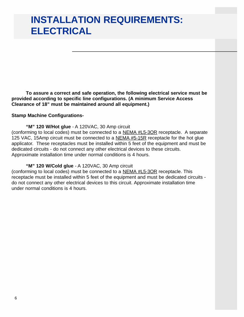
To assure a correct and safe operation, the following electrical service must beprovided according to specific line configurations. (A minimum Service AccessClearance of 18” must be maintained around all equipment.)
Stamp Machine Configurations-
“M” 120 W/Hot glue - A 120VAC, 30 Amp circuit(conforming to local codes) must be connected to a NEMA #L5-3OR receptacle. A separate125 VAC, 15Amp circuit must be connected to a NEMA #5-15R receptacle for the hot glueapplicator. These receptacles must be installed within 5 feet of the equipment and must bededicated circuits - do not connect any other electrical devices to these circuits.Approximate installation time under normal conditions is 4 hours.
“M” 120 W/Cold glue - A 120VAC, 30 Amp circuit(conforming to local codes) must be connected to a NEMA #L5-3OR receptacle. This receptacle must be installed within 5 feet of the equipment and must be dedicated circuits -do not connect any other electrical devices to this circuit. Approximate installation timeunder normal conditions is 4 hours.

7
As an operator you will be working with the “M” 120 stamp lineday after day. Your work will be easier, more pleasant and trouble-free if youmake a special point of getting acquainted with it. You will be surprised howquickly you can learn to make simple adjustments which are occasionally necessary for proper transfer of stamps.
The purpose of this line is to apply Meyercord Fuson Tax Stamps efficiently on cigarette cartons ranging in size from regulars through 120s.Unopened cigarette cartons are fed into the system, first passing through theautomatic opener where the carton flaps are opened and folded back. Thecartons next enter the stamp machine where heat and pressure transfers thetax stamps to the cigarette packages. Once the stamps are fused to thepacks, the cartons pass through to the pneumatic closer which applies glue tothe large carton flap and reseals the carton flaps using pressurized air. Theyare then put back in the case and readied for shipment.
KNOW YOUR EQUIPMENT

8
OPENER TO STAMPER ALIGNMENT
When the M120 Stamp Line is shipped to a location, the opener will already be mounted tothe stamper. However, it may be necessary to readjust the alignment when installing thisequipment. The Opener and Stamper are joined by a universal coupler which is used whentwo adjoining shafts are slightly offset. The set screws which secure this coupler need to beloosened prior to aligning the opener and stamper troughs.
Stamp troughOpener trough
When you are adjusting the vertical positioningof the opener trough to mate with the stamptrough, the (4) yoke mounting screws which aresecured to the stamper need to be loosened
Openertrough
Stamptrough
Opener yoke mounting screws
NOTE: Don’t forget to retighten thecoupler after aligning the openerwith the stamper.
set screw set screw
Universal coupler(#207-356)
When you are adjusting the horizontal positionof the opener trough to mate with the stamptrough.The 4 yoke mounting screws which aresecured to the opener need to be loosened

9
Universal Coupler
REG
BOX
KING
100s
120s
REG
BOX
KING
100s
120s
Opener eccentric positionswhen using the universalcoupler.
OPENER TO STAMPER COUPLING
Stamp eccentric positionswhen using the universalcoupler.

10
ATTACHING THE CLOSER
The pneumatic closer should be shipped with a stamper mounting bracket assembly(#322-327) already attached to its frame. When loosened, this bracket is free to moveup/down if necessary. The stamp machine frame already has pre-drilled holes located sothe two units can be brought together and secured with the hardware provided.

11
SINGLE WIRE LOOM
The M120 Singlewire Loom (#208-345) functions in the same manner as the standardSinglewire Loom (#156-205) except that the pneumatic closer power will remain on when theangle table switch or the loom’s power switch is turned off. To remove power from this closer,simply push in its red “E” Stop button.

12
EXTERNAL CONNECTIONS
95PSI
95PSI
Stamper air supply
Closer air supply
NOTE: Customer is to supply clean dry air at two inlets.The inlets are sized at 1/4”NPT. Both air supply hoses should be terminated with 1/4” Industrial quick-disconnect female couplers.
Closer power plugNEMA #5-15P
Single wire loom plugNEMA #L5-30P
Pressure roller airregulator 18PSI
Main air cut-off for closer

13

14
CLOSER PNEUMATIC PANEL
Small air jet for thelarge carton flaps
Barrel manifoldLarge air jet for thesmall carton flaps
Glue tankair supply
52psi
60psi
32psi
Shut-off valvefor glue tank
Manual valvefor all air jets
Air reservoir
Located under closer
Main aircut-off

15
PNEUMATIC DIAGRAM
IN-HOUSE AIR
Optional Compressor
GLUE TANKT-2
GLUE TANK REGULATORR-4
GLUE GUN VALVE(SPECIAL, WITH GUN)
V-4
AIR RESERVOIRT-1
MANIFOLD
SMALL AIR JET
VALVE - SMALL AIR JETV-2
LARGE AIR JET
VALVE - LARGE AIR JETV-3
VALVE - MANIFOLDV-1
REGULATOR - SMALL AIR JETR-2
REGULATOR - LARGE AIR JETR-3
REGULATOR - MANIFOLDR-1
ITEMS WITHIN DASHED BOXESARE NOT ON PNEUMATIC PANEL
MANUAL VALVEFOR ALL JETS
MV-2
MANUAL VALVEFOR GLUE TANK
MV-3
MANUAL VALVEWITH LOCK-OUT
MV-1
FILTER/REGULATORAUTO-DRAIN
FR-1
COALESCING FILTERFC-1

16
Variable frequency drivefor motor speed control
24Vdc power supply2.5 amp
Main controlrelay
Fuse blocks
Motor on/off toggle switch
Solid state relay
CLOSER ELECTRICAL BOXLocated under closer
17
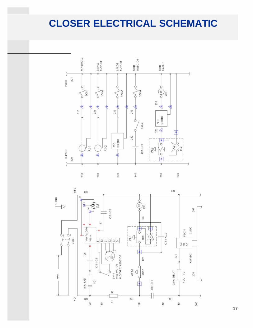
CLOSER ELECTRICAL SCHEMATIC

18
COLD GLUE APPLICATION
The binks 83Z pressure tanks are designed as a pressure container to supply cold glue ata constant preset pressure up to a maximum of 80PSI. these tanks include stainlesssteel wetted parts, a stainless steel lid and polyethylene liner, allowing use with waterborne materials.
2.8 Gallons
WARNINGPressure relief procedureHigh pressure can cause a serious injury. Pressure is maintained in a pressure tank after thesystem has been shut down. Before attempting removal of fill plug or cover, pressure mustbe relieved using the following steps.
1. Turn off the closer main air cut-off valve. This valve is located on the bottom of the closer pneumatic panel where the air line connects and should be red or orange colored.
2. Bleed off air in the tank by pulling the ring on the safety valve, located on top of the tank, until the pressure gauge indicates “0” PSI.

19
Always relieve all air pressure in the tankbefore loosening thumbscrews. Open themain air supply valve locate on pneumaticpanel and Pull the ring on the safety valveuntil the pressure bleeds down and thepressure gauge indicates “0” PSI.
Loosen thumb screws, tip lid clampsback and remove lid assembly.Pour cold glue into the tank to within 2”below the rim.
Replace the lid assembly and tightenclamps and thumbscrews securely.Restore pressure only after lid is securelytightened down.
FILLING THE GLUE TANK

20
REORDERING GLUE
TO REORDER GLUE CALL: 630-682-6200
Cold Glue Liquid Adhesive #208-367(Keep from freezing)
Hot glue chips #168-767

21
Raytek infrared controller(Heat detector for iron)
#207-729
Heat sensor cable
Watlow temperature controller#207-850
Thermo-coupler wire #207-971
24VDC power supply#207-839
Fuseblocks
Solid stateiron relay
#208-004
Located under stamper
STAMP TEMPERATURE CONTROLLER

22
RAYTEK CONTROLLER ADJUSTMENT
M-Stamp Machine, Digital Temperature ControllerMatching Iron Temperature to Displayed Controller temperatureRAYTEK MID INFRARED SENSOR ADJUSTMENT
With a target area of the iron blackened and located at the cold end of theiron, there exists a gap or offset between the desired displayed temperatureand the actual temperature of the target area. Also, there may be a gapbetween the displayed temperature on the controller and the temperaturemeasured by a reliable thermocouple-based meter. If an adjustment isdesired to narrow the gap between the displayed controller’s temperatureand the desired temperature, the emissivity setting of the Raytek MIDinfrared sensor may be adjusted to close this gap. (The emissivity of a surface is dependent upon several factors including but not limited to material, finish, reflectivity, and surrounding bodies.)
Please note that dirt, carton dust, or other obstructions on the lens of the infraredsensor may interfere with an accurate temperature reading. Keeping the lensclean is important. one may clean the lens with clean, dry, compressed air and aclean, non-abrasive cloth dampened with distilled water. any sensor with len’sdebris not removable by these two means should be sent back to the manufactur-er for professional service and calibration.

23
RAYTEK CONTROLLER ADJUSTMENT
1. Open the door of the Temperature control Box.2. Locate the Raytek MID enclosure. The cover is labeled “Raytek Thermalert MID”.3. Remove the cover by removing 4 phillips screws in the 4 corners of the enclosure.4. Locate the small LCD display in the upper right corner of the circuit board in the
enclosure.5. Locate the small push buttons (one red and 2 black) below the LCD display.6. Push the red (left) button to step through the menu of variables available.
Specifically, press the red button 4 times to get to the LCD display beginning with the letter “E” for emissivity. the numbers after the ”E” is the value for emissivity. it is adjustable at this point.
7. Press the right black button to increase the emissivity value or press the left black button to decrease the emissivity value. Raising the emissivity value will reduce the temperature read-out on the controller’s display.
8. Adjust the emissivity value so the displayed temperature on the controller is the desired temperature. The controller will attempt to get this displayed temperature to its setpoint during operation.
LCD DISPLAY
MODE
WATLOW
120VPOWER
INPUT FROM PROBE
yelwht
brn grn
torelay
RAYTEK
Raytekoutput
OUTPUT

24
TEMP. CONTROLLER SCHEMATIC
AI AND A2 ARE THE POSITIVE AND NEGATIVE WIRES OFTHE THERMOCOUPLE CONNECTION WIRE BETWEENTHE CONTROLLER AND INFRARED SENSOR BOARD.
111
4+3-
7 8
TC+,2
TC-,1
GND
OUT
GNDVDC+
113
121
102
INFRARED PROBE
A1-
A2+
A2+, RED
A1-, WHITE
WATLOW 935A
MID
141
201200
0VDC
100
100
101
140
130
120
110
L2L1
SSR-1
IRON SSR6A
168-184
1/2A
STAMP IRON
20
TC-1
TEMP CNTRLR
INFRARED
RAYTEK
168-261
2A
Power SupplyTODC
AC

25
STAMPER ELECTRICAL PANEL
NOTE:The range for the timer relayshould be set at .1 (10ths) and thesetting for the iron’s dwell timeshould be set between [.28 -.3] sec-onds as shown on the “TR1” timerrelay.
TR124Vdc
timer relay#207-949
Range
Dwell
F1
250V 2A
PL1heater bulb
#197-279
CB28 amp
breaker#162-255
SW215 A
heater sw.#147-625
SW315 A
motor sw.#147-625
SW115 A
main sw.#147-625
PB115 A
switch#184-618
CB32 amp
breaker#208-380
CB115 amp breaker
#162-244

26
ELECTRICAL PANEL SCHEMATIC
CB-2
SW-1
IRON
120VAC POWER-IN
CB-1
SW-2
SW-3CB-3
M
M-1
PL-1
GND
TC-1Temperature
ControlBox
PB-1RESET
SV-1
TR-1TIMERRELAY
Y1
A1
15
18
A2
PS-1
L1 L2
1-L2
1-L1
2-L1
100
200
300
400
500
600
700
800
900
1000F-1
BLK
BLUEBRN
WHT
BLK
WHTRED
RE
D
GR
NB
LK
WH
T
BLK
COMPONENT AND PART NUMBER CORRELATIONItem Label Qty Part Number DescriptionCB-1 1 162-244 Breaker,15A,250VAC,Push ResetCB-2 1 162-299 Breaker,8A,250VACCB-3 2 208-380 Breaker,2A,250VAC,Push ResetF-1A 1 321-524 HOLDER,Fuse,3AG,DIN,TwistF-1B 1 168-261 Fuse,2A,250V,3AG,FASTIRON 1 IRON,Heater,M120M-1 1 207-554 Motor,1/12hp,48YZ frame,115vac,1.7APB-1 1 184-618 SWITCH,15AMPPL-1 1 197-279-312 Bulb,Holder, and Cover for Heater LightPS-1 1 180-262 SENSOR,18MM SIZESW-1,2,3 3 147-625 Switch,DPST 15A 120VACSV-1 1 207-532 VALVE,3WAY,1/4NPT,Solenoid,120VACTC-1 1 207-455 Assembly,Infrared Temp ControllerTR-1 1 207-949 Relay,Timer,24VDC,240VAC@8A

27
START UP PROCEDURE
1. Turn on power switch “MAIN” located on stamp machine control panel.
2. Turn on “HEATER” switch located on stamp machine control panel.
3. Adjust heat to appropriate temperature using the “Watlow” temperature controller located under the stamp machine on the front of the electrical box cover. To set the heat level, press and hold the “SET” button then push the appropriate up/down arrow to adjust to the correct temperature. Then release the “SET” button.
4. Open main colored air valve under the stamp machine to allow air supply to energize the stamp machine’s pneumatic components. This control valve can be found where the main air hose connects to this unit. The main air regulator for the stamp machine should be adjusted for 95 psi. The second regulator which governs the pressure roller cylinders should be adjusted for 20 psi when a new stamp roll is used.
5. Open the main colored air valve on the closer to allow air supply to energize the closer pneumatic components. This control valve is located on the bottom of the closer pneumatic pane where the main air supply hose connects to this unit. The glue tank air gauge, located on top of the glue tank, should read 60 psi. Adjust if necessary.
6. Pull out the red “E” stop switch mounted on the closer frame. Press the green power “ON” button to activate the closer. If the yellow power “ON” light doesn’t light, depress this button at this time.
7. Thread stamp roll then turn on “MOTOR” switch located on the stamp machine front panel

28
M120 OPERATION
Please note that the cartons need to be placed on the in-feed tray with the smallflaps facing toward the opener.
29
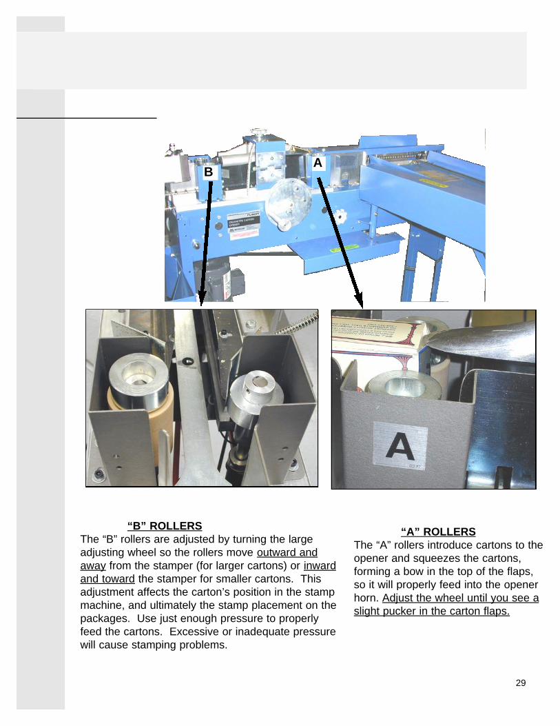
“B” ROLLERSThe “B” rollers are adjusted by turning the largeadjusting wheel so the rollers move outward andaway from the stamper (for larger cartons) or inwardand toward the stamper for smaller cartons. Thisadjustment affects the carton’s position in the stampmachine, and ultimately the stamp placement on thepackages. Use just enough pressure to properlyfeed the cartons. Excessive or inadequate pressurewill cause stamping problems.
“A” ROLLERSThe “A” rollers introduce cartons to theopener and squeezes the cartons,forming a bow in the top of the flaps,so it will properly feed into the openerhorn. Adjust the wheel until you see aslight pucker in the carton flaps.
AB
30
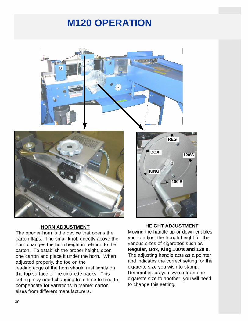
HORN ADJUSTMENTThe opener horn is the device that opens thecarton flaps. The small knob directly above thehorn changes the horn height in relation to thecarton. To establish the proper height, openone carton and place it under the horn. Whenadjusted properly, the toe on the leading edge of the horn should rest lightly onthe top surface of the cigarette packs. Thissetting may need changing from time to time tocompensate for variations in “same” cartonsizes from different manufacturers.
HEIGHT ADJUSTMENTMoving the handle up or down enablesyou to adjust the trough height for thevarious sizes of cigarettes such asRegular, Box, King,100’s and 120’s.The adjusting handle acts as a pointerand indicates the correct setting for thecigarette size you wish to stamp.Remember, as you switch from onecigarette size to another, you will needto change this setting.
REG
BOX
KING
100’S
120’S
M120 OPERATION

31
Rocker cylinder
Gate cylinder (not shown)
Photo eye
Pressure roller cylinders

32
As the carton enters into the stamp machine, it “trips” the photo eye which activates thegate cylinder to extend and release the gate. Approximately the same time, the rockercylinder activates and rotates the rocker downward to apply the cigarette stamps. thenext carton entering the stamp trough will push the first carton through the expeller atwhich time the gate will close and the cycle begins again.
Rotary Actuatorfor RockerAsmbly
Left PressureRoller Cylinder
Right PressureRoller Cylinder
GateCylinder
Regulator,Pressure
Roller
Valve, Rockerand Gate
Filter /Regulator
100psigAir
Supply
ManualShut-off
Gate assembly
Gate cylinder
90 psi
18 psi
COMPONENT AND PART NUMBER CORRELATIONItem Name Qty Part Number Description
Filter / Regulator 1 207488 ASSEMBLY,REG,FILTER,125psig,1/4NPT,M120Valve, Rocker and Gate 1 207543 Assembly,VALVE,3WAY,1/4NPT,Solenoid,120VACRegulator, Pressure Roller 1 207521 Assembly,Regulator, Precision High FlowPressure Roller Cylinder 2 148670 Cylinder,3/4" Bore,1/2" StrokeRotary Actuator for Rocker 1 207323 MOTOR,Pneumatic,Rotary VaneGate Cylinder 1 208181 Cylinder,1/2" Bore,1" Stroke
M120 OPERATION

33
ROCKER ADJUSTMENT
1. Turn Stamp machine main power “OFF”.2. Set the stamp line height to “REG” position.3. Place “REG” calibration block under the next iron pad to come down
over the stamp machine trough.4. Using a 9/16” wrench, loosen the two locking nuts which secures both
adjusting screws on the rocker cylinder.5. Turn on the “MAIN” power and “MOTOR” switches on the stamp
machine.6. Press and hold the “RESET” button and observe iron contact with the
calibration block.7. If the iron needs to travel down further to make more positive contact
with the calibration block use a 3/16” allen wrench to turn the loweradjusting screw counter-clockwise (while the iron is still in the “down” (postion) to lower the rocker’s down postion. Turn this screw clock-wise if too much down travel or pressure exists.
8. After sufficient downward pressure is achieved release the “RESET” button and tighten the locking nut on the lower adjusting screw. You may have to hold the adjusting screw steady with the allen wrench while tightening its locking nut.
9. Press the “RESET” button several times and observe the upward travel of the rocker assembly. If the peg roller does not advance after cycling the unit three times, the rocker may not be traveling up high enough.Using the 3/16” allen wrench, turn the upper adjusting screw counter-clockwise to raise the rocker higher so the pinned ratchet engages on the gear/pawl assembly.
NOTE: When adjusting the rocker, the rocker must be inthe down position (Hold reset button ) when adjusting thedownward travel and up when adjusting the upward travel.

34
“REGULAR” calibration blockPart #147-383
Locking nut
Locking nut
DOWN
UP
Hold the “RESET” button in whenadjusting the downward pressure onthe calibration block.
Lower adjusting screwUsed to increase or to decrease thedownward travel
Upper adjusting screwUsed to increase or to decrease theupward travel

35
THREADING THE STAMPS
and heldfirmly between the two core holders. It is veryimportant that the stamp roll sits flush againstthe left core holder. The paper must lead off thetop of the roll.
over the fiber roller (A),over the trough (B), and under the brass roller(C). Pull the paper until the first row of stampslines up to the inside edge of the front trough side.
between the two black shafts,over and between the tan roller (D), and the pegroller (E). Wrap the paper around the peg rollerand beneath the next pressure roller (F). Theholes in the paper should line up on the pegs (E).

36
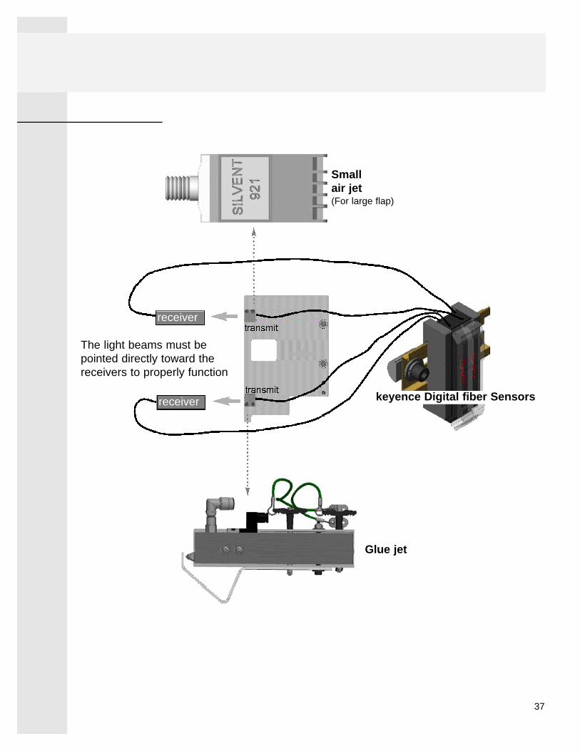
The glue nozzle and the small air jet are triggered when a carton passes through the lightbeams which are emitted from fiber units, as shown on the next page. The plate wherethese fiber units are mounted is located adjacent to the glue nozzle. The keyence fibersensors are located adjacent to the motor and can be accesses by opening the smalleraccess panel which is above the motor. On top of these sensors, there are two fiber opticcables. One for transmitting a light signal and one for receiving the light signal as shownbelow.
output selector
Manual button(increase)
Mode button
Current value
Preset value
Manual button(decrease)
keyence Digital fiber Sensor
Note:If either the Glue jet or the Small air jet doesn’t “fire”when a carton passes through their associated lightbeams, first verify that the tranmit and receive fiberunits are in allignment. While observing the lightbeams, the plate that the transmit units are mountedon can be loosened and adjusted slightly to properlyalign.
SET
The Preset value should always be approximately4X greater than the Current value as shown here.This applies to the keyence sensor for the glue jetas well as the sensor for the small air jet. If thisvalue is not great enough, than its associatedoutput device will not respond.To increse this value, carefully push the lower manual button until this value is sufficiently raised.
KEYENCE FIBER SENSORS
37
receiver
receiver keyence Digital fiber Sensors
Glue jet
Smallair jet(For large flap)
The light beams must bepointed directly toward thereceivers to properly function