m16 ip67 miniature 423 series - binder-usa.com · 49 ~ 60 Ø 18,5 m16 x 0,75 ~ 60 Ø 18,5 ~ 60 Ø...
TRANSCRIPT

49
~ 60
Ø 18
,5M1
6 x 0,
75
~ 60
Ø 18
,5
~ 60
Ø 18
,5
3 DIN
6–8 mm
99 5605 15 03 99 5605 00 034 99 5609 15 04 99 5609 00 045 99 5613 15 05 99 5613 00 056 DIN 99 5621 15 06 99 5621 00 067 99 5625 15 07 99 5625 00 078 DIN 99 5671 15 08 99 5671 00 0812 99 5629 15 12 99 5629 00 1219 99 5661 15 19 99 5661 00 19
~ 60
Ø 18
,5M1
6 x 0,
75
3 DIN
6–8 mm
99 5605 210 03 –4 99 5609 210 04 99 5609 700 045 99 5613 210 05 99 5613 700 056 DIN – 99 5621 700 067 – 99 5625 700 078 DIN – 99 5671 700 08
Miniature 423 seriesM16 IP67
Specifications
Description Drawing
Male cable connector with shielding ring/cable clamp, shieldable, solder termination
Crimp and strip contacts see page 56
Crimp and strip contacts see page 56
Male cable connector with shielding ring/cable clamp, shieldable, solder termination
Male cable connector with cable clamp, screw clamp connection/crimp connection, shieldable
Male cable connector with cable clamp, screw clamp connection/crimp connection, shieldable
• Screw termination M16• Degree of protection IP67• Solder-/Crimp-/Screw clamp
termination• Moulded versions• shieldable• Acc. to DIN EN 61076-2-106• AISG compatible
certified under number 20120329-E30 2391
Contacts Cable outlet Shielding ring Cable clamp3 DIN
4–6 mm
99 5105 15 03 99 5105 00 034 99 5109 15 04 99 5109 00 045 99 5113 15 05 99 5113 00 056 DIN 99 5121 15 06 99 5121 00 067 99 5125 15 07 99 5125 00 078 DIN 99 5171 15 08 99 5171 00 0812 99 5129 15 12 99 5129 00 1219 99 5461 15 19 99 5461 00 19
Contacts Cable outlet Screw clamp Crimp3 DIN
4–6 mm
99 5105 210 03 –4 99 5109 210 04 99 5109 700 045 99 5113 210 05 99 5113 700 056 DIN – 99 5121 700 067 – 99 5125 700 078 DIN – 99 5171 700 08
Contacts 3 DIN 4 5 6 DIN 7 8 DIN 12 19
Wire gauge max. 0,75 mm2 (max. AWG 20) max. 0,25 mm2 (max. AWG 24)
Mechanical operation > 500 Mating cycles
Temperature range – 40 °C /+ 95 °C
Rated voltage 250 V (32 V) 125 V (32 V) 60 V (32 V)
Pollution degree 1 (2) 1)
Rated current (40°C) 7 A 6 A 5 A 3 A
Contact plating Ag (Silver) Au (Gold)
Material of housing CuZn (brass, nickel plated)
1) In case of pollution degree 2, overvoltage category II rated voltage is reduced to 32 V. . More versions and information on www.binder-connector.com
50
4 99 5109 750 04 99 5609 750 045 99 5113 750 05 99 5613 750 056 DIN 99 5121 750 06 99 5621 750 067 99 5125 750 07 99 5625 750 078 DIN 99 5171 750 08 99 5671 750 08
~ 45
Ø 18
,5
M 16
x 0,7
5
Ø 4,1
–7,8
4
4–8 mm
99 5109 740 045 99 5113 740 056 DIN 99 5121 740 067 99 5125 740 078 DIN 99 5171 740 08
~ 5430,8
Ø 18
37,1
M16 x 0,75
20Ø
18,5
30,850,8 L
52
Ø 20M16 x 0,75
41,5 L
18,8
35,3
21,6
Ø 14
Ø 17
5 x 0,25
2 m
79 6213 200 05 79 6313 200 056 DIN x 0,25 – 79 6317 200 068 DIN x 0,25 79 6271 200 08 79 6371 200 0812 x 0,25 79 6229 200 12 79 6329 200 12
Miniature 423 · 425 seriesM16 IP67Description Drawing
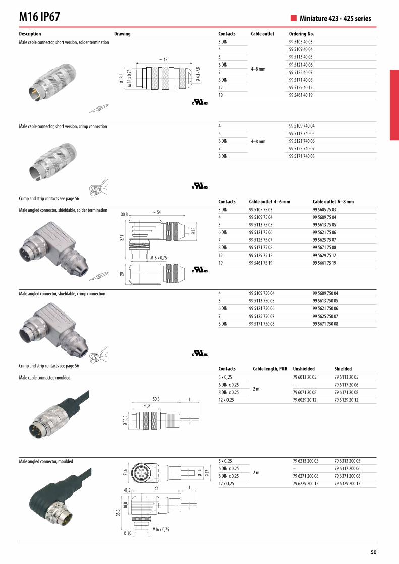
Male cable connector, short version, solder termination
Crimp and strip contacts see page 56
Crimp and strip contacts see page 56
Male cable connector, short version, crimp connection
Male angled connector, shieldable, solder termination
Male angled connector, shieldable, crimp connection
Male cable connector, moulded
Male angled connector, moulded
Contacts Cable outlet Ordering-No.3 DIN
4–8 mm
99 5105 40 034 99 5109 40 045 99 5113 40 056 DIN 99 5121 40 067 99 5125 40 078 DIN 99 5171 40 0812 99 5129 40 1219 99 5461 40 19
Contacts Cable outlet 4–6 mm Cable outlet 6–8 mm3 DIN 99 5105 75 03 99 5605 75 034 99 5109 75 04 99 5609 75 045 99 5113 75 05 99 5613 75 056 DIN 99 5121 75 06 99 5621 75 067 99 5125 75 07 99 5625 75 078 DIN 99 5171 75 08 99 5671 75 0812 99 5129 75 12 99 5629 75 1219 99 5461 75 19 99 5661 75 19
Contacts Cable length, PUR Unshielded Shielded5 x 0,25
2 m
79 6013 20 05 79 6113 20 056 DIN x 0,25 – 79 6117 20 068 DIN x 0,25 79 6071 20 08 79 6171 20 0812 x 0,25 79 6029 20 12 79 6129 20 12

51
3 DIN
6–8 mm
99 5606 15 03 99 5606 00 034 99 5610 15 04 99 5610 00 045 99 5614 15 05 99 5614 00 056 DIN 99 5622 15 06 99 5622 00 067 99 5626 15 07 99 5626 00 078 DIN 99 5672 15 08 99 5672 00 0812 99 5630 15 12 99 5630 00 1219 99 5662 15 19 99 5662 00 19
3 DIN
6–8 mm
99 5606 210 03 –4 99 5610 210 04 99 5610 700 045 99 5614 210 05 99 5614 700 056 DIN – 99 5622 700 067 – 99 5626 700 078 DIN – 99 5672 700 08
4
4–8 mm
99 5110 740 045 99 5114 740 056 DIN 99 5122 740 067 99 5126 740 078 DIN 99 5172 740 08
~ 60
Ø 18
,5
~ 60
Ø 18
,5
~ 60
Ø 18
,5M1
6 x 0,
75
~ 60
Ø 18
,5M1
6 x 0,
75
~ 45
Ø 18
,5M1
6 x 0,
75
Ø 4,1
–7,8
Ø 4,1
–7,8
Miniature 423 seriesM16 IP67Description Drawing
Female cable connector with shielding ring/cable clamp, shieldable
Crimp and strip contacts see page 56
Female cable connector with shielding ring/cable clamp, shieldable
Female cable connector with cable clamp, screw clamp connection/crimp connection, shieldable
Female cable connector with cable clamp, screw clamp connection/crimp connection, shieldable
Contacts Cable outlet Shielding ring cable clamp3 DIN
4–6 mm
99 5106 15 03 99 5106 00 034 99 5110 15 04 99 5110 00 045 99 5114 15 05 99 5114 00 056 DIN 99 5122 15 06 99 5122 00 067 99 5126 15 07 99 5126 00 078 DIN 99 5172 15 08 99 5172 00 0812 99 5130 15 12 99 5130 00 1219 99 5462 15 19 99 5462 00 19
Contacts Cable outlet Ordering-No.3 DIN
4–8 mm
99 5106 40 034 99 5110 40 045 99 5114 40 056 DIN 99 5122 40 067 99 5126 40 078 DIN 99 5172 40 0812 99 5130 40 1219 99 5462 40 19
Contacts Cable outlet Screw clamp Crimp3 DIN
4–6 mm
99 5106 210 03 –4 99 5110 210 04 99 5110 700 045 99 5114 210 05 99 5114 700 056 DIN – 99 5122 700 067 – 99 5126 700 078 DIN – 99 5172 700 08
Female cable connector, short version, solder termination
Female cable connector, short version, crimp connection

52
4 99 5110 750 04 99 5610 750 045 99 5114 750 05 99 5614 750 056 DIN 99 5122 750 06 99 5622 750 067 99 5126 750 07 99 5626 750 078 DIN 99 5172 750 08 99 5672 750 08
~ 5430,8
Ø 18
37,4
M16 x 0,75
20
52
Ø 20
41,5 L
18,8
35,6
21,6
Ø 14
Ø 17
Ø 18
,5
31,251,2 L
5 x 0,25
2 m
79 6214 200 05 79 6314 200 056 DIN x 0,25 – 79 6318 200 068 DIN x 0,25 79 6272 200 08 79 6372 200 0812 x 0,25 79 6230 200 12 79 6330 200 12
Miniature 423 · 425 seriesM16 IP67Description Drawing
Crimp and strip contacts see page 56
Female angled connector, shieldable
Female angled connector, crimp connection, shieldable
Female cable connector, moulded
Female angled connector, moulded
Component part drawingCable connectors, solder termination, with shielding ring Cable connectors, solder termination, with cable clampMale ring nut/
Female ring nut with sealFemale insert/Male insertDistance sleeveShielding ringShield clamping ringSleeveSealPinch ringPressing screw
Male ring nut/Female ring nut with sealFemale insert/Male insertCable clampSleeveSealThrust collarPressing screw
Male ring nut/Female ring nut with sealFemale insert/Male insertCable clampSleeveSealThrust collarPressing screw
Male ring nut/Female ring nutFemale insert/Male insertFemale contact/Male contactCable clampSleeveSealThrust collarPressing screw
Cable connectors with screw clamp connection Cable connectors with crimp connection
Contacts Cable outlet 4–6 mm Cable outlet 6–8 mm3 DIN 99 5106 75 03 99 5606 75 034 99 5110 75 04 99 5610 75 045 99 5114 75 05 99 5614 75 056 DIN 99 5122 75 06 99 5622 75 067 99 5126 75 07 99 5626 75 078 DIN 99 5172 75 08 99 5672 75 0812 99 5130 75 12 99 5630 75 1219 99 5462 75 19 99 5662 75 19
Contacts Cable length, PUR Unshielded Shielded5 x 0,25
2 m
79 6014 20 05 79 6114 20 056 DIN x 0,25 – 79 6118 20 068 DIN x 0,25 79 6072 20 08 79 6172 20 0812 x 0,25 79 6030 20 12 79 6130 20 12

53
M16 x
0,75
Ø 21
,5
~68
38
M16 x 0,75Ø 24
45,5
28,5
~ 32
Ø 19
34
M16 x 0,75Ø 24
43,5
~ 32
Ø 19
M16 x
0,75
Ø 21
,5
~66
3 DIN 99 0105 106 03 99 0105 75 034 99 0109 106 04 99 0109 75 045 99 0113 106 05 99 0113 75 056 DIN 99 0121 106 06 99 0121 75 067 99 0125 106 07 99 0125 75 078 DIN 99 0171 106 08 99 0171 75 0812 99 0129 106 12 99 0129 75 1219 99 0461 106 19 99 0461 75 19
3 DIN 99 0106 106 03 99 0106 75 034 99 0110 106 04 99 0110 75 045 99 0114 106 05 99 0114 75 056 DIN 99 0122 106 06 99 0122 75 067 99 0126 106 07 99 0126 75 078 DIN 99 0172 106 08 99 0172 75 0812 99 0130 106 12 99 0130 75 1219 99 0462 106 19 99 0462 75 19
3 DIN 09 0106 25 03 09 0106 70 034 09 0110 25 04 09 0110 70 045 09 0114 25 05 09 0114 70 056 DIN 09 0122 25 06 09 0122 70 067 09 0126 25 07 09 0126 70 078 DIN 09 0172 25 08 09 0172 70 0812 09 0130 25 12 09 0130 70 1219 09 0462 25 19 09 0462 70 19
Miniature 423 · 723 seriesM16 IP67
Description Drawing
Male cable connector, solder termination
Male angled connector, solder termination
Female cable connector, solder termination
Female angled connector, solder termination
Component part drawingCable connectors Male ring nut/
Female ring nut with sealFemale insert assembled/Male insert assembledHousingSealPinch ringPressing screw
Male ring nut/Female ring nutFemale insert/Male insertAngled housingSealPinch ringPressing screwCable outlet adjustable in 4 positions
Angled connectors
Contacts Cable outlet 4–6 mm Cable outlet 6–8 mm3 DIN 09 0105 25 03 09 0105 70 034 09 0109 25 04 09 0109 70 045 09 0113 25 05 09 0113 70 056 DIN 09 0121 25 06 09 0121 70 067 09 0125 25 07 09 0125 70 078 DIN 09 0171 25 08 09 0171 70 0812 09 0129 25 12 09 0129 70 1219 09 0461 25 19 09 0461 70 19
Component part drawing
Cable connectors, short version Male ring nut/Female ring nut with sealFemale insert/Male insertCable clampSeal 4–6 mm/6–8 mmPressing screw
Male ring nut and housing/Female ring nut and housing with sealPositioning sleeve with O-ring 12,5 x 1,1Female insert/Male insertDistance sleeve, Shaped seal, CoverO-ring 9 x 1,5Shielding ring, SealPinch ring, Pressing screwCable outlet adjustable in 4 positions
Angled connectors

54
3 DIN 09 0107 80 03 –4 09 0111 80 04 09 0111 782 045 09 0115 80 05 09 0115 782 056 DIN 09 0123 80 06 09 0123 782 067 09 0127 80 07 09 0127 782 078 DIN 09 0173 80 08 09 0173 782 0812 09 0131 80 12 –19 09 0463 80 19 –
3 DIN 09 0107 90 034 09 0111 90 045 09 0115 90 056 DIN 09 0123 90 067 09 0127 90 078 DIN 09 0173 90 0812 09 0131 90 1219 09 0463 90 19
5 09 0115 290 056 DIN 09 0123 290 068 DIN 09 0173 290 0812 09 0131 290 1219 09 0463 290 19
4 09 0111 700 045 09 0115 700 056 DIN 09 0123 700 067 09 0127 700 078 DIN 09 0173 700 08
4 09 0111 780 045 09 0115 780 056 DIN 09 0123 780 067 09 0127 780 078 DIN 09 0173 780 08
169,5
M16 x
0,75
M18 x
0,75
Ø 20
1 min.3 max.
3
3Ø
20
1,5
2–8 pol.
12–24 pol.
16,5
7
M16 x
0,75
M18 x
0,75
Ø 20
1 min.3,5 max.
15
3
Ø 20
1,5
2–8 pol.
12–24 pol.
16,5
7
M16 x
0,75
M18 x
0,75
Ø 20
1 min.3,5 max.
15
3
Ø 20
1,58,1
3,5
7,8
Ø 0,75
Ø 0,6
2–8 pol.
12–24 pol.
3,5 Ø 0,7
5
M18 x
0,75
Ø 20
157,17
9,6
3,5
3
1 min.3,5 max.
M16 x
0,75
9,4
1Ø
0,75
5–8 pol.
12 pol.
169,5
M18 x
0,75
Ø 20
1 min.3,5 max.
3
1,5
21,4
M16 x
0,75
Ø 20
16,57
M18 x
0,75
Ø 20
1 min.3,5 max.
3
1,5
Ø 20
21,4
M16 x
0,75
Description Drawing
Male panel mount connector, solder/with single wires (200 mm), AWG 22
Male panel mount connector, solder, front fastened/with single wires (200 mm), AWG 22
Male panel mount connector, dip-solder, front fastened
Male panel mount connector, dip-solder, front fastened, with shield connection
Male panel mount connector, crimp
Male panel mount connector, crimp, front fastened
Contacts Male panel mount connector solder Male panel mount connector with single wires3 DIN 09 0107 00 03 –4 09 0111 00 04 09 0111 702 045 09 0115 00 05 09 0115 702 056 DIN 09 0123 00 06 09 0123 702 067 09 0127 00 07 09 0127 702 078 DIN 09 0173 00 08 09 0173 702 0812 09 0131 00 12 –19 09 0463 00 19 –
Crimp and strip contacts see page 56
Crimp and strip contacts see page 56
Miniature Series 723M16 IP67
NEW
NEW

55
3 DIN 09 0108 80 03 –4 09 0112 80 04 09 0112 782 045 09 0116 80 05 09 0116 782 056 DIN 09 0124 80 06 09 0124 782 067 09 0128 80 07 09 0128 782 078 DIN 09 0174 80 08 09 0174 782 0812 09 0132 80 12 –19 09 0464 80 19 –
3 DIN 09 0108 90 034 09 0112 90 045 09 0116 90 056 DIN 09 0124 90 067 09 0128 90 078 DIN 09 0174 90 0812 09 0132 90 1219 09 0464 90 19
4 09 0112 700 045 09 0116 700 056 DIN 09 0124 700 067 09 0128 700 078 DIN 09 0174 700 08
4 09 0112 780 045 09 0116 780 056 DIN 09 0124 780 067 09 0128 780 078 DIN 09 0174 780 08
5,5
M18 x
0,75
8,6
M16 x
0,75
Ø 20
12,2
1,5
31 min.5 max.
10,1
12+19 pol.
5+8 pol.
3–7 pol.
4,7
M18 x
0,75
7,5
Ø 20
12,21,5
3 1 min.4 max.
5,5
Ø 20
12,5
12+19 pol.
5+8 pol.
3–7 pol.
34,51,57,5
7,8 4,712,5
Ø 20
1 x 0,3
M18 x
0,75
M16 x
0,75
3 1 min.4 max.
12+19 pol.
5+8 pol.
3–7 pol.
M18 x
0,75
Ø 20
1 min.4 max.
7,5
3
Ø 20
1,5
4,512,57,8 4,7
3
1 x 0,
3
0,25
16,515
M16 x
0,75
Ø 20
M18 x
0,75
Ø 20
3
1,58,1
3,5
Ø 0,7
5
~3,5
0,25
7
1 min.3,5 max.
11,8
M18 x
0,75
Ø 20
1 min.5 max.
3
1,5
Ø 20
14,8
7,5
M18 x
0,75
Ø 20
Ø 20
11,8
3
1 min.5 max.
1,5
14,8
Description Drawing
Female panel mount connector, solder/with single wires (200 mm), AWG 22
Female panel mount connector, solder, front fastened/with single wires (200 mm), AWG 22
Female panel mount connector, dip-solder, front fastened
Female panel mount connector, crimp
Female panel mount connector, crimp, front fastened
Male panel mount connector/Female panel mount connector with flexible PCB, front fastened
Contacts Female panel mount connector solder Female panel mount connector with single wires3 DIN 09 0108 00 03 –4 09 0112 00 04 09 0112 702 045 09 0116 00 05 09 0116 702 056 DIN 09 0124 00 06 09 0124 702 067 09 0128 00 07 09 0128 702 078 DIN 09 0174 00 08 09 0174 702 0812 09 0132 00 12 –19 09 0464 00 19 –
Crimp and strip contacts see page 56
Crimp and strip contacts see page 56Male panel mount connector Female panel mount connector
7 09 0127 65 07 09 0128 65 078 DIN 09 0173 65 08 09 0174 65 08
1209 0131 65 12 single-row 09 0132 65 12 single-row09 0131 66 12 double-row 09 0132 66 12 double-row
Miniature Series 723M16 IP67
NEW
NEW

56
ABC
D
EF
GH
JK
LM
A
BC
D
E
F
GH
J
K
LM
A
B
C
DE F
G
H
I
KL
M
NO
P RST
U
A
B
C
EFG
H
I
KL
M
NO
PRST
U
D
13
2
1 3
2
1
23
4
1
2 3
4
1
2
3
4
5
1
2
3
4
5
1
2
34
56
1
2
34
56
1
2
34
5
6
7
1
2
34
5
6
7
7
1
2
3
45
68
7
1
2
3
4 5
68
8,3
Ø 18
17
R 2
20,5
9,2
Ø 1,5
Ø 2,2
5
14,3
8,1
Ø 2,2
5
Contact arrangements female insert (mating side)
Panel cut out
3 DIN contacts 4 contacts 5 contacts 7 contacts6 DIN contacts 8 DIN contacts
Contact arrangements male insert (mating side)
12 contacts 19 contacts
Description Drawing
Male contact, PU 50 pieces
Female contact, PU 50 pieces
Strip contact (Male)
Strip contact (Female)
Contact-Ø Insulating-Ø Wire gauge PU Pieces Ordering-No.
1,5 mm
1,0–2,0 mm
0,14–0,25 mm2
Single 50 61 0799 085 00Strip 200 65 0799 085 01Strip 2000 65 0799 085 02
0,35–0,5 mm2
Single 50 61 0795 085 00Strip 200 65 0795 085 01Strip 2000 65 0795 085 02
1,6–2,1 mm 0,75–1,0 mm2
Single 50 61 0796 085 00Strip 200 65 0796 085 01Strip 2000 65 0796 085 02
Miniature 423 · 723 · 425 seriesM16 IP67
Colour of wires of moulded cable connectors5 contacts 6 contacts 8 contacts 12 contacts12345
whitebrownblueblackgrey
123456
redblackyellowbluewhitegreen
12345678
whitebrowngreenyellowgreypinkbluered
ABC DEFGH
whitebrowngreenyellowgreypinkbluered
JKLM
blackpurplegrey/pinkred/blue
4–8 contacts12345678
whitebrowngreenyellowgreypinkbluered
1,5 mm
1,0–2,0 mm
0,14–0,25 mm2
Single 50 61 0800 085 00Strip 200 65 0800 085 01Strip 2000 65 0800 085 02
0,35–0,5 mm2
Single 50 61 0797 085 00Strip 200 65 0797 085 01Strip 2000 65 0797 085 02
1,6–2,1 mm 0,75–1,0 mm2
Single 50 61 0798 085 00Strip 200 65 0798 085 01Strip 2000 65 0798 085 02
Colour of wires of panel mount connectors
Recommended drill holes
2 – 8 contacts 1,1 mm12 – 24 contacts 0,8 mm

57
08 1078 000 000
3 mm 08 1080 000 00018 mm 08 2671 000 000
Ø 6
510
,5
Ø 20
~ 125
Ø 6
513
,5
Ø 20
7
~ 125
Ø 670
510
,5
Ø 20Ø D
Ø 6
513
,5
Ø 20
7
70
Ø D
45
25
1,5
M18 x 0,75
20
1
13
208,4
Ø 3,2
26
Ø 18
,1
1
08 0045 000 001
Protection cap for male cable connectors
Protection cap for female cable connectors
Protection cap for male panel mount connectors
Protection cap for female panel mount connectors
Mounting spanner for panel mount connectors
Rectangular flange for panel mount connectors
Ring nut for fixing thread
Description Drawing Ordering-No.08 1077 000 000
Hole-Ø D Ordering-No.3 mm 08 1079 000 00018 mm 08 2670 000 000
Ordering-No.07 0010 001
Miniature 423 · 723 · 425 seriesM16 IP67
01 0010 001 with knurled screw

58
52,5M18 x 0,75
SW 20mm
02 0007 000
02 1785 000
66 0001 014 10067 0001 014 100
07 0088 000
Ø 21,5
6,4
Leiterplattendicke: max. 1,5 mmThickness of PCB: max. 1,5 mm
31,5
20
10,58
08 2668 000 001
Ø 21
3
129 0,3 min./4 max.
M18 x
0,75
3
22
2
30,713
Ø 22
Ø 18 4,8
Description Drawing
Solder eye ring
Blind plug
Ordering-No.04 0186 009
Thickness Ordering-No.2,5 mm 01 0146 0015 mm 01 5006 001
Hexagonal nut
Distance sleeve for panel mount connectors, dip-solder version
Mounting spanner for straight, shieldable cable connectors
Crimping tool for single contacts
Extraction tool for crimp contacts
PCB thickness: max. 1,5 mm
Miniature 423 · 723 · 425 seriesM16 IP67
Crimping tool for strip contacts