m24 or 1 unc (by others) all jacking bracket
TRANSCRIPT

General Notes:
This instruction covers the installation of a resilient mounted system for a marine propulsion en-gine driving a rigidly mounted gearbox through a flexible coupling utilising an independent jacking arrangement.
We recommend that the vessel is afloat during alignment and installation of the mounts.
Read in conjunction with Leaflet PL001, Drawing No's S048 (std metric fixings) S183 (std imperi-al fixings), S056, S222, Data Sheets DS094 & DS096 (and the mount installation drawing if is-sued for this application).
Procedure:
1. Engine feet (or engine brackets) and jacking brackets are to be fitted to the engine housing typically as shown in Figure 1 below. Ensure the engine foot/bracket has 2 tapped holes at 148mm centres for mount domed ended jacking screws. See figure 8 on page 6.
2. Fit the mounts, complete with soleplates, to the underside of the engine feet/brackets. Be-tween the top of each mount and the underside of each engine foot, a proof packing plate S222 should be fitted. These are to be drilled and slotted to allow them to be withdrawn dur-ing mount replacement in the future. Insert the M12 domed end levelling screws in the base of the mount making sure that they are suitably covered with an anti seizure lubricant prior to fitment.
3. A jacking set screw, complete with locking nut, is to be fitted in the tapped hole in each en-gine jacking bracket. The set screw shall have a domed end for location in the dimple on the topside of the loose dimpled plates typically as shown below in Figure 1. All jacking bracket components supplied by others.
1 of 9
11
15 May 2019
A.N.M
Instructions for Installation of Type TSC Size T1 & T2 Combined Steel Spring and Rubber Spring Unit Isolators - Marine Propulsion
Domed endedJacking Screws(By others)
TSC Isolator
M/c Bedframe
Soleplate
ProofPacking Plate
Engine footor bracket
EngineJacking Bracket
Loose Dimpled Plate
Domed JackingSet Screw
4 No. M12Levelling Screws(By Others)
Seating
Loosened lock nut
All Jacking BracketComponents(By Others)
Mount Fixing BoltM24 or 1" UNC (By Others)
Figure 1

4. The following brackets are to be supplied and fitted by the shipbuilder:-
i. End restraint brackets to be bolted to the ship’s seating on each side of the engine. The brackets are to be fitted with domed end set screws and lock nuts that act directly on the rib of engine jacking bracket to enable the coupling gap to be adjusted during alignment (2 or 4 brackets may be required). See Figure 2a above. Never push against the mounts.
ii. Transverse thrust brackets to be bolted to the ship's seating complete with domed end set screws and lock nuts that act directly on the outside face of engine jacking bracket to enable transverse alignment to be accurately attained. See Figure 2b above. Never push against the mounts.
5. Grease the top and bottom surfaces of the loose dimpled plates to allow easier movement of the engine along the ship's seating. Position the greased loose dimpled plates on the ship's engine seating under the jacking bracket screws.
6. The engine complete with its mounts and jacking brackets should be craned in, ensuring that the domed ends of the jacking set screws locate in the dimples on the top surface of the greased loose plates. The gap between the underside of the mount soleplate and the ship's seating is checked to confirm that there is adequate clearance for chocking referring to the chock manufacturers guidelines for minimum thickness. See Figure 3 below.
2 of 9
11
15 May 2019
A.N.M
Instructions for Installation of Type TSC Size T1 & T2 Combined Steel Spring and Rubber Spring Unit Isolators - Marine Propulsion
Seating
Drive EndRestraints BracketShipbuilders Supply
Seating
TransverseThrust BracketShipbuilders Supply
M/c BedframeProofPacking Plate Engine
Jacking Bracket
Loose Dimpled Plate
Domed JackingSet Screw
4 No. M12Levelling Screws(By Others)
Seating
Loosened lock nut
Adeq
uate
Cle
ara
nce
for
Chockin
g
Mount Fixing BoltM24 or 1" UNC (By Others)
Domed endedJacking Screws(By others)
Soleplate
Figure 3
Craned or Lowered In
Figure 2a Figure 2b

7. Adjust the side and end restraint bracket adjusting screws so that they are in contact with the engine jacking brackets.
8. Alignment of the engine to the gearbox should now be effected using the domed jacking set screws and transverse and end thrust restraint screws. Once the alignment procedure is complete, the transverse and end restraint bracket screws and the domed jacking set screws must be secured in position by the lock nuts.
NOTE - Confirm your target settings prior to starting alignment. The longitudinal deflection, in-stalled height and transverse offset should be confirmed based on your specific installation draw-ing and the engine manufacturers recommendations regarding thermal growth. When in doubt contact Christie & Grey for guidance. Careful alignment designed to compensate for these fac-tors will reduce maintenance and improve the overall performance and service life of the system.
9. Holes for the mount four no. H.D. bolts should be marked through the soleplate. Remove the mounts and drill the seating. Replace the mountings back to their original position. The four M12 levelling screws in each mount base should now be tightened down until they are just in contact with the ship's engine seating. Ensure that the bases are parallel to the mount tops, if necessary, by minor adjustment of the levelling screws. Once levelled, mark the head of the M12 levelling screws and the base casting or soleplate to provide a reference point for incre-mental rotation of the levelling screws during load transfer. See Figure 4 below.
10. Transfer the weight of the engine from the jacking brackets to the mounts by tightening down the mount levelling screws. Start by turning each of the four levelling screws once, by 360 degrees (one full turn) in sequence and then move on to the next mount and continue around the engine until all mounts are adjusted. If there are six mounts per engine that will be twenty four levelling screws. This will load the mounts without moving the engine. Continue the pro-cedure by turning each of the four screws on each mount through 180 degrees (half a turn) in sequence, around the engine until one of the domed jacking set screws just becomes un-loaded.
3 of 9
11
15 May 2019
A.N.M
Instructions for Installation of Type TSC Size T1 & T2 Combined Steel Spring and Rubber Spring Unit Isolators - Marine Propulsion
M/c Bedframe
EngineJacking Bracket
Loose Dimpled Plate
Domed JackingSet Screw
4 No. M12Levelling Screws(By Others)
Seating
Locked/Secured
1
2
3
4
1
2
3
4
Soleplate
4 No. holesfor H.D. boltsto be markedon seating
Tightening the levelling screws causes the weight to
be transferred to the mounts
Levelling Screws
tightened down Incremental rotation of levelling screws
Figure 4

11. The remaining weight must be transferred to the mounts without moving the engine. To do this, tighten the levelling screws on the mounts, in sequence, around the engine by no more than 60 degrees at a time (one sixth of a turn) and in proportion to the distance of the mount from the first jacking bracket screw that has become free. Do not adjust the levelling screws on the mount adjacent to the jacking bracket that is free nor the mount on the oppo-site side of the engine to this adjacent mount. The pair of mounts furthest from the free jack-ing bracket should be adjusted by no more than 60 degrees (one sixth of a turn) and the pairs of mounts in between are adjusted proportionally less. See appendix A at the end of this procedure for an example installation using 6 mounts.
12. Continue with this adjustment until the second jacking bracket screw has become free, typi-cally the jacking bracket on the same side of the engine. At this point do not adjust the mount levelling screws on the side where both jacking bracket screws are now free. Continue by tightening the levelling screws on all mounts on the opposite side of the engine, equally by 30 degrees at a time (one twelfth of a turn) until the jacking bracket screws on that side have just become unloaded. When all the jacking brackets are free the mount levelling screws should require no more adjustment.
NOTE - For engines at a large rake angle, there will be a displacement down the slope. This should be allowed to occur by slackening the fore/aft restraint screws to give about 2mm clear-ance after transferring the vertical load. For engines installed at an angle, limiting brackets should be fitted to the seating with domed ended set screws that act against the soleplate. See figure 5 below.
13. Check that the mount bases have remained parallel to the tops and correct as required; whilst maintaining the average height of each. Correct any errors as necessary with the mount levelling screws using minor adjustments.
14. Loosen the locknuts and slacken off the domed jacking set screws and remove the loose dimpled plates. Leave the engine to stand in this condition for a minimum period of 48 hours. See figure 5 below.
4 of 9
11
15 May 2019
A.N.M
Instructions for Installation of Type TSC Size T1 & T2 Combined Steel Spring and Rubber Spring Unit Isolators - Marine Propulsion
M/c Bedframe
Limiting Bracket(By others)
EngineJacking Bracket
Loose Dimpled Plate
Domed JackingSet Screw
4 No. M12Levelling Screws(By Others)
Seating
Loosened lock nut
Loose dimpled plates removed
Figure 5

5 of 9
11
15 May 2019
A.N.M
Instructions for Installation of Type TSC Size T1 & T2 Combined Steel Spring and Rubber Spring Unit Isolators - Marine Propulsion
15. After 48 hours the shaft alignment should now be checked. Any correction necessary is to be made by adjustment of the mount levelling screws - a uniform rate of adjustment on each mount again being necessary.
The engine should be reset high, by the allowance advised on the mount installation drawing to allow for oil and water and shakedown which will occur when the engine is first run. If oil and water is present on installation, the engine should be set 0.5 mm high and values on the installation drawing, for vertical offset, can be ignored.
16. Since 2011, the underside of the mount top casting is machined to provide a datum for height measurements measuring height H2 as in Figure 6. The initial dimension from the underside to the top surface of the soleplate at each corner is to be measured and the average measurement for each mount recorded; preferably stamped on the engine foot. Refer to Data Sheet DS094 for guidance on measuring mount heights with spring loaded telescopic gauges or digital DTI sets. A sample blank record sheet is given on our DS096 or DS045 which may be copied and completed if desired.
Do not measure to the ship’s seating. Note! If measuring overall height H1 it is the actual mount height that has to be measured and does not include resin grout, soleplates, proof plates or shims.
17. The main seating chocks for fitting beneath the mount bases should now be prepared and placed in position together with the mount H.D. bolts.
NOTE - When resin chocks are to be used, provision must be made by the Shipbuilder to prevent the liquid resin from rising above the level of the underside of the mount bases and the mount levelling screws and H.D. bolts are to be suitably greased as recommended in step 2 on page 1.
18. Once the chocks are fitted or the resin chock has hardened, remove the levelling screws from the mount bases and secure the mount H.D. bolts. Remove the drive end and transverse thrust brackets and screws and also the engine jacking brackets. See Figure 7 below.
Figure 7
H1
H2
H3
M/c Bedframe
Resin Grout
Seating
4 x H.D. BoltsM20 or 3/4"(By others)
Figure 6

6 of 9
11
15 May 2019
A.N.M
Instructions for Installation of Type TSC Size T1 & T2 Combined Steel Spring and Rubber Spring Unit Isolators - Marine Propulsion
19. The flexible coupling and flexible pipes are to be fitted whereupon the engine may be filled with oil and water (unless already present).
20. Run the engine, and once it has been run on full load/sea trials, the shaft alignment must be checked. Changes of approximately 0.5 mm may be expected due to hysteresis and initial creep. Any adjustment considered necessary shall be made by fitting shims between the engine feet and the mount tops by lifting the engine using the jacking screws in the engine feet as shown in Figure No. 8 below. In plan the shims should be identical to the proof plate profile (see drawing S222).
74 74
4 x H.D. BoltsM20 or 3/4"(By others)
M/c BedframeProofPacking PlateRemoved
Engine footor bracket
MountFixing Bolt(By Others)Slackened Off
DomedJacking Screws(By Others)
DomedJacking Screws(By Others)Proof
Packing PlateRemoved
Mount Fixing BoltM24 or 1" UNC(By Others)Slackened Off
Figure 8

PROBLEM SOLVING:
21. A number of difficulties have been found during installation of mounts for propulsion en-gines. Some guidance is given below which may assist, but if you are unsure or have any questions, please contact the Technical Department.
22. It is advisable to measure and record the mount heights across the top and bottom faces at each corner before installing and to record the serial number and position of each. All mounts are Load/Deflection tested and given a serial number upon assembly at our factory, therefore, recording this information will aid in the resolution of installation and service prob-lems if they arise.
23. The effect of production tolerances should be considered; variations in mount stiffness, en-gine weight and centre of gravity position will usually result in variation of mount compres-sion at each position. The installation procedure should result in a gradual increase in mount compression across the system. Total variations of more than about 4 mm are not expected and should be reported in case remedial action is necessary. The mounts may still be capable of functioning correctly, although the life of the system may be reduced.
24. Most installation problems result from incorrect sequence of levelling screw adjustment. Variations of loading must not be “rectified” by adjustment on only one or two mounts. Only tighten levelling screws, do not undo them. At no time during the load transfer process (procedure no.10) should the levelling screws be reversed. Hysteresis within the mounts will lead to unpredictable results and improper load balance. If problems arise start again.
25. If the coupling alignment has changed during the installation, the quickest way of rectifying matters is usually to start again. The mounts show hysteresis which prevents the system returning to its original position if the direction of loading is reversed. By unloading the mounts and repositioning the engine on the jacks, the proper alignment can be reset. This must be carried out before resin chocks are poured.
Please contact our Technical Department at the address below if you have any problems relating to installation or selection.
7 of 9
11
15 May 2019
A.N.M
Instructions for Installation of Type TSC Size T1 & T2 Combined Steel Spring and Rubber Spring Unit Isolators - Marine Propulsion
8 of 9
11
15 May 2019
A.N.M
Instructions for Installation of Type TSC Size T1 & T2 Combined Steel Spring and Rubber Spring Unit Isolators - Marine Propulsion
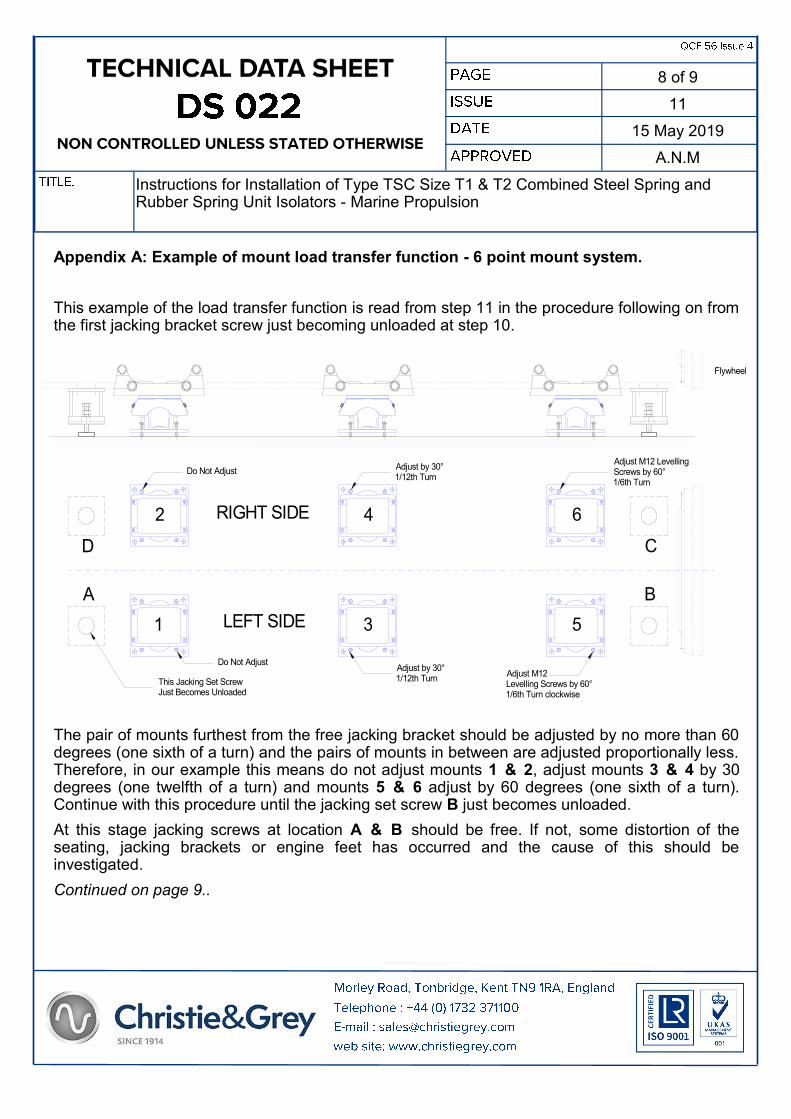
Appendix A: Example of mount load transfer function - 6 point mount system.
This example of the load transfer function is read from step 11 in the procedure following on from the first jacking bracket screw just becoming unloaded at step 10.
The pair of mounts furthest from the free jacking bracket should be adjusted by no more than 60 degrees (one sixth of a turn) and the pairs of mounts in between are adjusted proportionally less. Therefore, in our example this means do not adjust mounts 1 & 2, adjust mounts 3 & 4 by 30 degrees (one twelfth of a turn) and mounts 5 & 6 adjust by 60 degrees (one sixth of a turn). Continue with this procedure until the jacking set screw B just becomes unloaded.
At this stage jacking screws at location A & B should be free. If not, some distortion of the seating, jacking brackets or engine feet has occurred and the cause of this should be investigated.
Continued on page 9..
Do Not Adjust
D C
A B
1 3 5
642
LEFT SIDE
RIGHT SIDE
Adjust by 30°1/12th Turn
Adjust M12 LevellingScrews by 60°1/6th Turn
Flywheel
Do Not AdjustAdjust by 30°1/12th Turn
Adjust M12Levelling Screws by 60°1/6th Turn clockwise
This Jacking Set ScrewJust Becomes Unloaded

9 of 9
11
15 May 2019
A.N.M
Instructions for Installation of Type TSC Size T1 & T2 Combined Steel Spring and Rubber Spring Unit Isolators - Marine Propulsion
Appendix A: Example of mount load transfer function - 6 point mount system.
Continued from page 8..
At this stage jacking bracket screws at location A & B are both free.
Do not adjust the M12 levelling screws on the mounts located on the left side of the engine, that is mounts 1, 3 & 5 (jacking bracket screws unloaded), but screw down the levelling screws on the mounts located on the right hand side of the engine, mounts 2, 4 & 6, each by 30 degrees at a time (one twelfth of a turn) until the jacking bracket screws at locations C and D have just become unloaded.
At this point the load has successfully been transferred to the mounts.
Continue the procedure from step 12.
Please contact our Technical Department at the address below if you have any problems relating to installation.
30° or1/12th Turn
1
2
3
4
1
2
3
4
1
2
3
4
60° or1/6th Turn
Incremental rotation of levelling screws
D C
A B
1 3 5
642
LEFT SIDE
RIGHT SIDE
Adjust by 30°1/12th Turn
Do Not Adjust
This Jacking Set ScrewIs Just Unloaded
Adjust by 30°1/12th Turn
Adjust by 30°1/12th Turn
Do Not AdjustDo Not Adjust
This Jacking Set ScrewIs Just Unloaded