ma cvp kit instructions v1.0
DESCRIPTION
Manhattan Analog CVP (Control Voltage Processor) Module Kit Instructions(http://www.thonk.co.uk/shop/manhattan-analog-cvp-module-kit-copy/)TRANSCRIPT
May 5th 2013 www.thonk.co.uk 1
Manhattan Analog ʻCVPʼ Module
Eurorack DIY Kit Instructions Version 1.0
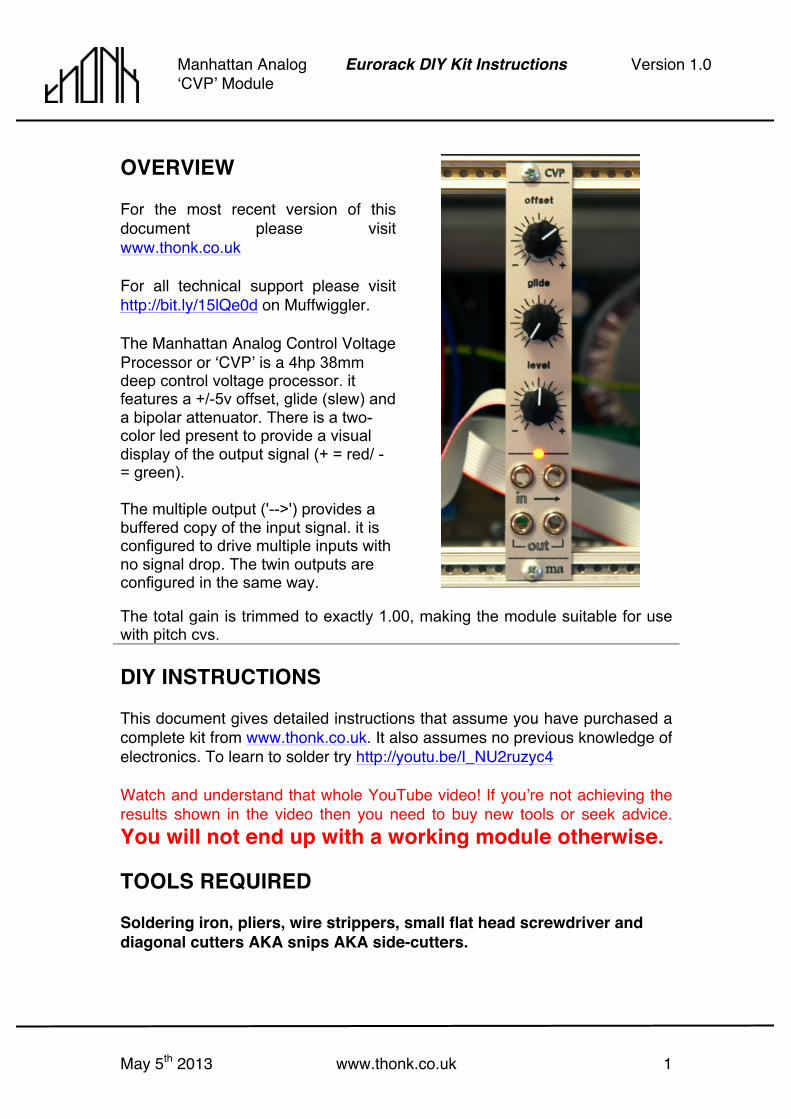
OVERVIEW For the most recent version of this document please visit www.thonk.co.uk For all technical support please visit http://bit.ly/15lQe0d on Muffwiggler. The Manhattan Analog Control Voltage Processor or ʻCVPʼ is a 4hp 38mm deep control voltage processor. it features a +/-5v offset, glide (slew) and a bipolar attenuator. There is a two-color led present to provide a visual display of the output signal (+ = red/ - = green). The multiple output ('-->') provides a buffered copy of the input signal. it is configured to drive multiple inputs with no signal drop. The twin outputs are configured in the same way.
The total gain is trimmed to exactly 1.00, making the module suitable for use with pitch cvs. DIY INSTRUCTIONS This document gives detailed instructions that assume you have purchased a complete kit from www.thonk.co.uk. It also assumes no previous knowledge of electronics. To learn to solder try http://youtu.be/I_NU2ruzyc4 Watch and understand that whole YouTube video! If youʼre not achieving the results shown in the video then you need to buy new tools or seek advice. You will not end up with a working module otherwise. TOOLS REQUIRED Soldering iron, pliers, wire strippers, small flat head screwdriver and diagonal cutters AKA snips AKA side-cutters.
May 5th 2013 www.thonk.co.uk 2
Manhattan Analog ʻCVPʼ Module
Eurorack DIY Kit Instructions Version 1.0
BILL OF MATERIALS
# inclʼ
Description Info
1 MA CVP Aluminium Panel 1 MA CVP PCB 1 Power Cable (10pin to 16pin) 3 Knobs
5 47k Resistor 2 470R Resistor 1 100k Resistor 1 4.7k Resistor 1 680R Resistor 1 39k Resistor 1 33k Resistor 2 Ferrite Bead
2 1N4001 diode In protective pink bag. Observe caution handling and follow general ESD precautions.
1 TL074 (Quad opamp) 1 LT1013 (Precision dual opamp)
2 PTC Resettable Fuse 2 .1uF Ceramic Capacitor 2 10uF Electrolytic Capacitor 1 1uF Elecrolytic Capacitor 1 10p Euro power header 4 16PJ138 Jacks 1 Bi-color/2-lead LED 1 20-25k Trimpot 1 1M Log Pot (A1M) 2 50k Lin (B50K) 4 24AWG stranded wire 2 M3 screws For mounting module in case. 1 IC socket 8 pin 1 IC socket 14 pin
I have provided roughly 50% more wire than you should require for a single build. However, do take care to use it efficiently.
May 5th 2013 www.thonk.co.uk 3
Manhattan Analog ʻCVPʼ Module
Eurorack DIY Kit Instructions Version 1.0
BUILD INSTRUCTIONS
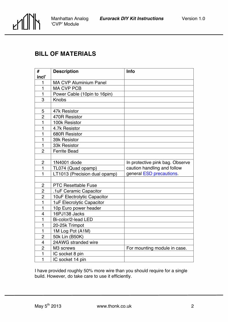
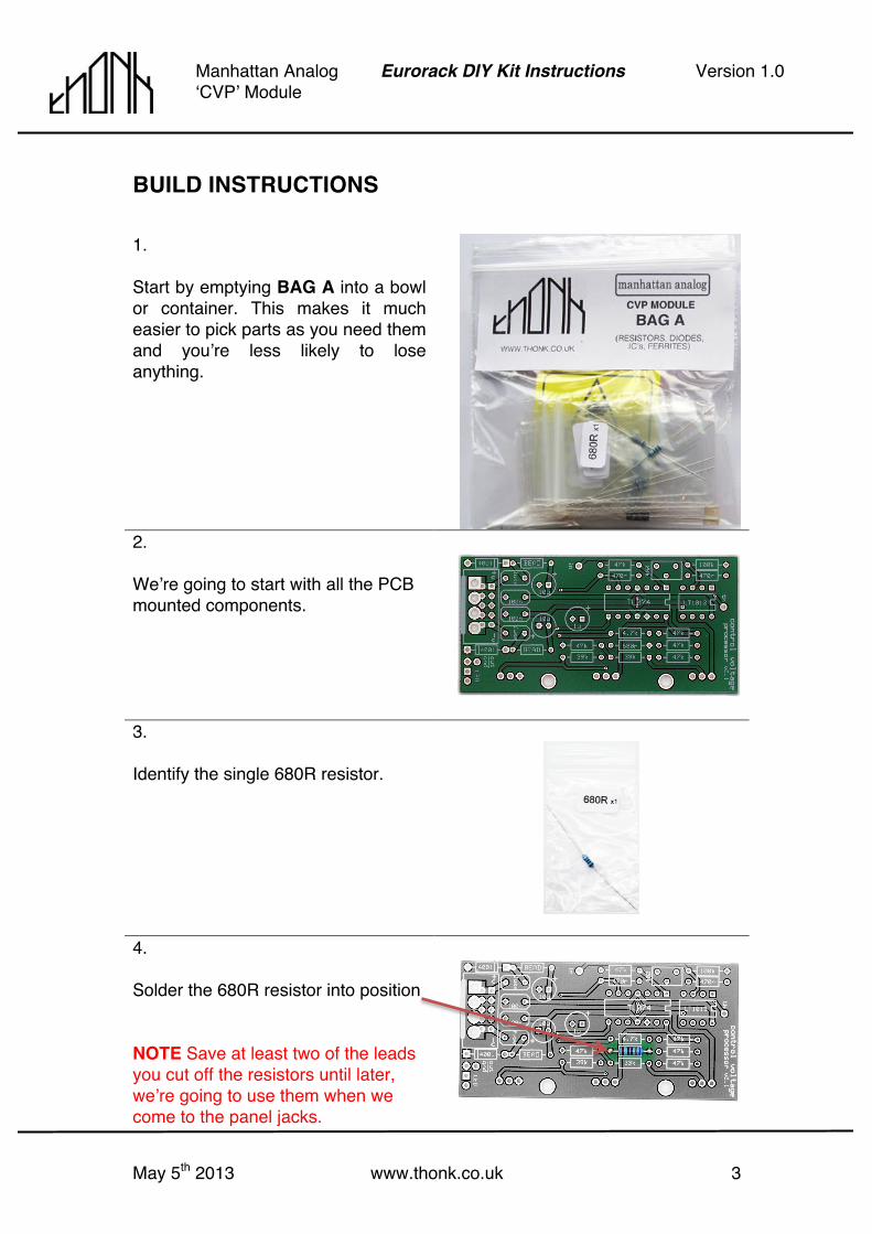
1. Start by emptying BAG A into a bowl or container. This makes it much easier to pick parts as you need them and youʼre less likely to lose anything. 2. Weʼre going to start with all the PCB mounted components.
3. Identify the single 680R resistor.
4. Solder the 680R resistor into position NOTE Save at least two of the leads you cut off the resistors until later, weʼre going to use them when we come to the panel jacks.
May 5th 2013 www.thonk.co.uk 4
Manhattan Analog ʻCVPʼ Module
Eurorack DIY Kit Instructions Version 1.0
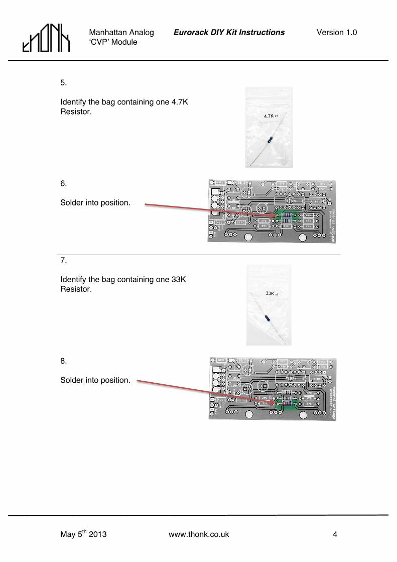
5. Identify the bag containing one 4.7K Resistor.
6. Solder into position.
7. Identify the bag containing one 33K Resistor.
8. Solder into position.

May 5th 2013 www.thonk.co.uk 5
Manhattan Analog ʻCVPʼ Module
Eurorack DIY Kit Instructions Version 1.0
9. Identify the bag containing one 39K Resistor.
10. Solder into position.
11. Identify the bag containing one 100K Resistor.
12. Solder into position.
May 5th 2013 www.thonk.co.uk 6
Manhattan Analog ʻCVPʼ Module
Eurorack DIY Kit Instructions Version 1.0
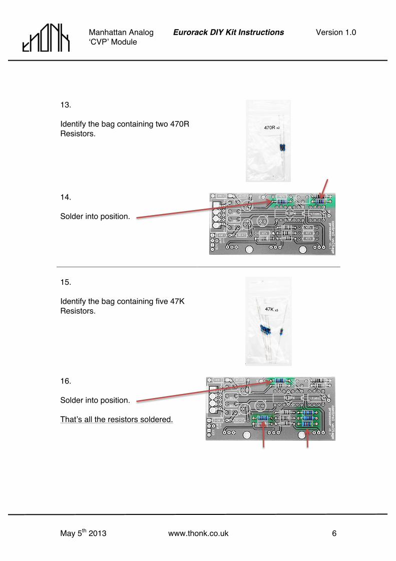
13. Identify the bag containing two 470R Resistors.
14. Solder into position.
15. Identify the bag containing five 47K Resistors.
16. Solder into position. Thatʼs all the resistors soldered.

May 5th 2013 www.thonk.co.uk 7
Manhattan Analog ʻCVPʼ Module
Eurorack DIY Kit Instructions Version 1.0
17. Remove the two Diodes from the protective ESD bag. Keep the two IC chips safely packed away for now. The IC chips should not be installed until right at the very end when the board is cool and all soldering is complete.
18. Solder Diodes into position. TAKE CARE itʼs vital you make sure they are orientated correctly. In the case of the particular diodes shown in the image, the silver stripe is aligned with the ʻboxedʼ end of the silkscreen. TAKE CARE Diodes can be damaged with excessive exposure to the soldering iron. Take care to not heat them for longer than 5 seconds if possible.
19. Identify the two ferrite beads, these are graphite/dark grey coloured with no markings. They are bigger than the diodes.
20. The Ferrites are soldered in the two BEAD positions alongside the diodes. You should now be finished with the contents of BAG A apart from the IC chips in the pink ESD bag.
May 5th 2013 www.thonk.co.uk 8
Manhattan Analog ʻCVPʼ Module
Eurorack DIY Kit Instructions Version 1.0
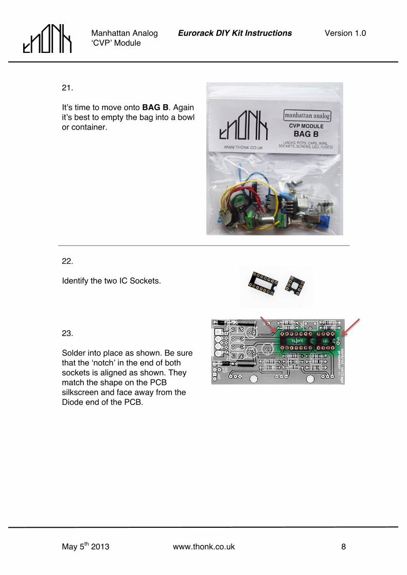
21. Itʼs time to move onto BAG B. Again itʼs best to empty the bag into a bowl or container.
22. Identify the two IC Sockets.
23. Solder into place as shown. Be sure that the ʻnotchʼ in the end of both sockets is aligned as shown. They match the shape on the PCB silkscreen and face away from the Diode end of the PCB.
May 5th 2013 www.thonk.co.uk 9
Manhattan Analog ʻCVPʼ Module
Eurorack DIY Kit Instructions Version 1.0
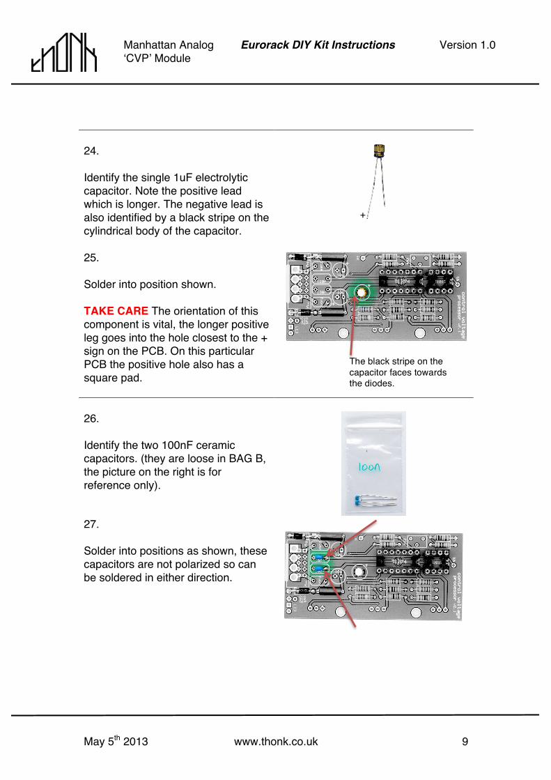
24. Identify the single 1uF electrolytic capacitor. Note the positive lead which is longer. The negative lead is also identified by a black stripe on the cylindrical body of the capacitor.
25. Solder into position shown. TAKE CARE The orientation of this component is vital, the longer positive leg goes into the hole closest to the + sign on the PCB. On this particular PCB the positive hole also has a square pad.
26. Identify the two 100nF ceramic capacitors. (they are loose in BAG B, the picture on the right is for reference only).
27. Solder into positions as shown, these capacitors are not polarized so can be soldered in either direction.
+
The black stripe on the capacitor faces towards the diodes.
May 5th 2013 www.thonk.co.uk 10
Manhattan Analog ʻCVPʼ Module
Eurorack DIY Kit Instructions Version 1.0
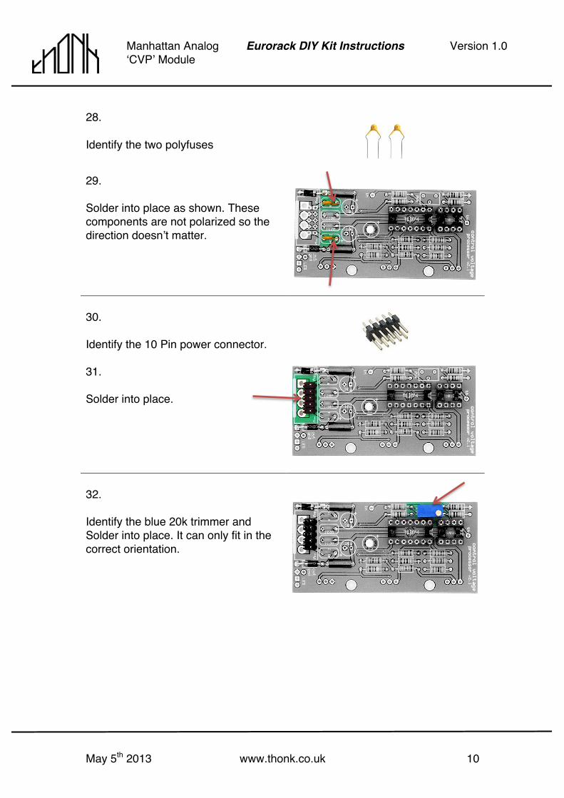
28. Identify the two polyfuses
29. Solder into place as shown. These components are not polarized so the direction doesnʼt matter.
30. Identify the 10 Pin power connector.
31. Solder into place.
32. Identify the blue 20k trimmer and Solder into place. It can only fit in the correct orientation.

May 5th 2013 www.thonk.co.uk 11
Manhattan Analog ʻCVPʼ Module
Eurorack DIY Kit Instructions Version 1.0
33. Next identify the two 10uF Electrolytic Capacitors. Note the positive lead which is longer. The negative lead is also identified by a black stripe on the cylindrical body of the capacitor.
34. Solder into place as shown. TAKE CARE The orientation of these components is vital, the longer positive leg goes into the hole closest to the + sign on the PCB. On this particular PCB the positive hole also has a square pad.
+ +
May 5th 2013 www.thonk.co.uk 12
Manhattan Analog ʻCVPʼ Module
Eurorack DIY Kit Instructions Version 1.0
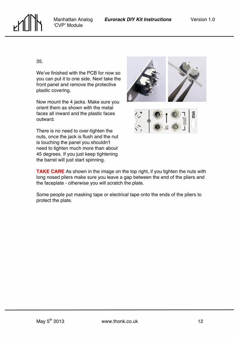
35. Weʼve finished with the PCB for now so you can put it to one side. Next take the front panel and remove the protective plastic covering. Now mount the 4 jacks. Make sure you orient them as shown with the metal faces all inward and the plastic faces outward. There is no need to over-tighten the nuts, once the jack is flush and the nut is touching the panel you shouldnʼt need to tighten much more than about 45 degrees. If you just keep tightening the barrel will just start spinning.
TAKE CARE As shown in the image on the top right, if you tighten the nuts with long nosed pliers make sure you leave a gap between the end of the pliers and the faceplate - otherwise you will scratch the plate. Some people put masking tape or electrical tape onto the ends of the pliers to protect the plate.
May 5th 2013 www.thonk.co.uk 13
Manhattan Analog ʻCVPʼ Module
Eurorack DIY Kit Instructions Version 1.0
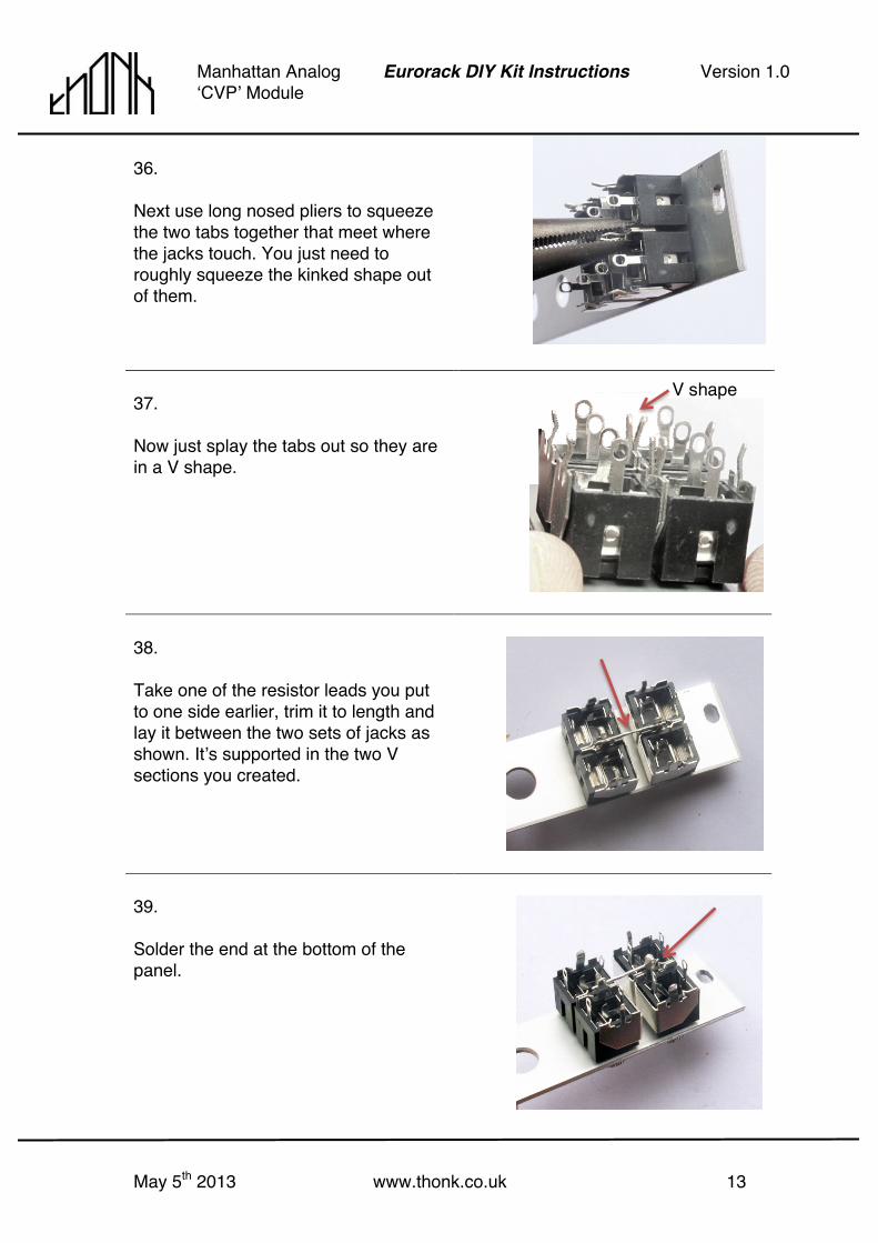
36. Next use long nosed pliers to squeeze the two tabs together that meet where the jacks touch. You just need to roughly squeeze the kinked shape out of them.
37. Now just splay the tabs out so they are in a V shape.
38. Take one of the resistor leads you put to one side earlier, trim it to length and lay it between the two sets of jacks as shown. Itʼs supported in the two V sections you created.
39. Solder the end at the bottom of the panel.
V shape

May 5th 2013 www.thonk.co.uk 14
Manhattan Analog ʻCVPʼ Module
Eurorack DIY Kit Instructions Version 1.0
40. Take the supplied black wire, strip one end, twist and tin with solder.
41. Solder the wire and other end of the repurposed resistor lead as shown. You now have a single wired ground connection for all four pins.
42. Put the front panel down and identify the three potentiometers. Remove the washers and nuts and put them to one side.
May 5th 2013 www.thonk.co.uk 15
Manhattan Analog ʻCVPʼ Module
Eurorack DIY Kit Instructions Version 1.0
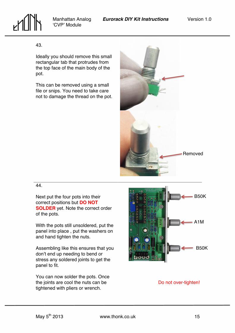
43. Ideally you should remove this small rectangular tab that protrudes from the top face of the main body of the pot. This can be removed using a small file or snips. You need to take care not to damage the thread on the pot.
44. Next put the four pots into their correct positions but DO NOT SOLDER yet. Note the correct order of the pots. With the pots still unsoldered, put the panel into place , put the washers on and hand tighten the nuts. Assembling like this ensures that you donʼt end up needing to bend or stress any soldered joints to get the panel to fit. You can now solder the pots. Once the joints are cool the nuts can be tightened with pliers or wrench.
Do not over-tighten!
B50K
A1M
B50K
Removed

May 5th 2013 www.thonk.co.uk 16
Manhattan Analog ʻCVPʼ Module
Eurorack DIY Kit Instructions Version 1.0
45. Next identify the LED and bend the longer lead (anode/positive) at a right angle as pictured.
46. Push this bent leg through the circular LED pad in the PCB. Push the LED into the hole in the front panel until it grips and holds itself in place. Solder this single leg.
47. Now bend the other leg through the Square LED pad. Make sure the LED is still positioned well in the front panel before soldering the second leg. NOTE It doesnʼt matter if you solder this LED the other way round, you wonʼt damage anything, the colours will simply be reversed. TAKE CARE The legs of the LED should not be touching!
May 5th 2013 www.thonk.co.uk 17
Manhattan Analog ʻCVPʼ Module
Eurorack DIY Kit Instructions Version 1.0
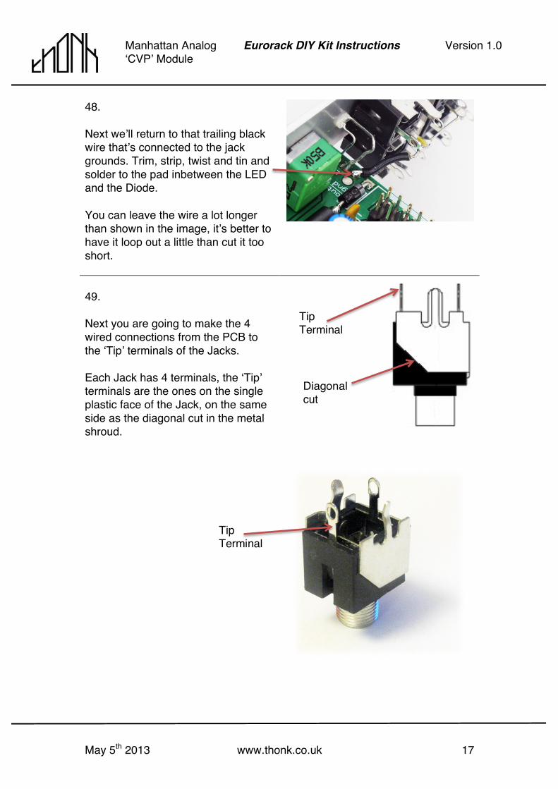
48. Next weʼll return to that trailing black wire thatʼs connected to the jack grounds. Trim, strip, twist and tin and solder to the pad inbetween the LED and the Diode. You can leave the wire a lot longer than shown in the image, itʼs better to have it loop out a little than cut it too short.
49. Next you are going to make the 4 wired connections from the PCB to the ʻTipʼ terminals of the Jacks. Each Jack has 4 terminals, the ʻTipʼ terminals are the ones on the single plastic face of the Jack, on the same side as the diagonal cut in the metal shroud.
Tip Terminal
Tip Terminal
Diagonal cut

May 5th 2013 www.thonk.co.uk 18
Manhattan Analog ʻCVPʼ Module
Eurorack DIY Kit Instructions Version 1.0
50. Take the blue wire. Strip, twist and tin one end and solder into the pad above the ʻgndʼ pad marked ʻoutʼ. Leave the wire full length for now.
51. Take another reserved resistor leg and bend one end into a hook as shown.
52. Hook through the two tip pins in the bottom two OUT jacks on the panel. Solder each end and cut off the excess.
53. Now cut the blue wire from the ʻoutʼ pad on the PCB to length and solder to the middle of the bridge you created in the previous step.
May 5th 2013 www.thonk.co.uk 19
Manhattan Analog ʻCVPʼ Module
Eurorack DIY Kit Instructions Version 1.0
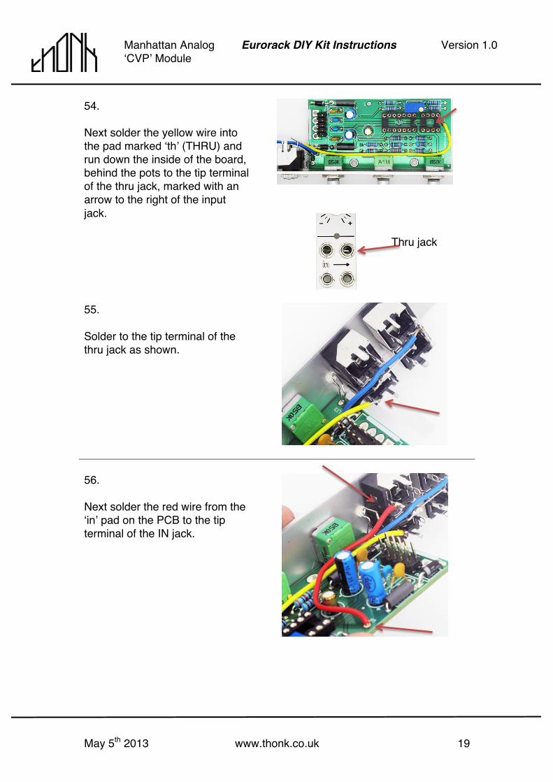
54. Next solder the yellow wire into the pad marked ʻthʼ (THRU) and run down the inside of the board, behind the pots to the tip terminal of the thru jack, marked with an arrow to the right of the input jack.
55. Solder to the tip terminal of the thru jack as shown.
56. Next solder the red wire from the ʻinʼ pad on the PCB to the tip terminal of the IN jack.
Thru jack
May 5th 2013 www.thonk.co.uk 20
Manhattan Analog ʻCVPʼ Module
Eurorack DIY Kit Instructions Version 1.0
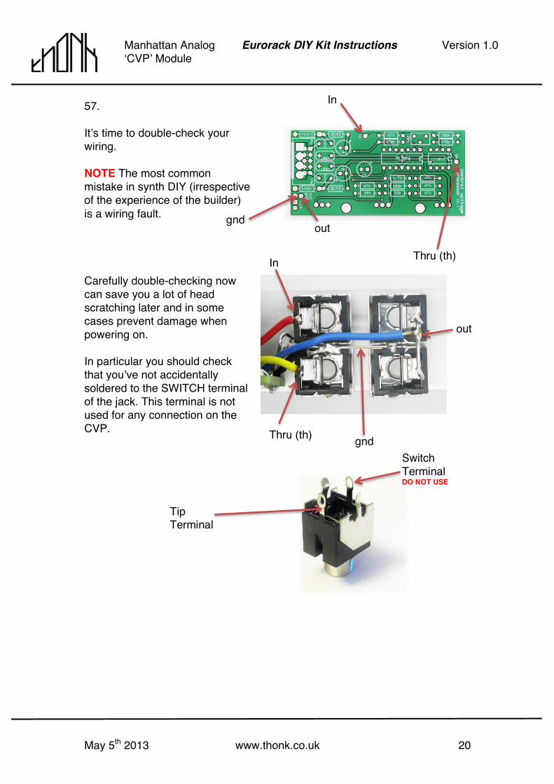
57. Itʼs time to double-check your wiring. NOTE The most common mistake in synth DIY (irrespective of the experience of the builder) is a wiring fault. Carefully double-checking now can save you a lot of head scratching later and in some cases prevent damage when powering on. In particular you should check that youʼve not accidentally soldered to the SWITCH terminal of the jack. This terminal is not used for any connection on the CVP.
Tip Terminal
Switch Terminal DO NOT USE
Thru (th)
In
out
gnd
In
out
Thru (th)
gnd

May 5th 2013 www.thonk.co.uk 21
Manhattan Analog ʻCVPʼ Module
Eurorack DIY Kit Instructions Version 1.0
58. Now grab the IC chips from the pink anti-static bag.
Observe normal ESD precautions. http://en.wikipedia.org/wiki/Electrostatic_discharge
59. The IC legs will be splayed out, you need them to be roughly perpendicular to the body. The safest way to do this is to just gently bend all 4 legs inwards with a pair of pliers. Legs perpendicular to body of IC
60. Install the ICs as shown. TAKE CARE Donʼt get them the wrong way round or you will probably destroy them on power up.

May 5th 2013 www.thonk.co.uk 22
Manhattan Analog ʻCVPʼ Module
Eurorack DIY Kit Instructions Version 1.0
61. TAKE CARE - Finally install the power cable, insuring the red stripe is as shown, matching the -12v labeling on the PCB that reads ʻ–Vʼ
62. Plug the module into your power busboard in your case (after powering your case OFF first naturally) Again make sure that the red stripe on the cable is aligned to the -12v or –V end of the header. TAKE CARE! Power on your case and you should now be ready to process CV…. THE END.
For technical support please use http://bit.ly/15lQe0d
on the Muffwiggler forum.