mac 6000 - generac mobile products - index · manual mac 6000 2106 east indiana ave., bismarck, nd...
TRANSCRIPT

MANUALMAC 6000
2106 East Indiana Ave., Bismarck, ND 58504 U.S.A. • www.macheaters.com • +1-800-272-4604

MAC 6000 Hydronic Heater
2106 East Indiana Ave., Bismarck, ND 58504 U.S.A. • www.macheaters.com • +1-800-272-4604
Pictures
7' 11"
6' 5 "
FRONT
4'
10' 11"
LEFT SIDE
15'
RIGHT SIDE
8'7"
1'
REAR
REV ECO ZONE DESCRIPTION DATE BY APPD
D
C
B
AA
B
C
D
45678
6 5 4 3 2 1
B3010001
X .1XX .04
XXX .010
CL
2106 East Indiana Avenue - Bismarck, ND 58504Office: 701-427-5831 - FAX 701-427-5531
www.macheaters.com
SolidWorks DATA
INTERPRET DRAWING PER ANSI Y14.5 - 1998
ANSI INCH
FRACTION: 1/16ANGLES: 1FILLETS / RADII .06
THIS PRINT, THE EXCLUSIVE PROPERTY OF MAC, Inc., IS CONFIDENTIAL, TO BE USED ONLY FOR THE PURPOSE FOR WHICH IT IS LOANED, RETURNED ON REQUEST, AND IS NOT TO BE
COPIED OR REPRODUCED WITHOUT WRITTEN PERMISSION.
DIMENSIONAL TOLERANCES UNLESS OTHERWISE SPECIFIED
DRAWN
DESIGNED
APPROVED
MAC, Inc.
PART NUMBER REV
WEIGHT: 289459324650869.19000000SCALE: 1:4
CL 4/29/2013
4/29/2013MAC 6000 Ground Heater
SHEET 1 OF 1
REF
FINISH:
MATERIAL: MILD STEEL
SURAFACE AREA:
THIRD ANGLEPROJECTION
3010001

MAC 6000 Hydronic Heater
2106 East Indiana Ave., Bismarck, ND 58504 U.S.A. • www.macheaters.com • +1-800-272-4604
Table of Contents
MAC 6000 - Specifications . . . . . . . . . . . . . . . . . . . . . . . . . . . . . . . . . . . . . . . . . . . . . . . . . . . . . . . . 1
MAC 6000 - Standard Features . . . . . . . . . . . . . . . . . . . . . . . . . . . . . . . . . . . . . . . . . . . . . . . . . . . . . 2
MAC 6000 - Options . . . . . . . . . . . . . . . . . . . . . . . . . . . . . . . . . . . . . . . . . . . . . . . . . . . . . . . . . . . . . 2
MAC 6000 - General Information . . . . . . . . . . . . . . . . . . . . . . . . . . . . . . . . . . . . . . . . . . . . . . . . . . . . 3
MAC, Inc. Warranty . . . . . . . . . . . . . . . . . . . . . . . . . . . . . . . . . . . . . . . . . . . . . . . . . . . . . . . . . . . . . . 4
General Trailering Information . . . . . . . . . . . . . . . . . . . . . . . . . . . . . . . . . . . . . . . . . . . . . . . . . . . . . . 6
Safe Trailer Towing Guidelines . . . . . . . . . . . . . . . . . . . . . . . . . . . . . . . . . . . . . . . . . . . . . . . . . . . . . . 7
Make regular stops to confirm . . . . . . . . . . . . . . . . . . . . . . . . . . . . . . . . . . . . . . . . . . . . . . . . . . . . . . 8
Wheel chock user guidelines . . . . . . . . . . . . . . . . . . . . . . . . . . . . . . . . . . . . . . . . . . . . . . . . . . . . . . . 8
Warnings and Cautions . . . . . . . . . . . . . . . . . . . . . . . . . . . . . . . . . . . . . . . . . . . . . . . . . . . . . . . . . . . 9
Informational Decals . . . . . . . . . . . . . . . . . . . . . . . . . . . . . . . . . . . . . . . . . . . . . . . . . . . . . . . . . . . . 12
Instructional Decals . . . . . . . . . . . . . . . . . . . . . . . . . . . . . . . . . . . . . . . . . . . . . . . . . . . . . . . . . . . . . 14
Warning Decals . . . . . . . . . . . . . . . . . . . . . . . . . . . . . . . . . . . . . . . . . . . . . . . . . . . . . . . . . . . . . . . . 16
Pre-Start Checklist . . . . . . . . . . . . . . . . . . . . . . . . . . . . . . . . . . . . . . . . . . . . . . . . . . . . . . . . . . . . . 19
Typical Hose Layout . . . . . . . . . . . . . . . . . . . . . . . . . . . . . . . . . . . . . . . . . . . . . . . . . . . . . . . . . . . . . 20
Start/Stop Procedure . . . . . . . . . . . . . . . . . . . . . . . . . . . . . . . . . . . . . . . . . . . . . . . . . . . . . . . . . . . . 22
Adjusting Heater Output . . . . . . . . . . . . . . . . . . . . . . . . . . . . . . . . . . . . . . . . . . . . . . . . . . . . . . . . . 23
Replacement Parts and Filters . . . . . . . . . . . . . . . . . . . . . . . . . . . . . . . . . . . . . . . . . . . . . . . . . . . . 24
Single Axle Parts - Trailer version . . . . . . . . . . . . . . . . . . . . . . . . . . . . . . . . . . . . . . . . . . . . . . . . . . 25
Isuzu Diesel Engine . . . . . . . . . . . . . . . . . . . . . . . . . . . . . . . . . . . . . . . . . . . . . . . . . . . . . . . . . . . . . 58
Generator . . . . . . . . . . . . . . . . . . . . . . . . . . . . . . . . . . . . . . . . . . . . . . . . . . . . . . . . . . . . . . . . . . . 123
Riello Burner . . . . . . . . . . . . . . . . . . . . . . . . . . . . . . . . . . . . . . . . . . . . . . . . . . . . . . . . . . . . . . . . . 150
Service and Maintenance Record . . . . . . . . . . . . . . . . . . . . . . . . . . . . . . . . . . . . . . . . . . . . . . . . . 167
Notes . . . . . . . . . . . . . . . . . . . . . . . . . . . . . . . . . . . . . . . . . . . . . . . . . . . . . . . . . . . . . . . . . . . . . . . 170
Quick Reference Service/Maintenance Guide . . . . . . . . . . . . . . . . . . . . . . . . . . . . . . . . . . . . . . . . 172

1 2106 East Indiana Ave., Bismarck, ND 58504 U.S.A. • www.macheaters.com • +1-800-272-4604
MAC 6000 Hydronic Heater
SpecificationsMAC 6000
2106 East Indiana Ave., Bismarck, ND 58504, U.S.A. www.macheaters.com +1.800.272.4604 Page 7
MAC 6000 – SPECIFICATIONS Imperial Metric
Heating Power Gross Input: 630,000 BTU/Hour 185 kW/Hour
Combustion Efficiency: 86% 86%
Engine/Genset(Isuzu): 10 hp/8 kW 7.46 kW/ 8 kW
Hose Length: 3,000 ft 6 x 500 ft
25 - 45 psi
915 m
172 - 310 kPa
1,500 GPH 5,678 LPH
225 US Gallons 852 Liters
4.5 GPH + 0.65 GPH 17 LPH + 2.46 LPH w/genset w/genset
65° - 185° F 18° - 85° C
186 IN x 96 IN x 92 IN 4,724 mm x 2,438 mm x 2,337 mm
3,466 kg (dry) 7,640 lbs (dry) 10,440 lbs (wet) 4,736 kg (wet) 2-5/16 IN Ball hitch coupler
Powder coat
Powder coat
Hose Pressure:
HTF Flow Rate:
Fuel Capacity:
Fuel Rate:
Operating Temperature:
Dimensions (L x W x H):
Weight:
Hitch (Trailer Mounted):
Finish-Interior
Finish-Exterior
Construction: Fabricated steel, fully enclosed, with forklift tubes and crane lifting points
Run Time:
Hose Rewind:
56 hrs @ 75% 78 hrs @ 50% AC motor
Fuel: #1 Diesel (below 32o F/0o C), #2 Diesel
Engine Controls: PLC based operation
Heat Transfer Fluid (HTF): Propylene Glycol - JEFFCOOL P155
6 x 153 m

22106 East Indiana Ave., Bismarck, ND 58504 U.S.A. • www.macheaters.com • +1-800-272-4604
MAC 6000 Hydronic Heater
Standard Features and Options
MAC 6000
2106 East Indiana Ave., Bismarck, ND 58504, U.S.A. www.macheaters.com +1.800.272.4604 Page 8
MAC 6000 - STANDARD FEATURESTrailer mounted-6,000 lb tandem leaf spring axles 16”, 6-Lug wheels and tires 2-5/16 IN Ball hitch-4 position adjustable height Electric trailer brakes Stop, turn and tail lights DOT Approved Lift jacks “D” Ring tie downs Engine Block Heater Secondary fluid containment, 110% containment Non-toxic HTF - Propylene glycol - JEFFCOOL P155 Low operating pressures Lockable access doors Powder coat finish Heavy gauge welded steel Fork lift tubes Crane lifting points LED lights in rear access door
MAC 6000 - OPTIONS Pintle hitch-4 position adjustable height-(optional trailer hitch) Spare tire and mount Custom paint colors Insulated curing/thawing blanketsEmergency stop Global Positioning System (GPS) Work light packages
Exterior LED work lights (flood or spot)Hazardous Environment Options
LEL Monitor – 75 harmful/explosive gas detection

3 2106 East Indiana Ave., Bismarck, ND 58504 U.S.A. • www.macheaters.com • +1-800-272-4604
General InformationMAC 6000 Hydronic Heater

4
MAC 6000 Hydronic Heater
2106 East Indiana Ave., Bismarck, ND 58504 U.S.A. • www.macheaters.com • +1-800-272-4604
Warranty
MAC 6000
2106 East Indiana Ave., Bismarck, ND 58504, U.S.A. www.macheaters.com +1.800.272.4604 Page 10
MAC, Inc. WARRANTY ONE (1) YEAR LIMITED WARRANTY MAC, Inc. warrants to the original purchaser of the equipment, that all workmanship and materials utilized in the construction of the equipment by MAC, Inc. will be free from substantial defects in material and workmanship for a period of one (1) year from the date of purchase. In addition to the above warranty, these components have an extended warranty period beyond one (1) year. Isuzu Engine 12 months*, unlimited hours**
100% Parts/100% Labor 12-24 months*, 200 hours** 100% Parts/100% Labor
* Whichever occurs first.** Coverage for all electrical, fuel system and turbocharger components is limited to 2yrs/1000 hours, whichever occurs first. Note: In the absence of a functional hour meter, the engine will be deemed to be in use for 8 hours per calendar day commencing from the start of the warranty period.
MeccAlte generator Two (2) years from delivery date to MAC, Inc. Rear Overhead door Two (2) years from shipment to customer
This warranty extends only to the original purchaser of MAC, Inc’s equipment and is not transferable to any other parties. MAC, Inc. does not assume responsibility for any promises, warranties, or representations beyond those expressed in the written document.
MAC, Inc.’s obligations and understandings in this warranty are limited to the repair or replacement, at its option, of any defective products manufactured by MAC, Inc, and in no event shall MAC, Inc. be liable for any consequential, indirect, or incidental costs or damages, including loss of use or any other damages of any type arising out of such defective parts or products.
Some States in the U.S.A. do not allow exclusion or limitation of incidental or consequential damages or implied warranties. In addition you may have other rights which vary from state to state. Any items of this warranty which conflict with the laws of our state are deemed amended by the law of your state.

5 2106 East Indiana Ave., Bismarck, ND 58504 U.S.A. • www.macheaters.com • +1-800-272-4604
Warranty (cont.)MAC 6000 Hydronic Heater
MAC 6000
2106 East Indiana Ave., Bismarck, ND 58504, U.S.A. www.macheaters.com +1.800.272.4604 Page 11
MAC, Inc. WARRANTY - (continued)
In the event that you believe any product manufactured by MAC, Inc. has a defect or malfunction or failure to conform to this written warranty, you should contact MAC, Inc. at its Bismarck, ND address:
MAC, Inc. 2106 East Indiana Ave. Bismarck, ND U.S.A. 58504 +1.800.272.4604 www.macheaters.com
Follow this procedure for warranty: 1. Contact MAC, Inc. at +1.800.272.46042. Ask to speak to a service representative3. Have the following information ready when you call
a. Original purchaser’s company nameb. Model number of your equipmentc. Serial number of your equipmentd. Purchase date of your equipment
4. Defective product may need to be returned to MAC, Inc. with the freight prepaid.Take appropriate precautions against damage during shipping.
5. Supply the following information with the returned producta. Name, address, contact person and telephone number of the original
purchaser of the equipment and indicate the date of purchase.b. Serial number and model number defective part is attached
MAC, Inc. will replace or repair any defective products within a reasonable period of time and return them to you. If MAC, Inc. determines there is no failure to this limited warranty, you will be notified to retrieve your product from the service facility. MAC, Inc. assumes no responsibility for merchandise not retrieved within thirty (30) days of notification to the original purchaser or owner of the product. This warranty has been drafted to comply with Federal legislation and rules promulgated by the Federal Trade Commission.
You have additional legal rights in addition to those set forth in this written limited warranty.

62106 East Indiana Ave., Bismarck, ND 58504 U.S.A. • www.macheaters.com • +1-800-272-4604
MAC 6000 Hydronic Heater
General Trailering InformationMAC 6000
2106 East Indiana Ave., Bismarck, ND 58504, U.S.A. www.macheaters.com +1.800.272.4604 Page 12
GENERAL TRAILERING INFORMATION
Driving a vehicle with a trailer in tow is vastly different from driving the samevehicle without a trailer in tow. It takes longer to get up to speed. You needmore room to turn and pass, and more distance to stop when towing a trailer.You are responsible for keeping your vehicle and trailer in control, and for alldamage that is caused if you lose control of your vehicle and trailer.
It is critical that the trailer be securely coupled to the hitch and that the safetychains are correctly attached. Uncoupling while towing may result in death orserious injury.
If the trailer comes loose from the hitch for any reason, we have provided safetychains so that control of the trailer can be maintained.
Your trailer is equipped with a breakaway brake system that will apply the brakeson your trailer if your trailer comes loose from the hitch. The safety chains andbreakaway brake system must be in good condition and properly rigged to beeffective. The breakaway brake system must not be used as a substitute for aparking brake or wheel chocking.
Be sure your hitch and tow vehicle are rated for the Gross Vehicle Weight Rating(GVWR) of your trailer.
Maximum towing speed 45 mph.
Be sure tires are inflated to pressure indicated on tire size and air pressure ID tagbefore towing. Improper inflation can result in a blowout and loss of control,which can lead to death or serious injury.
Be sure lug nuts are tight before each tow.
Be sure that the electric brakes and all of the lights on your trailer are functioningproperly before each tow.
Altering your trailer can damage essential safety items. DO NOT alter yourtrailer.

7 2106 East Indiana Ave., Bismarck, ND 58504 U.S.A. • www.macheaters.com • +1-800-272-4604
Safe Trailer Towing GuidelinesMAC 6000 Hydronic Heater
MAC 6000
2106 East Indiana Ave., Bismarck, ND 58504, U.S.A. www.macheaters.com +1.800.272.4604 Page 13
SAFE TRAILER TOWING GUIDELINES
Before towing, check coupling, safety chains, safety brake, tires, wheels and
lights.
Check the breakaway battery. Make sure it is fully charged.
Check the wheel lug nuts or bolts for tightness. 85-95 ft. /lbs.
Check coupler tightness after towing 50 miles (80km).
Adjust the brake controller to engage the trailer brakes before the tow vehicle
brakes.
Use your mirrors to verify that you have enough room to change lanes or pull into
traffic.
Use your turn signals well in advance.
Allow plenty of stopping distance for your trailer and tow vehicle.
Do not drive faster than the conditions will allow.
Allow plenty of room for passing. A rule of thumb is that passing distance with a
trailer is 4 times the passing distance without a trailer.
Use lower gears for climbing and descending grades.
Do not ride the brakes while descending grades; this can cause overheating and
potential brake failure.
Slow down for bumps in the road. Take your foot off the brake pedal when
crossing the bump.
Slow down prior to entering a curve; maintain a constant safe speed that allows
you to remain in control of your trailer. The towing vehicle will then remain in
control of the trailer.
Do not apply the tow vehicle brakes to correct extreme trailer swaying.
Continued pulling of the trailer, and even slight acceleration, or carefully applying
the trailer brakes (using the electronic brake controller) will provide a stabilizing
force.

8
MAC 6000 Hydronic Heater
2106 East Indiana Ave., Bismarck, ND 58504 U.S.A. • www.macheaters.com • +1-800-272-4604
Safe Trailer Towing Guidelines (cont.)MAC 6000
2106 East Indiana Ave., Bismarck, ND 58504, U.S.A. www.macheaters.com +1.800.272.4604 Page 14
SAFE TRAILER TOWING GUIDELINES – (continued)
Make regular stops to confirm
The coupler is secure to the hitch and is locked.
Electrical connections are made.
There is appropriate slack in the safety chains.
There is appropriate slack in the breakaway switch pull-pin cable.
The tires are inflated to proper air pressure and no damage or unusual wear to
tread or sidewalls.
The trailer and doors are secure, latched and in good condition.
Wheel chock user guidelines
Improper use may result in product failure.
Select wheel chock according to the equipment type and size.
Always use in pairs and on firm surfaces.
Chock in direction of grade.
Chock both sides of wheel if direction of grade is undetermined.
Use only after parking brake is applied and tested.
Center chocks snugly and squarely against tread of each wheel.
Always test chocks to insure they meet requirements.
Do not drive over wheel chocks.
For more trailering information check out: US Department of Transportation, National Highway Traffic Safety Administration website at:
http://www.nhtsa.gov/Cars/Problems/Equipment/towing/index.htm

9
MAC 6000 Hydronic Heater
2106 East Indiana Ave., Bismarck, ND 58504 U.S.A. • www.macheaters.com • +1-800-272-4604
Warnings and CautionsMAC 6000
2106 East Indiana Ave., Bismarck, ND 58504, U.S.A. www.macheaters.com +1.800.272.4604 Page 15
WARNINGS AND CAUTIONS The MAC 6000 Hydronic surface heater is designed and built for sustained reliable heat production in industrial, severe operating conditions and environments. The MAC 6000 is built to withstand rough and frequent handling. The sub-frame has forklift access at either side with crane lifting points on top for lifting and “D” ring tie-downs for transporting. The total enclosure design protects the operating components allowing all-weather storage or operations. All options incorporate integrated control and safety systems to insure reliable operations. MAC, Inc. offers training services to help you learn how to properly operate and maintain your unit. Contact MAC, Inc. at +1.800.272.4604
WARNINGS AND CAUTIONS LISTED IN THIS MANUAL MUST BE FOLLOWED!
REMEMBER SAFETY FIRST!! OPERATOR MUST READ AND UNDERSTAND ALL
OPERATING INSTRUCTIONS, WARNINGS, AND CAUTIONS BEFORE OPERATING HEATER.
WARNING! IMPROPER OPERATION OF THIS EQUIPMENT CAN CAUSE SERIOUS INJURY OR DEATH. READ OPERATION MANUAL SUPPLIED WITH THIS EQUIPMENT BEFORE OPERATING OR
SERVICING. DO NOT OPERATE WHILE TRANSPORTING. MAKE SURE UNIT IS PROPERLY SECURED WITH WHEEL CHOCKS AND ON LEVEL
GROUND TO PREVENT SHIFTING OR ROLLING. HEARING PROTECTION REQUIRED WHEN OPERATING THIS MACHINE. ADEQUATE AIRFLOW TO THE HEATER IS MANDATORY FOR SAFE RELIABLE
OPERATION. DO NOT COVER UNIT OR RESTRICT PROPER AIR FLOW. KEEP AIR INTAKE FREE AND CLEAR OF DEBRIS. HEATER SHOULD NOT BE LEFT UNATTENDED DURING OPERATION. SHUT ENGINE OFF BEFORE CHECKING FLUID LEVELS. ALL SAFETY GUARDS MUST BE IN PLACE DURING OPERATION. FOLLOW LOCKOUT PROCEDURE BEFORE SERVICING. MOVING PARTS CAN CRUSH AND CUT. HOT PRESSURIZED FLUID. DO NOT OPEN DOORS WHILE MACHINE IS RUNNING. DOORS MUST REMAIN CLOSED DURING OPERATION. JACKS ARE INTENDED FOR LEVELING AND STABILIZING ONLY. DURING OPERATION, INTERNAL COMPONENTS CAN BECOME BURN HAZARDS.
DO NOT TOUCH. ALLOW TIME TO COOL BEFORE SERVICING. FIRE FROM FLAMABLE FUEL CAN CAUSE SERIOUS INJURY OR DEATH. NO SMOKING, SPARKS OR OPEN FLAME DURING FUELING OR WASHDOWN. DO NOT ATTEMPT TO SERVICE ANY PART OF THIS MACHINE WHILE IN OPERATION. DO NOT ATTEMPT TO DISCONNECT OR REMOVE HOSES DURING OPERATION.
The MAC6000 operates at atmospheric pressure and is not a prssurized boiler. Boiler regulations do not apply to this product.
The MAC6000 operates at atmospheric pressure and is not considered a pressurized boiler. Boiler regulations do not apply to this product.

10
MAC 6000 Hydronic Heater
Lifting Instructions
2106 East Indiana Ave., Bismarck, ND 58504 U.S.A. • www.macheaters.com • +1-800-272-4604
• The MAC 6000 is equipped with crane lift points.
Never attempt to lift machine by any other points.
• Always use properly rated lifting equipment.
Lift points are only approved for use with a double leg sling.
• Always inspect lift points and lifting equipment for damage prior to lifting.
• Minimum sling-to-load angle is 60°.
• Select the appropriate lift point for most level lifting.
• Never attempt to lift the machine while in operation.
Crane Lifting Requirements
Crane Lifting Instructions
1. a.) To lift the machine using a double leg sling, attach one leg to each side
of the machine using the appropriate equipment (e.g. shackles, hooks).
b.) Select the appropriate lift eyes for balanced and level lifting.
2. Begin lifting the machine and verify the machine is stable and level.
Adjust lift eyes as necessary.
3. Lift the machine.

11
MAC 6000 Hydronic Heater
Notes
2106 East Indiana Ave., Bismarck, ND 58504 U.S.A. • www.macheaters.com • +1-800-272-4604

12
MAC 6000 Hydronic Heater
2106 East Indiana Ave., Bismarck, ND 58504 U.S.A. • www.macheaters.com • +1-800-272-4604
Informational Decals
MAC 6000
2106 East Indiana Ave., Bismarck, ND 58504, U.S.A. www.macheaters.com +1.800.272.4604 Page 16
INFORMATIONAL DECALS – Provide you important information about your MAC heater allowing for ease in servicing, ordering parts and/or warranty questions.
1 2 3 4 Located inside the right hand front control panel door
1 Serial #, Model # and VIN # ID tag
2 Tire size and air pressure ID tag
3 VIN #, Date of manufacture, GVWR, tire and rim size ID tag
4 MAC decal – To order parts call +1.800.272.4604 or www.macheaterparts.com
1
1 Model number decal – Located outside on the front right corner and the left rear corner of the heater.

13
MAC 6000 Hydronic Heater
2106 East Indiana Ave., Bismarck, ND 58504 U.S.A. • www.macheaters.com • +1-800-272-4604
Informational Decals (cont.)MAC 6000
2106 East Indiana Ave., Bismarck, ND 58504, U.S.A. www.macheaters.com +1.800.272.4604 Page 17
INFORMATIONAL DECALS – (continued)
1 2 3
1
Model number decal
2 Crane lifting points
3 Low or ultra-low sulfur DIESEL FUEL ONLY NO ADDITIVES
1 2 3 Located on the front trailer/heater tongue
1 Trailer/heater front lift jack
2
3
Tire size and air pressure ID tag
VIN #, date of manufacture, GVWR, tire and rim size ID tag

14
MAC 6000 Hydronic Heater
2106 East Indiana Ave., Bismarck, ND 58504 U.S.A. • www.macheaters.com • +1-800-272-4604
Instructional Decals
MAC 6000
2106 East Indiana Ave., Bismarck, ND 58504, U.S.A. www.macheaters.com +1.800.272.4604 Page 18
INSTRUCTIONAL DECALS – Provide important information to the operator on the proper operating requirements.
1 2 3
1 Crane lifting points
2 “D” ring tie downs during transportation Fork lift pockets
3 MAC Heaters – Engine/heater control panel

15
MAC 6000 Hydronic Heater
2106 East Indiana Ave., Bismarck, ND 58504 U.S.A. • www.macheaters.com • +1-800-272-4604
Instructional Decals (cont.)
MAC 6000
2106 East Indiana Ave., Bismarck, ND 58504, U.S.A. www.macheaters.com +1.800.272.4604 Page 19
INSTRUCTIONAL DECALS – (continued)
1 2 3 4
1 Notice – Do NOT operate while transporting
2 Doors must be closed during operation
3 Notice – Keep air intake free and clear of debris
4 Caution: Hot Exhaust – Both engine and burner

16
MAC 6000 Hydronic Heater
2106 East Indiana Ave., Bismarck, ND 58504 U.S.A. • www.macheaters.com • +1-800-272-4604
Warning Decals
MAC 6000
2106 East Indiana Ave., Bismarck, ND 58504, U.S.A. www.macheaters.com +1.800.272.4604 Page 20
WARNING DECALS – Provide important information and warnings to ensure the safety of the operator and the machine.
1 2 3
1 WARNING – Improper operation of this equipment can cause serious injury or death. Read operation and maintenance manual and safety manual supplied with this equipment before operating or servicing.
2 WARNING – Wheel Lugnuts May Become Loose Tighten wheel lugnuts to factory specifications after first 50 miles. Retighten periodically thereafter.
3 WARNING – Burn Hazard. Do NOT touch. Allow to cool before servicing. During operation, internal components are a burn hazard.

17
MAC 6000 Hydronic Heater
2106 East Indiana Ave., Bismarck, ND 58504 U.S.A. • www.macheaters.com • +1-800-272-4604
Warning Decals (cont.)MAC 6000
2106 East Indiana Ave., Bismarck, ND 58504, U.S.A. www.macheaters.com +1.800.272.4604 Page 21
WARNING DECALS - (continued)
1 2 3 4 5 1 Doors must be closed during operation
2 WARNING – Burn Hazard. Do NOT touch. Allow to cool before servicing. During operation, internal components are a burn hazard.
3 Notice – Keep air intake free and clear of debris
4 CAUTION: HOT EXHAUST – Both engine and burner
5 WARNING – Fire from flammable fuel can cause serious injury or death. No smoking, sparks or open flame during fueling or wash-down.

18
MAC 6000 Hydronic Heater
2106 East Indiana Ave., Bismarck, ND 58504 U.S.A. • www.macheaters.com • +1-800-272-4604
Warning Decals (cont.)MAC 6000
2106 East Indiana Ave., Bismarck, ND 58504, U.S.A. www.macheaters.com +1.800.272.4604 Page 22
WARNING DECALS - (continued)
1 1 3 1 1 2 1 1 WARNING – Burn Hazard. Do NOT touch. Allow to cool before servicing.
During operation, internal components are a burn hazard.
2 DANGER – Moving parts can crush and cut. Do not operate with guard
removed. Follow lock out procedure before servicing.
3. WARNING – Moving parts can crush and cut. Keep hands clear while operating
machine.
For questions or more information, please contact: MAC, Inc. 2106 East Indiana Avenue Bismarck, ND 58504 U.S.A. +1.800.272.4604

19
MAC 6000 Hydronic Heater
2106 East Indiana Ave., Bismarck, ND 58504 U.S.A. • www.macheaters.com • +1-800-272-4604
Pre-Start ChecklistMAC 6000
2106 East Indiana Ave., Bismarck, ND 58504, U.S.A. www.macheaters.com +1.800.272.4604 Page 23
PRE-START CHECKLIST
WARNING! SEVERE INJURY MAY RESULT IF PRECAUTIONS ARE NOT FOLLOWED. DO NOT COVER THE MACHINE. MACHINE MUST BE USED IN AN OPEN
AREA. DO NOT OPERATE MACHINE WITH ACCESS DOORS OPEN. MACHINE MUST BE COMPLETELY SHUT DOWN BEFORE OPENING
ACCESS DOORS. MAKE SURE ENGINE IS SHUT OFF BEFORE CHECKING FLUID LEVELS. MACHINE MUST BE RUN ON LEVEL GROUND TO INSURE PROPER
OPERATION. MACHINE MUST BE SECURED ON LEVEL GROUND TO PREVENT
ROLLING OR SHIFTING AS SERIOUS INJURY MAY OCCUR.WARNING!
Do not use any fuel other than diesel #1 or diesel #2 Do not use gasoline or ANY fuel contaminated with gasoline!
PRE-START CHECKLIST Check area surrounding heater for flammable materials or fire hazards. Check exterior of heater for any fluid leaks. (Fuel, engine oil, engine antifreeze,
glycol hose leaks) Check general condition of heater. Check air intake screens for any obstructions and are in proper condition. Check exhaust stacks for any obstruction. (snow, ice, etc..) Insure ground hose is securely fastened to outlet assembly. Check to see that unit has been serviced and ready for operation. Check fuel tank for proper fuel and fuel level. Only diesel fuel #1 or #2*ATTN: MAKE SURE DIESEL HAS NO ADDITIVES* Check that the unit is level and properly secure before starting. Hook up ground hoses in desired configuration.
ENGINE COMPARTMENT CHECKLIST Check interior compartment for fluid leaks. (Fuel-engine/burner, engine oil,
engine antifreeze, glycol tank/hoses/tube lines) Check all filters for leaks and are in proper working condition. Check all fluid levels prior to starting machine. (Fuel, engine oil, engine
antifreeze, glycol tank) Check battery and battery cables are secure and in good condition. Check fuel lines and electrical cables and connections for damage and security. Check glycol lines and fittings for leaks, cracks and overall condition. Check engine belts and hoses for overall condition. Check engine control panel for security. Fuel supply and return valves in “Open” position.

20
MAC 6000 Hydronic Heater
Typical Hose Layout
2106 East Indiana Ave., Bismarck, ND 58504 U.S.A. • www.macheaters.com • +1-800-272-4604
MAC 6000Heater
DIMENSION
D
THAW SPACING
12 IN - 18 IN
CURE SPACING
18 IN - 24 IN

21
MAC 6000 Hydronic Heater
Notes
2106 East Indiana Ave., Bismarck, ND 58504 U.S.A. • www.macheaters.com • +1-800-272-4604

22
MAC 6000 Hydronic Heater
2106 East Indiana Ave., Bismarck, ND 58504 U.S.A. • www.macheaters.com • +1-800-272-4604
Start/Stop Procedure
MAC 6000
2106 East Indiana Ave., Bismarck, ND 58504, U.S.A. www.macheaters.com +1.800.272.4604 Page 24
START/STOP PROCEDURE
3 4 6 Engine/Heater Control Panel
START PROCEDURE 1. Perform pre-start and engine compartment checklists.2. Hook up and layout your ground hoses in desired configuration.3. Turn battery disconnect connect switch to “ON” position.4. Turn ignition key to “Run” position until glow plug indicator light expires.5. Turn ignition key to “Start” position until engine starts, then release ignitionkey. 6. Turn main circuit breaker to “ON” position, located on the power distributionpanel. 7. Select heater performance output.
a. Select desired output temperature on the heater controller by using theup and down arrow keys.
b. Press “OK” button to engage heater.c. Heater will automatically enter a “Warm Up” mode.d. Once “Warm Up” mode has been completed heater will function
normally.STOP PROCEDURE
1. Press “OK” button on controller to shutdown heater.a. Failure to shutdown heater before turning off generator could result indamage to the heater.
2. Turn main circuit breaker to “OFF” position.3. Turn ignition key to “OFF” position.4. Caution: Allow hot ground hoses to cool before handling and preparing forstorage. Hot ground hoses can cause severe burns.

23
MAC 6000 Hydronic Heater
2106 East Indiana Ave., Bismarck, ND 58504 U.S.A. • www.macheaters.com • +1-800-272-4604
Adjusting Heater Output
MAC 6000
2106 East Indiana Ave., Bismarck, ND 58504, U.S.A. www.macheaters.com +1.800.272.4604 Page 25
ADJUSTING HEATER OUTPUT
1 2 1 2
Heater Main Menu
SETTING/ADJUSTING HEATER 1. Press Up and Down arrow keys for desired temperature setting.2. Press “OK” button once you have set your desired temperature to engageheater. 3. Heater will automatically enter a “Warm Up” mode.4. Once “Warm Up” mode has been completed heater will function normally.
SHUTTING DOWN HEATER 1. Press “OK” button on controller to shutdown heater.
a. Failure to shutdown heater before turning off generator could result indamage to the heater.
2. Turn main circuit breaker to “OFF” position.3. Turn ignition key to “OFF” position.4. Caution: Allow hot ground hoses to cool before handling and preparing forstorage. Hot ground hoses can cause severe burns. The controls allow the operator to efficiently balance the heat output to meet the requirements of the application.
The improved controls integration allows the operator to efficiently balance the heat and flow output.

24
MAC 6000 Hydronic Heater
2106 East Indiana Ave., Bismarck, ND 58504 U.S.A. • www.macheaters.com • +1-800-272-4604
Replacement Parts and Filters
MAC 6000
2106 East Indiana Ave., Bismarck, ND 58504, U.S.A. www.macheaters.com +1.800.272.4604 Page 26
REPLACEMENT PARTS AND FILTERS Battery Part # MAC Isuzu Engine Fuel Filter Part # MAC Isuzu Engine Oil Filter Part # MAC Isuzu Engine Air Filter Part # MAC Isuzu Engine Oil Part # MAC Riello burner? Nozzles? Burner filter? All Isuzu engine filters to comply with warranty
Description MAC Part #
Battery MAC2013
Isuzu Engine Fuel Filter 3020578
Isuzu Engine Oil Filter 3020577
Isuzu Engine Air Filter 3020579
Burner Nozzle MAC1611
Burner Fuel Filter MAC0576
Use only Isuzu engine filters to comply with warranty

25
MAC 6000 Hydronic Heater
Trailer Axle Manual
2106 East Indiana Ave., Bismarck, ND 58504 U.S.A. • www.macheaters.com • +1-800-272-4604
Trailer Axle Manual
T A
Owner's Manual

26
MAC 6000 Hydronic Heater
Trailer Axle Manual
2106 East Indiana Ave., Bismarck, ND 58504 U.S.A. • www.macheaters.com • +1-800-272-4604
Trailer Axle Manual
3
Rev: 07.25.2013
INTRODUCTION
Combining years of experience in the trailer frame and recreational vehicle industry with the newest and most innovative technology, Lippert Components, Inc. introduces it’s newest addition, The Axle and Running Gear Division.
The following publication is designed to give the customer an easy-to-understand operation and service manual to provide useful and important information. The quality of the Lippert name and the finest materials utilized in the production of the Axles and Running Gear provide you with hubs, brakes, drums and spindles that make trailering and braking the finest in the industry.
Quality comes threefold in Lippert Components, Inc.
1. The finest quality materials
2. The latest technology and design
3. The quality standards maintained from materials to final assembly
All three points provide the customer with the best product they can possibly buy and the satisfaction of knowing they can trust the equipment on which they have spent their hard-earned money.
Lippert Components, Inc. thanks you for purchasing our Axles and Running Gear. When you speak of Lippert Components, Inc., our quality stands beside you.
SAFETY INFORMATION
The “WARNING” symbol above is a sign that a service or maintenance procedure has a safety risk involved and may cause serious injury or death if not performed safely and within the parameters set forth in this manual.
Always wear eye protection when performing service or maintenance to the vehicle. Other safety equipment to consider would be hearing protection, gloves and possibly a full face shield, depending on the nature of the service.
This manual provides general service and maintenance procedures. Many variables can change the circumstances of the service procedure, i.e., the degree of difficulty involved in the service operation and the ability level of the individual performing the operation. This manual cannot begin to plot out procedures for every possibility, but will provide the general instructions for effectively servicing the vehicle. In the event the skill level required or the procedure to difficult, a certified technician should be consulted before performing the necessary service. Failure to correctly service the vehicle may result in voiding the warranty, inflicting injury or even death.
The owner’s manual for your unit may have more procedures for service and maintenance.
Introduction/Safety Information

27
MAC 6000 Hydronic Heater
Trailer Axle Manual
2106 East Indiana Ave., Bismarck, ND 58504 U.S.A. • www.macheaters.com • +1-800-272-4604
4
Rev: 07.25.2013
BREAK-IN PERIOD FOR ELECTRIC DRUM BRAKES
The break-in period is a typical phenomenon with drum brakes and especially electric drum brakes. Electric drum brakes will require a break-in period to achieve full performance. This break-in period applies for new axles and any time new brake shoes and/or magnets are installed as part of regular maintenance.
Lippert Components has found through extensive brake testing that the break-in period for our drum brakes can range from 20 to 50 brake applications.
Brakes can be seated in by applying approximately 8-10 volts to the trailer brakes at an initial speed of 40 mph and allowing the truck/trailer combination to slow down to 20 or 25 mph. For best results do not use truck brakes during this procedure. The trailer brakes will seat in faster by using them to stop both the truck and trailer. The easiest method is to apply the trailer brakes using the manual activation lever located on the in-cab brake controller. Care must be taken to not overheat the lining material, therefore brake applications conducted at one mile intervals will suffice. The driver should feel a noticeable difference in the brake performance during this period, sometimes in as few as 10 applications. After 50 applications, the brake lining material will be fully cured from the heat and develop close to 100% contact with the brake drum surface.
This break in period not only seats the shoe lining material but also seats in the brake electromagnets. During the break-in period, the linings will wear at a faster rate than they do after they are seated in.
NOTE: Brakes should be manually adjusted after the first 200 miles of operation and periodically thereafter, approx. 3,000 mile intervals.
HUBS/DRUMS/BEARINGS
HUB REMOVAL
To remove the hub assembly for inspection, maintenance or service, follow the six (6) steps below:
Lift unit by the frame and never the axle or suspension. Do not go under unit unless it is properly supported by jack stands. Unsupported units can fall causing
serious injury or death.
1. Lift trailer and support it per manufacturer’s requirements.
2. Remove the wheel.
3. Remove the grease cap by prying the edge out of the hub. If equipped with oil lubrication, unscrew oil cap using a 2 1/2” socket, let oil drain into pan.
4. Pull the cotter pin from the castle nut and remove the outer spindle nut.
5. Remove the spindle washer.
6. Pull the hub off the spindle. Do not let the outer bearing cone fall free of the assembly. The inner bearing cone will be contained by the seal and will not fall out.
NOTE: Brakes may need to be adjusted or backed off to remove drum from spindle.
NOTE: A gear puller may be necessary to remove hub from spindle.
Brak
es/H
ubs/
Dru
ms/
Bear
ings

28
MAC 6000 Hydronic Heater
Trailer Axle Manual
2106 East Indiana Ave., Bismarck, ND 58504 U.S.A. • www.macheaters.com • +1-800-272-4604
5
Rev: 07.25.2013
BRAKE DRUM INSPECTION
The brake shoes contact the drum surface and the magnet contacts the armature. These surfaces are subject to wear and should be inspected periodically.
The drum surface should be re-machined if wear is more than .030” or out of round by more than .015”. The drum should be replaced if scoring or wear is greater than .090”.
The inner surface of the brake drum that contacts the brake magnet is the armature surface. If the armature surface is scored or worn unevenly, it should not be machined more than .030”. The magnets should be replaced whenever the armature surface is refaced and vice versa.
NOTE: Make certain that the wheel bearing cavities are clean and free of contamination before reinstalling bearing and seals. Resurfacing procedures can produce metal chips and dust that can contaminate the wheel bearings and cause failure.
Drum Maximum Rebore Diameter
12.25" 12.340"
BEARING INSPECTION
Wash all grease and oil from the bearing cone using a suitable solvent. Dry the bearing with a clean, lint-free cloth and inspect each roller completely. If any pitting, spalling, or corrosion is present, then the bearing must be replaced. The bearing cup inside the hub must be inspected.
NOTE: Bearings must always be replaced in sets of one cone and one cup.
Always wear eye protection when servicing the axle, brakes, hubs, springs and wheels. Failure to wear eye protection may result in serious injury.
Follow the procedure below to replace the bearing cup:
1. Place hub on a flat surface with bearing cup on the bottom.
2. With brass drift punch, lightly tap around the small end of the cup to push it out.
3. Clean the hub bore. Replace the cup by tapping it back in with the brass drift punch. Cup should be seated against the retaining shoulder in the hub.
Consult Bearing Replacement Chart for proper replacement bearings.
NOTE: Replacing the bearing cup is a very precise process. The cup must be perfectly seated when replaced. If the cup is not seated correctly, damage to the assembly may not be covered by the warranty. Consult Lippert Components, Inc. prior to replacing bearing and bearing cup. The trailer should be taken to a certified service center for this work to be done.
Do not mix Lithium, calcium, sodium or barium complex greases. Chemical compatibility problems may occur. If you are changing from one chemical grease
to another, be sure all old grease is removed prior to applying new grease.
BEARING LUBRICATION - OIL
If your axles are equipped with oil lubricated hubs, then your lubrication procedure is to periodically fill the hub with a high quality hypoid gear oil to the level indicated on the clear plastic oil cap. The oil can be filled through the rubber plug hole in the cap.
Bearing Inspection and Lubrication-Oil

29
MAC 6000 Hydronic Heater
Trailer Axle Manual
2106 East Indiana Ave., Bismarck, ND 58504 U.S.A. • www.macheaters.com • +1-800-272-4604
Trailer Axle Manual
6
Rev: 07.25.2013
BEARING LUBRICATION - GREASE
Bearing grease should be replaced every 12,000 miles or 12 months, whichever comes first. Remove all old grease from wheel hub and bearings first. Bearings should be packed by machine if possible. Packing bearings by machine is preferable; however, packing by hand is a viable alternative.
Follow these procedures to repack bearings by hand:
1. Place grease into the palm of your hand (Fig. 1).
2. Press widest end of bearing into the outer edge of the grease pile, forcing grease into the inner area of the bearing between two adjacent rollers (Fig. 2).
3. Repeat this process while turning bearing from roller to roller until all rollers are coated.
4. Apply a light coat of grease into the bearing cup surface.
5. Reassemble bearing into cup.
Fig. 1 Fig. 2
Recommended Wheel Bearing Grease Specifications
Thickener Type Lithium Complex
Dropping Point 230°C (446°F) Minimum
Consistency NLGI No. 2
Additives EP, Corrosion, & Oxidation Inhibitors
Base Oil Solvent Refined Petroleum Oil
Base Oil Viscosity @40°C (104°F) 150cSt (695 SUS) Minimum
Viscosity Index 80 Minimum
Pour Point -10°C (14°F) Minimum
Approved Sources
Mobil Oil Mobilgrease HP
Exxon/Standard Ronex MP
Kendall Refining Co. Kendall L-427
Ashland Oil Co. Valvoline Val-plex EP Grease
Pennzoil Prod. Co. Premium Wheel Bearing Grease 707L
Bear
ing
Lubr
icat
ion
- Gre
ase

30
MAC 6000 Hydronic Heater
Trailer Axle Manual
2106 East Indiana Ave., Bismarck, ND 58504 U.S.A. • www.macheaters.com • +1-800-272-4604
Trailer Axle Manual
7
Rev: 07.25.2013
SEAL INSPECTION AND REPLACEMENT
Always check the seal to make sure that it is not damaged, nicked, cracked or torn and is in good working order. If there is any question of condition, replace the seal.
Procedure to replace seal:
1. Pull seal from the hub with a seal puller. Never push the seal out with the bearing. The bearing may get damaged.
2. Apply a PERMATEX sealant to the outside of the new seal.
NOTE: Do not use PERMATEX on rubber encased seals.
3. Tap the new seal into place using a clean, hard wood block (Fig. 3).
NOTE: When installing a new oil seal, be sure side marked “AIR SIDE” is away from bearing cone.
Fig. 3
BEARING ADJUSTMENT/HUB REPLACEMENT
To adjust bearings or replace removed hub, follow procedures below:
1. Place hub, bearing, washers and castle nut back on axle spindle in the reverse order from which they were removed. Castle nut should be torqued to 50 ft.-lb. Hub will rotate during this process.
2. Loosen castle nut to back off the torque.
3. Tighten castle nut finger tight until snug.
4. Insert cotter pin. If cotter pin does not line up with hole, back castle nut up slightly until pin can be inserted (Fig. 4).
5. Bend cotter pin over to lock nut in place. Nut should be free to move with only the cotter pin keeping it in place.
Fig. 4
Seal Inspection and Replacement
Bearing Adjustm
ent and Hub Replacem
ent

31
MAC 6000 Hydronic Heater
Trailer Axle Manual
2106 East Indiana Ave., Bismarck, ND 58504 U.S.A. • www.macheaters.com • +1-800-272-4604
8
Rev: 07.25.2013
ELECTRIC BRAKES
The basic structure of the Electric Brakes on your trailer will resemble the brakes on your car or tow vehicle, with one major difference; your trailer implements an Electric Actuation system and your tow vehicle utilizes a hydraulic system. The Electric Braking System operates in the following order of steps; refer to the Electric Braking System Diagram and the brake diagram (Fig. 5) to follow along:
1. Electric current is supplied to the trailer’s braking system when the tow vehicle’s brakes are applied.
2. From the tow vehicle’s battery, the electricity flows to the brake’s electromagnet.
3. When energized the magnets are attracted to the rotating surface of the drums.
4. This moves the actuating levers in the direction the drums are turning.
5. The actuating cam at the end of the shoe forces the primary shoe out to the drum surface.
6. The force of the primary shoe actuates the secondary shoe to contact the drum.
7. The force applied to the brake drum can be increased by elevating the current flow to the magnet.
Fig. 5
A
B
C D
E
F
G Callout Component
A Primary Shoe
B Actuating Lever
C Adjuster
D Magnet
E Adjusting Spring
F Secondary Shoe
G Retracting Spring
HOW TO USE LIPPERT ELECTRIC BRAKES PROPERLY
The Lippert Components, Inc. Electric Braking System is synchronized with the tow vehicle brakes. Never attempt to stop the combined load of the tow vehicle and the trailer by using either the tow vehicle brakes or the trailer brakes only. They are designed to work together.
Small manual adjustments may occasionally be necessary to accommodate changing loads and driving conditions. Synchronization of tow vehicle to trailer braking can only be accomplished by road testing. Locking up, excessive grab, or delayed application is quite often due to the lack of synchronization between the tow vehicle and the trailer being towed. High voltage (2V+), Low voltage (2V-) or improperly adjusted brakes are the most common causes of these problems and can be easily remedied.
Prior to any adjustments, your trailer brakes should be burnished-in by applying the brakes 20-30 times with a 20 m.p.h. decrease in speed, e.g. 40 m.p.h. to 20 m.p.h. Allow ample time for brakes to cool between application. This allows the brake shoes and magnets to begin seating to the brake drum.
Elec
tric
Bra
kes

32
MAC 6000 Hydronic Heater
Trailer Axle Manual
2106 East Indiana Ave., Bismarck, ND 58504 U.S.A. • www.macheaters.com • +1-800-272-4604
9
Rev: 07.25.2013
Trailer Wire Gauge Chart
Wire Gauge and Type Number of Axles Length of Run
16 Ga Stranded Copper 1 N/A
14 Ga Stranded Copper 2 Under 30ft. (9.1m) from hitch to center of axles
12 Ga Stranded Copper 2 or 3 Over 30ft. (9.1m) from hitch to center of axles
GENERAL MAINTENANCE - ELECTRIC BRAKES
BRAKE ADJUSTMENT
Prior to testing or adjusting brakes, be sure area is clear of any persons and vehicles. Failure to perform test in a clear area may result in serious injury or
death.
Lippert Components, Inc. Electric Brakes are automatic adjust only. If manual adjusting is needed, the following 6-step procedure can be utilized. The brakes should be adjusted in the following manner:
1. Jack up trailer and secure on adequate capacity jack stands. Follow trailer manufacturer’s recommendations for lifting and supporting the unit. Make sure the wheel and drum rotates freely.
Lift unit by frame and never the axle or suspension. Do not go under unit unless it is properly supported by jack stands. Unsupported units can fall causing
serious injury or death.
2. Remove the adjusting hole cover from the adjusting slot on the bottom of the brake backing plate.
3. With a screwdriver or standard adjusting tool, rotate the starwheel of the adjuster assembly to expand the brake shoes. Adjust the brake shoes out until the pressure of the linings against the drum makes the wheel very difficult to turn.
4. Then rotate the starwheel in the opposite direction until the wheel turns freely with a slight lining drag.
NOTE: A second screwdriver will be needed to push the auto adjusting lever away from the adjuster starwheel so that the starwheel can be rotated backwards.
5. Replace the adjusting hole cover and lower the wheel to the ground.
6. Repeat the above procedure on all brakes. For best results, the brakes should all be set at the same clearance.
LUBRICATE BRAKES
Prior to reassembling the brake drum assembly, remember to apply a light film of white grease or an anti-seize compound on the brake anchor pin, the actuating arm bushing and pin, and the areas on the backing plate that are in contact with the brake shoes and magnet lever arm. In addition apply a light film of grease on the actuating block mounted on the actuating arm.
Electric Brake Maintenance

33
MAC 6000 Hydronic Heater
Trailer Axle Manual
2106 East Indiana Ave., Bismarck, ND 58504 U.S.A. • www.macheaters.com • +1-800-272-4604
10
Rev: 07.25.2013
CLEAN AND INSPECT BRAKES
In the event the braking system encounters symptoms of improper application or failure, immediate inspection and service must be implemented. During normal use, servicing the braking system once a year is considered normal. Increased usage will require service on a regulated schedule based on 3000-6000 mile increments. As magnets and shoes become worn, they need to be changed to maintain maximum braking capability.
Be sure, when disassembling brakes for cleaning, to clean the backing plate, magnet arm, magnet and shoes. Also, make sure that any and all parts removed for cleaning are placed back into the same brake drum assembly. This is also an excellent time to check for parts that have become loose or worn.
Potential Asbestos Dust Hazard
Older brake linings have the potential to contain asbestos dust, which has been linked to serious or fatal illnesses. Certain precautions must be taken when servicing brakes:
1. Avoid creating and/or breathing any brake dust.
2. Do not machine, file, or grind the brake linings.
3. Remove with a damp brush or cloth. Dry brushing or compressed air will cause the dust particles to become airborne.
MAGNETS
This electric braking system utilizes an electromagnet to actuate the brake shoes. These high-quality magnets provide superior force and friction to safely and effectively stop the trailer. These magnets should be inspected and serviced on the same schedule as the rest of the axle system, at east once a year for normal use and more often if the trailer is used extensively. Abnormal or uneven wear is a sign that the magnet needs to be replaced. Check the surface of the magnet with a straight edge to check for uneven wear. The surface of the magnet should be completely flat.
If the magnet’s coil is exposed in any way, even if normal wear is evident, the magnets should be replaced immediately. If the electromagnets are replaced, the drum armature surface should also be refaced. If a magnet is replaced on one side of an axle, it is recommended that the magnet on the opposite brake assembly also be replaced to ensure even braking capacity.
Figure 6, below, shows an Electro-Magnet with little or no wear. If there are any pronounced gaps on the surface of the Electro-Magnet, the magnet should be replaced.
Fig. 6
Elec
tric
Bra
ke M
aint
enan
ce

34
MAC 6000 Hydronic Heater
Trailer Axle Manual
2106 East Indiana Ave., Bismarck, ND 58504 U.S.A. • www.macheaters.com • +1-800-272-4604
11
Rev: 07.25.2013
SHOES AND LININGS
Linings should be replaced if the material is worn to 1/16” or less. Shoes should also be replaced if they become contaminated with grease or oil or have become scored, pitted or gouged. Heat cracks are normal and rarely require attention. When replacing shoes, both shoes on the same brake and the brakes on the same axle should all be replaced at the same time, once again ensuring even braking capacity.
After replacing shoes and linings, your trailer brakes should be burnished-in by applying the brakes 20-30 times with a 20 m.p.h. decrease in speed, e.g. 40 m.p.h. to 20 m.p.h. Allow ample time for brakes to cool between application. This allows the brake shoes and magnets to begin seating to the brake drum.
AXLE AND SUSPENSION INSTALLATION
The single most important portion of axle installation is parallel alignment of the trailer axle(s) to the tow vehicle or drive axle(s). Parallel installation allows for correct and safe control, prolonged tread life and will all but eliminate dog-tracking. Proper alignment is most readily achieved by measuring from the center of the trailer king pin to the center of each end of the axles.
Lippert Components, Inc. tubular axles are made of high strength steel to prevent metal fatigue and provide the best possible welding conditions. The round tubular axles allow for even and uniform structure.
Always wear eye protection when servicing the axle, brakes, hubs, springs and wheels. Failure to wear eye protection may result in serious injury.
SUSPENSION SYSTEMS
The suspension systems incorporated into Lippert Component, Inc. axles are designed to provide the following benefits:
1. Attach the axle to the trailer.
2. Dampen the effects of road shock.
3. Provide stability to the trailer.
All Lippert suspension systems are available in single and multiple axle configurations. For specific or custom applications, please contact Lippert Components, Inc. Axle Division.
DOUBLE-EYE LEAF SPRINGS
Double-eye leaf springs have eyes at either end of the spring assembly with nylon bushings to assist in preventing wear. U-bolts hold the springs to the axle with a plate.
The articulation of this suspension occurs when the eyes rotate on the wear surfaces provided in eyes of the springs and on the equalizers. This suspension is also available in single and multiple axle configurations.
In trailers with 2 or more axles, the additional movement is maintained by an equalizer. This feature allows for even load handling from axle to axle.
Double eye suspension systems are available on 8,000 lb. axles. Tandem and triple axle mounting kits are available for both 33” and 35” axle spacing.
Axles and Suspension System
s

35
MAC 6000 Hydronic Heater
Trailer Axle Manual
2106 East Indiana Ave., Bismarck, ND 58504 U.S.A. • www.macheaters.com • +1-800-272-4604
12
Rev: 07.25.2013
TORSION SUSPENSION SYSTEM
1. The Lippert Components, Inc. Torsion Suspension system is designed to offer superior qualities over leaf spring technology. The Lippert Components, Inc. Torsion Suspension system is bracketed to the trailer’s frame and housed inside the trailer axle’s tube.
2. The spindle is connected to a swing arm, the swing arm is connected to a square inner bar that is sheathed in rubber and as the swing arm rotates and experiences the torque and resistance of driving conditions, the characteristics of the rubber absorb and distribute the load providing benefit over leaf spring suspensions.
3. The Lippert Components, Inc. Torsion Suspension system requires very little attention in regards to maintenance. Normal inspection of the entire Lippert Components, Inc. Trailer Axle system can be applied to the Torsion Suspension system. See inspection procedures for system components in this manual.
Fig.7
Front Hanger
Shackle Link
Center Hanger
Rear Hanger
Shackle Bolts
EqualizerTie Plate
Spring Axle Torque Specifications
Bolt Type Axle Capacity Maximum Torque
U-Bolts
2K 25 ft-lb
3.5K with ½ " 50 ft-lb
5.2K 65 ft-lb.
6-8K 90 ft-lb.
Minimum Torque Maximum Torque
Shackle Bolts 30 ft-lb 50 ft-lb
Elec
tric
Bra
ke M
aint
enan
ce

36
MAC 6000 Hydronic Heater
Trailer Axle Manual
2106 East Indiana Ave., Bismarck, ND 58504 U.S.A. • www.macheaters.com • +1-800-272-4604
13
Rev: 07.25.2013
Torsion Axle Torque Specifications
Axle Size Bolt Size Torque Range
#8 - #9 1/2" 70-90 ft-lb.
#10 - #13 5/8" 120-155 ft-lb.
Washer(s) must be placed against the slotted hole in the axle bracket
NOTE: Low profile brackets have plain round holes
Fig. 8
Outside Frame
Outside bracket dimension
NOTE: For Torsion installation, mount axle bracket to frame bracket (Fig. 8) and torque fasteners as specified in the chart below.
INSPECTION
All the components of your suspension system should be visually inspected for signs of wear, damage or loose fasteners at least every 6,000 miles. When replacing or tightening loose fasteners, consult the torque specs on page 16 for correct torque values.
Worn spring eye bushings or sagging or broken springs should be replaced using the following method:
1. Support the trailer with the wheels just off the ground. Follow the trailer manufacturer’s recommendations for lifting and supporting the unit.
2. After the unit is properly supported place a suitable block under the axle tube near the end to be repaired. This block is to support the weight of the axle only so that suspension components can be serviced or replaced.
3. Disassemble the U-bolts, nuts, and tie plates.
4. Remove the spring eye bolts and the spring.
5. If the spring eye bushings are to be replaced, press out the old bushing by hand or tapping out with a punch.
6. Free-floating nylon bushing needs no lubrication. Press the new bushing into the spring eye by hand or gently tapping it in with a bounceless rubber or plastic mallet.
7. Reinstall repaired or replaced components in reverse order.
NOTE: For multiple axle units, the weight of each axle must be supported as outlined in Step 2 before disassembly of any component of the suspension system.
Axles and Suspension System
s

37
MAC 6000 Hydronic Heater
Trailer Axle Manual
2106 East Indiana Ave., Bismarck, ND 58504 U.S.A. • www.macheaters.com • +1-800-272-4604
14
Rev: 07.25.2013
Lift unit by the frame and never the axle or suspension. Do not go under unit unless it is properly supported by jack stands. Unsupported units can fall causing serious injury or death.
Always wear eye protection when servicing the axle, brakes, hubs, springs and wheels. Failure to wear eye protection may result in
serious injury.
If the equalizer or equalizer bushings must be replaced, follow the instructions above for lifting and supporting the trailer unit and then proceed as follows:
1. With both axles blocked up, remove the spring eyebolt, keeper bolt, and equalizer bolt from the equalizer to be repaired or replaced.
2. Press the old nylon bushing out of the equalizer.
3. Reassemble in reverse order.
SUSPENSION REPLACEMENT
1. Make sure springs are on straight. Align spring eyes to front hanger. Insert spring eye bolts but do not torque at this point.
2. Assemble springs into equalizer.
3. After leveling equalizer to frame, torque equalizer nuts and spring eye nuts to a minimum of 55 ft.-lb. and a maximum of 70 ft-lb.
WHEELS
WHEEL SELECTION
When specifying or replacing your trailer wheels it is important that the wheels, tires, and axle are properly matched. The following characteristics are extremely important and should be thoroughly checked when replacement wheels are considered:
1. Bolt Circle. Wheels have many bolt circle variations and some are so close that it could be possible to attach an inappropriate wheel that does not match the axle hub.
2. Capacity. Wheel load capacity should match tire and trailer max. load ratings.
3. Offset. The relationship of the center line of the tire to the hub face of the axle should match any replacement. Failure to match offset may result in reducing the carrying capacity of your axle.
4. Rim Contour. Replacement wheels should be direct replacements to match the rim contour.
Use only rim contours suggested by manufacturer. Failure to use correct rim contour may cause dramatic separation of tire and wheel and could cause serious
injury or death.
Attempting to modify or repair a wheel can cause unsafe conditions that may result in an explosion. Air pressure on a weakened or cracked rim can cause
serious injury or death.
Elec
tric
Bra
ke M
aint
enan
ce

38
MAC 6000 Hydronic Heater
Trailer Axle Manual
2106 East Indiana Ave., Bismarck, ND 58504 U.S.A. • www.macheaters.com • +1-800-272-4604
15
Rev: 07.25.2013
TORQUE REQUIREMENTS
It is extremely important to apply and maintain proper wheel mounting torque on your trailer axle. Torque wrenches assure the proper amount of torque is being applied to a fastener. Use no other method to torque fasteners.
Proper and accurate torque must be maintained to prevent wheels from loosening, studs from cracking and/or breaking or other possible hazardous breakage resulting
in serious injury or death.
Be sure to use only the fasteners matched to the cone angle of your wheel (usually 60°or 90°.) The proper procedure for attaching your wheels is as follows:
1. Start all bolts or nuts by hand to prevent cross threading.
2. Tighten bolts or nuts in the following sequence.
3. Tightening fasteners should be done in stages. Follow the recommended sequence, tighten fasteners per wheel torque requirements diagram (Fig. 9).
4. Wheel nuts/bolts should be torqued before first road use and after each wheel removal. Check and re-torque after the 10 and 25 miles and again at 50 miles. A periodic check during regular service is recommended.
Wheel Torque Requirement Chart
Wheel Size Stud Size
Torque Sequence
!st Stage 2nd Stage 3rd Stage
14" 1/2" 20-25 ft-lbs 50-60 ft-lbs 90-120 ft-lbs
15" 1/2" 20-25 ft-lbs 50-60 ft-lbs 90-120 ft-lbs
16" 1/2" 20-25 ft-lbs 50-60 ft-lbs 90-120 ft-lbs
16.5" x 6.75" 1/2" 20-25 ft-lbs 50-60 ft-lbs 90-120 ft-lbs
16" 9/16" 20-25 ft-lbs 60-70 ft-lbs 120-130 ft-lbs
16.5" x 6.75" 9/16" 20-25 ft-lbs 60-70 ft-lbs 120-130 ft-lbs
17.5" Long Nut 5/8" 50-60 ft-lbs 100-120 ft-lbs 190-210 ft-lbs
17.5" Flange Nut 5/8" 50-60 ft-lbs 150-200 ft-lbs 275-325 ft-lbs
14.5" Demount 5/8" Tighten sequentially to 85-95 ft-lbs
Fig. 9
11
2 5
4 31
3
24 5
61 3
24 5
6
87
Fig. 10
Axles and Suspension System
s

39
MAC 6000 Hydronic Heater
Trailer Axle Manual
2106 East Indiana Ave., Bismarck, ND 58504 U.S.A. • www.macheaters.com • +1-800-272-4604
16
Rev: 07.25.2013
TIRES
Prior to mounting tires onto wheels, be sure the rim size and contour are approved by the Tire and Rim Association Yearbook or the tire manufacturers catalog. In addition, confirm that the tire will carry the rated load. If the load is not evenly distributed on all tires,use the tire rated for the heaviest wheel position.
The Rubber Manufacturers Association or the tire manufacturers guidelines should be consulted for mounting procedures.
Tire inflation pressure is the most important factor in tire life. Tire pressure should always be what is recommended by the manufacturer for the load. Always check pressure cold before operation. DO NOT bleed air from tires when they are hot. Check inflation pressure weekly during use to insure maximum tire and tread life.
The following tire wear diagnostic chart will help you pinpoint the causes and solutions of tire wear problems.
NOTE: Tire wear should be checked frequently because once a wear pattern becomes firmly established in a tire it is difficult to stop, even if the underlying cause is corrected.
Probable Cause Corrective Action
Center Wear Over-inflation
Adjust Pressure to particular load per tire
catalog
Edge Wear Under-inflationAdjust pressure to
particular load per tire catalog.
Side Wear Loss of camber or overloading
Make sure load doesn't exceed axle rating. Call Lippert Service
& Warranty to advise.
Toe Wear Incorrect Toe-in Call Lippert Service & Warranty to advise.
Cupping Out-of-BalanceCheck bearing
adjustment and balance tires.
Flat Spots Wheel lockup & tire skidding
Avoid Sudden stops if possible and adjust
brakes.
Tire
s
Fig. 10

40
MAC 6000 Hydronic Heater
Trailer Axle Manual
2106 East Indiana Ave., Bismarck, ND 58504 U.S.A. • www.macheaters.com • +1-800-272-4604
17
Rev: 07.25.2013
INTRODUCTION TO TROUBLESHOOTING
The following section is a guideline for ensuring operation of your braking system. The safety of you, those traveling with you and those sharing the road paramount and it starts with the ability to safely stop the tow vehicle and the towed vehicle.
TROUBLESHOOTING
Most brake malfunctions can be corrected by utilizing the Troubleshooting Chart on the next page. Mechanical failure is the most common form of malfunction, however, if the brake system fails and it’s not mechanical, it is usually electrical. A Voltmeter and Ammeter are essential tools to diagnose these problems.
Mechanical problems are mostly self-evident; something is bent or broken. Consult the following troubleshooting chart to determine the probable cause and corrective actions for a variety of issues with the braking system.
Please remember to use only Lippert Components, Inc. replacement parts on these systems. Consult the Limited Warranty or call our Service Department for any other related issues.
MEASURING VOLTAGE
The Braking System voltage is measured at the two lead wires of the magnet on any brake. Use the pin probes inserted through the insulation of the lead wires. To ensure that the battery is indicating a full charge, the towing vehicle engine should be running with the trailer coupler connected when checking the voltage.
Voltage in the system should begin at 0 volts and, as the brake pedal of the tow vehicle is applied, voltage will gradually increase to about 12 volts. If the system does not indicate at least 12 volts, problems may occur in the wiring of the system, the battery or alternator of the tow vehicle.
When the brakes are applied, a gradual increase in voltage is preferable to a quick increase to 12 volts. A gradual increase in voltage ensures smooth and firm trailer braking. A quick increase in voltage will cause the braking system to feel like the trailer is grabbing too quickly.
Taking a Voltage reading is usually done with probes inserted into the wire connector (Fig. 11).
Troubleshooting - Introduction
Fig. 11

41
MAC 6000 Hydronic Heater
Trailer Axle Manual
2106 East Indiana Ave., Bismarck, ND 58504 U.S.A. • www.macheaters.com • +1-800-272-4604
18
Rev: 07.25.2013
NO BRAKES
Open Circuits Find & Correct
Short Circuits Test & Correct
Severe Underadjustment Adjust Brakes
WEAK BRAKES
Grease or Oil on Magnets or Linings Clean or Replace
Corroded Connections Clean & Correct Cause of Corrosion
Worn Linings or Magnets Replace
Scored or Grooved Brake Drums Machine or Replace
Improper Synchronization Correct
Underadjustment Adjust Brakes
Glazed Linings Reburnish or Replace
LOCKING BRAKES
Underadjustment Adjust
Improper Synchronization Correct
Loose, Bent, or Broken Brake Components Test & Correct
Out-of-Round Brake Drums Machine or Replace
Isufficient Wheel Load Adjust System Resistor and Synchronize
INTERMITTENT BRAKES
Broken Wires Test and Correct
Loose Connections Repair or Replace
Faulty Ground Find and Repair
BRAKES PULL TO ONE SIDE
Wrong Magnet Lead Wire Color Adjust
Incorrect Adjustment Correct
Grease or Oil on Linings or Magnets Clean or Replace
Broken Wires Find and Repair
Bad Connections Find and Repair
HARSH BRAKES
Underadjustment Adjust
Improper Synchronization Correct
NOISY BRAKES
Underadjustment Adjust
Lack of Lubrication Lubricate
Broken Replace Component
Incorrect Brake Components Correct
Table continued on page 19.
Trou
bles
hoot
ing
- Cha
rt

42
MAC 6000 Hydronic Heater
Trailer Axle Manual
2106 East Indiana Ave., Bismarck, ND 58504 U.S.A. • www.macheaters.com • +1-800-272-4604
19
Rev: 07.25.2013
SURGING BRAKES
Grease or Oil on Linings or Magnet Clean or Replace
Out of Round or Cracked Brake Drums Machine or Replace
DRAGGING BAKES
Overadjustment Readjust
Out-of-Round Brake Drums Machine or Replace
Incorrect Brake Components Replace
Loose, Bent, or Broken Brake Components Replace
Faulty Breakaway Switch Repair or Replace
Loose Wheel Bearing Adjustment Adjust
Bent Spindle Replace Axle
NOTE: If all trailer lights and brakes do not work, check your wiring plug connection and make sure the ball is making solid contact with the coupler (that is how a trailer is grounded). Too much grease or not using dielectric grease on the ball and coupler can cause this to happen.
MEASURING AMPERAGE
The Braking System amperage is the amount of current flowing through the system when all magnets have been energized. The amperage will change proportionately with the voltage. To ensure that the battery is indicating a full charge, the towing vehicle engine should be running with the trailer coupler connected when checking the voltage.
If a resistor is used in the brake system, it must be set at zero or bypassed completely to obtain the maximum amperage reading. Individual amperage draw can be measured by inserting the ammeter in the line at the magnet you want to check. Disconnect one of the magnet lead wire connectors and attach the ammeter between the two wires. Consult Amperage Chart on the next page for normal amp readings.
Make sure that the wires are properly reconnected and sealed after testing is completed.
Testing for Amperage can be done with probes (Fig. 12) or alligator clips on the leads or an amp clamp (Fig. 13).
Troubleshooting - Am
perage
Fig. 12 Fig. 13

43
MAC 6000 Hydronic Heater
Trailer Axle Manual
2106 East Indiana Ave., Bismarck, ND 58504 U.S.A. • www.macheaters.com • +1-800-272-4604
20
Rev: 07.25.2013
AMPERAGE CHART
Low or no voltage are the most common problem with the Braking System. Amperage at the brakes is also a relatively common issue. Common causes of these conditions are:
1. Low quality electrical connections
2. Open circuits
3. Insufficient wire gauge
4. Broken wires
5. Blown fuses (fusing of brakes is not recommended)
6. Short circuits (indicated by high amperage)
Possible causes of shorts are:
1. Shorted magnet coils
2. Bare wires contacting a grounded object
Finding the cause of a short circuit in the system is done by isolating one section at a time. If the high amperage reading drops to zero by unplugging the trailer, then the short is in the trailer. If the amperage reading remains high with all the brake magnets disconnected, the short is in the trailer wiring.
Amps/ Magnet
Two Brakes
Four Brakes Six Brakes
3.0 6.0 12.0 18.0
All electrical troubleshooting procedures should start at the controller. Most complaints regarding brake harshness or malfunction are traceable to improperly adjusted or nonfunctional controllers. See your controller manufacturer’s data for proper adjustment and testing procedures. For best results, all the connection points in the brake wiring should be sealed to prevent corrosion. Loose or corroded connectors will cause an increase in resistance which reduces the voltage available for the brake magnets.
Ampe
rage
Cha
rt

44
MAC 6000 Hydronic Heater
Trailer Axle Manual
2106 East Indiana Ave., Bismarck, ND 58504 U.S.A. • www.macheaters.com • +1-800-272-4604
21
Rev: 07.25.2013
Maintenance Schedule
Item Function Required Weekly 3 Months/3000 Miles
6 Months/6000 Miles
12 Months/12000 Miles
Brakes Test that they're operational. At Every Use
Breakaway System
Check battery charge and switch operation. At Every Use
Brake Adjustment
Adjust to proper operating clearance.
Brake Magnets Inspect for wear and current draw.
Brake Linings Inspect for wear or contamination.
Brake ControllerCheck for correct amperage and modulation.
Trailer Brake Wiring
Inspect wiring for bare spots, fray, etc.
Hub/Drum inspect for abnormal wear or scoring.
Wheel Bearing Inspect for corrosion or wear. Clean and repack.
Seals Inspect for leakage. Replace if removed.
Springs Inspect for wear, loss of arch.
Suspension Parts
Inspect for bending, loose fasteners, wear.
Hangers Inspect welds.
Wheel Nuts and Bolts
Tighten to specified torque values.
Wheels Inspect for cracks, dents, or distortion.
Tire Inflation Pressure
Inflated tires to mfg's. specifications.
Tire Condition Inspect for cuts, wear, bulging, etc.
MAINTENANCE SCHEDULE

45
MAC 6000 Hydronic Heater
Trailer Axle Manual
2106 East Indiana Ave., Bismarck, ND 58504 U.S.A. • www.macheaters.com • +1-800-272-4604
22
Rev: 07.25.2013
Wiri
ng D
iagr
am
+
-
Stop
& L
eft T
urn
Sign
al
Stop
& R
ight
Tur
n Si
gnal
Lice
nse,
Tai
l &
Runn
ing
Ligh
ts
Gre
en -
Term
inal
- 3
Brow
n - T
erm
inal
-6
Red
- Ter
min
al-5
Gra
y - T
erm
inal
- 8
Blac
k - T
erm
inal
- 4
Yello
w -
Term
inal
-7
Auxi
liary
Circ
uit
Batt
ery
Char
ge
Auxi
liary
Circ
uit
Ora
nge
- Ter
min
al-9
Whi
te -
Term
inal
- 1
Blue
- Te
rmin
al -
2
Elec
tric
Br
ake
Auxi
liary
Circ
uit
Com
mon
Gro
und
Whi
te -
Term
inal
- 1
Blue
- Te
rmin
al -
2
Gre
en -
Term
inal
- 3
Blac
k - T
erm
inal
- 4
Red
- Ter
min
al -
5
Gra
y - T
erm
inal
- 8
Yello
w -
Term
inal
- 7
Brow
n - T
erm
inal
- 6
TRA
ILER
TOW
VEH
ICLE
Ora
nge
- Ter
min
al -
9

46
MAC 6000 Hydronic Heater
Trailer Axle Manual
2106 East Indiana Ave., Bismarck, ND 58504 U.S.A. • www.macheaters.com • +1-800-272-4604
23
Rev: 07.25.2013
Wiring D
iagram
CLEA
RAN
CE &
TA
IL L
IGH
TS
STO
P &
LH
TU
RN
TRA
ILER
LIG
HTS
PIG
TAIL
- D
OES
NO
T O
PERA
TE B
RAKE
S
BRO
WN
- ST
OP
& R
H T
URN
YELL
OW
- ST
OP
& L
H T
URN
GRE
EN -
RUN
NIN
G L
IGH
TS
WH
ITE
- GRO
UN
D
TRA
ILER
BRA
KE A
ND
LIG
HT
COU
PLER
- O
PERA
TES
BRA
KES
7-PI
N C
OU
PLER
9-PI
N C
OU
PLER
RED
BROWN
WHITE
BLAC
K BLUE
GREEN
YELL
OW
CLEA
RAN
CE &
TA
IL L
IGH
TSBA
TTER
YCH
ARG
E STO
P &
RH T
URN
BRA
KES
AUXI
LIA
RY
GRO
UN
D
YELL
OW
RED
BROW
N
WHITE BLUE
GRAY
AUXI
LIA
RY
AUXI
LIA
RY
OR
ANG
E
BLACKGREEN
BATT
ERY
CHA
RGE
STO
P &
RH T
URN
BRA
KES
GRO
UN
DAUXI
LIA
RYST
OP
&
LH T
URN

47
MAC 6000 Hydronic Heater
Trailer Axle Manual
2106 East Indiana Ave., Bismarck, ND 58504 U.S.A. • www.macheaters.com • +1-800-272-4604
24
Rev: 07.25.2013
Com
pone
nt D
iagr
ams a
nd B
OM
List
s
COMPONENT DIAGRAMS AND BOM LISTS
25
Rev: 07.25.2013
7" HUB/DRUM WHEEL END COMPONENTS
CALLOUT DESCRIPTION PART NO
A Dust Cap Non Lubed 122099
B Dust Cap Lubed 122067
C Rubber Plug Lubed 122065
D Grease Zerk Lubed 122255
E Cotter Pin 0.120 x 1.75 122075
F Spindle Nut 1" - 14 122081
G Spindle Washer 1.06 x 1.68 OD 119214
H Outer & Inner Bearing Cone L44649 122089
I Outer & Inner Bearing Cup L44610 125102
J Stud, ½ -20, 0.617 DIA Knurl 121803
K Stud, ½ -20, 0.545 DIA Knurl 136109
L Cone Wheel Nut ½ - 20 60° 122076
M Brake Hub; 5 on 4.50 134206
N Idler Hub; 5 on 4.50; 5.50" DIA Hub Flange 134332
O Idler Hub; 5 on 4.50; 6.50" DIA Hub Flange 158529
P Idler Hub; 4 on 4.00 134574
Q Grease Seal 1.50" Shaft 139514
A
BC
E
F
G
H
I
KM J
D
L
N, O, or P
Q I
H
7" Hub/D
rum W
heel End Components

48
MAC 6000 Hydronic Heater
Trailer Axle Manual
2106 East Indiana Ave., Bismarck, ND 58504 U.S.A. • www.macheaters.com • +1-800-272-4604
26
Rev: 07.25.2013
3500
# W
heel
End
Com
pone
nts
CALLOUT DESCRIPTION PART NO
A Rubber plug for lubed grease caps 122065
B Dust cap, for 2" bore, super lube 122067
Dust cap, for 2" bore, non-lube 122099
C Cotter pin 122075
D Spindle Nut, 6 slot 122081
E Spindle washer, round ID 119214
E1 Spindle Washer, for spindle with D-Flat 119215
E2 Spindle locking tang washer 119216
Use E1 and E2 in place of C and E if spindle has no hole for cotter pin and has D-flat
F Outer brg cone, L44649 122089
Outer brg cup, L44610 125102
G Hub-drum, with cups and studs, 5 on 4.50" BC 126003
H Inner brg cone, L68149 122092
Inner brg cup, L68111 124296
I Grease seal, double lip, 1.72" ID x 2.565" OD 122087
J Brake Assembly, 10" x 2.25" LH 122258
Brake Assembly, 10" x 2.25" RH 122450
J Kits Shoe and Lining Kit for (1) Brake 136451
Magnet Kit for (1) brake, green wire 136454
Spring and hardware kit for (1) Brake 136452
Adjuster screw and spring kit for (1) brake 136453
3500# WHEEL END COMPONENTS
B
G
FE
D
C
J
IH
A

49
MAC 6000 Hydronic Heater
Trailer Axle Manual
2106 East Indiana Ave., Bismarck, ND 58504 U.S.A. • www.macheaters.com • +1-800-272-4604
27
Rev: 07.25.2013
5200# Wheel End Com
ponents
CALLOUT DESCRIPTION PART NO
A Rubber plug for lubed grease caps 122065
B Dust cap, for 2.5" bore, super lube 122064
Dust cap, for 2.5" bore, non-lube 122071
C Cotter pin 122075
D Spindle Nut, 6 slot 122081
E Spindle washer, round ID 119214
E1 Spindle Washer, for spindle with D-Flat 119215
E2 Spindle locking tang washer 119216
Use E1 and E2 in place of C and E if spindle has no hole for cotter pin and has D-flat
F Outer brg cone, L44649 122090
Outer brg cup, L44610 124292
G Hub-drum, with cups and studs, 6 on 5.50" BC 122093
H Inner brg cone, LM67048 122066
Inner brg cup, LM67010 124287
I Grease seal, double lip, 2.25" ID x 3.376" OD 122088
J Brake Assembly, 12" x 2" LH 122259
Brake Assembly, 12" x 2" RH 122451
J Kits Shoe and Lining Kit for (1) Brake 136444
Magnet Kit for (1) brake, black or white wire 136447
Spring and hardware kit for (1) Brake 136445
Adjuster screw and spring kit for (1) brake 136453
5200# WHEEL END COMPONENTS
B GFE
DC
JI
H
A

50
MAC 6000 Hydronic Heater
Trailer Axle Manual
2106 East Indiana Ave., Bismarck, ND 58504 U.S.A. • www.macheaters.com • +1-800-272-4604
28
Rev: 07.25.2013
6000
# W
heel
End
Com
pone
nts
CALLOUT DESCRIPTION PART NO
A Rubber plug for lubed grease caps 122065
B Dust cap, for 2.5" bore, super lube 122064
Dust cap, for 2.5" bore, non-lube 122071
C Cotter pin 122075
D Spindle Nut, 6 slot 122081
E Spindle washer, round ID 179660
E1 Spindle Washer, for spindle with D-Flat 172888
E2 Spindle locking tang washer 119216
Use E1 and E2 in place of C and E if spindle has no hole for cotter pin and has D-flat
F Outer brg cone, 15123 122091
Outer brg cup, 15245 122996
G Hub-drum, with cups and studs, 6 on 5.50" BC 122094
H Inner brg cone, 25580 122066
Inner brg cup, 25520 124287
I Grease seal, double lip, 2.25" ID x 3.376" OD 122088
J Brake Assembly, 12" x 2" LH 122259
Brake Assembly, 12" x 2" RH 122451
J Kits Shoe and Lining Kit for (1) Brake 136444
Magnet Kit for (1) brake, black or white wire 136447
Spring and hardware kit for (1) Brake 136445
Adjuster screw and spring kit for (1) brake 136453
6000# WHEEL END COMPONENTS
B
G
FE
D
C
J
IH
A

51
MAC 6000 Hydronic Heater
Trailer Axle Manual
2106 East Indiana Ave., Bismarck, ND 58504 U.S.A. • www.macheaters.com • +1-800-272-4604
29
Rev: 07.25.2013
7000# Wheel End Com
ponents
CALLOUT DESCRIPTION PART NO
A Rubber plug for lubed grease caps 122065
B Dust cap, for 2.75" bore, super lube 127300
Dust cap, for 2.75" bore, non-lube 127206
C Cotter pin 122075
D Spindle Nut, 6 slot 122081
E Spindle washer, round ID 179660
E1 Spindle Washer, for spindle with D-Flat 172888
E2 Spindle locking tang washer 119216
Use E1 and E2 in place of C and E if spindle has no hole for cotter pin and has D-flat
F Outer brg cone, 14125A 127009
Outer brg cup, 14276 127012
G Hub-drum, with cups and ½ " studs, 8 on 6.50" BC 122094
H Inner brg cone, 25580 134543
Inner brg cup, 25520 124287
I Grease seal, double lip, 2.25" ID x 3.376" OD 122088
J Brake Assembly, 12" x 2" LH 122259
Brake Assembly, 12" x 2" RH 122451
J Kits Shoe and Lining Kit for (1) Brake 136444
Magnet Kit for (1) brake, black or white wire 136447
Spring and hardware kit for (1) Brake 136445
Adjuster screw and spring kit for (1) brake 136453
7000# WHEEL END COMPONENTS
B
G
F
E
D
C
JIH
A

52
MAC 6000 Hydronic Heater
Trailer Axle Manual
2106 East Indiana Ave., Bismarck, ND 58504 U.S.A. • www.macheaters.com • +1-800-272-4604
30
Rev: 07.25.2013
7" B
rake
s and
Kits
7" BRAKES AND KITS
Callout Description Part #
A Brake, Electric - LH x 7" x 1.25" 139700
B Brake, Electric - RH x 7" x 1.25" 139701
C Brake Lock Washer - 7⁄16 122086
D Brake Hex Nut - 7⁄16- 20 122085
Electric Brake Kits
7" x 1.25 Shoe & Lining Kit, 1 Brk
(Includes front and rear shoe)332900
7" Magnet Kit (Includes magnet, spring, and clip) 332901
D
C
A or B

53
MAC 6000 Hydronic Heater
Trailer Axle Manual
2106 East Indiana Ave., Bismarck, ND 58504 U.S.A. • www.macheaters.com • +1-800-272-4604
31
Rev: 07.25.2013
10" Brakes and Kits10" BRAKES AND KITS
Callout Description Part #
A Brake, Electric - LH x 10" x 2.25" 122258
B Brake, Electric - RH x 10" x 2.25" 122450
C Brake, Electric - LH x 10" x 2.25" Self Adjust 1222583
D Brake, Electric - RH x 10" x 2.25" Self Adjust 1224503
E Brake, Hyd Uni-Servo - LH x 10" x 2.25" 132048
F Brake, Hyd Uni-Servo - RH x 10" x 2.25" 132047
G Brake, Hyd Free-Backing - LH x 10" x 2.25" 179869
H Brake, Hyd Free-Backing RH x 10" x 2.25" 179868
I Brake Lock Washer - 7⁄16 122086
J Brake Hex Nut - 7⁄16 - 20 122085
Electric Brake Kits
10" x 2.25" Shoe & Lining Kit, 1 Brake (includes front and rear shoe) 136451
10" Break Magnet Kit (Includes magnet, magnet spring, and clip) 136454
10" Spring & Hardware Kit (Includes hold-down pins, hold-down springs, and retractor springs) 136452
Adjuster Screw & Spring Kit (includes adjuster and adjuster spring) 136453
A - H
J
I

54
MAC 6000 Hydronic Heater
Trailer Axle Manual
2106 East Indiana Ave., Bismarck, ND 58504 U.S.A. • www.macheaters.com • +1-800-272-4604
32
Rev: 07.25.2013
12" B
rake
s and
Kits
12" BRAKES AND KITS
Callout Description Part #
A Brake, Electric - LH x 12" x 2" 122259
B Brake, Electric - RH x 12" x 2" 122451
C Brake, Electric - LH x 12" x 2" Self Adjust 1222593
D Brake, Electric - RH x 12" x 2" Self Adjust 1224513
E Brake, Hyd Uni-Servo - LH x 12" x 2" 138754
F Brake, Hyd Uni-Servo - RH x 12" x 2" 138755
G Brake, Hyd Free-Backing - LH x 12" x 2" 139419
H Brake, Hyd Free-Backing - RH x 12" x 2" 139420
I Brake Lock Nut 3⁄8" - 24 122077
Electric Brake Kits
12" x 2" Shoe & Lining Kit, 1 Brake (includes front and rear shoe) 136444
12" Magnet Kit (Includes Magnet, Magnet Srping, and clip) 136447
12" Spring & Hardware Kit (Includes hold-down pins, hold-down springs, and retractor springs) 136445
Adjuster Screw and Spring Kit (includes Adjuster and Adjuster Spring) 136453
A - HI

55
MAC 6000 Hydronic Heater
Trailer Axle Manual
2106 East Indiana Ave., Bismarck, ND 58504 U.S.A. • www.macheaters.com • +1-800-272-4604
33
Rev: 07.25.2013
StorageSTORAGE
STORAGE PREPARATION
If your trailer is to be stored for an extended period of time the trailer will need to be prepared prior to going into storage. Follow these guidelines to setup your trailer for storage:
1. If the trailer has an emergency breakaway battery remove it and store it inside, out of the weather. Charge the battery at least every 90 days.
2. Jack up the trailer and place jack stands under the trailer frame so that the weight will be off the tires. Follow trailer manufacturer’s guidelines to lift and support the trailer.
3. Lubricate mechanical moving parts such as the hitch, and suspension parts, that are exposed to the weather.
4. In the case of boat trailer axles that are subject to repeated immersion, remove brake drums; clean, dry and re-lubricate moving brake components; inspect bearings - clean and relubricate.
Lift unit by the frame and never the axle or suspension. Do not go under unit unless it is properly supported by jack stands. Unsupported units can fall causing serious injury or death.
EXTENDED STORAGE INSPECTION PROCEDURES
Trailer should remain on jack stands during this procedure:
1. Remove all wheels and hubs or brake drums. Reinstall drum to same spindle and brake from which it was removed.
2. Inspect suspension for wear.
3. Check tightness of hanger bolt, shackle bolt, and U-bolt nuts of the suspension for correct torque.
4. Check brake linings, brake drums and armature faces for excessive wear, scoring, damage or corrosion.
5. Check brake magnets with an ohmmeter. The magnets should check 3.2 ohms. If shorted or worn excessively, they must be replaced.
6. Lubricate all brake moving parts using a high temperature brake lubricant.
7. Remove any rust from braking surface and armature surface of drums with fine emery paper or crocus cloth. Be sure to protect bearings from contaminating dust.
8. Inspect oil or grease seals for wear or nicks. Replace if necessary.
9. Lubricate hub bearings.
10. Reinstall hubs and adjust bearings.
11. Mount and tighten wheels.
NOTE: Avoid getting any grease or oil on brake linings and pads or magnet surfaces.

56
MAC 6000 Hydronic Heater
Trailer Axle Manual
2106 East Indiana Ave., Bismarck, ND 58504 U.S.A. • www.macheaters.com • +1-800-272-4604
34
Rev: 07.25.2013
Trip
Pre
para
tion
TRIP PREPARATION CHECKLIST
The following checklist offers several guidelines to prolonging the quality of your running gear and will provide trustworthy and safe trailering for years to come.
Using the following checklist before starting a trip with your trailer is highly recommended. Allow plenty of time prior to any trip for any service or repairs that may need to be done before using the trailer.
1. Maintenance schedule should be current.
2. Inspect hitch for corrosion, lubrication and wear.
3. Inspect safety chains for rust and wear. Engage chains and breakaway switch actuating chain securely. Breakaway battery should be fully charged.
4. Electronic coupler must be secure. Run check on all lights and break engagement and synchronization.
5. Load trailer with 10% of total weight on the hitch end of trailer. Smaller trailers front end load should be increased to 15%.
6. DO NOT OVERLOAD! Consult your trailers i.d. plate for gross vehicle weight restrictions.
7. Tires should be inflated to manufacturer’s specs. Inspect tires for any damage or wear.
8. Inspect lug nuts/bolts. All should be torqued to spec. (See Page 15 for specs).
9. Check torque of hanger bolt, shackle bolt, and U-bolt nuts on suspension.
10. Check that your trailer is towing level. Adjust hitch height if necessary to level trailer.

2106 East Indiana Ave., Bismarck, ND 58504 U.S.A. • www.macheaters.com • +1-800-272-460457
MAC 6000 Hydronic Heater
Trailer Axle Manual
All information contained within may be distributed as a full document only, unless otherwise permitted by explicit consent of Lippert Components Inc. to distribute individual parts.
All information contained within is subject to change without notice. New editions will be posted on www.lci1.com and can be downloaded for free. Information contained within is
considered factual until made obsolete by a *NEW* revision.
Please recycle all obsolete materials.
For all concerns or questions, please contact Lippert Components, Inc.
Ph: (574) 537-8900 Web: www.lci1.com Email: [email protected]

2106 East Indiana Ave., Bismarck, ND 58504 U.S.A. • www.macheaters.com • +1-800-272-4604 58
MAC 6000 Hydronic Heater
Isuzu Diesel Engine
ISUZU DIESEL ENGINE2CA1, 3CA1, 3CB1
INSTRUCTION MANUAL
IS U ZU M OTOR S LIM IT E D
59
MAC 6000 Hydronic Heater
Isuzu Diesel Engine
2106 East Indiana Ave., Bismarck, ND 58504 U.S.A. • www.macheaters.com • +1-800-272-460459
MAC 6000 Hydronic Heater

60
MAC 6000 Hydronic Heater
Isuzu Diesel Engine
2106 East Indiana Ave., Bismarck, ND 58504 U.S.A. • www.macheaters.com • +1-800-272-4604 60
MAC 6000 Hydronic Heater
Isuzu Diesel Engine
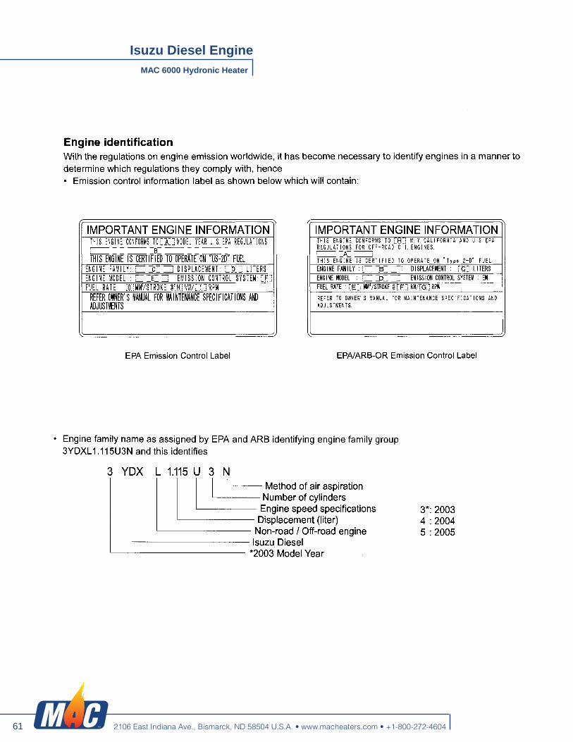
61
MAC 6000 Hydronic Heater
Isuzu Diesel Engine
2106 East Indiana Ave., Bismarck, ND 58504 U.S.A. • www.macheaters.com • +1-800-272-4604

62
MAC 6000 Hydronic Heater
Isuzu Diesel Engine
2106 East Indiana Ave., Bismarck, ND 58504 U.S.A. • www.macheaters.com • +1-800-272-4604

63
MAC 6000 Hydronic Heater
Isuzu Diesel Engine
2106 East Indiana Ave., Bismarck, ND 58504 U.S.A. • www.macheaters.com • +1-800-272-4604

64
MAC 6000 Hydronic Heater
Isuzu Diesel Engine
2106 East Indiana Ave., Bismarck, ND 58504 U.S.A. • www.macheaters.com • +1-800-272-4604

65
MAC 6000 Hydronic Heater
Isuzu Diesel Engine
2106 East Indiana Ave., Bismarck, ND 58504 U.S.A. • www.macheaters.com • +1-800-272-4604

66
MAC 6000 Hydronic Heater
Isuzu Diesel Engine
2106 East Indiana Ave., Bismarck, ND 58504 U.S.A. • www.macheaters.com • +1-800-272-4604

67
MAC 6000 Hydronic Heater
Isuzu Diesel Engine
2106 East Indiana Ave., Bismarck, ND 58504 U.S.A. • www.macheaters.com • +1-800-272-4604

68
MAC 6000 Hydronic Heater
Isuzu Diesel Engine
2106 East Indiana Ave., Bismarck, ND 58504 U.S.A. • www.macheaters.com • +1-800-272-4604

69
MAC 6000 Hydronic Heater
Isuzu Diesel Engine
2106 East Indiana Ave., Bismarck, ND 58504 U.S.A. • www.macheaters.com • +1-800-272-4604

70
MAC 6000 Hydronic Heater
Isuzu Diesel Engine
2106 East Indiana Ave., Bismarck, ND 58504 U.S.A. • www.macheaters.com • +1-800-272-4604

71
MAC 6000 Hydronic Heater
Isuzu Diesel Engine
2106 East Indiana Ave., Bismarck, ND 58504 U.S.A. • www.macheaters.com • +1-800-272-4604

72
MAC 6000 Hydronic Heater
Isuzu Diesel Engine
2106 East Indiana Ave., Bismarck, ND 58504 U.S.A. • www.macheaters.com • +1-800-272-4604

73
MAC 6000 Hydronic Heater
Isuzu Diesel Engine
2106 East Indiana Ave., Bismarck, ND 58504 U.S.A. • www.macheaters.com • +1-800-272-4604

74
MAC 6000 Hydronic Heater
Isuzu Diesel Engine
2106 East Indiana Ave., Bismarck, ND 58504 U.S.A. • www.macheaters.com • +1-800-272-4604

75
MAC 6000 Hydronic Heater
Isuzu Diesel Engine
2106 East Indiana Ave., Bismarck, ND 58504 U.S.A. • www.macheaters.com • +1-800-272-4604

76
MAC 6000 Hydronic Heater
Isuzu Diesel Engine
2106 East Indiana Ave., Bismarck, ND 58504 U.S.A. • www.macheaters.com • +1-800-272-4604

77
MAC 6000 Hydronic Heater
Isuzu Diesel Engine
2106 East Indiana Ave., Bismarck, ND 58504 U.S.A. • www.macheaters.com • +1-800-272-4604

78
MAC 6000 Hydronic Heater
Isuzu Diesel Engine
2106 East Indiana Ave., Bismarck, ND 58504 U.S.A. • www.macheaters.com • +1-800-272-4604

79
MAC 6000 Hydronic Heater
Isuzu Diesel Engine
2106 East Indiana Ave., Bismarck, ND 58504 U.S.A. • www.macheaters.com • +1-800-272-4604

80
MAC 6000 Hydronic Heater
Isuzu Diesel Engine
2106 East Indiana Ave., Bismarck, ND 58504 U.S.A. • www.macheaters.com • +1-800-272-4604

81
MAC 6000 Hydronic Heater
Isuzu Diesel Engine
2106 East Indiana Ave., Bismarck, ND 58504 U.S.A. • www.macheaters.com • +1-800-272-4604

82
MAC 6000 Hydronic Heater
Isuzu Diesel Engine
2106 East Indiana Ave., Bismarck, ND 58504 U.S.A. • www.macheaters.com • +1-800-272-4604

83
MAC 6000 Hydronic Heater
Isuzu Diesel Engine
2106 East Indiana Ave., Bismarck, ND 58504 U.S.A. • www.macheaters.com • +1-800-272-4604

84
MAC 6000 Hydronic Heater
Isuzu Diesel Engine
2106 East Indiana Ave., Bismarck, ND 58504 U.S.A. • www.macheaters.com • +1-800-272-4604

85
MAC 6000 Hydronic Heater
Isuzu Diesel Engine
2106 East Indiana Ave., Bismarck, ND 58504 U.S.A. • www.macheaters.com • +1-800-272-4604

86
MAC 6000 Hydronic Heater
Isuzu Diesel Engine
2106 East Indiana Ave., Bismarck, ND 58504 U.S.A. • www.macheaters.com • +1-800-272-4604

87
MAC 6000 Hydronic Heater
Isuzu Diesel Engine
2106 East Indiana Ave., Bismarck, ND 58504 U.S.A. • www.macheaters.com • +1-800-272-4604

88
MAC 6000 Hydronic Heater
Isuzu Diesel Engine
2106 East Indiana Ave., Bismarck, ND 58504 U.S.A. • www.macheaters.com • +1-800-272-4604

89
MAC 6000 Hydronic Heater
Isuzu Diesel Engine
2106 East Indiana Ave., Bismarck, ND 58504 U.S.A. • www.macheaters.com • +1-800-272-4604

90
MAC 6000 Hydronic Heater
Isuzu Diesel Engine
2106 East Indiana Ave., Bismarck, ND 58504 U.S.A. • www.macheaters.com • +1-800-272-4604

91
MAC 6000 Hydronic Heater
Isuzu Diesel Engine
2106 East Indiana Ave., Bismarck, ND 58504 U.S.A. • www.macheaters.com • +1-800-272-4604

92
MAC 6000 Hydronic Heater
Isuzu Diesel Engine
2106 East Indiana Ave., Bismarck, ND 58504 U.S.A. • www.macheaters.com • +1-800-272-4604

93
MAC 6000 Hydronic Heater
Isuzu Diesel Engine
2106 East Indiana Ave., Bismarck, ND 58504 U.S.A. • www.macheaters.com • +1-800-272-4604

94
MAC 6000 Hydronic Heater
Isuzu Diesel Engine
2106 East Indiana Ave., Bismarck, ND 58504 U.S.A. • www.macheaters.com • +1-800-272-4604

95
MAC 6000 Hydronic Heater
Isuzu Diesel Engine
2106 East Indiana Ave., Bismarck, ND 58504 U.S.A. • www.macheaters.com • +1-800-272-4604

96
MAC 6000 Hydronic Heater
Isuzu Diesel Engine
2106 East Indiana Ave., Bismarck, ND 58504 U.S.A. • www.macheaters.com • +1-800-272-4604

97
MAC 6000 Hydronic Heater
Isuzu Diesel Engine
2106 East Indiana Ave., Bismarck, ND 58504 U.S.A. • www.macheaters.com • +1-800-272-4604

98
MAC 6000 Hydronic Heater
Isuzu Diesel Engine
2106 East Indiana Ave., Bismarck, ND 58504 U.S.A. • www.macheaters.com • +1-800-272-4604

99
MAC 6000 Hydronic Heater
Isuzu Diesel Engine
2106 East Indiana Ave., Bismarck, ND 58504 U.S.A. • www.macheaters.com • +1-800-272-4604

100
MAC 6000 Hydronic Heater
Isuzu Diesel Engine
2106 East Indiana Ave., Bismarck, ND 58504 U.S.A. • www.macheaters.com • +1-800-272-4604

101
MAC 6000 Hydronic Heater
Isuzu Diesel Engine
2106 East Indiana Ave., Bismarck, ND 58504 U.S.A. • www.macheaters.com • +1-800-272-4604

102
MAC 6000 Hydronic Heater
Isuzu Diesel Engine
2106 East Indiana Ave., Bismarck, ND 58504 U.S.A. • www.macheaters.com • +1-800-272-4604

103
MAC 6000 Hydronic Heater
Isuzu Diesel Engine
2106 East Indiana Ave., Bismarck, ND 58504 U.S.A. • www.macheaters.com • +1-800-272-4604

104
MAC 6000 Hydronic Heater
Isuzu Diesel Engine
2106 East Indiana Ave., Bismarck, ND 58504 U.S.A. • www.macheaters.com • +1-800-272-4604

105
MAC 6000 Hydronic Heater
Isuzu Diesel Engine
2106 East Indiana Ave., Bismarck, ND 58504 U.S.A. • www.macheaters.com • +1-800-272-4604

106
MAC 6000 Hydronic Heater
Isuzu Diesel Engine
2106 East Indiana Ave., Bismarck, ND 58504 U.S.A. • www.macheaters.com • +1-800-272-4604

107
MAC 6000 Hydronic Heater
Isuzu Diesel Engine
2106 East Indiana Ave., Bismarck, ND 58504 U.S.A. • www.macheaters.com • +1-800-272-4604

108
MAC 6000 Hydronic Heater
Isuzu Diesel Engine
2106 East Indiana Ave., Bismarck, ND 58504 U.S.A. • www.macheaters.com • +1-800-272-4604

109
MAC 6000 Hydronic Heater
Isuzu Diesel Engine
2106 East Indiana Ave., Bismarck, ND 58504 U.S.A. • www.macheaters.com • +1-800-272-4604

110
MAC 6000 Hydronic Heater
Isuzu Diesel Engine
2106 East Indiana Ave., Bismarck, ND 58504 U.S.A. • www.macheaters.com • +1-800-272-4604

111
MAC 6000 Hydronic Heater
Isuzu Diesel Engine
2106 East Indiana Ave., Bismarck, ND 58504 U.S.A. • www.macheaters.com • +1-800-272-4604

112
MAC 6000 Hydronic Heater
Isuzu Diesel Engine
2106 East Indiana Ave., Bismarck, ND 58504 U.S.A. • www.macheaters.com • +1-800-272-4604

113
MAC 6000 Hydronic Heater
Isuzu Diesel Engine
2106 East Indiana Ave., Bismarck, ND 58504 U.S.A. • www.macheaters.com • +1-800-272-4604

114
MAC 6000 Hydronic Heater
Isuzu Diesel Engine
2106 East Indiana Ave., Bismarck, ND 58504 U.S.A. • www.macheaters.com • +1-800-272-4604

115
MAC 6000 Hydronic Heater
Isuzu Diesel Engine
2106 East Indiana Ave., Bismarck, ND 58504 U.S.A. • www.macheaters.com • +1-800-272-4604

116
MAC 6000 Hydronic Heater
Isuzu Diesel Engine
2106 East Indiana Ave., Bismarck, ND 58504 U.S.A. • www.macheaters.com • +1-800-272-4604

117
MAC 6000 Hydronic Heater
Isuzu Diesel Engine
2106 East Indiana Ave., Bismarck, ND 58504 U.S.A. • www.macheaters.com • +1-800-272-4604

118
MAC 6000 Hydronic Heater
Isuzu Diesel Engine
2106 East Indiana Ave., Bismarck, ND 58504 U.S.A. • www.macheaters.com • +1-800-272-4604

119
MAC 6000 Hydronic Heater
Isuzu Diesel Engine
2106 East Indiana Ave., Bismarck, ND 58504 U.S.A. • www.macheaters.com • +1-800-272-4604

120
MAC 6000 Hydronic Heater
Isuzu Diesel Engine
2106 East Indiana Ave., Bismarck, ND 58504 U.S.A. • www.macheaters.com • +1-800-272-4604

121
MAC 6000 Hydronic Heater
Isuzu Diesel Engine
2106 East Indiana Ave., Bismarck, ND 58504 U.S.A. • www.macheaters.com • +1-800-272-4604

122
MAC 6000 Hydronic Heater
Isuzu Diesel Engine
2106 East Indiana Ave., Bismarck, ND 58504 U.S.A. • www.macheaters.com • +1-800-272-4604
IDE -6144
IDE -6144

123
MAC 6000 Hydronic Heater
Generator
2106 East Indiana Ave., Bismarck, ND 58504 U.S.A. • www.macheaters.com • +1-800-272-4604
I ALTERNATORI AUTOREGOLATI SERIE ECP3
ISTRUZIONI PER L‟USO E LA MANUTENZIONE GB
SELF- REGULATING ALTERNATORS SERIES ECP3 OPERATING AND MAINTENANCE INSTRUCTIONS
F ALTERNATEURS AUTO - REGULES SERIE ECP3
MANUEL D‟INSTRUCTION ET DE MAINTENANCE D
SELBSTREGELNDER GENERATOR SERIE ECP3 BETRIEBS-UND WARTUNGSANLEITUNG
ES ALTERNADORES AUTOREGULADOS SERIE ECP3
INSTRUCCIONES PARA USO Y MANTENIMIENTO
ECP3

124
MAC 6000 Hydronic Heater
Generator
2106 East Indiana Ave., Bismarck, ND 58504 U.S.A. • www.macheaters.com • +1-800-272-4604
ECP3 Manual - March 2013 rev. 03 2
DESCRIZIONE MACCHINA
INDICE
I generatori della serie ECP3 sono auto-regolati, brushless a 2 e 4 poli. Hanno induttore rotante provvisto di gabbia di smorzamento (generatori a 2 poli) e indotto fisso a cave inclinate. Gli avvolgimenti sono a passo raccor-ciato per ridurre il contenuto armonico. I generatori sono costruiti in conformità alle direttive 2006/42, 2006/95, 2004/108 e relative modifiche, alle nor-me CEI 2-3, EN 60034-1, IEC 34-1, VDE 0530, BS4999 - 5000. Le prove per la verifica della compatibili-ta‟ elettromagnetica sono state eseguite nelle condizioni prescritte dalle norme, con il neutro collegato a terra. Esecuzio-ni in accordo ad altre specifiche posso-no essere eseguite su richiesta del cliente. La struttura meccanica, sempre molto robusta, consente un facile accesso ai collegamenti e permette di eseguire le verifiche nelle diverse parti altrettanto facilmente. La carcassa e‟ realizzata in acciaio, gli scudi in alluminio pressofuso, l‟albero in acciaio C45 con ventola calettata. Il grado di protezione e‟ IP23 (a richie-sta e‟ possibile realizzare un grado di protezione superiore). Gli isolamenti sono eseguiti in classe H, le impregnazioni con resine epossidiche per le parti rotanti e trattamenti sotto-vuoto per le parti di piu‟ elevata tensio-ne, quali gli statori (a richiesta tratta-menti speciali). Nel campo dei radio di-sturbi, la produzione di serie soddisfa la norma EN61000-6-3, EN61000-6-1.
DESCRIZIONE MACCHINA
PREMESSA
IDENTIFICAZIONE MACCHINA
VERIFICA ALLA CONSEGNA
PRESCRIZIONI DI SICUREZZA
TRASPORTO E IMMAGAZZINAMENTO
ACCOPPIAMENTO MECCANICO
ACCOPPIAMENTO ELETTRICO
AVVIAMENTO E ARRESTO
PULIZIA E LUBRIFICAZIONE
MANUTENZIONE
ANOMALIE E RIMEDI
PARTI DI RICAMBIO
TAVOLE
DIMENSIONI D’INGOMBRO
2-3
4-5
4-5
4-5
4-13
14-17
16-21
22-25
26-27
26-27
26-33
34-35
36-37
38-42
43
PAG INDEX
MACHINE DESCRIPTION
INTRODUCTION
MACHINE IDENTIFICATION
INSPECTION ON DELIVERY
SAFETY REQUIREMENTS
TRANSPORT AND STORAGE
MECHANICAL COUPLING
ELECTRICAL CONNECTIONS
STARTING AND STOPPING OPERATIONS
CLEANING AND LUBRICATION
MAINTENANCE
DEFECTS AND REMEDIES
SPARE PARTS
TABLES
OVERALL DIMENSIONS
MACHINE DESCRIPTION ECP3 2 and 4 pole alternators are brushless, self regulating and incorpora-te a rotating inductor with damper cage (2 pole generators) and a fixed stator with skewed slots. The stator windings have a shortened pitch to reduce the harmonic content of the output wave-form. The alternators are made in com-pliance with the 2006/42, 2006/95, 2004/108 d i rect i ves and the i r amendments, and the CEI 2-3, EN60034-1, IEC34-1, VDE0530, BS 4999-5000 regulations. Tests to verify the electromagnetic com-pability have been carried out in the fo-reseen conditions by the standards with the neutral connected to the earth. On customer‟s request alternators can be manufactured according to different specifications. The robust mechanical construction gi-ves good access to the generator output connections, and allows the user to in-spect the various components with ea-se. The casing is made of steel, the shields of cast iron, and the shaft of C45 steel and it has a keyed fan. The mechanical protection level meets standard IP23 (upon request higher le-vels of protection can be supplied). Insulation materials meet class H requi-rements, and all rotating components are epossy resins impregnated, higher voltage parts, such as the stators, are vacuum-treated (special treatments are available on request). Radio interferen-ce suppression meets the requirements of EN61000-6-3, EN61000-6-1 regula-tions.

125
MAC 6000 Hydronic Heater
Generator
2106 East Indiana Ave., Bismarck, ND 58504 U.S.A. • www.macheaters.com • +1-800-272-4604
ECP3 Manual - March 2013 rev. 03 4
PREMESSA
I generatori della serie ECP3, rispondono alle direttive CEE 2006/42, 2009/95, 2004/108 e loro modifiche; pertanto non presentano pericolo per l‟operatore, se installati, usati, manutenuti secondo le istruzioni fornite dalla Mecc Alte e a condizione che i dispositivi di sicurezza siano tenuti in perfetta efficienza. Per questa ragione occorre attenersi scrupolosamente alle istruzioni indicate in questo manuale. E‟ vietata qualsiasi riproduzione di questo manuale.
Per qualsiasi comunicazione con la Mecc Alte o con i centri di assistenza autorizzati, citare sempre il tipo e il codice del generatore.
VERIFICA ALLA CONSEGNA
IDENTIFICAZIONE MACCHINA
Prima di qualsiasi intervento di pulizia, lubrificazione o manutenzione il motore primario a cui e‟ collegato il generatore non deve essere in funzione, ma fermo e isolato dalle sue fonti di energia. Per fermare il generatore occorre seguire scrupolosamente la procedura di arresto del sistema di trascinamento; il generatore non e‟ previsto di Stop/Emergenza, ma si arresta istantaneamente in relazione al sistema di arresto predisposto dall‟installatore.
PRESCRIZIONI DI SICUREZZA
Alla consegna del generatore controllare con la bolla di accompagnamento che non ci siano danni o parti mancanti; nel caso informare immediatamente lo spedizionere, l‟assicurazione, il rivenditore o la Mecc Alte.
INTRODUCTION
The ECP3 alternators comply with the EEC directives 2006/42, 2009/95, 2004/108 and their amendments; therefore they pose no danger to the operator if they are installed, used and maintained according to the instruc-tions given by Mecc Alte and provided the safety devices are kept in perfect working conditions. Therefore a strict observance of these instruc-tions is required. Any reproduction of this manual is forbidden.
MACHINE IDENTIFICATION
Always indicate the generator type and code when contacting Mecc Alte or the authorized after-sales service centres.
INSPECTION ON DELIVERY
When the alternator is delivered, check that unit conforms with the delivery note and en-sure that there are no damaged or defective parts; should there be any, please inform the forwarding agent, the insurance company, the seller or Mecc Alte immediately.
SAFETY REQUIREMENTS
Before any cleaning, lubrication or maintenance operation, ensure that the generator is stationary and disconnected from the power supply. When stopping the generator, ensure the compliance with the procedures for stopping the prime mover. The generator, in fact, has no Emergency Stop, but is controlled by the device arranged by the installer.

126
MAC 6000 Hydronic Heater
Generator
2106 East Indiana Ave., Bismarck, ND 58504 U.S.A. • www.macheaters.com • +1-800-272-4604
ECP3 Manual - March 2013 rev. 03 6
IMPORTANT This symbol warns the personnel concer-ned that the described operation may cau-se damages to the machine if it is not car-ried out according to the safety standards. CAUTION This symbol warns the personnel concer-ned that the described operation may cau-se damages to the machine and/or injures to the personnel if it is not carried out ac-cording to the safety standards. WARNING This symbol warns the personnel concer-ned that the described operation may cau-se serious injuries or death to the person-nel if it is not carried out according to the safety standards. DANGER This symbol warns the personnel concer-ned that the described operation may im-mediately cause serious injuries or death to the personnel if it is not carried out ac-cording to the safety standards.
SAFETY REQUIREMENTS
Symbols having specific meanings have been used throughout this instruction and maintenance manual.
CONVENTIONAL SYMBOLS AND SYMBOL DESCRIPTION
Durante la consultazione del presente ma-nuale d‟uso e manutenzione troverete alcuni simboli; questi hanno un preciso significato.
PRESCRIZIONI DI SICUREZZA
SIMBOLOGIA CONVENZIONALE E SUA DEFINIZIONE
IMPORTANTE Segnala al personale interessato che l’ope-razione descritta presenta un rischio che può avere come conseguenza un danno alla macchina, se non effettuata nel rispet-to delle normative di sicurezza. ACCORTEZZA Segnala al personale interessato che l’ope-razione descritta presenta un rischio che può avere come conseguenza un danno alla macchina e/o lesioni al personale stes-so, se non effettuata nel rispetto delle nor-mative di sicurezza. AVVERTIMENTO Segnala al personale interessato che l’ope-razione descritta presenta un rischio che può avere come conseguenza lesioni gravi o morte, se non effettuata nel rispetto delle normative di sicurezza. PERICOLO Segnala al personale interessato che l’ope-razione descritta presenta un rischio im-mediato che ha come conseguenza lesioni gravi o morte, se non effettuata nel rispetto delle normative di sicurezza.
IMPORTANTE IMPORTANT
WICHTIG

127
MAC 6000 Hydronic Heater
Generator
2106 East Indiana Ave., Bismarck, ND 58504 U.S.A. • www.macheaters.com • +1-800-272-4604
ECP3 Manual - March 2013 rev. 03 8
SAFETY REQUIREMENTS
PRESCRIZIONI DI SICUREZZA
HANDLER This symbol identifies the type of operator in charge of the operation described. This qualification requires a complete know-ledge and understanding of the information contained in the manufacturer‟s instruction manual as well as specific skills about the hoi-sting means, slinging methods and features and safe handling procedures. MECHANICAL SERVICE MAN This symbol identifies the type of operator in charge of the operation described. This qualification requires a complete know-ledge and understanding of the information contained in the manufacturer‟s instruction manual as well as specific skills necessary to perform installation, adjustment, maintenance, cleaning and/or repair operations. ELECTRICAL SERVICE MAN This symbol identifies the type of operator in charge of the operation described. This qualification requires a complete know-ledge and understanding of the information contained in the manufacturer‟s instruction manual as well as specific skills necessary to perform electrical operations such as connec-tions, adjustment, maintenance and/or repair. The electrical service man must be able to work even in case electrical cabinets and panels are live. In case of exceptional operations and upon written request of servicing operations please apply to Mecc Alte authorized centers.
ADDETTO ALLA MOVIMENTAZIONE Identifica il tipo di operatore a cui è riservato l‟intervento trattato. Questa qualifica presuppone una piena cono-scenza e comprensione delle informazioni contenute nel manuale d‟uso del costruttore oltre che competenze specifiche dei mezzi di sollevamento, dei metodi e delle caratteristi-che d‟imbragatura e della movimentazione in sicurezza. MANUTENTORE MECCANICO Identifica il tipo di operatore a cui è riservato l‟intervento trattato. Questa qualifica presuppone una piena cono-scenza e comprensione delle informazioni contenute nel manuale d‟uso del costruttore oltre che competenza specifica per effettuare gli interventi di installazione, regolazione, ma-nutenzione, pulizia e/o riparazione. MANUTENTORE ELETTRICO Identifica il tipo di operatore a cui è riservato l‟intervento trattato. Questa qualifica presuppone una piena cono-scenza e comprensione delle informazioni contenute nel manuale d‟uso del costruttore oltre che competenza specifica per gli inter-venti di natura elettrica di collegamento, rego-lazione, manutenzione e/o riparazione. E’ in grado di operare in presenza di tensione all’interno di armadi e qua-dri elettrici. Nel caso di interventi straordinari e su autoriz-zazione scritta del servizio assistenza rivolger-si ai centri autorizzati Mecc Alte.

128
MAC 6000 Hydronic Heater
Generator
2106 East Indiana Ave., Bismarck, ND 58504 U.S.A. • www.macheaters.com • +1-800-272-4604
ECP3 Manual - March 2013 rev. 03 10
Al momento dell‟installazione le norme preve-dono che il generatore sia collegato a terra. Per questa ragione assicurarsi che l‟impianto di messa a terra sia efficiente ed in conformi-ta‟ con le direttive del paese dove il generato-re sara‟ installato. ATTENZIONE L’INSTALLATORE FINALE E’ RE-SPONSABILE DELLA PREDISPOSI-ZIONE DI TUTTE LE PROTEZIONI (DISPOSITIVI DI SEZIONAMENTO, PROTEZIONI CONTRO I CONTATTI DIRETTI E INDIRETTI, PROTEZIONI CONTRO SOVRACORRENTI E SO-VRATENSIONI, ARRESTO DI EMER-GENZA ECC.) NECESSARIE PER RENDERE CONFORME IL MACCHI-NARIO E L’IMPIANTO UTILIZZATO-RE, ALLE VIGENTI NORME DI SICU-REZZA INTERNAZIONALI/ EUROPEE. Per la movimentazione dei generatori disim-ballati usare sempre ed esclusivamente gli appositi golfari. Utilizzare funi di portata adeguata senza sol-levare il generatore troppo dal pavimento (max 30 cm.) Alla fine del periodo di vita della macchina, rivolgersi alle agenzie di smaltimento materiali ferrosi e non disperderne parti nell‟ambiente. Gli addetti all‟installazione, conduzione e ma-nutenzione del generatore devono essere tecnici adeguatamente qualificati e che cono-scano le caratteristiche dei generatori. Le persone addette alla movimentazione de-vono sempre indossare guanti da lavoro e scarpe antinfortunistiche. Qualora il generatore o l‟intero impianto deb-ba essere sollevato da terra, gli operatori de-vono usare un casco protettivo. Il generatore va installato in un ambiente ae-rato. Se non c‟e‟ sufficiente aria oltre al mal funzionamento esiste pericolo di surriscalda-mento. Sulla porta di ingresso del locale ci deve essere un cartello indicante il divieto di accesso alle persone non autorizzate. Assicurarsi che il basamento del generatore e del motore primario sia calcolato per sop-portarne il peso e tutti gli eventuali sforzi do-vuti al funzionamento. E‟ responsabilità dell‟installatore il corretto accoppiamento del generatore al motore, mettendo in atto tutti quegli accorgimenti ne-cessari per garantire il corretto funzionamen-to del generatore ed evitare anomale solleci-tazioni che possono danneggiare il generato-re (come vibrazioni, disallineamenti, strane sollecitazioni etc). La macchina è stata progettata per garantire la potenza nominale in ambienti con tempe-ratura massima di 40 °C e altitudine inferiore ai 1000 metri (EN60034-1), se non diversa-mente indicato. Per condizioni diverse vede-re il catalogo commerciale (depliant).
PRESCRIZIONI DI SICUREZZA
SAFETY REQUIREMENTS
Before installing the generator, arrange-ments must be made to earth the machine in compliance with any relevant electrical regu-lations.This is the reason why you must ma-ke sure that the grounding system is in good conditions and in compliance with the regula-tions of the country where the generator will be installed. CAUTION THE FINAL INSTALLER IS RESPONSI-BLE FOR THE INSTALLATION OF ALL THE PROTECTIONS (SECTIONING DEVI-CES, PROTECTIONS AGAINST DIRECT AND INDIRECT CONTACTS, OVERCUR-RENT AND OVERVOLTAGE PROTEC-TIONS, EMERGENCY STOP, ETC.) NE-CESSARY FOR THE MACHINE TO COM-PLY WITH THE EXISTING INTERNATIO-NAL/EUROPEAN SAFETY REGULA-TIONS. For handling the unpacked generators, al-ways use the special eyebolts only; use ro-pes having a suitable carriyng capacity and do not lift the generator too much from the floor (max 30 cm.). When the machine is worn cut, contact the companies in charge of the disposal of fer-rous material and do not throw away its parts into the environment. The operators in charge of the installation, operation and maintenance of the genera-tors must be skilled technicians who know the characteristics of the generators. The people in charge of the handling must always wear work gloves and safety shoes. In case the generator or the whole plant must be lifted from the floor, the operators must wear a safety helmet. The generator must be installed in an airy room. If there is not enough air, a malfunction or an overheating may occur. All entry doors into generator room should be clearly mar-ked “Authorized persons only”. Take sure that gen-set foundations and ba-seframe are suitable to bear the combined weight of the alternators and prime mover. The installer is responsible for the correct coupling of the generator to the engine and for the performance of all precautions neces-sary to guarantee the correct operation of the generator and avoid abnormal stress, which could damage the generator (such as vibra-tions, misalignment, strange noises or vibra-tions, etc.) The machine was designed to guarantee the nominal power in environments with a maxi-mum temperature of 40° C, at altitudes lower than 1000 m asl (EN60034-1), unless other-wise specified; for different operating condi-tions, see the commercial catalogue (brochure).

129
MAC 6000 Hydronic Heater
Generator
2106 East Indiana Ave., Bismarck, ND 58504 U.S.A. • www.macheaters.com • +1-800-272-4604
ECP3 Manual - March 2013 rev. 03 12
Nelle vicinanze della macchina non ci devono essere persone con indumenti svolazzanti tipo: sciarpe, fular, bracciali, etc e qualsiasi indumento deve essere chiuso con elastici alle estremita‟. I generatori non devono mai e per nessuna ragione funzionare con le seguenti protezioni aperte: - copertura frontale. - protezioni delle ventole. A richiesta puo‟ essere montato un tipo di regolatore corredato di segnalazioni a led, che sono: Verde - funzionamento regolare Giallo - intervento protezione sovraccarico Rosso - intervento protezione bassa
velocita‟ I generatori sono rumorosi; anche se il livello acustico è sicuramente inferiore a quello del motore primario, devono essere installati in ambienti isolati (stanza, sala macchine, etc.) e chi vi accede deve munirsi di cuffie antirumore. I generatori sviluppano calore anche elevato in funzione della potenza generata. Pertanto non toccare il generatore se non con guanti antiscottatura e attendere, una volta spento, che esso raggiunga la temperatura ambiente. Anche se la macchina e‟ protetta in tutte le sue parti evitare di sostare nelle sue vicinanze. Per nessuna ragione appoggiarsi o sedersi sul generatore. Non togliere per nessuna ragione le etichette, anzi richiederne la sostituzione in caso di necessita‟. PERICOLO DI CORTO CIRCUITO Il generatore e‟ costruito con grado di protezione IP23; pertanto e‟ fatto divieto di spruzzare o di mettere contenitori di liquidi sopra le parti elettriche. In caso di sostituzione di pezzi di ricambio richiedere esclusivamente ricambi originali. Per la sostituzione di parti usurate comportarsi rigorosamente come descritto al capitolo manutenzione; queste manutenzioni devono essere eseguite da tecnici adeguatamente qualificati.
PRESCRIZIONI DI SICUREZZA
SAFETY REQUIREMENTS
No person must wear fluttering clothes (such as scarves, etc.) near the machine and any garment must be fastened with elastic bands at its ends. The generators must never and for no reason run whith following guards removed: - terminals cover - fan guards. If required, the generator can be equipped with a regulator with led display, as follows: Green - regular operation Yellow - overload protection activated Red - low speed protection activated The generators are noisy; even if the sound level is certainly lower than that of the prime motor, they must be installed in soundproof rooms (room, engine room, etc.) where it is necessary to wear antinoise car protectors. The generators produce heat proportional to the output. Therefore, do not touch the generator if you do not wear antiscorch gloves and, after switching it off, do not touch it until it has cooled down. Even if all the machine components are protected, keep away from the machine. Do not lean or sit on the generator for whatever reason. Do not remove the labels for whatever reason; on the contrary, if necessary, replace them. DANGER OF SHORT CIRCUIT The degree of protection of the generator is IP23; short circuits may occur if liquids are spilt onto areas containing electrical parts. In case of replacement of spare parts, use original spare parts only. For the replacement of worn parts, carefully follow the maintenance instruction; these operations must be carried out by skilled technicians.

130
MAC 6000 Hydronic Heater
Generator
2106 East Indiana Ave., Bismarck, ND 58504 U.S.A. • www.macheaters.com • +1-800-272-4604
ECP3 Manual - March 2013 rev. 03 14
In funzione della destinazione gli alternatori possono essere imballati per la spedizione in vari modi. In ogni caso per movimentarli, osservare nel-la bolla di accompagnamento, il peso, e con mezzi adeguati, sollevare da terra il meno possibile. Nel caso che l‟imballo debba essere movi-mentato con carrelli, occorre che le forche siano tenute il piu‟ larghe possibile in modo da evitare cadute o scivolamenti. In caso di immagazzinamento, gli alternatori imballati e non, devono essere depositati in un locale fresco e asciutto o comunque mai esposto alle intemperie. Una volta disimballato il generatore, (monosupporto) non scollegare il sistema di fissaggio rotore, in quanto quest‟ultimo po-trebbe scivolare. Per la movimentazione al fine dell‟installazio-ne, sollevare i generatori, sempre, attraverso i propri golfari.
TRASPORTO E IMMAGAZZINAMENTO
ATTENZIONE: DOPO LUNGHI PERIODI DI IMMA-GAZZINAMENTO O IN PRESENZA DI SEGNI EVIDENTI DI UMIDITA’/ CONDENSA, VERIFICARE LO STA-TO DI ISOLAMENTO. LA PROVA DI ISOLAMENTO DEVE ESSERE ESEGUITA DA UN TECNI-CO ADEGUATAMENTE QUALIFICA-TO. PRIMA DI ESEGUIRE TALE PROVA E’ NECESSARIO SCONNETTERE IL REGOLATORE DI TENSIONE; SE LE PROVE DARANNO UN RISULTATO TROPPO BASSO (INFERIORE A 1 MΩ)(EN60204-1) SI DOVRA ASCIU-GARE L’ALTERNATORE IN UN FOR-NO A 50-60°C.
TRANSPORT AND STORAGE
PLEASE NOTE : AFTER PROLONGER STORAGE OR IF THE MACHINES SHOW SIGNS OF CONDENSATION, ALL WINDINGS SHOULD BE SUBJECTED TO INSU-LATION TESTS PRIOR TO OPERA-TING. THE INSULATION TEST SHALL BE MADE BY SKILLED PERSONNEL. BEFORE CARRYING OUT THE TEST, THE VOLTAGE REGULATOR MUST BE DISCONNECTED; IF THE TEST RESULTS ARE TOO LOW (LOWER THAN 1 MΩ)(EN60204-1) THE ALTERNATOR MUST BE DRIED IN AN OVEN AT 50-60°C.
Alternators will be packed for shipment in a manner suitable to their mode of transport and final destination. Prior to handling goods, please ensure that lifting equipment is of sufficient capacity. Un-der lifting conditions machinery should be ele-vated to a minimal distance from the ground. When lifting or moving goods by forklift appa-ratus, care should be taken to ensure that forks are correctly positioned to prevent slip-ping or falling of pallet or crate. Both packed and unpacked alternators shall be stored in a cool and dry room, and shall never be exposed to the inclemency of the weather. With regard to single bearing alternators (form MD35) please ensure that the rotor securing device is in place. Failure to do so may lead to slippage or assembly. When installing the alternators, always lift them by using their eyebolts.

131
MAC 6000 Hydronic Heater
Generator
2106 East Indiana Ave., Bismarck, ND 58504 U.S.A. • www.macheaters.com • +1-800-272-4604
ECP3 Manual - March 2013 rev. 03 16
Ricordarsi che, una volta che il generatore sara‟ accoppiato al motore primario, o montato su un basamento, o installato in un telaio in modo da formare un corpo unico, non dovra piu‟ essere sollevato dai propri golfari ma si dovranno seguire le indicazioni dell‟installatore. Non disperdere l‟imballo nell‟ambiente, ma rivolgersi alle agenzie di smaltimento.
TRASPORTO E IMMAGAZZINAMENTO
ACCOPPIAMENTO MECCANICO
L‟accoppiamento del generatore al motore primo e‟ a cura dell‟utilizzatore finale ed e‟ eseguito secondo la sua sola discrezione. Le attenzioni richieste sono: NELLA MESSA IN SERVIZIO AVER CURA CHE LE APERTURE DI ASPIRAZIONE E SCARICO DELL‟ARIA DI RAFFREDDA-MENTO SIANO SEMPRE LIBERE. IL LATO DI ASPIRAZIONE NON DEVE ES-SERE VICINO A SORGENTI DI CALORE. IN OGNI CASO, SE NON SPECIFICATA-MENTE CONCORDATO, LA TEMPERA-TURA DELL‟ARIA DI RAFFREDDAMENTO DEVE ESSERE QUELLA AMBIENTE E COMUNQUE NON SUPERIORE A 40°C.
IN CASO DI GENERATORI MONO-SUPPORTO IN FASE DI ACCOPPIA-MENTO CON IL MOTORE PRIMO, FARE ATTENZIONE CHE IL ROTO-RE NON SI SFILI; TOGLIERE IL SI-STEMA DI FISSAGGIO ROTORE.
TRANSPORT AND STORAGE
Once the generator is coupled with an engi-ne, mounted on a baseframe, or installed on a complete generating set, it cannot be lifted by its lifting bolts.The relevant instructions for lifting complete generating set should be fol-lowed. Any packing materials should be disposed of via correct waste disposal methods. Do not discard waste materials into the environment.
MECHANICAL COUPLING
The mechanical coupling is under the sole responsibility of the final user, and has to be done at his discretion. Warnings: BEFORE STARTING THE ALTERNATOR, CHECK THAT THE AIR INLETS AND OUT-LETS ARE FREE OF ANY OBSTRUC-TIONS. THE AIR INLETS SHOULD NOT BE NEAR ANY HEATING SOURCES. IN ANY CASE, IF NOT SPECIFICALLY RE-QUESTED, THE COOLING AIR TEMPE-RATURE MUST BE EQUAL TO THE ENVI-RONMENT TEMPERATURE AND NEVER HIGHER THAN 40°C.
BEFORE MECHANICAL COUPLING OF SINGLE BEARING ALTERNA-TORS REMOVE THE ROTOR SECU-RING DEVICE PLACED THERE TO PREVENT ROTOR FROM SLIPPING.
IMPORTANTE IMPORTANT
WICHTIG

132
MAC 6000 Hydronic Heater
Generator
2106 East Indiana Ave., Bismarck, ND 58504 U.S.A. • www.macheaters.com • +1-800-272-4604
ECP3 Manual - March 2013 rev. 03 18
Nel caso di accoppiamento di un gene-ratore serie ECP3 avente forma co-struttiva B3/B9 seguire le seguenti istruzioni: -) montare il coperchio anteriore sul motore fissandolo con le apposite viti e applicando una coppia di serraggio di 48±7% Nm se si impiegano viti M10 o 21±7% Nm nel caso di viti M8 (figura 1) -) bloccare l‟alternatore sul coperchio fissando i quattro dadi M8 sui tiranti, applicando una coppia di serraggio pari a 16 ±7% Nm (figura 2) -) inserire il tirante centrale nella sua sede ed avvitare il dado (figura 3) -) bloccare il tirante centrale applicando una coppia di serraggio pari a 21±7% Nm se si impiegano tiranti M8, mentre, se si impiegano tiranti M14, applicare una coppia di serraggio pari a 120±7% Nm; rimontare le retine di protezione laterali e la griglia di chiusura posteriore applicando sulle viti M5 una coppia di serraggio pari a 3,5±7% Nm (figura 4). -) Eliminare possibili carichi assiali nel cuscinetto battendo leggermente con un martello in gomma sulla sede del cuscinetto stesso.
ACCOPPIAMENTO MECCANICO
MECHANICAL COUPLING
When coupling with an ECP3 series generator having a B3/B9 form, follow the instructions below: -) mount the front cover on the motor, fixing it with the appropriate screws and applying a tightening torque of 48±7% Nm if using M10 screws or 21±7% Nm for M8 screws (figure 1) -) lock the alternator into the cover by fixing the four M8 nuts onto the bolts, applying a tightening torque of 16±7% Nm (figure 2) -) insert the central bolt into its housing and screw the nut (figure 3) -) block the central stay rod, applying a tightening torque of 21±7% Nm if you are using stay rods of M8, while if you are using M14 stay rods, apply a tightening torque of 120±7% Nm; reassemble the lateral protective nets and the rear closing grid by applying a tightening torque of 3,5±7% Nm to the M5 screws (figure 4) -) Eliminate possible axial loads in the bearing by tapping with a rubber hammer on the seat of the bearing.
Fig.1
Fig.2
Fig.3
Fig.4

133
MAC 6000 Hydronic Heater
Generator
2106 East Indiana Ave., Bismarck, ND 58504 U.S.A. • www.macheaters.com • +1-800-272-4604
ECP3 Manual - March 2013 rev. 03 20
Un allineamento impreciso può causare vibrazioni e danneggiamenti dei cusci-netti. E‟ consigliabile inoltre verificare la compatibilità delle caratteristiche torsio-nali del generatore e del motore (a cura del cliente). I dati sul generatore neces-sari per tale verifica sono disponibili nella relativa documentazione. Nel caso di accoppiamento di un gene-ratore serie ECP3 avente forma co-struttiva MD35 seguire le seguenti istru-zioni: -) verificare il corretto posizionamento dei dischi (quota “L”) in funzione del tipo di accoppiamento considerato (tavola 2 pag. 38); se necessario ripri-stinare la quota “L” spostando legger-mente e assialmente il rotore. In posi-zione corretta il cuscinetto posteriore deve avere un gioco assiale da 0,5 a 2 mm. -) avvicinare l‟alternatore al motore di accoppiamento -) allineare uno dei fori di fissaggio dei dischi del volano con il foro dei dischi precedentemente posizionato -) inserire ed avvitare parzialmente la relativa vite che blocca i dischi al vola-no. Ruotare il volano affinchè altri due fori si ripresentino nella stessa posizio-ne ed avvitare parzialmente la relativa vite. Ripetere detta operazione per tutti gli altri fori -) dopo aver verificato il corretto cen-traggio dei dischi nel volano motore, bloccare definitivamente dette viti -) montare le due retine laterali di prote-zione, fornite a corredo del generatore. -) Eliminare possibili carichi assiali nel cuscinetto battendo leggermente con un martello in gomma sulla sede del cuscinetto stesso. Solamente dopo che il generatore e‟ stato ben fissato meccanicamente pro-cedere all‟accoppiamento elettrico.
ACCOPPIAMENTO MECCANICO
MECHANICAL COUPLING
A bad alignment may cause vibrations and bearing damages. It is advisable to verify the compatibility of the generator torsional characteristics and the engine (by the customer). The necessary data for this verification are available on the concerning documentation. When coupling with an ECP3 series generator having a MD35 form, follow the instructions below: -) according to the type of the coupling, verify the correct placement of the discs (dimension “L”) (table 2 pag. 38); if ne-cessary restore the “L” dimension mo-ving gently and axially the rotor. In the right position the clearance of rear bea-ring should be from 0.5 to 2 mm. -) move the generator close to the cou-pling engine -) align one of the flywheel disk faste-ning holes with the holes of the pre-viously positioned disks -) Insert and partially tighten the screws that lock the disks to the flywheel. Turn the flywheel until another two holes are in the same position and partially tighten the screw. Repeat this operation for all the other holes -) after inspecting the correct centring of the disks on the engine flywheel, the screws must be completely tightened -) fix the two lateral protection grids supplied with the generator. -) Eliminate possible axial loads in the bearing by tapping with a rubber ham-mer on the seat of the bearing. Only after a correct mechanical cou-pling, proceed with the electrical con-nections.

134
MAC 6000 Hydronic Heater
Generator
2106 East Indiana Ave., Bismarck, ND 58504 U.S.A. • www.macheaters.com • +1-800-272-4604
ECP3 Manual - March 2013 rev. 03 22
ACCOPPIAMENTO ELETTRICO
L‟accoppiamento elettrico e‟ a cura dell‟utiliz-zatore finale ed e‟ eseguito secondo la sua sola discrezione. Per l‟ingresso nella scatola morsetti si racco-manda di utilizzare passacavi e serracavi in accordo con le specifiche del paese di espor-tazione. Collegamento avvolgimenti (tav. 3 pag. 39) Sono previsti entrambi i collegamenti, stella con neutro (Y) e triangolo (Δ) in tutti gli alter-natori. Per passare da un collegamento Y a Δ (es.da 400V a 230V) e’ sufficiente spostare i ponti sulla morsettiera principale (vedere schema tav. 3 pag. 39). Nessun intervento e‟ richiesto, sul regolatore di tensione. I generatori sono costruiti di serie con 12 cavi di uscita per consentire di ottenere tensioni diverse (es. 115 / 200 / 230 / 400V ). I generatori, vanno sempre collegati a terra con un conduttore di adeguata sezione utiliz-zando uno dei due (interno/esterno) appositi morsetti. Dopo aver eseguito il collegamento, rimonta-re il coperchio scatola morsetti. NOTA: variazioni di frequenza. La macchina fornita per funzionare a 50Hz puo‟ funzionare anche a 60Hz (o viceversa); e‟ sufficiente tarare il potenziometro al nuovo valore nominale di tensione. Passando da 50Hz a 60Hz, la potenza puo‟ aumentare del 20% (corrente invariata), se la tensione aumenta del 20%; se la tensione rimane invariata la potenza, puo‟ aumentare del 5% per effetto della migliore ventilazione. Per generatori costruiti appositamente per una frequenza di 60Hz nel passaggio a 50Hz, la tensione e la potenza devono ne-cessariamente diminuire del 20% rispetto a quelle riferite a 60Hz. REGOLATORE DI TENSIONE (tav. 4 pag. 39) L‟autoregolazione ottenuta tramite il regolato-re elettronico tipo DSR garantisce in condizio-ni statiche una precisione della tensione del ± 1% con qualsiasi fattore di potenza e con va-riazione di velocita‟ compresa fra -10% e + 20%. ATTENZIONE : Il controllo di tensione va eseguito a vuoto con l‟alternatore funzionante a frequenza no-minale. Agendo sul potenziometro tensione dei rego-latori elettronici si puo‟ ottenere la regolazione della tensione entro il ±14% del valore nomi-nale. E‟ anche possibile, inserendo un potenziome-tro da 10KΩ negli appositi morsetti (10-11), ottenere la regolazione della tensione entro il ± 14% del valore nominale. Per maggiori dettagli sui regolatori consultare il manuale specifico.
ELECTRICAL CONNECTIONS
All electrical output connections are the re-sponsibility of, and are at the discretion of, the end user. When making terminal box connections, all cable and terminal lugs should meet the rele-vant standards of the country of final destina-tion. Windings connection (table. 3 pag. 39) All alternators feature both star with neutral(Y) and delta (Δ) connections. To reconnect from a star to delta connection (for ex. from 400V to 230V), modify the linking arrangements on the output terminal board (see diagram on table 3 page 39). It is not necessary to adjust the voltage regu-lator. Standard alternators are equipped with 12 cables to offer different voltages (for example 115 / 200 / 230 / 400). The alterrnator must always be earthed by sufficiently rated cable, using one of the inside or outside terminals. After completing output connections, ensure that the terminal box cover is securely in place. NOTE : frequency variations. A standard production machine wound for 50 Hz can also function at 60 Hz (and vice ver-sa) by resetting the A.V.R. voltage potenzio-meter to the new nominal voltage value. When changing from 50 to 60 Hz the alterna-tor power, and nominal voltage will increase by 20%, but the current does not change from 50 Hz value. Should voltage stay at 50 Hz nominal value, then the output power may be increased by 5% due to improved ventila-tion. For machines wound for 60 Hz, changing to 50 Hz, the voltage and power values have to decrease by 20% of 60 Hz values. VOLTAGE REGULATOR (table 4 page 39) Self-regulation by means of an DSR electro-nic regulator guarantees precise voltages of ±1% in static conditions with any power factor and with a variation in speed of between -10% and +20%. PLEASE NOTE : The generator output voltage must be chec-ked under no-load conditions, with the correct setting of frequency. The voltage may be adjusted by ± 14% of the nominal, by acting upon the voltage potenzio-meter on the electronic regulators. By connecting a 10 KΩ potentiometer across the relevant terminals (10-11), it is possible to have a remote voltage regulation of ± 14% of nominal voltage. For further details on regulators, please see the specific manual.
VOLT
10 -11

135
MAC 6000 Hydronic Heater
Generator
2106 East Indiana Ave., Bismarck, ND 58504 U.S.A. • www.macheaters.com • +1-800-272-4604
ECP3 Manual - March 2013 rev. 03 24
PROTEZIONI Il regolatore elettronico DSR al fine di evitare anormali e pericolosi funzionamenti dell‟alter-natore e‟ provvisto di una protezione di bas-sa velocita‟ e di una per il sovraccarico. Protezione bassa velocita’: Il suo intervento e‟ istantaneo e provoca la riduzione della tensione di macchina quando la frequenza scende al di sotto del 10% di quella nominale. La soglia di intervento si regola agendo sul potenziometro “Hz”. Protezione di sovraccarico: Un opportuno circuito compara la tensione parzializzata di eccitazione. Se per piu‟ di 20 secondi viene superato il valore prestabilito per tale tensione (valore a cui corrisponde un valore di corrente di cari-co uguale a 1,1 volte la corrente di targa dell‟alternatore), il regolatore interviene ab-bassando la tensione di macchina con con-seguente limitazione della corrente entro valori di sicurezza. Il ritardo e‟ appositamente inserito per per-mettere lo spunto dei motori che normal-mente si avviano in 5÷10 secondi. Anche questa soglia di intervento e‟ regolabi-le agendo sul potenziometro “AMP”. CAUSE CHE PROVOCANO L’INTERVENTO DELLE PROTEZIONI. Intervento istantaneo protezione bassa velocita’: 1 - velocita’ ridotta del 10% rispetto ai dati di targa. Intervento ritardato protezione sovraccarico : 2 - sovraccarico del 10% rispetto ai dati di targa. 3 - fattore di potenza (cos ) inferiore ai dati di targa. 4 - temperatura ambiente oltre i 50°C. Intervento di entrambe le protezio-ni : 5 - combinazione del fattore 1 con i fattori 2, 3, 4. Nel caso di intervento delle protezioni, la ten-sione erogata dall‟alternatore scendera‟ fino ad un valore che dipendera‟ dall‟entita‟ dell‟a-nomalia. La tensione tornera‟ automaticamente al suo valore nominale qualora venga a cessare l‟inconveniente. Dopo aver eseguito tutti i collegamenti elettrici e solo dopo aver chiuso tutte le protezioni e‟ possibile effettuare la prova di primo avviamento del sistema.
ACCOPPIAMENTO ELETTRICO
ELECTRICAL CONNECTIONS
PROTECTIONS The DSR electronic regulator is equipped with a low speed safety device as well as an overload safety device to prevent irregular and dangerous operation of the alternator. Low speed safety device: It is activated immediately to reduce the ma-chine voltage when the frequency decrea-ses to less than 10% of the rated value. The activation level can be regulated using the “Hz” potentiometer. Overload safety device: A special circuit is used to compare the par-tial excitation voltage. If, for a period longer than 20 seconds, this voltage is higher than the pre-set value (which corresponds to a charging current equal to 1,1 times the current indicated on the alternator data plate), the regulator is ac-tivated and lowers the machine voltage, the-reby limiting the current to a safe amount. The time delay is specifically set to give the motors time to pickup, as they usually requi-re about 5÷10 seconds to start. This activation level can be regulated using the “AMP” potentiometer. INTERVENTION OF PROTECTION DEVICES CAUSES. Underspeed protection instanta-neous intervention : 1 - speed reduced by 10% of nominal RPM Delayed intervention of overload protection : 2 - overload by 10% of nominal rating. 3 - power factor (cos ) lower than the nominal-one. 4 - ambient temperature above 50°C. Intervention of both protections : 5 - combination of factor 1 with factors 2, 3, 4. In case of intervention the output voltage will drop down to a value which will depend on the fault. The voltage will return automatically to its nominal value as soon as the fault is remo-ved. After all the electric connections have been made and only after all the pro-tections have been put in place, can the system be started.
Hz
AMP

136
MAC 6000 Hydronic Heater
Generator
2106 East Indiana Ave., Bismarck, ND 58504 U.S.A. • www.macheaters.com • +1-800-272-4604
ECP3 Manual - March 2013 rev. 03 26
La strumentazione per l‟avviamento, la con-duzione e l‟arresto del sistema e‟ a carico dell‟installatore. LE OPERAZIONI DI AVVIAMENTO, CONDUZIONE E ARRESTO DEVONO ESSERE ESEGUITE DA PERSONALE ADEGUATAMENTE QUALIFICATO E CHE ABBIA LETTO E COMPRESO LE PRESCRIZIONI DI SICUREZZA ALL’I-NIZIO DEL MANUALE. ATTENZIONE : Durante il primo avviamento, che deve esse-re eseguito a velocita‟ ridotta, l‟installatore dovra‟ verificare che non si presentino rumori anomali. In caso di rumori anomali provvedere a fer-mare immediatamente il sistema e intervenire per migliorare l‟accoppiamento meccanico.
AVVIAMENTO E ARRESTO
PULIZIA E LUBRIFICAZIONE
Per smontare l‟alternatore della serie ECP3 è necessario attenersi alle seguenti istruzioni: Togliere la chiusura posteriore
MANUTENZIONE
STARTING AND STOPPING OPERATIONS All the instrumentation for starting, running and stopping the system shall be provided by the installer. THE STARTING, RUNNING AND STOPPING OPERATIONS MUST BE CARRIED OUT BY SKILLED PER-SONNEL WHO HAVE READ AND UN-DERSTOOD THE SAFETY INSTRUC-TIONS AT THE BEGINNING OF THIS MANUAL. PLEASE NOTE : When the system is set to work for the first time, which has to be done at a reduced speed, the operator shall check that no ano-malous noises can be detected. If an anomalous noise is detected, stop the system immediately and improve the mecha-nical coupling.
CLEANING AND LUBRICATION Prior to approaching or touching the alterna-tor, ensure that it is not live and it is at room temperature; at this stage it is possible to clean it on the outside using compressed air. NEVER USE LIQUIDS OR WATER. DO NOT CLEAN THE INSIDE ELEC-TRIC COMPONENTS WITH COM-PRESSED AIR, BECAUSE THIS MAY CAUSE SHORT-CIRCUITS OR OTHER ANOMALIES. For the alternator Series ECP3 it is not ne-cessary the lubrification for all the period of functioning (30.000 h).
MANUTENTION
In order to disassemble the alternator series ECP3, follow the following instructions: Remove the rear panel.
Prima di avvicinarsi al generatore assicurarsi che sia a stato energetico zero e a tempera-tura ambiente; a questo punto e‟ possibile pulirlo esternamente con aria compressa. NON UTILIZZARE MAI LIQUIDI O ACQUA. NON PULIRE CON ARIA COMPRES-SA LE PARTI ELETTRICHE INTERNE, POICHE’ POSSONO VERIFICARSI CORTOCIRCUITI O ALTRE ANOMA-LIE. Per i generatori della serie ECP3 non è ne-cessaria la lubrificazione per tutto il periodo di funzionamento (30.000 h).
PERICOLO DANGER
GEFAHR PELIGRO

137
MAC 6000 Hydronic Heater
Generator
2106 East Indiana Ave., Bismarck, ND 58504 U.S.A. • www.macheaters.com • +1-800-272-4604
ECP3 Manual - March 2013 rev. 03 28
Smontare lo scudo anteriore svitando i 4 dadi di fissaggio. Battendo con un apposito martello in gomma sull‟albero, lato opposto all‟accoppiamento. SFILARE IL ROTORE UTILIZZANDO UN MEZZO DI SOLLEVAMENTO CON FUNI MORBIDE MA DI PORTATA ADEGUATA. ESEGUIRE L‟ESTRAZIONE MOLTO DELI-CATAMENTE E APPOGGIARLO NELLA ZONA DI LAVORO PREDISPOSTA. Per l‟eventuale sostituzione del/i cuscinetto/i utilizzare un estrattore, del tipo illustrato in figura. Per il rimontaggio del cuscinetto, riscaldare lo stesso con un apposito dispositivo magneti-co, del tipo illustrato in figura. Indossando gli appositi guanti antiscottatura rimontare il/i cuscinetto/i.
MANUTENZIONE MANUTENTION
To remove the front shield, unscreaw the four fixing nut. Beating with an appropriate rubber-hammer on the shaft, opposite coupling side. EXTRACT THE ROTOR USING A HOI-STING MECHANISM WITH SOFT ROPES OF SUFFICIENT STRENGTH. SLOWLY AND CAREFULLY EXTRACT THE ROTOR AND PLACE IT IN THE WORK AREA WHICH HAS BEEN PREVIOUSLY PREPA-RED. To replace the bearing/s, use a puller of the type shown in the figure. To reassemble the bearing, heat it with a spe-cial magnetic device of the type shown in the figure. Wear special anti-scorch gloves, reassemble the bearing/s.
ECP3 Manual - March 2013 rev. 03 29
MAINTENANCE WARTUNG MANTENIMIENTO
Demonter le flasque avant en defaisant les 4 ecrous de serrage. Taper avec un maillet en bois ou caoutchouc dur sur l‟arbre du cote oppose o a l‟accouple-ment. DEMONTER LE ROTOR EN UTILISANT UN MOYEN DE LEVAGE AVEC DES SAN-GLES SOUPLES MAIS DE DIMENSION ADEQUATE : EFFECTUER L‟EXTRAC-TION TRES DELICATEMENT ET LE PO-SER SUR LA ZONE DE TRAVAIL PRE-VUE. Pour le remplacement éventuel du/des roule-ment/s utiliser un extracteur, comme illustré sur la figure. Pour remonter le roulement, réchauffer ce dernier avec un dispositif magnétique spécial, comme illustré sur la figure. En mettant les gants spéciaux anti-brûluré, remonter le/les roulement/s.
Das entsprechende Lagerschild abbauen, dem man die 4 Klemmutterm ausschraubt. Mit cinem Gummihammer auf die Welle schlagen, gegenüberliegende Verbin-dungsseite. DEN ROTOR MIT HILFE EINER HEBE-VORRICHTUNG (WEICHE SEILE MIT EI-NER ANGEMESSENEN TRAGFÄHI-GKEIT) VORSICHTIG HERAUSZIEHEN UND IM VORGESEHENEN ARBEITSBE-REICH ABSTELLEN. Für einen eventuellen Austausch des/der La-gers/Lager ist eine Ausziehvorrichtung, gemäß Abbildung, zu verwenden. Für den Wiedereinbau des Lagers ist dieses mit einer Magnetvorrichtung zu erhitzen (siehe Abbildung). Beim Wiedereinbau des/der Lagers/Lager sind zweckmäßige Schutzhandschuhe zu tragen.
Desmontar el escudo anterior destornillando los 4 dados de fijato. Golpeando con une deliberado martillo en goma sopra el àrbol, lato opuesto al emple-me. SACAR EL ROTOR UTILIZANDO UN EQUIPO DE ELEVACION DOTADO DE CUERDAS DE RESISTENCIA ADECUA-DA. REALIZAR LA EXTRACCION CON SUMO CUIDADO, LUEGO APOYARLO EN LA ZONA DE TRABAJO DISPUESTA A TAL FIN. Para la sustitución eventual del/de los cojine-tes/s utilizar un extractor, del tipo representa-do en la figura. Para volver a montar el cojinete, calentar este último por medio de un dispositivo magnético adecuado, del tipo representado en la figura. Llevando puestos los específicos guantes antiquemaduras, volver a montar el/los co-jinete/s.

138
MAC 6000 Hydronic Heater
Generator
2106 East Indiana Ave., Bismarck, ND 58504 U.S.A. • www.macheaters.com • +1-800-272-4604
ECP3 Manual - March 2013 rev. 03 30
Nel caso di sostituzione dello statore eccitatri-ce, attenersi alle seguenti istruzioni. Dissaldare i 2 cavi di collegamento al rotore principale. Inserire un adeguato estrattore, facilmente costruibile o reperibile presso la nostra sede, come illustrato in figura. Tale estrattore consente di togliere l‟eccitatri-ce con molta rapidita‟. Prima di rimontare l‟eccitatrice, pulire bene la sede dell‟albero e cospargere con un leggero strato “Permabond AO22” della Angst-Pfister o equivalenti, tale sede. Rimontare seguendo a ritroso le operazioni fin qui descritte, facendo attenzione che i cavi di collegamento diodi siano rivolti verso l‟e-sterno. Utilizzando un attrezzo simile a quello rappre-sentato in figura, rimontare l‟eccitatrice.
MANUTENZIONE MANUTENTION
When replacing the exciter stator, follow the instructions below. Unsolder the two cable of connection of the main rotor. Insert a suitable puller, that can be easily made or supplied by our company, as shown in the picture. This puller will enable to take out the exciter very easily. Before replacing the exciter, clean the shaft seat thotoughly and cover it with a thin layer of “Permabond A022” of Angst-Pfister or a similar product. Reassemble the exciter following the above-described steps inversely, carefully check that the diode connecting cables are turned toward the outside. Using a tool similar to the one shown in the figure, reassemble the exciter.
ECP3 Manual - March 2013 rev. 03 29
MAINTENANCE WARTUNG MANTENIMIENTO
Demonter le flasque avant en defaisant les 4 ecrous de serrage. Taper avec un maillet en bois ou caoutchouc dur sur l‟arbre du cote oppose o a l‟accouple-ment. DEMONTER LE ROTOR EN UTILISANT UN MOYEN DE LEVAGE AVEC DES SAN-GLES SOUPLES MAIS DE DIMENSION ADEQUATE : EFFECTUER L‟EXTRAC-TION TRES DELICATEMENT ET LE PO-SER SUR LA ZONE DE TRAVAIL PRE-VUE. Pour le remplacement éventuel du/des roule-ment/s utiliser un extracteur, comme illustré sur la figure. Pour remonter le roulement, réchauffer ce dernier avec un dispositif magnétique spécial, comme illustré sur la figure. En mettant les gants spéciaux anti-brûluré, remonter le/les roulement/s.
Das entsprechende Lagerschild abbauen, dem man die 4 Klemmutterm ausschraubt. Mit cinem Gummihammer auf die Welle schlagen, gegenüberliegende Verbin-dungsseite. DEN ROTOR MIT HILFE EINER HEBE-VORRICHTUNG (WEICHE SEILE MIT EI-NER ANGEMESSENEN TRAGFÄHI-GKEIT) VORSICHTIG HERAUSZIEHEN UND IM VORGESEHENEN ARBEITSBE-REICH ABSTELLEN. Für einen eventuellen Austausch des/der La-gers/Lager ist eine Ausziehvorrichtung, gemäß Abbildung, zu verwenden. Für den Wiedereinbau des Lagers ist dieses mit einer Magnetvorrichtung zu erhitzen (siehe Abbildung). Beim Wiedereinbau des/der Lagers/Lager sind zweckmäßige Schutzhandschuhe zu tragen.
Desmontar el escudo anterior destornillando los 4 dados de fijato. Golpeando con une deliberado martillo en goma sopra el àrbol, lato opuesto al emple-me. SACAR EL ROTOR UTILIZANDO UN EQUIPO DE ELEVACION DOTADO DE CUERDAS DE RESISTENCIA ADECUA-DA. REALIZAR LA EXTRACCION CON SUMO CUIDADO, LUEGO APOYARLO EN LA ZONA DE TRABAJO DISPUESTA A TAL FIN. Para la sustitución eventual del/de los cojine-tes/s utilizar un extractor, del tipo representa-do en la figura. Para volver a montar el cojinete, calentar este último por medio de un dispositivo magnético adecuado, del tipo representado en la figura. Llevando puestos los específicos guantes antiquemaduras, volver a montar el/los co-jinete/s.

139
MAC 6000 Hydronic Heater
Generator
2106 East Indiana Ave., Bismarck, ND 58504 U.S.A. • www.macheaters.com • +1-800-272-4604
ECP3 Manual - March 2013 rev. 03 32
MANUTENZIONE MAINTENANCE
Procedure to check the diodes of the exciter rotor. Necessary equipment :
12V battery 12V-21W lamp (or alternatively 6.8Ω-30W Resistance) Voltmeter (for instance, multimeter on scale VOLT d.c.)
Warning: before performing the follo-wing actions, it is necessaty to di-sconnect the 2 cables connecting the main rotor to the diode bridge (+and-) TEST OF THE DIODES ON THE “NEGATIVE”
Connect the equipment, as it is poin-ted out in the picture A (table 7 page 41) Fix the cable connected to the lamp to the negative terminal of the bridge, as it is pointed out in the picture A (table 7 page 41) Connect the terminal “Probe” to the point A1 (it is checked the diode 1), then to the point A2 (it is checked the diode 2) and finally to the point A3 (it is checked the diode 3); check the readings on the voltmeter in relation with what is reported on the table (table 7 page 41).
TEST OF THE DIODES ON THE “POSITIVE”
Connect the equipment, as it is poin-ted out in the picture B (table 7 page 41) Fix the cable connected to the nega-tive terminal of the battery to the po-sitive terminal of the bridge, as it is pointed out in the picture B (table 7 page 41) Connect the terminal “Probe” to the point A4 (it is checked the diode 4), then to the point A5 (it is checked the diode 5) and finally to the point A6 (it is checked the diode 6); check the readings on the voltmeter in relation with what is reported on the table (table 7 page 41).
INSTRUCTIONS TO REPLACE THE DIODE When the values measured point out a diode damaged, it is necessary to repla-ce the component. For this purpose it is recommended to not pull the rheophores out from their locations, but to cut them near to the bo-dy of the component; then fit in the new component respecting the polarity and soft-solder accurately the rheophores with the pieces remained in their loca-tions.
Procedura di verifica per diodi rotore eccitatrice. Strumentazione necessaria :
batteria 12V lampada 12V-21W (o in alternativa resistenza 6.8Ω-30W) voltmetro (Ex. Multimetro su scala VOLT d.c.)
Importante: Prima di eseguire le ope-razioni seguenti sconnettere i due cavi di collegamento del rotore prin-cipale al ponte diodi (+ e -). TEST DEI DIODI SUL “NEGATIVO”
Connettere gli strumenti come indi-cato in figura A (tabella 7 pag. 41) Fissare il cavo connesso alla lampa-da al morsetto negativo del ponte come indicato in figura A (tabella 7 pag. 41) Connettere il terminale “Probe” ai punti A1, A2 ed A3 in sequenza per verificare rispettivamente i diodi 1, 2 e 3. Verificare la lettura sul voltmetro in relazione a quanto indicato in ta-bella (tabella 7 pag. 41).
TEST DEI DIODI SUL “POSITIVO”
Connettere gli strumenti come indi-cato in figura B (tabella 7 pag. 41) Fissare il cavo connesso al negativo della batteria al morsetto positivo del ponte come indicato in figura B (tabella 7 pag. 41) Connettere il terminale “Probe” ai punti A4, A5 e A6 in sequenza per verificare rispettivamente i diodi 4, 5 e 6; verificare la lettura sul voltmetro in relazione a quanto indicato in tael-la (tabella 7 pag. 41).
ISTRUZIONI PER LA SOSTITUZIONE DEL DIODO. Qualora i valori riscontrati indichino un diodo danneggiato, occorrera‟ procede-re alla sostituzione del componente. A tale scopo si raccomanda di non estrarre i reofori dalle rispettive sedi ma di tagliarli in prossimità del corpo del componente; inserire il nuovo compo-nente rispettando le polarità e saldare a stagno accuratamente i reofori con gli spezzoni rimasti nelle sedi.
IMPORTANTE IMPORTANT
WICHTIG
+
-

140
MAC 6000 Hydronic Heater
Generator
2106 East Indiana Ave., Bismarck, ND 58504 U.S.A. • www.macheaters.com • +1-800-272-4604
ECP3 Manual - March 2013 rev. 03 34
ANOMALIE E RIMEDI DEFECTS AND REMEDIES
IL GENERATORE NON SI ECCITA - Controllare il fusibile e se necessario sostitui-re
- In caso di tensione residua insufficiente, aumentare la velocità del 15%.
- In caso di tensione residua nulla, applicare per un istante + e - del regolatore elettronico una tensione di 12 V di una batteria, con in serie una resistenza di 30 Ω, rispettando le polarità.
DOPO ECCITATO SI DISECCITA - Controllare i cavi di collegamento servendosi dei disegni allegati.
A VUOTO TENSIONE BASSA - Ritarare la tensione mediante l‟apposito potenziometro.
- Controllare il numero di giri. (possibile intervento della protezione) - Controllare gli avvolgimenti.
A VUOTO TENSIONE ALTA - Ritarare la tensione mediante l’apposito potenziometro.
- Controllare il regolatore e se necessario sostituire.
A CARICO TENSIONE INFERIORE ALLA NOMINALE - Ritarare la tensione mediante l‟apposito potenziometro.
- Corrente troppo alta, cosφ inferiore a 0.8, velocità inferiore del 4% della nominale.
(possibile intervento della protezione) - Controllare il regolatore e se necessario sostituire. - Controllare i diodi scollegando i cavi; sostitui-re se necessario.
A CARICO TENSIONE SUPERIORE ALLA NOMINALE - Ritarare la tensione mediante l‟apposito potenziometro.
- Controllare il regolatore e se necessario sostituire.
TENSIONE INSTABILE - Controllare l‟uniformità di rotazione. - Regolare la stabilità del regolatore agendo sul potenziometro “STAB.”.
GENERATORE RUMOROSO - Controllare e se necessario sostituire i cuscinetti.
- Verificare e se necessario migliorare l‟accoppiamento.
Per qualsiasi altra anomalia rivolgersi al riven-ditore, ai centri di assistenza autorizzati o direttamente alla Mecc Alte Spa.
ALTERNATOR DOES NOT EXCITE - Check the connection cables using the atta-ched diagrams.
- Increase speed by 15%. - For an instant apply on the electronic regula-tor a 12 V battery voltage with a 30Ω resistor in series respecting the polarities.
AFTER BEING EXCITED ALTERNATOR DOES NOT EXCITE - Check connection cables as per attached drawings.
LOW VOLTAGE AT NO LOAD - Calibrate the voltage using the special potentiometer.
- Check the number of turns. (possible safety device activation) - Check the windings.
HIGH VOLTAGE AT NO LOAD - Calibrate the voltage using the special potentiometer.
- Check the regulator and replace it if necessary.
AT LOAD CONDITIONS, VOLTAGE LOWER THAN RATED VALUE - Calibrate the voltage using the special poten-tiometer.
- Current too high, cosφ lower than 0.8, speed lower than 4% of the rated value.
(possible safety device activation) - Check the regulator and replace it if necessa-ry.
- Disconnect the cables and check the diodes; replace them if necessary.
AT LOAD CONDITIONS, VOLTAGE HIGHER THAN RATED VOLTAGE - Calibrate the voltage using the special potentiometer.
- Check the regulator and replace it if necessary.
UNSTABLE VOLTAGE - Check that rotation is uniform. - Regulate the stability of the regulator with the "STAB" potentiometer.
NOISY GENERATOR - Check if the bearings must be replaced. - Check if the coupling can be improved.
For any other defect, please contact the seller, the after-sales service or Mecc Alte Spa di-rectly.
VOLT
STAB

141
MAC 6000 Hydronic Heater
Generator
2106 East Indiana Ave., Bismarck, ND 58504 U.S.A. • www.macheaters.com • +1-800-272-4604
ECP3 Manual - March 2013 rev. 03 36
Disegno esploso e nomenclativo
Exploded view and terminology
Vue eclatée et nomenclature
Explosionszeichung und Bezeichnung
Dibujo piezas de la maquina y nomenclatura
Nella richiesta di pezzi di ricambio specificare il tipo e il codice dell’alternatore.
When requesting spare parts always indicate the alternator’s type and code.
Pour toute demande de pièces de rechange, prière de mentionner le type et le code de l’alternateur.
En cada pedido de piezas de recambio especificar siempre el tipo y el código del alternador.
Bei Ersatzteilbestellung bitte immer die Teilbenennung den Typ und den Code des Generators angeben.
ECP3/4
ECP3/2

142
MAC 6000 Hydronic Heater
Generator
2106 East Indiana Ave., Bismarck, ND 58504 U.S.A. • www.macheaters.com • +1-800-272-4604
ECP3 Manual - March 2013 rev. 03 37
N. DENOMINAZIONE NAME DESIGNATION NAMEN DENOMINACION CODICE CODE
1 cuffia terminal box lid couvercle deckel tapa 8500611200
5 morsettiera di utilizzazione terminal board planchette
à bornes klemmbrett placa de bornes 9909915061
7 coperchio posteriore non drive end bracket flasque arrière hinteres gehäuse cierre posterior 6102204136
8 carcassa con statore
frame and stator
carcasse avec stator
gehäuse mit stator
carcasa con estator
* * *
9 coperchio anteriore drive end bracket flasque avant vorderer gehäuse cierre anterior * * *
10 statore eccitatrice exciter stator stator de l‟excitatrice erregerstator estator excitatriz 4500478657
13 rotore eccitatrice exciter armature induit d‟excitatrice erregeranker inductor excitatriz 4500568151
14 induttore rotante rotor assy roue polaire rotierender induktor inductor rotante
* * *
15 ventola d.40 fan d.40 ventilateur d.40 lüfter d.40 ventilador d.40 9909514075
15 ventola d.50 fan d.50 ventilateur d.50 lüfter d.50 ventilador d.50 9909514076
17 cuscinetto anter. 6308-2RS C3
front bearing 6308-2RS C3
roulement avant 6308-2RS C3
vorderes lager 6308-2RS C3
cojinete delantero 6308-2RS C3 9900905110
19 cuscinetto post. 6305-2RS C3
rear bearing 6305-2RS C3
roulement arrière 6305-2RS C3
hinter lager 6305-2RS C3
cojinete posterior 6305-2RS C3 9900905095
23 regolatore elettronico DSR
electronic regulator DSR
régulateur électronique DSR
elektronischer regler DSR
regulador electronico DSR 4505005560
28 tirante coperchio S cover stay bolt S tige de flasque S zugstange S tirante del cierre S 9911190296
28 tirante coperchio L cover stay bolt L tige de flasque L zugstange L tirante del cierre L 9911190297
29 tirante centrale securing stud tige centrale zentriersstift tirante central * * *
39 retina di protezione protection screen grille de protection schutzgitter rejilla de proteccion 8500626095
60 dischi disc plates disques kupplungsscheiben discos * * *
75 gommino passacavo cable grommet pass cable en
caoufchoul gummi auge goma pasacables 9909509105
99 anello bloccaggio dischi
disc locking ring-spacer
anneau blocage des disques
spannring distanzschiben
anillo de bloc. discos separad. 6110611508
107 tappo cuffia rubber cap obturateur gummistopfen tapa de goma 9909505006
123 anello distanziale ring spacer anneau espaceur abstandring anillo separadores 7502212040

143
MAC 6000 Hydronic Heater
Generator
2106 East Indiana Ave., Bismarck, ND 58504 U.S.A. • www.macheaters.com • +1-800-272-4604
ECP3 Manual - March 2013 rev. 03 38
Tavola Table Tableau Abbildung Tabla
TABELLA COPPIE DI SERRAGGIO PER MORSETTIERE - TERMINAL BOARD TIGHTENING TORQUE TABLE TABLEAU DE COUPLE DE SERRAGE POUR PLANCHETTE A BORNES KLEMMENBRETT AUZUGSMOMENT TABELLE TABLA PAR DE TORQUE POR PLACA DE BORNES
Tavola Table Tableau Abbildung Tabla 1
GENERATORI 2 POLI - 2 POLE GENERATORS - ALTERNATEURS 2 POLES GENERATOREN 2 POLIG - GENERADORES 2 POLOS
3000 RPM 115/200/230/400V
TIPO TYPE TYP
GENERATORE GENERATOR PARTIE PUISSANCE GENERADORES
ECCITATRICE EXCITER EXCITATRICE ERREGER EXCITATRIZ
STATORE STATOR
ROTORE ROTOR
AVVOLGIMENTO AUSILIARIO AUXILIARY WINDING
HILFS WICKLUNG BOBINADO AUXILIAR
STATORE STATOR
ROTORE ROTOR
1-2
ECP3 - 1S 1,608 6,702 2,200 15,71 1,453 ECP3 - 2S 1,084 7,364 1,930 15,71 1,453 ECP3 - 3S 0,678 8,238 1,740 15,71 1,453 ECP3 - 1L 0,512 9,487 1,680 15,71 1,453 ECP3 - 2L 0,443 9,627 1,480 15,71 1,453
GENERATORI 4 POLI - 4 POLE GENERATORS - ALTERNATEURS 4 POLES
GENERATOREN 4 POLIG - GENERADORES 4 POLOS 1500 RPM 115/200/230/400V
TIPO TYPE TYP
GENERATORE GENERATOR PARTIE PUISSANCE GENERADORES
ECCITATRICE EXCITER EXCITATRICE ERREGER EXCITATRIZ
STATORE STATOR
ROTORE ROTOR
AVVOLGIMENTO AUSILIARIO AUXILIARY WINDING
HILFS WICKLUNG BOBINADO AUXILIAR
STATORE STATOR
ROTORE ROTOR
1-2
ECP3 - 1S 1,938 6,078 4,380 15,71 1,453 ECP3 - 2S 1,272 7,141 3,900 15,71 1,453 ECP3 - 1L 0,914 8,539 3,800 15,71 1,453 ECP3 - 2L 0,732 9,743 3,500 15,71 1,453 ECP3 - 3L 0,628 10,884 3,750 15,71 1,453
RESISTENZA DEGLI AVVOLGIMENTI A 20°C AMBIENTE WINDING RESISTENCES AT 20°C ROOM TEMPERATURE RESISTANCE DES BOBINAGES A 20°C DE TEMPERATURE AMBIANTE WIDERSTAND DER WICKLUNG BEI 20°C RAUMTEMPERATUR RESISTENCIA DE LOS BOBINADOS A 20°C DE TEMPERATURA AMBIENTE
TIPO TYPE TYP
SAE L
DIMENSIONE VITI SCREWS DIMENSIONS
DIMENSIOS VIS SCHRAUBENBMESSUNGEN DIMENSIONES TORNILLOS
COPPIA DI SERRAGGIO (Nm) TIGHTENING TORQUE (Nm) COUPLE DE SERRAGE (Nm)
ANZUGSMOMENT (Nm) PAR DE TORQUE (Nm)
TCCEI CL. 8.8
6 ½ 30,2 M8 x 25 25
ECP3
7 ½ 30,2 M8 x 25 25
8 62 M8 x 55 25
10 53,8 M8 x 50 25
11 ½ 39,6 M8 x 35 25
TABELLA COPPIE DI SERRAGGIO PER DISCHI - COUPLING DISCS TIGHTENING TORQUE TABLE TABLEAU DE COUPLE DE SERRAGE POUR DISQUES - KUPPLUNG AUZUGSMOMENT TABELLE TABLA PAR DE TORQUE POR DISCOS
2 DIAMETRO DI FILETTATURA Df
THREAD DIAMETER Df DIAMETRE DE FILETAGE Df
GEWINDE DURCHMESSER Df DIAMETRO DE FILETEADO Df
TIPO TYPE TYP
COPPIA DI SERRAGGIO (Nm) TIGHTENING TORQUE (Nm) COUPLE DE SERRAGE (Nm)
ANZUGSMOMENT (Nm) PAR DE TORQUE (Nm)
M5 ECP 3 5 ± 7%

144
MAC 6000 Hydronic Heater
Generator
2106 East Indiana Ave., Bismarck, ND 58504 U.S.A. • www.macheaters.com • +1-800-272-4604
ECP3 Manual - March 2013 rev. 03 39
COLLEGAMENTO A TRIANGOLO DELTA CONNECTION CONNECTION TRIANGLE DREIECKSCHALTUNG CONEXION EN TRIANGULO
COLLEGAMENTO A STELLA STAR CONNECTION
CONNECTION ETOILE STERNSCHALTUNG
CONEXION EN ESTRELLA
Tavola Table Tableau Abbildung Tabla 3
Tavola Table Tableau Abbildung Tabla 4
COLLEGAMENTI GENERATORI A 12 FILI CONNECTIONS FOR 12 LEAD ALTERNATORS
CONNECTIONS ALTERNATEURS 12 FILS ANSCHLUSSE DER GENERATOREN MIT 12 WICKLUNSENDEN
CONEXION ALTERNADOR DE 12 HILOS
REGOLATORE ELETTRONICO DSR ELECTRONIC REGULATOR DSR RÉGULATEUR ÉLECTRONIQUE DSR ELEKTRONISCHER REGLER DSR REGULADOR ELECTRONICO DSR
COLLEGAMENTI GENERATORI A 6 FILI CONNECTIONS FOR 6 LEAD ALTERNATORS
CONNECTIONS ALTERNATEURS 6 FILS ANSCHLUSSE DER GENERATOREN MIT 6 WICKLUNSENDEN
CONEXION ALTERNADOR DE 6 HILOS

145
MAC 6000 Hydronic Heater
Generator
2106 East Indiana Ave., Bismarck, ND 58504 U.S.A. • www.macheaters.com • +1-800-272-4604
ECP3 Manual - March 2013 rev. 03 40
5 Tavola Table Tableau Abbildung Tabla
SCHEMA ELETTRICO ECP3 6 MORSETTI CON DSR ECP3 6 WIRES ELECTRICAL DIAGRAM WITH DSR SCHEMA ELECTRIQUE ECP3 6 BORNES AVEC DSR SCHALTPLAN ECP3 MIT 6 KLEMMEN UND DSR ESQUEMA ELECTRICO ECP3 6 HILOS CON DSR
Tavola Table Tableau Abbildung Tabla 6 SCHEMA ELETTRICO ECP3 12 MORSETTI CON DSR
ECP3 12 WIRES ELECTRICAL DIAGRAM WITH DSR SCHEMA ELECTRIQUE ECP3 12 BORNES AVEC DSR SCHALTPLAN ECP3 MIT 12 KLEMMEN UND DSR ESQUEMA ELECTRICO ECP3 12 HILOS CON DSR
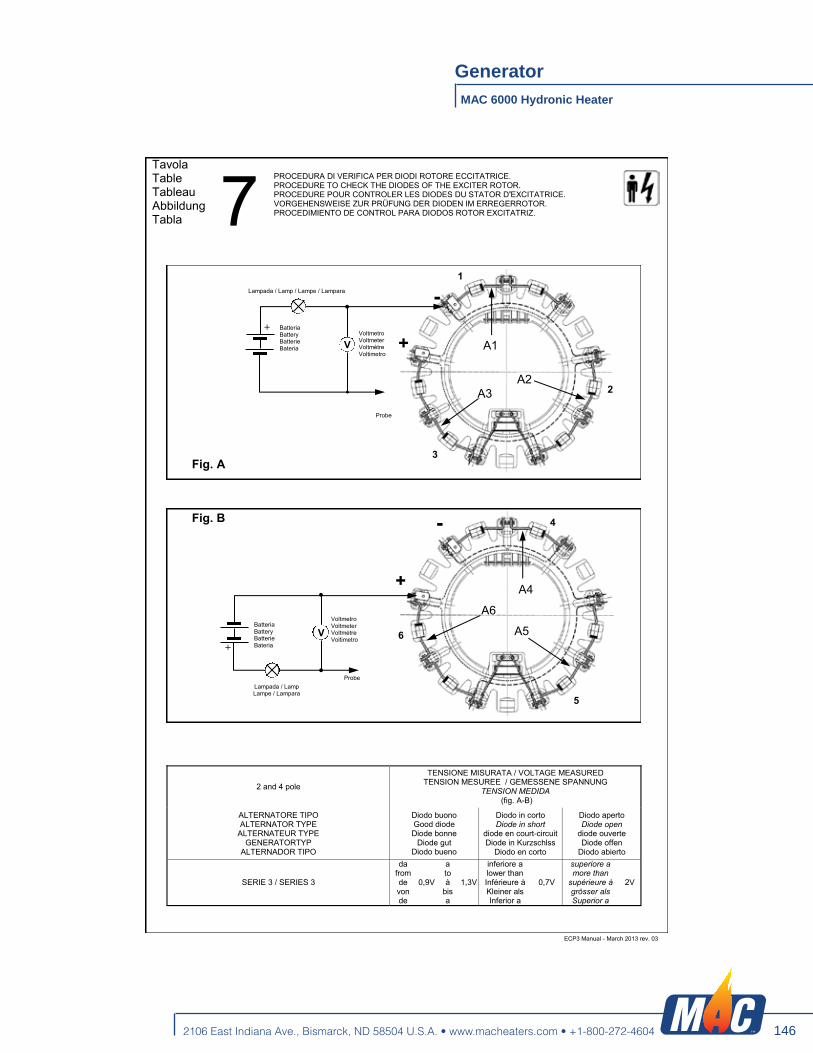
146
MAC 6000 Hydronic Heater
Generator
2106 East Indiana Ave., Bismarck, ND 58504 U.S.A. • www.macheaters.com • +1-800-272-4604
ECP3 Manual - March 2013 rev. 03 41
Tavola Table Tableau Abbildung Tabla 7
PROCEDURA DI VERIFICA PER DIODI ROTORE ECCITATRICE. PROCEDURE TO CHECK THE DIODES OF THE EXCITER ROTOR. PROCEDURE POUR CONTROLER LES DIODES DU STATOR D‟EXCITATRICE. VORGEHENSWEISE ZUR PRÜFUNG DER DIODEN IM ERREGERROTOR. PROCEDIMIENTO DE CONTROL PARA DIODOS ROTOR EXCITATRIZ.
V A1
A2 A3
+
Lampada / Lamp / Lampe / Lampara
Voltmetro Voltmeter Voltmètre Voltimetro
Batteria Battery Batterie Bateria
Fig. A
Probe
+
- 1
2
3
V
A4
A5
A6
+
Lampada / Lamp Lampe / Lampara
Voltmetro Voltmeter Voltmètre Voltimetro
Batteria Battery Batterie Bateria
Probe
Fig. B
+
-
5
6
4
2 and 4 pole
TENSIONE MISURATA / VOLTAGE MEASURED TENSION MESUREE / GEMESSENE SPANNUNG
TENSION MEDIDA (fig. A-B)
ALTERNATORE TIPO ALTERNATOR TYPE
ALTERNATEUR TYPE GENERATORTYP
ALTERNADOR TIPO
Diodo buono Good diode Diode bonne
Diode gut Diodo bueno
Diodo in corto Diode in short
diode en court-circuit Diode in Kurzschlss
Diodo en corto
Diodo aperto Diode open
diode ouverte Diode offen
Diodo abierto
SERIE 3 / SERIES 3
da from de von de
0,9V
a to à
bis a
1,3V
inferiore a lower than Inférieure à Kleiner als Inferior a
0,7V
superiore a more than
supérieure à grösser als Superior a
2V

147
MAC 6000 Hydronic Heater
Generator
2106 East Indiana Ave., Bismarck, ND 58504 U.S.A. • www.macheaters.com • +1-800-272-4604
ECP3 Manual - March 2013 rev. 03 42
Tavola Table Tableau Abbildung Tabla 8 SCATOLA REGOLAZIONE ECP3 ECP3 TERMINAL BOX BOITIER DE REGULATION ECP3 REGLERKASTEN ECP3 CAJA DE REGULATION ECP3
Tavola Table Tableau Abbildung Tabla 9 VOLUMI D‟ARIA E RUMOROSITA‟ (PRESSIONE SONORA (A) A VUOTO)
AIR FLOW AND NOISE LEVEL (NO LOAD (A) SOUND PRESSURE LEVEL) VOLUME D‟AIR ET NIVEAU SONORE (NIVEAU SONORE (A) à VIDE) LUFTMENGE UND GERÄUSCHPEGEL (LAUTSTÄRKE (A) BEI LEERAUF) VOLUMEN DE AIRE Y RUIDO (PRESION SONORA (A) EN VACIO)
MOMENTI DI INERZIA E PESI MOMENTS OF INERTIA AND WEIGHTS MOMENT D‟INERTIE ET POIDS TRAGHEITSMOMENT UND GEWICHT MOMENTO DE INERCIA Y PESO
Tipo Type Typ
Volume d‟aria Air volume
Volume d‟air Luftmenge
Volumen de aire
Rumore Noise Bruit
Gerausch Ruido
Rumore Noise Bruit
Gerausch Ruido
Tipo Type Typ
Volume d‟aria Air volume
Volume d‟air Luftmenge
Volumen de aire
Rumore Noise Bruit
Gerausch Ruido
Rumore Noise Bruit
Gerausch Ruido
m3/min 3000 3600 m3/min 1500 1800
7m 1m 7m 1m 7m 1m 7m 1m 3000 RPM 3600 RPM dBA dBA dBA dBA 1500 RPM 1800 RPM dBA dBA dBA dBA
ECP3-1S/2 6,4 7,8 70 85 73 89 ECP3-1S/4 3,5 3,9 58 72 60 78 ECP3-2S/2 6,3 7,8 70 85 73 89 ECP3-2S/4 3,5 4,1 58 72 60 78 ECP3-3S/2 6,2 7,8 70 85 73 89 ECP3-3S/4 3,3 4 58 72 60 78 ECP3-1L/2 6 7,2 70 85 73 89 ECP3-1L/4 3 3,5 58 72 60 78 ECP3-2L/2 5,8 6,8 70 85 73 89 ECP3-2L/4 3 3,5 58 72 60 78
Tipo Type Typ
J
Peso Weight Poids
Gewicht
Kgm² Kg
FORMA / FORM / FORME FORMA / FORM / FORME
B3/B14 B3/B9 MD35 B3/B14 B3/B9 MD35
ECP3-1S/2 0,03561 0,03549 0,03591 52 50 56
ECP3-2S/2 0,03955 0,03943 0,03985 58 56 62
ECP3-3S/2 0,04564 0,04568 0,04594 64 62 68
ECP3-1L/2 0,05148 0,05144 0,05187 76 74 80
ECP3-2L/2 0,05735 0,05731 0,05774 84 82 88
Tipo Type Typ
J
Peso Weight Poids
Gewicht
Kgm² Kg
FORMA / FORM / FORME FORMA / FORM / FORME
B3/B14 B3/B9 MD35 B3/B14 B3/B9 MD35
ECP3-1S/4 0,05231 0,05219 0,05261 56 54 59
ECP3-2S/4 0,05933 0,05921 0,05963 62 60 65
ECP3-1L/4 0,07231 0,07227 0,07270 76 74 79
ECP3-2L/4 0,08409 0,08405 0,08448 84 82 87
ECP3-3L/4 0,09027 0,09023 0,09066 90 88 93
Tavola Table Tableau Abbildung Tabla 10

148
MAC 6000 Hydronic Heater
Generator
2106 East Indiana Ave., Bismarck, ND 58504 U.S.A. • www.macheaters.com • +1-800-272-4604
ECP3 Manual - March 2013 rev. 03 43
dimensions in mm
DIMENSIONI DI INGOMBRO OVERALL DIMENSIONS ENCOMBREMENT BAUBMESSUNGEN DIMENSIONES EXTERNAS
Flangia / Flange /Bride Flansch / Bridas
SAE N°
O P Q n° fori
6 308 266,7 285,75 8 22°30’
5 356 314,3 333,4 8 22°30’
4 403 362 381 12 15°
3 451 409,6 428,6 12 15°
Giunti a dischi Disc coupling
Disque de monopalier Scheibenkupplung
Juntas a discos SAE N°
L d Q1 n° fori S1
6 ½ 30,2 215,9 200 6 9 60°
7 ½ 30,2 241,3 222,25 8 9 45°
8 62 263,52 244,47 6 11 60°
10 53,8 314,32 295,27 8 11 45° 11 ½ 39,6 352,42 333,37 8 11 45°
Forma Form Forme
A B C E F
B14 S 498 440 301 - - L 568 510 371 - -
B9 S 440 - 301 - - L 510 - 371 - -
J609b S 440 - 301 146,1
163,6 177,8
165,1 196,8 196,8 L 510 - 371
S 454 - 305 - MD35
L 524 - 375 - -
Centro di gravità Center of gravity Centre de gravité
Schwerpunkt Centros de gravedad
2 Poli - Pole - Polig - Polos
Forma Form Forme
1S 2S 3S 1L 2L
B14 239 233 220 267 256
B9 243 237 223 274 261
J609b 245 239 225 275 262
MD35 237 232 221 271 260
Centro di gravità Center of gravity Centre de gravité
Schwerpunkt Centros de gravedad
4 Poli - Pole - Polig - Polos
Forma Form Forme
1S 2S 1L 2L 3L
B14 237 228 270 256 249
B9 241 231 277 261 254
J609b 243 232 278 262 255
MD35 235 228 273 261 255
Tavola Table Tableau Abbildung Tabla 11

149
MAC 6000 Hydronic Heater
Generator
2106 East Indiana Ave., Bismarck, ND 58504 U.S.A. • www.macheaters.com • +1-800-272-4604
MECC ALTE SPA via Roma, 20 - 36051 Creazzo (VI)
Tel +39 0444 396111 - Fax +39 0444 396166 e-mail : [email protected] sito web : www.meccalte.com
FAR EAST MECC ALTE (F.E.) PTE LTD
19 KIAN TECK DRIVE SINGAPORE 628836
TEL. +65 62 657122 FAX +65 62 653991 e-mail : [email protected]
AUSTRALIA MECC ALTE ALTERNATORS PTY LTD
10 DUNCAN ROAD, PO BOX 1046 DRY CREEK, 5094 SOUTH AUSTRALIA
TEL. +61 08/83498422 FAX +61 08/83498455 e-mail : [email protected]
FRANCE MECC ALTE INTERNATIONAL S.A.
Z.E.LA GAGNERIE 16330 ST.AMANT DE BOIXE
TEL. 0545/397562 FAX 0545/398820 e-mail : [email protected]
CHINA MECC ALTE ALTERNATOR (HAIMEN) LTD
755 NANHAI EAST ROAD JIANGSU HAIMEN ECONOMIC DEVELOPMENT AREA
226100 PEOPLE’S REPUBLIC OF CHINA TEL: 86 513-82325758 FAX: 86 513-82325768
e-mail: [email protected]
INDIA MECC ALTE INDIA PVT LTD
PLOT No. -1, SANASWADI - TALEGAON DHAMDHERE ROAD TALUKA : SHIRUR, DISTRICT : PUNE - 412208
MAHARASHTRA, INDIA TEL. +91 2137 619600 - FAX +91 2137 619699
e-mail : [email protected]
DEUTSCHLAND MECC ALTE GENERATOREN GmbH
ENSENER WEG 21 D-51149 KÖLN
TEL. 0 22 03 / 50 38 10 FAX 0 22 03 / 50 37 96 e-mail : [email protected]
UNITED KINGDOM MECC ALTE U.K LTD 6 LANDS’ END WAY
OAKHAM RUTLAND LE 15 6RF TEL. 1572/771160 FAX 1572/771161
e-mail : [email protected]
ESPAÑA MECC ALTE ESPAÑA S.A.
C/ RIO TAIBILLA, 2 POLIG. IND. LOS VALEROS
03178 BENIJOFAR (ALICANTE) TEL. 096/6702152 FAX 096/6700103
e-mail : [email protected]
U.S.A. AND CANADA Mecc Alte Inc.
1229 Adams Drive McHenry, Il. 60051
Tel. 815-344-0530 Fax.815-344-0535 Email : [email protected]
Mar
ch 2
013
- rev
.03

150
MAC 6000 Hydronic Heater
Riello Burner
2106 East Indiana Ave., Bismarck, ND 58504 U.S.A. • www.macheaters.com • +1-800-272-4604
Installation & Operating Manual
2902453 (2) - 07/2008
Single stage operation oil burner
CODE MODEL TYPE
3726512 F20 WITH HYDRAULIC JACK 265T
NON-RETROFIT APPLICATIONSIf this burner is being installed in a packaged unit (ie. burner comes with a boiler or furnace), followthe installation and set-up instructions supplied with the heating unit, as settings may differ fromthose shown in this manual.- The following pages contain information, descriptions and diagrams for the proper installation
and wiring of the burner. Please read carefully before attempting final installation.- This manual is to remain with the final installation designation. It is the installer’s responsibility to en-
sure that the burner installation and operation instructions mentioned in this manual are followed andoperated within local code authority limits.

151
MAC 6000 Hydronic Heater
Riello Burner
2106 East Indiana Ave., Bismarck, ND 58504 U.S.A. • www.macheaters.com • +1-800-272-4604
2453
GB
INSTALLLATION PRECAUTIONS
AIR FOR COMBUSTIONDo not install burner in room with insufficient air for combustion. Be sure there is an adequate air supply forcombustion if the boiler/furnace room is enclosed. It may be necessary to create a window to permit suffi-cient air to enter the boiler/furnace room. The installer must follow local ordinances in this regard. CANADA It is suggested that the installer follow CSA standard B139.USA It is suggested that the installer follow NFPA manual #31.
CHIMNEYBe sure chimney is sufficient to handle the exhaust gases. It is recommended that only the burner be con-nected to the chimney. Be sure that it is clean and clear of obstructions.
OIL FILTERAn external oil filter is REQUIRED, even though there is an internal strainer in the pump. The filter should bereplaced at least once a year, and the fil ter container should be thoroughly cleaned prior to installing a newfilter cartridge.
DRAFTFollow the instructions furnished with the heating appliance. The pressure in the combustion area should bekept as close to zero as possible. The burner will operate with a slight draft or pressure in the chamber.
ELECTRICAL CONNECTIONSCANADA All electrical connections should be done in accordance with the C.E.C. Part 1, and all local codes.
The system should be grounded.USA All electrical connections should be done in accordance with the National Electrical Code, and all
local ordinances. The system should be grounded.
CONTROL BURNER OPERATIONCheck out the burner and explain its operation to the homeowner. Be sure to leave the Owner’s Instructionsheet with the homeowner.
FIRE EXTINGUISHERIf required by local codes, install an approved fire extinguisher.
ELECTRICAL CONNECTIONSIn most localities, a number 14 wire should be used inside a metal conduit. The system should be grounded.A service switch should be placed close to the burner on a fireproof wall in an easily accessible location.

152
MAC 6000 Hydronic Heater
Riello Burner
2106 East Indiana Ave., Bismarck, ND 58504 U.S.A. • www.macheaters.com • +1-800-272-4604
24531
GB
PACKAGE CONTENTS LISTYour Riello 40 burner should include the following parts. Please check to make sure all parts are present before begin-ning the installation.
SERIAL NUMBER IDENTIFICATION Your Riello burner may have been manufactured in more than one location and therefore there are two possible serialnumber identification.The Riello 9 character serial number, example, 06 01 12345, is identified as follows: 06 = Last two digits of the year of manufacture; 01 = Week of manufacture; 12345 = Increment of 1 for each burner produced – specific
to product code – reset to zero each January 1st.
The Riello 15 character serial number, example, 06 A 8511111 00025, is identified as follows: 06 = Last two digits of the year of manu-
facture; A = BI-week of manufacture; 8511111 = Burner product code;00025 = Increment of 1 f or each burner pro-
duced – specific to product code –reset to zero each January 1st.
Quantity Description Code1 Burner chassis with cover 37265121 Universal mounting flange + mounting gasket 25673951 Parts bag 25662831 Parts bag 25673381 Installation manual 29024531 By-pass plug
1Separate carton - OEM burners shipped with combustion head mountedAir Tube/Drawer Assembly
Parts bag 2566283 Parts bag 2567338Quantity Description Quantity Description
1111222
Female 1/4” NPT adapterMale 3/8” NPT adapterOil pump connector (supply)Oil pump connector (return)Mounting flange bolts (short)NutsChrome nuts
2222
Semi-flange bolts (long)Semi-flangeCover screwsNuts
(06) (01) (12345)
Year ofmanufacture
Week ofmanufacture Increment
(06) (A) (8511111) (00025)
Year ofmanufacture
Burnerproduct code IncrementBI-week of
manufacture

153
MAC 6000 Hydronic Heater
Riello Burner
2106 East Indiana Ave., Bismarck, ND 58504 U.S.A. • www.macheaters.com • +1-800-272-4604
24532
GB
TECHNICAL DATASPECIFICATIONS
BURNER AND MOUNTING FLANGE DIMENSIONS
E1: 10-inch long (254mm) tubes are also available.
BURNER COMPONENTS IDENTIFICATION
Fuel No. 2 Fuel OilFiring rate 3.50 to 6.40 GPH 11.3 to 20.7 kg/h
Effective output 490,000 to 896,000 BTU/h - 143.5 to 262.5 kW 123,480 to 225,790 kcal/h
Voltage (single phase) 120V 60Hz (+ 10% - 15%)Absorbed electrical power 465 WattsMotor (rated) 3250 rpm Run Current 4.3 AMPCapacitor 16 Microfarads 260VPump pressure 100 to 200 psiPrimary control RIELLO 530 SE/C 24VIgnition transformer 8kV 16mA
Model F20 A B C D E F G H I LInches 11 3/4 13 25/32 9 1/16 4 11/16 5 11 27/32 1 1/2 1/4 7/16 2 7/8mm 298 350 230 119 127 301 38 6 11 73
D8860
B
A
E FE1
C
D
18 5 19 14 23
1
21
4 3 2
6
22
15
16
14
13
17
9
8
12 11 10
7
BURNER COMPONENTS1 Pressure gauge connection port2 Return fuel line port3 Inlet fuel line port4 Capillary tube5 Adjustable collar6 Mounting flange with gasket7 Air adjustment fixing screws8 Hydraulic air shutter9 Capacitor
10 Fuel pressure adjustment screw low fire
11 Hydraulic delay valve low fire start12 Motor
13 Pump pressure regulator adjust-ment screw
14 Primary control sub-base15 Lockout indicator lamp and reset
button16 Primary control17 Hydraulic jack18 End cone19 Turbulator adjustment screw20 Air tube cover21 Coil22 Vacuum gauge connection port23 24V thermostat connections
6 17/32”-166mm
8 1/4” - 210 mm
9 1/4” - 235 mm
7 7/
8” -
200
mm
4 31
/ 32”
126
mm
60°45°
30° H IG
L
D6000
D8806

154
MAC 6000 Hydronic Heater
Riello Burner
2106 East Indiana Ave., Bismarck, ND 58504 U.S.A. • www.macheaters.com • +1-800-272-4604
24533
GB
INITIAL SET-UPA) Remove burner and air tube from cartons. Check parts list (inside cover) to ensure all parts are present.B) Remove burner cover by loosing the three screws securing it. Remove control box and air tube cover.C) Remove drawer assembly from air tube, insert nozzle and set Turbulator adjustment for specific input required, then
set aside.D) Mount air tube to burner chassis.
ASSEMBLY OF AIR TUBE TO BURNER CHASSISThe air tube and drawer assembly areshipped in a carton separate from theburner chassis. Choose the proper airtube length to obtain the tube insertion forthe specific installation.A) Remove the AIR TUBE and B URNER
CHASSIS from their respectivecartons.
B) Remove the DRAWE R ASSEMBLY(1) from inside the AIR T UBE byloosening the screw (2). Carefully pullthe DRAWER ASSEMBLY out of the AIR TUBE, install the required nozzle (see page 7) and set aside.
C) Align the two holes on the AIR TUBE HOLDING PLA TE (5) with the two holes left o pen on the BURNERCHASSIS FRONT PLATE (4) with the BOLTS (3) removed.Replace the BOLTS and finger tighten only. Re-install DRAWER ASSEMBLY into AIR TUBE. Tighten SCREW(2) securely (see page 7).
D) Tighten the two bolts (3) securely.
MOUNTING THE BURNER TO THE BOILER OR FURNACEThere are three possible methods to mount the burner, depending on the individual application. These are:1) Universal flange bolted to Boiler/Furnace unit.2) Semi-flange collar bolted to Boiler/Furnace unit.3) Universal flange mounted to optional Pedestal mount, where flange mounting direct to appliance is not possible.
Pedestal kit must be ordered separately.
METHOD 1 – UNIVERSAL MOUNTING FLANGE
S7445
S7439
A
B
A
B
DRY BASEBOILER
D6013
D6014
COMBUSTIONCHAMBER

155
MAC 6000 Hydronic Heater
Riello Burner
2106 East Indiana Ave., Bismarck, ND 58504 U.S.A. • www.macheaters.com • +1-800-272-4604
24534
GB
A) Insert the two BOLTS (1) into the UNIVERSAL MOUNTING FLANGE (10) from the flat side, ensuring the boltheads are flush with the flat surface. Secure in place using two special CHROME NUTS (2) provided.
B) Position the MOUNTING GASKET (3) between the flat surface of the UNIVERSAL MOUNTING FLANGE (10)and the appliance. Line up the holes in the UNIVERSAL MOUNTING FLANGE with the STUDS (4) on the ap-pliance mounting plate and securely bolt the UNIVERSAL MOUNTING FLANGE to the plate.
C) Secure the two semi-flanges of the ADJUSTABLE COLLAR (9) to the AIR TUBE using the two long BOLTS (6). Be sure that the ADJUSTABLE collar is properly positioned so the outside edge of the END CONE will be atleast 1/4 inch (6.5 mm) back from the inside wall of the refractory of the combustion chamber (see dimensionB). The measured length (A), is to include MOUNTING GASKET and FLANGE, if used.
D) The burner may now be attached to the heating unit by inserting the AIR TUBE through the BURNER ACCESSHOLE (8) and into the appliance, making sure the BOLTS (1) line up with the two HOLES (5) in the ADJUSTABLECOLLAR. Secure the burner in place using two NUTS (7).
A visual verification of the air tube insertion into the combustion chamber of the heating unit is suggested. Dimension B should be at least 1/4” (see drawing).
NOTE:A suggested method for creating mounting bolt holes in the mounting gasket: Hold the gasket against the appli-ance mounting bolts using the mounting flange for proper positioning. Lightly tap the flange with a hammer toform the holes.
METHOD 2 – SEMI-FLANGE COLLARA) Follow item C from METHOD 1.B) Align the air tube and attached adjustable collar so air tube is centered in the burner access hole of the boil-
er/furnace unit. Mark the center of the two holes in the ADJUSTABLE COLLAR on to the front plate of theheating unit. Then drill 1/4 inch (6.5 mm) holes through the front plate of the unit, using marks as a guide.
C) Install two short BOLTS (1) through the front plate of the heating unit from the inside, and secure on the out-side using the two special CHROME NUTS (2).
D) Follow item D from METHOD 1.
METHOD 3 – PEDESTAL MOUNTSecure the MOUNTING FLANGE to MOUNTING PEDESTAL using the hardware provided with the pedestal.Secure burner to MOUNTING FLANGE as in METHOD 1, items A, C and D.NOTE: It is suggested that the pedestal be anchored in position on the floor by installing brackets over the pedestaltube and securing brackets to the floor.
WARNING: WHEN THE COMBUSTION CHAMBER IS LINED WITH A REFRACTORY MATERIAL, IT IS IMPERATIVETHAT THE END CONE NOT PROTRUDE INTO THE CHAMBER AREA, AS EXCESSIVE HEAT AT BURNERSHUT-DOWN WILL DAMAGE THE END CONE.

156
MAC 6000 Hydronic Heater
Riello Burner
2106 East Indiana Ave., Bismarck, ND 58504 U.S.A. • www.macheaters.com • +1-800-272-4604
24535
GB
ELECTRICAL CONNECTIONSIt is advisable to leave the control box off the sub-base whilecompleting the electrical connections to the burner.1) Wire access hole (Use BX electrical connector)2) Earth ground conductor terminal (GREEN WIRE)3) Hot conductor terminal (BLACK WIRE)4) Neutral conductor terminal (WHITE WIRE)5) Strain relief clamp
The burner may be controlled using either a DIRECT LINEVOLTAGE control circuit (120V AC 60 cycle) OR a LOW VOLTAGE thermostat input (T-T). Using the appropriate diagram below, make electrical connections to burner. All wiring must be done in accordance withexisting electrical codes, both national and local. When all electrical connections have been made, the control box may be put back in place on the sub-base.
APPLICATION FIELD WIRING
WARNING:The hot (black) wire must be connected to the L terminal and theneutral (white) wire must be connected to the N terminal or theprimary safety control will be damaged. Do not connect wither wire to the terminal marked .
WARNING: DO NOT activate burner until proper oil line connections have been made, or failure of the pumpshaft seal may occur.
S7436
T
TJ
T
T
1 2 3 4 5 6 7 8 9
AC
120 V
AC
120 V
D8794
FACTORYWIRED
SUB-BASE
EA
RTH
GR
OU
ND
(G
REE
N)
NE
UTR
AL
(WH
ITE
)
HO
T LI
NE
(BLA
CK
)
24V OPERATING
N L
LINE SAFETYSWITCH
OPERATINGLIMIT SWITCH
SAFETYLIMIT SWITCH
FUSE 15A
N L N L
EA
RTH
GR
OU
ND
(G
REE
N)
NE
UTR
AL
(WH
ITE
)
HO
T LI
NE
(BLA
CK
)
FUSE 15A
LINE SAFETYSWITCH
SAFETYLIMIT SWITCH LIMIT SWITCH
ON LEFT SIDE OFTHE CONTROL BOX
ON LEFT SIDE OFTHE CONTROL BOX
Blu
e
Whi
te
Bla
ck
Bro
wn
Whi
te
Blu
e
Bro
wn
Black
CAPACITOR
MOTOR
COIL
Black
Whi
te
DIRECT LINE LOW VOLTAGEVOLTAGEREMOTE SENSING OFSAFETY LOCKOUT:The SAFETY SWITCH inthe 530SE/C 24V CON-TROL BOX is equippedwith a contact allowing re-mote sensing of burnerlockout.The electrical connectionis made at terminal 4 ( )on the SUB-BASE.Should lockout occur the530SE/C 24V CONTROLBOX will supply a powersource of 120Vac to theconnection terminal.The maximum allowablecurrent draw on this termi-nal (4) is 1 Amp.
WARNING: If a neutral or groundlead is attached to thisterminal, the CONTROLBOX on the burner willbe damaged shouldlockout occur.

157
MAC 6000 Hydronic Heater
Riello Burner
2106 East Indiana Ave., Bismarck, ND 58504 U.S.A. • www.macheaters.com • +1-800-272-4604
24536
GB
NOZZLE PLACEMENTA) Determine the proper firing rate for the boiler or furnace
units, considering the specific application, and then use theBurner Setup Charts to select the proper nozzle and pumppressure to obtain the required input from the burner.
B) Remove the NOZZLE ADAPT ER (2) from the DRAWERASSEMBLY by loosening the SCREW (1).
C) Insert the proper NOZZLE into the NOZZLE ADAPTER andtighten securely (Do not over tighten).
D) Replace adapter, with nozzle installed, into drawer assem-bly and secure with screw (1).
INSTALLATION/REMOVALOF DRAWER ASSEMBLYA) To remove drawer assembly,
loosen SCREW (3), then unplugCONTROL BOX (1 ) by carefullypulling it back and then up.
B) Remove the AIR TUBE COVERPLATE (5) by loosening the tw oretaining SCREWS (4).
C) Loosen SCREW (2), then slidethe complete drawer assemblyout of th e combustion head asshown.
D) To insert drawer assembly,reverse the procedure in items Ato C above, then attach fuel lineto the pump.
ELECTRODE SETTINGIMPORTANT:These dimensions must be observed and verified.
TURBULATOR SETTINGA) Loosen NUT (1), then turn SCREW (2) until the INDEX MARK-
ER (3) is aligned with the correct index number as per theBurner Set-up chart.
B) Retighten the RETAINING NUT (1).
NOTE:Zero and five are scale indicators only. From left to right, the firstline is 5 and the last line 0.
S7437
S7438
5/32” or 4 mm
1/4” to 9/32” or 6 to 7 mm
13/6
4”5
mm
D6003
3
2
1D5997

158
MAC 6000 Hydronic Heater
Riello Burner
2106 East Indiana Ave., Bismarck, ND 58504 U.S.A. • www.macheaters.com • +1-800-272-4604
24537
GB
OIL LINE CONNECTIONSWARNING:The burner is shipped from the factory with the pump set to operate on a TWO line system.
NOTE:- THIS BURNER MUST BE INSTALLED WITH A TWO LINE SYSTEM TO ALLOW THE HYDRAULIC DELAY
VALVE TO OPERATE.- Pump pressure must be set at time of burner start-up. A pressure gauge is attached to the PRESSURE PORT
(1) for pressure readings.
Two PIPE CONNECTORS (2) are supplied with the burner for connection to either a single or a two-pipe system.Also supplied are two adapters (3), two female 1/4” NPT, to adapt oil lines to burner pipe connectors. All pump por t threads are British Parallel thread design. Direct connection of NPT thre ads to the pump willdamage the pump body. Riello manometers and vacuum gauges do not require any adapters, and can be safely connected directly to pumpports. An NPT (metric) adapter must be used when connecting other gauge models.
NOTE:If the pump cover (4) is removed for any reason, be sure the O-ring (5), is properly seated in the pump cover (4)before re-attaching the pump cover to the pump housing.
5
41
2
3
7 6 D6180

159
MAC 6000 Hydronic Heater
Riello Burner
2106 East Indiana Ave., Bismarck, ND 58504 U.S.A. • www.macheaters.com • +1-800-272-4604
24538
GB
TWO LINE (LIFT SYSTEM)A) The burner is shipped with the pump set to oper-
ate on a two line system. Suction and return lines(6 & 7 in drawing on page 7) should be the samediameter and both sho uld extend to th e samedepth inside the fuel tank. Be sure there are no air leaks or blockages in thepiping system. Any obstructions in the return linewill cause failure of the pump shaft seal. Do not ex-ceed the pipe lengths indicated in the table.
B) Attach the two PIPE CONN ECTORS (2) to thepump SUCTION and pump RETURN PORT S (6and 7). Attach the required piping to these two p ipe con-nectors using the NPT/METRIC ADAPTERS thatare supplied with the burner.
PUMP PURGETWO LINE (GRAVITY OR LIFT SYSTEM)Turn off the main power source to the burner and re-move the air tube cover. Shine a light source on thephoto cell on the control box (now visible where the airtube cover was removed ), return power to the burnerand activate the burner.With the light source in place, the burner will operate inprepurge only.When the pump is sufficiently purged, the hydraulic airshutter will open.Once the burner is purged, turn off the power sourceand replace the air tube cover. Return power to theburner. The burner is now ready to operate.
NOTE: To protect the pump gears, it is advisable to lubri-cate the pump prior to purging a lift system. Apply oil through the VACUUM PORT (A).
WARNING: - Pipe dope or Teflon tapes are NOT to be used on
any direct oil connection to the fuel pump.- The height ‘P’ in Pipe Length Charts should not
exceed 13 feet (4 m).- The vacuum should not exceed 11.44 inches of
mercury.
IMPORTANT: An external, appropriately listed and certified oilfilter must be placed in the fuel line between thefuel tank and the burner pump.
ATTENTION:It is important that the fuel line be completely sealed and free from air leaks or any internal blockages.WARNING!WHEN THE BYPASS PLUG IS INSTALLED, A TWO PIPE SYSTEM MUST BE USED OR FAILURE OF THEPUMP SHAFT SEAL WILL OCCUR.
2 LINE (LIFT) SYSTEM - PIPE LENGTHSH 3/8” OD 1/2” OD
Feet Meters Feet Meters Feet Meters0 0.0 115 35 330 100
1 1/2 0.5 100 30 330 1003 1.0 80 25 330 1005 1.5 65 20 295 90
6 1/2 2.0 50 15 230 709 1/2 3.0 25 8 100 30
11 3.5 20 6 65 20
D6008
HP
H
ATTENTION:do not exceedpipe lengths
indicated in chart!
A
D6181

160
MAC 6000 Hydronic Heater
Riello Burner
2106 East Indiana Ave., Bismarck, ND 58504 U.S.A. • www.macheaters.com • +1-800-272-4604
24539
GB
AIR SHUTTER SETTINGLOW FIRE SETTINGA) Loosen PRESSURE RELEASING SCREW (1). (One turn is sufficient). This permits the fuel pressure to bleed off
to the pump return port and the burner to operate continuously at the low fire rate.B) Loosen RETAINING NUT (2).C) Turn the ADJUSTING SCREW (3) until the top of the air shutter (9) is correctly positioned according to the Burner
Set-up Chart, column 5, on page 12.D) Use instruments to establish the proper settings for maximum CO2 and a smoke reading of zero.E) Hold ADJUSTING SCREW (3) in position and secure by tightening RETAINING NUT (2).F) Retighten PRESSURE RELEASE SCREW (1).
Note:The low fire pressure regulator is pre-set at the factory to 100 PSI (7 bar). To vary or regulate this pressure it is necessary to attach a pressure gauge to the PRESSURE PORT (6). Loosen the PRESSURE RELEASE SCREW (1) as in step A above. Regulate the pressure by turning the PRESSUREREGULATING SCREW (5).The corresponding pressure can be read on the pressure gauge attached to the PUMP PRESSURE PORT (6).
MAIN FLAME SETTINGA) Be sure that the burner is operating at high fire.B) Set the pump pressure by attaching a pressure gauge to the Pressure port (6) and adjust the pressure by turning
the pressure regulator adjustment screw (10).Loosen the RETAINING NUT (7), and turn the BOLT (8) in a counterclockwise direction until about 3/4 of an inchof thread is visible. Using the setting taken from the Burner Set-up Chart, column 5, position the air shutter (9) sothat the top of the shutter is aligned with the proper index line indicated on the air intake side of the burner housing. Holding the shutter in this position, turn ADJUSTING BOLT (8) in a clockwise direction until a resistance is met.
C) The final position of the air adjustment plate will vary on each installation. Use instruments to establish the propersettings for maximum CO2 and a smoke reading of zero.
NOTE:Variations in flue gas, smoke, CO2 and temperature readings may be experienced when the burner cover is put inplace. Therefore, the burner cover must be in place when making the final combustion instrument readings, to en-sure proper test results.
2
3
8
7
9
6
1 5S7440
D1874
10

161
MAC 6000 Hydronic Heater
Riello Burner
2106 East Indiana Ave., Bismarck, ND 58504 U.S.A. • www.macheaters.com • +1-800-272-4604
245310
GB
BURNER SET-UP CHARTNON-RETROFIT APPLICATIONSIf this burner is being installed in a packaged unit (ie. burner comes with a boiler or furnace), follow theinstallation and set-up instructions supplied with the heating unit, as settings will differ from those shownin this manual.
NOZZLES RECCOMANDED:Monarch R-PLP, Delavan W-B, Danfoss S-B, Steinen SS-S, Hago P.
NOTE:A 45° degree nozzle is sugg ested, however, a 6 0° degree nozzle may be u sed in cases where the flam e isunstable at light-off when operated at low ambient temperatures.
1 2 3 4 5ActualFiring
Rate ± 5%
NozzleSize
PumpPressure Turbulator
Setting
Air DamperSetting
GPH Kg/h GPH PSI bar Low Fire Main Flame3.50 11.3 2.50 x 45°/60° 190 13.0 0.0 2.3 2.84.00 12.9 3.00 x 45°/60° 178 12.0 1.0 2.5 3.24.65 15.0 3.50 x 45°/60° 178 12.0 2.0 2.8 3.75.30 17.1 4.00 x 45°/60° 178 12.0 3.0 3.2 4.56.00 19.4 4.50 x 45°/60° 178 12.0 4.0 3.5 5.06.40 20.7 5.00 x 45°/60° 165 11.4 5.0 3.8 6.0

162
MAC 6000 Hydronic Heater
Riello Burner
2106 East Indiana Ave., Bismarck, ND 58504 U.S.A. • www.macheaters.com • +1-800-272-4604
245311
GB
DUCTED COMBUSTION AIR INTAKE APPLICATIONSThe “Ducted combustion air intake kit” (see P.N. 3002762 in the spare parts list - OPTIONAL), allows ducting of exter-nal air directly into the burner. A 4” diameter air intake is provided in the kit.
The settings of the burner must be according to the BURNER SETUP CHART – AIR INTAKE APPLICATIONS below.
NOZZLES RECCOMANDED:Monarch R-PLP, Delavan W-B, Danfoss S-B, Steinen SS-S, Hago P.
NOTE:A 45° degree nozzle is sugg ested, however, a 6 0° degree nozzle may be u sed in cases where the flam e isunstable at light-off when operated at low ambient temperatures.
NOTES:A) This kit is not suitable for direct vent applications.B) Always try to minimize the length of the air intake pipe.C) Reduce pipe length by 10 feet for every 90° elbow, 5 feet for every 45° elbow.D) Reduce pipe length by 6 feet for the 4” to 6” pipe adapter (if used).E) Air intake venting should be insulated 10 feet from air intake source with a minimum R7 foil lined insulation, to prevent
condensation or corrosion of air intake venting.F) Use an approved type of air intake vacuum breaker and install it in the same room of the burner.
This device should be tested to prove that the vacuum breaker balancer is set correctly and, in the event of intake airsource being blocked, can provide enough combustion air for the burner. If the room where the burner is installedcannot provide enough air or air quality is a concern, an additional air inlet source must be provided to this room.
G) On the outside of the wall, use an approved intake air hood, located above the snow line and in such way as to preventleaves and/or other debris from blocking the air flow. Refer to local codes for proper location of inlet.
COMBUSTION CHAMBERFollow the instructions furnished by the boiler/furnace manufacturer. Size retrofit application according to the appropriateinstallation codes (eg. CSA B139 or NFPA #31).
To mount this kit on the burner, please follow the installation description given in the kit instruction sheet.Use a 4” to 6” pipe adapter (not supplied in the kit) to use a 6” diameter pipe.
Low fire Main flame Low fire Main flame Low fire Main flame Low fire Main flame
3.50 2.50 x 45°/60° 195 0.5 2.3 2.9 2.3 2.9 2.3 3..0 2.5 3.04.00 3.00 x 45°/60° 177 2.0 2.4 3.1 2.4 3.3 2.4 3.5 2.6 3.84.65 3.50 x 45°/60° 176 3.5 2.9 3.9 3.0 4.2 3.0 4.5 3.5 5.05.16 4.00 x 45°/60° 160 5.0 3.1 4.8 3.2 5.0 3.3 5.0 3.8 5.8
Low fire Main flame Low fire Main flame Low fire Main flame Low fire Main flame
3.50 2.50 x 45°/60° 195 0.5 2.1 2.8 2.1 2.8 2.1 2.9 2.1 2.94.00 3.00 x 45°/60° 177 2.0 2.2 3.0 2.2 3.0 2.3 3.1 2.3 3.14.65 3.50 x 45°/60° 176 3.5 2.7 3.4 2.7 3.5 2.9 3.8 3.1 4.55.30 4.00 x 45°/60° 160 4.5 3.0 3.8 3.0 4.0 3.0 4.1 3.1 4.56.00 4.50 x 45°/60° 177 5.0 3.0 5.3 3.3 5.4 3.3 5.4 3.5 5.7
Air Setting Air Setting Air Setting Air Setting
20 Ft. pipe length
50 Ft. pipe length
80 Ft. pipe length
100 Ft. pipe lengthActual
Firing Rate GPH
Nozzle SizePump
Pressure PSI
Head Setting
Air Setting Air Setting Air Setting
MODEL F20 BURNER SETUP CHART with 6" diameter pipe.
Actual Firing Rate
GPHNozzle Size
Pump Pressure
PSI
Head Setting
20 Ft. pipe lengthAir Setting
MODEL F20 BURNER SETUP CHART with 4" diameter pipe.50 Ft.
pipe length80 Ft.
pipe length100 Ft.
pipe length

163
MAC 6000 Hydronic Heater
Riello Burner
2106 East Indiana Ave., Bismarck, ND 58504 U.S.A. • www.macheaters.com • +1-800-272-4604
245312
GB
BURNER START-UP CYCLE
Normal Lock-out, due to light-failure
Thermostat
Motor
Ignition transformer
Valve
Flame
Lock-out lamp
~ 12s ~ 12s ~ 5sD5229

164
MAC 6000 Hydronic Heater
Riello Burner
2106 East Indiana Ave., Bismarck, ND 58504 U.S.A. • www.macheaters.com • +1-800-272-4604
GB
245313
EXPLODED SPARE PARTS LIST

165
MAC 6000 Hydronic Heater
Riello Burner
2106 East Indiana Ave., Bismarck, ND 58504 U.S.A. • www.macheaters.com • +1-800-272-4604
GB
245314
SPARE PARTS LIST
No. CODE DESCRIPTION No. CODE DESCRIPTION
1 3020510 BURNER BACK COVER2 3007077 CRUSHABLE METAL WASHER3 3005771 BANJO CORE ADAPTER - PRESSURE PORT4 3005803 BANJO FITTING - PRESSURE PORT5 3005804 BANJO CORE ADAPTER - RETURN LINE6 3007079 CRUSHABLE METAL WASHER7 3005805 BANJO FITTING - RETURN8 3007028 O-RING - PUMP PRESSURE REGULATOR9 3007202 REGULATOR SCREW
10 3007162 O-RING - PUMP COVER11 3005719 PUMP SCREEN12 3006925 VALVE STEM13 3007203 VALVE STEM PLATE14 3005847 1/4” NPT/ METRIC ADAPTER - FEMALE15 3006571 3/8” NPT/METRIC ADAPTER - MALE16 3007029 O-RING - VALVE STEM UPPER17 3007156 O-RING - VALVE STEM LOWER18 3006995 PIPE CONNECTOR - RETURN19 3007893 BLEEDER20 3006553 COIL U-BRACKET AND KNURLED NUT21 3002279 COIL22 3007806 PUMP23 3006994 PIPE CONNECTOR - SUPPLY24 3000443 PUMP DRIVE KEY25 3005845 MOTOR26 3005858 UNION - NOZZLE TUBE / EXTENSION27 3007318 AIR TUBE COVER28 3006500 HI FIRE DELAY VALVE29 3020487 PRIMARY CONTROL 530SE/C 24V30 3002280 PHOTO-CELL31 3002278 PRIMARY CONTROL SUB BASE32 3005809 OIL PRESSURE TUBE33 3005808 OIL RETURN TUBE34 3005849 SEMI FLANGE35 3005851 UNIVERSAL MOUNTING FLANGE36 3005852 MOUNTING GASKET37 3006499 HYDRAULIC JACK38 3008050 CAPILLARY TUBE39 3000645 HYDRAULIC AIR SHUTTER40 3007211 AIR INTAKE HOUSING41 3005799 FAN42 3005857 NOZZLE OIL TUBE EXTENSION
43 3005846 CAPACITOR 16 µF44 3007358 ACOUSTIC LINER45 3005801 GASKET
OPTIONAL46 3002762 DUCTED COMBUSTION AIR INTAKE KIT
50 3949271 SHORT COMBUSTION HEAD 5” (275T1)51 3005897 TURBULATOR DISC52 3005896 CROSS - CASTING53 3006965 NOZZLE ADAPTER54 3006987 NOZZLE OIL TUBE - SHORT55 3005900 REGULATOR ASSEMBLY - SHORT56 3005902 ELECTRODE ASSEMBLY - SHORT57 3005869 ELECTRODE PORCELAIN58 3005894 END CONE59 3005892 SHORT AIR TUBE
50 3949272 LONG COMBUSTION HEAD 10” (275T2)51 3005897 TURBULATOR DISC52 3005896 CROSS - CASTING53 3006965 NOZZLE ADAPTER54 3006988 NOZZLE OIL TUBE - LONG55 3005901 REGULATOR ASSEMBLY - LONG56 3005903 ELECTRODE ASSEMBLY - LONG57 3005869 ELECTRODE PORCELAIN58 3005894 END CONE59 3005893 LONG AIR TUBE
Technical Support Hotline1-800-4-RIELLO
1-800-474-3556
35 Pond Park RoadHingham, MA 02043Phone 781-749-8292
Toll Free 800-992-7637Fax 781-740-2069
www.riellousa.com
2165 Meadowpine BlvdMississauga, ON L5N 6H6Phone 905-542-0303Toll Free 800-387-3898Fax 905-542-1525
www.riellocanada.com

166
MAC 6000 Hydronic Heater
Riello Burner
2106 East Indiana Ave., Bismarck, ND 58504 U.S.A. • www.macheaters.com • +1-800-272-4604
245315
GB
BURNER START- UP FORM *
35 Pond Park Rd.Hingham, MA 02043Phone: 781-749-8292
Toll Free: 800-992-7637Fax: 781-740-2069
2165 Meadowpine Blvd.Mississauga,On L5H 3R2
Phone: 905-542-0303 Toll Free: 800-387-3898
Fax: 905-542-1525
Burner S/N. or Model:
Installer name:
Company:
Address:
Phone:
Owner Name:
Address:
Phone:
Appliance:
Installation date:
Fax:
E-mail:
Nozzle info: Pump pressure:
Turbolator setting:
Draft overfire: Draft breech:
Air setting:
CO2: CO: O2: Smoke density: (Bacharach)
Single line: Two lines:
Burner Start-up Info (OIL)
* This form was designed and provided in the installation manual for reference and also for providing tech-nical information which can be faxed or mailed to our technical hot-line coordinator when technical assis-tance is required. Please complete this form, fax it or mail it at the address/fax above, or send an e-mailwith the information listed below to: [email protected]

167
MAC 6000 Hydronic Heater
2106 East Indiana Ave., Bismarck, ND 58504 U.S.A. • www.macheaters.com • +1-800-272-4604
Service Record
DATE HOURS SERVICE PERFORMED PERFORMED BY NOTES

168
MAC 6000 Hydronic Heater
2106 East Indiana Ave., Bismarck, ND 58504 U.S.A. • www.macheaters.com • +1-800-272-4604
Service Record
DATE HOURS SERVICE PERFORMED PERFORMED BY NOTES

169
MAC 6000 Hydronic Heater
2106 East Indiana Ave., Bismarck, ND 58504 U.S.A. • www.macheaters.com • +1-800-272-4604
Service Record
DATE HOURS SERVICE PERFORMED PERFORMED BY NOTES

170
MAC 6000 Hydronic Heater
2106 East Indiana Ave., Bismarck, ND 58504 U.S.A. • www.macheaters.com • +1-800-272-4604
Notes

171
MAC 6000 Hydronic Heater
2106 East Indiana Ave., Bismarck, ND 58504 U.S.A. • www.macheaters.com • +1-800-272-4604
Notes

172
MAC 6000 Hydronic Heater
2106 East Indiana Ave., Bismarck, ND 58504 U.S.A. • www.macheaters.com • +1-800-272-4604
Quick Reference/Maintenance Guide
MAC 6000
2106 East Indiana Ave., Bismarck, ND 58504, U.S.A. www.macheaters.com +1.800.272.4604 Page 34
QUICK REFERENCE SERVICE/MAINTENANCE GUIDE This is a quick reference page for your main service/maintenance intervals. More details and further service/maintenance guidelines provided in each components section within this manual.
Isuzu Engine Break-in/oil change intervals: Page……. ISUZU 3CA1 Diesel Engine
50 Hour break-in (NO EXCEPTIONS)o Engine oil, engine oil filter, engine fuel filter changeo Cooling fan V-belt check and adjusto Battery
250 Hour regular intervalso Engine oil and engine oil filtero Radiator fins check and cleano Cooling fan V-belt check and adjusto Governor lever and accelerator check and adjusto Engine air filter clean & inspect
500 Hour regular intervalso Engine air filter changeo Engine fuel filter change
1000 Hour regular intervals or every one (1) yearo Change engine coolant
Page……. Riello Burner
o Burner fuel filter - Every 250 hourso Burner Nozzle - Annually
Page……. Glycol/Tank

2106 East Indiana Ave., Bismarck, ND 58504 U.S.A. • www.macheaters.com • +1-800-272-4604
2106 East Indiana Ave.Bismarck, ND 58504 U.S.A.
www.macheaters.com1-800-272-4604