mac protocols for wsns internet of things (ex reti...
TRANSCRIPT

†Department of Computer Science – University of Rome “Sapienza” – Italy
MAC Protocols for WSNs
Internet of Things (ex Reti Avanzate), a.a. 2015/2016
Un. of Rome “La Sapienza” Chiara Petrioli†

2
S-MAC (Sensor MAC)
W. Ye, J. Heidemann, D. Estrin “An energy efficient MAC Protocol for Wireless Sensor Networks”, IEEE Infocom 2002
Synchronized MAC based on duty cycle

3
Performance objectives
1) Energy efficiency • Sources of energy waste
– collision. When a transmitted packet is corrupted it has to be discarded, and the follow-on retransmissions increase energy consumption. Collision also increases latency as well.
– overhearing, meaning that a node picks up packets that are addressed to other nodes.
– control packet overhead – idle listening, i.e., listening to receive possible traffic that is not
sent (major source of energy consumption).
2) End-to-end latency 3) Fairness 4) Network capacity/scalability (to density and traffic)
4
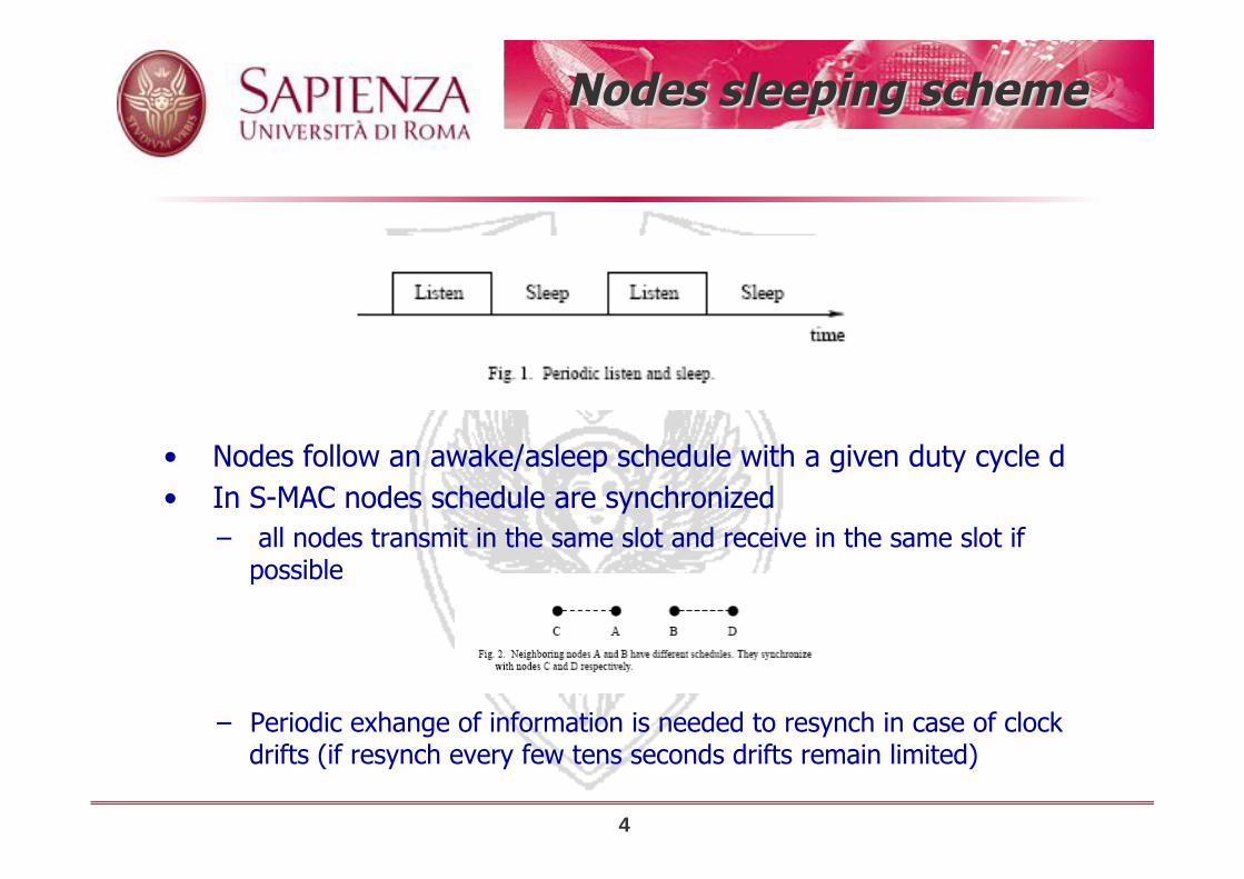
Nodes sleeping scheme
• Nodes follow an awake/asleep schedule with a given duty cycle d • In S-MAC nodes schedule are synchronized
– all nodes transmit in the same slot and receive in the same slot if possible
– Periodic exhange of information is needed to resynch in case of clock drifts (if resynch every few tens seconds drifts remain limited)

5
Choosing and maintaining schedules
• Before a node starts its periodic listen and sleep, it needs to choose a schedule and broadcast it to its immediate neighbors (schedule exchange). – at start up node x listens for some random time
ü if x receives a SYN from another node y it synchronize to its schedule (x is a follower). It waits for a random delay td and rebroadcasts its schedule.
– follower of the same synchronizer do not collide thanks to td
ü otherwise node x selects a random time t to sleep before waking again and send this to neighbors in a SYN (x is a synchronizer)
ü if a node receives a different schedule after it selects its own it adopts both schedule, broadcasting the new one
– “border nodes” where two synch waves meet are the ones with multiple schedules » they consume more energy
• Each node also maintains a schedule table that stores the schedules of all its known neighbors.

6
When a node has a packet to send …
• It waits for the destination to be ON and sends the packet following CSMA/CA – performs carrier sense for a random interval – if no transmission within this interval the floor is taken (physical carrier
sense) to transmit RTS/CTS – if the RTS/CTS is successful (virtual carrier sensing) DATA is sent which
is followed by an ACK – NAVs are used for deciding for how long nodes should go to sleep
before they can try to access again in case neighbors are transmitting – to better exploit the time needed to hanshake (RTS/CTS) bursts of
packets are transmitted if more packets are in queue for the same destination ü Limited packet size and transmission of ACKs following reception avoids
hidden terminal problem if nodes waking up wait for some limited time before transmitting

7
Maintaining synchronization
• Some initially exchanged SYN maybe lost e.g. due to collision, or new nodes maybe added
• Clock drifts How do we keep nodes schedules up to date and
synchronized? • A node periodically sends a SYN. • For nodes to receive SYN and DATA listen times are
divided into two intervals

8
Maintaining synchronization
• Some initially exchanged SYN maybe lost e.g. due to collision, or new nodes maybe added
• Clock drifts How do we keep nodes schedules up to date and
synchronized? • A node periodically sends a SYN. • For nodes to receive SYN and DATA listen times are
divided into two intervals

9
S-MAC: Limits
• Needs synchronization – even if clock drifts are not a major problem synchronization
adds control overhead which may impair long lifetimes (e.g., in those applications where communication needs are sporadic)
• Throughput is reduced since only the active part of the frame is used for communication
• Latency increases since when a node generates a packet it has to wait for the next hop relay on time before the packet can be forwarded.

10
T-MAC (Timeout MAC)
Tijs van Dam, Koen Langendoen “An adaptive energy efficient MAC Protocol for Wireless Sensor Networks”, ACM SenSys 2003
Synchronized MAC based on duty cycle

11
T-MAC
• Observation: In SMAC there are two critical parameters (the active time and the frame time) – a long frame time increases latency – given an active time the longer the frame time the lower the
energy consumption – the active time should be dimensioned based on traffic: for a frame
time the higher the traffic, the longer the active time should be
– In SMAC the two parameters are fixed
ü setting should depend on worst case – in TMAC the frame time is fixed but the active time is dynamically
adapted

12
T-MAC
• Nodes synchronize their schedules using the SMAC virtual clustering approach.
• Within an active time CSMA/CA and back to back packet transmission in bursts are adopted
• Changes from S-MAC: if no transmission from neighbors for a time TA the active time is aborted and node goes to sleep
• TA timer is renewed if any data is received on the radio,
communication (e.g, collision) is sensed on the radio, data are transmitted, RTS/CTS are exchanged by neighbors
ü A node should not go to sleep while its neighbors are still communicating since it maybe the receiver of a subsequent message

13
How to determine TA

14
T-MAC
• other changes from SMAC: – When a node sends an RTS but does not receive a CTS back
this may be due to ü 1) the RTS was not received due to collisions ü 2) the receiving node cannot answer due to an RTS/CTS overheard ü 3) the receiving node is sleeping In cases 1-2) reducing the active time would be wrong
– “ a node should retry by resending the RTS at least twice before giving up and going to sleep”
– early sleep may degrade throughput (while decreasing idle listening and energy consumption) ü mechanisms introduced to signal to nodes there is traffic for them
at the beginning of the active time to prevent them from going to sleep

Early sleep problem
15

Early sleep- Solution 1
16
The sender must wait before transmitting the real data that a
FRTS is received. To maintain the channel floor in the meanwhile
it transmits a dummy DS (Data Send) packet

Early sleep- Solution 2
17
Full buffer priority: upon receiving an RTS a node which has
almost the buffer full instead of answering with a CTS sends
immediately an RTS

T-MAC performance
18

19
BMAC (Berkeley Media Access Control)
• Polastre, Hill, Culler “Versatile Low Power Media Access for Wireless Sensor Networks” , ACM SenSys 2004
• Asynchronous MAC

20
Targets
• The MAC • Should have low Power Operation • Should perform effective Collision Avoidance • Simple Implementation, Small Code and RAM Size • Efficient Channel Utilization at Low and High Data Rates • Reconfigurable by Network Protocols • Tolerant to Changing RF/Networking Conditions
– links can be dynamic
• Scalable to Large Numbers of Nodes

21
B-MAC
• For effective collision avoidance, a MAC protocol must be able to accurately determine if the channel is clear—Clear Channel Assessment or CCA – BMAC proposes a way to estimate the channel noise and to
determine whether the channel is free (taking some samples and checking whether any of the sample is below the average noise level) ü the proposed solution for channel assessment has been validated
with experimental data ü queue of RSSI samples (10), median of the samples used to
compute an exponentially weighted moving average with decay factor alpha (0.06) ànoise floor estimation
ü CCA samplesàif no outlier out of 5 samples (outlier= below noise level) then busy; otherwise free
22
B-MAC
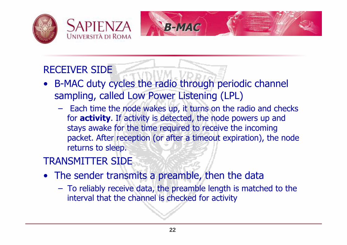
RECEIVER SIDE • B-MAC duty cycles the radio through periodic channel
sampling, called Low Power Listening (LPL) – Each time the node wakes up, it turns on the radio and checks
for activity. If activity is detected, the node powers up and stays awake for the time required to receive the incoming packet. After reception (or after a timeout expiration), the node returns to sleep.
TRANSMITTER SIDE • The sender transmits a preamble, then the data
– To reliably receive data, the preamble length is matched to the interval that the channel is checked for activity

23
B-MAC
Shifts most burden to the sender Challenge Check interval has to be short to ensure reasonable size
preambles

24
XMAC
Buettner,Yee,Anderson, Han “X-MAC: A short preamble
MAC protocol for duty cycled wireless sensor networks”, ACM
SenSys 2006

25
Starting point for XMAC
• A key advantage of asynchronous low power listening protocols such as BMAC is that sender and receiver can be completely decoupled in their duty cycles – no need for synchronization
• BMAC long preamble in low power listening however leads to performance degradation – the receiver has to wait for the full period until the preamble is finished
before the data/ack exchange can begin, even if the receiver has woken up at the start of the preamble ü increase in latency and energy consumption
– overhearing problem ü receivers who are not in the target of the sender also wake up during the
long premable and have to stay on until the end of it to discover they are not the intended destination
– Increase in energy consumption!
– latency degradation ü per hop latency lower bounded by preamble length

26
XMAC
• Ideas – embed address info of the intended destination in the preamble
ü to avoid overhearing
– use a strobed preamble : the preamble is a series of short preambles. Pauses between the short preambles allow the destination to send a fast ACK when up ü reception of an early ACK makes the sender stop sending short
preambles – the preamble is automatically set to the right size

27
XMAC
• Ideas – embed address info of the intended destination in the preamble
ü to avoid overhearing
– use a strobed preamble : the preamble is a series of short preambles. Pauses between the short preambles allow the destination to send a fast ACK when up ü reception of an early ACK makes the sender stop sending short
preambles – the preamble is automatically set to the right size

X-MAC Perf. Evaluation
• star topology, 9 sending nodes, each transmitting on average one packet per second, 500ms preamble
28

IoT Standardization
ü IEEE 802.15.4, first low-power radio standard (2003) ü ZigBee alliance: proprietary solutions for ad hoc control
network (recently opened up to some ideas of 6loWPAN) ü IPSO (IP Smart Objects alliance) founded in 2008 to
promote use of IP protocols by smart objects and promote IoT
ü IETF 6loWPAN: enable effective use of IPv6 on low power low rate simple embedded devices (2005)ß initiated by the initiative also of a group of european industry and research organization, some preliminary contributions in the EC SENSEI project
ü IETF Routing over low power and Lossy Networks (ROLL), 2008
ü ISA 100 industrial automation standard (2008)

6LoWPAN
LOW POWER WIRELESS AREA NETWORKS
(LOWPAN)
ü STUB IPV6 NETWORK
ü NODES SHARE IPV6 PREFIX
ü CONNECTED THROUGH THE INTERNET VIA A
ROUTER OR OPERATING IN AD HOC MODE

6LoWPAN LOW POWER WIRELESS AREA
NETWORKS (LOWPAN)
ü STUB IPV6 NETWORK
ü NODES SHARE IPV6 PREFIX
ü CONNECTED THROUGH THE INTERNET VIA A ROUTER OR OPERATING IN AD HOC MODE
Adaptation layer
Control messages
Neighbor discovery
All the solutions we have described are able to operate
in IEEE 802.15.4 compliant networks

IEEE 802.15.4
32
http://newyork.diet.uniroma1.it/Papers/C80-DeNardis_al-WPNC07.pdf

IEEE 802.15.4
• ISM 2.4Ghz (16 channels), 868MHz (1 channel)
• 20Kbps (868Mhz)-250Kbps (2.4Ghz) • Packet structure:

IEEE 802.15.4
• ISM 2.4Ghz (16 channels), 868MHz (1 channel)
• 20Kbps (868Mhz)-250Kbps (2.4Ghz) • Packet structure:

IEEE 802.15.4
• ISM 2.4Ghz (16 channels), 868MHz (1 channel)
• 20Kbps (868Mhz)-250Kbps (2.4Ghz) • Packet structure:

IEEE 802.15.4
• Very low power – low power transmitter/receiver – nodes can duty cycle
• Topologies:

IEEE 802.15.4
• Very low power operation – low power transmitter/receiver – nodes can duty cycle
• Topologies:
– PAN coordinator: Net ID assignment; Frequency selection; handling request to join; packet relaying
– Co-ordinator: handling request to join; packet relaying
Star
Tree Mesh

IEEE 802.15.4 How a network is started
• PAN coordinator election • PAN coordinator assigns itself a short 16 bit address (not
IEEE 64 bit addresses) • Selects the frequency • Nodes entering the network perform active scan; discover
coordinator • Send an association request, which is ACK-ed • PAN coordinator may assign a 16bit address to the joining
node

IEEE 802.15.4 MAC
ü CSMA/CA Based in Beaconless Mode
ü In Beacon Mode:

IEEE 802.15.4 MAC
ü CSMA/CA Based in Beaconless Mode
ü In Beacon Mode: IEEE 802.15.4e envisions
Other types of MAC
Beaconless mode
• CSMA/CA • If a sender has a packet to transmit it picks a random
backoff delay then it listens to the channel (CCA) • If free then it sends data which is acked • If busy it retries after waiting for an increased backoff
interval
41
All MAC protocols for sensing systems we have seen operate on
IEEE 802.15.4 compliant networks operating in beaconless mode

†Department of Computer Science – University of Rome “Sapienza” – Italy
Standard-like routing Protocols for WSNs
Internet of Things (ex Reti Avanzate), a.a. 2015/2016
Un. of Rome “La Sapienza” Chiara Petrioli†

Collec&on Tree Protocol
Omprakash Gnawali (Stanford University) with
Rodrigo Fonseca (Brown University) Kyle Jamieson (University College London) David Moss (People Power Company)
Philip Levis (Stanford University) Slides parFally taken from the presentaFon given by the authors at
ACM SenSys November 4, 2009

44
Collec&on
• Anycast route to the sink(s) – Used to collect data from the network to a small
number of sinks (roots, base staFons) – Each node selects one of its neighbors nodes as its
parent ü Parents handle packets received from the children and further forward them towards the sink
• A distance vector protocol – Metric for selecFng next hop:
ü Distance in hops from the sink ü Quality of the local communicaFon link
sink

45
Desirable proper&es for collec&on tree protocol
• Be able to esFmate and account for 1-‐hop link quality
• Mechanism to detect and repair rouFng loops • Detect and suppress duplicate packets
sink

Common Architecture
46
RouFng Engine
Forwarding Engine Link EsFmator
Link Layer
ApplicaFon
Control Plane Data Plane
Fwd
Table
Sending and receiving beacons
for route construction and maintenance
Creating and updating the routing table
Perform forwarding
Detect and Repair Loops, filter duplicate packets

Parent selec&on metric
• ETX = Expected Number of Transmissions to reach the sink • Computed based on performance experienced in the recent
past by beacon and data packets for the local 1-‐hop ETXloc
• ETXmhp via a given neighbor computed as the sum of the ETXloc
and of the esFmated ETXmhp at that neighbor
47
Parent selected only among uncongested nodes

Parent selec&on metric
• ETX = Expected Number of Transmissions to reach the sink • Computed based on performance experienced in the recent
past by beacon and data packets for the local 1-‐hop ETXloc
• ETXmhp via a given neighbor computed as the sum of the ETXloc and of the esFmated ETXmhp
at that neighbor
48
Parent selected only among uncongested nodes

49
Rou&ng Loops
– Cost does not decrease
D A
B
8.1
4.6
6.3
3.2
5.8
X C

Rou&ng Consistency
• Next hop should be closer to the desFnaFon • Maintain this consistency criteria on a path
• Inconsistency due to stale state
50
ni ni+1 nk

51
Detec&ng Rou&ng Loops
• Datapath validaFon – Cost in the packet – Receiver checks
• Inconsistency – Larger cost than on the packet
• On Inconsistency – Don’t drop the packets – Signal the control plane
D A
B
C 8.1
4.6
6.3
3.2
5.8
X
4.6
6.3
8.1
5.8
4.6 < 6.3?
3.2 < 4.6?
5.8 < 8.1?
4.6<5.8?
4.6
8.1 < 4.6?

52
Control Traffic Timing
• Extend Trickle to Fme rouFng beacons • Reset the interval
ü ETX(receiver) >= ETX(sender) ü Significant decrease in gradient ü “Pull” bit
Increasing interval Reset interval
TX
Control propagaFon rate – Start with a small interval – Double the interval up to some max – Reset to the small interval when inconsistency idenFfied

53
Adap&ve Beacon Timing
Infrequent beacons in the long run
~ 8 min
Tutornet

Adap&ve vs Periodic Beacons
54
Time (mins)
Total beacons / nod
e
Less overhead compared to 30s-‐periodic
1.87 beacon/s
0.65 beacon/s
Tutornet

Node Discovery
55
Time (mins)
Total B
eacons
A new node introduced
Efficient and agile at the same Pme
Path established in < 1s
Tutornet

Experiments
• 12 testbeds • 20-‐310 nodes • 7 hardware
plajorms • 4 radio
technologies • 6 link layers
56
VariaFons in hardware, solware, RF environment, and topology

Evalua&on Goals
• Reliable? – Packets delivered to the sink
• Efficient? – TX required per packet delivery
• Robust? – Performance with disrupFon
57

CTP Noe Trees
58
Kansei Twist
Mirage

Reliable, Efficient, and Robust
Testbed Delivery RaPo Wymanpark 0.9999 Vinelab 0.9999 Tutornet 0.9999 NetEye 0.9999 Kansei 0.9998 Mirage-‐MicaZ 0.9998 Quanto 0.9995 Blaze 0.9990 Twist-‐Tmote 0.9929 Mirage-‐Mica2dot 0.9895 Twist-‐eyesIFXv2 0.9836 Motelab 0.9607
59
High end-‐to-‐end delivery raPo (but not on all the testbeds!)
Retransmit
False ack

60
Reliable, Efficient, and Robust
High delivery raPo across Pme (short experiments can be misleading!)
Tutornet
0.98
5 10 15 20 25 30 35
Delivery cost / pkt
Time (hrs)

Reliable, Efficient, and Robust
61
Low data and control cost
Tutornet CTP Noe

Reliable, Efficient, and Robust
62
0
0.2
0.4
0.6
0.8
1
CSMA BoX-‐1s LPP-‐500msLink Layer
Duty-‐cycle
Low duty-‐cycle with low-‐power MACs
0.028 0.066
Motelab, 1pkt/5min

Reliable, Efficient, and Robust
63
Time (mins)
Delivery Ra
Po
10 out of 56 nodes removed at t=60 mins
No disrupPon in packet delivery
Tutornet

Nodes reboot every 5 mins
64
Reliable, Efficient, and Robust
Delivery RaFo > 0.99
RouFng Beacons
High delivery raPo despite serious network-‐wide disrupPon (most loss due to reboot while buffering packet)
~ 5 min
Tutornet

Routing in IoT
• Desirable features – Energy aware, small factor, lightweight solutions, low overhead – Should scale to thousands of smart objects – Long lasting systems (years or decades) – Auto-configuration, self-managing – Robust even in presence of varying link quality and unreliable
links

ROLL--Routing Over Low power and Lossy
• “Ripple” routing protocol RPL-- Proactive distance vector routing; – specifies how to build a destination oriented acyclic graph (DODAG)
• Multi-hop support • Flexible metric
– <Find paths with the best ETX and avoid non encrypted links> or <Find the best path in terms of latency while avoiding battery operated nodes>.
– Administrator may decide to have multiple routing topologies active at the same time to carry traffic with different requirements
– dynamic metrics (link quality, CPU overload, battery levels, all fast change over time…)
• Focus on energy constrained, secure solutions • Routing supported across multiple types of link layers

RPL– DODAG formation
• RPL specifies how to build a destination oriented acyclic graph (DODAG) • Root (ER) sends a DIO (DODAG Information Object) message • Neighbors of the root will listen to the DIO and decide whether to join DODAG. They can decide to become a router and re-forward the DIO. – Each of their neighbors, upon receiving the DIO, selects its parent
(according to a suitable metric) and –if it decides to become a router- reforwards the DIO.
This rippling effect builds the graph edges out from the root to the leaf nodes where the process terminates.

RPL -- How to multicast messages
• Destination Advertisement Object (DAO) • As a node joins the graph it sends a DAO to its parent
(can also be solicited) • DAO messages are forwarded till the root • Prefix reachability info exchange also enables peer to
peer communication – up along the tree till the common ancestor, then down till the
intended destination

RPL –trickle timers
• How often are DIO messages sent? – Dynamically selected (trickle timer) based on how stable the
system is – If the system stabilizes it is seldom sent – Whenever an inconsistency is detected (such as loop or changes
in the DODAG) then the timer is reset to small values

Adaptation layer: 6LoWPAN
• Addressing: not routable local addresses. Smart objects are permanently identified by EUI-64 identifiers (8 bytes) – short 16 bit local address is assigned during network bootstrapping to
reduce overhead
• IPv6 address can be (and must be in 6LoWPAN) obtained by concatenating a 64bit network address with the EUI-64

6LoWPAN Routing Updated by the
Selected routing
protocol
Specifies type and subtype of the header (i.e., which is the
meaning of the following information, how many bits
Are allocated to each field)

6LowPAN
73

Fragmentation
• Used when transmitting L2-L3 PDU larger than 128 bytes • Fragmentation/reassembly performed at the link level.
Fragmentation header:
• Compression again as key apect for header design.
Together with source/destination used to
Identify the original packet
Identifies order of fragment within the sequence
of fragments of the same packet

6LowPAN
75

6LoWPAN Routing Updated by the
Selected routing
protocol
Specifies type and subtype of the header (i.e., which is the
meaning of the following information, how many bits
Are allocated to each field)
We need info on very first node
(V—source node), e.g., for reassembly,
and on final destination (F) for routing.
Such information are always provided
In the mesh header (which is the first
Header in multi-hop networks)

6LowPAN
77

6LoWPAN Routing Updated by the
Selected routing
protocol
Specifies type and subtype of the header (i.e., which is the
meaning of the following information, how many bits
Are allocated to each field)
V and F bits say whether a 64 or 16 bit
Address will follow

Header Compression
• Limited Packet size • Transmitting 128bits addresses + information needed for
security purposes can lead to very high overhead • Solution: header compression
– Stateless header compression ü HC1: compresses IPv6 headers ü HC2 compresses UDP headers
HC1 compression
Identifies that an HC2 header follows

Header Compression
• Limited Packet size • Transmitting 128bits addresses + information needed for security purposes can lead to very high overhead • Solution: header compression
– Stateless header compression
IPv6 packet header
Always 6 not
transmitted in HC1
Often 0. C=1 means their
values are zero
Can be inferred by other
Headers--Not transmitted
Some likely values
(UDP,TCP,ICMP)
expressed by
The two bit NH. If
NH !=0 can be
skipped Used to avoid transmitting
First 64 bits of the address

Header Compression
• Limited Packet size • Transmitting 128bits addresses + information needed for
security purposes can lead to very high overhead • Solution: header compression
– Stateless header compression ü HC1: compresses IPv6 headers ü HC2 compresses UDP headers
Source/destination
port field compression
How? favoring port selection
among a subset of possible
ports
Indicates length size can be inferred and is thus not included

Bootstrapping an IoT network
• Edge Router broadcasts general information • Association procedure for new nodes (they select the
router to affiliate to based on ER metric; Node registration/confirmation)
• Procedure to assign local addresses, identify and solve duplicate addresses.
Broadcast packet

Bootstrapping an IoT network
• Edge Router broadcasts general information • Association procedure for new nodes • Procedure to assign local addresses, identify and solve
duplicate addresses.

Bootstrapping an IoT network
• Edge Router broadcasts general information • Association procedure for new nodes • Procedure to assign local addresses, identify and solve
duplicate addresses.

†Department of Computer Science – University of Rome “Sapienza” – Italy
Protocols for EH-WSNs
Internet of Things, a.a. 2015/2016 Un. of Rome “La Sapienza”
Chiara Petrioli†

EH-WNS
86
• Pose the basis for very long lasting operation
• Energy Neutral protocols have been proposed
for several applications
• Changes also what a WSN can do

Why energy predic&ons?
• Energy predicFons to miFgate uncertain energy availability • Plan energy usage in advance: proacPve vs reacFve energy allocaFon • Exploit available energy at best:
I. Minimizing the likelihood of running out of energy and missing high priority tasks
II. Minimizing the waste of energy (energy buffers are limited in size and Fme)
III. Enable operaFons which were not considered feasible

Pro-‐Energy in a nutshell
• Keep track of energy profiles observed during D typical days • Store traces representaFve of different weather condiFons (sunny, windy, ...) • Predict future energy intake by looking at the most similar stored profile
Current observation Stored profile

Pro-‐Energy in a nutshell

90
Medium term energy
prediction
estimation
Medium Term Energy Predic&ons

Pro-‐Energy accuracy
Solar Wind
Solar: Pro-‐Energy performs up to 75% berer than EWMA and 60% berer than WCMA
Wind: Pro-‐Energy performs up to 55% berer than EWMA and 10% berer than WCMA

Rome underground testbed
Why air-flow energy harvesting?
• SHM sensors are power-hungry
• required lifetime of decades or more
• battery-powered WSNs last only a few years

In-field air-flow data collection
220 meter of instrumented tunnel 6 energy-harvesting nodes 33 days of data collection

Feasibility study
Collect hundreds of humidity and temperature samples
Up to 133 mJ harvested per train passage
Transmit/receive tens of KB
Up to 36 strain measurements per day
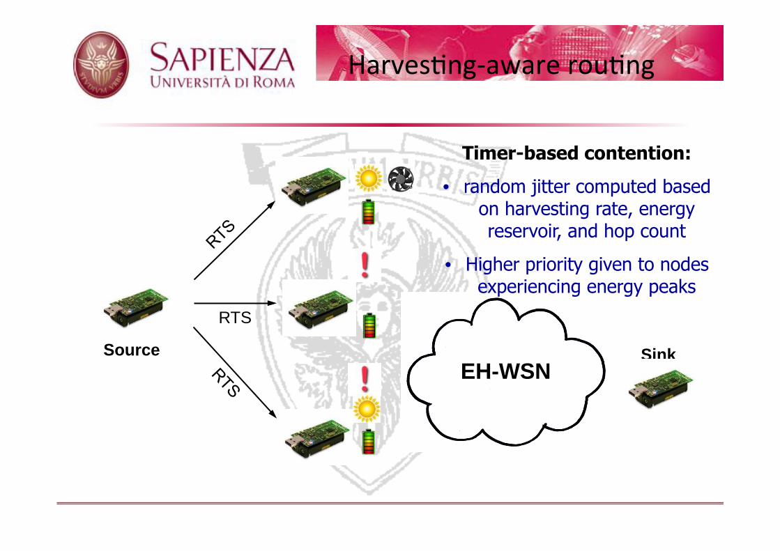
HarvesFng-‐aware rouFng
EH-WSN
RTS
Sink Source
Timer-based contention:
• random jitter computed based on harvesting rate, energy reservoir, and hop count
• Higher priority given to nodes experiencing energy peaks

HarvesFng-‐aware rouFng
EH-WSN Sink Source
Timer-based contention:
• random jitter computed based on harvesting rate, energy reservoir, and hop count
• Higher priority given to nodes experiencing energy peaks

HarvesFng-‐aware rouFng
EH-WSN Sink Source
Timer-based contention:
• random jitter computed based on harvesting rate, energy reservoir, and hop count
• Higher priority given to nodes experiencing energy peaks

HarvesFng-‐aware rouFng
EH-WSN Sink Source
Timer-based contention:
• random jitter computed based on harvesting rate, energy reservoir, and hop count
• Higher priority given to nodes experiencing energy peaks

HarvesFng-‐aware rouFng
EH-WSN Sink Source
Timer-based contention:
• random jitter computed based on harvesting rate, energy reservoir, and hop count
• Higher priority given to nodes experiencing energy peaks

GreenCastalia: Mo&va&on
¢ GreenCastalia features � Support for multi-source harvesting � Support for multi-storage devices � Support for energy predictions � Easily customizable � Based on Castalia / OMNET++
Sensor node
TraceEnergySource module: allows to feed the simulator with timestamped power traces collected through real-
life deployments, or with energy availability traces obtained by data
repositories or meteorological stations

HarvesFng-‐aware rouFng: Results
Simulation settings
• 120x120 meters field (7x7 grid deployment)
• Nodes with heterogeneus energy harvesting capabilities: • solar, wind both, none
11am 5pm with shadow zone
Self-‐adapPve behaviour: nodes experiencing energy peaks are selected with higher priority as next hop relays
8pm

Task allocation
• Sensing tasks (missions) arrive in the network dynamically over time at different locations
• Multiple missions active at the same time, competing for the sensing resources of the network
Decide which sensor(s) should be assigned to each mission
Sensing task C
Sensing task B
Sensing task A

QoS-aware operations
• Missions have different priority (profit) and require different amount of resources (demand) Sensing task
A
Sensing task C
Sensing task B
• Assigments are not all equal.. • Nodes contribute to different missions
with different utility (quality of information)
• Achieved profit depends on allocated demand
0
1
0
Minimumsatisfaction
threshold
Fractionof profit
Fraction of demand 1
GOAL
Maximize the profit obtained by the network for missions execuFon within a given target lifePme
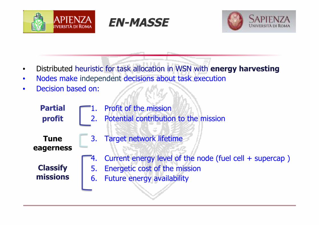
• Distributed heuristic for task allocation in WSN with energy harvesting • Nodes make independent decisions about task execution • Decision based on:
1. Profit of the mission 2. Potential contribution to the mission
3. Target network lifetime
4. Current energy level of the node (fuel cell + supercap ) 5. Energetic cost of the mission 6. Future energy availability
Partial profit
Tune
eagerness
Classify missions
EN-MASSE

A new mission arrives check energy requirements and energy availability
Fuel cell/battery required not enough energy in the supercapacitor to execute the mission; use energy from the fuel-cell
Capacitor sustainable mission energy cost sustained by supercapacitor
Recoverable mission energy cost sustained by supercapacitor AND energy cost recovered through harvesting before the next mission arrives
Free mission energy cost expected to be fully sustained by energy harvesting
Mission classification
More willing to accept
REQUIRE ENERGY PREDICTIONS

Mission selection rule capacitor sustainable and recoverable
• Expected partial profit of a mission
P maximum achievable profit: E[u],E[d],E[p] expected utility, demand and profit of a given mission • Partial profit achievable by a node participating to a
mission
w weight which depends on mission classification. Bid if p*>=expected partial profit
107
Always for free missions

Task-‐Alloca&on EN-‐MASSE-‐In summary
Higher priority to less-impacting missions 1. Free: fully sustained by harvesting 2. Recoverable: sustained by supercapacitor
and recovered before next mission 3. Capacitor-sustainable: sustained by
supercapacitor 4. Battery-required: sustained by battery
A decentralized harvesting-aware heuristic
Key features:
• Uses short and long term energy predictions for pro-active energy allocation
• Takes into account missions arrival statistics to make sustainable allocation decisions
• Considers the impact of executing a mission on node energy

Real-‐life energy traces Photovoltaic cells Wind micro-‐turbines
0
1000
2000
3000
4000
5000
6000
7000
15/0500:00
15/0506:00
15/0512:00
15/0518:00
16/0500:00
16/0506:00
16/0512:00
16/0518:00
17/0500:00
17/0506:00
17/0512:00
17/0518:00
18/0500:00
Turb
ine
Volt
age
[mV
]
Node 3 - Section 156 - 218 m
Modeling real harvesting systems
Non-ideal supercapacitors 1. Finite size 2. Charging\discharging
efficiency < 1 3. Leakage\self-discharge
0100200300400
2
4
6
8
Remaining Energy [J]
LeakagePower[mW]
22F10
33F50F100F

Performance evalua&on
Profit: up to 60% higher than SoA
In-field testbed validation
Gap between simulations and testbed: less than 3% of maximum profit
Stable profit: 70-80% of maximum