mach 130f / 130 - frank's hospital workshop_130f_-_user_ma… · dr. mach mach 130f/130...
TRANSCRIPT
MACH 130F/130 Ceiling, Wall, Stand model Dr. Mach
Lamps and Engineering
Directions for use
MACH 130F/130 MACH 130F 22,8V UL UNIFLEX R96 120V UL
Mach 130F;130 / Uniflex R96 120V UL stand-lamp - one-handed height adjustment Mach 130F;130 stand-lamp – new type stand Mach 130F;130F 22,8V UL;130 / Uniflex R96 120V UL wall lamp Mach 130F;130F 22,8V UL;130 / Uniflex R96 120V UL single ceiling-lamp Mach 130F;130F 22,8V UL;130 / Uniflex R96 120V UL combined ceiling-lamp
Dr. Mach GmbH u. Co., Flossmannstrasse 28, D-85560 Ebersberg Tel.: +49 (0)8092 2093 0, Fax +49 (0)8092 2093 50
Internet: www.dr-mach.com, E-mail: [email protected]
59100001 Edition 12 07.02.2005 / Bak Page 1/28
MACH 130F/130 Ceiling, Wall, Stand model Dr. Mach
Lamps and Engineering
List of contents
1. Safety instructions ............................................................................................... Page 3 2. Operating the lamp Mach 130/Uniflex R96 120V UL .......................................... Page 4
2.1 ON/OFF switch, light intensity control........................................................... Page 4 2.2 Positioning .................................................................................................... Page 5 2.3 Light field adjustment (focusing) ................................................................... Page 5
3. Cleaning .............................................................................................................. Page 6
3.1 Sterilizable handle ........................................................................................ Page 6 3.2 Lamp head, protective disk........................................................................... Page 8
4.Maintenance......................................................................................................... Page 9
4.1 Adjustments at the ceiling/ wall attachment.................................................. Page 9 4.2 Adjustments at the stand model ................................................................... Page 10 4.3 Adjustments at the lamp head ...................................................................... Page 11 4.4 Changing of spare parts ............................................................................... Page 12
4.4.1 Changing the halogen bulbs ................................................................. Page 12 4.4.2 Changing the fuses (230V; 120V)......................................................... Page 13 4.4.3 Changing the ON/OFF switch (potentiometer) (before 10.2002) .......... Page 14 4.4.4 Changing the ON/OFF switch (potentiometer) (after 10.2002) ............. Page 15 4.4.5 Changing the filter disk ......................................................................... Page 16 4.4.6 Changing the protective disk................................................................. Page 17 4.4.7 Conversion to sterilizable handle .......................................................... Page 18
5. Data..................................................................................................................... Page 19
5.1 Technical data .............................................................................................. Page 19 5.2 Wiring............................................................................................................ Page 20 5.3 Environmental conditions.............................................................................. Page 21
6. Characteristics..................................................................................................... Page 21
6.1 Specification of bulb...................................................................................... Page 22 6.2 Specification of fuse...................................................................................... Page 22 6.3 CE-mark........................................................................................................ Page 22
7. Disposal............................................................................................................... Page 22 8. Spare parts.......................................................................................................... Page 23
8.1 Mach 130F 230V ceiling/wall/stand model - short arm................................ Page 23 8.2 Mach 130 230V ceiling/wall/stand model - short arm .................................. Page 24 8.3 Mach 130F/130 120V ceiling/wall/stand model - short arm ......................... Page 25 8.4 Uniflex R96 UL 120V* ceiling/wall/stand model - short arm ........................ Page 25 8.5 Mach 130F 22,8V ceiling/wall model ........................................................... Page 26 8.6 Mach 130F UL 22,8V ceiling/wall model* ................................................... Page 26 8.7 Short arm (stand model) ............................................................................... Page 26 8.8 SWING (stand model)................................................................................... Page 26 8.9 Spare parts list.............................................................................................. Page 27
* For spare parts of the ceiling and wall attachment see separate instructions for the UL- recog-
nised products.
59100001 Edition 12 07.02.2005 / Bak Page 2/28
MACH 130F/130 Ceiling, Wall, Stand model Dr. Mach
Lamps and Engineering
1. Safety instructions
Please pay attention to the directions for use when handling the lamp.
Attention:
This device is not suitable for use in hazardous locations. The lamp is classified as a Group 1 device according to the Regulations for EEMP.
Repairs to the lamp and special installation work on the reflector or plug-in socket should only be carried out by ourselves or a company expressly authorised by ourselves. The manufacturer is only responsible for the safety of the lamp if repairs and alterations have been carried out by themselves or a company who can guarantee that the safety regulations have been observed. The manufacturer is not liable for personal or material damages if the lamp is misappro-priately or incorrectly operated or misused.
Make sure that the lamp is in perfect working order before every use.
The lamps Mach 130F/130F 22,8V UL and Uniflex R96 120V UL may not be used without the dielectric filter disk.
The dielectric filter disk between reflector and protective disk prevents a damaging heating of the illuminated area.
The lamps Mach 130 may not be used without the conversion filter. The lamp body may only be dismantled from swivel arm the (in reverse order to its assem-bly) after the arm has been secured since the arm is under spring tension.
Installation of Mach 130/130F with electronic transformer 230V
Installing the lamp connect the phase to the ON/OFF switch. The voltage of the neutral line has to be less than low voltage.
59100001 Edition 12 07.02.2005 / Bak Page 3/28
MACH 130F/130 Ceiling, Wall, Stand model Dr. Mach
Lamps and Engineering
2. Operating the lamp Mach 130/Uniflex R96 120V UL
Features of of Mach 130 / Uniflex lamps: • Mach 130F with focusable light field size and
integrated dielectric filter disk The reflector is adapted to the dielectric filter disk.
• Mach 130 with fix-focus and integrated con-version filter The reflector is adapted to the conversion filter.
• Mach 130F 22,8V UL with focusable light field size and integrated dielectric filter disk. The reflector is adapted to the dielectric filter disk.
• Uniflex R96 120V UL with focusable light field size and integrated dielectric filter disk. The reflector is adapted to the dielectric filter disk.
The lamp-types mentioned above are available as: • Mach 130F/130 22,8V / external transformer • Mach 130F/130 120V / integrated toroid trans-
former • Mach 130F/130 230V / integrated electronic
transformer and light intensity control • Uniflex R96 UL 120V / integrated toroid trans-
former • Mach 130F UL 22,8V / external transformer 2.1 ON/OFF switch,
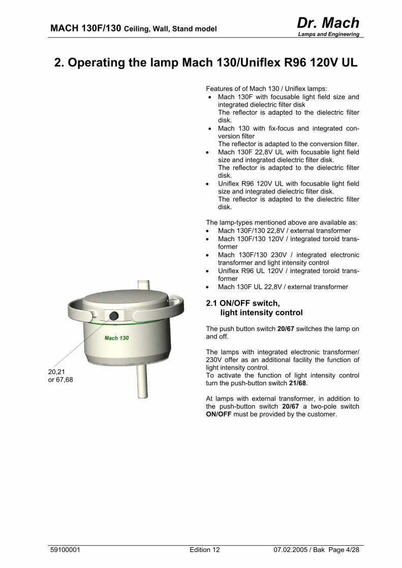
light intensity control The push button switch 20/67 switches the lamp on and off. The lamps with integrated electronic transformer/ 230V offer as an additional facility the function of light intensity control. To activate the function of light intensity control turn the push-button switch 21/68. At lamps with external transformer, in addition to the push-button switch 20/67 a two-pole switch ON/OFF must be provided by the customer.
20,21 or 67,68
59100001 Edition 12 07.02.2005 / Bak Page 4/28
MACH 130F/130 Ceiling, Wall, Stand model Dr. Mach
Lamps and Engineering
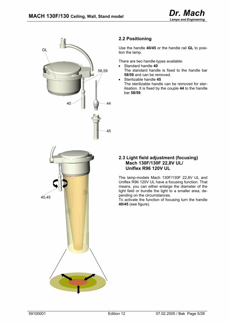
2.2 Positioning Use the handle 40/45 or the handle rail GL to posi-tion the lamp. There are two handle-types available: • Standard handle 40
The standard handle is fixed to the handle bar 58/59 and can be removed.
• Sterilizable handle 45 The sterilizable handle can be removed for ster-ilisation. It is fixed by the couple 44 to the handle bar 58/59.
2.3 Light field adjustment (focusing)
Mach 130F/130F 22,8V UL/ Uniflex R96 120V UL
The lamp-models Mach 130F/130F 22,8V UL and Uniflex R96 120V UL have a focusing function. That means, you can either enlarge the diameter of the light field or bundle the light to a smaller area, de-pending on the circumstances. To activate the function of focusing turn the handle 40/45 (see figure).
GL
58,59
40 44
45
40,45
59100001 Edition 12 07.02.2005 / Bak Page 5/28
MACH 130F/130 Ceiling, Wall, Stand model Dr. Mach
Lamps and Engineering
3. Cleaning
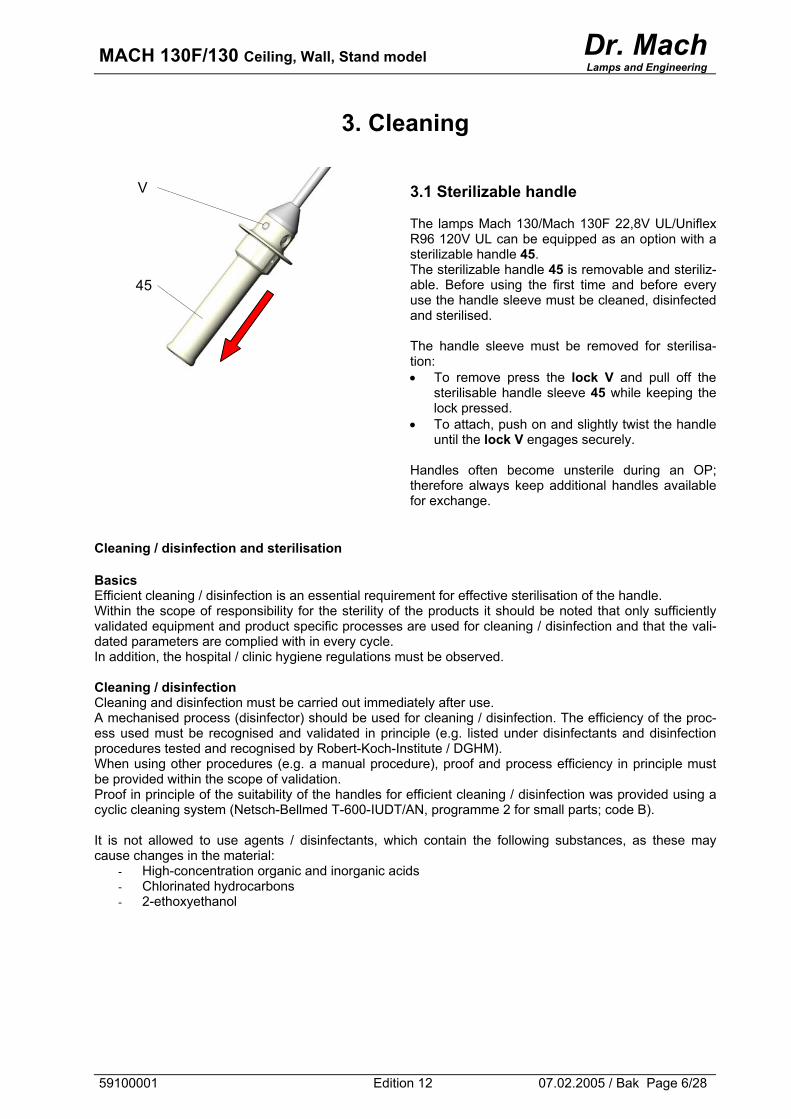
3.1 Sterilizable handle The lamps Mach 130/Mach 130F 22,8V UL/Uniflex R96 120V UL can be equipped as an option with a sterilizable handle 45. The sterilizable handle 45 is removable and steriliz-able. Before using the first time and before every use the handle sleeve must be cleaned, disinfected and sterilised. The handle sleeve must be removed for sterilisa-tion: • To remove press the lock V and pull off the
sterilisable handle sleeve 45 while keeping the lock pressed.
• To attach, push on and slightly twist the handle until the lock V engages securely.
Handles often become unsterile during an OP; therefore always keep additional handles available for exchange.
45
V
Cleaning / disinfection and sterilisation Basics Efficient cleaning / disinfection is an essential requirement for effective sterilisation of the handle. Within the scope of responsibility for the sterility of the products it should be noted that only sufficiently validated equipment and product specific processes are used for cleaning / disinfection and that the vali-dated parameters are complied with in every cycle. In addition, the hospital / clinic hygiene regulations must be observed. Cleaning / disinfection Cleaning and disinfection must be carried out immediately after use. A mechanised process (disinfector) should be used for cleaning / disinfection. The efficiency of the proc-ess used must be recognised and validated in principle (e.g. listed under disinfectants and disinfection procedures tested and recognised by Robert-Koch-Institute / DGHM). When using other procedures (e.g. a manual procedure), proof and process efficiency in principle must be provided within the scope of validation. Proof in principle of the suitability of the handles for efficient cleaning / disinfection was provided using a cyclic cleaning system (Netsch-Bellmed T-600-IUDT/AN, programme 2 for small parts; code B). It is not allowed to use agents / disinfectants, which contain the following substances, as these may cause changes in the material:
- High-concentration organic and inorganic acids - Chlorinated hydrocarbons - 2-ethoxyethanol
59100001 Edition 12 07.02.2005 / Bak Page 6/28
MACH 130F/130 Ceiling, Wall, Stand model Dr. Mach
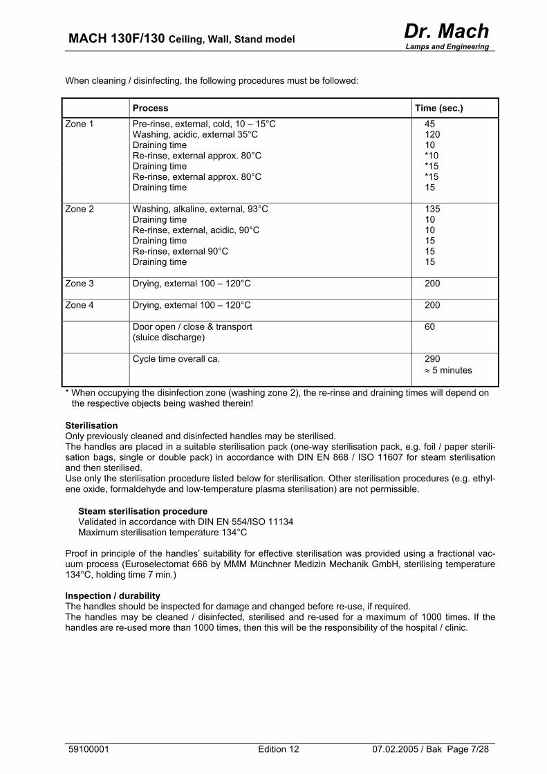
Lamps and Engineering When cleaning / disinfecting, the following procedures must be followed: Process Time (sec.) Zone 1 Pre-rinse, external, cold, 10 – 15°C 45 Washing, acidic, external 35°C 120 Draining time 10 Re-rinse, external approx. 80°C *10 Draining time *15 Re-rinse, external approx. 80°C *15 Draining time 15 Zone 2 Washing, alkaline, external, 93°C 135 Draining time 10 Re-rinse, external, acidic, 90°C 10 Draining time 15 Re-rinse, external 90°C 15 Draining time 15 Zone 3 Drying, external 100 – 120°C 200 Zone 4 Drying, external 100 – 120°C 200 Door open / close & transport 60 (sluice discharge) Cycle time overall ca. 290 ≈ 5 minutes * When occupying the disinfection zone (washing zone 2), the re-rinse and draining times will depend on
the respective objects being washed therein! Sterilisation Only previously cleaned and disinfected handles may be sterilised. The handles are placed in a suitable sterilisation pack (one-way sterilisation pack, e.g. foil / paper sterili-sation bags, single or double pack) in accordance with DIN EN 868 / ISO 11607 for steam sterilisation and then sterilised. Use only the sterilisation procedure listed below for sterilisation. Other sterilisation procedures (e.g. ethyl-ene oxide, formaldehyde and low-temperature plasma sterilisation) are not permissible.
Steam sterilisation procedure Validated in accordance with DIN EN 554/ISO 11134 Maximum sterilisation temperature 134°C
Proof in principle of the handles’ suitability for effective sterilisation was provided using a fractional vac-uum process (Euroselectomat 666 by MMM Münchner Medizin Mechanik GmbH, sterilising temperature 134°C, holding time 7 min.) Inspection / durability The handles should be inspected for damage and changed before re-use, if required. The handles may be cleaned / disinfected, sterilised and re-used for a maximum of 1000 times. If the handles are re-used more than 1000 times, then this will be the responsibility of the hospital / clinic.
59100001 Edition 12 07.02.2005 / Bak Page 7/28
MACH 130F/130 Ceiling, Wall, Stand model Dr. Mach
Lamps and Engineering
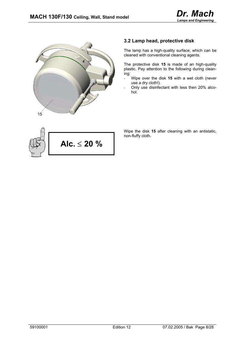
3.2 Lamp head, protective disk The lamp has a high-quality surface, which can be cleaned with conventional cleaning agents. The protective disk 15 is made of an high-quality plastic. Pay attention to the following during clean-ing: - Wipe over the disk 15 with a wet cloth (never
use a dry cloth!). - Only use disinfectant with less then 20% alco-
hol.
Wipe the disk 15 after cleaning with an antistatic, non-fluffy cloth.
15
Alc. ≤ 20 %
59100001 Edition 12 07.02.2005 / Bak Page 8/28
MACH 130F/130 Ceiling, Wall, Stand model Dr. Mach
Lamps and Engineering
4. Maintenance
The lamp has been designed and built so that regular maintenance intervals are not necessary. In order to keep the system easy running throughout its life span we recommend that the hinges be greased once a year with an acid-free grease.
4.1 Adjustments at the ceiling / wall attachment
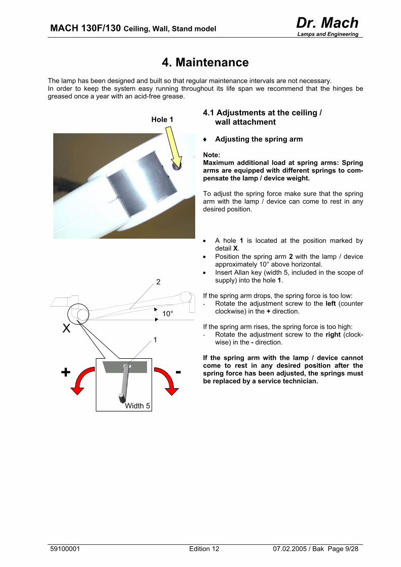
♦ Adjusting the spring arm Note: Maximum additional load at spring arms: Spring arms are equipped with different springs to com-pensate the lamp / device weight. To adjust the spring force make sure that the spring arm with the lamp / device can come to rest in any desired position. • A hole 1 is located at the position marked by
detail X. • Position the spring arm 2 with the lamp / device
approximately 10° above horizontal. • Insert Allan key (width 5, included in the scope of
supply) into the hole 1. If the spring arm drops, the spring force is too low: - Rotate the adjustment screw to the left (counter
clockwise) in the + direction. If the spring arm rises, the spring force is too high: - Rotate the adjustment screw to the right (clock-
wise) in the - direction. If the spring arm with the lamp / device cannot come to rest in any desired position after the spring force has been adjusted, the springs must be replaced by a service technician.
Hole 1
2
10°
X
Width 5
1
-+
59100001 Edition 12 07.02.2005 / Bak Page 9/28
MACH 130F/130 Ceiling, Wall, Stand model Dr. Mach
Lamps and Engineering
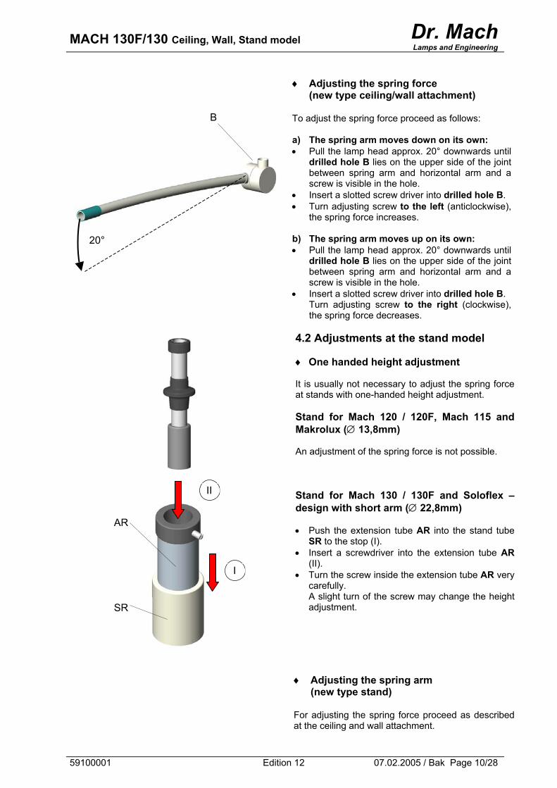
♦ Adjusting the spring force (new type ceiling/wall attachment)
To adjust the spring force proceed as follows: a) The spring arm moves down on its own: • Pull the lamp head approx. 20° downwards until
drilled hole B lies on the upper side of the joint between spring arm and horizontal arm and a screw is visible in the hole.
• Insert a slotted screw driver into drilled hole B. • Turn adjusting screw to the left (anticlockwise),
the spring force increases. b) The spring arm moves up on its own: • Pull the lamp head approx. 20° downwards until
drilled hole B lies on the upper side of the joint between spring arm and horizontal arm and a screw is visible in the hole.
• Insert a slotted screw driver into drilled hole B. Turn adjusting screw to the right (clockwise), the spring force decreases.
4.2 Adjustments at the stand model ♦ One handed height adjustment It is usually not necessary to adjust the spring force at stands with one-handed height adjustment.
Stand for Mach 120 / 120F, Mach 115 and Makrolux (∅ 13,8mm) An adjustment of the spring force is not possible.
B
20°
Stand for Mach 130 / 130F and Soloflex – design with short arm (∅ 22,8mm) • Push the extension tube AR into the stand tube
SR to the stop (I). • Insert a screwdriver into the extension tube AR
(II). • Turn the screw inside the extension tube AR very
carefully. A slight turn of the screw may change the height adjustment.
♦ Adjusting the spring arm
(new type stand) For adjusting the spring force proceed as described at the ceiling and wall attachment.
II
AR
I
SR
59100001 Edition 12 07.02.2005 / Bak Page 10/28
MACH 130F/130 Ceiling, Wall, Stand model Dr. Mach
Lamps and Engineering
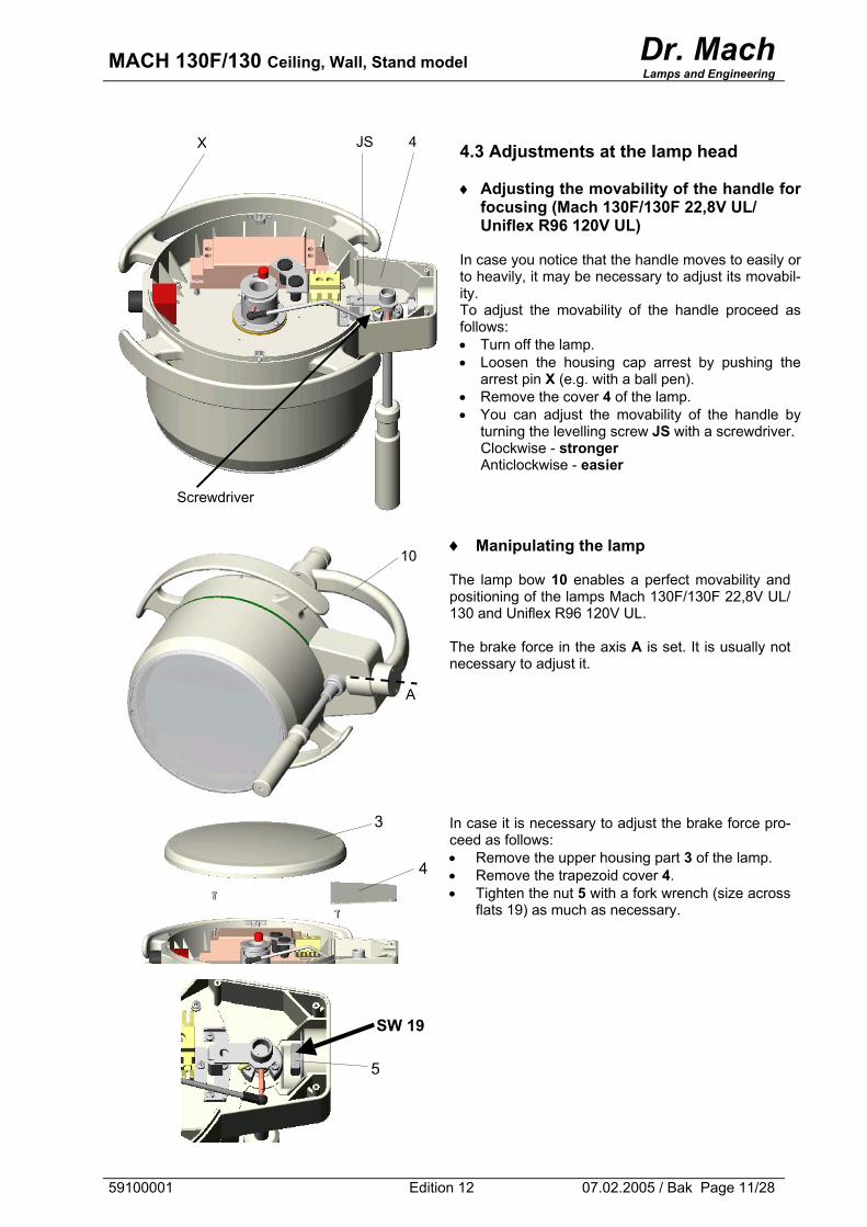
4.3 Adjustments at the lamp head ♦ Adjusting the movability of the handle for
focusing (Mach 130F/130F 22,8V UL/ Uniflex R96 120V UL)
In case you notice that the handle moves to easily or to heavily, it may be necessary to adjust its movabil-ity. To adjust the movability of the handle proceed as follows: • Turn off the lamp. • Loosen the housing cap arrest by pushing the
arrest pin X (e.g. with a ball pen). • Remove the cover 4 of the lamp. • You can adjust the movability of the handle by
turning the levelling screw JS with a screwdriver. Clockwise - stronger Anticlockwise - easier
♦ Manipulating the lamp The lamp bow 10 enables a perfect movability and positioning of the lamps Mach 130F/130F 22,8V UL/ 130 and Uniflex R96 120V UL. The brake force in the axis A is set. It is usually not necessary to adjust it.
In case it is necessary to adjust the brake force pro-ceed as follows: • Remove the upper housing part 3 of the lamp. • Remove the trapezoid cover 4. • Tighten the nut 5 with a fork wrench (size across
flats 19) as much as necessary.
4 JS X
Screwdriver
10
A
SW 19
5
4
3
59100001 Edition 12 07.02.2005 / Bak Page 11/28
MACH 130F/130 Ceiling, Wall, Stand model Dr. Mach
Lamps and Engineering
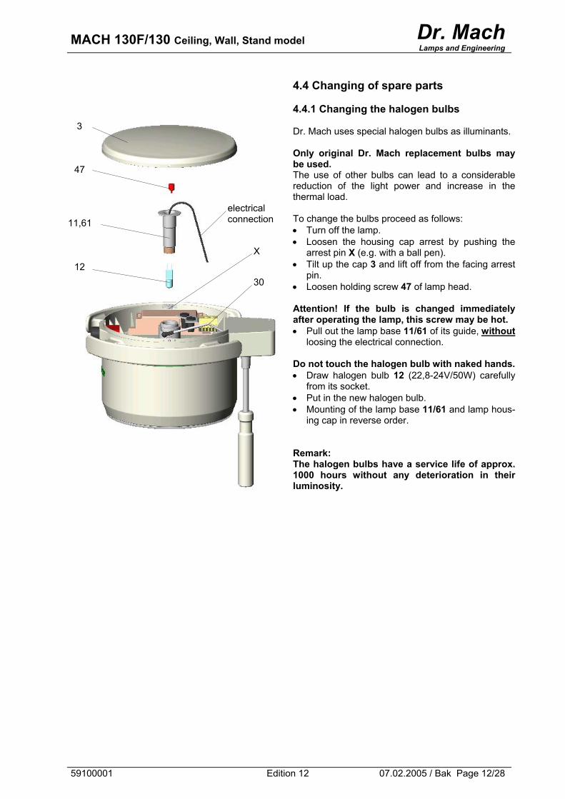
4.4 Changing of spare parts 4.4.1 Changing the halogen bulbs Dr. Mach uses special halogen bulbs as illuminants. Only original Dr. Mach replacement bulbs may be used. The use of other bulbs can lead to a considerable reduction of the light power and increase in the thermal load. To change the bulbs proceed as follows: • Turn off the lamp. • Loosen the housing cap arrest by pushing the
arrest pin X (e.g. with a ball pen). • Tilt up the cap 3 and lift off from the facing arrest
pin. • Loosen holding screw 47 of lamp head.
Attention! If the bulb is changed immediately after operating the lamp, this screw may be hot. • Pull out the lamp base 11/61 of its guide, without
loosing the electrical connection. Do not touch the halogen bulb with naked hands.• Draw halogen bulb 12 (22,8-24V/50W) carefully
from its socket. • Put in the new halogen bulb. • Mounting of the lamp base 11/61 and lamp hous-
ing cap in reverse order. Remark: The halogen bulbs have a service life of approx. 1000 hours without any deterioration in their luminosity.
30
X
electrical connection
12
11,61
47
3
59100001 Edition 12 07.02.2005 / Bak Page 12/28
MACH 130F/130 Ceiling, Wall, Stand model Dr. Mach
Lamps and Engineering
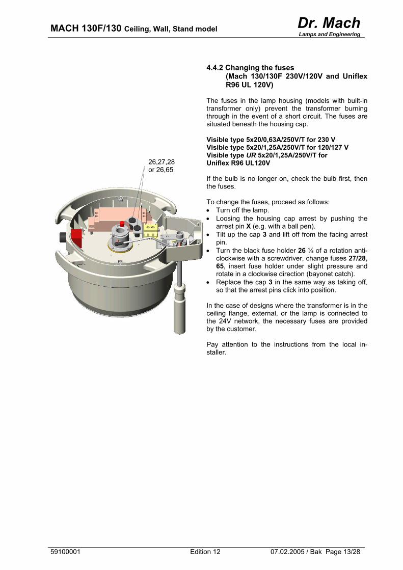
4.4.2 Changing the fuses
(Mach 130/130F 230V/120V and Uniflex R96 UL 120V)
The fuses in the lamp housing (models with built-in transformer only) prevent the transformer burning through in the event of a short circuit. The fuses are situated beneath the housing cap. Visible type 5x20/0,63A/250V/T for 230 V Visible type 5x20/1,25A/250V/T for 120/127 V Visible type UR 5x20/1,25A/250V/T for Uniflex R96 UL120V If the bulb is no longer on, check the bulb first, then the fuses. To change the fuses, proceed as follows: • Turn off the lamp. • Loosing the housing cap arrest by pushing the
arrest pin X (e.g. with a ball pen). • Tilt up the cap 3 and lift off from the facing arrest
pin. • Turn the black fuse holder 26 ¼ of a rotation anti-
clockwise with a screwdriver, change fuses 27/28, 65, insert fuse holder under slight pressure and rotate in a clockwise direction (bayonet catch).
• Replace the cap 3 in the same way as taking off, so that the arrest pins click into position.
In the case of designs where the transformer is in the ceiling flange, external, or the lamp is connected to the 24V network, the necessary fuses are provided by the customer. Pay attention to the instructions from the local in-staller.
26,27,28 or 26,65
59100001 Edition 12 07.02.2005 / Bak Page 13/28
MACH 130F/130 Ceiling, Wall, Stand model Dr. Mach
Lamps and Engineering
potentiometer
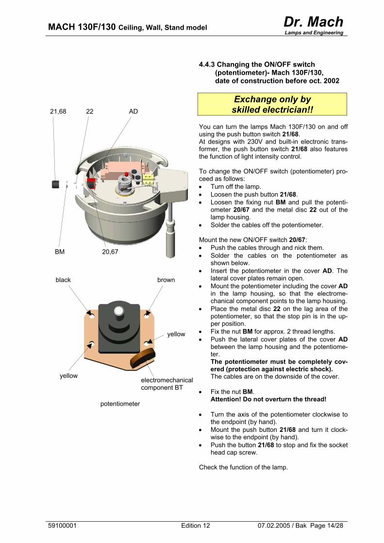
4.4.3 Changing the ON/OFF switch
(potentiometer)- Mach 130F/130, date of construction before oct. 2002
Exchange only by skilled electrician!!
You can turn the lamps Mach 130F/130 on and off using the push button switch 21/68. At designs with 230V and built-in electronic trans-former, the push button switch 21/68 also features the function of light intensity control. To change the ON/OFF switch (potentiometer) pro-ceed as follows: • Turn off the lamp. • Loosen the push button 21/68. • Loosen the fixing nut BM and pull the potenti-
ometer 20/67 and the metal disc 22 out of the lamp housing.
• Solder the cables off the potentiometer. Mount the new ON/OFF switch 20/67: • Push the cables through and nick them. • Solder the cables on the potentiometer as
shown below. • Insert the potentiometer in the cover AD. The
lateral cover plates remain open. • Mount the potentiometer including the cover AD
in the lamp housing, so that the electrome-chanical component points to the lamp housing.
• Place the metal disc 22 on the lag area of the potentiometer, so that the stop pin is in the up-per position.
• Fix the nut BM for approx. 2 thread lengths. • Push the lateral cover plates of the cover AD
between the lamp housing and the potentiome-ter. The potentiometer must be completely cov-ered (protection against electric shock). The cables are on the downside of the cover.
• Fix the nut BM. Attention! Do not overturn the thread!
• Turn the axis of the potentiometer clockwise to the endpoint (by hand).
• Mount the push button 21/68 and turn it clock-wise to the endpoint (by hand).
• Push the button 21/68 to stop and fix the socket head cap screw.
Check the function of the lamp.
21,68 22 AD
BM 20,67
black brown
yellow
yellow electromechanical component BT
59100001 Edition 12 07.02.2005 / Bak Page 14/28
MACH 130F/130 Ceiling, Wall, Stand model Dr. Mach
Lamps and Engineering
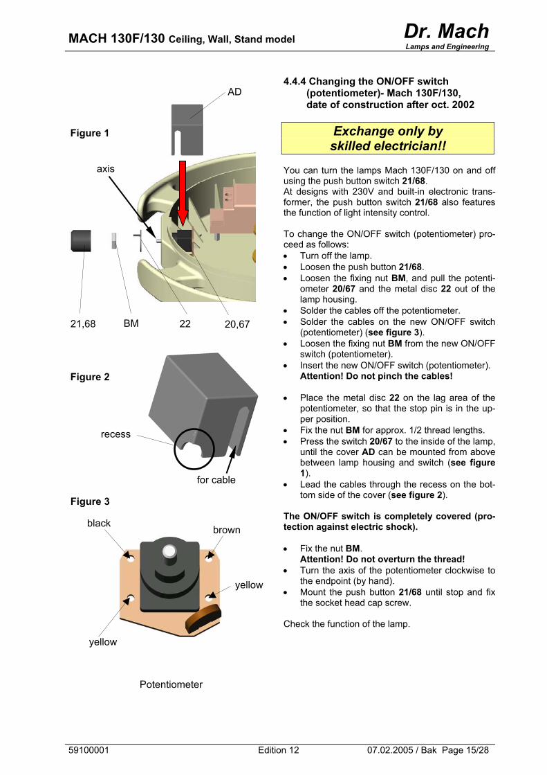
Potentiometer
4.4.4 Changing the ON/OFF switch (potentiometer)- Mach 130F/130, date of construction after oct. 2002
Exchange only by skilled electrician!!
You can turn the lamps Mach 130F/130 on and off using the push button switch 21/68. At designs with 230V and built-in electronic trans-former, the push button switch 21/68 also features the function of light intensity control. To change the ON/OFF switch (potentiometer) pro-ceed as follows: • Turn off the lamp. • Loosen the push button 21/68. • Loosen the fixing nut BM, and pull the potenti-
ometer 20/67 and the metal disc 22 out of the lamp housing.
• Solder the cables off the potentiometer. • Solder the cables on the new ON/OFF switch
(potentiometer) (see figure 3). • Loosen the fixing nut BM from the new ON/OFF
switch (potentiometer). • Insert the new ON/OFF switch (potentiometer).
Attention! Do not pinch the cables!
• Place the metal disc 22 on the lag area of the potentiometer, so that the stop pin is in the up-per position.
• Fix the nut BM for approx. 1/2 thread lengths. • Press the switch 20/67 to the inside of the lamp,
until the cover AD can be mounted from above between lamp housing and switch (see figure 1).
• Lead the cables through the recess on the bot-tom side of the cover (see figure 2).
The ON/OFF switch is completely covered (pro-tection against electric shock). • Fix the nut BM.
Attention! Do not overturn the thread! • Turn the axis of the potentiometer clockwise to
the endpoint (by hand). • Mount the push button 21/68 until stop and fix
the socket head cap screw. Check the function of the lamp.
AD
Figure 1
axis
BM 21,68 22 20,67
Figure 2
for cable
recess
Figure 3
black brown
yellow
yellow
59100001 Edition 12 07.02.2005 / Bak Page 15/28
MACH 130F/130 Ceiling, Wall, Stand model Dr. Mach
Lamps and Engineering
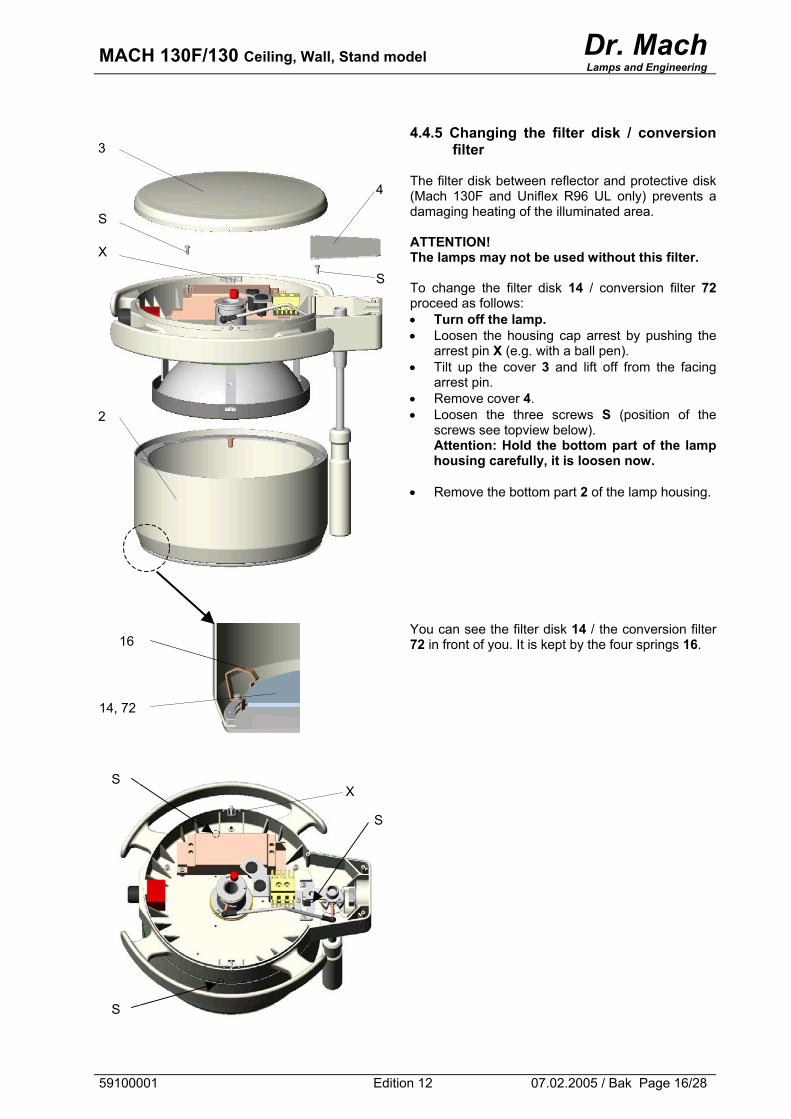
4.4.5 Changing the filter disk / conversion
filter The filter disk between reflector and protective disk (Mach 130F and Uniflex R96 UL only) prevents a damaging heating of the illuminated area. ATTENTION! The lamps may not be used without this filter. To change the filter disk 14 / conversion filter 72 proceed as follows: • Turn off the lamp. • Loosen the housing cap arrest by pushing the
arrest pin X (e.g. with a ball pen). • Tilt up the cover 3 and lift off from the facing
arrest pin. • Remove cover 4. • Loosen the three screws S (position of the
screws see topview below). Attention: Hold the bottom part of the lamp housing carefully, it is loosen now.
• Remove the bottom part 2 of the lamp housing.
You can see the filter disk 14 / the conversion filter 72 in front of you. It is kept by the four springs 16.
S
4
3
S
X
2
16
14, 72
X S
S
S
59100001 Edition 12 07.02.2005 / Bak Page 16/28
MACH 130F/130 Ceiling, Wall, Stand model Dr. Mach
Lamps and Engineering
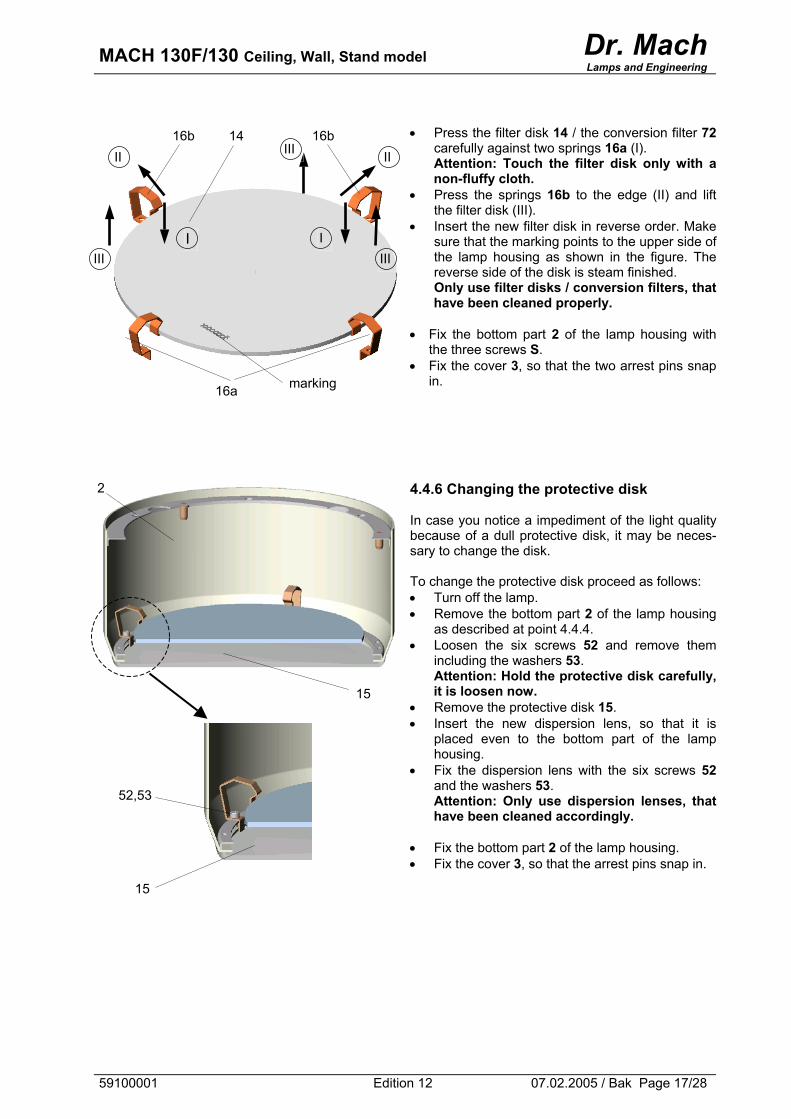
• Press the filter disk 14 / the conversion filter 72
carefully against two springs 16a (I). Attention: Touch the filter disk only with a non-fluffy cloth.
• Press the springs 16b to the edge (II) and lift the filter disk (III).
• Insert the new filter disk in reverse order. Make sure that the marking points to the upper side of the lamp housing as shown in the figure. The reverse side of the disk is steam finished. Only use filter disks / conversion filters, that have been cleaned properly.
• Fix the bottom part 2 of the lamp housing with
the three screws S. • Fix the cover 3, so that the two arrest pins snap
in.
4.4.6 Changing the protective disk In case you notice a impediment of the light quality because of a dull protective disk, it may be neces-sary to change the disk. To change the protective disk proceed as follows: • Turn off the lamp. • Remove the bottom part 2 of the lamp housing
as described at point 4.4.4. • Loosen the six screws 52 and remove them
including the washers 53. Attention: Hold the protective disk carefully, it is loosen now.
• Remove the protective disk 15. • Insert the new dispersion lens, so that it is
placed even to the bottom part of the lamp housing.
• Fix the dispersion lens with the six screws 52 and the washers 53. Attention: Only use dispersion lenses, that have been cleaned accordingly.
• Fix the bottom part 2 of the lamp housing. • Fix the cover 3, so that the arrest pins snap in.
III 14 16b
I
16b
I
II II
III III
marking 16a
2
15
52,53
15
59100001 Edition 12 07.02.2005 / Bak Page 17/28
MACH 130F/130 Ceiling, Wall, Stand model Dr. Mach
Lamps and Engineering
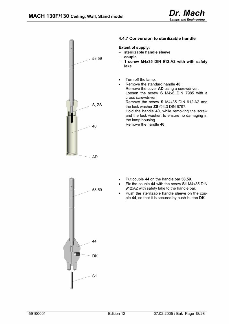
4.4.7 Conversion to sterilizable handle Extent of supply: − sterilizable handle sleeve − couple − 1 screw M4x35 DIN 912:A2 with with safety
lake • Turn off the lamp. • Remove the standard handle 40:
Remove the cover AD using a screwdriver. Loosen the screw S M4x6 DIN 7985 with a cross screwdriver. Remove the screw S M4x35 DIN 912:A2 and the lock washer ZS ∅4,3 DIN 6797. Hold the handle 40, while removing the screw and the lock washer, to ensure no damaging in the lamp housing. Remove the handle 40.
• Put couple 44 on the handle bar 58,59. • Fix the couple 44 with the screw S1 M4x35 DIN
912:A2 with safety lake to the handle bar. • Push the sterilizable handle sleeve on the cou-
ple 44, so that it is secured by push-button DK.
58,59
S, ZS
40
AD
58,59
44
DK
S1
59100001 Edition 12 07.02.2005 / Bak Page 18/28
MACH 130F/130 Ceiling, Wall, Stand model Dr. Mach
Lamps and Engineering
5. Data
5.1 Technical data
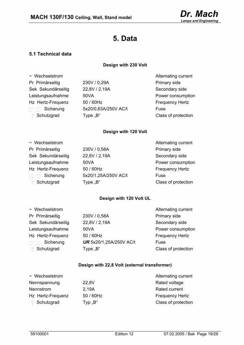
Design with 230 Volt
~ Wechselstrom Alternating current Pr Primärseitig 230V / 0,29A Primary side Sek Sekundärseitig 22,8V / 2,19A Secondary side Leistungsaufnahme 50VA Power consumption Hz Hertz-Frequenz 50 / 60Hz Frequency Hertz Sicherung 5x20/0,63A/250V AC/t Fuse Schutzgrad Type „B“ Class of protection
Design with 120 Volt
~ Wechselstrom Alternating current Pr Primärseitig 230V / 0,58A Primary side Sek Sekundärseitig 22,8V / 2,19A Secondary side Leistungsaufnahme 50VA Power consumption Hz Hertz-Frequenz 50 / 60Hz Frequency Hertz Sicherung 5x20/1,25A/250V AC/t Fuse Schutzgrad Type „B“ Class of protection
Design with 120 Volt UL
~ Wechselstrom Alternating current Pr Primärseitig 230V / 0,58A Primary side Sek Sekundärseitig 22,8V / 2,19A Secondary side Leistungsaufnahme 50VA Power consumption Hz Hertz-Frequenz 50 / 60Hz Frequency Hertz Sicherung UR 5x20/1,25A/250V AC/t Fuse Schutzgrad Type „B“ Class of protection
Design with 22,8 Volt (external transformer)
~ Wechselstrom Alternating current Nennspannung 22,8V Rated voltage Nennstrom 2,19A Rated current Hz Hertz-Frequenz 50 / 60Hz Frequency Hertz Schutzgrad Typ „B“ Class of protection
59100001 Edition 12 07.02.2005 / Bak Page 19/28
MACH 130F/130 Ceiling, Wall, Stand model Dr. Mach
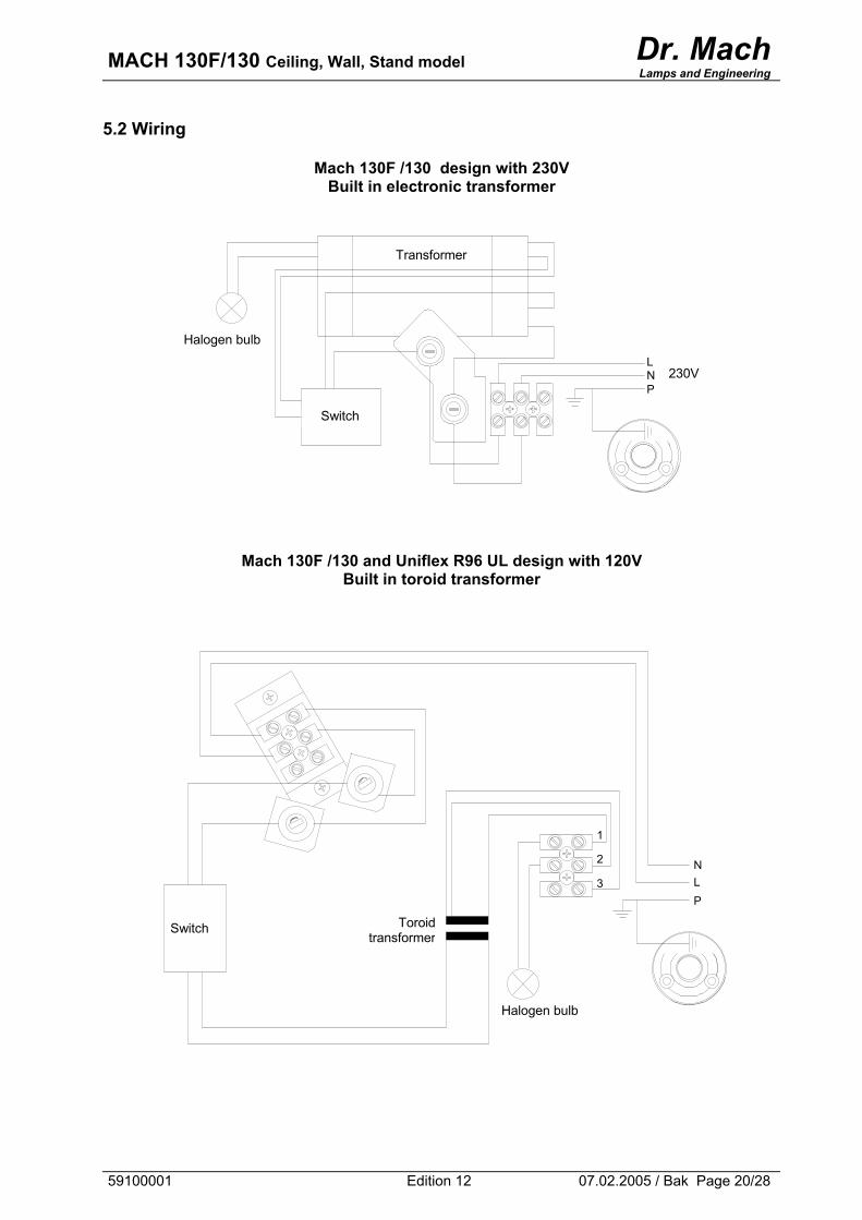
Lamps and Engineering 5.2 Wiring
Mach 130F /130 design with 230V Built in electronic transformer
Transformer
Halogen bulb
P N L
230V
Switch
Mach 130F /130 and Uniflex R96 UL design with 120V Built in toroid transformer
1
2 N L 3 P
Toroidtransformer
Switch
Halogen bulb
59100001 Edition 12 07.02.2005 / Bak Page 20/28
MACH 130F/130 Ceiling, Wall, Stand model Dr. Mach
Lamps and Engineering
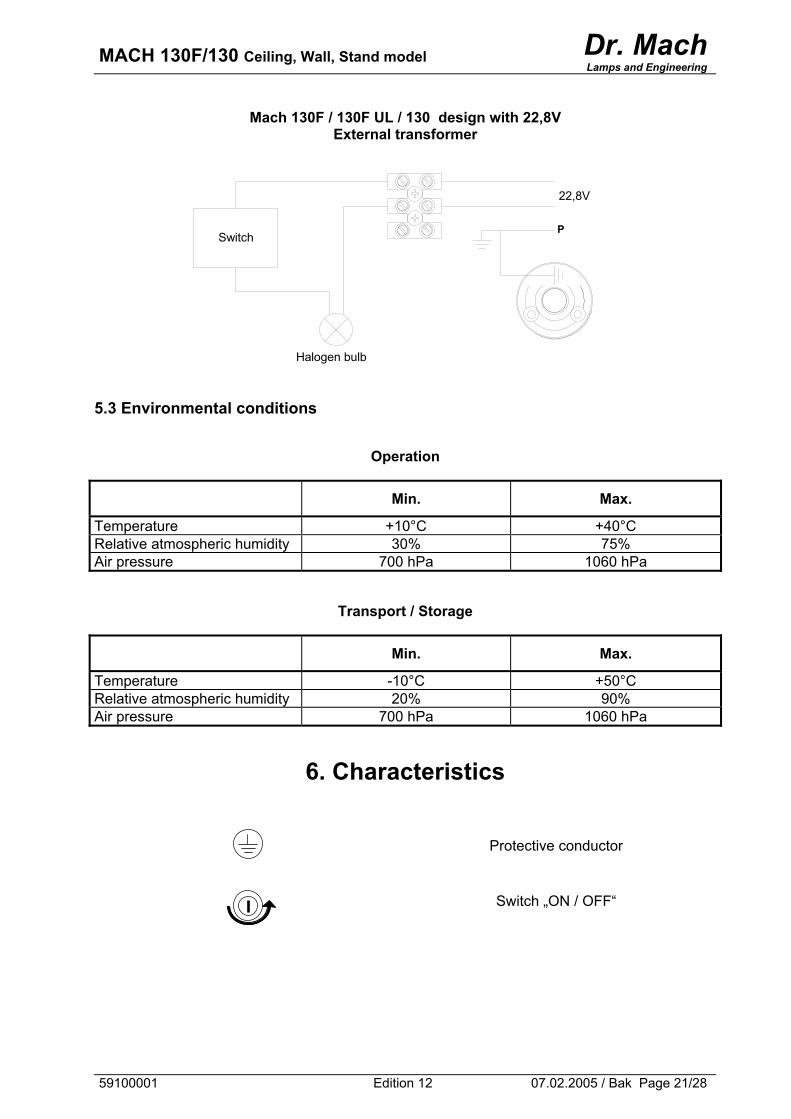
Mach 130F / 130F UL / 130 design with 22,8V External transformer
22,8V
P Switch
Halogen bulb
5.3 Environmental conditions
Operation
Min. Max.
Temperature +10°C +40°C Relative atmospheric humidity 30% 75% Air pressure 700 hPa 1060 hPa
Transport / Storage
Min. Max.
Temperature -10°C +50°C Relative atmospheric humidity 20% 90% Air pressure 700 hPa 1060 hPa
6. Characteristics
Protective conductor
Switch „ON / OFF“
59100001 Edition 12 07.02.2005 / Bak Page 21/28
MACH 130F/130 Ceiling, Wall, Stand model Dr. Mach
Lamps and Engineering
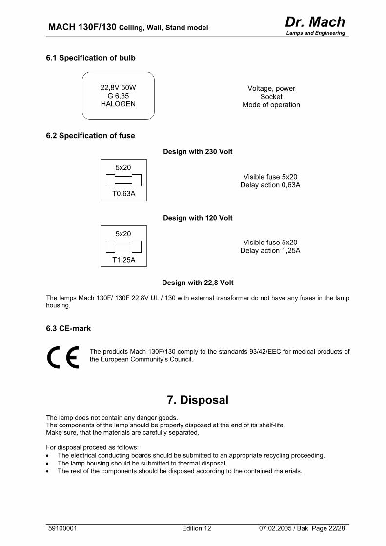
6.1 Specification of bulb
Voltage, power Socket
Mode of operation
22,8V 50W G 6,35
HALOGEN
6.2 Specification of fuse
Design with 230 Volt
Visible fuse 5x20 Delay action 0,63A
T0,63A
5x20
Design with 120 Volt
Visible fuse 5x20 Delay action 1,25A
T1,25A
5x20
Design with 22,8 Volt
The lamps Mach 130F/ 130F 22,8V UL / 130 with external transformer do not have any fuses in the lamp housing. 6.3 CE-mark
The products Mach 130F/130 comply to the standards 93/42/EEC for medical products of the European Community’s Council.
7. Disposal The lamp does not contain any danger goods. The components of the lamp should be properly disposed at the end of its shelf-life. Make sure, that the materials are carefully separated. For disposal proceed as follows: • The electrical conducting boards should be submitted to an appropriate recycling proceeding. • The lamp housing should be submitted to thermal disposal. • The rest of the components should be disposed according to the contained materials.
59100001 Edition 12 07.02.2005 / Bak Page 22/28
MACH 130F/130 Ceiling, Wall, Stand model Dr. Mach
Lamps and Engineering
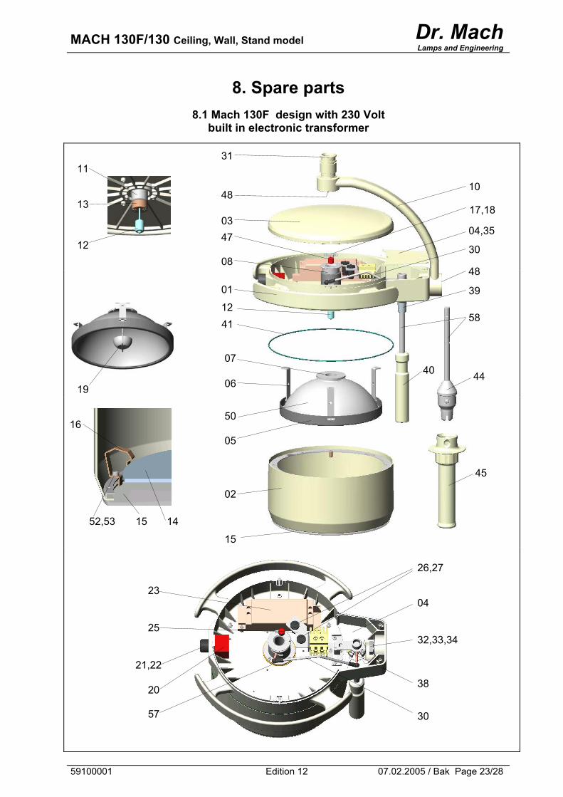
8. Spare parts
8.1 Mach 130F design with 230 Volt built in electronic transformer
11
13
12
19
14 15
1241
17,18
15
02
05
50
06
07
01
08
4703
48
31
45
40 44
58
39
48
30
04,35
10
52,53
16
30
38
32,33,34
04
26,27
57
20
21,22
25
23
59100001 Edition 12 07.02.2005 / Bak Page 23/28
MACH 130F/130 Ceiling, Wall, Stand model Dr. Mach
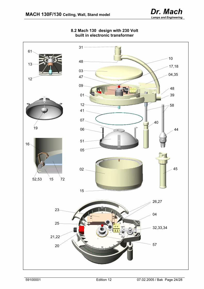
Lamps and Engineering
8.2 Mach 130 design with 230 Volt built in electronic transformer
61
13
12
31
10
04,35
48
48
03 47
12
09
41
02
16
39
17,18
19
05
51
06
07
01
40
58
44
45
15 72 52,53
15
57
32,33,34
04
26,27
20
21,22
25
23
59100001 Edition 12 07.02.2005 / Bak Page 24/28
MACH 130F/130 Ceiling, Wall, Stand model Dr. Mach
Lamps and Engineering
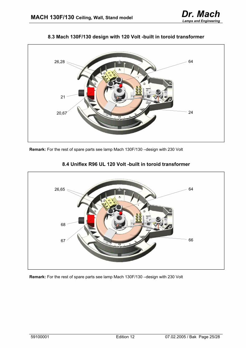
8.3 Mach 130F/130 design with 120 Volt -built in toroid transformer
64
20,67
26,28
21
24
Remark: For the rest of spare parts see lamp Mach 130F/130 –design with 230 Volt
8.4 Uniflex R96 UL 120 Volt -built in toroid transformer
64 26,65
68
66 67
Remark: For the rest of spare parts see lamp Mach 130F/130 –design with 230 Volt
59100001 Edition 12 07.02.2005 / Bak Page 25/28
MACH 130F/130 Ceiling, Wall, Stand model Dr. Mach
Lamps and Engineering
8.5 Mach 130F/130 design with 22,8 Volt -external transformer Remark: For spare parts see lamp 130F/130 (design with 230V), excepting the electronic transformer, the fuses and the fuse holders.
8.6 Mach 130F UL design with 22,8 Volt -external transformer Remark: For spare parts see lamp Uniflex R96 UL (design with 22,8V), excepting the toroid transformer, the fuses and the fuse holders.
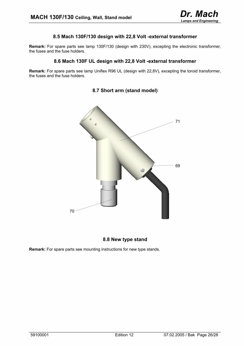
8.7 Short arm (stand model)
71
69
70
8.8 New type stand Remark: For spare parts see mounting instructions for new type stands.
59100001 Edition 12 07.02.2005 / Bak Page 26/28
MACH 130F/130 Ceiling, Wall, Stand model Dr. Mach
Lamps and Engineering
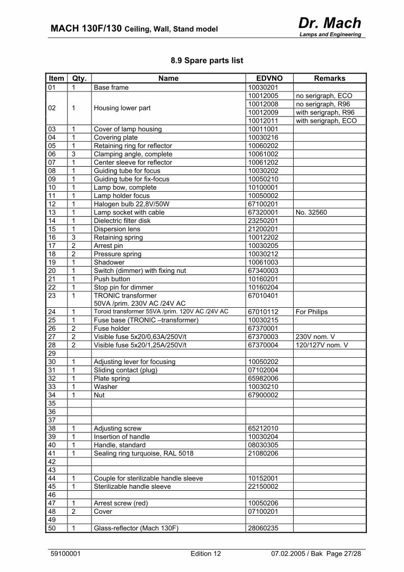
8.9 Spare parts list
Item Qty. Name EDVNO Remarks 01 1 Base frame 10030201
10012005 no serigraph, ECO 10012008 no serigraph, R96 10012009 with serigraph, R96 02 1 Housing lower part
10012011 with serigraph, ECO 03 1 Cover of lamp housing 10011001 04 1 Covering plate 10030216 05 1 Retaining ring for reflector 10060202 06 3 Clamping angle, complete 10061002 07 1 Center sleeve for reflector 10061202 08 1 Guiding tube for focus 10030202 09 1 Guiding tube for fix-focus 10050210 10 1 Lamp bow, complete 10100001 11 1 Lamp holder focus 10050002 12 1 Halogen bulb 22,8V/50W 67100201 13 1 Lamp socket with cable 67320001 No. 32560 14 1 Dielectric filter disk 23250201 15 1 Dispersion lens 21200201 16 3 Retaining spring 10012202 17 2 Arrest pin 10030205 18 2 Pressure spring 10030212 19 1 Shadower 10061003 20 1 Switch (dimmer) with fixing nut 67340003 21 1 Push button 10160201 22 1 Stop pin for dimmer 10160204 23 1 TRONIC transformer
50VA /prim. 230V AC /24V AC 67010401
24 1 Toroid transformer 55VA /prim. 120V AC /24V AC 67010112 For Philips 25 1 Fuse base (TRONIC –transformer) 10030215 26 2 Fuse holder 67370001 27 2 Visible fuse 5x20/0,63A/250V/t 67370003 230V nom. V 28 2 Visible fuse 5x20/1,25A/250V/t 67370004 120/127V nom. V 29 30 1 Adjusting lever for focusing 10050202 31 1 Sliding contact (plug) 07102004 32 1 Plate spring 65982006 33 1 Washer 10030210 34 1 Nut 67900002 35 36 37 38 1 Adjusting screw 65212010 39 1 Insertion of handle 10030204 40 1 Handle, standard 08030305 41 1 Sealing ring turquoise, RAL 5018 21080206 42 43 44 1 Couple for sterilizable handle sleeve 10152001 45 1 Sterilizable handle sleeve 22150002 46 47 1 Arrest screw (red) 10050206 48 2 Cover 07100201 49 50 1 Glass-reflector (Mach 130F) 28060235
59100001 Edition 12 07.02.2005 / Bak Page 27/28
MACH 130F/130 Ceiling, Wall, Stand model Dr. Mach
Lamps and Engineering
59100001 Edition 12 07.02.2005 / Bak Page 28/28
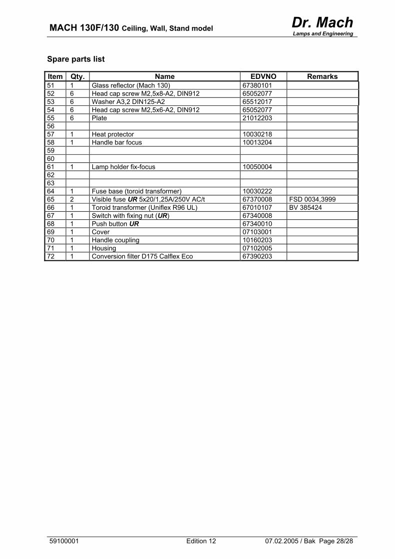
Spare parts list Item Qty. Name EDVNO Remarks 51 1 Glass reflector (Mach 130) 67380101 52 6 Head cap screw M2,5x8-A2, DIN912 65052077 53 6 Washer A3,2 DIN125-A2 65512017 54 6 Head cap screw M2,5x6-A2, DIN912 65052077 55 6 Plate 21012203 56 57 1 Heat protector 10030218 58 1 Handle bar focus 10013204 59 60 61 1 Lamp holder fix-focus 10050004 62 63 64 1 Fuse base (toroid transformer) 10030222 65 2 Visible fuse UR 5x20/1,25A/250V AC/t 67370008 FSD 0034,3999 66 1 Toroid transformer (Uniflex R96 UL) 67010107 BV 385424 67 1 Switch with fixing nut (UR) 67340008 68 1 Push button UR 67340010 69 1 Cover 07103001 70 1 Handle coupling 10160203 71 1 Housing 07102005 72 1 Conversion filter D175 Calflex Eco 67390203