machine control for graders - leica geosystems...beside machine control systems for graders, leica...
TRANSCRIPT

Machine Control for Graders

Grading done efficiently and with precision
The basic upgradable Machine Control Systemby Leica Geosystems controls the blade auto-matically. It assures smooth grading results andenormous material savings. Even manpowerrequirements are drastically reduced.
Applications for the basic Control System (slope, laser, ultra sonic)
• Streets and paths.• Parking lots and flat hall floors or floors with an even
slope.• Areas with fixed points or fixed lines, such as trenches
or road edges.
Your advantage
Leica Geosystems Machine Control System for Gradersmeets all demands. It combines the strengths of MOBA' sbasic GS-496 Control System with the advantages of a 3D high-end Control System.
Higher precision• Precise, remotely copying of reference heights by the
MOBA Sonic-Ski.• Smoothly graded surfaces.• Material is graded to mm precision, enabling total cost
control .• Increases overall precision.
Time savings• Slope checks are not required while grading.• Fewer work-steps are required.• Grade more material within less time.
Cost advantages• Only the driver is required for grading (3D solution).• No surveying costs for stake outs, guide wires and check
measurements (3D solution).• Material requirements can be precisely calculated and
controlled.• Reduced construction time as daily efficiency is
improved.
Flexibility• Can be used in just about any topography.• Easy interchange between basic and 3D-Guidance
Systems.• Interchangeable laser, ultra sonic, 3D total stations and
GPS sensors.• Easy to down or upgrade.• Can be used with almost all machine types.
Reliability• All components mounted on the outside of the machine
are robust and completely molded on. • The machine computer meets the highest quality
standards (EN550022 [FCC151] class B).• CAN connection optimizes data-flow to all sensors by
digital transfer.
Easy to operate• Almost every function can be performed from the same
control panel.• Clear display of all required information for the driver.• Automatic height and slope control relieves the driver.
Rotation compensatorExact data of the defaultrotation provides optimalslope compensation.
MultisticksEnables hands-on controlof the system with thehydraulic control levels.
Slope sensorDetermines the currentposition of the blade forprecise slope control.
Sonic-Ski height sensorUsing 6 resonators makesit the most precise remotely controlled ultrasonic sensor.
Laser receiver LS-250High precision linear laserscanner without electricmast or mast control.
Control panelThe machine's currentstatus at a glance.
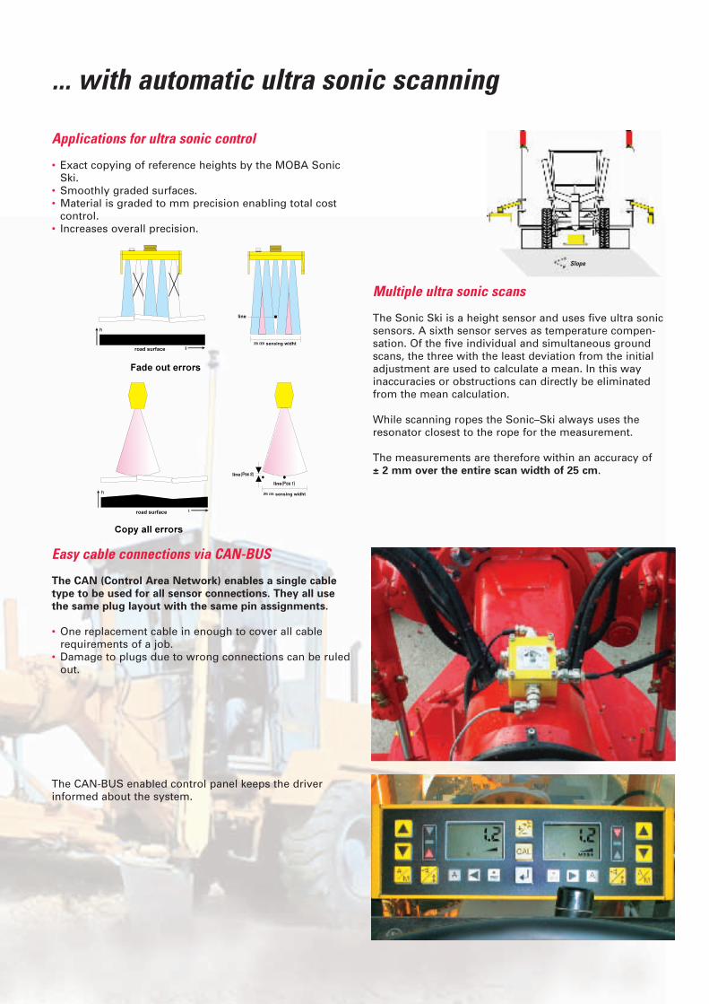
... with automatic ultra sonic scanning
Applications for ultra sonic control
• Exact copying of reference heights by the MOBA SonicSki.
• Smoothly graded surfaces.• Material is graded to mm precision enabling total cost
control.• Increases overall precision.
Multiple ultra sonic scans
The Sonic Ski is a height sensor and uses five ultra sonicsensors. A sixth sensor serves as temperature compen-sation. Of the five individual and simultaneous groundscans, the three with the least deviation from the initialadjustment are used to calculate a mean. In this way inaccuracies or obstructions can directly be eliminatedfrom the mean calculation.
While scanning ropes the Sonic–Ski always uses the resonator closest to the rope for the measurement.
The measurements are therefore within an accuracy of ± 2 mm over the entire scan width of 25 cm.
Easy cable connections via CAN-BUS
The CAN (Control Area Network) enables a single cabletype to be used for all sensor connections. They all usethe same plug layout with the same pin assignments.
• One replacement cable in enough to cover all cablerequirements of a job.
• Damage to plugs due to wrong connections can be ruledout.
The CAN-BUS enabled control panel keeps the driver informed about the system.
Str
Slope

... with automatic laser control
Proportional laser receiver LS-250
The LS-250 laser receiver is a linear sensor for height measurements that works with the known rotation laserssuch as red light emitters (Helium, Neon) and infraredemitters.
Unlike conventional multi-channel receivers that only havea few sections within each receiving range, the LS-250evaluates every single receiver cell. It is possible to freelyselect and shift the receiving sections. Every deviation isrecorded with an accuracy of 1 mm making proportionalcontrol according to the deviations possible. Electronicmasts and mast control are no longer required.
Dual slope laser
Dual slope lasers are best suited to control a grader withthe proportional receiver LS-250.
Robust self-levelling rotation lasers like the LB-4 or theJavelin have a large working range and steep slopes (up to ±10% respectively ±20%) can be entered for bothaxis (Javelin-s up to ±50%).In addition, they have selectable, high rotation speed forperfect control of graders.

... with the automatic 3D total station
Leica Geosystems uses precise automatic Total Stationsto control Graders.
Depending on accuracy requirements, all TCA, TCRAmodels of the TPS 1100 series, as well as TCA1800 of theTPS1000 series can be used. The Total Station communi-cates via radio to the robust computer on the machine and measures the exact 3D position of the prism on themachine. Combined with the measured data collected bythe slope sensors, the position and orientation of themachine is constantly updated. By comparing the projectdata saved in the machine computer, the design correctionfor height and slope are calculated and transferred to theblade controller.
The high degree of system utility is reflected in the following characteristics:
• Can be used in just about any topography.• Easy interchange between basic and 3D Control
Systems.• Interchangeable laser, ultra sonic, 3D total stations
and GPS sensors.• Easy to down or upgrade.• Can be used with almost all machine types.
Applications for 3D Control
• Large projects with frequently changing slopes.• Projects with complex designs such as windings,
elevations, clothoids...• Projects with large earth moving requirements.

... by 3D TPS position measurements
Mast slope sensor
The Leica 3D Control software combined with the mastslope sensor permits the driver to adjust the blade angleto suit the job at hand.
The software automatically recognizes the direction of travel of the machine eliminating the need for making a manual switchover. With half of the blade grading can be done beyond the edge of the project. The data model is a simple ASCII file that any CAD program can generate. The project data of the entire project only has to be transferred to the machine computer once.
The Leica Machine Control System for Graders meets all requirements. It combines the strengths of the basic GS 496 Control System by MOBA with the advantages of high-end 3D Control.
With Automatic Target Recognition (ATR) and intelligentsearch routines the Total Stations quickly and reliably findthe target on the machine. The target is a simple prismwithout any additional electronics.
The Leica 3D solution with automatic Total Station andLMGS-G software, makes the very precise Machine Control System for Graders possible.
System accuracy of ±5 mm in height and ±10 mm in position is attainable. A homogeneous grading job is theresult. Straight forward or difficult street designs can begraded according to the projected parameters.

The system accuracy is within the accuracy range of GPSsystems, meaning that ± 30 mm in position and height isattainable. One time system set-up permits around-the-clock operations. GPS is well suited to prepare constructionsites and for large earth moving requirements.
The extremely robust machine computer with touch screenis ideally suited for harsh construction site conditions. It is resistant to dust, humidity, splash-water (IP65) and ishighly immune to vibrations. All components inside, eventhe processor are soldered in place, not just plugged in andcoated with a protective layer of lacquer.
... using 3D GPS position measurements
The GPS System 500 can be used instead of the total station. The position of the GPS antenna on the mast isdetermined and the GPS measurements are processed in the machine computer. The type of data is different when compared with the Total Station, but the processingis the same. This enables the easy interchange betweenGPS and TPS sensors.
The MC500 sensor with its robust, vibration-resistant casingis mounted on the machine and used as the rover station. A SR530 is set-up as the reference station. Only with thereference station is the high degree of precision possible, asthe position of the rover station (on the machine) is alwayscalculated relative to the known position of the referencestation.
A single reference station is enough to cover a constructionsite of 10 x 10 kms and to guide any desired number ofmachines with that reference signal.
Decades of experience
The close cooperation with the control systems manufacturer MOBA, has put decades of experience atLeica's disposal. MOBA technologies are cutting-edge.
The CAN bus system for data transfer has become thestandard it has been for years in the automobile manu-facturing industry.
MOBA's ultra sonic sensor (Sonic Ski) and the laser receiver LS-250 have unique features that enormouslyincrease grading precision. "Cross coupling" enables parallel changes in height and slope control, considerablyspeeding up blade control.
Leica Geosystems as survey specialists provides the required instruments for 3D upgrades.
Total Stations and GPS for Machine Control applicationsare standard products that can be used for all typical surveying jobs. The Leica system makes it possible tointerchange the sensors depending on application. Thesensors only have to be plugged-in and the CAN bussystem initiates them.

Illustrations, descriptions and technical data are not binding and may bechanged. Printed in Switzerland.Copyright Leica Geosystems AG, Heerbrugg, Switzerland, 2002
Leica Geosystems AGCH-9435 Heerbrugg
(Switzerland)Phone +41 71 727 31 31
Fax +41 71 727 46 73www.leica-geosystems.com
Total Quality Management - Our commitment to totalcustomer satisfaction
Ask your local LeicaGeosystems agent for more information about our TQM program.
We are always at your disposal
• We offer support with project planing and system installation.
• We offer total solutions.• We offer solutions to your specifications.• We offer worldwide service.
Beside Machine Control Systems for Graders, Leica Geosystems offers solutions for other automaticconstruction machines such as Slip-form Pavers,Trimmers, Pavers and Bulldozers.
Construction laser- our lasers are alwaysbuilt to meet the demands of constructionsites, no matter what they are used for:the construction of high-rise buildings, fordigging trenches, for machine guidance orinterior construction.
Automatic levels – professional opticallevels are built for the construction site.They are quickly set-up, very precise andtop every comparison of price to perfor-mance ratios.
Leading in GPS and TPS technology – usedworldwide in projects that demand the highest standards, designed for variousapplications and to be easy-to-use. Wedeveloped the first reflectorless total stations in 1998 and our experience withGPS dates back to 1967. We hold severalpatents and were first at introducing manynew technologies to the industry.
Software and accessories – integratedsoftware solutions and a complete seriesof tripods, staffs, our patented 360°prisms, batteries, chargers, everythingyou need to extract the best performancefrom your instrument.
Hand-held Laser Distance Meter - Simpleand handy tool to determine distances,areas and volumes quickly and accurately,indoors and outdoors.
DIGI System - The location system provides a fast and safe solution for tracing buried utility services.
Your dealer:
The machine control systemfor graders was developedwith the assistance of MOBAMobilautomation GmbH.
Distancer and ATR:Laser class 1 in accordance with IEC 60825-1 and EN 60825-1Laser class I in accordance with FDA 21 CFR Ch. I § 1040
Laser plummet:Laser class 2 in accordance with IEC 60825-1 and EN 60825-1Laser class II in accordance with FDA 21 CFR Ch. I § 1040
Electronic guide light:Laser class 1 in accordance with IEC 60825-1 and EN 60825-1
731277en – XII.02 – RDV