machine dra wing
TRANSCRIPT

[N- ]
Roll No. Total No. of Pages : 07Total No. of Questions : 09
B.Tech. (AE) (Sem.–3rd)MACHINE DRAWING
Subject Code : BTAE-306 (2011 Batch)Paper ID : [A1156]
Time : 3 Hrs. Max. Marks : 60
INSTRUCTION TO CANDIDATES :1. SECTION-A is COMPULSORY consisting of TEN questions carrying
TWO marks each.2. SECTION-B contains FIVE questions carrying FIVE marks each and
students has to attempt any FOUR questions.3. SECTION-C contains THREE questions carrying TEN marks each and
students has to attempt any TWO questions.
SECTION-A
l. Write briefly :
a. What do you mean by the term caulking?
b. Acme thread is combination of ........... and ............ type of thread.
c. Name any two ways of locking the nuts on bolts.
d. What is the use of Union pipe joint in a piping circuit?
e. Draw the symbols for the following welded joints along with theillustrations.
i) Single V-Butt Weld
ii) Square Weld
f. Name any two types of pipe joints.
g. What material is preferred for brasses in Plummer Block and why?
h. Name two parts rotating parts in an IC engine.
i. What is the function of steam stop valve?
j. Which type of thread is used in Screw jack applications and why?
2- 1854
www.brp
aper
.com
www.brp
aper
.com
[N- ]2- 1854
SECTION-B
2. Draw free hand proportionate neat sketches for the following :a. Rag Foundation Bolt.b. Use of lock nut for locking.
3. Draw Plan of triple riveted lap joint (zigzag type) for connecting twoplates of thickness 9 mm. Use appropriate empirical relations and showat least 2 rivet heads along each row of rivets. Use Pan head rivets in thejoint.
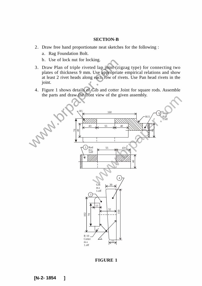
4. Figure 1 shows details of Gib and cotter Joint for square rods. Assemblethe parts and draw the front view of the given assembly.
70 40
160
43 55 40
R5
R15
40
1 Strapm.s1.off
55 43
40
2 Rodm.s1off
3
=
102
70
4
30
15052
22
R 10Cotterm.s1.off
Grbm.s1.off
13
FIGURE 1
www.brp
aper
.com
www.brp
aper
.com
[N- ]2- 1854
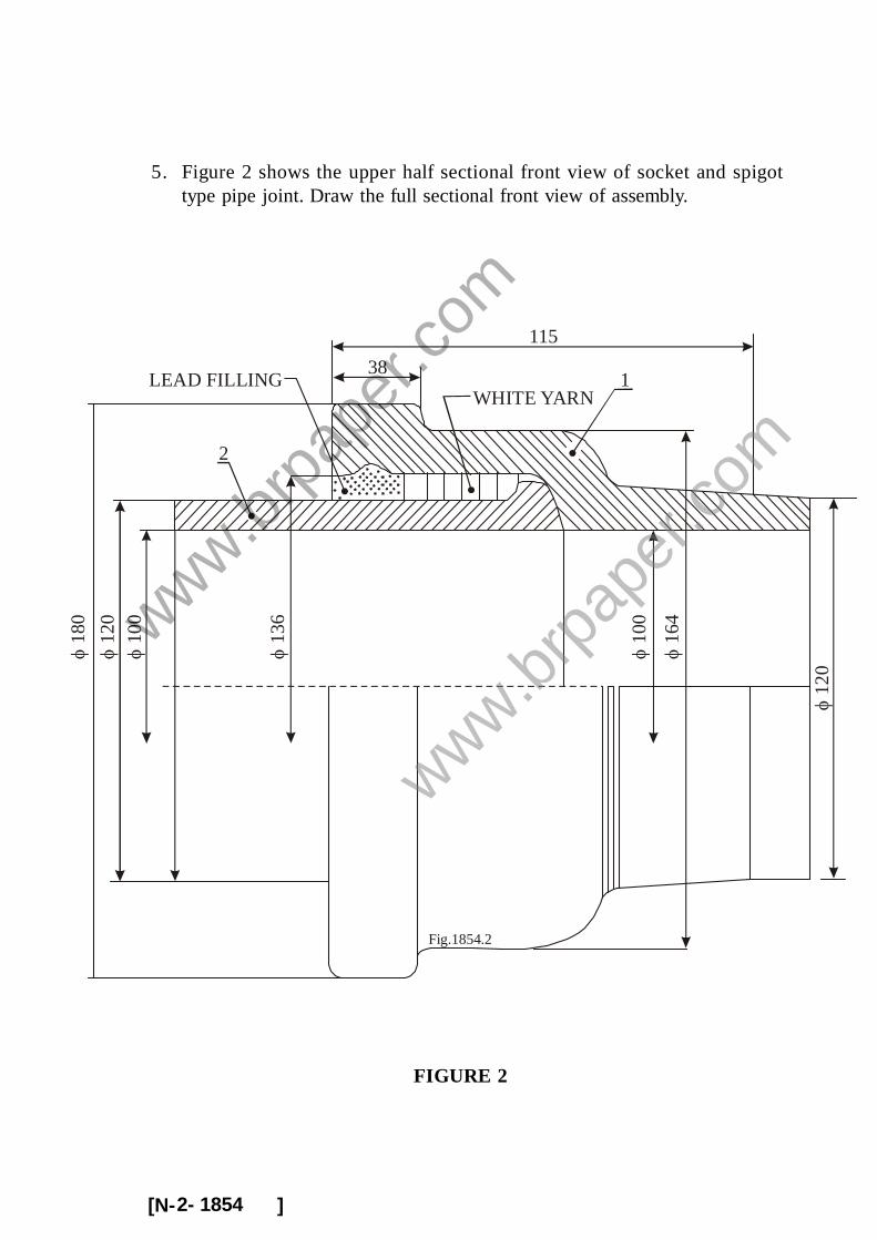
5. Figure 2 shows the upper half sectional front view of socket and spigottype pipe joint. Draw the full sectional front view of assembly.
FIGURE 2
12
0
10
0
1WHITE YARN
38
2
LEAD FILLING
16
4
13
6
10
0
120
18
0
115
Fig.1854.2
www.brp
aper
.com
www.brp
aper
.com
[N- ]2- 1854
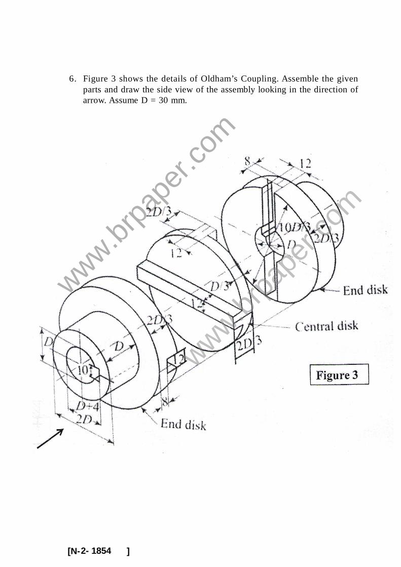
6. Figure 3 shows the details of Oldham’s Coupling. Assemble the givenparts and draw the side view of the assembly looking in the direction ofarrow. Assume D = 30 mm.
www.brp
aper
.com
www.brp
aper
.com

[N- ]2- 1854
SECTION-C
7. Figure 4 shows the partial details of Plummer Block. Assemble the givencomponents and draw the full sectional front view of assembly.
FIGURE 4
www.brp
aper
.com
www.brp
aper
.com

[N- ]2- 1854
8. Figure 5 shows the details of Crane Hook. Assemble the given componentsand draw the front view of assembly. Hook details up to section markedas c-c may be shown in the assembly.
www.brp
aper
.com
www.brp
aper
.com

[N- ]2- 1854
9. Figure 6 shows the partial details of 50 mm steam stop valve. Assemblethe given components and draw the full sectional front view of assembly.
FIGURE 6
127
6
50 1313
13
60×2M
13 70
90
50
C21
19 19
C
193
98
19
164
156
19
82 172
13
4 HOLES, 18, ON126 PCD, OFF CENTRE LINES
4-HOLES, 16TAPPED 19DEEP,ON 132 P.C.D
10 67
5743
VALVE G.M. 1.0FF
VALVE SEATG.M. 1.0FF
5
48
333
45°
815
10
21
10
27M60 × 2 1625
250
445° 519
164
BODYCI, I.OFF
AA
www.brp
aper
.com
www.brp
aper
.com