mackinac hvdc construction and testing - umn ccaps · pdf file–north and south sides...
TRANSCRIPT
atcllc.com
Mackinac HVDC Construction and Testing
Michael B. Marz
MIPSYCON
November 5, 2014

2
• Back-to-Back VSC
• Controls Flow between
Michigan Peninsulas to
Allow Maintenance Outages
• Control Challenges: Weak
System and No RAS/SPS
• Compressed Schedule
• Operational Summer 2014
• Design, Construction,
Testing and Operation
Mackinac HVDC

The Need for Flow Control
• Weak UP & LP Systems
Carry Some W-E Bias Flow
• Thermal & Voltage Issues
• Fix by Splitting System
(Re-dispatch Impractical)
• Once Rare Later Common
• Split Deferred Maintenance
• Upgrading System Too
Expensive and Not Timely
3
4
• Requirements – Control Power Flows
– Operate Under Weak System Conditions
– Not Exacerbate (Mitigate?) Area Voltage Issues
• Concerns – Cost, Losses and Maintenance Outages
– Operation During Faults and Outages
– Robustness – System Changes Can’t Make Obsolete
– No SPS, Only Use Local Measurements to Protect
Equipment and Maintain Stability
Project Requirements & Concerns

5
Technology Selection
• Alternatives Considered – Series Reactors
– Phase Shifting/Variable Frequency Transformers
– Line Commutated/Voltage Source Converter HVDC
• Advantages of VSC HVDC – Can Operate Under Minimal Short Circuit Level
– Can Control Flow Regardless of System Changes
– Provides Dynamic Vars Independently at Each Terminal
– With Terminals Disconnected Can Act as Two STATCOMs
– Fast Real & Reactive Power Response to Contingencies
– Can Help Damp System Oscillations
– Islanded Operation and Blackstart Capability
– Eliminate Need for Special Protection System?
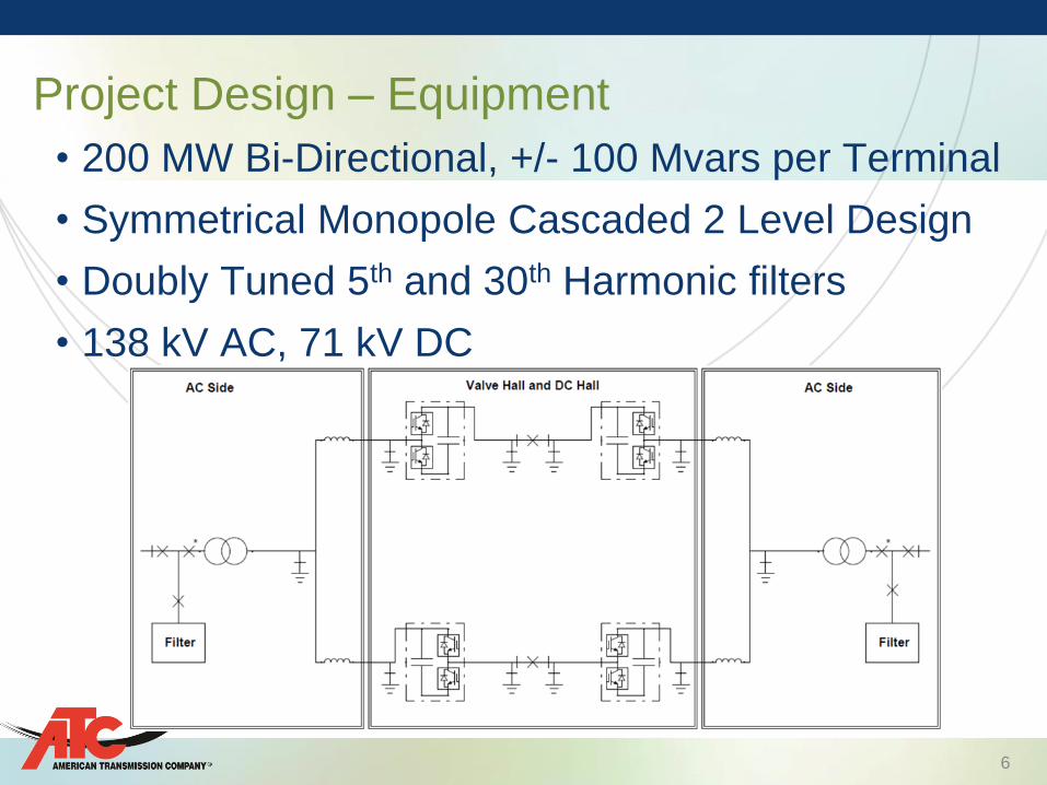
• 200 MW Bi-Directional, +/- 100 Mvars per Terminal
• Symmetrical Monopole Cascaded 2 Level Design
• Doubly Tuned 5th and 30th Harmonic filters
• 138 kV AC, 71 kV DC
Project Design – Equipment
6

7
Two Level & Cascaded Two Level Topology
7

8
• Voltage Like Modular Multi-Level Converter rather than
Two Level Converter
Two Level Converter Voltage
Cascaded Two Level Converter Voltage
Cascaded Two Level Design
9
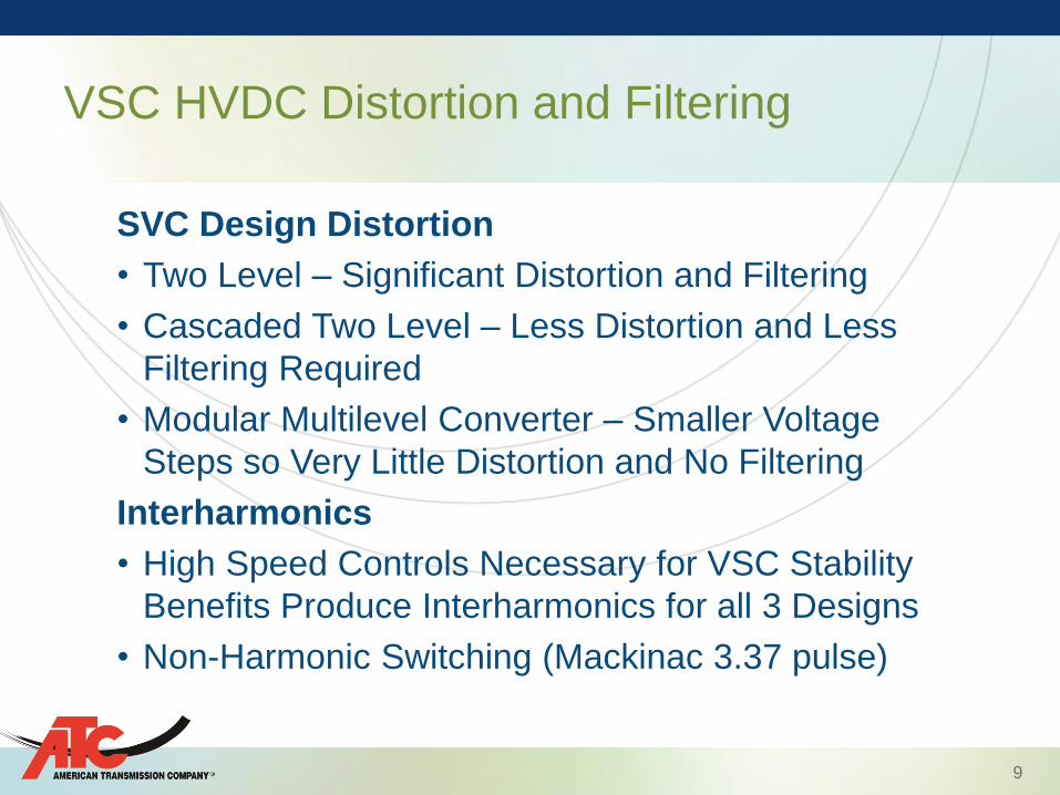
SVC Design Distortion
• Two Level – Significant Distortion and Filtering
• Cascaded Two Level – Less Distortion and Less
Filtering Required
• Modular Multilevel Converter – Smaller Voltage
Steps so Very Little Distortion and No Filtering
Interharmonics
• High Speed Controls Necessary for VSC Stability
Benefits Produce Interharmonics for all 3 Designs
• Non-Harmonic Switching (Mackinac 3.37 pulse)
VSC HVDC Distortion and Filtering

10
• South Converter – Vector Current Control – Instantaneous P & Q Controlled Independently
– Fast Inner Control Loop Decouples Current (q & d)
– Outer Loop uses d for P or DC voltage and q for Q or AC
voltage control
• North (Weak System) Converter – Phasor Voltage Control – Direct Control of Converter’s Internal AC Voltage Magnitude
and Phase
– Magnitude Control Extended to PCC by Impedance Correction
– Phase Control Extended by Frequency Droop and Phase Angle
Offset to Adjust Synchronizing Power
– Damping Controller – Responds to Small, Continuous
Frequency Changes – Real Power Flow Varies From Set Value
Control Design – Normal Operation

11
• Automatically Detect and Switch to Islanded Operation – Fixed Frequency and Voltage Mode with Droop settings
– Can Operate in Island Mode Indefinitely
• Post Contingency Quasi-Islanding Control – HVDC and a Single 69 kV line Serving Eastern UP
– Goal: Maintain Voltage and Angular Stability Using Only Local
Measurements (No RAS/SPS)
• AC Line Emulation (ACLE) – Triggered by Large Network Change (Angle Across HVDC)
– Power Order Recalculated to More Stable Level
• Maintains Voltage and Angular Stability
• Prevents Lines from Overloading
Control Design – Contingency Operation

12
• Automatic Runback
• Phase Shifter Emulation?
• Uses Equivalent AC Line Flow – With Artificial Impedance
and Pre-Contingency Equivalent Phase Shift
• Dynamic Characteristics of a Large Synchronous
Machine
ACLE – AC Line Emulation
)sin( 2121
, X
VVP ACLEref

13
• Relocate Existing Lines – Substation uses existing ROW
– 138 kV Lines (1 North, 2 South) Pass through Mackinac
• Build New AC Station – North and South Sides with HVDC Bypass
– South Sides Include New Reactors for Cables
• Build New DC Station – ATC Provided Roughly Graded Site
– Turnkey Project to Design, Fabricate, Furnish, Deliver,
Construct, Install, Test and Commission
– Controlled and Monitored Remotely.
– Local First Response Troubleshooting and Inspection
Project Components
14
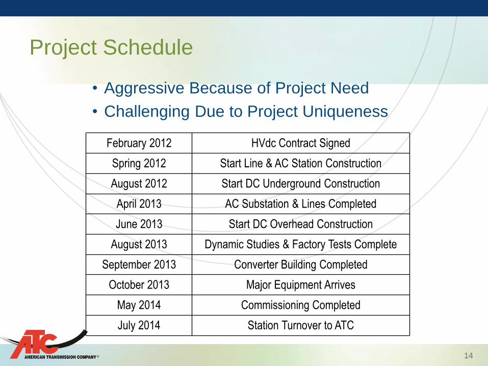
• Aggressive Because of Project Need
• Challenging Due to Project Uniqueness
Project Schedule
February 2012 HVdc Contract Signed
Spring 2012 Start Line & AC Station Construction
August 2012 Start DC Underground Construction
April 2013 AC Substation & Lines Completed
June 2013 Start DC Overhead Construction
August 2013 Dynamic Studies & Factory Tests Complete
September 2013 Converter Building Completed
October 2013 Major Equipment Arrives
May 2014 Commissioning Completed
July 2014 Station Turnover to ATC
15
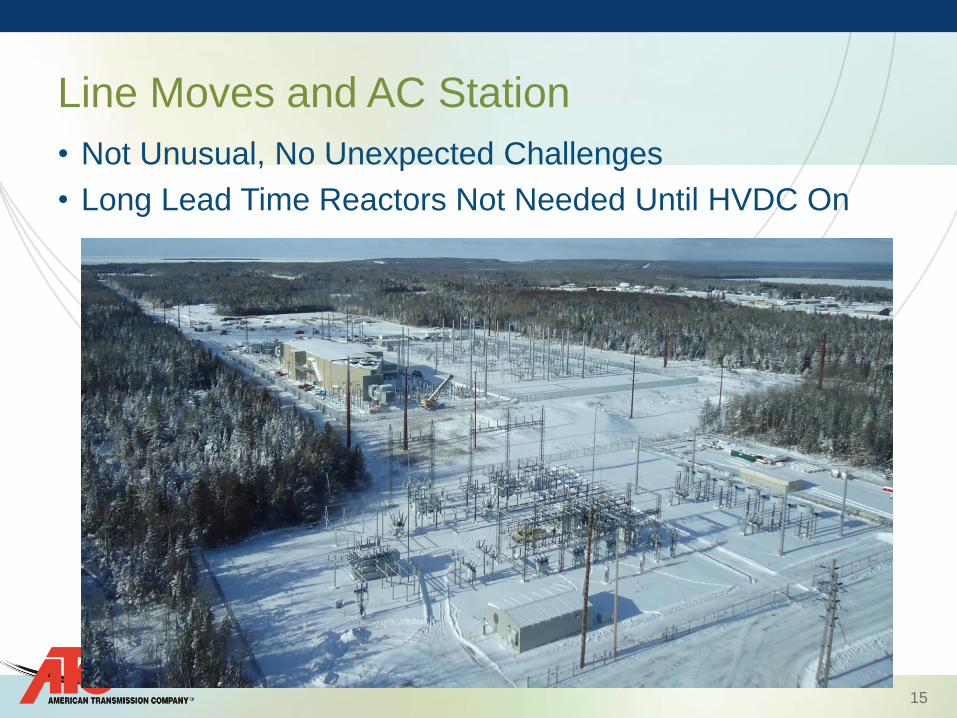
• Not Unusual, No Unexpected Challenges
• Long Lead Time Reactors Not Needed Until HVDC On
Line Moves and AC Station
16
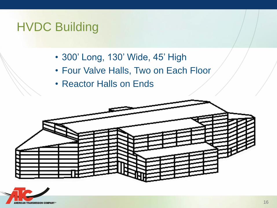
• 300’ Long, 130’ Wide, 45’ High
• Four Valve Halls, Two on Each Floor
• Reactor Halls on Ends
HVDC Building

17
HVDC Building

18
Mackinac AC and HVDC Substations

19
Valve Hall

20
Reactor Hall

21
• Studies and Factory Tests Completion Scheduled Only
One Month Before Major Equipment Arrival – Control Changes Made via Software not Hardware
• Equipment in October Commissioning Completed in May – Much Work Done in Winter Outdoors (Trenches, Wiring, etc.)
– July Completion to Give 60 Days for 30 Day Run
Project Schedule Issues
22
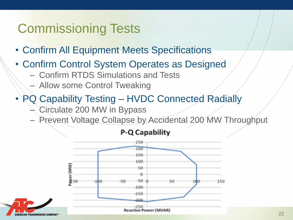
• Confirm All Equipment Meets Specifications
• Confirm Control System Operates as Designed – Confirm RTDS Simulations and Tests
– Allow some Control Tweaking
• PQ Capability Testing – HVDC Connected Radially – Circulate 200 MW in Bypass
– Prevent Voltage Collapse by Accidental 200 MW Throughput
Commissioning Tests
23
Control System Tests
• Tests Included: Power Order, Active Power Control,
Reactive Power Control (both terminals independently &
Simultaneously), AC Voltage Control, High Power
Transfer, Black Start, By-Pass, etc.
• Islanding Test – Match DC Power to that of Small Part of UP
– Isolate that Small Part of UP
– Wait (45 Seconds) for Shift to Island Mode
– Successful Test
• No ACLE Disturbance Test (Manually Triggered ACLE)
24
• High Frequency Resonance in Local Power Line
Carrier Equipment
• May 28th Short Circuit in Valve Hall
• July 16th Power Deviation (Loss of Voltage Signal)
• August 27th HVDC Response to a Remote Fault
• Power System Communications Issues
Issues During (and After) Commissioning Tests
25
• Local PLC Equipment Failed Soon After HVDC Energization
• High Voltage in High Frequency Resonant Circuit
• No Remote Failures, but Excessive Voltages Measured
• Source Wide Band High Frequency (kHz) Signals – Normally Attenuated by Transformer or Distance – Nothing (but PLC) at Transmission Voltages to Resonate
• Doubly Tuned (5th and 30th) Harmonic Filter Ineffective
• Option: Alternate Communication Method (Rejected)
• Solution: Add High Pass Filter – Concerns: Cost and Time to Implement
Local Power Line Carrier Issues

26
• Modify Existing Filter
(Bypass Reactor)
• Convert 30th Harmonic
to High Pass
• Project Harmonic
Distortion Limits Met
• Filter Components Not
Over Stressed
• Implemented Quickly
at Low Cost on Both
Terminals
PLC Issue Solution
R3C2 L2
C1
L1
C1
C2 L2 R3
Original Modified
27
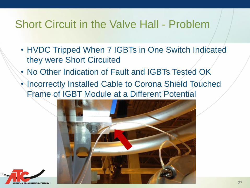
• HVDC Tripped When 7 IGBTs in One Switch Indicated
they were Short Circuited
• No Other Indication of Fault and IGBTs Tested OK
• Incorrectly Installed Cable to Corona Shield Touched
Frame of IGBT Module at a Different Potential
Short Circuit in the Valve Hall - Problem
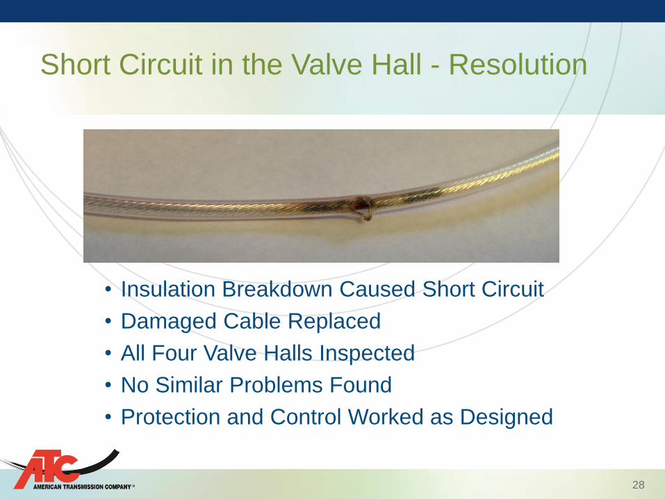
28
• Insulation Breakdown Caused Short Circuit
• Damaged Cable Replaced
• All Four Valve Halls Inspected
• No Similar Problems Found
• Protection and Control Worked as Designed
Short Circuit in the Valve Hall - Resolution
29
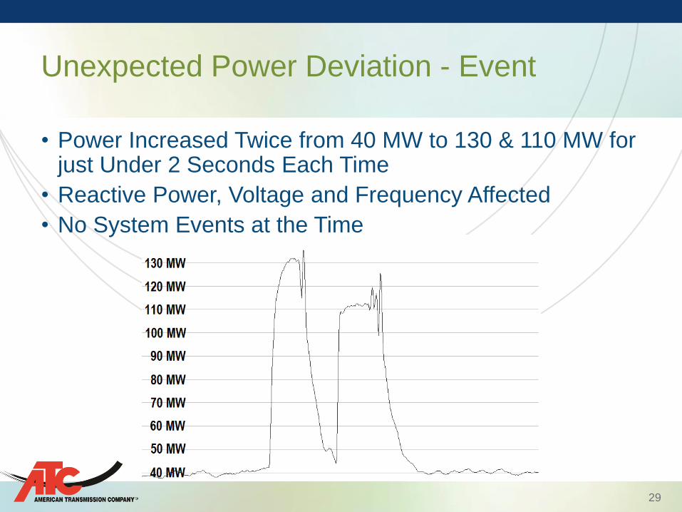
• Power Increased Twice from 40 MW to 130 & 110 MW for just Under 2 Seconds Each Time
• Reactive Power, Voltage and Frequency Affected
• No System Events at the Time
Unexpected Power Deviation - Event
30
• Technician in Control Panel Looking for Measurement Connection
• Touched Loose CCVT Phase and Neutral Wire Connection Changed Ambient Noise (Touched Again to Confirm)
• One Phase Voltage Measurement Lost
• “A” System Voltage Lost, “B” System and Others OK
• System Protection Responded as it Should Have
• 200 milliseconds from Tripping HVDC
• “Do Not Touch” Order Until Connections Re-examined
Unexpected Power Deviation - Resolution

31
• 345 kV Tower on Line Bringing Power from WI to UP
Knocked Down by a Logging Truck on a Clear Day
• HVDC Temporarily Increased Power into the UP
• Increased Mvars Temporarily South, Permanently North
HVDC Response to a Remote Fault

32
• ACLE Not in Service – Waiting Operations Study Completion
– If in Service Power would have Changed Permanently
– Operators Manually Increased Flow from 40 to 65 MW
• PSSE Dynamic and PSCAD Transient Simulations – PSSE a Simplification of PSCAD’s Detailed Control Model
– PSSE Showed Better Response – Due to Delay Lost in
Model Conversion
– To Improve System Response Delay Removed from
PSCAD and Real System
HVDC Response to a Remote Fault

33
• VSC HVDC Uses 3.37th Harmonic Switching Frequency
• IGBT Switching Capabilities to improve Stability by
Continuously Adjusting its Operating Point
• This Creates Non-Repetitive (Interharmonic) Distortion
• Smart Meters Report Energy Usage and Track Outages
• Smart Meters Communicate by Transiently Distorting
System Voltage or Current (or Both)
• Information Extracted by Subtracting Consecutive 60 Hz
• Effective with Error Checking and Multiple Attempts
• Unaffected by Harmonic Distortion – Susceptible to Non-
repetitive Interference (Arc Furnaces, etc.)
Power System Communications Issue
34
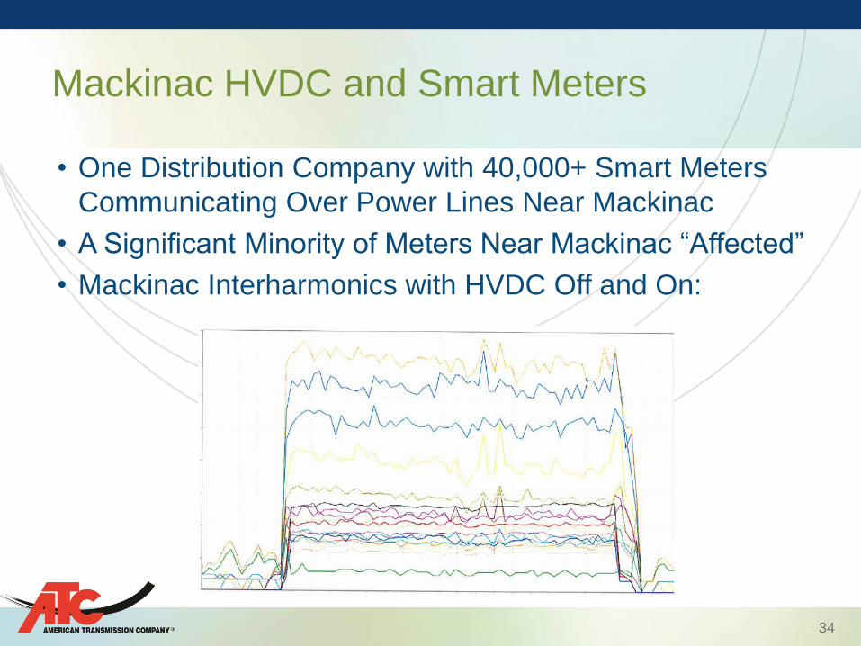
• One Distribution Company with 40,000+ Smart Meters
Communicating Over Power Lines Near Mackinac
• A Significant Minority of Meters Near Mackinac “Affected”
• Mackinac Interharmonics with HVDC Off and On:
Mackinac HVDC and Smart Meters

35
• How Does Each Interharmonic Affect Communications?
Interharmonics Change with HVDC and
System Changes
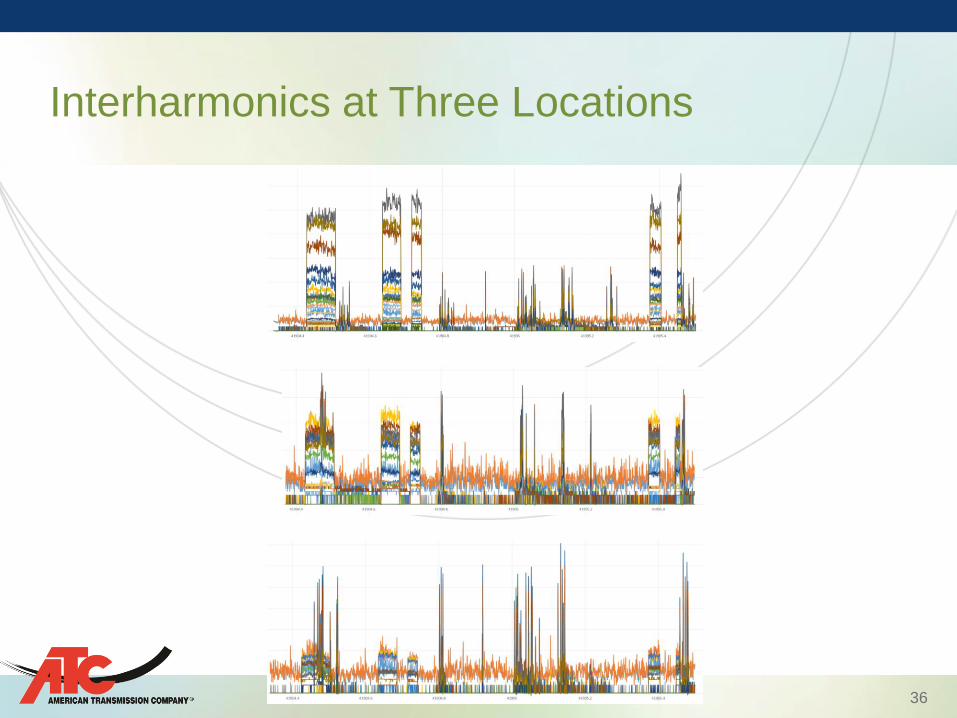
36
Interharmonics at Three Locations

37
• Exist only for Flicker (<120 Hz)
• IEEE 519-2014 “develop on a case-by-case basis”
• IEC 61000-2-2 suggests 0.2 to 0.3% Individual – Seems Designed to Allow Some Communication
• Over a Decade Ago IEEE Working Group on
Interharmonics Looked at Limits Based on Equipment – Similar to Harmonic Voltage Limits (1.5% Individual, 2.5%
THD at 138 kV)
– Almost an Order of Magnitude Higher than IEC
– Never Made it into any IEEE Standard
• Should Power Lines be Used for Communications?
Interharmonic Limits

38
For Now:
• HVDC is in Service for Its Primary Purpose – Facilitating Deferred Maintenance Outages
• HVDC is Taken Out of Service to Facilitate Periodic Meter Reading and When Storms Approach
Future:
• Investigating HVDC-Smart Meter Interaction
• Key HVDC Functionality Produces Some Interharmonics
• Can HVDC be Modified or Operated to Decrease Interharmoncs to and Acceptable Level?
• Expect Some Meter Fixes and New Communication Path for Some Substations
Interharmonic Issue Resolution

39
• Mackinac HVDC Met its Goals Economically and Timely
• Any Project using New Technology in a Unique Part of the
System will have Implementation Issues
Two Key Lessons Learned
• The Need to Study High Frequency Issues – Especially if
Power Line Carrier Installed Locally (High Pass Filter)
• Potential for VSC HVDC Interharmonics to Interfere with
Smart Grid Power Line Communications – The Same Problem Could Exist with Type 4 Wind Turbines
Controls which use IGBTs (arc furnaces, CFLs, etc.)
Conclusions
40
Questions?